WO2018025829A1 - 生体磁気測定装置 - Google Patents
生体磁気測定装置 Download PDFInfo
- Publication number
- WO2018025829A1 WO2018025829A1 PCT/JP2017/027794 JP2017027794W WO2018025829A1 WO 2018025829 A1 WO2018025829 A1 WO 2018025829A1 JP 2017027794 W JP2017027794 W JP 2017027794W WO 2018025829 A1 WO2018025829 A1 WO 2018025829A1
- Authority
- WO
- WIPO (PCT)
- Prior art keywords
- magnetic sensor
- sensor
- biomagnetism
- magnetic
- biomagnetism measuring
- Prior art date
- Legal status (The legal status is an assumption and is not a legal conclusion. Google has not performed a legal analysis and makes no representation as to the accuracy of the status listed.)
- Ceased
Links
Images






Classifications
-
- A—HUMAN NECESSITIES
- A61—MEDICAL OR VETERINARY SCIENCE; HYGIENE
- A61B—DIAGNOSIS; SURGERY; IDENTIFICATION
- A61B5/00—Measuring for diagnostic purposes; Identification of persons
- A61B5/24—Detecting, measuring or recording bioelectric or biomagnetic signals of the body or parts thereof
- A61B5/242—Detecting biomagnetic fields, e.g. magnetic fields produced by bioelectric currents
-
- A—HUMAN NECESSITIES
- A61—MEDICAL OR VETERINARY SCIENCE; HYGIENE
- A61B—DIAGNOSIS; SURGERY; IDENTIFICATION
- A61B5/00—Measuring for diagnostic purposes; Identification of persons
- A61B5/05—Detecting, measuring or recording for diagnosis by means of electric currents or magnetic fields; Measuring using microwaves or radio waves
-
- A—HUMAN NECESSITIES
- A61—MEDICAL OR VETERINARY SCIENCE; HYGIENE
- A61B—DIAGNOSIS; SURGERY; IDENTIFICATION
- A61B5/00—Measuring for diagnostic purposes; Identification of persons
- A61B5/24—Detecting, measuring or recording bioelectric or biomagnetic signals of the body or parts thereof
- A61B5/25—Bioelectric electrodes therefor
- A61B5/251—Means for maintaining electrode contact with the body
-
- A—HUMAN NECESSITIES
- A61—MEDICAL OR VETERINARY SCIENCE; HYGIENE
- A61B—DIAGNOSIS; SURGERY; IDENTIFICATION
- A61B5/00—Measuring for diagnostic purposes; Identification of persons
- A61B5/68—Arrangements of detecting, measuring or recording means, e.g. sensors, in relation to patient
- A61B5/6801—Arrangements of detecting, measuring or recording means, e.g. sensors, in relation to patient specially adapted to be attached to or worn on the body surface
- A61B5/6843—Monitoring or controlling sensor contact pressure
-
- G—PHYSICS
- G01—MEASURING; TESTING
- G01R—MEASURING ELECTRIC VARIABLES; MEASURING MAGNETIC VARIABLES
- G01R33/00—Arrangements or instruments for measuring magnetic variables
- G01R33/02—Measuring direction or magnitude of magnetic fields or magnetic flux
-
- G—PHYSICS
- G01—MEASURING; TESTING
- G01R—MEASURING ELECTRIC VARIABLES; MEASURING MAGNETIC VARIABLES
- G01R33/00—Arrangements or instruments for measuring magnetic variables
- G01R33/02—Measuring direction or magnitude of magnetic fields or magnetic flux
- G01R33/04—Measuring direction or magnitude of magnetic fields or magnetic flux using the flux-gate principle
-
- G—PHYSICS
- G01—MEASURING; TESTING
- G01R—MEASURING ELECTRIC VARIABLES; MEASURING MAGNETIC VARIABLES
- G01R33/00—Arrangements or instruments for measuring magnetic variables
- G01R33/02—Measuring direction or magnitude of magnetic fields or magnetic flux
- G01R33/06—Measuring direction or magnitude of magnetic fields or magnetic flux using galvano-magnetic devices
- G01R33/09—Magnetoresistive devices
-
- A—HUMAN NECESSITIES
- A61—MEDICAL OR VETERINARY SCIENCE; HYGIENE
- A61B—DIAGNOSIS; SURGERY; IDENTIFICATION
- A61B5/00—Measuring for diagnostic purposes; Identification of persons
- A61B5/02—Detecting, measuring or recording for evaluating the cardiovascular system, e.g. pulse, heart rate, blood pressure or blood flow
- A61B5/0205—Simultaneously evaluating both cardiovascular conditions and different types of body conditions, e.g. heart and respiratory condition
-
- A—HUMAN NECESSITIES
- A61—MEDICAL OR VETERINARY SCIENCE; HYGIENE
- A61B—DIAGNOSIS; SURGERY; IDENTIFICATION
- A61B5/00—Measuring for diagnostic purposes; Identification of persons
- A61B5/08—Measuring devices for evaluating the respiratory organs
- A61B5/0816—Measuring devices for examining respiratory frequency
-
- G—PHYSICS
- G01—MEASURING; TESTING
- G01R—MEASURING ELECTRIC VARIABLES; MEASURING MAGNETIC VARIABLES
- G01R33/00—Arrangements or instruments for measuring magnetic variables
- G01R33/02—Measuring direction or magnitude of magnetic fields or magnetic flux
- G01R33/06—Measuring direction or magnitude of magnetic fields or magnetic flux using galvano-magnetic devices
- G01R33/063—Magneto-impedance sensors; Nanocristallin sensors
Definitions
- the present invention relates to a biomagnetism measuring apparatus using a magnetic sensor.
- MR sensors are widely used as magnetic heads of hard disk devices, rotation sensors (encoders), and position sensors.
- mobile devices such as smartphones and tablet devices have become widespread, and mobile devices have built-in azimuth sensors using MR sensors that measure azimuth using geomagnetism.
- Information obtained from the azimuth sensor is used for navigation or the like using position information by GPS (Global Positioning System).
- biomagnetism measuring devices such as a magnetoencephalograph, a magnetocardiograph, and a magnetomagnetometer that detect weak low-frequency magnetism generated in association with the electrical activity of the brain, heart, and muscle of the living body are used in the medical field.
- the magnetoencephalogram generated by the electrical activity of the brain is about one hundred millionth the intensity of the geomagnetism
- the magnetocardiogram generated by the electrical activity of the heart's myocardium is one millionth of the geomagnetism.
- the size is about one. Therefore, when detecting magnetism generated by a living body (hereinafter also referred to as “biomagnetism”), the magnetic sensor is required to have extremely high detection performance.
- a superconducting quantum interference element (Superducting Quantum Interference Device, hereinafter also referred to as “SQUID”) is known (for example, see Patent Document 1).
- a plurality of SQUID sensors are arranged in an array in the dewar.
- the SQUID sensor when the SQUID sensor is disposed, the SQUID sensor must be disposed so as not to electromagnetically affect the Josephson junction inside the SQUID. For this reason, it is not easy to change, replace, and take out the SQUID sensor.
- the SQUID sensor is an ultra-sensitive magnetic sensor, there are problems such as being unable to be sufficiently close to the living body and being difficult to handle.
- Patent Document 2 proposes a biomagnetism measuring apparatus in which a covering member that shields a living body from an external magnetic field is formed in a helmet shape or a cylindrical shape, and an MR sensor is lined in an array shape on the covering member.
- a covering member that shields a living body from an external magnetic field is formed in a helmet shape or a cylindrical shape, and an MR sensor is lined in an array shape on the covering member.
- the optimal position of the MR sensor differs for measurement objects having different body shapes, such as adults, children, and animals other than humans.
- the optimum position of the MR sensor varies depending on the region to be measured, such as the head, heart, and limbs.
- the inventors of the present invention have intensively studied to solve the above problems.
- a biomagnetism measuring apparatus that can detect biomagnetism with high accuracy regardless of the measurement target by movably holding a plurality of magnetic sensors and moving the magnetic sensor to an optimal position according to the measurement target.
- the present invention has been found, and the present invention has been completed. Specifically, the present invention provides the following.
- the present invention provides a plurality of magnetic sensors for detecting biomagnetism, a holding portion having a holding hole for individually moving the plurality of magnetic sensors, and the magnetic sensor contacting and separating from the measurement object. And a moving mechanism for individually moving in the approaching / separating direction.
- the present invention is the biomagnetic measurement apparatus according to (1), wherein the moving mechanism is at least one of a pneumatic mechanism, a hydraulic mechanism, an elastic body mechanism, a screw mechanism, or a gear mechanism.
- the present invention is the biomagnetic measurement apparatus according to (1) or (2), wherein the moving mechanism is made of a nonmagnetic material.
- the present invention is the biomagnetic measurement apparatus according to any one of (1) to (5), wherein the magnetic sensor further includes a biological information acquisition unit that acquires biological information.
- the present invention is the biomagnetism measuring device according to any one of (1) to (6), wherein the magnetic sensor is arranged immediately below the measurement target.
- the present invention is the biomagnetism measuring device according to any one of (1) to (7), wherein the holding portion is made of a flexible material.
- biomagnetism measuring apparatus capable of detecting biomagnetism with high accuracy regardless of the measurement object.
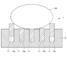
- FIG. 1 is a plan view showing an example of a biomagnetic measurement apparatus according to an embodiment of the present invention.
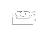
- FIG. 2 is a schematic diagram for explaining the positional relationship between the subject and each magnetic sensor of the biomagnetism measuring apparatus, and shows a cross section taken along the line AA ′ in the biomagnetism measuring apparatus shown in FIG.
- the biomagnetism measuring apparatus 1 includes a plurality of magnetic sensors 11 that detect biomagnetism, a holding portion 12 that has a holding hole 12 a that holds the magnetic sensor 11 movably, and a magnetic sensor. And a moving mechanism that moves the 11 detection surfaces in a direction in contact with and away from the living body 100 (hereinafter also referred to as “subject”).
- the magnetic sensor 11 detects biomagnetism generated from the living body 100 as a measurement target.
- Examples of the magnetic sensor 11 include a giant magnetoresistive sensor (GMR sensor), a tunnel magnetoresistive sensor (TMR sensor), an anisotropic magnetoresistive sensor (AMR sensor), a magnetic impedance sensor (MI sensor), and a fluxgate sensor.
- the magnetic sensor 11 used in this embodiment may be any magnetic sensor as long as it can detect a magnetic field (normal component) of about 10 ⁇ 4 T (tesla) to 10 ⁇ 10 T (tesla). .
- the magnetic sensor 11 used in the present embodiment can obtain the same level of information as the SQUID sensor, can be used at room temperature, does not need to be placed in a dewar for storing cooling, and uses a SQUID sensor Compared with the living body 100, the handling is simple and it is easy to approach the living body 100.
- the magnetic sensor 11 may or may not have wiring for signal exchange and power supply. However, as shown in FIG. 1, in the biomagnetism measuring apparatus 1, since the several magnetic sensor 11 is arrange
- the signal detected by the magnetic sensor 11 is sent to the control unit.
- biomagnetic information is generated from the signals detected by the magnetic sensors 11, converted into image information, and output to the display device.
- holding holes 12a for holding the plurality of magnetic sensors 11 individually and movably are arranged in an array.
- FIG. 1 illustrates an example in which the holding holes 12a are arranged in a 5 ⁇ 5 array, but the arrangement direction and the number of the holding holes 12a (magnetic sensors 11) depend on the measurement target and the measurement site. May be selected as appropriate.
- the holding unit 12 described above is preferably composed of a plastic material such as an acrylic resin, a non-ferrous metal such as aluminum, titanium, copper, brass, a specially processed stainless steel alloy, or a non-magnetic material such as wood. Even if the holding unit 12 vibrates due to movement of the subject 100 such as breathing, the holding unit 12 is made of a non-magnetic material, so that fluctuations in environmental magnetism can be suppressed. Therefore, it is possible to suppress the influence of environmental magnetism fluctuations on the magnetic sensor 11.
- a plastic material such as an acrylic resin
- a non-ferrous metal such as aluminum, titanium, copper, brass, a specially processed stainless steel alloy
- a non-magnetic material such as wood.
- the moving mechanism individually moves the magnetic sensor 11 in the approaching / separating direction to contact / separate the living body 100 to bring the detection surface of the magnetic sensor 11 into close contact with the living body 100 that is the measurement target.
- the moving mechanism is not particularly limited as long as the magnetic sensor 11 can be moved to a predetermined position, and examples thereof include a pneumatic mechanism, a hydraulic mechanism, an elastic body mechanism, a screw mechanism, and a gear mechanism.
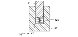
- FIG. 6 is an enlarged schematic view of a main part showing an example of a biomagnetism measuring apparatus provided with an elastic body mechanism.
- the same members as those shown in FIGS. 1 and 2 are denoted by the same reference numerals, and description thereof is omitted.
- the elastic body mechanism 30 has an elastic body 31 such as a coiled spring in the holding hole 12a, and increases or decreases the amount of expansion / contraction of the elastic body 31 by a reaction force from the measurement target.
- the detection surface of the magnetic sensor 11 in 12a is closely attached to the measurement object.
- the elastic body mechanism 30 is preferable in that it does not require a drive source and has a simple configuration.
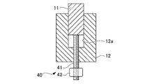
- FIG. 7 is an enlarged schematic view of a main part showing an example of a biomagnetism measuring apparatus provided with a screw mechanism.
- the screw mechanism 40 includes a screw shaft 41 and a screw nut 42 into which the screw shaft 41 is screwed.
- a drive motor not shown
- the amount of rotation of the screw shaft 41 is increased.
- the detection surface of the magnetic sensor 11 in the holding hole 12a is moved in a direction in contact with the measurement object or a direction away from the measurement object.
- the screw mechanism 40 is preferable in that the control unit can increase or decrease the amount of rotation of the screw shaft 41 to individually move the magnetic sensor 11 to a desired position.
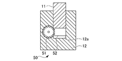
- FIG. 8 is an enlarged schematic view of a main part showing an example of a biomagnetism measuring apparatus provided with a gear mechanism.
- the gear mechanism 50 includes a gear 51 and a meshing portion 52 that meshes with the gear 51.
- the gear 51 is rotated by a drive motor (not shown) to increase or decrease the amount of movement of the meshing portion 52.
- the magnetic sensor 11 in the holding hole 12a is moved.
- the gear 51 may be composed of a plurality of gears.
- the gear mechanism 50 is preferable in that the control unit can increase or decrease the amount of movement of the meshing unit 52 to individually move the magnetic sensor 11 to a desired position.
- the members constituting the moving mechanism such as the elastic body mechanism 30, the screw mechanism 40, and the gear mechanism 50 described above are plastic materials such as acrylic resin, aluminum, titanium, copper, brass, non-ferrous metals such as specially processed stainless steel alloys, It is preferably composed of a nonmagnetic material such as wood. Even if each member moves due to the operation of the moving mechanism, the variation in environmental magnetism can be suppressed by configuring each member with a non-magnetic material. Therefore, it is possible to suppress the influence of environmental magnetism fluctuations on the magnetic sensor 11.
- the biomagnetism measuring apparatus 1 may control the movement amount of each magnetic sensor 11 by the movement mechanism by the control unit.
- the control unit controls the moving mechanisms such as the pneumatic / hydraulic mechanism 20, the screw mechanism 40, and the gear mechanism 50 described above based on external biological information and the like, and adjusts the moving amount of each magnetic sensor 11. Good.
- FIG. 9 is a block diagram showing a configuration of a biomagnetism measuring apparatus including a control unit that determines the amount of movement based on external biometric information.
- the control unit 13 of the biomagnetism measuring apparatus 1 stores the biometric information 101 acquired in advance in the memory 14, and the biometric information 101 stored by the central processing unit (CPU) 15.
- the number of rotations of the plurality of drive motors 16 provided in the movement mechanism may be calculated to control the movement amount of each magnetic sensor 11.
- the biomagnetism measuring apparatus 1 can move each magnetic sensor 11 to an appropriate position according to the biometric information 101.
- the biological information 101 from the outside include biological section information such as the physique of the subject 100 obtained by MRI measurement.
- the magnetic sensor 11 further acquires detection means for detecting information other than the magnetic information of the living body 100, for example, contact detecting means for detecting the presence / absence of contact between the magnetic sensor 11 and the living body 100, and information on the living body 100. It is also possible to provide biological information acquisition means.
- the magnetic sensor 11 may include a pressure sensor and a position sensor as contact detection means for detecting the presence or absence of contact with the living body 100.
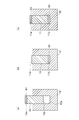
- FIGS. 10A, 10B, and 10C are enlarged schematic views of main parts showing an example of a configuration in which the magnetic sensor includes a pressure sensor that detects the presence or absence of contact with a living body.
- the magnetic sensor 11 may include a pressure sensor 61 that detects the presence or absence of contact with the living body 100 on the detection surface 11a facing the measurement target.
- the magnetic sensor 11 may be provided with the pressure sensor 61 in the surface 11b which opposes the detection surface 11a of the magnetic sensor 11, as shown in FIG.10 (b).
- the magnetic sensor 11 may be provided with the pressure sensor 61 in both the detection surface 11a of the magnetic sensor 11, and the surface 11b facing the detection surface 11a.
- the pressure sensor 61 installed on the surface 11b facing the detection surface 11a of the magnetic sensor 11 detects a stress that is a combination of the stress from the measurement target and the stress from the moving mechanism, and the control unit 13 detects this pressure. Based on the detection result of the sensor 61, the presence or absence of contact between the magnetic sensor 11 and the living body 100 is determined.
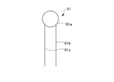
- the pressure sensor 61 may be any sensor that outputs a pressure signal corresponding to the applied pressure to the control unit 13. For example, as shown in FIG. 11, the pressure sensor 61 measures a pressure from a measurement target with a pressure-sensitive element via a diaphragm 61a, converts the pressure into an electrical signal, and connects the two connection cables 61b and 61c. To the control unit 13.
- the control unit 13 can determine whether or not the magnetic sensor 11 and the living body 100 are in contact with each other based on the electrical signal output from the pressure sensor 61 or the position sensor.
- the control unit 13 may not transmit / receive signals or supply power to / from the magnetic sensor 11 that is not in contact with the measurement target, and power saving can be achieved.
- the control part 13 can select only the information from the magnetic sensor 11 which is contacting the measuring object, and can produce
- the magnetic sensor 11 may include a biological electrode or a pressure sensor as biological information acquisition means for acquiring biomagnetic information.
- FIG. 12 is a schematic diagram illustrating an example of a configuration in which the magnetic sensor includes detection means for detecting biological information.
- the magnetic sensor 11 may have a biological electrode 62 that is a biological information acquisition unit on a detection surface facing the measurement target.
- the biological electrode 62 includes an electrode unit 62a, and sends the biological information acquired by the electrode unit 62a to the control unit 13 via the connection cable 62b.
- the biological information acquired by the biological electrode 62 or the pressure sensor include an electrocardiogram, a heartbeat, a pulse, the number of breaths, and myoelectric potential.
- the control unit 13 can additionally acquire biological information other than the biomagnetic information, and can convert the biological information into image information and output it to the display device. Therefore, the measurer can obtain a plurality of pieces of information with one biomagnetism measuring device and one measurement.
- the magnetic sensor 11 of the holding unit 12 ′ may include a position sensor 63 that detects the position of the magnetic sensor 11 and an angle sensor 64 that detects the tilt of the magnetic sensor 11.
- the control unit 13 may calculate the relative position between the magnetic sensor 11 and the measurement target based on the detection results of the position sensor 63 and the angle sensor 64, and may perform biomagnetism magnetic distribution, current source estimation, and the like.
- the control unit 13 may convert these into image information and display it on a display device.
Landscapes
- Health & Medical Sciences (AREA)
- Life Sciences & Earth Sciences (AREA)
- Physics & Mathematics (AREA)
- Animal Behavior & Ethology (AREA)
- Medical Informatics (AREA)
- Veterinary Medicine (AREA)
- Public Health (AREA)
- Biophysics (AREA)
- Pathology (AREA)
- Engineering & Computer Science (AREA)
- Biomedical Technology (AREA)
- Heart & Thoracic Surgery (AREA)
- General Health & Medical Sciences (AREA)
- Molecular Biology (AREA)
- Surgery (AREA)
- Condensed Matter Physics & Semiconductors (AREA)
- General Physics & Mathematics (AREA)
- Nuclear Medicine, Radiotherapy & Molecular Imaging (AREA)
- Radiology & Medical Imaging (AREA)
- Measurement And Recording Of Electrical Phenomena And Electrical Characteristics Of The Living Body (AREA)
- Measuring Magnetic Variables (AREA)
Abstract
本発明は、測定対象によらず、生体磁気を精度よく検出可能な生体磁気測定装置を提供することを目的とする。 本発明の生体磁気測定装置(1)は、生体(100)の生体磁気を検出する複数の磁気センサ(11)と、複数の磁気センサ(11)を個別に可動自在に保持する保持孔(12a)を有する保持部(12)と、磁気センサ(11)を生体(100)に対して接離する接離方向へ個別に移動させる移動機構とを備える。移動機構としては、例えば、空気圧・油圧機構(20)、弾性体機構(30)、ネジ機構(40)、歯車機構(50)等が挙げられる。
Description
本発明は、磁気センサを用いた生体磁気測定装置に関する。
磁気を検出する磁気センサに関し、従来より、磁気抵抗効果素子(MR素子)を用いたMRセンサが知られている。磁界の強さに応じて、MR素子にかかる直流抵抗が変化する。この直流抵抗の変化の程度を利用して、MRセンサは、磁界の変化や磁性体の有無を電圧の変化として検出する。
MRセンサは、ハードディスク装置の磁気ヘッドや、回転センサ(エンコーダ)、位置センサとして広く利用されている。また、近年、スマートフォンやタブレット機器等のモバイル機器が普及しており、モバイル機器には地磁気を利用して方位を計測するMRセンサを用いた方位センサが内蔵されている。方位センサから得られる情報は、GPS(Global Positionning System)による位置情報を利用したナビゲーション等に用いられる。
しかしながら、これら工業応用分野では、高感度な磁気検出技術を必要としていない。例えば、回転センサや位置センサにおいては、磁石等を基準信号とするので、高感度の磁気検出を必須としていない。また、方位センサは、地磁気を基準として絶対方位を検出すれば足り、高感度の磁気検出を必須としていない。
ところで、近年、医療現場において、生体の脳、心臓、筋肉の電気活動に伴って発生する微弱な低周波の磁気を検出する脳磁計、心磁計、筋磁計といった生体磁気測定装置が使用されている。脳の電気的活動に伴って発生する脳磁は、地磁気の約1億分の1程度の強度であり、心臓の心筋の電気的活動に伴って発生する心磁は、地磁気の百万分の1程度の大きさである。そのため、生体が発生する磁気(以下、「生体磁気」ともいう。)を検出するに際し、磁気センサには、極めて高感度な検出性能が要求される。
高感度な磁気検出を可能にする高感度磁気センサとして、超電導量子干渉素子(Superconducting Quantum Interference Device、以下、「SQUID」ともいう。)が知られている(例えば、特許文献1参照。)。
SQUIDセンサは、超電導現象を利用した磁気センサであり、ジョセフソン接合を有する。そのため、SQUIDセンサを用いるに際し、液体ヘリウムや液体窒素といった冷媒による冷却を要する。したがって、SQUIDセンサは、冷媒を貯蔵するデュワー内に設けられなければならず、生体磁気を検出するにあたり、SQUIDセンサを生体と密着させることが難しい。
また、SQUIDセンサは、デュワー内にアレイ状に複数配置されている。しかしながら、SQUIDセンサを配置するにあたって、SQUIDセンサは、SQUID内部のジョセフソン接合に電磁気的な影響が及ばないように配置しなければならない。そのため、SQUIDセンサの配置変更、取替え、取り出し等は、容易ではない。
このように、SQUIDセンサは、超高感度な磁気センサであるにもかかわらず、生体に対して十分に近づけることができず、取り扱いが難しい等の課題がある。
そこで、冷却が不要な常温域で、微弱な磁気の検出が可能なMRセンサを用いた生体磁気測定装置が提案されている。例えば、特許文献2には、生体を外部磁場からシールドする被覆部材をヘルメット状又は円筒状に形成し、この被覆部材にMRセンサをアレイ状に内張りした生体磁気測定装置が提案されている。MRセンサを用いた生体磁気測定装置では、MRセンサをデュワー内に配置する必要がなく、SQUIDセンサを用いる場合に比べ、取り扱いが簡単で、MRセンサを生体に近づけやすい。
しかしながら、特許文献2に記載の生体磁気測定装置のように、MRセンサの位置が固定されていると、測定対象(生体)によっては、測定対象とMRセンサとの密着性がなくなり、MRセンサが磁気を検出できない場合がある。例えば、大人や子供、ヒト以外の動物等のように体型が異なる測定対象では、最適なMRセンサの位置が異なる。また、頭部、心臓、四肢等、測定対象の部位によっても、最適なMRセンサの位置が異なる。
本発明は、測定対象によらず、生体磁気を精度よく検出可能な生体磁気測定装置を提供することを目的とする。
本発明者らは、上記のような課題を解決するために鋭意研究を重ねた。その結果、複数の磁気センサを可動自在に保持させ、測定対象に応じて磁気センサを最適な位置に移動させることにより、測定対象によらず、生体磁気を精度よく検出可能な生体磁気測定装置を提供できることを見出し、本発明を完成するに至った。具体的に、本発明は、以下のものを提供する。
(1)本発明は、生体磁気を検出する複数の磁気センサと、前記複数の磁気センサを個別に可動自在に保持する保持孔を有する保持部と、前記磁気センサを測定対象に対して接離する接離方向へ個別に移動させる移動機構と、を備える生体磁気測定装置である。
(2)本発明は、前記移動機構は、空気圧機構、油圧機構、弾性体機構、ネジ機構又は歯車機構の少なくとも一つである、(1)に記載の生体磁気測定装置である。
(3)本発明は、前記移動機構は、非磁性材料から構成される、(1)又は(2)に記載の生体磁気測定装置である。
(4)本発明は、前記移動機構による前記磁気センサの移動量を、外部からの生体情報に基づき制御する制御手段を備える、(1)から(3)のいずれかに記載の生体磁気測定装置である。
(5)本発明は、前記磁気センサは、測定対象との接触の有無を検出する接触検出手段をさらに備える、(1)から(4)のいずれかに記載の生体磁気測定装置である。
(6)本発明は、前記磁気センサは、生体情報を取得する生体情報取得手段をさらに備える、(1)から(5)のいずれかに記載の生体磁気測定装置である。
(7)本発明は、前記磁気センサは、測定対象の直下に配される、(1)から(6)のいずれかに記載の生体磁気測定装置である。
(8)本発明は、前記保持部は、可撓性材料から構成される、(1)から(7)のいずれかに記載の生体磁気測定装置である。
本発明によれば、測定対象によらず、生体磁気を精度よく検出可能な生体磁気測定装置を提供することができる。
以下、本発明の実施形態について詳細に説明するが、本発明は、以下の実施形態に何ら限定されるものではなく、本発明の目的の範囲内において、適宜変更を加えて実施することができる。
<生体磁気測定装置1>
図1は、本発明の実施形態に係る生体磁気測定装置の一例を示す平面図である。図2は、被験者と生体磁気測定装置の各磁気センサとの位置関係を説明する模式図であって、図1に示す生体磁気測定装置におけるA-A’断面を示す。図1及び図2に示すように、生体磁気測定装置1は、生体磁気を検出する複数の磁気センサ11と、磁気センサ11を可動自在に保持する保持孔12aを有する保持部12と、磁気センサ11の検出面を測定対象である生体(以下、「被験者」ともいう)100に対して接離する方向へ移動させる移動機構とを備えている。
図1は、本発明の実施形態に係る生体磁気測定装置の一例を示す平面図である。図2は、被験者と生体磁気測定装置の各磁気センサとの位置関係を説明する模式図であって、図1に示す生体磁気測定装置におけるA-A’断面を示す。図1及び図2に示すように、生体磁気測定装置1は、生体磁気を検出する複数の磁気センサ11と、磁気センサ11を可動自在に保持する保持孔12aを有する保持部12と、磁気センサ11の検出面を測定対象である生体(以下、「被験者」ともいう)100に対して接離する方向へ移動させる移動機構とを備えている。
[磁気センサ11]
磁気センサ11は、測定対象である生体100から生じる生体磁気を検出する。磁気センサ11としては、巨大磁気抵抗センサ(GMRセンサ)、トンネル磁気抵抗センサ(TMRセンサ)、異方的磁気抵抗センサ(AMRセンサ)、磁気インピーダンスセンサ(MIセンサ)、フラックスゲートセンサ等が挙げられる。本実施形態で使用する磁気センサ11は、10-4T(テスラ)~10-10T(テスラ)程度の磁界(法線成分)を検出することができれば、いずれの磁気センサであってもよい。本実施形態で使用する磁気センサ11は、SQUIDセンサと同程度の情報を得ることができ、かつ、常温で使用可能で、冷却を貯蔵するデュワー内に配置する必要がなく、SQUIDセンサを用いる場合に比べ、取り扱いが簡単で、生体100に近づけやすい。
磁気センサ11は、測定対象である生体100から生じる生体磁気を検出する。磁気センサ11としては、巨大磁気抵抗センサ(GMRセンサ)、トンネル磁気抵抗センサ(TMRセンサ)、異方的磁気抵抗センサ(AMRセンサ)、磁気インピーダンスセンサ(MIセンサ)、フラックスゲートセンサ等が挙げられる。本実施形態で使用する磁気センサ11は、10-4T(テスラ)~10-10T(テスラ)程度の磁界(法線成分)を検出することができれば、いずれの磁気センサであってもよい。本実施形態で使用する磁気センサ11は、SQUIDセンサと同程度の情報を得ることができ、かつ、常温で使用可能で、冷却を貯蔵するデュワー内に配置する必要がなく、SQUIDセンサを用いる場合に比べ、取り扱いが簡単で、生体100に近づけやすい。
磁気センサ11は、信号の授受や電力供給のための配線を有していてもよいし、有していなくてもよい。ただし、図1に示すように、生体磁気測定装置1においては、複数の磁気センサ11が配置されることから、混線を避けるためには、配線を有していることが好ましい。
上記磁気センサ11で検出された信号は、制御部に送られる。制御部では、各磁気センサ11で検出された信号から生体磁気情報を生成し、画像情報化して表示装置に出力する。
[保持部12]
保持部12には、複数の磁気センサ11を個別に可動自在に保持する保持孔12aがアレイ状に配置される。なお、図1では、保持孔12aが5×5のアレイ状に配置されている例を図示しているが、保持孔12a(磁気センサ11)の配列方向やその個数は、測定対象や測定部位によって適宜選択されればよい。
保持部12には、複数の磁気センサ11を個別に可動自在に保持する保持孔12aがアレイ状に配置される。なお、図1では、保持孔12aが5×5のアレイ状に配置されている例を図示しているが、保持孔12a(磁気センサ11)の配列方向やその個数は、測定対象や測定部位によって適宜選択されればよい。
上述した保持部12は、アクリル樹脂等のプラスチック材料、アルミ、チタン、銅、真鍮、特殊加工したステンレス合金等の非鉄金属、木材等の非磁性材料で構成されることが好ましい。被験者100の呼吸等の動きによって、保持部12が振動しても、保持部12が非磁性材料であることにより、環境磁気の変動を抑制することができる。よって、環境磁気の変動による影響が磁気センサ11に及ぶことを抑制することができる。
また、上記保持部12は、磁気センサ11の検出面と測定対象との密着性を高める上で、測定対象の直下に配されることが好ましい。例えば、図3に示すように、被験者100は、保持部12が組み込まれた診療台2上に仰向けに横たわってもよい。または、図4に示すように、被験者100は診療台2上にうつ伏せで横たわってもよい。保持部12が組み込まれた診療台2に被験者100が横たわることにより、被験者100に重力が作用し、被験者100の体表面と磁気センサ11の検出面との密着性を向上させやすい。その結果、生体磁気測定装置1は、より精度の高い生体磁気情報を得ることが可能となる。
[移動機構]
移動機構は、磁気センサ11を生体100に対して接離する接離方向へ個別に移動させ、磁気センサ11の検出面と測定対象である生体100とを密着させる。移動機構としては、磁気センサ11を所定の位置に移動させることができれば、特に制限はないが、例えば、空気圧機構、油圧機構、弾性体機構、ネジ機構、歯車機構等が挙げられる。
移動機構は、磁気センサ11を生体100に対して接離する接離方向へ個別に移動させ、磁気センサ11の検出面と測定対象である生体100とを密着させる。移動機構としては、磁気センサ11を所定の位置に移動させることができれば、特に制限はないが、例えば、空気圧機構、油圧機構、弾性体機構、ネジ機構、歯車機構等が挙げられる。
(空気圧・油圧機構20)
図5は、空気圧・油圧機構を備えた生体磁気測定装置の一例を示す模式図である。なお、図5中、図1及び図2で示した部材と同一部材には、同一符号を付し、説明を省略する。図5に示すように、空気圧・油圧機構20は、保持孔12b内の空気圧又は油圧をポンプ21により増減させることにより、保持孔12b内の磁気センサ11の検出面を、測定対象に接触させる方向、又は離間する方向に移動させる。空気圧・油圧機構20は、磁気センサ11の感度に影響を与えない空気や油を用いる点で好ましい。
図5は、空気圧・油圧機構を備えた生体磁気測定装置の一例を示す模式図である。なお、図5中、図1及び図2で示した部材と同一部材には、同一符号を付し、説明を省略する。図5に示すように、空気圧・油圧機構20は、保持孔12b内の空気圧又は油圧をポンプ21により増減させることにより、保持孔12b内の磁気センサ11の検出面を、測定対象に接触させる方向、又は離間する方向に移動させる。空気圧・油圧機構20は、磁気センサ11の感度に影響を与えない空気や油を用いる点で好ましい。
(弾性体機構30)
図6は、弾性体機構を備えた生体磁気測定装置の一例を示す要部拡大模式図である。なお、図6中、図1及び図2で示した部材と同一部材には、同一符号を付し、説明を省略する。図6に示すように、弾性体機構30は、保持孔12a内にコイル状ばね等の弾性体31を有し、測定対象からの反力により弾性体31の伸縮量を増減させて、保持孔12a内の磁気センサ11の検出面と測定対象とを密着させる。弾性体機構30は、駆動源を必要とせず、簡易な構成である点で好ましい。
図6は、弾性体機構を備えた生体磁気測定装置の一例を示す要部拡大模式図である。なお、図6中、図1及び図2で示した部材と同一部材には、同一符号を付し、説明を省略する。図6に示すように、弾性体機構30は、保持孔12a内にコイル状ばね等の弾性体31を有し、測定対象からの反力により弾性体31の伸縮量を増減させて、保持孔12a内の磁気センサ11の検出面と測定対象とを密着させる。弾性体機構30は、駆動源を必要とせず、簡易な構成である点で好ましい。
(ネジ機構40)
図7は、ネジ機構を備えた生体磁気測定装置の一例を示す要部拡大模式図である。なお、図7中、図1及び図2で示した部材と同一部材には、同一符号を付し、説明を省略する。図7に示すように、ネジ機構40は、ネジ軸41と、ネジ軸41が螺合するネジナット42とを備え、図示しない駆動モーターによりネジナット42を回転駆動させることにより、ネジ軸41の回転量を増減させて、保持孔12a内の磁気センサ11の検出面を、測定対象に接触する方向、又は離間する方向に移動させる。ネジ機構40は、後述するように、制御部によって、ネジ軸41の回転量を増減させ、磁気センサ11を所望の位置に個別に移動させることができる点で好ましい。
図7は、ネジ機構を備えた生体磁気測定装置の一例を示す要部拡大模式図である。なお、図7中、図1及び図2で示した部材と同一部材には、同一符号を付し、説明を省略する。図7に示すように、ネジ機構40は、ネジ軸41と、ネジ軸41が螺合するネジナット42とを備え、図示しない駆動モーターによりネジナット42を回転駆動させることにより、ネジ軸41の回転量を増減させて、保持孔12a内の磁気センサ11の検出面を、測定対象に接触する方向、又は離間する方向に移動させる。ネジ機構40は、後述するように、制御部によって、ネジ軸41の回転量を増減させ、磁気センサ11を所望の位置に個別に移動させることができる点で好ましい。
(歯車機構50)
図8は、歯車機構を備えた生体磁気測定装置の一例を示す要部拡大模式図である。なお、図8中、図1及び図2で示した部材と同一部材には、同一符号を付し、説明を省略する。図8に示すように、歯車機構50は、歯車51と、歯車51に噛み合う噛合部52とを備え、図示しない駆動モーターにより歯車51を回転駆動させることにより、噛合部52の移動量を増減させて、保持孔12a内の磁気センサ11を移動させる。歯車51は、複数の歯車で構成してもよいことは言うまでもない。歯車機構50は、後述するように、制御部によって、噛合部52の移動量を増減させ、磁気センサ11を所望の位置に個別に移動させることができる点で好ましい。
図8は、歯車機構を備えた生体磁気測定装置の一例を示す要部拡大模式図である。なお、図8中、図1及び図2で示した部材と同一部材には、同一符号を付し、説明を省略する。図8に示すように、歯車機構50は、歯車51と、歯車51に噛み合う噛合部52とを備え、図示しない駆動モーターにより歯車51を回転駆動させることにより、噛合部52の移動量を増減させて、保持孔12a内の磁気センサ11を移動させる。歯車51は、複数の歯車で構成してもよいことは言うまでもない。歯車機構50は、後述するように、制御部によって、噛合部52の移動量を増減させ、磁気センサ11を所望の位置に個別に移動させることができる点で好ましい。
上述した、弾性体機構30、ネジ機構40、歯車機構50等の移動機構を構成する部材は、アクリル樹脂等のプラスチック材料、アルミ、チタン、銅、真鍮、特殊加工したステンレス合金等の非鉄金属、木材等の非磁性材料で構成されることが好ましい。移動機構の作動により各部材が移動しても、各部材が非磁性材料で構成されることにより、環境磁気の変動を抑制することができる。よって、環境磁気の変動による影響が磁気センサ11に及ぶことを抑制することができる。
[制御部]
本実施形態に係る生体磁気測定装置1は、移動機構による各磁気センサ11の移動量を、制御部によって制御してもよい。例えば、制御部は、外部からの生体情報等に基づき、上述した空気圧・油圧機構20、ネジ機構40、歯車機構50等の移動機構を制御し、各磁気センサ11の移動量を調整してもよい。
本実施形態に係る生体磁気測定装置1は、移動機構による各磁気センサ11の移動量を、制御部によって制御してもよい。例えば、制御部は、外部からの生体情報等に基づき、上述した空気圧・油圧機構20、ネジ機構40、歯車機構50等の移動機構を制御し、各磁気センサ11の移動量を調整してもよい。
図9は、外部からの生体情報に基づき移動量を決定する制御部を含む、生体磁気測定装置の構成を示すブロック図である。例えば、図9に示すように、生体磁気測定装置1の制御部13は、事前に取得された生体情報101をメモリ14に格納し、中央演算処理装置(CPU)15で、格納した生体情報101に基づき、例えば、移動機構に備えられる複数の駆動モーター16の回転数を演算し、各磁気センサ11の移動量を制御してもよい。これにより、生体磁気測定装置1は、生体情報101に応じて、各磁気センサ11を適正な位置に移動可能である。外部からの生体情報101としては、例えば、MRI測定によって得られた被験者100の体格等の生体断面情報等が挙げられる。
[磁気センサの変形例]
ところで、磁気センサ11は、さらに、生体100の磁気情報以外の情報を検出する検出手段、例えば、磁気センサ11と生体100との接触の有無を検出する接触検出手段や、生体100の情報を取得する生体情報取得手段を備えていてもよい。
ところで、磁気センサ11は、さらに、生体100の磁気情報以外の情報を検出する検出手段、例えば、磁気センサ11と生体100との接触の有無を検出する接触検出手段や、生体100の情報を取得する生体情報取得手段を備えていてもよい。
(接触検出手段を備えた磁気センサ)
磁気センサ11は、生体100との接触の有無を検出する接触検出手段として、圧力センサや位置センサを備えていてもよい。図10(a)(b)(c)は、磁気センサが生体との接触の有無を検出する圧力センサを備えている構成の一例を示す要部拡大模式図である。例えば、磁気センサ11は、図10(a)に示すように、測定対象と対向する検出面11aに、生体100との接触の有無を検出する圧力センサ61を備えていてもよい。また、磁気センサ11は、図10(b)に示すように、磁気センサ11の検出面11aに対向する面11bに、圧力センサ61を備えていてもよい。また、図10(c)に示すように、磁気センサ11は、磁気センサ11の検出面11aと、検出面11aに対向する面11bとの両方に圧力センサ61を備えていてもよい。なお、磁気センサ11の検出面11aに対向する面11bに設置された圧力センサ61は、測定対象からの応力と移動機構からの応力とを合わせた応力を検知し、制御部13は、この圧力センサ61の検出結果を基に、磁気センサ11と生体100との接触の有無を判別する。
磁気センサ11は、生体100との接触の有無を検出する接触検出手段として、圧力センサや位置センサを備えていてもよい。図10(a)(b)(c)は、磁気センサが生体との接触の有無を検出する圧力センサを備えている構成の一例を示す要部拡大模式図である。例えば、磁気センサ11は、図10(a)に示すように、測定対象と対向する検出面11aに、生体100との接触の有無を検出する圧力センサ61を備えていてもよい。また、磁気センサ11は、図10(b)に示すように、磁気センサ11の検出面11aに対向する面11bに、圧力センサ61を備えていてもよい。また、図10(c)に示すように、磁気センサ11は、磁気センサ11の検出面11aと、検出面11aに対向する面11bとの両方に圧力センサ61を備えていてもよい。なお、磁気センサ11の検出面11aに対向する面11bに設置された圧力センサ61は、測定対象からの応力と移動機構からの応力とを合わせた応力を検知し、制御部13は、この圧力センサ61の検出結果を基に、磁気センサ11と生体100との接触の有無を判別する。
圧力センサ61は、加えられた圧力に応じた圧力信号を制御部13に出力するセンサであればよい。圧力センサ61は、例えば、図11に示すように、測定対象からの圧力をダイヤフラム61aを介して、感圧素子で計測し、これを電気信号に変換して2本の接続ケーブル61b、61cを介して制御部13に送る。
制御部13では、圧力センサ61や位置センサから出力された電気信号に基づいて、磁気センサ11と生体100との接触の有無を判別することができる。制御部13は、測定対象と接触していない磁気センサ11との間で、信号の授受や電力供給を行わないようにしてもよく、省電力化を図ることができる。また、制御部13は、測定対象と接触している磁気センサ11からの情報のみを選択して、生体磁気情報を生成することができる。
(生体情報取得手段を備えている磁気センサ)
さらに、磁気センサ11は、生体磁気情報を取得する生体情報取得手段として、生体電極や圧力センサを備えていてもよい。図12は、磁気センサが生体情報を検出する検出手段を備えている構成の一例を示す模式図である。磁気センサ11は、図12に示すように、測定対象と対向する検出面に、生体情報取得手段である生体電極62を有してもよい。生体電極62は、例えば、図13に示すように、電極部62aを備え、電極部62aで取得した生体情報を接続ケーブル62bを介して制御部13に送る。生体電極62や圧力センサで取得される生体情報としては、例えば、心電図、心拍、脈拍、呼吸回数、筋電位等が挙げられる。
さらに、磁気センサ11は、生体磁気情報を取得する生体情報取得手段として、生体電極や圧力センサを備えていてもよい。図12は、磁気センサが生体情報を検出する検出手段を備えている構成の一例を示す模式図である。磁気センサ11は、図12に示すように、測定対象と対向する検出面に、生体情報取得手段である生体電極62を有してもよい。生体電極62は、例えば、図13に示すように、電極部62aを備え、電極部62aで取得した生体情報を接続ケーブル62bを介して制御部13に送る。生体電極62や圧力センサで取得される生体情報としては、例えば、心電図、心拍、脈拍、呼吸回数、筋電位等が挙げられる。
制御部13では、生体磁気情報以外の生体情報を付随的に得ることができ、これらの生体情報を画像情報化して表示装置に出力することができる。よって、測定者は、1台の生体磁気測定装置で、かつ1回の測定で、複数の情報を得ることができる。
[保持部の変形例]
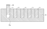
図2に示す保持部12は、剛性材料で構成されていたが、保持部は、可撓性材料で構成されてもよい。図14は、保持部が可撓性材料で構成される生体磁気測定装置の一例を示す模式図である。保持部12’は、図14に示すように、可撓性材料で構成されるため、測定対象に曲面や凹凸があっても、その形状に応じて変形する。よって、保持部12’に保持される磁気センサ11は、その検出面と測定対象との密着面積を大きくすることができ、より精度よく生体磁気の検出が可能となる。
図2に示す保持部12は、剛性材料で構成されていたが、保持部は、可撓性材料で構成されてもよい。図14は、保持部が可撓性材料で構成される生体磁気測定装置の一例を示す模式図である。保持部12’は、図14に示すように、可撓性材料で構成されるため、測定対象に曲面や凹凸があっても、その形状に応じて変形する。よって、保持部12’に保持される磁気センサ11は、その検出面と測定対象との密着面積を大きくすることができ、より精度よく生体磁気の検出が可能となる。
また、図14に示すように、保持部12’の磁気センサ11は、磁気センサ11の位置を検出する位置センサ63や、磁気センサ11の傾きを検出する角度センサ64を備えていてもよい。制御部13では、位置センサ63や角度センサ64の検出結果に基づき、磁気センサ11と測定対象との相対位置を算出し、生体磁気の磁気分布や、電流源推定等を行ってもよい。また、制御部13は、これらを画像情報化して表示装置に表示出力するとよい。
保持部12’に用いられる可撓性材料としては、天然ゴムや合成ゴム等の弾性材料、ポリプロピレン、ポリエチレン、アクリル、ポリカーボネート、塩化ビニル、ポリエチレンテレフタレート(PET)樹脂といった合成樹脂を挙げることができる。なお、保持部12’全体が可撓性材料で構成される必要はなく、例えば、保持孔をそれぞれ固定する複数の固定部が剛性材料で構成され、これら複数の固定部が可撓性材料からなるヒンジにより連結された構成であってもよい。
1 生体磁気測定装置
2 診療台
11 磁気センサ
12 保持部
12a、12b 保持孔
13 制御部
14 メモリ
15 CPU
20 空気圧・油圧機構
21 ポンプ
30 弾性体機構
31 弾性体
40 ネジ機構
41 ネジ軸
42 ネジナット
50 歯車機構
51 歯車
52 噛合部
61 圧力センサ
62 生体電極
63 位置センサ
64 角度センサ
100 生体(被験者)
101 生体情報
2 診療台
11 磁気センサ
12 保持部
12a、12b 保持孔
13 制御部
14 メモリ
15 CPU
20 空気圧・油圧機構
21 ポンプ
30 弾性体機構
31 弾性体
40 ネジ機構
41 ネジ軸
42 ネジナット
50 歯車機構
51 歯車
52 噛合部
61 圧力センサ
62 生体電極
63 位置センサ
64 角度センサ
100 生体(被験者)
101 生体情報
Claims (8)
- 生体磁気を検出する複数の磁気センサと、
前記複数の磁気センサを個別に可動自在に保持する保持孔を有する保持部と、
前記磁気センサを測定対象に対して接離する接離方向へ個別に移動させる移動機構と、を備える生体磁気測定装置。 - 前記移動機構は、空気圧機構、油圧機構、弾性体機構、ネジ機構又は歯車機構の少なくとも一つである、
請求項1に記載の生体磁気測定装置。 - 前記移動機構は、非磁性材料から構成される、
請求項1又は2に記載の生体磁気測定装置。 - 前記移動機構による前記磁気センサの移動量を、外部からの生体情報に基づき制御する制御手段を備える、
請求項1から3のいずれかに記載の生体磁気測定装置。 - 前記磁気センサは、測定対象との接触の有無を検出する接触検出手段をさらに備える、請求項1から4のいずれかに記載の生体磁気測定装置。
- 前記磁気センサは、生体情報を取得する生体情報取得手段をさらに備える、
請求項1から5のいずれかに記載の生体磁気測定装置。 - 前記磁気センサは、測定対象の直下に配される、請求項1から6のいずれかに記載の生体磁気測定装置。
- 前記保持部は、可撓性材料から構成される、請求項1から7のいずれかに記載の生体磁気測定装置。
Priority Applications (4)
| Application Number | Priority Date | Filing Date | Title |
|---|---|---|---|
| JP2018531902A JP7036319B2 (ja) | 2016-08-02 | 2017-08-01 | 生体磁気測定装置 |
| CN201780047125.1A CN109561848B (zh) | 2016-08-02 | 2017-08-01 | 生物磁测量装置 |
| EP17836934.4A EP3494879B1 (en) | 2016-08-02 | 2017-08-01 | Biomagnetism measuring device |
| US16/321,852 US11317843B2 (en) | 2016-08-02 | 2017-08-01 | Biomagnetism measuring device |
Applications Claiming Priority (2)
| Application Number | Priority Date | Filing Date | Title |
|---|---|---|---|
| JP2016-152306 | 2016-08-02 | ||
| JP2016152306 | 2016-08-02 |
Publications (1)
| Publication Number | Publication Date |
|---|---|
| WO2018025829A1 true WO2018025829A1 (ja) | 2018-02-08 |
Family
ID=61073434
Family Applications (1)
| Application Number | Title | Priority Date | Filing Date |
|---|---|---|---|
| PCT/JP2017/027794 Ceased WO2018025829A1 (ja) | 2016-08-02 | 2017-08-01 | 生体磁気測定装置 |
Country Status (5)
| Country | Link |
|---|---|
| US (1) | US11317843B2 (ja) |
| EP (1) | EP3494879B1 (ja) |
| JP (1) | JP7036319B2 (ja) |
| CN (1) | CN109561848B (ja) |
| WO (1) | WO2018025829A1 (ja) |
Cited By (9)
| Publication number | Priority date | Publication date | Assignee | Title |
|---|---|---|---|---|
| WO2019077865A1 (ja) * | 2017-10-16 | 2019-04-25 | 国立大学法人東京医科歯科大学 | 生体磁気計測装置 |
| EP3646782A1 (en) * | 2018-11-02 | 2020-05-06 | Ricoh Company, Ltd. | Biomagnetic-field measurement apparatus, biomagnetic-field measurement method, and magnetic shield box |
| WO2020159118A1 (ko) * | 2019-01-29 | 2020-08-06 | 주식회사 인바디 | 생체 임피던스 측정 장치 및 그 동작 방법 |
| JP2020146408A (ja) * | 2019-03-15 | 2020-09-17 | 株式会社リコー | 磁場検出装置、生体磁場計測システム |
| CN113613555A (zh) * | 2019-01-29 | 2021-11-05 | 殷巴迪股份有限公司 | 生物阻抗测量装置及其操作方法 |
| WO2021246289A1 (ja) * | 2020-06-03 | 2021-12-09 | Tdk株式会社 | 磁場検出装置及び磁場検出装置アレイ |
| WO2021256211A1 (ja) | 2020-06-17 | 2021-12-23 | Tdk株式会社 | 磁気センサアレイ |
| WO2023175773A1 (ja) * | 2022-03-16 | 2023-09-21 | Tdk株式会社 | センサホルダ |
| WO2023204135A1 (ja) * | 2022-04-19 | 2023-10-26 | Tdk株式会社 | 磁気検出システム |
Families Citing this family (14)
| Publication number | Priority date | Publication date | Assignee | Title |
|---|---|---|---|---|
| CN109561848B (zh) * | 2016-08-02 | 2023-03-10 | 国立大学法人东京医科齿科大学 | 生物磁测量装置 |
| EP3629911A4 (en) | 2017-05-22 | 2021-01-20 | Genetesis LLC | MACHINE DIFFERENTIATION OF ANOMALIES IN BIOELECTROMAGNETIC FIELDS |
| US20190038224A1 (en) * | 2017-08-03 | 2019-02-07 | Intel Corporation | Wearable devices having pressure activated biometric monitoring systems and related methods |
| US11134877B2 (en) | 2017-08-09 | 2021-10-05 | Genetesis, Inc. | Biomagnetic detection |
| US12262997B2 (en) | 2017-08-09 | 2025-04-01 | Genetesis, Inc. | Biomagnetic detection |
| US11585869B2 (en) * | 2019-02-08 | 2023-02-21 | Genetesis, Inc. | Biomagnetic field sensor systems and methods for diagnostic evaluation of cardiac conditions |
| CN110151132B (zh) * | 2019-05-16 | 2022-03-18 | 河南中医药大学 | 一种儿科神经触觉检查器 |
| IL298479A (en) | 2020-05-27 | 2023-01-01 | Genetesis Inc | Systems and devices for detecting coronary artery disease using magnetic field maps |
| JP7295516B2 (ja) * | 2020-12-23 | 2023-06-21 | 国立研究開発法人産業技術総合研究所 | 磁気センサ及び生体磁気計測装置 |
| CN112762290B (zh) * | 2020-12-31 | 2022-07-01 | 哈尔滨工业大学 | L型声发射传感器阵列卡具及其检测气体泄漏的试验方法 |
| WO2023105984A1 (ja) * | 2021-12-10 | 2023-06-15 | 株式会社島津製作所 | 生体磁気測定装置 |
| CN114469103B (zh) * | 2022-01-20 | 2024-11-26 | 国仪量子技术(合肥)股份有限公司 | 生物磁检测装置和其控制方法 |
| DE102022209446A1 (de) * | 2022-09-09 | 2024-03-14 | Robert Bosch Gesellschaft mit beschränkter Haftung | Verfahren und Einrichtung zur Bestimmung von Kardiogrammsignalen einer oder mehrerer Personen |
| CN116616775B (zh) * | 2023-05-06 | 2026-03-24 | 北京大学 | 一种测量实验动物生物磁场的可移动式探测装置 |
Citations (3)
| Publication number | Priority date | Publication date | Assignee | Title |
|---|---|---|---|---|
| JPH0291508U (ja) * | 1988-12-29 | 1990-07-20 | ||
| JPH0542120A (ja) * | 1991-08-19 | 1993-02-23 | Chodendo Sensor Kenkyusho:Kk | 生体磁場計測装置 |
| JPH0898820A (ja) * | 1994-09-09 | 1996-04-16 | Ctf Syst Inc | 頭部被覆具 |
Family Cites Families (29)
| Publication number | Priority date | Publication date | Assignee | Title |
|---|---|---|---|---|
| US3758854A (en) * | 1971-03-12 | 1973-09-11 | Ja Zimmerman | Superconductive quantum interference device having two cavities isolated by a superconductive weak link |
| DE3515199A1 (de) * | 1985-04-26 | 1986-11-06 | Siemens AG, 1000 Berlin und 8000 München | Vorrichtung zur messung schwacher magnetfelder mit mehreren gradiometern |
| EP0277283B1 (de) * | 1986-12-09 | 1993-03-31 | Siemens Aktiengesellschaft | Biomagnetische Messeinrichtung |
| US4793355A (en) * | 1987-04-17 | 1988-12-27 | Biomagnetic Technologies, Inc. | Apparatus for process for making biomagnetic measurements |
| US5442289A (en) * | 1989-07-31 | 1995-08-15 | Biomagnetic Technologies, Inc. | Biomagnetometer having flexible sensor |
| US5408178A (en) * | 1991-05-17 | 1995-04-18 | Vanderbilt University | Apparatus and method for imaging the structure of diamagnetic and paramagnetic objects |
| DE4227878A1 (de) * | 1992-08-22 | 1994-02-24 | Philips Patentverwaltung | Abschirmhülle für SQUID-Magnetometer gegen elektromagnetische Störfelder |
| US5494033A (en) * | 1993-06-21 | 1996-02-27 | Biomagnetic Technologies, Inc. | Biomagnetometer with sealed vacuum enclosure and solid conduction cooling |
| US5471985A (en) * | 1994-08-01 | 1995-12-05 | Biomagnetic Technologies, Inc. | Biomagnetometer with whole head coverage of a seated or reclined subject |
| US5817000A (en) * | 1995-09-13 | 1998-10-06 | Souder; James | Magnetic therapy device |
| JPH0984777A (ja) * | 1995-09-25 | 1997-03-31 | Toshiba Corp | 生体磁場計測装置 |
| JP3194695B2 (ja) * | 1995-12-14 | 2001-07-30 | 学校法人金沢工業大学 | 磁気計測装置、その組立方法及び修理方法、並びに磁気計測用診断装置 |
| JP3368287B2 (ja) * | 1996-05-23 | 2003-01-20 | 学校法人金沢工業大学 | 磁気測定装置 |
| US7047059B2 (en) * | 1998-08-18 | 2006-05-16 | Quantum Magnetics, Inc | Simplified water-bag technique for magnetic susceptibility measurements on the human body and other specimens |
| US6496713B2 (en) * | 1996-06-25 | 2002-12-17 | Mednovus, Inc. | Ferromagnetic foreign body detection with background canceling |
| DE19808985B4 (de) * | 1997-03-07 | 2012-06-14 | Hitachi, Ltd. | Verfahren und Vorrichtung zur Biomagnetfeld-Messung |
| JP3712349B2 (ja) * | 2000-07-18 | 2005-11-02 | 独立行政法人科学技術振興機構 | 生存心筋診断装置およびその作動方法 |
| JP4193382B2 (ja) * | 2001-07-19 | 2008-12-10 | 株式会社日立製作所 | 磁場計測装置 |
| US6650107B2 (en) * | 2001-08-23 | 2003-11-18 | Cariomag Imaging, Inc. | Calibrating SQUID channels |
| US7197352B2 (en) * | 2002-08-26 | 2007-03-27 | Tristan Technologies, Inc. | High-resolution magnetoencephalography system, components and method |
| US20090295385A1 (en) * | 2005-05-11 | 2009-12-03 | Audrius Brazdeikis | Magneto Sensor System and Method of Use |
| WO2007099697A1 (ja) | 2006-02-23 | 2007-09-07 | University Corporation, Kanazawa Institute Of Technology | 超伝導磁気測定装置、生体磁気測定方法、生体磁気測定装置用センサ筒カバーおよびシート |
| JP2012095939A (ja) | 2010-11-05 | 2012-05-24 | Konica Minolta Holdings Inc | 生体磁気計測装置および方法 |
| CN102048541B (zh) | 2010-11-15 | 2016-04-06 | 中国科学院上海微系统与信息技术研究所 | 应用于心磁图仪测量的无磁三维机械传动机构 |
| JP5861703B2 (ja) * | 2011-05-20 | 2016-02-16 | コニカミノルタ株式会社 | 磁気センサ及び生体磁気計測システム |
| JP2013124873A (ja) * | 2011-12-13 | 2013-06-24 | Seiko Epson Corp | 磁場測定装置及びセルアレイ |
| JP5839527B1 (ja) * | 2015-02-16 | 2016-01-06 | マグネデザイン株式会社 | 超高感度マイクロ磁気センサ |
| CN109414212B (zh) * | 2016-06-03 | 2023-03-21 | 国立大学法人东京医科齿科大学 | 生物磁测量装置 |
| CN109561848B (zh) * | 2016-08-02 | 2023-03-10 | 国立大学法人东京医科齿科大学 | 生物磁测量装置 |
-
2017
- 2017-08-01 CN CN201780047125.1A patent/CN109561848B/zh active Active
- 2017-08-01 EP EP17836934.4A patent/EP3494879B1/en active Active
- 2017-08-01 US US16/321,852 patent/US11317843B2/en active Active
- 2017-08-01 JP JP2018531902A patent/JP7036319B2/ja active Active
- 2017-08-01 WO PCT/JP2017/027794 patent/WO2018025829A1/ja not_active Ceased
Patent Citations (3)
| Publication number | Priority date | Publication date | Assignee | Title |
|---|---|---|---|---|
| JPH0291508U (ja) * | 1988-12-29 | 1990-07-20 | ||
| JPH0542120A (ja) * | 1991-08-19 | 1993-02-23 | Chodendo Sensor Kenkyusho:Kk | 生体磁場計測装置 |
| JPH0898820A (ja) * | 1994-09-09 | 1996-04-16 | Ctf Syst Inc | 頭部被覆具 |
Non-Patent Citations (1)
| Title |
|---|
| See also references of EP3494879A4 * |
Cited By (17)
| Publication number | Priority date | Publication date | Assignee | Title |
|---|---|---|---|---|
| WO2019077865A1 (ja) * | 2017-10-16 | 2019-04-25 | 国立大学法人東京医科歯科大学 | 生体磁気計測装置 |
| US11666261B2 (en) | 2017-10-16 | 2023-06-06 | National University Corporation Tokyo Medical And Dental University | Biomagnetism measurement device |
| EP3646782A1 (en) * | 2018-11-02 | 2020-05-06 | Ricoh Company, Ltd. | Biomagnetic-field measurement apparatus, biomagnetic-field measurement method, and magnetic shield box |
| WO2020159118A1 (ko) * | 2019-01-29 | 2020-08-06 | 주식회사 인바디 | 생체 임피던스 측정 장치 및 그 동작 방법 |
| CN113613555A (zh) * | 2019-01-29 | 2021-11-05 | 殷巴迪股份有限公司 | 生物阻抗测量装置及其操作方法 |
| US12144600B2 (en) | 2019-01-29 | 2024-11-19 | InBody Co., Ltd. | Bioimpedance measurement device and operation method thereof |
| JP2020146408A (ja) * | 2019-03-15 | 2020-09-17 | 株式会社リコー | 磁場検出装置、生体磁場計測システム |
| JP7521936B2 (ja) | 2020-06-03 | 2024-07-24 | Tdk株式会社 | 磁場検出装置及び磁場検出装置アレイ |
| WO2021246289A1 (ja) * | 2020-06-03 | 2021-12-09 | Tdk株式会社 | 磁場検出装置及び磁場検出装置アレイ |
| JP2021189096A (ja) * | 2020-06-03 | 2021-12-13 | Tdk株式会社 | 磁場検出装置及び磁場検出装置アレイ |
| US12188997B2 (en) | 2020-06-03 | 2025-01-07 | Tdk Corporation | Magnetic field detection device and magnetic field detection device array |
| JP2021196314A (ja) * | 2020-06-17 | 2021-12-27 | Tdk株式会社 | 磁気センサアレイ |
| JP7468178B2 (ja) | 2020-06-17 | 2024-04-16 | Tdk株式会社 | 磁気センサアレイ |
| WO2021256211A1 (ja) | 2020-06-17 | 2021-12-23 | Tdk株式会社 | 磁気センサアレイ |
| US12399235B2 (en) | 2020-06-17 | 2025-08-26 | Tdk Corporation | Magnetic sensor array |
| WO2023175773A1 (ja) * | 2022-03-16 | 2023-09-21 | Tdk株式会社 | センサホルダ |
| WO2023204135A1 (ja) * | 2022-04-19 | 2023-10-26 | Tdk株式会社 | 磁気検出システム |
Also Published As
| Publication number | Publication date |
|---|---|
| US11317843B2 (en) | 2022-05-03 |
| CN109561848A (zh) | 2019-04-02 |
| JP7036319B2 (ja) | 2022-03-15 |
| EP3494879A1 (en) | 2019-06-12 |
| JPWO2018025829A1 (ja) | 2019-07-11 |
| EP3494879A4 (en) | 2019-12-18 |
| EP3494879B1 (en) | 2021-10-06 |
| CN109561848B (zh) | 2023-03-10 |
| US20190167136A1 (en) | 2019-06-06 |
Similar Documents
| Publication | Publication Date | Title |
|---|---|---|
| JP7036319B2 (ja) | 生体磁気測定装置 | |
| JP7075340B2 (ja) | 生体磁気測定装置 | |
| Hu et al. | A cubic 3-axis magnetic sensor array for wirelessly tracking magnet position and orientation | |
| US7834621B2 (en) | Electromagnetic tracking employing scalar-magnetometer | |
| EP3685743B1 (en) | Biomagnetism measurement device | |
| US10791964B2 (en) | Heart rate monitor | |
| JP2003035758A (ja) | 磁場計測装置 | |
| WO2020120924A1 (en) | Apparatus and method(s) in biomagnetic measurements | |
| JP2017070709A (ja) | グラジオセンサ素子およびグラジオセンサ | |
| US11872042B2 (en) | Self-calibration of flux gate offset and gain drift to improve measurement accuracy of magnetic fields from the brain using a wearable neural detection system | |
| US20080204012A1 (en) | Magnetic Tracking System for an Imaging System | |
| Totsu et al. | Three-axis magneto-impedance effect sensor system for detecting position and orientation of catheter tip | |
| US8886282B2 (en) | System and method for measuring magnetocardiogram of small animal | |
| JP7060867B2 (ja) | 生体磁気計測装置及び生体磁気計測システム | |
| JP2020146408A (ja) | 磁場検出装置、生体磁場計測システム | |
| JP7227609B2 (ja) | マーカーコイル及び磁気計測装置 | |
| CN117570826A (zh) | 一种电磁定位方法和系统 | |
| Sun et al. | Using heterogeneous sensory measurements in a compliant magnetic localization system for medical intervention | |
| US20230266411A1 (en) | Sensor and inspection device | |
| Schell et al. | Hall-effect magnetic tracking device for Magnetic Resonance Imaging | |
| JP2023131647A (ja) | 磁気計測装置、磁気計測処理装置および磁気計測処理装置の制御方法 | |
| US12416693B2 (en) | Sensor and inspection device | |
| US11703530B2 (en) | Sensor and inspection device | |
| US20250352274A1 (en) | Tracking and maneuvering using an electromagnetic sensor | |
| Ogata et al. | Articulatory measuring system by using magnetometer and optical sensors |
Legal Events
| Date | Code | Title | Description |
|---|---|---|---|
| 121 | Ep: the epo has been informed by wipo that ep was designated in this application |
Ref document number: 17836934 Country of ref document: EP Kind code of ref document: A1 |
|
| ENP | Entry into the national phase |
Ref document number: 2018531902 Country of ref document: JP Kind code of ref document: A |
|
| NENP | Non-entry into the national phase |
Ref country code: DE |
|
| ENP | Entry into the national phase |
Ref document number: 2017836934 Country of ref document: EP Effective date: 20190304 |