WO2018025409A1 - 車載式炭化処理装置 - Google Patents
車載式炭化処理装置 Download PDFInfo
- Publication number
- WO2018025409A1 WO2018025409A1 PCT/JP2016/073139 JP2016073139W WO2018025409A1 WO 2018025409 A1 WO2018025409 A1 WO 2018025409A1 JP 2016073139 W JP2016073139 W JP 2016073139W WO 2018025409 A1 WO2018025409 A1 WO 2018025409A1
- Authority
- WO
- WIPO (PCT)
- Prior art keywords
- carbonization
- chamber
- vehicle
- flow path
- carbonization chamber
- Prior art date
- Legal status (The legal status is an assumption and is not a legal conclusion. Google has not performed a legal analysis and makes no representation as to the accuracy of the status listed.)
- Ceased
Links
Images











Classifications
-
- C—CHEMISTRY; METALLURGY
- C10—PETROLEUM, GAS OR COKE INDUSTRIES; TECHNICAL GASES CONTAINING CARBON MONOXIDE; FUELS; LUBRICANTS; PEAT
- C10B—DESTRUCTIVE DISTILLATION OF CARBONACEOUS MATERIALS FOR PRODUCTION OF GAS, COKE, TAR, OR SIMILAR MATERIALS
- C10B47/00—Destructive distillation of solid carbonaceous materials with indirect heating, e.g. by external combustion
- C10B47/02—Destructive distillation of solid carbonaceous materials with indirect heating, e.g. by external combustion with stationary charge
Definitions
- the present invention relates to a carbonization apparatus that is configured by a double structure of a carbonization chamber and a carbonization furnace case and can be mounted on a vehicle.
- Such a carbonization processing apparatus includes a combustion chamber that generates hot air, and a box-shaped carbonization chamber that surrounds the five side surfaces excluding the door portion with a heat flow channel having a serpentine structure through which the hot air flows. Hot air is blown and circulated through the entire heat flow path, and the carbonization target object housed in the carbonization chamber is heated indirectly from the outside of the carbonization chamber to carbonize it. The device had to be transported to the place where it occurred.
- Such a conventional carbonization apparatus is formed in a flow path that simply falls and moves from the upper part to the lower part and from one end edge to the multi-end edge on each inner side surface in a square carbonization chamber.
- the inside of the carbonization chamber was heated with radiant heat and carbonized.
- the temperature of the radiant heat emitted from the heat flow path is lower on the downstream side, and the temperature on the ceiling and bottom surfaces becomes lower from the start to the end of the flow path, and the temperature in the square carbonization chamber becomes uneven. Thermal spots were generated, the temperature inside the carbonization chamber became unstable, and the carbonization target could not be thermally decomposed quickly and stably.
- the storage mechanism for the carbonization target object is also a box that is simply stored in the carbonization chamber, so it is impossible to irradiate radiant heat uniformly and quickly, requiring a lot of time for the carbonization process. Due to the structure, there was a lot of leakage of heat and heat loss increased, making it impossible to effectively use heat energy.
- these carbonization treatment apparatuses are mainly made of metal boxes, which increases the weight. Therefore, in order to be able to be mounted on a vehicle, the weight load of each member and structural section of the device on the chassis of the vehicle-mounted trailer. Therefore, it is necessary to devise weight distribution so as to reduce as much as possible.
- the present invention has been made in view of such circumstances, and is configured so that the storage mechanism of the carbonization target object can be uniformly and quickly irradiated with radiant heat uniformly in the carbonization chamber, and the constituent material of the carbonization chamber Even if there is expansion and contraction of members caused by thermal expansion, etc., it is structured to absorb the expansion and contraction margin, and the weight of each device member and structural section can be applied to the chassis of the on-board trailer. It is possible to provide a vehicle-mounted carbonization treatment apparatus that is configured to perform weight distribution so as to be reduced, and that can thermally decompose a carbonization target object quickly and stably while being vehicle-mounted.
- the present invention provides a carbonization furnace case, a carbonization chamber accommodated in the carbonization furnace case, an inner side surface of the carbonization furnace case, and an outer side excluding the carbonization target entry / exit side of the carbonization chamber.
- the carbonization treatment apparatus main body is constituted by the carbonization gas transfer pipe communicated with the carbonization chamber, and the carbonization chamber is placed on a rail laid on the bottom of the carbonization furnace case with a support protrusion protruding from the bottom, and the carbonization chamber
- the support protrusions are loosely fitted in the protrusion support holes formed in the rails while maintaining a certain clearance, and the deformation displacement of the carbonizing chamber resulting from the expansion and contraction of the constituent members due to thermal expansion is configured to be absorbed by the clearance of the protrusion support holes.
- a vehicle-type carbonizing apparatus characterized by being configured to perform mitigation can such weight distribution as possible the weight load of the respective members and structure section of the apparatus main body.
- the storage mechanism of the carbonization object to be stored in the carbonization chamber is configured as a box shape with an open top and the side surface is formed of a wire mesh, and when the four corners of the outer bottom are stacked on each other, Legs are projected so that there is enough space for the lift claws to be inserted between the storage mechanism and the carbonization object stored in the storage mechanism in the carbonization chamber as quickly and uniformly as possible. It is also characterized by being configured to be irradiated.
- the rear half of the trailer chassis is formed so that the front half is positioned slightly below, and the carbonization device main body is disposed in the front and rear in the rear half chassis and a combustion chamber is interposed between the front half and the front half.
- This chassis is also characterized by the fact that an operation related and operation related accessory member is disposed.
- the carbonization furnace case, the carbonization chamber housed in the carbonization furnace case, the inner side surface of the carbonization furnace case and the outer peripheral five side surfaces excluding the carbonization target entry / exit side of the carbonization chamber A heat flow path layer formed between them, a zigzag heat flow path formed in the heat flow path layer, a combustion chamber communicating with the heat flow path via a hot air supply path, and a carbonization chamber and the combustion chamber.
- the carbonization treatment apparatus main body is composed of the carbonization gas transfer pipe and the carbonization chamber, and particularly in such a structure, the carbonization chamber is placed on a rail laid on the bottom of the carbonization furnace case by projecting a support protrusion on the bottom, and the carbonization chamber
- the support protrusions of the carbonization chambers were loosely fitted in the protrusion support holes formed in the rails while maintaining a certain clearance, so that the components of the carbonization chamber were thermally expanded and deformed by high-temperature hot air during the carbonization process. Even if the deformation is displaced, the above configuration absorbs the displacement of the carbonization chamber.
- the storing mechanism of the carbonized object to be stored in the carbonizing chamber is formed in a rectangular box shape with an open top and the side surface is formed of a wire mesh, and at the four corners of the outer bottom portion Since the legs project so as to form a gap that allows the lift claw to be inserted between the lower storage mechanism when stacked on each other, the carbonization target object stored in the storage mechanism in the carbonization chamber is acceptable. It has the effect of being efficiently carbonized by being irradiated with radiant heat as uniformly and rapidly as possible.
- the flow path of hot air is formed between the upper and lower storage mechanisms by the interposition of the legs, and at the same time, the hot air that has permeated through the metal mesh on the side wall rises and flows upward from the metal mesh at the bottom of the upper storage mechanism.
- the hot air efficiently circulates through the gaps between the irregularly shaped carbonized objects that are randomly layered in a random manner to bring hot air into contact with the entire surface of the irregularly shaped carbonized objects as much as possible. There is an effect that the carbonization treatment can be made more efficient.
- the weight distribution of each member and the structural section of the carbonizing device main body is performed on the chassis of the vehicle-mounted trailer so that the weight load can be reduced as much as possible.
- the latter half of the chassis is formed in a slightly lower position with the front half of the chassis, and there are two carbonization device bodies in the front and rear of the chassis in the latter half and a combustion chamber interposed between them. It is possible to reduce the weight load at the connecting part between the trailer and the tractor by applying a heavy weight load of the two carbonizers at a position below the front half, and to smoothly transmit the traction power as much as possible Therefore, there is an effect that there is no hindrance to traction associated with the traveling movement of the carbonizing device on the road.
- operation and operation-related attachments are arranged in the first half of the chassis, making it easier to inspect and maintain the equipment. Since it is at a high position, there is an effect that it is possible to prevent malfunctions and failures of instruments as much as possible without directly receiving vibration shock.
- the present invention relates to a heat flow formed between a carbonization furnace case, a carbonization chamber housed in the carbonization furnace case, and an inner peripheral surface of the carbonization furnace case and an outer peripheral five side surfaces excluding a carbonization target entry / exit side of the carbonization chamber.
- the carbonization chamber body is constructed, and the carbonization chamber is placed on a rail provided with a support projection on the bottom surface and laid on the bottom of the carbonization furnace case, and the support projection of the carbonization chamber is a projection formed on the rail.
- the support hole is loosely fitted with a certain clearance, and the deformation displacement of the carbonization chamber resulting from the expansion and contraction of the component due to thermal expansion is absorbed by the clearance of the protrusion support hole.
- Each member and structure section of the carbonizer It is configured to perform weight distribution as possible to reduce the weight load as much as possible.
- the storage mechanism of the carbonization object to be stored in the carbonization chamber is configured as a box shape with an open top and the side surface is formed of a wire mesh, and when the four corners of the outer bottom are stacked on each other, Legs are projected so that there is enough space for the lift claws to be inserted between the storage mechanism and the carbonization object stored in the storage mechanism in the carbonization chamber as quickly and uniformly as possible. It is characterized by being configured to be irradiated.
- the rear half of the trailer chassis is formed so that the front half is positioned slightly below, and the carbonization device main body is disposed in the front and rear in the rear half chassis and a combustion chamber is interposed between the front half and the front half.
- the chassis has a feature in that an auxiliary member for operation and operation is provided.
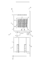
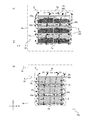
- FIG. 1 is an explanatory diagram showing the concept of the overall configuration of the carbonizing apparatus A.
- 2 is a front view showing the appearance of the carbonization apparatus A, and
- FIG. 3 is a plan sectional view thereof.
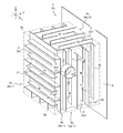
- FIG. 4 is a perspective view of the configuration of the heat flow path 4 surrounding the carbonization chamber 2 as seen from the upper side of one side, and
- FIG. 1 is an explanatory diagram showing the concept of the overall configuration of the carbonizing apparatus A.
- 2 is a front view showing the appearance of the carbonization apparatus A
- FIG. 3 is a plan sectional view thereof.
- FIG. 4 is a perspective view of the configuration of the heat flow path 4 surrounding the carbonization chamber 2 as seen from the upper side of one side, and
- the carbonization apparatus A includes a combustion chamber 6 that generates hot air at the center thereof, and a heat flow path layer 3 through which hot air flows through both upper ends of the combustion chamber 6. 3 'and two carbonization chambers 2 and 2' surrounded by the outer periphery excluding the front surface, and hot air is blown and circulated over the entire heat flow path layers 3 and 3 'to provide carbonization chambers 2 and 2'.
- the carbonization target object accommodated in it is intended to be carbonized by indirectly heating from the outside of the carbonization chamber 2, 2 ′.
- the heat flow path layer 3 is formed with a heat flow path 4 having a serpentine structure, and heat air is regularly distributed around the outer circumferences of the carbonization chambers 2 and 2 ′. Heat is effectively transferred to the carbonization object inside the carbonization chamber 2, 2 ′.
- the structure of the heat flow path 4 is not a simple snake-shaped structure surrounding the outer periphery of the carbonization chamber 2 already proposed by the inventor of the present invention in Japanese Patent Publication No. 2013-533897.
- the hot air flows through the zigzag heat flow paths 4a and 4b, so that the heat energy of the hot air is transmitted to the carbonization object C inside the carbonization chambers 2 and 2 'very effectively and efficiently.
- the carbonization apparatus A that can be mounted on the vehicle by the indirect heating method includes the heat flow paths 4a and 4b that dramatically increase the heat exchange rate such as heating and cooling with the heat transfer fluid or the refrigerant fluid. In order to prevent the harmful effects that occur during heat exchange.
- the carbonization chamber 2 is formed in a box shape as shown in FIGS. 2 to 5 and is housed in a carbonization furnace case 1 similar to the carbonization chamber 2.
- the carbonization furnace case 1 and the carbonization chamber 2 are nested so that the outside air is cut off between the inner side surface of the carbonization furnace case 1 and the outer peripheral five side surfaces of the carbonization chamber 2 excluding the carbonization target entry / exit port 2f side.
- a heat flow path layer 3 whose outer periphery is closed with an outer plate 3 a is formed, and a zigzag heat flow path 4 is formed in the heat flow path layer 3.
- a constant gap is formed between the outer plate 3 a of the heat flow path layer 3 and the inner plate of the carbonization furnace case 1 to form a heat insulating air layer 80.
- the adiabatic air is provided between the door portion 12 and the other peripheral side surfaces excluding the bottom surface.
- the layer 80 is formed with the interposition.
- the inside of the wall thickness of the carbonization furnace case 1 is filled with ceramic wool 81 as a heat insulating material.
- the carbonization chamber 2 has the space which accommodates the carbonization process target object C inside, and the insertion to the carbonization chamber inside of the carbonization process target object C on the front side, and a carbonization process target A carbonization target object entrance / exit 2f having a front opening that enables collection of the object C is formed, and a door portion is pivotally supported by the carbonization process target entry / exit 2f so as to be freely opened and closed.
- the inside of the door portion 12 is filled with a heat insulating material such as ceramic wool 81.
- a heat insulating material such as ceramic wool 81.
- several sheet-like ceramic wool 81 is laminated and formed by through bolts or the like. It is fixed.
- the carbonization chamber 2 is formed in the carbonization chamber 2 in communication with the combustion chamber 6 through the dry distillation gas transfer pipe 7 at the upper center portion of one side surface 2 a.
- the dry distillation gas is recirculated into the combustion chamber 6 to increase the combustion efficiency.
- the storage mechanism 90 for the carbonization object C is removably stored in the carbonization chamber 2.
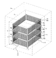
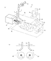
- FIG. 7 is a perspective view showing a state in which the carbonization tray 20 is installed in the carbonization chamber 2.
- FIG. 8A is a side view showing the configuration of the carbonization tray 20
- FIG. 8B is a front view showing the configuration of the carbonization tray 20.
- FIG. 9 is an explanatory view showing a modified example of the carbonizing tray 20.
- the carbonization tray 20 is formed in a rectangular shape slightly smaller than the internal space of the carbonization chamber 2, as shown in FIGS. 3, 7, and 8. 20a, and leg portions 20b are provided at the four corners of the bottom frame 20c, and when the carbonized trays 20 are stacked in several stages, a forklift is disposed between the upper and lower carbonized trays 20 via the leg portions 20b. A space S into which the lift claws are inserted is formed.
- the storage mechanism 90 for the carbonization target C to be stored in the carbonization chamber 2 is formed in a rectangular box shape that is open upward, and at least the side surface is formed by the wire mesh 20a, and the four corners of the outer bottom are mutually attached.
- a leg portion 20b is provided so as to form a gap S that allows the lift claw to be inserted between the lower storage mechanism 90 and the carbonization target object stored in the storage mechanism 90 in the carbonization chamber 2 when stacked.
- C is configured to be irradiated with radiant heat as uniformly and rapidly as possible.
- the carbonization target C stored in the storage mechanism 90 in the carbonization chamber 2 is irradiated with radiant heat as uniformly and rapidly as possible and efficiently carbonized.
- the storage mechanism 90 since the storage mechanism 90 has a laminated structure, irradiation with radiant heat is performed efficiently.
- the flow path of hot air is formed between the upper and lower storage mechanisms 90 by the interposition of the legs 20b, and at the same time, the hot air that has passed through the metal mesh 20a on the side wall rises and the bottom of the upper storage mechanism
- the hot air circulates upward from the wire mesh 20a to form an efficient hot air flow (broken arrows in the figure), and the hot air efficiently circulates through the gaps of the carbonized object C having an irregular shape arbitrarily stacked in an unaligned manner.
- the hot air can be brought into contact with the entire surface of the carbonized object C having an irregular shape as much as possible to improve the efficiency of the carbonization process.
- the carbonizing tray 20 is provided with a convection window drilled at a substantially central position of the bottom portion and a convection window that is connected to the convection window and projects vertically upward.
- a cylindrical hot gas convection cylinder 20d may be provided.
- the carbonization tray 20 configured as described above has the carbonization target C, the bottom, and the hot gas convection cylinder loaded and housed on the bottom so as to surround the outer periphery of the hot gas convection cylinder 20d from the upper opening. While expanding the contact area with 20d, it is possible to further improve the radiant heat efficiency and the convection efficiency of the hot gas inside the carbonizing chamber 2 during heating to form an effective pyrolysis environment of the carbonized object C. Yes.
- FIG. 10A is an explanatory diagram showing the overall configuration of the combustion chamber 6
- FIG. 10B is an explanatory diagram showing the generation state of the swirling flow of hot air inside the combustion chamber 6.
- the combustion chamber 6 has a rectangular parallelepiped shape and is disposed so as to be sandwiched between two front and rear carbonization furnace cases 1 placed on the trailer 31.
- a hot air generating burner 61 is provided substantially at the center of the front side wall 6 a of the combustion chamber 6, and dry distillation from the front position of the upper side wall 6 b of the combustion chamber 6 to the inside of the combustion chamber 6.
- the gas transfer pipes 7 and 7 are projected, and two hot air inflow pipes 5a and 5a ′ and a hot air supply section 62 communicating with the upper part of the upper wall 6b of the combustion chamber 6 are disposed at the rear position.
- a mixed firing portion 63 is formed behind the portion 62.
- the outer peripheral side of the combustion chamber 6 is surrounded by a heat-resistant wall body 64 such as a refractory material, for example, refractory smoke tile or ceramic wool.
- Burner 61 uses kerosene gas, which will be described later, as fuel. Further, the pair of dry distillation gas transfer pipes 7 and 7 ′ protrude from the front position of the upper wall 6 b of the combustion chamber 6 to the inside of the combustion chamber 6.
- 7 c and 7 c ′ are front end openings of the dry distillation gas transfer pipes 7 and 7 ′, and 6 c is the rear side wall of the combustion chamber 6.
- the tip openings 7c and 7c ′ of the pair of dry distillation gas transfer pipes 7 and 7 ′ are connected to the combustion chamber 6 from the dry distillation gas transfer pipes 7 and 7 ′ as shown in FIGS.
- the dry distillation gas and combustion air jetted into the interior strike the left and right side walls 6d and 6d 'in an oblique direction, and generate two swirling flows whose rotational directions are different from each other along both sides of the flame injection direction of the burner 61. It is arranged.
- the co-firing unit 63 is provided as a predetermined space behind the hot air supply unit 62 and surrounded by the rear side wall 6c, the upper and lower side walls, and the left and right side walls 6d and 6d 'of the combustion chamber 6.
- the hot air supply section 62 is a box-shaped member having a predetermined space protruding upward from the rear position of the upper side wall 6b of the combustion chamber 6, and two hot air inflow pipes 5a and 5a 'are connected to the upper part thereof. Has been established.
- the two swirling flows composed of the dry distillation gas and the combustion air having different swirling directions draw a further dry distillation gas and combustion air into the central part of the negative pressure, It moves to the mixed combustion part 63 while burning along the flame injection direction of the burner 61.
- the swirling flow that has moved hits the rear side wall and the left and right side walls of the combustion chamber 6 and is in a turbulent state, so that the mixed combustion is promoted and the dry distillation gas is completely burned to generate hot hot air. It is said.
- a certain amount of this hot air is once accumulated in the hot air supply section 62 at the rear of the upper wall 6b of the combustion chamber 6, and the partial flow rate ratio of the hot air flowing into the two hot air inflow pipes 5a and 5a 'is constant.
- combustion chamber 6 communicates with a heat flow path 4, 4 ′ formed on the outer periphery of the carbonization chamber 2, 2 ′ via hot air inflow pipes 5 a, 5 a ′.
- the hot air generated in the combustion chamber 6 circulates in the hot flow passages 4, 4 ′ formed on the outer periphery of the carbonization chambers 2, 2 ′ via the hot air inflow pipes 5 a, 5 a ′. It will be discharged
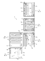
- FIG. 6 is a development view showing a flow process of the two heat flow paths 4a and 4b.
- the heat flow path 4 is formed in a zigzag shape on each of the five side surfaces of the outer periphery of the carbonization chamber 2 by forming a heat flow path layer 3 that is blocked from outside air.
- Each of the heat flow path layers 3 is configured as a continuous first flow path 4a, and the other zigzag heat flow paths on the two side surfaces are configured as continuous second flow paths 4b.
- the start end of the first flow path 4 a and the start end of the second flow path 4 b are both the end openings of the hot air supply path 5 from the combustion chamber 6 that opens to one side surface 2 a of the carbonization chamber 2.
- the terminal end of the first flow path 4 a and the terminal end of the second flow path 4 b are both one of the carbonization chambers 2 on the side opposite to the terminal opening of the hot air supply path 5.
- the hot air discharge passage 10 provided on the side surface 2a is communicated with and joined to the starting end opening 10c to form a zigzag shape, and the flow paths are partitioned by a plurality of partition walls 41.
- first flow path 4a and the second flow path 4b are partitioned by the flow dividing wall 40 provided on the one side surface 2a of the carbonization chamber 2 at a position where the terminal opening 5b of the hot air inflow pipe 5a is halved.
- the first flow path 4a includes a first flow path upstream portion 4a-1 formed on one side surface 2a of the carbonization chamber 2 and a first flow path formed on the upper surface 2b of the carbonization chamber 2. It is formed by the midstream portion 4a-2 and the first flow path downstream portion 4a-3 formed on the other side surface 2c of the carbonization chamber 2.
- the second flow path 4b includes a second flow path upstream portion 4b-1 formed on the back surface 2d of the carbonization chamber 2, and a second flow path downstream portion 4b-2 formed on the lower surface 2e of the carbonization chamber 2. It is formed with.
- each flow path section on the upstream side and the downstream side are in communication with each other.
- the terminal ends of the first flow path 4a and the second flow path 4b are connected to a side wall 6d opposite to the side face 2a provided with the flow dividing wall 40 of the carbonization chamber 2, with a hot air discharge path. 10 is configured to communicate and merge at the start end opening 10c of the discharge pipe 10a.
- the base of the burner 61 of the combustion chamber 6 includes a kerosene tank 14 via a kerosene supply pipe 14a, and a blower 9a for blowing air for combustion via a combustion air feed pipe 13, respectively. There is a continuous connection.
- the middle portion 7b of the dry distillation gas transfer pipe 7 communicating the carbonization chamber 2 and the combustion chamber 6, as shown in FIGS. 1 and 10, combustion air mixed with the combustion air from the blower 9b into the dry distillation gas.
- the feed pipe 16 is connected and functions as an ejector that draws the dry distillation gas from the carbonization chamber 2 into the dry distillation gas transfer pipe 7.
- automatic open / close valves 13 a, 16 a, 14 b, and 7 a are provided in the middle of the combustion air feed pipe 13, kerosene supply pipe 14 a, combustion air feed pipe 16, and dry distillation gas transfer pipe 7, and are operated and controlled by the control panel 15. .
- 15a is a burner control unit
- V is an on-off valve
- T is a thermoelectric band for detecting the carbonization chamber temperature.
- the hot hot air generated in the combustion chamber 6 has a first flow path 4a and a first flow path 4a formed in parallel with a large number of single heat flow paths 42 on the five side surfaces of the outer periphery of the carbonization chamber 2.
- the two flow paths 4b are circulated in a zigzag shape to exchange heat with the carbonization chamber 2.
- the thus formed heat flow path 4 can also be used as a cooling flow path for cooling the carbonization chamber 2 after the carbonization treatment of the carbonization target. That is, in addition to the blower 9 a and the blower 9 b, cold air supplied from a cooling fan 9 c is circulated through the hot flow path 4 through the hot air supply path 5.
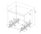
- FIG. 11 is a perspective view showing a mounting structure when the carbonization chamber is accommodated in the carbonization furnace case
- FIG. 12 is a side view thereof.
- Fig.13 (a) shows the trailer 31 and the tractor 32 before mounting the carbonization apparatus A.
- FIG. FIG.13 (b) shows the carbonization processing vehicle 30 carrying the carbonization processing apparatus A, and
- FIG. 14 is the side view.
- the carbonizing apparatus main body 11 according to the carbonizing apparatus A has the front surfaces 2g, 2g ′ and the rear surfaces 2d, 2d ′ of the carbonizing chambers 2, 2 ′ directed in the vehicle left-right direction.
- the structure is loaded on the trailer 31 and is movable by being pulled by the tractor 32.
- the carbonization vehicle 30 has a front side and a rear side of the two carbonization device main bodies 11 directed in the left-right direction of the vehicle, and a combustion chamber 6 is disposed between the carbonization device main bodies 11 to form a chassis 33 of the trailer 31. It is mounted on the top and is configured to be movable by being pulled by the tractor 32.
- the carbonizing apparatus main body 11 in the on-vehicle carbonizing apparatus A is characterized in that, as shown in FIGS. 11 and 12, the carbonizing chamber 2 has a rail 34 installed at a predetermined position on the bottom surface, for example, a lower side. , 34 ′, four support projections 21, 21 ′ are provided so as to be placed on rails 34, 34 ′ laid on the bottom of the carbonization furnace case 1.
- the support protrusions 21 and 21 'of the carbonization chamber 2 are configured to be loosely fitted in the protrusion support holes 34a and 34a' drilled in the rails 34 and 34 'while maintaining a certain clearance.
- the deformation displacement of the carbonizing chamber 2 caused by the expansion and contraction of the constituent members due to the above is configured to be absorbed by the clearances of the protrusion support holes 34a and 34a ′.
- a pair of H steels 35, 35 ′ are laid in parallel at a predetermined interval on the bottom of the carbonization furnace case 1, and both side surfaces of the rails 34, 34 ′ and the H steels 35, 35 are arranged.
- the support piece 35a is abutted and welded over the upper side surface of the '.
- the rails 34 and 34 ′ are arranged on the upper surfaces of a pair of H steels 35 and 35 ′ laid in parallel at a predetermined interval on the bottom of the carbonization furnace case 1.
- the bottom plate of the heat flow path layers 3 and 3 ′ formed in the bottom surface of the carbonization chambers 2 and 2 is a rectangular shape with a predetermined interval therebetween.
- the upper surfaces of the pair of rails 34 and 34 ' are slightly larger than the support protrusions 21 and 21' at positions where they are fitted with the support protrusions 21 and 21 'provided on the bottom surface side of the carbonization chambers 2 and 2'.
- Two protrusion support holes 34a and 34a ′, each of which is a shape groove, are formed.
- the carbonizing chambers 2 and 2 ′ are placed by loosely fitting the supporting projections 21 and 21 ′ on the bottom surface of the carbonizing chamber 2 and 2 ′ into the protruding support holes 34a and 34a ′ of the rails 34 and 34 ′.
- a predetermined clearance is formed between the support protrusion 21 and the protrusion support hole 34a.
- a heat-insulating nonwoven fabric such as ceramic wool may be spread in the space between the protrusion support hole 34a and the support protrusion 21.
- the support protrusions 21 and 21 ′ are formed to have a width of about 9 cm 2 and a length of about 3 cm, and the protrusion support holes 34a and 34a ′ are formed to have a width of about 25 cm 2 and a depth length of about 5 cm, A predetermined clearance can be formed when the support protrusion 21 is loosely fitted into the protrusion support hole 34a.
- the expansion and contraction of the constituent members caused by the thermal expansion of the carbonization chambers 2 and 2 ′ is caused by the clearance between the projection support holes 34a and 34a ′ and the support projections 21 and 21 ′. It is possible to absorb with.
- the above-described configuration is maintained even if the structural frame of the carbonization chambers 2 and 2 ′ is deformed and displaced.
- the displacement of the carbonization chambers 2 and 2 ' can be absorbed to prevent the entire carbonization treatment apparatus A from being distorted, cracks in the components and thermal damage, and the hot air from the combustion chamber 6 can be prevented. It can be set as the carbonization processing apparatus A of the carbonization target C using the thermal energy to the maximum without any omission.
- each member of the two carbonization apparatus main bodies 11 is mounted on the chassis 33 of the vehicle-mounted trailer 31.
- the weight distribution is made so that the weight load of the structural section can be reduced as much as possible.
- the rear half 33b of the chassis 33 of the trailer 31 is formed at a position slightly below the front half 33a.
- the chassis 33 of the rear half 33b is provided with two carbonization device bodies 11, 11 'at the front and rear, and between them.
- the combustion chamber 6 is interposed and the chassis 33 of the front half 33a is also provided with an auxiliary member 91 for operation and operation.
- the operation control device 17 including the control panel 15, the power generation device 18, the kerosene tank 14, and the kerosene pump 14c are disposed on the upper surface of the chassis 33 of the front half 33a.
- the kerosene tank 14 stores kerosene as flame fuel for the burner 61, and is disposed on the upper right side of the chassis 33 in the front half 33a on the tractor 32 side.
- a kerosene pump 14c is disposed adjacent to the kerosene tank 14 at the rear position of the kerosene tank 14 on the upper surface of the chassis 33 in the front half 33a, and an operation control device 17 having a control panel 15 is disposed at the rear position thereof. ing.
- the kerosene pump 14c is controlled by the control panel 15 and supplies a predetermined amount of kerosene from the kerosene tank 14 to the burner 61 through the kerosene supply pipe 14a as described above.
- the power generation device 18 is a part that generates electricity as a power source for the kerosene pump 14c, the operation control device 17, the above-described blower 9, and the hydraulic cylinder 70 of the door 12 described later, and the chassis of the front half 33a. 33 is disposed on the upper left surface of the tractor 32 side.
- two grooves are provided in parallel on the upper surface of the rear half 33b of the chassis 33 at a predetermined interval along the vehicle front-rear direction.
- a pair of liners 36 and 36 ' which are flat plywood, are fitted and laid in the groove so as to be slidable back and forth.
- an L-shaped angle that regulates the front-rear sliding width to a certain level is disposed in the vicinity of both ends of the liners 36, 36 'in the vehicle front-rear direction.
- the carbonization chamber 2 accommodated in the carbonization furnace case 1 via the rails 34 and 34 ′, that is, the carbonization apparatus main body 11 and the combustion chamber 6 disposed therebetween are interposed via the pair of liners 36 and 36 ′.
- the trailer 31 is mounted and fixed side by side at a position where the rear axle load applied to the rear wheel 31a at the vehicle longitudinal direction position becomes the maximum load with respect to the chassis 33 of the trailer 31.
- a predetermined heat insulating space is formed between the carbonizing device main body 11 and the combustion chamber 6 and the chassis 33, and vibrations along the vehicle longitudinal direction are slidably absorbed by the liners 36 and 36 'and carbonized.
- the vibration load applied to the apparatus main body 11 and the combustion chamber 6 is reduced, and the weight load of each member and structural section of the carbonization apparatus main body 11 is reduced as much as possible.
- the rear half 33b of the chassis 33 is located at a position below the front half 33a of the chassis 33. Since the weight load of each carbonizing device main body 11 is applied, the state where the rear end of the chassis 33 swings can be prevented as much as possible, and safer traveling can be performed.
- the operation- and operation-related attachment-related member 91 is disposed in the front half 33a of the chassis 33, so that the inspection and maintenance work of the apparatus can be easily performed, and the traveling vibration caused by the unevenness of the road surface when traveling on the road is the first half. Since 33a is located at a higher position than the rear half 33b, it is possible to prevent malfunctions and failures of the instruments as much as possible without directly receiving vibration shock.
- the carbonization vehicle 30 equipped with the carbonization apparatus A is loaded with a plurality of empty carbonization trays 20 and travels around the waste generation site, and the carbonization target C is accommodated in the carbonization tray 20 at the waste discharge site.
- the carbonization tray 20 is inserted into two or any one of the carbonization chambers 2, 2 ′, the door 12 is closed, and the combustion chamber is passed through the control panel 15 mounted on the carbonization vehicle 30. 6 burner 61 is activated.
- the inside of the carbonization chamber 2 that is shut off from the outside air is consumed with oxygen remaining in the carbonization chamber 2 as the thermal decomposition of the carbonization object C progresses, and the carbonization process is promoted.
- the supply amount of the dry distillation gas and kerosene gas is 40,000 kcl / h to 460,000 kcl / in of the combustion chamber 6 based on the temperature information inside the combustion chamber 6 and the carbonization chamber 2 detected by each thermoelectric band T and the temperature sensor 15b.
- the flow rate is automatically adjusted by the control panel 15 so that each of the carbonization chambers 2 and 2 ′ has a temperature of 0 ° C. or higher and 1000 ° C. or lower.
- the hot air that has flowed into the first flow path 4a and the second flow path 4b by the flow dividing wall 40 flows into the first flow path 4a and the second flow path 4b formed on each side surface.
- the hot air in the first flow path middle portion 4a-2 flows in the zigzag shape through the single heat flow path 42, reaches the first flow path downstream portion 4a-3, and reaches the discharge pipe 10a.
- the hot air in the second flow path upstream portion 4b-1 descends and circulates in the left and right zigzag form, reaches the second flow path downstream part 4b-2, circulates in the single heat flow path 42 in the front and rear zigzag form, One channel reaches the downstream portion 4a-3.
- FIG. 8 As shown in FIG. 8, a hot gas convection phenomenon of dry distillation gas filling the inside of the carbonization chamber 2 occurs due to such a difference in thermal temperature between the side surfaces of the carbonization chamber 2.
- the flow path of the hot air is formed between the upper and lower storage mechanisms 90 by the interposition of the leg portions 20b of the carbonizing tray 20.
- FIG. 8B the hot gas convection of the dry distillation gas inside the carbonization chamber 2 is shown in FIG. 8B from the back surface 2d side ⁇ the upper surface 2b side ⁇ the front surface 2g side ⁇ the lower surface 2e side in the side view shown in FIG.
- convection is caused to flow back from the lower surface 2e side ⁇ the one side surface 2a side ⁇ the upper surface 2b side ⁇ the other side surface 2c.
- the hot air transmitted through the metal mesh 20a on the side wall rises and flows upward from the metal mesh 20a at the bottom of the upper storage mechanism to form an efficient hot air flow (broken arrows in FIG. 8), which is arbitrarily misaligned.
- Hot air can efficiently flow through the gaps between the laminated carbonized objects C having irregular shapes, and the hot air can be brought into contact with the entire surface of the carbonized objects C having irregular shapes as much as possible.
- the convection phenomenon of the dry distillation gas occurs inside the carbonization chamber 2 so that the temperature distribution in the internal space of the carbonization chamber 2 is made substantially uniform.
- the carbonization target C loaded on the carbonization tray 20 is accelerated by thermal decomposition in the oxygen-free carbonization chamber 2 by the radiant heat from the carbonization chamber 2 and the convection heat of the dry distillation gas in the carbonization chamber 2. It becomes a carbide with a very high fixed carbonization rate over time.
- the carbide inside the carbonization chamber 2 can be taken out in a short time by operating and quenching the carbonization apparatus A.
- the carbonization object C carbonized in the carbonization chamber can be lifted up with the forklift lift claw together with the carbonization tray 20 and taken out of the carbonization chamber.
- the present invention is also characterized by the sealing mechanism of the door 12 described below.
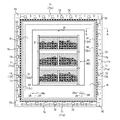
- FIG. 15 shows the configuration of the carbonizing device main body 11 in the closed state
- FIG. 16 shows the configuration of the carbonizing device main body 11 in the opened state.
- the hot air gas (dry distillation gas) in the carbonization chamber 2 is leaked by improving the sealing structure between the door portion 12 and the openings 1 a and 2 f of the carbonization furnace case 1 and the carbonization chamber 2. It is comprised so that a carbonization process with good thermal efficiency can be performed.
- the carbonization furnace case 1 and the carbonization chamber 2 accommodated in the carbonization furnace case 1 are such that one of the outer peripheral hexahedrons is opened for taking in and out the carbonization object C, and an opening 1a of the carbonization furnace case 1 and carbonization are performed.
- blocking with external air is pivotally supported by the chamber opening part 2f so that opening and closing is possible.
- FIG. 17 shows a sealing structure in front of the carbonization furnace case 1.
- FIG. 18 is a cross-sectional view taken along the line AA of the carbonizing apparatus main body 11 shown in FIG. 17, and FIGS. 18 (a) and 18 (b) show the opened state and the closed state, respectively.
- the carbonization chamber flange 2 i is sandwiched between the pressing flange 12 a at the peripheral edge of the door portion 12 and the peripheral edge surface 1 b of the opening portion of the carbonization furnace case 1, thereby fixing the carbonization chamber 2.
- the opening 2f of the carbonization chamber 2 and the opening 1a of the carbonization furnace case 1 are configured to be sealable by a pressing flange 12a on the periphery of the door 12.
- a steel bar 12c having a U-shaped cross section projects from the end edge 12b of the door 12, and a buffer-attached rope for the door is inserted into the bar 12c. 12d is inserted and laid, and the door portion buffer contact rope 12d is stretched around the periphery of the door portion 12.
- the buffering rope 12d is made of ceramic wool, can maintain strength by a heat resistance function against heat as well as an adhesion function by a certain elastic force, and can obtain a heat insulation effect.
- the edge 12b of the door portion is closed. Can be pressure-bonded to the front end surface 1e of the carbonization furnace case so that the heat loss of the heat energy in the carbonization chamber is minimized.
- a steel bar 1c having a U-shaped cross section is provided on the peripheral edge surface 1b of the opening so as to protrude into the bar 1c.
- a furnace buffer close-contact rope 1d is fitted into the furnace buffer close-contact rope 1d around the periphery of the carbonization furnace case 1.
- the rope material is made of ceramic wool.
- the leading edge 12e of the door 12 can be crimped to the front end surface 1e of the carbonization furnace case when the door is closed, and the impact of the heavy door 12 when the door is closed can be buffered.
- the sealing function of the carbonization furnace case opening 1a can be achieved.
- the close-contact section rope 51 is disposed at a position corresponding to the door-side buffer close-contact rope 12 d stretched around the edge of the door 12, and the door-part buffer close-contact Between the rope 12d, a flange 2i on the periphery of the carbonization chamber 2 is interposed. Even when a weight load is applied to the pressing flange 12a on the periphery of the door when the door is closed, the two superposed ropes 12d, 51 overlapped with the weight load. Therefore, the door can be firmly closed and securely closed.
- FIG. 19A shows a state in which the door piece 12g of the door 12 and the tapered piece 72 of the carbonization furnace case 1 are open, and FIG. 19B shows that the pieces 72 and 12g are fitted to each other.
- FIG. 19C shows a taper fitting mechanism of the tops 72 and 12g by sliding of the top shaft 71 in plan view.
- left and right vertical frame shafts 71a and 71b are formed in the left and right vertical direction
- upper and lower horizontal frame shafts 71c and 71d are formed in the vertical and horizontal directions at the periphery of the opening of the carbonization furnace case 1.
- Each is slidably installed.
- a hydraulic cylinder 70 is connected to the end of the coma shaft 71, and the coma shaft 71 is configured to slide up and down and left and right by the operation of the hydraulic cylinder 70.
- a plurality of tapered pieces 72 are continuously connected to the piece shaft 71 at a predetermined interval, and as shown in FIG. 19, the tapered pieces 72 of the piece shaft 71 and the peripheral edge portion of the door portion 12 are also closed when the door is closed.
- a door top 12g protrudes at a substantially corresponding position.
- these tops 72 and 12g are formed such that their contact surfaces are tapered and tapered, and the tapered top 72 is formed narrowed upward.
- the door top piece 12g is formed in a tapered slope opposite to the tapered piece 72.
- the abutting sliding surfaces of the tops 72 and 12g form inclined surfaces in opposite directions, and as shown in FIG. 19 (c), the sliding of the top shaft 71 when the door is closed causes the tops 72 and 12g to slide.
- the door peripheral portion 12h can be brought into close contact with the opening peripheral surface 1b of the carbonization furnace case 1 by the taper function of the tops 72 and 12g.
- the door portion 12 can be brought into close contact with the carbonization chamber 2 and the openings 1a and 2f of the carbonization furnace case 1 through the contact section rope 51, the door buffer contact rope 12d, the furnace buffer contact rope 1d, and the like.
- the abutment function of the tops 72 and 12g can also achieve a stronger adhesion function, and this structure reduces heat leakage as much as possible and enables efficient and effective use of thermal energy for carbonization. Become.
- the carbonization furnace case 1, 1 ′, the carbonization chamber 2, 2 ′ accommodated in the carbonization furnace case 1, 1 ′, and the carbonization furnace case 1 A heat flow path layer 3, 3 'formed between the 1' inner side surface and the outer peripheral five side surfaces excluding the carbonization object inlet / outlet port 2f, 2f 'side of the carbonization chamber 2, 2'; Zigzag-shaped heat flow path 4, 4 ′ formed in 3 ′, combustion chamber 6 communicating with heat flow paths 4, 4 ′ via hot air supply paths 5, 5 ′, carbonization chamber 2, 2 ′ and combustion chamber 6
- the carbonization chambers 2 and 2 ' have support protrusions 21 and 21 on the bottom surface. Is placed on the rails 34, 34 'laid on the bottom of the carbonization furnace case 1, 1' and the support protrusion 2 of the carbonization chamber 2, 2 ' , 21 'is formed by loosely fitting with protrusion support holes 34a, 34a' drilled in the rails 34, 34 'while maintaining a certain clearance, so that the carbonization chambers 2, 2' are heated by hot air during the carbonization process.
- the above configuration absorbs the displacement of the carbonization chambers 2 and 2 ′ and slides the carbonization chambers 2 and 2 ′. It is possible to prevent distortion of the entire carbonizing apparatus A, cracks in the components, and thermal damage, and in other words, the hot air from the combustion chamber 6 can be effectively used without leaking to maximize the use of thermal energy.
- the carbonization treatment object C can be carbonized.
- the storage mechanism 90 for the carbonization object C stored in the carbonization chambers 2 and 2 ′ is formed in a rectangular box shape with an open top and the side surfaces are formed by the wire mesh 20a, and at the four corners of the outer bottom. Since the leg portions 20b project so as to form a gap S between which the lift claws can be inserted with the lower storage mechanism 90 when they are stacked on each other, the storage mechanism 90 is provided in the carbonization chambers 2, 2 ′.
- the carbonized object C stored in the container is irradiated with radiant heat as uniformly and rapidly as possible and uniformly and carbonized efficiently.
- a hot air circulation channel is formed between the upper and lower storage mechanisms 90 by the interposition of the legs 20b, and simultaneously, the hot air transmitted through the side wall metal mesh 20a rises upward from the metal mesh at the bottom of the upper storage mechanism 90.
- the hot air is efficiently circulated through the gaps between the carbonized objects C of irregular shapes arbitrarily stacked in an unaligned manner, and can be applied to the entire surface of the carbonized objects C of irregular shapes.
- the efficiency of carbonization can be improved by bringing hot air into contact as much as possible.
- the chassis 33 of the vehicle-mounted trailer 31 is configured to perform weight distribution so as to reduce the weight load of each member and structural section of the carbonizing apparatus main bodies 11 and 11 ′ as much as possible.
- the front half 33a is formed at a slightly lower position
- the chassis 33 of the rear half 33b is provided with two carbonizer main bodies 11 and 11 'at the front and rear, with the combustion chamber 6 interposed therebetween. Since the heavy load of the two carbonizing apparatus main bodies 11 and 11 ′ is applied to the rear half 33 b of the chassis 33 at a position lower than the front half 33 a, the weight load at the connecting portion between the trailer 31 and the tractor 32 is reduced. Since the reduction can be achieved and the traction power can be transmitted as smoothly as possible, there is an effect that the traction associated with the traveling movement of the carbonizing apparatus on the road has no problem.
- the rear half 33b of the chassis 33 is located at a position below the front half 33a of the chassis 33. Since the weight loads of the individual carbonizing device main bodies 11 and 11 ′ are applied, the state in which the rear end of the chassis 33 swings can be prevented as much as possible, and safer traveling can be performed.
- the operation- and operation-related attachment-related member 91 is disposed in the front half 33a of the chassis 33, so that the inspection and maintenance work of the apparatus can be easily performed, and the traveling vibration caused by the unevenness of the road surface when traveling on the road is the first half. Is higher than the latter half, so that it is possible to prevent malfunctions and failures of instruments as much as possible without directly receiving vibration shock.
- the present invention is configured so that the storage mechanism of the carbonization target object can be uniformly and quickly irradiated with radiant heat uniformly in the carbonization chamber, and the expansion and contraction of the member caused by the thermal expansion of the constituent material of the carbonization chamber, etc. Even if there is, it is constructed so that it can absorb the expansion and contraction margin, and weight distribution is performed so that the weight load of each component of the device and the structural section can be reduced as much as possible to the chassis of the vehicle-mounted trailer. It is possible to provide a vehicle-mounted carbonization apparatus that can quickly and stably thermally decompose a carbonized object while being vehicle-mounted.
- a Car-mounted carbonization treatment apparatus Carbonization furnace case 2 Carbonization chamber 3 Heat flow path layer 4 Heat flow path 5 Hot air supply path 6 Combustion chamber 7 Dry distillation gas transfer pipe 9 Blower 10 Hot air discharge path 11 Carbonization furnace main body 12 Door part 13 Combustion air feed Pipe 14 Kerosene tank 15 Control panel 16 Combustion air feed pipe 17 Cooling air feed pipe 80 Insulated air layer 30 Carbonized vehicle 32 Tractor 33 Chassis 91 Accessories
Landscapes
- Chemical & Material Sciences (AREA)
- Engineering & Computer Science (AREA)
- Combustion & Propulsion (AREA)
- Materials Engineering (AREA)
- Oil, Petroleum & Natural Gas (AREA)
- Organic Chemistry (AREA)
- Processing Of Solid Wastes (AREA)
Abstract
炭化処理設備をコンパクト化して炭化処理対象物の発生現場で短時間で安定して炭化処理対象物を炭化処理することができ車載式炭化処理装置に関する。 炭化室は底面に支持突起を突設して炭化炉ケース底部に敷設したレール上に載置すると共に、炭化室の支持突起はレールに穿設した突起支持孔に一定のクリアランスを保持して遊嵌し、熱膨張による構成部材の伸縮から生じる炭化室の変形変位を突起支持孔のクリアランスで吸収すべく構成し、しかも、車載用のトレーラのシャーシに炭化装置本体の各部材や構造セクションの重量負荷を可及的に軽減できるような重量配分を行うように構成したことを特徴とする車載式炭化処理装置を提供するものである。
Description
本発明は、炭化室と炭化炉ケースとの二重構造により構成して車載可能にした炭化処理装置に関する。
一般的に、各種産業界、畜産業界、下水処理場及び医療関係機関などの種々の業界で日々排出される有機系の廃棄物(以下、単に「炭化処理対象物」と言う。)の処理は、環境に配慮しつつ一定の基準に即して処理する必要があり、これらの業界において大きな負担となっていた。
これに対し、炭化処理対象物を無酸素状態で間接的に加熱することで熱分解し、固定炭素として資源化可能とする炭化炉処理装置が提案されている(例えば、特許文献1参照。)。
このような炭化処理装置は、熱風を発生させる燃焼室と、熱風が流通する蛇型構造の熱流路で扉部部分を除いた五側面を囲繞した箱型形状の炭化室とを備えており、熱風を熱流路全体に送風循環させ、炭化室内に収容した炭化処理対象物を炭化室外部から間接的に加熱して炭化するもので、通常地上に載置固定するために移動して炭化材料の発生する箇所まで装置を搬送しなければならないものであった。
かかる従来の炭化処理装置は、方形状の炭化処理室内の各内側面において上部から下部、一端縁から多端縁に至るまで単純に熱降下や熱移動する流路に形成し、各面にジグザグ状の熱流路を形成して炭化室の内部を輻射熱で加熱して炭化処理するものであった。
従って、熱流路から発散される輻射熱の温度は側面では下流側ほど低い温度となり、天井面や底面では流路始端から終端に至るに従って低い温度となり、方形状の炭化処理室内の温度は不均一となり熱斑が発生して炭化室内部の温度が不安定となり、炭化処理対象物を迅速且つ安定して熱分解をすることができなかった。
炭化処理対象物の収納機構も単に炭化室に収納するだけの箱体であるため均一に迅速に輻射熱を万遍なく照射できず炭化処理に多大の時間を要し、また炭化室を含む全体の構造上熱の遺漏が多く熱ロスが大きくなり熱エネルギーを有効に活用できなかった。
また、一般に炭化装置においては構造の密閉機能を高める必要があるが、従来の炭化室の構成材料では熱膨張に伴う部材の伸縮を生起して思わぬ個所の接合部分にクリアランスを生起して炭化に必要な熱が遺漏し熱の有効な利用が行えなかった。
すなわち、炭化室の各側面で温度分布が不均一となると偏奇して一部に異常な高温エリアを形成することになりこのような各側面における不均一な熱分布は局所的な熱斑を発生させて方形状の炭化処理室壁の熱膨張差を過剰とする。その結果上記するように構造的な接合部分においてクリアランスを生起して熱の遺漏が発生し膨大な熱損失を生起し炭化処理の効率化を妨げる恐れがあった。
しかも、これらの炭化処理装置は金属の箱体を主体としているため重量的に大となり、従って、車載可能に構成するためには車載用のトレーラのシャーシに装置の各部材や構造セクションの重量負荷を可及的に軽減できるように重量配分の工夫を行う必要が生じる。
本発明は、斯かる事情に鑑みてなされたものであって、炭化処理対象物の収納機構を炭化室内において均一で迅速に万遍なく輻射熱を照射できるように構成すると共に、炭化室の構成材料等の熱膨張によって生起する部材の伸縮があっても構造的に伸縮のマージンを吸収できるように構成し、しかも、車載用のトレーラのシャーシに装置の各部材や構造セクションの重量負荷を可及的に軽減できるような重量配分を行うように構成し、車載式でありながら炭化処理対象物を迅速且つ安定して熱分解をすることができる車載式炭化処理装置を提供するものである。
上記従来の課題を解決するために、この発明は、炭化炉ケースと、炭化炉ケース内に収納された炭化室と、炭化炉ケース内側面と炭化室の炭化処理対象物出入口側を除いた外周五側面との間に形成した熱流路層と、熱流路層に形成したジグザグ状の熱流路と、熱流路に熱風供給路を介して連通した燃焼室と、炭化室と燃焼室との間に連通介設した乾留ガス移送管とより炭化処理装置本体を構成し、しかも、炭化室は底面に支持突起を突設して炭化炉ケース底部に敷設したレール上に載置すると共に、炭化室の支持突起はレールに穿設した突起支持孔に一定のクリアランスを保持して遊嵌し、熱膨張による構成部材の伸縮から生じる炭化室の変形変位を突起支持孔のクリアランスで吸収すべく構成し、しかも、車載用のトレーラのシャーシに炭化装置本体の各部材や構造セクションの重量負荷を可及的に軽減できるような重量配分を行うように構成したことを特徴とする車載式炭化処理装置を提供するものである。
また、炭化室内に収納する炭化処理対象物の収納機構は、上方開放の方形状の箱型に構成すると共に側面は金網で形成し、しかも、外底部の四隅には互いに積層した場合に下方の収納機構との間にリフト爪が挿入できるだけの間隙が形成されるように脚部を突設し、炭化室内において収納機構に収納した炭化処理対象物に可及的均一迅速にかつ万遍なく輻射熱が照射されるように構成したことにも特徴を有する。
また、トレーラのシャーシの後半部を前半部をよりやや下方位置に形成し、後半部のシャーシには二個の炭化装置本体を前後に配設すると共にその間に燃焼室を介設し、前半部のシャーシには操作及び作動関係の付属関連部材を配設したことにも特徴を有する。
請求項1の発明によれば、炭化炉ケースと、炭化炉ケース内に収納された炭化室と、炭化炉ケース内側面と炭化室の炭化処理対象物出入口側を除いた外周五側面との間に形成した熱流路層と、熱流路層に形成したジグザグ状の熱流路と、熱流路に熱風供給路を介して連通した燃焼室と、炭化室と燃焼室との間に連通介設した乾留ガス移送管とより炭化処理装置本体を構成しており、特にかかる構造において、炭化室は底面に支持突起を突設して炭化炉ケース底部に敷設したレール上に載置すると共に、炭化室の支持突起はレールに穿設した突起支持孔に一定のクリアランスを保持して遊嵌したために、炭化処理中に高温の熱風により炭化室の構成部材に熱膨張変形を生じ炭化室の構成枠が変形変位しても上記の構成が炭化室の変位を吸収して炭化室の摺動を促し炭化処理装置全体のひずみや構成部材の亀裂や熱損壊を防止することができ、翻っては燃焼室からの熱風を遺漏することなく有効に利用して熱エネルギーを最大限に活用した廃棄物の炭化処理装置を提供することができる効果がある。
請求項2の発明によれば、炭化室内に収納する炭化処理対象物の収納機構は、上方開放の方形状の箱型に構成すると共に側面は金網で形成し、しかも、外底部の四隅には互いに積層した場合に下方の収納機構との間にリフト爪が挿入できるだけの間隙が形成されるように脚部を突設したことにより、炭化室内において収納機構に収納された炭化処理対象物は可及的均一迅速にかつ万遍なく輻射熱が照射され効率よく炭化処理される効果がある。
更には、脚部の介在によって上下の収納機構の間に熱風の流通流路が形成され、同時に側壁の金網を透過した熱風は上昇して上層の収納機構底部の金網から上方に流通し効率的な熱風の流通を形成し、任意に不整列に積層した不定形状の炭化処理対象物の間隙を熱風が効率よく流通して不定形状の炭化処理対象物の全面に可及的に熱風を接触させ炭化処理の効率化を行うことができる効果がある。
請求項3の発明によれば、車載用のトレーラのシャーシに炭化装置本体の各部材や構造セクションの重量負荷を可及的に軽減できるような重量配分を行うように構成し、特にトレーラのシャーシの後半部を前半部をよりやや下方位置に形成し、後半部のシャーシには二個の炭化装置本体を前後に配設すると共にその間に燃焼室を介設しているので、シャーシ後半部に前半部より下位置で二個の炭化装置本体の大重量負荷をかけてトレーラとトラクタとの連結部分における重量負荷の軽減を図ることができ、可及的に牽引動力の伝達を円滑に行うことができるために炭化装置の路上走行移動に伴う牽引に何ら支障がない効果がある。
しかも、トレーラとトラクタとを連結して車両全体を長大化させて路上走行を行う場合に路上カーブのハンドリングに際し、シャーシの後半部でシャーシ前半部より下位置において二個の炭化装置本体の重量負荷をかけているので、シャーシの最後尾が振れる状態を可及的に防止することができることになりより安全な走行を行うことができる効果がある。
また、シャーシ前半部に操作及び作動関係の付属関連部材を配設したことにより、装置の点検やメンテナンス作業が行い易く、また路上走行時の路面の凹凸に伴う走行振動が前半部が後半部より高い位置にあるため振動衝撃を直接に受けることなく計器類の誤作動や故障を可及的に防止することができる効果がある。
本発明は、炭化炉ケースと、炭化炉ケース内に収納された炭化室と、炭化炉ケース内側面と炭化室の炭化処理対象物出入口側を除いた外周五側面との間に形成した熱流路層と、熱流路層に形成したジグザグ状の熱流路と、熱流路に熱風供給路を介して連通した燃焼室と、炭化室と燃焼室との間に連通介設した乾留ガス移送管とより炭化処理装置本体を構成し、しかも、炭化室は底面に支持突起を突設して炭化炉ケース底部に敷設したレール上に載置すると共に、炭化室の支持突起はレールに穿設した突起支持孔に一定のクリアランスを保持して遊嵌し、熱膨張による構成部材の伸縮から生じる炭化室の変形変位を突起支持孔のクリアランスで吸収すべく構成し、更に、車載用のトレーラのシャーシに炭化装置本体の各部材や構造セクションの重量負荷を可及的に軽減できるような重量配分を行うように構成している。
また、炭化室内に収納する炭化処理対象物の収納機構は、上方開放の方形状の箱型に構成すると共に側面は金網で形成し、しかも、外底部の四隅には互いに積層した場合に下方の収納機構との間にリフト爪が挿入できるだけの間隙が形成されるように脚部を突設し、炭化室内において収納機構に収納した炭化処理対象物に可及的均一迅速にかつ万遍なく輻射熱が照射されるように構成したことに特徴を有する。
また、トレーラのシャーシの後半部を前半部をよりやや下方位置に形成し、後半部のシャーシには二個の炭化装置本体を前後に配設すると共にその間に燃焼室を介設し、前半部のシャーシには操作及び作動関係の付属関連部材を配設したことに特徴を有する。
以下、実施形態に係る間接加熱方式の車載式炭化処理装置A(以下、単に炭化処理装置Aとも言う。)について図面を参照しながら説明する。図1は、炭化処理装置Aの全体構成の概念を示す説明図である。また、図2は、炭化処理装置Aの外観を示す正面図であり、図3は、その平断面図である。また、図4は、炭化室2を囲繞する熱流路4の構成を一側面上方側からみた斜視図であり、図5は、他側面下方側からみた斜視図である。
本発明に係る炭化処理装置Aは、図1~図3に示すように、その中央部に熱風を発生させる燃焼室6と、燃焼室6の上方両端側に熱風が流通する熱流路層3、3’で正面を除いた外周を囲まれた2つの炭化室2、2’と、を備えており、熱風を熱流路層3、3’全域に亘って送風循環させ、炭化室2、2’内に収容した炭化処理対象物を炭化室2、2’外部から間接的に加熱して炭化しようとするものである。
熱流路層3には、図4及び図5に示すように、蛇型構造の熱流路4が形成されており、炭化室2、2’の外周で熱風を規則的に流通させて熱エネルギーを効果的に炭化室2、2’内部の炭化処理対象物に伝熱する。
特に、この熱流路4の構造は、本願発明者が特表第2013-533897号で既に提案している炭化室2の外周を囲む単純な蛇型構造としているのではなく、1つの炭化室2の外周において2つの熱流路4a、4bに分け、それぞれの上流側から下流側にかけて炭化室2の五側面に熱流路4a、4bを一定の規則に従ってジグザグ状に形成している。
そして、このようなジグザグ状の熱流路4a、4b内を熱風が流通することにより、熱風の熱エネルギーが炭化室2、2’内部の炭化処理対象物Cに極めて効果的且つ効率よく伝わる。
また、ジグザグ状の熱流路4a、4bに冷風を流通させることで高熱状態にある炭化室2、2’を急速冷却すると炭化室2、2’の熱斑に起因した偏奇ひずみや劣化を防止しつつ炭化室2、2’側壁の均一な熱収縮を実現する。
このように間接加熱方式で車載可能な炭化処理装置Aは、熱媒流体又は冷媒流体との間で加熱や冷却といった熱交換率を飛躍的に上昇させる熱流路4a、4bを炭化室2、2’に対し一定の規則性に従って備え、熱交換時に発生する弊害を防止している。
炭化室2は、図2~図5に示すように、ボックス形状に形成しており、炭化室2と相似形の炭化炉ケース1内に収納されている。
すなわち、炭化炉ケース1と炭化室2とで入れ子構造とし、炭化炉ケース1内側面と炭化室2の炭化処理対象物出入口2f側を除いた外周五側面との間に外気と遮断するように外周を外側板3aで閉塞した熱流路層3を形成し、この熱流路層3にジグザグ状の熱流路4を形成している。
更には、図1及び図3に示すように、熱流路層3の外側板3aと炭化炉ケース1の内側板との間には一定の間隙を形成して断熱空気層80としている。
従って、炭化炉ケース1とその内部に入れ子構造で収納した炭化室2、すなわち熱流路層3の外側板3aとの間には扉部12と底面を除いた他の周側面の間に断熱空気層80が介在して形成されていることになる。
また、炭化炉ケース1の壁厚内部には断熱素材としてのセラミックスウール81を充填している。
また、図2及び図3に示すように、炭化室2は、内部に炭化処理対象物Cを収容する空間と、正面側に炭化処理対象物Cの炭化室内部への装入及び炭化処理対象物Cの収集を可能とする正面開口の炭化処理対象物出入口2fを形成し、炭化処理対象物出入口2fには扉部が開閉自在に枢支されている。
また、かかる扉部12の内部には、図3に示すように、セラミックウール81などの断熱素材が充填されており、実際にはシート状のセラミックウール81を数枚積層して貫通ボルトなどにより固定している。
また、炭化室2は、図1及び図4に示すように、その一側面2aの中央部上部で乾留ガス移送管7を介して燃焼室6内と連通連設し炭化室2内で生成した乾留ガスを燃焼室6内に還流して高燃焼効率化を図っている。
かかる炭化室2に内部には炭化処理対象物Cとして、例えば廃棄材木や日用品のうち有機材料でできている廃棄物などが収納される。そのために、炭化室2内には炭化処理対象物Cの収納機構90を取り出し自在に収納する。
以下、図3、図7~図9を参照しながら、炭化室2に収納する収納機構90について具体的に説明する。すなわち、収納機構90は、方形箱型の炭化トレイ20として構成している。図7は、炭化トレイ20を炭化室2に装入設置した状態を示す斜視図である。また、図8(a)は、炭化トレイ20の構成を示す側面図であり、図8(b)は、炭化トレイ20の構成を示す正面図である。また、図9は、炭化トレイ20の変形例を示す説明図である。
炭化トレイ20は、図3、図7及び図8に示すように、炭化室2内部空間よりやや小さい方形状に形成しており、上方開放の箱型とし方形組み付けのフレームの周壁や底面は金網20aで構成し、底部フレーム20cの四隅には脚部20bを突設して炭化トレイ20を数段に重ねて積層したときに脚部20bを介して上下段の炭化トレイ20の間にフォークリフトのリフト爪が差し込まれる空間Sが形成されるように構成している。
すなわち、炭化室2内に収納する炭化処理対象物Cの収納機構90は、上方開放の方形状箱型に構成すると共に、少なくとも側面は金網20aで形成し、しかも、外底部の四隅には互いに積層した場合に下方の収納機構90との間にリフト爪が挿入できるだけの間隙Sが形成されるように脚部20bを突設し、炭化室2内において収納機構90に収納した炭化処理対象物Cに可及的均一迅速にかつ万遍なく輻射熱が照射されるように構成している。
このようにして炭化室2内において収納機構90に収納された炭化処理対象物Cは可及的均一迅速にかつ万遍なく輻射熱が照射され効率よく炭化処理される。
特に、かかる収納機構90の積層構造としたために輻射熱の照射が効率よく行われる。例えば、図8に示すように、脚部20bの介在によって上下の収納機構90の間に熱風の流通流路が形成され、同時に側壁の金網20aを透過した熱風は上昇して上層の収納機構底部の金網20aから上方に流通し効率的な熱風の流通(図中、破線矢印)を形成し、任意に不整列に積層した不定形状の炭化処理対象物Cの間隙を熱風が効率よく流通して不定形状の炭化処理対象物Cの全面に可及的に熱風を接触させ炭化処理の効率化を行うことができる効果がある。
また、図9に示すように、収納機構90としての変形例として、炭化トレイ20は、底部の略中央位置に穿設した対流窓と、同対流窓に連設して鉛直上方向に突設した筒状の熱ガス対流筒20dとを設けて構成してもよい。
このように構成した炭化トレイ20は、その上部開口から熱ガス対流筒20dの外周を囲むように底部に炭化処理対象物Cを積載収容することで炭化処理対象物Cと底部と熱ガス対流筒20dとの接触面積を拡大すると共に、加熱時における炭化室2内部の輻射熱効率や熱ガスの対流効率をさらに向上させて炭化処理対象物Cの効果的な熱分解環境を形成することを可能としている。
次に、図1及び図10を参照しつつ、燃焼室6の構成について説明する。図10(a)は、燃焼室6の全体構成を示す説明図であり、図10(b)は、燃焼室6内部における熱風の旋回流の発生状態を示す説明図である。
燃焼室6は、直方体形状でトレーラ31上に載置した前後二個の炭化炉ケース1の間に挟まれるように配設されている。
図10(a)に示すように、燃焼室6の前側壁6a略中央には熱風生成用のバーナー61が設けられ、燃焼室6の上側壁6bの前部位置から燃焼室6内方に乾留ガス移送管7、7が突出され、燃焼室6の上側壁6bの後部位置には2つの熱風流入管5a、5a’及びその上部で連通する熱風送気部62が配設され、熱風送気部62後方には混焼部63が形成されている。なお、燃焼室6の外周側は、図1に示すように、耐火材料、例えば耐火煙瓦やセラミックウール等の耐熱性壁体64で囲繞している。
バーナー61は、後述する灯油ガスを燃料とする。また、一対の乾留ガス移送管7、7’は、燃焼室6の上側壁6bの前部位置から燃焼室6の内方にそれぞれ突出している。図10(a)中、7c、7c’は乾留ガス移送管7、7’の先端開口部、6cは燃焼室6の後側壁を示す。
すなわち、一対の乾留ガス移送管7、7’の先端開口部7c、7c’は、図10(a)及び図10(b)に示すように、乾留ガス移送管7、7’から燃焼室6内部へ噴出供給される乾留ガスや燃焼用空気が左右両側壁6d、6d’に斜め方向に突き当たると共にバーナー61の火炎噴射方向両側に沿って互いに回転方向を違える2つの旋回流を発生させるように配設している。
混焼部63は、熱風送気部62の後方で、燃焼室6の後側壁6c、上下側壁及び左右両側壁6d、6d’で囲まれる所定空間として設けている。
熱風送気部62は、燃焼室6の上側壁6bの後部位置から上方に向けて突設された所定空間を有する箱型部材であり、その上部で2つの熱風流入管5a、5a’を連設している。
このように燃焼室6を構成することにより、互いに旋回方向を違えた乾留ガスと燃焼空気とからなる2つの旋回流は、負圧の中心部に更なる乾留ガスや燃焼用空気を引き込みつつ、バーナー61の火炎噴射方向に沿って燃焼しながら混焼部63に移動する。
そして混焼部63では、移動してきた旋回流が燃焼室6の後側壁や左右側壁に突き当たり乱流状態となることで混焼が促進され乾留ガスの完全燃焼して高温の熱風を生起させることを可能としている。
この熱風は、いったん燃焼室6の上側壁6b後部の熱風送気部62内に一定量が吹き溜まり、2つの熱風流入管5a、5a’に対して流入する熱風の分流量割合を一定としている。
また、燃焼室6は、熱風流入管5a、5a’を介して炭化室2、2’の外周に形成した熱流路4、4’と連通連設している。
すなわち、燃焼室6で生成した熱風は、熱風流入管5a、5a’を介して、上述の炭化室2、2’の外周に形成した熱流路4、4’を循環し、熱風排出路10である排出管10aを通じて煙突10bから排出されることとなる。
次に、熱流路4の基本的な構成について、図4~図6を参照しながら説明する。図6は、2つの熱流路4a、4bの流通過程を示す展開図である。
熱流路4は、図4~図6に示すように、外気と遮断した熱流路層3を形成し炭化室2外周の五側面にそれぞれジグザグ状に形成し、五側面のうち三側面のジグザグ状の熱流路層3はそれぞれ一本に連続した第1流路4aとし、他の二側面のジグザグ状の熱流路はそれぞれ連続した第2流路4bとして構成している。
更には、図4に示すように、第1流路4aの始端と第2流路4bの始端は共に炭化室2の一側面2aに開口した燃焼室6からの熱風供給路5の終端開口部5bに連通して合流すると共に、図5に示すように、第1流路4aの終端と第2流路4bの終端は共に熱風供給路5の終端開口部と反対側の炭化室2の一側面2aに設けた熱風排出路10の始端開口部10cに連通して合流する構成とし、ジグザグ形状を構成すると共に各流路間は複数の隔壁41で区画されている。
換言すれば、炭化室2の外周側面に複数の隔壁41を立設して炭化室2の外方をジグザグ形状に区画すると、この区画された通路が熱流路4となり、図4~図6に示すように、外気と遮断した熱流路層3を形成することとなる。
また、第1流路4aと第2流路4bとは、熱風流入管5aの終端開口部5bを半分にする位置で炭化室2の一側面2aに設けた分流壁40により区画される。
第1流路4aは、図4~図6に示すように、炭化室2の一側面2aに形成した第1流路上流部4a-1と、炭化室2の上面2bに形成した第1流路中流部4a-2と、炭化室2の他側面2cに形成した第1流路下流部4a-3とで形成している。
同様にして、第2流路4bは、炭化室2の背面2dに形成した第2流路上流部4b-1と、炭化室2の下面2eに形成した第2流路下流部4b-2とで形成している。
そして、第1流路4aや第2流路4bは、それぞれ上流側と下流側の各流路部の始端と終端が連通している。
また、第1流路4aと第2流路4bのそれぞれの終端は、図5に示すように、炭化室2の分流壁40を設けた一側面2aと反対側の側壁6dに、熱風排出路10である排出管10aの始端開口部10cで連通して合流するように構成している。
次いで、図1及び図10を参照しながら、熱風の流通機構の説明をする。燃焼室6のバーナー61の基部は、図1に示すように、灯油供給管14aを介して灯油タンク14と、また、燃焼空気送管13を介して燃焼用空気送風用の送風機9aと、それぞれ連通連設している。
また、炭化室2と燃焼室6とを連通する乾留ガス移送管7の中途部7bには、図1及び図10に示すように、送風機9bからの燃焼用空気を乾留ガスに混入する燃焼空気送管16が連結しており、乾留ガスを炭化室2内部から乾留ガス移送管7へ引き込むエジェクターとして機能する。
また、燃焼空気送管13、灯油供給管14a、燃焼空気送管16、乾留ガス移送管7の中途部には自動開閉バルブ13a、16a、14b、7aが設けられ制御盤15で操作制御される。なお図1中、15aはバーナー制御ユニット、Vは開閉バルブ、Tは炭化室温度を検出する熱電帯を示す。
そして、燃焼室6で発生した高温の熱風は、図4~図6に示すように、炭化室2外周の五側面に熱単体流路42を多数平行して形成した第1流路4aと第2流路4bとをジグザグ状に流通して炭化室2と熱交換する。
このように形成した熱流路4は、炭化処理対象物の炭化処理後に炭化室2を冷却する冷却流路として兼用することができる。すなわち、送風機9aや送風機9bの他に、冷却専用の送風機9cから供給される冷風を熱風供給路5を介して熱流路4に流通させることにより行う。
このような炭化処理後の冷却方式により、熱流路4を備えた炭化室2に強制空冷式の冷却機能を付与し、炭化室の冷却時間の短縮することができる。
次に、図11~図14を参照しながら炭化処理装置Aを搭載する車両と搭載構造について説明する。図11は、炭化室を炭化炉ケースへ収容する際の載置構造を示す斜視図であり、図12は、その側面図である。また、図13(a)は、炭化処理装置Aを搭載する前のトレーラ31とトラクタ32を示す。図13(b)は、炭化処理装置Aを搭載した炭化処理車両30の示し、図14は、その側面図である。
炭化処理装置Aに係る炭化装置本体11は、図13(b)及び図14に示すように、車両左右方向に炭化室2、2’の正面2g、2g’及び背面2d、2d’を向けてトレーラ31上に積載されており、トラクタ32により牽引して移動可能な構造としている。
炭化処理車両30は、二個の炭化装置本体11の正面側と背面側を車両左右方向に向け、また、互いの炭化装置本体11の間に燃焼室6を配設してトレーラ31のシャーシ33上に搭載し、トラクタ32により牽引して移動可能に構成している。
すなわち、本発明の車載式炭化処理装置Aにおける炭化装置本体11の特徴とするところは、図11や図12に示すように、炭化室2は底面の所定箇所、例えば、下方に敷設するレール34、34’に対応する位置の4か所に支持突起21、21’を突設して炭化炉ケース1底部に敷設したレール34、34’上に載置可能に構成している。
しかも、炭化室2の支持突起21、21’はレール34、34’に穿設した突起支持孔34a、34a’に一定のクリアランスを保持して遊嵌されるように構成しており、熱膨張による構成部材の伸縮から生じる炭化室2の変形変位を突起支持孔34a、34a’のクリアランスで吸収すべく構成している。
より具体的には、炭化炉ケース1の底部には、所定間隔を隔てて平行に一対のH鋼35、35’が敷設されており、レール34、34’の両側面とH鋼35、35’の上側面とにわたって支持片35aを当接溶着している。
レール34、34’は、図11に示すように、炭化炉ケース1底部に所定間隔を隔てて平行に敷設した一対のH鋼35、35’の上面に配設している。
炭化室2、2’の底面、すなわち炭化室2、2の底面下層に形成した熱流路層3、3’の底板の略四角形となる左右端略近傍には、所定間隔を隔てて方形状の4個の支持突起21、21’を突設している。
また、一対のレール34、34’の上面には、炭化室2、2’底面側に設けた支持突起21、21’と嵌合する位置で支持突起21、21’よりも一回り大きめの方形状溝である突起支持孔34a、34a’をそれぞれ2つ穿設している。
そして、レール34、34’の各突起支持孔34a、34a’に対して炭化室2、2’底面の各支持突起21、21’を遊嵌して炭化室2、2’を載置することにより、支持突起21と突起支持孔34aとの間に所定のクリアランスを形成している。
なお、突起支持孔34aと支持突起21との間の空間には断熱性の不織布、例えばセラミックウール等を敷き詰めることとしてもよい。
また、本実施形態に係る支持突起21、21’は幅員約9cm2、長さ約3cmに形成し、突起支持孔34a、34a’は幅員約25cm2、奥行長さ約5cmに形成して、支持突起21を突起支持孔34aに遊嵌した際に所定のクリアランスを形成可能としている。
このように炭化装置本体11を構成することにより、炭化室2、2’の熱膨張によって生起する構成部材の伸縮を、突起支持孔34a、34a’と支持突起21、21’との間のクリアランスで吸収することを可能としている。
すなわち、炭化処理中に高温の熱風により炭化室2、2’の構成部材に熱膨張変形を生じ炭化室2、2’の構成枠が変形変位しても上記の構成が炭化室2、2’の変位を吸収して炭化室2、2’の摺動を促し炭化処理装置Aの全体のひずみや構成部材の亀裂や熱損壊を防止することができ、翻っては燃焼室6からの熱風を遺漏することなく有効に利用して熱エネルギーを最大限に活用した炭化処理対象物Cの炭化処理装置Aとすることができる。
次いで、このように構成した炭化装置本体11をトレーラ31に積載するに際しては、図13及び図14に示すように、車載用のトレーラ31のシャーシ33に二個の炭化装置本体11の各部材や構造セクションの重量負荷を可及的に軽減できるような重量配分を行うように構成している。
また、トレーラ31のシャーシ33の後半部33bを前半部33aよりやや下方位置に形成し、後半部33bのシャーシ33には二個の炭化装置本体11、11’を前後に配設すると共にその間に燃焼室6を介設し、前半部33aのシャーシ33には操作及び作動関係の付属関連部材91を配設したことにも特徴を有する。
操作及び作動関係の付属関連部材91としては、前半部33aのシャーシ33上面に、制御盤15を備える操作制御装置17や発電装置18、灯油タンク14、灯油ポンプ14cが配設されている。
灯油タンク14は、バーナー61の火炎燃料となる灯油を貯溜しており、前半部33aのシャーシ33のトラクタ32側の右上面に配設している。
また、前半部33aのシャーシ33上面の灯油タンク14の後方位置に灯油タンク14に隣接して灯油ポンプ14cを、更にその後方位置には制御盤15を備えた操作制御装置17をそれぞれ配設している。
そして、灯油ポンプ14cは、制御盤15で制御されており灯油タンク14から灯油供給管14aを介してバーナー61へ上述のごとく所定量の灯油を供給する。
また、発電装置18は、灯油ポンプ14cや操作制御装置17、上述の送風機9や後述する扉部12の油圧シリンダ70に対して動力源となる電気を生成する部位であり、前半部33aのシャーシ33のトラクタ32側の左上面に配設している。
また、シャーシ33の後半部33bの上面には、図13(a)に示すように、車両前後方向に沿って所定間隔を隔てて平行に2つの溝部が連設されており、溝部より肉厚の平板合板である一対のライナー36、36’が前後摺動可能に溝部に嵌合して敷設されている。
なお、ライナー36、36’の車両前後方向の両端側近傍には、前後摺動幅を一定に規制するL字アングルを配設している。
そして、上述のごとくレール34、34’を介して炭化炉ケース1に収容した炭化室2すなわち炭化装置本体11やその間に配設する燃焼室6は、この一対のライナー36、36’を介してトレーラ31のシャーシ33に対し車両前後方向位置で後輪31aに負荷される後軸重が最大荷重となる位置に、それぞれ並べて搭載固定されている。
このように構成することで炭化装置本体11や燃焼室6とシャーシ33との間に所定の断熱空間を形成し、しかも車両前後方向に沿う振動をライナー36、36’が摺動吸収して炭化装置本体11や燃焼室6に与える振動負荷を軽減し、しかも炭化装置本体11の各部材や構造セクションの重量負荷を可及的に軽減している。
すなわち、シャーシ33の後半部33bに前半部33aより下位置で二個の炭化装置本体11の大重量負荷をかけてトラクタ32とトレーラ31との連結部分における重量負荷の軽減を図ることができ、可及的に牽引動力の伝達を円滑に行うことができるために炭化装置の路上走行移動に伴う牽引に何ら支障がない。
しかも、トレーラ31とトラクタ32とを連結して車両30全体を長大化させて路上走行を行う場合に路上カーブのハンドリングに際し、シャーシ33の後半部33bでシャーシ33の前半部33aより下位置において二個の炭化装置本体11の重量負荷をかけているので、シャーシ33の最後尾が振れる状態を可及的に防止することができることになりより安全な走行を行うことができる。
また、シャーシ33の前半部33aに操作及び作動関係の付属関連部材91を配設したことにより、装置の点検やメンテナンス作業が行い易く、また路上走行時の路面の凹凸に伴う走行振動が前半部33aが後半部33bより高い位置にあるため振動衝撃を直接に受けることなく計器類の誤作動や故障を可及的に防止することができる。
次に、炭化処理装置A及び同炭化処理装置Aを搭載した炭化処理車両30の使用方法について説明する。
炭化処理装置Aを搭載した炭化処理車両30は、空の炭化トレイ20を複数積んで廃棄物発生地を巡回し、廃棄物排出地で炭化処理対象物Cを炭化トレイ20に収容する。
炭化処理対象物Cの収集後、二個またはいずれか一方の炭化室2、2’に炭化トレイ20を装入して扉部12を閉め、炭化処理車両30に搭載した制御盤15を通じて燃焼室6のバーナー61を作動させる。
バーナー61の燃焼により燃焼室6内に熱風を発生させ、炭化室2、2’を加熱すると、炭化室2、2’内部で乾留ガスが発生する。
そして、炭化室2内部で発生した乾留ガスを乾留ガス移送管7に吸引し、乾留ガスと燃焼用空気が燃焼室6に供給される。
なお、外気と遮断された炭化室2内部は、炭化処理対象物Cの熱分解の進行に伴い炭化室2内部に残存する酸素が消費されて無酸素状態となり炭化処理が促進される。
乾留ガスや灯油ガスの供給量は、各熱電帯Tや温度センサー15bにより検出した燃焼室6や炭化室2内部の温度情報を元に、燃焼室6を40、000kcl/h~460、000kcl/hで、且つ、それぞれの炭化室2、2’を0℃以上1000℃以下の温度となるように、制御盤15により流量を自動調節している。
このようにして炭化室2、2’の熱流路4、4’から輻射される熱は炭化室2内部で炭化処理対象物Cの炭化処理を行う。
すなわち、分流壁40により第1流路4aと第2流路4bにそれぞれ分流して流入した熱風は、図6に示すように、各側面に形成した第1流路4aや第2流路4bをジグザグ状に順次なぞるようにして流通することで、各側面を均一な温度分布となるように加熱し、熱斑の発生を抑制している。
より具体的には、第1流路中流部4a-2の熱風は、熱単体流路42を前後ジグザグ状に流通して第1流路下流部4a-3に至り排出管10aに至る。
また、第2流路上流部4b-1内の熱風は、左右ジグザグ状に降下流通して第2流路下流部4b-2に至り、熱単体流路42を前後ジグザグ状に流通し、第1流路下流部4a-3に至る。
そして、熱風が各熱流路4a、4bを順次流通することにより、扉部12で密閉した炭化室2、2’の六側面には僅かながら温度差が生起している。このような炭化室2の各側面の熱温度差により、図8に示すように、炭化室2内部に充満する乾留ガスの熱ガス対流現象が起こる。
この際、上述のごとく炭化トレイ20の脚部20bの介在によって上下の収納機構90の間に熱風の流通流路が形成される。
すなわち、炭化室2内部における乾留ガスの熱ガス対流は、図8(a)に示す側面視においては背面2d側→上面2b側→正面2g側→下面2e側へ、図8(b)に示す正面視においては下面2e側→一側面2a側→上面2b側→他側面2cへと還流するように対流を生起する。
同時に、側壁の金網20aを透過した熱風は上昇して上層の収納機構底部の金網20aから上方に流通し効率的な熱風の流通(図8中、破線矢印)を形成し、任意に不整列に積層した不定形状の炭化処理対象物Cの間隙を熱風が効率よく流通して不定形状の炭化処理対象物Cの全面に可及的に熱風を接触させることができる。
このように炭化室2内部で乾留ガスの対流現象が起こることにより、炭化室2内部空間の温度分布を略均一にしている。
すなわち、炭化トレイ20に積載した炭化処理対象物Cは、炭化室2からの輻射熱と炭化室2内の乾留ガスの対流熱とにより無酸素状態の炭化室2内部で熱分解が助長されて短時間で極めて固定炭化率の高い炭化物となる。
そして、炭化処理対象物Cの炭化処理の終了後には、稼働させて炭化処理装置Aを急冷することで炭化室2内部の炭化物を短時間で取出すことを可能としている。
取り出し際しては、炭化室内で炭化処理された炭化処理対象物Cを炭化トレイ20ごとフォークリフトのリフト爪で持ち上げ炭化室外に取り出すことが出来る。
なお、かかる間接加熱方式の車載式の炭化処理装置Aにおいて本発明では下記の扉部12のシール機構についても特徴を有する。図15は、閉扉状態の炭化装置本体11の構成を示し、図16は、開扉状態の炭化装置本体11の構成を示す。
すなわち、炭化装置本体11において、扉部12と炭化炉ケース1、炭化室2等の開口部1a、2fとの間のシーリング構造を改良することにより炭化室2の熱風ガス(乾留ガス)を漏洩させることなく熱効率のよい炭化処理が行えるように構成している。
炭化炉ケース1と炭化炉ケース1内に収納された炭化室2とは、外周六面体のうち一面体は炭化処理対象物Cの出し入れ用に開放して、炭化炉ケース1の開口部1aや炭化室開口部2fに、図15及び図16に示すように、外気と遮断するための扉部12を開閉自在に枢支している。
扉部12の閉扉に関する構造としては、閉扉時に扉部12の周縁の押圧フランジ12aが炭化室2を内嵌する炭化炉ケース1の開口部周縁面1bに圧着されるが、その間に炭化室2の開口部周縁の炭化室フランジ2iを挟持圧着すべく構成している。図17は、炭化炉ケース1正面のシーリング構造を示す。また、図18は、図17に示した炭化装置本体11のA-A断面図であり、図18(a)及び図18(b)は、それぞれ開扉状態と閉扉状態とを示す。
すなわち、図18(b)に示すように、炭化室フランジ2iが扉部12の周縁の押圧フランジ12aと炭化炉ケース1の開口部周縁面1bとにより挟持されることにより、炭化室2の固定がなされる構造に構成していると共に、炭化室2の開口部2fと炭化炉ケース1の開口部1aとを扉部12の周縁の押圧フランジ12aで密封自在となるように構成している。
すなわち、図18(b)に示すように、扉部12の端縁部12bには断面コ字状の鋼鉄製の樋条12cを突設し、樋条12c中には扉部用緩衝密着ロープ12dを嵌入敷設し、扉部12の周縁に扉部用緩衝密着ロープ12dを張り巡らした状態とする。
該緩衝密着ロープ12dは素材をセラミックウールにより構成し、一定の弾性力による密着機能と共に熱に対する耐熱機能により強度を保持し、しかも断熱効果を得ることができ、閉扉時に扉部の端縁部12bを炭化炉ケース前端面1eに圧着可能として炭化室内の熱エネルギーの熱損失を可及的に少なくなるように構成している。
また、断熱空気層80を介して炭化室2を被覆する炭化炉ケース1においても、同様に開口部周縁面1bには断面コ字状の鋼鉄製の樋条1cを突設し樋条1c中に炉緩衝密着ロープ1dを嵌入して炭化炉ケース1の周縁に炉緩衝密着ロープ1dを張り巡らしている。そして該ロープ素材はセラミックウールにより構成している。
また、閉扉時に扉部12の最先端縁部12eに設けたフランジ先端縁12fは、図18(a)及び図18(b)に示すように、炭化炉ケース1の炉緩衝密着ロープ1dに当接可能に構成している。
このように構成することにより閉扉時に扉部12の最先端縁部12eを炭化炉ケース前端面1eに圧着可能に構成し、閉扉時の大重量の扉部12の衝撃を緩衝することができると共に炭化炉ケース開口部1aの密封機能を果たすことができる。
また、図17及び図18に示すように、炭化室2の炭化室フランジ先端面2hと炭化炉ケース前端面1eとの間には鋼鉄製の断面コ字状の樋条50中に嵌入した密着区画ロープ51を介在している。該ロープ素材はセラミックウールにより構成している。
密着区画ロープ51は、図18(a)に示すように、扉部12の端縁部に張り巡らした扉部用緩衝密着ロープ12dに対応する位置に配設しており、扉部用緩衝密着ロープ12dとの間には炭化室2の周縁のフランジ2iを介しており、閉扉時に扉部周縁の押圧フランジ12aの重量負荷がかかってもその重量負荷を重なった二本の重合ロープ12d、51によって強固に支持し確実に扉部の密着閉扉を行うことができる。
また、炭化炉ケース1の開口部周縁面1bには、図15~図16に示すように、油圧シリンダ70により垂直及び水平作動するコマ軸71を配設している。図19(a)は、扉部12の扉用コマ12gと炭化炉ケース1のテーパーコマ72とが開放している状態を示し、図19(b)は互いのコマ72、12g同士が嵌合している状態を示す。また、図19(c)は、平面視におけるコマ軸71の摺動による互いのコマ72、12gのテーパー嵌合機構を示す。
すなわち、図15に示すように、炭化炉ケース1の開口部周縁にうち左右縦方向には左右の縦コマ軸71a、71bが、また、上下横方向には上下の横コマ軸71c、71dがそれぞれ摺動自在に架設されている。
かかるコマ軸71の端部には油圧シリンダ70が連設されており油圧シリンダ70の作動によりコマ軸71は上下左右に摺動するように構成されている。
しかも、コマ軸71には所定の間隔で複数のテーパーコマ72が連設されていると共に、図19に示すように、扉部12の周縁部にも閉扉時においてコマ軸71のテーパーコマ72と略対応する位置に扉部用コマ12gが突設されている。
これらのコマ72、12gは、図19(c)に示すように、互いの当接面がテーパーの傾斜状に形成されており、テーパーコマ72は上方に向かって狭窄状に形成されており、扉部用コマ12gはテーパーコマ72と反対のテーパーの傾斜状に形成されている。
すなわち、各コマ72、12gの当接摺動面は互いに反対方向の傾斜面を形成しており、図19(c)に示すように、閉扉時のコマ軸71の摺動により各コマ72、12gの当接摺動によって扉部周縁部12hはコマ72、12gのテーパー機能により炭化炉ケース1の開口部周縁面1bに密着することができる。
扉部12は上記した密着区画ロープ51や扉部用緩衝密着ロープ12dや炉緩衝密着ロープ1dなどを介して炭化室2や炭化炉ケース1の開口部1a、2fに密着できると共に、テーパー状のコマ72、12gの当接機能によってもさらに強固な密着機能を果たすことができ、かかる構造によって熱漏洩を可及的に減じて炭化処理のための熱エネルギーの効率的で有効な利用が可能となる。
このように本発明に係る車載式炭化処理装置Aによれば、炭化炉ケース1、1’と、炭化炉ケース1、1’内に収納された炭化室2、2’と、炭化炉ケース1、1’内側面と炭化室2、2’の炭化処理対象物出入口2f、2f’側を除いた外周五側面との間に形成した熱流路層3、3’と、熱流路層3、3’に形成したジグザグ状の熱流路4、4’と、熱流路4、4’に熱風供給路5、5’を介して連通した燃焼室6と、炭化室2、2’と燃焼室6との間に連通介設した乾留ガス移送管7、7’とより炭化装置本体11、11’を構成しており、特にかかる構造において、炭化室2、2’は底面に支持突起21、21’を突設して炭化炉ケース1、1’底部に敷設したレール34、34’上に載置すると共に、炭化室2、2’の支持突起21、21’はレール34、34’に穿設した突起支持孔34a、34a’に一定のクリアランスを保持して遊嵌して構成したので、炭化処理中に高温の熱風により炭化室2、2’の構成部材に熱膨張変形を生じ炭化室2、2’の構成枠が変形変位しても上記の構成が炭化室2、2’の変位を吸収して炭化室2、2’の摺動を促し炭化処理装置A全体のひずみや構成部材の亀裂や熱損壊を防止することができ、翻っては燃焼室6からの熱風を遺漏することなく有効に利用して熱エネルギーを最大限に活用して炭化処理対象物Cの炭化処理を行うことができる。
また、炭化室2、2’内に収納する炭化処理対象物Cの収納機構90は、上方開放の方形状の箱型に構成すると共に側面は金網20aで形成し、しかも、外底部の四隅には互いに積層した場合に下方の収納機構90との間にリフト爪が挿入できるだけの間隙Sが形成されるように脚部20bを突設したことにより、炭化室2、2’内において収納機構90に収納された炭化処理対象物Cは可及的均一迅速にかつ万遍なく輻射熱が照射され効率よく炭化処理される。
更には、この脚部20bの介在によって上下の収納機構90の間に熱風の流通流路が形成され、同時に側壁の金網20aを透過した熱風は上昇して上層の収納機構90底部の金網から上方に流通し効率的な熱風の流通を形成し、任意に不整列に積層した不定形状の炭化処理対象物Cの間隙を熱風が効率よく流通して不定形状の炭化処理対象物Cの全面に可及的に熱風を接触させ炭化処理の効率化を行うことができる。
また、車載用のトレーラ31のシャーシ33に炭化装置本体11、11’の各部材や構造セクションの重量負荷を可及的に軽減できるような重量配分を行うように構成し、特にトレーラ31のシャーシ33の後半部33bを前半部33aをよりやや下方位置に形成し、後半部33bのシャーシ33には二個の炭化装置本体11、11’を前後に配設すると共にその間に燃焼室6を介設しているので、シャーシ33の後半部33bに前半部33aより下位置で二個の炭化装置本体11、11’の大重量負荷をかけてトレーラ31とトラクタ32との連結部分における重量負荷の軽減を図ることができ、可及的に牽引動力の伝達を円滑に行うことができるために炭化装置の路上走行移動に伴う牽引に何ら支障がない効果がある。
しかも、トレーラ31とトラクタ32とを連結して車両30全体を長大化させて路上走行を行う場合に路上カーブのハンドリングに際し、シャーシ33の後半部33bでシャーシ33の前半部33aより下位置において二個の炭化装置本体11、11’の重量負荷をかけているので、シャーシ33の最後尾が振れる状態を可及的に防止することができることになりより安全な走行を行うことができる。
また、シャーシ33の前半部33aに操作及び作動関係の付属関連部材91を配設したことにより、装置の点検やメンテナンス作業が行い易く、また路上走行時の路面の凹凸に伴う走行振動が前半部が後半部より高い位置にあるため振動衝撃を直接に受けることなく計器類の誤作動や故障を可及的に防止することができる効果がある。
すなわち、本発明は、炭化処理対象物の収納機構を炭化室内において均一で迅速に万遍なく輻射熱を照射できるように構成すると共に、炭化室の構成材料等の熱膨張によって生起する部材の伸縮があっても構造的に伸縮のマージンを吸収できるように構成し、しかも、車載用のトレーラのシャーシに装置の各部材や構造セクションの重量負荷を可及的に軽減できるような重量配分を行うように構成し、車載式でありながら炭化処理対象物を迅速且つ安定して熱分解をすることができる車載式炭化処理装置を提供できる。
最後に、上述した各実施の形態の説明は本発明の一例であり、本発明は上述の実施の形態に限定されることはなく、上述した各実施の形態以外であっても、本発明に係る技術的思想を逸脱しない範囲であれば、設計等に応じて種々の変更が可能であることは勿論である。
A 車載式炭化処理装置
1 炭化炉ケース
2 炭化室
3 熱流路層
4 熱流路
5 熱風供給路
6 燃焼室
7 乾留ガス移送管
9 送風機
10 熱風排出路
11 炭化炉本体
12 扉部部
13 燃焼空気送管
14 灯油タンク
15 制御盤
16 燃焼空気送管
17 冷却空気送管
80 断熱空気層
30 炭化処理車両
32 トラクタ
33 シャーシ
91 付属関連部材
1 炭化炉ケース
2 炭化室
3 熱流路層
4 熱流路
5 熱風供給路
6 燃焼室
7 乾留ガス移送管
9 送風機
10 熱風排出路
11 炭化炉本体
12 扉部部
13 燃焼空気送管
14 灯油タンク
15 制御盤
16 燃焼空気送管
17 冷却空気送管
80 断熱空気層
30 炭化処理車両
32 トラクタ
33 シャーシ
91 付属関連部材
Claims (3)
- 炭化炉ケースと、炭化炉ケース内に収納された炭化室と、炭化炉ケース内側面と炭化室の炭化処理対象物出入口側を除いた外周五側面との間に形成した熱流路層と、熱流路層に形成したジグザグ状の熱流路と、熱流路に熱風供給路を介して連通した燃焼室と、炭化室と燃焼室との間に連通介設した乾留ガス移送管とより炭化処理装置本体を構成し、
しかも、炭化室は底面に支持突起を突設して炭化炉ケース底部に敷設したレール上に載置すると共に、炭化室の支持突起はレールに穿設した突起支持孔に一定のクリアランスを保持して遊嵌し、熱膨張による構成部材の伸縮から生じる炭化室の変形変位を突起支持孔のクリアランスで吸収すべく構成し、
しかも、車載用のトレーラのシャーシに炭化装置本体の各部材や構造セクションの重量負荷を可及的に軽減できるような重量配分を行うように構成したことを特徴とする車載式炭化処理装置。 - 炭化室内に収納する炭化処理対象物の収納機構は、上方開放の方形状の箱型に構成すると共に側面は金網で形成し、しかも、外底部の四隅には互いに積層した場合に下方の収納機構との間にリフト爪が挿入できるだけの間隙が形成されるように脚部を突設し、炭化室内において収納機構に収納した炭化処理対象物に可及的均一迅速にかつ万遍なく輻射熱が照射されるように構成したことを特徴とする請求項1に記載の車載式炭化処理装置。
- トレーラのシャーシの後半部を前半部をよりやや下方位置に形成し、後半部のシャーシには二個の炭化装置本体を前後に配設すると共にその間に燃焼室を介設し、前半部のシャーシには操作及び作動関係の付属関連部材を配設したことを特徴とする請求項1又は請求項2に記載の車載式炭化処理装置。
Priority Applications (3)
| Application Number | Priority Date | Filing Date | Title |
|---|---|---|---|
| JP2018531717A JP6711532B2 (ja) | 2016-08-05 | 2016-08-05 | 車載式炭化処理装置 |
| PCT/JP2016/073139 WO2018025409A1 (ja) | 2016-08-05 | 2016-08-05 | 車載式炭化処理装置 |
| JP2017083185A JP6233910B1 (ja) | 2016-08-05 | 2017-04-19 | バイオマス燃料の製造方法 |
Applications Claiming Priority (1)
| Application Number | Priority Date | Filing Date | Title |
|---|---|---|---|
| PCT/JP2016/073139 WO2018025409A1 (ja) | 2016-08-05 | 2016-08-05 | 車載式炭化処理装置 |
Publications (1)
| Publication Number | Publication Date |
|---|---|
| WO2018025409A1 true WO2018025409A1 (ja) | 2018-02-08 |
Family
ID=61073620
Family Applications (1)
| Application Number | Title | Priority Date | Filing Date |
|---|---|---|---|
| PCT/JP2016/073139 Ceased WO2018025409A1 (ja) | 2016-08-05 | 2016-08-05 | 車載式炭化処理装置 |
Country Status (2)
| Country | Link |
|---|---|
| JP (1) | JP6711532B2 (ja) |
| WO (1) | WO2018025409A1 (ja) |
Families Citing this family (2)
| Publication number | Priority date | Publication date | Assignee | Title |
|---|---|---|---|---|
| WO2025083774A1 (ja) | 2023-10-17 | 2025-04-24 | 株式会社Fukumura | エジェクタ及びこれを用いた熱分解炭化処理装置 |
| KR102749552B1 (ko) * | 2023-11-20 | 2025-01-03 | 주식회사 아람썬 | 숯 제조장치 |
Citations (5)
| Publication number | Priority date | Publication date | Assignee | Title |
|---|---|---|---|---|
| JPH10310774A (ja) * | 1997-05-09 | 1998-11-24 | Toshio Maezato | 炭化炉および炭化装置 |
| JP2003286489A (ja) * | 2002-03-29 | 2003-10-10 | Cyc:Kk | 炭化炉 |
| JP2003292965A (ja) * | 2002-04-05 | 2003-10-15 | Takeshi Fukumura | 生ゴミの炭化処理車及び生ゴミの炭化処理方法 |
| JP2007203281A (ja) * | 2006-02-03 | 2007-08-16 | Takeshi Fukumura | 医療系廃棄物の炭化処理設備及び医療系廃棄物の炭化処理方法 |
| JP2013533897A (ja) * | 2010-05-20 | 2013-08-29 | 猛 福村 | 廃棄物の間接加熱方式炭化処理システム及びこれを利用した炭化処理車両 |
-
2016
- 2016-08-05 JP JP2018531717A patent/JP6711532B2/ja active Active
- 2016-08-05 WO PCT/JP2016/073139 patent/WO2018025409A1/ja not_active Ceased
Patent Citations (5)
| Publication number | Priority date | Publication date | Assignee | Title |
|---|---|---|---|---|
| JPH10310774A (ja) * | 1997-05-09 | 1998-11-24 | Toshio Maezato | 炭化炉および炭化装置 |
| JP2003286489A (ja) * | 2002-03-29 | 2003-10-10 | Cyc:Kk | 炭化炉 |
| JP2003292965A (ja) * | 2002-04-05 | 2003-10-15 | Takeshi Fukumura | 生ゴミの炭化処理車及び生ゴミの炭化処理方法 |
| JP2007203281A (ja) * | 2006-02-03 | 2007-08-16 | Takeshi Fukumura | 医療系廃棄物の炭化処理設備及び医療系廃棄物の炭化処理方法 |
| JP2013533897A (ja) * | 2010-05-20 | 2013-08-29 | 猛 福村 | 廃棄物の間接加熱方式炭化処理システム及びこれを利用した炭化処理車両 |
Also Published As
| Publication number | Publication date |
|---|---|
| JP6711532B2 (ja) | 2020-06-17 |
| JPWO2018025409A1 (ja) | 2019-06-20 |
Similar Documents
| Publication | Publication Date | Title |
|---|---|---|
| KR101129826B1 (ko) | 폐기물의 간접가열방식 탄화처리시스템 및 이를 이용한 탄화처리차량 | |
| US7100303B2 (en) | Apparatus and method for the heat treatment of lignocellulosic material | |
| JP2020203281A (ja) | 熱分解装置 | |
| WO2018025409A1 (ja) | 車載式炭化処理装置 | |
| RU2131934C1 (ru) | Нагревательная установка для обработки материалов | |
| KR101956786B1 (ko) | 자기장 이온화 저온 열분해장치 | |
| JP7504325B1 (ja) | 熱分解炭化処理装置 | |
| TW201502441A (zh) | 蒸氣去吸附製程的流體處理方法 | |
| WO2018025410A1 (ja) | 間接加熱方式炭化処理装置 | |
| JP2009198071A (ja) | 木質ペレット燃焼装置 | |
| KR101397435B1 (ko) | 회돌이 온돌식 화목 보일러 | |
| KR101728995B1 (ko) | 열분해 가스화로 및 열분해 가스화로의 제어 방법 | |
| KR101193778B1 (ko) | 코크스 제조 시험장치 | |
| JP6052649B1 (ja) | 間接加熱方式炭化処理システム | |
| KR20180080055A (ko) | 화목보일러 | |
| JP7594920B2 (ja) | コークス炉補修用断熱壁の設置方法 | |
| JP4058274B2 (ja) | 燻煙乾燥処理方法と装置 | |
| KR101228422B1 (ko) | 조립식 연소로를 갖는 연소설비 | |
| KR101722880B1 (ko) | 열분해 가스화로 및 열분해 가스화로의 제어 방법 | |
| KR101363321B1 (ko) | 연탄 보일러 및 그의 연탄 교체장치 | |
| KR100986027B1 (ko) | 소각장치 | |
| JP5398685B2 (ja) | 加熱炉における蓄熱式バーナの燃焼制御方法 | |
| KR101709514B1 (ko) | 회분 처리 연소 장치 | |
| JPH0674436A (ja) | 焼却装置 | |
| JP2016125689A (ja) | 流動床式焼却炉 |
Legal Events
| Date | Code | Title | Description |
|---|---|---|---|
| 121 | Ep: the epo has been informed by wipo that ep was designated in this application |
Ref document number: 16911668 Country of ref document: EP Kind code of ref document: A1 |
|
| ENP | Entry into the national phase |
Ref document number: 2018531717 Country of ref document: JP Kind code of ref document: A |
|
| NENP | Non-entry into the national phase |
Ref country code: DE |
|
| 122 | Ep: pct application non-entry in european phase |
Ref document number: 16911668 Country of ref document: EP Kind code of ref document: A1 |