WO2018021147A1 - 計量機能付き棒状乾麺保存容器 - Google Patents
計量機能付き棒状乾麺保存容器 Download PDFInfo
- Publication number
- WO2018021147A1 WO2018021147A1 PCT/JP2017/026322 JP2017026322W WO2018021147A1 WO 2018021147 A1 WO2018021147 A1 WO 2018021147A1 JP 2017026322 W JP2017026322 W JP 2017026322W WO 2018021147 A1 WO2018021147 A1 WO 2018021147A1
- Authority
- WO
- WIPO (PCT)
- Prior art keywords
- stick
- storage container
- container body
- shaped dry
- container
- Prior art date
- Legal status (The legal status is an assumption and is not a legal conclusion. Google has not performed a legal analysis and makes no representation as to the accuracy of the status listed.)
- Ceased
Links
Images






Classifications
-
- A—HUMAN NECESSITIES
- A47—FURNITURE; DOMESTIC ARTICLES OR APPLIANCES; COFFEE MILLS; SPICE MILLS; SUCTION CLEANERS IN GENERAL
- A47J—KITCHEN EQUIPMENT; COFFEE MILLS; SPICE MILLS; APPARATUS FOR MAKING BEVERAGES
- A47J47/00—Kitchen containers, stands or the like, not provided for in other groups of this subclass; Cutting-boards, e.g. for bread
- A47J47/02—Closed containers for foodstuffs
- A47J47/08—Closed containers for foodstuffs for non-granulated foodstuffs
-
- B—PERFORMING OPERATIONS; TRANSPORTING
- B65—CONVEYING; PACKING; STORING; HANDLING THIN OR FILAMENTARY MATERIAL
- B65D—CONTAINERS FOR STORAGE OR TRANSPORT OF ARTICLES OR MATERIALS, e.g. BAGS, BARRELS, BOTTLES, BOXES, CANS, CARTONS, CRATES, DRUMS, JARS, TANKS, HOPPERS, FORWARDING CONTAINERS; ACCESSORIES, CLOSURES, OR FITTINGS THEREFOR; PACKAGING ELEMENTS; PACKAGES
- B65D83/00—Containers or packages with special means for dispensing contents
- B65D83/02—Containers or packages with special means for dispensing contents for dispensing rod-shaped articles, e.g. needles
-
- B—PERFORMING OPERATIONS; TRANSPORTING
- B65—CONVEYING; PACKING; STORING; HANDLING THIN OR FILAMENTARY MATERIAL
- B65D—CONTAINERS FOR STORAGE OR TRANSPORT OF ARTICLES OR MATERIALS, e.g. BAGS, BARRELS, BOTTLES, BOXES, CANS, CARTONS, CRATES, DRUMS, JARS, TANKS, HOPPERS, FORWARDING CONTAINERS; ACCESSORIES, CLOSURES, OR FITTINGS THEREFOR; PACKAGING ELEMENTS; PACKAGES
- B65D85/00—Containers, packaging elements or packages, specially adapted for particular articles or materials
- B65D85/20—Containers, packaging elements or packages, specially adapted for particular articles or materials for incompressible or rigid rod-shaped or tubular articles
- B65D85/22—Containers, packaging elements or packages, specially adapted for particular articles or materials for incompressible or rigid rod-shaped or tubular articles for macaroni, spaghetti or like flour products
-
- G—PHYSICS
- G01—MEASURING; TESTING
- G01F—MEASURING VOLUME, VOLUME FLOW, MASS FLOW OR LIQUID LEVEL; METERING BY VOLUME
- G01F19/00—Calibrated capacity measures for fluids or fluent solid material, e.g. measuring cups
Definitions
- the present invention relates to a rod-shaped dry noodle storage container, and more particularly to a rod-shaped dry noodle storage container having a measuring function.
- Patent Document 2 Japanese Patent Application Laid-Open No. 2009-208814
- the container with dry noodle metering function described in Patent Document 2 has a rod-shaped dry noodle main body at a first position where the opening for dropping the main body and the opening for receiving the window material coincide with each other.
- the opening for removing the main body coincides with the notch for window material removal,
- the rod-shaped dry noodles dropped into the measuring section can be taken out (see claim 1 of Patent Document 2).
- Patent Document 3 Japanese Patent Laid-Open No. 2001-48261 discloses a storage container having a function of measuring stick-shaped dry noodles, and includes a container body that is formed in a bottomed cylindrical shape and contains stick-shaped dry noodles, and an upper portion of the container body.
- a container that has a lid and a funnel portion that is formed in a tapered shape, and has a take-out hole formed in the center of the funnel portion so that a predetermined amount of stick-shaped dry noodles can be taken out from the take-out hole A container is described.
- Patent Document 4 Japanese Patent Application Laid-Open No. 2003-155080
- Patent Document 4 Japanese Patent Application Laid-Open No. 2003-155080
- a storage chamber for storing granular materials
- a granular material container is disclosed that includes an adjustment member and a closing member that is attached to the lid member and closes the communication passage between the storage chamber and the take-out chamber when the lid member is opened (Patent Document 4). (See claim 1).
- the apparatus described in Patent Document 2 uses the body-like taking-out noodles that are measured by being dropped into the measuring unit.
- a stick-shaped dry noodle is caught by the friction between the edge of the stick-shaped dry noodle and the opening part for main body take-out, and cannot be taken out smoothly.
- the mechanism for measuring the rod-shaped dry noodles is complicated, the manufacturing cost is increased, there is a problem that a failure is likely to occur due to a failure of the mechanism, and the overall size is increased.
- the holding part (measurement part) described in Patent Document 4 has a structure in which the granular material is held by the concave portion having a shape corresponding to the target granular material shape, Cannot be used. That is, even if the granular container is in a state as shown in FIG. 4 of Patent Document 4 in order to measure the rod-shaped dry noodles in the granular container described in Patent Document 4, Since the holding unit cannot hold the rod-shaped dry noodles, when the granular container is returned to the state as shown in FIG. 5 of Patent Document 4, all the rod-shaped dry noodles that have flowed into the holding unit side return to the storage chamber side. Because.
- the present invention has been made in order to solve the above problems, and its purpose is a storage container having a function of weighing stick-shaped dry noodles, and does not use a complicated mechanism, but directly handles the stick-shaped dry noodles.
- the stick-shaped dry noodles can be easily weighed by simply tilting the container without touching them, and the required amount of stick-shaped dry noodles can be easily weighed. To provide a container.
- the storage container for stick-shaped dry noodles includes a container body having an opening, a lid attached to the container body and capable of opening and closing the opening, and a weighing unit housed in the container body.
- the container body has a housing portion for housing the rod-shaped dry noodles received from the opening, and the weighing unit has a bottom portion and first and second side portions disposed on both sides of the bottom portion.
- the first side part separates the accommodating part and the weighing part
- the second side part is higher than the first side part
- the height difference between the first side part and the second side part is The rod-shaped dry noodles circulate between the storage unit and the weighing unit through a gap between the first side portion to be formed and the inner surface of the lid or the container body.
- the bar-shaped dry noodles can be stored in the container by storing the bar-shaped dry noodles in the container main body storage portion and closing the opening of the container main body with the lid.
- the container is tilted, and the bar-shaped dry noodles are weighed through the gap between the first side formed by the height difference between the first side and the second side and the lid or the inner surface of the container main body. Can be put into the department. Further, by tilting the container in the reverse direction, excess stick-shaped dry noodles are spilled and returned from the measuring section to the storage section, so that the stick-shaped dry noodles can be scraped off and the required amount of stick-shaped dry noodles can be weighed.
- the rod-shaped dry noodles can be accurately and quickly measured by a simple method without using a complicated mechanism and without directly touching the rod-shaped dry noodles. Moreover, since the measured bar-shaped dry noodles are collected into one bundle shape in the measuring section, it is easy to take out.
- the measuring part is divided into a plurality of parts in the longitudinal direction. According to such a structure, the stick-shaped dry noodles weighed by the measuring unit can be easily picked up and taken out through the divided parts of the measuring unit through the fingers.
- the container body has a portion that bulges outward at a location close to the portion where the measuring portion is divided. According to this, when the rod-shaped dry noodles are scooped up through the fingers at the divided portions of the measuring unit, the fingertips can be passed through the bulging portion of the container body, and the rod-shaped dry noodles can be scooped up smoothly.
- the difference between the height of the upper end of the first side portion and the height of the bottom portion is variable.
- the quantity of the stick-shaped dry noodles which can be measured by a measurement part can be adjusted.
- the height of the upper end of the first side portion is variable because the upper end portion moves in the vertical direction.
- the measuring unit is attached in a removable manner to the container body. According to this, it is possible to attach the measuring unit to the container main body and use it only when necessary, which is highly convenient.
- the container body has an opening at the end in the longitudinal direction. According to this, the present invention can be suitably applied to a vertically placed container.
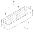
- FIG. 1 is a perspective view showing a storage container according to the first embodiment of the present invention.
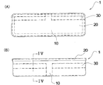
- FIG. 2 is an exploded perspective view showing the storage container of FIG. 3A is a plan view of the storage container of FIG. 1 viewed in the direction of arrow IIIA
- FIG. 3B is a front view of the storage container of FIG. 1 viewed in the direction of arrow IIIB.
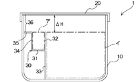
- FIG. 4 is a cross-sectional view of the storage container of FIG. 3B taken along the alternate long and short dash line IV-IV in the direction of the arrow.
- 5A to 5D are cross-sectional views for explaining an example of use of the storage container of FIG.
- FIG. 6 is an explanatory diagram for explaining an example of use of the storage container.
- FIG. 1 is a perspective view showing a storage container according to the first embodiment of the present invention.
- FIG. 2 is an exploded perspective view showing the storage container of FIG. 3A is a plan view of the storage container of FIG. 1 viewed in the direction of arrow III
- FIG. 7 is a perspective view showing a storage container according to the second embodiment of the present invention.
- 8 is a cross-sectional view showing the storage container of FIG. 9 is an exploded perspective view showing the measuring member of the storage container of FIG.
- FIG. 10 is a perspective view showing a storage container according to the third embodiment of the present invention.
- FIG. 11 is an exploded perspective view showing the storage container of FIG.
- FIG. 12 is a perspective view showing a storage container according to the fourth embodiment of the present invention.
- FIG. 15 is a side view of the storage container of FIG. 13 as viewed in the direction of arrow XV.
- FIG. 16 is a perspective view showing a storage container according to the fifth embodiment of the present invention.
- 17 is a plan view showing the storage container of FIG.
- FIG. 1 is a perspective view showing a storage container 1 according to the first embodiment of the present invention.
- the broken lines in the figure indicate the outline, ridge line, and valley line of each member that can be seen through the transparent member (the same applies to FIGS. 2, 3, 7, and 9 to 17).
- FIG. 2 is an exploded perspective view showing the storage container 1 of FIG. 3A is a plan view of the storage container 1 of FIG. 1 as viewed in the direction of arrow IIIA
- FIG. 3B is a front view of the storage container 1 of FIG. 1 as viewed in the direction of arrow IIIB.
- the storage container 1 has a long and thin box shape as a whole, and has a substantially rectangular parallelepiped container body 10 having an opening at the top, and a lid 20 that can seal the opening of the container body 10.
- the storage container 1 is suitable for storing stick-shaped dry noodles (spaghetti, udon, soba, ramen, etc.) cut to a certain length.
- the container body 10 is made of a synthetic resin such as polypropylene.
- the lid 20 is made of a synthetic resin such as polyethylene or silicone rubber, and has a certain flexibility. In a preferred example, the lid 20 is made of a material that is more flexible than the container body 10. To attach the lid 20, the edge of the lid 20 is fitted to the outside of the upper edge of the container body 10.
- the lid 20 may have a groove on the periphery, and the groove may be fitted to the upper edge of the container body 10.
- the container body 10 and the lid 20 are both transparent, either one of the container body 10 and the lid 20 is transparent, or both the container body 10 and the lid 20 are partly transparent, It is assumed that the state of the internal rod-shaped dry noodles, in particular, the state of measurement of the rod-shaped dry noodles described later can be confirmed from the outside.
- FIG. 4 is a cross-sectional view of the storage container of FIG. 3B taken along the alternate long and short dash line IV-IV in the direction of the arrow.
- the measuring member 30 shown in the figure has a plate-like bottom portion 31 substantially parallel to the bottom surface of the container body 10 and a first wall portion 32 erected in a wall shape upward from an edge on one longitudinal side of the bottom portion 31.
- a wall-like skirt portion 33 extending downward from the same edge of the bottom portion 31 to the bottom surface of the container body 10 and fixed to the bottom surface, and a wall shape upward from the other longitudinal side edge of the bottom portion 31.
- a second wall portion 34 erected on the wall, and extends from the upper edge of the second wall portion 34 to the wall of the container body 10 substantially in parallel to the bottom surface of the container body 10 and is fixed or in contact with the wall.
- a plate-like step 35 As a method of fixing the skirt portion 33 or the stepped portion 35 to the inner surface of the container body 10, any method such as adhesion or fusion can be used.
- the measuring member 30 in the illustrated example is drawn as a transparent member, the measuring member 30 may be opaque. In this case, the measuring member 30 may be made of metal, wood, etc. in addition to those made of synthetic resin.
- the upper portion is open across the longitudinal direction between the first wall portion 32 and the second wall portion 34 of the measuring member 30.
- the two measuring members 30 are arranged in series in the longitudinal direction in the container body 10, and a gap (such as a human finger can be smoothly inserted between the measuring members 30 ( A gap of about 2 to 3 centimeters) is left open.
- the first wall portion 32 and the second wall portion 34 have the same height.
- the first wall portion 32 corresponds to the “first side portion” of the present invention, and the second wall portion 34, the step portion 35, and the portion of the wall of the container body from the portion where the step portion 35 is fixed or in contact with the lid 20.
- the portion up to (the wall portion 36) corresponds to the “second side portion” of the present invention, and the second side portion is higher than the first side portion. Due to the difference in height, in the state where the lid 20 is attached to the container main body 10, the height direction is between the first wall portion 32 (first side portion) and the lid 20 as shown in FIG. 4. There is a predetermined gap ⁇ H.
- the bottom part 31, the first wall part 32, the second wall part 34, the step part 35, and the wall part 36 correspond to the “metering part” of the present invention.
- a region region indicated by a one-dot chain line a
- first wall 32, and second wall 34 is defined as a “metering region”
- the metering region is filled.
- the amount of the rod-shaped dry noodles put in the container is a target amount to be measured in the storage container 1.
- FIG. 5 (A) shows a state in which stick-shaped dry noodles 40 such as spaghetti are stored inside the container body 10.
- the rod-shaped dry noodle 40 is a space defined by the bottom surface of the container body 10, the wall, the skirt portion 33, and the first wall portion 32 (indicated by a dashed line in FIG. 4). Area (hereinafter referred to as “accommodating portion”).
- the length in the longitudinal direction of the storage container 1 is set to be somewhat longer than the length of the rod-shaped dry noodle 40 to be accommodated.
- the entire storage container 1 is tilted toward the measuring section while keeping the longitudinal axis of the storage container 1 close to horizontal, so that the storage section At least a part of the rod-shaped dry noodles 40 stored in the container is caused to flow toward the measuring section.
- more rod-shaped dry noodles 40 than the amount that fills the measurement area A are caused to flow from the housing part over the first wall part 32 to the measurement part side.
- the rod-shaped dry noodle 40 that has flowed into the measuring section side not only fills the measuring area a, but also includes the wall portion 36 of the container body 10 that forms the measuring section and the portion of the lid 20 that is in contact therewith. It also flows into the corners.
- the entire storage container 1 is tilted in the direction opposite to the inclination of FIG. 5B while keeping the longitudinal axis of the storage container 1 near horizontal. More specifically, as shown in FIG. 5 (B), the entire storage container 1 is temporarily returned to a horizontal position while keeping the longitudinal axis of the storage container 1 near horizontal from the state in which the measuring portion is at the bottom. Further, the entire storage container 1 is tilted toward the housing portion. As a result, as shown in FIG. 5C, a part of the rod-shaped dry noodle 40 that has flowed into the weighing unit side is spilled back from the weighing unit side over the first wall portion 32 to the housing unit. .
- FIG. 5D shows a state in which the rod-shaped dry noodle 40 is worn back and returned to the initial posture. Thereby, the stick-shaped dry noodle 40 of the quantity which fills the measurement area
- the rod-shaped dry noodles 40 weighed in this way can be easily scooped up by opening the lid 20 and putting a finger in the gap between the two weighing members 30.
- the storage container 1 of the present embodiment uses the behavior in which the rod-shaped dry noodles 40 stored in the storage container 1 move so as to flow in a direction perpendicular to the longitudinal direction of the storage container 1.
- a simple structure it is possible to easily measure the required amount of the rod-shaped dry noodle 40 without touching the rod-shaped dry noodle 40 directly.
- the weighed bar-shaped dry noodles 40 are combined into one bundle without causing strong friction between the edge of the take-out opening and the other bar-shaped dry noodles 40, the weighed bar-shaped dry noodles 40 It can be easily taken out.
- the lid 20 may be attached to the container body 10 by a hinge structure.
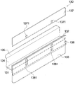
- FIG. 7 is a perspective view showing a storage container 101 according to the second embodiment.
- the storage container 101 of the present embodiment is different from the measurement member 30 of the storage container 1 of the first embodiment in the shape of the measurement member 130.
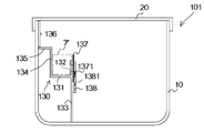
- FIG. 8 is a cross-sectional view of the storage container 101 of FIG. 7, which replaces FIG. 4 of the first embodiment.
- the cross section shown in FIG. 8 is a cross section passing through one convex portion 1371 described later.
- FIG. 9 is an exploded perspective view showing the measuring member 130 of the present embodiment.
- each measuring member 130 of the present embodiment includes a plate-like bottom portion 131 substantially parallel to the bottom surface of the container body 10, and an upper edge from one longitudinal side edge of the bottom portion 131.
- a first wall portion 132 standing in a wall shape in the direction, a wall-like skirt portion 133 extending downward from the same edge of the bottom portion 131 to the bottom surface of the container body 10 and fixed to the bottom surface;
- a second wall portion 134 standing in a wall shape upward from the other longitudinal side edge of the bottom portion 131, and an upper end portion of the second wall portion 134 from the upper end portion of the container body 10 to be substantially parallel to the bottom surface of the container body 10.
- a plate-like step portion 135 that extends to the wall and adheres to or contacts the wall.
- the weighing member 130 further includes a movable weir 137 that is overlapped with the surface of the first wall portion 132 on the housing portion side and is movable in the vertical direction. Further, a pressing plate 138 extending in parallel with the first wall portion 132 is provided upward from the surface on the accommodating portion side of the skirt portion 133, and a predetermined gap is provided between the first wall portion 132 and the pressing plate 138. The movable weir 137 can be inserted into the gap.
- the presser plate 138 is provided with two oblong holes 1381 extending in the vertical direction at a predetermined interval in the longitudinal direction of the presser plate 138, and the movable weir 137 corresponds to the position of the oval hole 1381.
- Two convex portions 1371 are provided at two locations.
- the movable weir 137 is inserted into the gap between the first wall portion 132 and the pressing plate 138, and the two convex portions 1371 of the movable weir 137 are accommodated in the two oblong holes 1381 of the pressing plate 138, respectively.
- the user moves the two protrusions 1371 of the movable weir 137 up and down within the two oblong holes 1381 of the holding plate 138, thereby moving the movable weir 137 to the first. It is possible to move up and down with respect to the wall portion 132. Thus, the height of the movable weir 137 can be adjusted.
- the first wall portion 132 is lower than the second wall portion 134.
- the position of the upper end of the movable weir 137 is adjusted from a position lower than the second wall portion 134 to a position having the same height as the second wall portion 134. Can do.
- the region defined by the bottom 131, the second wall 134, the movable weir 137, and the second wall 134 and does not exceed the height of the movable weir 137 corresponds to the weighing area a. Therefore, by adjusting the height of the movable weir 137, the size of the measuring area can be adjusted, and the amount of the bar-shaped dry noodles 40 that can be measured by the method of FIG. 5 can be adjusted. You may make it easy to understand the adjustment amount of the rod-shaped dry noodles 40 to which the movable weir 137 is calibrated and measure it, or may make it easy to fix the position of the movable weir 137 by a latch mechanism.
- a combination of the first wall portion 132 and the movable weir 137 corresponds to the “first side portion” of the present invention, and the second wall portion 134, the step portion 135, and the step portion 135 among the walls of the container body are included.
- a portion from the portion that is fixed or in contact to the lid 20 corresponds to the “second side portion” of the present invention.
- the bottom 131, the first wall 132, the second wall 134, the step 135, the wall portion 136, and the movable weir 137 constitute the “metering unit” of the present invention.
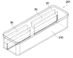
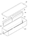
- FIG. 10 is a perspective view showing a storage container 201 of the third embodiment
- FIG. 11 is an exploded perspective view.
- the shape of the weighing member 30 of the storage container 201 of this embodiment is the same as that of the weighing member 30 of the first embodiment.
- the metering member 30 of the present embodiment is not permanently fixed to the container body 10 with an adhesive or the like, but to the groove 211 extending on the bottom surface of the container body 210 and a part of the wall.
- the container body 10 is fixed by inserting the skirt portion 33 of the measuring member 30.
- the measuring member 30 can be used for measuring the rod-shaped dry noodle 40 as described with reference to FIG. 5. If the measuring member 30 is removed, the amount of the rod-shaped dry noodle 40 that can be accommodated in the container body 1. The usage can be changed as needed, such as increasing the number.
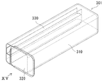
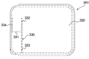
- FIG. 12 is a perspective view showing a storage container 301 according to the fourth embodiment of the present invention
- FIG. 14 is a side view of the storage container 301 of FIG. 12 as viewed in the direction of arrow XIV.
- the container body 310 of the storage container 301 of the present embodiment has an opening on one end side in the longitudinal direction instead of having an opening in the upper part.
- the lid 320 is slidably contacted with the upper and lower edge portions of the opening of the container main body 310 and slides in the horizontal direction, so that the opening of the container main body 310 can be opened and closed.
- FIG. 13 is a perspective view showing an example of use of the storage container of FIG. 12, showing a state in which the lid 320 is partially opened.
- FIG. 15 is a side view of the storage container of FIG. 13 as viewed in the direction of arrow XV.
- the bar-shaped dry noodle 40 was weighed by the same method as the method for measuring the bar-shaped dry noodle 40 by the storage container 1 according to the first embodiment described with reference to FIG. After the state is reached, the lid 320 is opened to such an extent that the weighing area is opened and the accommodating portion is not opened as shown in FIG. If the storage container 301 is tilted toward the opening in this state, the weighed stick-shaped dry noodles 40 can be easily taken out.
- the upper part of the measuring area A is open, and the area of the open portion of the opening of the container body 10 is larger than the apparent sectional area of the weighed rod-shaped dry noodle 40 (that is, the area of the measuring area A), and
- the weighed rod-shaped dry noodle 40 is separated from the bottom 331, the wall portions 332, 334 of the weighing member 330, There is no strong friction with other rod-shaped dry noodles 40.
- the weighed stick-shaped dry noodles 40 can be smoothly taken out without being caught by the edge of the opening or other stick-shaped dry noodles 40.
- the measuring member 330 of this embodiment is not divided into a plurality of parts in the longitudinal direction as shown in FIGS. 12 to 15, the measuring member 330 has a bottom portion 331, a first wall portion 332, a skirt portion 333, and a second wall portion 334, and corresponds to the step portion 35 of the first embodiment.
- the second wall portion 334 directly adheres to or contacts the wall of the container body 310.
- the wall portion 336 constituting the “second side portion” can be a wall portion between the upper end of the second wall portion 334 and the illustrated top surface of the container body 10. .
- the second wall portion 334 may be eliminated, and the bottom portion 331 may be directly fixed or in contact with the wall.
- the wall portion 336 can be a portion of the wall between the fixed portion or the contact portion with the bottom portion 331 and the illustrated top surface of the container body 10.
- the lid 320 is not limited to the one that opens and closes by sliding, but may be one that opens and closes the entire opening of the container body 310 by a hinge structure, or that opens and closes the opening except for the accommodating portion.
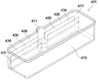
- FIG. 16 is a perspective view showing a storage container 401 according to this embodiment
- FIG. 17 is a plan view showing the storage container 401 of FIG.
- the storage container 401 of the present embodiment eliminates the step portion 35 of the storage container 1 of the first embodiment so that the second wall portion 434 of the measuring member 430 is directly fixed or in contact with the wall of the container body 410, A portion of the wall of the container body 410 proximate to the gap between the measuring members 430 is bulged outward to form a bulging portion 411.
- the lid 420 also has a shape corresponding to the bulge.
- the wall portion 436 constituting the “second side portion” can be a wall portion between the upper end of the second wall portion 434 and the lid 420. Further, the second wall portion 434 may be eliminated, and the bottom portion 431 may be fixed or in contact with the wall directly.
- the wall portion 436 in this case can be a portion of the wall between the lid 420 and the contact with the bottom portion 431 or the contact portion.
- the measuring member may be divided into three or more instead of two. Moreover, as long as the function demonstrated in this specification can be exhibited, the measuring member may be further subdivided, or a plurality of comb-like members arranged in the longitudinal direction of the storage container may be assembled.
- the second embodiment by adjusting the height of the movable weir 137, the size of the weighing area a is adjusted, and the amount of the rod-shaped dry noodle 40 that can be measured by the method of FIG. 5 is adjusted, but instead, By adjusting the height of the bottoms 31, 131, 331, 431, the size of the measuring area a may be adjusted, and the amount of the rod-shaped dry noodles 40 that can be measured by the method of FIG. 5 may be adjusted.
- the height of the bottom portions 31, 131, 331, 431 may be adjusted by installing a raised bottom plate on the inner bottom surface of the bottom portions 31, 131, 331, 431.
Landscapes
- Engineering & Computer Science (AREA)
- Mechanical Engineering (AREA)
- Food Science & Technology (AREA)
- Physics & Mathematics (AREA)
- Fluid Mechanics (AREA)
- General Physics & Mathematics (AREA)
- Details Of Rigid Or Semi-Rigid Containers (AREA)
- Devices For Warming Or Keeping Food Or Tableware Hot (AREA)
- Closures For Containers (AREA)
Applications Claiming Priority (2)
| Application Number | Priority Date | Filing Date | Title |
|---|---|---|---|
| JP2016147799A JP6894090B2 (ja) | 2016-07-27 | 2016-07-27 | 計量機能付き棒状乾麺保存容器 |
| JP2016-147799 | 2016-07-27 |
Publications (1)
| Publication Number | Publication Date |
|---|---|
| WO2018021147A1 true WO2018021147A1 (ja) | 2018-02-01 |
Family
ID=61017310
Family Applications (1)
| Application Number | Title | Priority Date | Filing Date |
|---|---|---|---|
| PCT/JP2017/026322 Ceased WO2018021147A1 (ja) | 2016-07-27 | 2017-07-20 | 計量機能付き棒状乾麺保存容器 |
Country Status (2)
| Country | Link |
|---|---|
| JP (1) | JP6894090B2 (cg-RX-API-DMAC10.html) |
| WO (1) | WO2018021147A1 (cg-RX-API-DMAC10.html) |
Cited By (1)
| Publication number | Priority date | Publication date | Assignee | Title |
|---|---|---|---|---|
| CN113335768A (zh) * | 2021-06-15 | 2021-09-03 | 海南圣岛科技有限公司 | 一种方便取药的储药瓶 |
Citations (8)
| Publication number | Priority date | Publication date | Assignee | Title |
|---|---|---|---|---|
| JPS492260A (cg-RX-API-DMAC10.html) * | 1972-04-24 | 1974-01-10 | ||
| JPS5487984U (cg-RX-API-DMAC10.html) * | 1977-11-29 | 1979-06-21 | ||
| JPH08292085A (ja) * | 1995-04-20 | 1996-11-05 | The Ikeda:Kk | 麺計量機 |
| JP2006105726A (ja) * | 2004-10-04 | 2006-04-20 | Oizumi Bussan Tokyo:Kk | 乾麺類の計量器 |
| JP2009208814A (ja) * | 2008-03-04 | 2009-09-17 | Shoichi Izeki | 乾麺計量機能付き容器 |
| JP3179053U (ja) * | 2012-08-02 | 2012-10-11 | 孝治 村岡 | 乾麺等の計量具 |
| JP2013128446A (ja) * | 2011-12-21 | 2013-07-04 | Nisshin Seifun Group Inc | 乾麺用計量器および乾麺収納容器 |
| WO2014174130A1 (es) * | 2013-04-24 | 2014-10-30 | Serrano González Antonio | Dispensador medidor de alimentos |
Family Cites Families (5)
| Publication number | Priority date | Publication date | Assignee | Title |
|---|---|---|---|---|
| JPS53125567U (cg-RX-API-DMAC10.html) * | 1977-03-15 | 1978-10-05 | ||
| JPS55100123U (cg-RX-API-DMAC10.html) * | 1979-01-01 | 1980-07-12 | ||
| JPH07309378A (ja) * | 1994-05-15 | 1995-11-28 | Toooshiyou Rojitetsuku Kk | 計量小出し枡構造とこれを用いた計量小出し栓および計量小出し容器 |
| JP2003237858A (ja) * | 2002-02-12 | 2003-08-27 | Kaijirushi Hamono Kaihatsu Center:Kk | 流動物又は小さな固体の集合物から成る食材の保存用容器 |
| JP4231750B2 (ja) * | 2003-08-05 | 2009-03-04 | アテナ工業株式会社 | 計量機能を有する容器 |
-
2016
- 2016-07-27 JP JP2016147799A patent/JP6894090B2/ja active Active
-
2017
- 2017-07-20 WO PCT/JP2017/026322 patent/WO2018021147A1/ja not_active Ceased
Patent Citations (8)
| Publication number | Priority date | Publication date | Assignee | Title |
|---|---|---|---|---|
| JPS492260A (cg-RX-API-DMAC10.html) * | 1972-04-24 | 1974-01-10 | ||
| JPS5487984U (cg-RX-API-DMAC10.html) * | 1977-11-29 | 1979-06-21 | ||
| JPH08292085A (ja) * | 1995-04-20 | 1996-11-05 | The Ikeda:Kk | 麺計量機 |
| JP2006105726A (ja) * | 2004-10-04 | 2006-04-20 | Oizumi Bussan Tokyo:Kk | 乾麺類の計量器 |
| JP2009208814A (ja) * | 2008-03-04 | 2009-09-17 | Shoichi Izeki | 乾麺計量機能付き容器 |
| JP2013128446A (ja) * | 2011-12-21 | 2013-07-04 | Nisshin Seifun Group Inc | 乾麺用計量器および乾麺収納容器 |
| JP3179053U (ja) * | 2012-08-02 | 2012-10-11 | 孝治 村岡 | 乾麺等の計量具 |
| WO2014174130A1 (es) * | 2013-04-24 | 2014-10-30 | Serrano González Antonio | Dispensador medidor de alimentos |
Cited By (2)
| Publication number | Priority date | Publication date | Assignee | Title |
|---|---|---|---|---|
| CN113335768A (zh) * | 2021-06-15 | 2021-09-03 | 海南圣岛科技有限公司 | 一种方便取药的储药瓶 |
| CN113335768B (zh) * | 2021-06-15 | 2022-08-19 | 石家庄市雪芝莲文化传媒有限公司 | 一种方便取药的储药瓶 |
Also Published As
| Publication number | Publication date |
|---|---|
| JP2018016352A (ja) | 2018-02-01 |
| JP6894090B2 (ja) | 2021-06-23 |
Similar Documents
| Publication | Publication Date | Title |
|---|---|---|
| US2917162A (en) | Pill dispensing unit | |
| EP2526029B1 (en) | Test strip container with strip retainer and methods of manufacturing and utilization thereof | |
| JP2018016352A (ja) | 計量機能付き棒状乾麺保存容器 | |
| JP7266280B2 (ja) | 計量キャップ | |
| US20140033658A1 (en) | Dry goods portion control container | |
| US4334361A (en) | Pasta gauge | |
| KR200386849Y1 (ko) | 계량 스푼 수납구를 갖는 용기 캡 | |
| US3511416A (en) | Metering spout | |
| JP6745618B2 (ja) | 計量カップ | |
| US20100270331A1 (en) | Spice container with pivoting cover | |
| US3456852A (en) | Measuring arrangement | |
| KR101523932B1 (ko) | 양념통 | |
| WO2017151739A1 (en) | Container | |
| WO2001023297A1 (en) | Adjustable measuring pour spout | |
| JP2003237858A (ja) | 流動物又は小さな固体の集合物から成る食材の保存用容器 | |
| JP6950995B1 (ja) | 計量収納容器 | |
| JPH0948452A (ja) | 粉粒体の計量方法及び粉粒体計量容器 | |
| JP2003232665A (ja) | 計量スプーン | |
| US2740524A (en) | Measuring sifters | |
| KR200477427Y1 (ko) | 내용물의 인출이 용이한 수납용기 | |
| ITMI930372A1 (it) | Contenitore con dosatore incorporato | |
| JPH08207972A (ja) | 定量容器 | |
| JP2005001705A (ja) | 計量容器 | |
| KR20250138125A (ko) | 화장품용 팩키징 | |
| HK1238323A1 (en) | A measuring cup |
Legal Events
| Date | Code | Title | Description |
|---|---|---|---|
| 121 | Ep: the epo has been informed by wipo that ep was designated in this application |
Ref document number: 17834155 Country of ref document: EP Kind code of ref document: A1 |
|
| NENP | Non-entry into the national phase |
Ref country code: DE |
|
| 122 | Ep: pct application non-entry in european phase |
Ref document number: 17834155 Country of ref document: EP Kind code of ref document: A1 |