WO2018012471A1 - Dispositif de commande d'alimentation électrique et système d'alimentation électrique - Google Patents
Dispositif de commande d'alimentation électrique et système d'alimentation électrique Download PDFInfo
- Publication number
- WO2018012471A1 WO2018012471A1 PCT/JP2017/025181 JP2017025181W WO2018012471A1 WO 2018012471 A1 WO2018012471 A1 WO 2018012471A1 JP 2017025181 W JP2017025181 W JP 2017025181W WO 2018012471 A1 WO2018012471 A1 WO 2018012471A1
- Authority
- WO
- WIPO (PCT)
- Prior art keywords
- state
- switch
- resistance
- switching
- resistance value
- Prior art date
Links
Images


Classifications
-
- F—MECHANICAL ENGINEERING; LIGHTING; HEATING; WEAPONS; BLASTING
- F02—COMBUSTION ENGINES; HOT-GAS OR COMBUSTION-PRODUCT ENGINE PLANTS
- F02N—STARTING OF COMBUSTION ENGINES; STARTING AIDS FOR SUCH ENGINES, NOT OTHERWISE PROVIDED FOR
- F02N11/00—Starting of engines by means of electric motors
- F02N11/08—Circuits or control means specially adapted for starting of engines
-
- H—ELECTRICITY
- H01—ELECTRIC ELEMENTS
- H01M—PROCESSES OR MEANS, e.g. BATTERIES, FOR THE DIRECT CONVERSION OF CHEMICAL ENERGY INTO ELECTRICAL ENERGY
- H01M10/00—Secondary cells; Manufacture thereof
- H01M10/42—Methods or arrangements for servicing or maintenance of secondary cells or secondary half-cells
- H01M10/44—Methods for charging or discharging
-
- H—ELECTRICITY
- H01—ELECTRIC ELEMENTS
- H01M—PROCESSES OR MEANS, e.g. BATTERIES, FOR THE DIRECT CONVERSION OF CHEMICAL ENERGY INTO ELECTRICAL ENERGY
- H01M10/00—Secondary cells; Manufacture thereof
- H01M10/42—Methods or arrangements for servicing or maintenance of secondary cells or secondary half-cells
- H01M10/48—Accumulators combined with arrangements for measuring, testing or indicating the condition of cells, e.g. the level or density of the electrolyte
- H01M10/482—Accumulators combined with arrangements for measuring, testing or indicating the condition of cells, e.g. the level or density of the electrolyte for several batteries or cells simultaneously or sequentially
-
- H—ELECTRICITY
- H02—GENERATION; CONVERSION OR DISTRIBUTION OF ELECTRIC POWER
- H02J—CIRCUIT ARRANGEMENTS OR SYSTEMS FOR SUPPLYING OR DISTRIBUTING ELECTRIC POWER; SYSTEMS FOR STORING ELECTRIC ENERGY
- H02J7/00—Circuit arrangements for charging or depolarising batteries or for supplying loads from batteries
- H02J7/0013—Circuit arrangements for charging or depolarising batteries or for supplying loads from batteries acting upon several batteries simultaneously or sequentially
- H02J7/0014—Circuits for equalisation of charge between batteries
- H02J7/0016—Circuits for equalisation of charge between batteries using shunting, discharge or bypass circuits
-
- B—PERFORMING OPERATIONS; TRANSPORTING
- B60—VEHICLES IN GENERAL
- B60L—PROPULSION OF ELECTRICALLY-PROPELLED VEHICLES; SUPPLYING ELECTRIC POWER FOR AUXILIARY EQUIPMENT OF ELECTRICALLY-PROPELLED VEHICLES; ELECTRODYNAMIC BRAKE SYSTEMS FOR VEHICLES IN GENERAL; MAGNETIC SUSPENSION OR LEVITATION FOR VEHICLES; MONITORING OPERATING VARIABLES OF ELECTRICALLY-PROPELLED VEHICLES; ELECTRIC SAFETY DEVICES FOR ELECTRICALLY-PROPELLED VEHICLES
- B60L2240/00—Control parameters of input or output; Target parameters
- B60L2240/40—Drive Train control parameters
- B60L2240/54—Drive Train control parameters related to batteries
- B60L2240/545—Temperature
-
- H—ELECTRICITY
- H01—ELECTRIC ELEMENTS
- H01M—PROCESSES OR MEANS, e.g. BATTERIES, FOR THE DIRECT CONVERSION OF CHEMICAL ENERGY INTO ELECTRICAL ENERGY
- H01M10/00—Secondary cells; Manufacture thereof
- H01M10/42—Methods or arrangements for servicing or maintenance of secondary cells or secondary half-cells
- H01M10/425—Structural combination with electronic components, e.g. electronic circuits integrated to the outside of the casing
- H01M2010/4271—Battery management systems including electronic circuits, e.g. control of current or voltage to keep battery in healthy state, cell balancing
Definitions
- the present disclosure relates to a power supply control device applied to a power supply system including a plurality of power storage means and a power supply system.
- connection switching means such as a relay and a switch are provided on each energization path leading to the plurality of storage batteries.
- the difference in the number of relays and switches on the energization path in the series / parallel state causes a difference in the resistance value of the energization path in each storage battery. Therefore, a difference arises in the charging / discharging current which flows through a some storage battery, and dispersion
- SOC electrical residual capacity
- the present disclosure has been made in view of the above problems, and its main purpose is to suppress the occurrence of excessive current in a system having a plurality of power storage means that can be switched in series and parallel, and as a result, power storage means, switches, etc. It is an object of the present invention to provide a power supply control device and a power supply system capable of protecting the above.
- the power supply control device of the present disclosure includes a plurality of power storage means and a plurality of switch means provided in an electrical path leading to each power storage means, and the plurality of power storage means connected in parallel to each other and connected in series to each other Applied to a power supply system including a switching unit that switches between the connected serial states.
- the power supply control device has a correlation with the magnitude of the current flowing through the energization path including the path between the power storage units in the parallel state or the series state as a parameter indicating the state of the plurality of switch units.
- An acquisition unit that acquires a switch state parameter; and a resistance control unit that adjusts a resistance value of a resistance variable unit existing in the energization path in the parallel state or the series state based on the switch state parameter. .
- a power supply system that includes a plurality of power storage means and enables switching between parallel connection and series connection of each power storage means by turning on and off the plurality of switch means, due to SOC (remaining electric capacity) in each power storage means For example, there is a concern that overcurrent due to capacity self-adjustment flows between the respective power storage means.
- SOC main electric capacity
- a correlation is given to the magnitude of the current flowing through the energization path including the path between the power storage means in the parallel state or the series state.
- the switch state parameter is acquired, and the resistance value of the resistance variable unit existing in the energization path in the parallel state or series state is adjusted based on the switch state parameter.
- the resistance value of the resistance variable unit it is possible to control the current flowing through the energization path in a parallel state or a series state, that is, the current flowing between the power storage units, and even if there is a variation in SOC between the power storage units, It is possible to suppress an overcurrent from flowing through the switching means for series / parallel switching. As a result, proper use of each power storage means can be realized while protecting the power storage means and the switch.
- a configuration in which a plurality of power storage units may be any configuration having two or more power storage units that can be switched in series-parallel, for example, three or more power storage units.
- a configuration in which series-parallel switching is performed for at least two of the power storage units is also included.
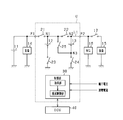
- FIG. 1 is an electric circuit diagram showing the power supply system in the first embodiment.
- FIG. 2 is a diagram showing a specific configuration of the switch.
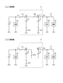
- 3A is a diagram showing a state in which lithium ion storage batteries are connected in parallel
- FIG. 3B is a diagram showing a state in which lithium ion storage batteries are connected in series
- 4A is a diagram showing a current flow during parallel charging
- FIG. 4B is a diagram showing a current flow during parallel discharging
- FIG. 5 is a diagram showing the flow of current during series discharge
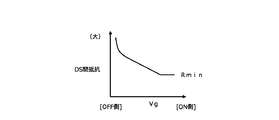
- FIG. 6 is a diagram showing the relationship between the gate voltage and the drain-source resistance.
- FIG. 7 is a flowchart showing a processing procedure for controlling the connection state and charge / discharge current of the lithium ion storage battery
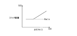
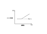
- FIG. 8 is a diagram showing the relationship between the terminal voltage difference ⁇ V and the switch resistance value.
- FIG. 9 is a diagram showing the relationship between the switch temperature and the switch resistance value.
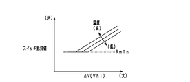
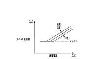
- FIG. 10 is a diagram showing the relationship among the terminal voltage difference ⁇ V, the switch temperature, and the switch resistance value.
- FIG. 11 is a time chart for more specifically explaining resistance value control associated with series-parallel switching of a lithium ion storage battery
- FIG. 12 is a time chart showing a change in energization current when switching a lithium ion storage battery from a serial state to a parallel state;
- FIG. 13 is a diagram illustrating a relationship between the energization current and the switch resistance value.
- FIG. 14 is a diagram illustrating a relationship among energization current, switch temperature, and switch resistance value.
- an in-vehicle power supply device that supplies electric power to various devices of the vehicle in a vehicle that runs using an engine (internal combustion engine) as a drive source is embodied.
- the power supply system is a so-called dual power supply system including a first power storage device having a lead storage battery and a second power storage device having a plurality of lithium ion storage batteries as the power storage device. .
- the power supply system includes a lead storage battery 11 and two lithium ion storage batteries 12 and 13, and from each storage battery 11 to 13 to various electric loads 14 and 15 and a rotating electrical machine 16. Can be fed. Further, each of the storage batteries 11 to 13 can be charged by the rotating electrical machine 16.
- the lead storage battery 11 is a well-known general-purpose storage battery.
- the lithium ion storage batteries 12 and 13 are high-density storage batteries that have less power loss in charge and discharge and higher output density and energy density than the lead storage battery 11.
- the lithium ion storage batteries 12 and 13 may be storage batteries having higher energy efficiency during charging / discharging than the lead storage battery 11.
- the lithium ion storage batteries 12 and 13 are each configured as an assembled battery having a plurality of single cells.
- the rated voltages of the storage batteries 11 to 13 are the same, for example, 12V.
- the two lithium ion storage batteries 12 and 13 are housed in a housing case and configured as an integral battery unit U.
- the battery unit U has two output terminals P1 and P2, among which the lead storage battery 11 and the electric load 14 are connected to the output terminal P1, and the electric load 15 and the rotating electrical machine 16 are connected to the output terminal P2. Has been.
- the electrical load 14 connected to the output terminal P1 is a 12V system load driven based on 12V power supply from the lead storage battery 11 or the lithium ion storage batteries 12 and 13.
- the electric load 14 includes a constant voltage request load that is required to be constant or at least stable so that the voltage of the supplied power fluctuates within a predetermined range, and a general electric load other than the constant voltage request load. It is.
- the constant voltage required load is a load to be protected and is a load in which power supply failure is not allowed. Specific examples of the constant voltage required load include various ECUs such as a navigation device, an audio device, a meter device, and an engine ECU.
- the electric load 15 is a high-voltage load in which a large driving force is temporarily required, for example, when the vehicle is traveling, that is, a high power requirement may occur.
- a specific example is an electric steering device.
- the electric load 14 connected to the output terminal P1 corresponds to a low voltage electric load
- the electric load 15 and the rotating electrical machine 16 connected to the output terminal P2 correspond to a high voltage electric load.
- the rotating shaft of the rotating electrical machine 16 is drivingly connected to an engine output shaft (not shown) by a belt or the like.
- the rotating shaft of the rotating electrical machine 16 is rotated by the rotation of the engine output shaft, while the rotating shaft of the rotating electrical machine 16 is rotated.
- the rotating electrical machine 16 is an MG (Motor Generator), and has a power generation function for generating power (regenerative power generation) by rotation of the engine output shaft and the axle, and a power running function for applying rotational force to the engine output shaft.
- the rotating electrical machine 16 is configured to perform adjustment of the generated current during power generation and torque adjustment during powering driving by an inverter as a power conversion device provided integrally or separately.
- the engine is started and torque assist is performed by driving the rotating electrical machine 16.
- the rotating electrical machine 16 is an electric load in terms of adding power to the engine output shaft, and is a high power / high current load in comparison with the electric load 14.
- a switch 17 is provided between the electric load 15 and the rotating electrical machine 16, and the storage batteries 11 to 13 and the rotating electrical machine 16 and the electrical load 15 are electrically connected or disconnected by turning on or off the switch 17. It is like that.
- the two lithium ion storage batteries 12 and 13 can be switched between a parallel connection state and a serial connection state, which will be described in detail.
- switches 21 and 22 are provided in series on the electric path L1 between the output terminals P1 and P2.
- the electrical path L1 is also a part of the energization path where the electrical loads 14 and 15 and the rotating electrical machine 16 are connected to the lead storage battery 11 in the present system.
- the positive terminal (positive terminal) of the lithium ion storage battery 12 is connected to the first point N1 between the switches 21 and 22, and the positive terminal of the lithium ion storage battery 13 is connected to the second point N2 between the switch 22 and the output terminal P2. It is connected.
- switches 23 and 24 are provided between the negative terminals of the lithium ion storage batteries 12 and 13 and the ground, respectively.
- the first point N1 is connected to a third point N3 between the negative terminal of the lithium ion storage battery 13 and the switch 24, and a switch 25 is provided in the connection path.
- the switches 21 to 25 correspond to “switching units”.
- Each of the switches 21 to 25 is composed of a semiconductor switching element such as a MOSFET, IGBT, or bipolar transistor.
- each of the switches 21 to 25 is configured by a MOSFET, and the switches 21 to 25 are turned on and off according to application of a predetermined gate voltage.
- each of the switches 21 to 25 is configured to have two sets of MOSFETs, and the parasitic diodes of each set of MOSFETs are connected in series so that they are opposite to each other. Good.
- the parasitic diodes that are opposite to each other completely cut off the current that flows through the path in which the switches 21 to 25 are turned off.
- the configuration using semiconductor switching elements in each of the switches 21 to 25 may be arbitrary. For example, a configuration in which parasitic diodes of MOSFETs are not arranged in opposite directions may be used.
- FIG. 3A shows a state in which the lithium ion storage batteries 12 and 13 are connected in parallel
- FIG. 3B shows a state in which the lithium ion storage batteries 12 and 13 are connected in series.
- the energization path shown in FIG. 3A is a “parallel energization path”
- the energization path shown in FIG. 3B is a “series energization path”.
- the switch 17 is turned off in the parallel state and turned on as necessary in the series state.
- the switches 21 to 24 are turned on and the switch 25 is turned off.
- the lithium ion storage batteries 12 and 13 are in a parallel relationship.
- the output voltages of the output terminals P1 and P2 are both approximately 12V.
- the lead storage battery 11 and the lithium ion storage batteries 12 and 13 are connected in parallel to the electric load 14 on the P1 side, and the lead storage battery 11 and the lithium ion storage battery are connected in parallel to the rotating electrical machine 16 on the P2 side. 12 and 13 are connected.
- the electrical load 14 is connected to an intermediate position (first point N1) on the path connecting the positive electrodes of the lithium ion storage batteries 12 and 13 together.
- the switches 21, 23 and 25 are on and the switches 22 and 24 are off.
- the lithium ion storage batteries 12 and 13 are connected in series. It has become.
- the output voltage of the output terminal P1 is approximately 12V
- the output voltage of the output terminal P2 is approximately 24V.
- the lead storage battery 11 and the lithium ion storage battery 12 are connected in parallel to the electric load 14 on the P1 side.
- lithium ion storage batteries 12 and 13 are connected in series to the rotating electrical machine 16 on the P2 side.
- the rotating electrical machine 16 is connected to a position (second point N2) on the positive electrode side of the storage battery 13 on the high voltage side among the lithium ion storage batteries 12 and 13.
- the rotating electrical machine 16 is capable of 12V powering driving with a power supply voltage of 12V and 24V powering driving with a power supply voltage of 24V.
- the rotating electrical machine 16 When the lithium ion storage batteries 12 and 13 are connected in parallel, the rotating electrical machine 16 The rotary electric machine 16 is driven by 24V in a state where the battery is driven by 12V and the lithium ion batteries 12 and 13 are connected in series.
- the electric load 15 connected to the output terminal P2 is driven by 24V with the lithium ion storage batteries 12 and 13 connected in series.
- the battery unit U has a control unit 30 constituting battery control means.
- the control unit 30 switches on / off (opening / closing) the switches 21 to 25 in the battery unit U.
- the control unit 30 controls on / off of the switches 21 to 25 based on the running state of the vehicle and the storage states of the storage batteries 11 to 13.
- charging / discharging is implemented using the lead storage battery 11 and the lithium ion storage batteries 12 and 13 selectively.
- the charge / discharge control based on the storage state of each of the storage batteries 11 and 12 will be briefly described.
- each lithium ion storage battery 12 and 13 is each provided with the voltage sensor which detects a terminal voltage for every storage battery, and the current sensor which detects an energization current for every storage battery, respectively.
- the detection result of the sensor is input to the control unit 30.
- the control unit 30 sequentially acquires the terminal voltage detection values of the lead storage battery 11 and the lithium ion storage batteries 12 and 13 and sequentially acquires the energization currents of the lead storage battery 11 and the lithium ion storage batteries 12 and 13. And based on these acquired values, while calculating OCV (open circuit voltage: OpenageCircuit Voltage) and SOC (residual capacity: State Of Charge) of the lead storage battery 11 and the lithium ion storage batteries 12, 13, the OCV and SOC are calculated. The amount of charge and the amount of discharge to the lithium ion storage batteries 12 and 13 are controlled so as to be maintained within a predetermined use range.
- OCV open circuit voltage: OpenageCircuit Voltage
- SOC residual capacity: State Of Charge
- the lithium ion storage batteries 12 and 13 are basically brought into a parallel state so that the load drive request on the output terminal P2 side and the high voltage power generation for the rotating electrical machine 16 are performed.
- Each of the lithium ion storage batteries 12 and 13 can be switched to a series state in response to the above request.
- the control unit 30 temporarily switches the lithium ion storage batteries 12 and 13 from the parallel state to the serial state based on, for example, a drive request for the electric steering device (electric load 15) or a torque assist request by the rotating electrical machine 16. Implement control.
- the ECU 40 is connected to the control unit 30.
- the control unit 30 and the ECU 40 are connected by a communication network such as CAN and can communicate with each other, and various data stored in the control unit 30 and the ECU 40 can be shared with each other.
- the ECU 40 is an electronic control device having a function of performing idling stop control of the vehicle.
- the idling stop control automatically stops the engine when a predetermined automatic stop condition is satisfied, and restarts the engine when the predetermined restart condition is satisfied under the automatic stop state.
- the engine is started by the rotating electric machine 16 when the idling stop control is automatically restarted.
- FIG. 4A shows the current flow during parallel charging
- FIG. 4B shows the current flow during parallel discharging.
- a generated current is output from the rotating electrical machine 16, and the lead storage battery 11 and the lithium ion storage batteries 12 and 13 are charged and the electric load 14 is fed by the generated current.
- the switches 22 and 23 exist in the charging path of the lithium ion storage battery 12, and the charging current Iin 1 flows according to the path resistance including the switches 22 and 23.
- a switch 24 exists in the charging path to the lithium ion storage battery 13, and a charging current Iin 2 flows according to path resistance including the switch 24.
- the lithium ion storage battery 13 discharges with the electric load 15 and the rotating electrical machine 16 being discharged, whereas the lithium ion storage battery 12 has the electrical load 15 and the rotating electrical machine. In addition to 16, the electric load 14 is discharged. Therefore, the discharge current Iout1 of the lithium ion storage battery 12 becomes larger than the discharge current Iout2 of the lithium ion storage battery 13, thereby further increasing the SOC difference between the storage batteries 12 and 13.
- the SOC of each lithium ion storage battery 12 and 13 is varied, there is a disadvantage that the use area of each storage battery 12 and 13 cannot be fully utilized.
- a parameter having a correlation with the magnitude of the current flowing between the lithium ion storage batteries 12 and 13 is acquired, and current suppression control is appropriately performed based on the parameter.
- a storage state parameter indicating the state of each lithium ion storage battery 12 and 13 and a switch state parameter indicating the state of each switch 21 to 25 are acquired.
- the switch resistance value is adjusted with any one of the switches 21 to 25 as an adjustment target.
- the switch resistance value is adjusted using the switch 22 as an adjustment target.
- switch resistance value will be adjusted by making switch 25 into adjustment object.
- the control unit 30 corresponds to an “acquisition unit” and a “resistance control unit”.
- the storage state parameter for example, at least one of the terminal voltage, SOC, and charge / discharge current of each lithium ion storage battery 12, 13 is acquired.
- the temperature of each lithium ion storage battery 12 and 13 is acquired.
- the switch state parameter for example, the temperatures of the switches 21 to 25 are acquired.
- the control unit 30 exists at an intermediate position between the storage batteries 12 and 13 in the parallel energization path based on the storage state parameters of the lithium ion storage batteries 12 and 13 in order to suppress overcurrent.
- the resistance value of the switch 22 is adjusted to be increased.
- the control unit 30 acquires the difference ⁇ V between the terminal voltages of the lithium ion batteries 12 and 13 and performs feedback control based on the ⁇ V, thereby controlling the resistance value of the switch 22 to a desired value.
- the resistance value of the switch 22 is controlled by controlling the gate voltage of the switch 22. Thereby, the resistance value in the ON state of the switch 22 is increased, and accordingly, the current between the storage batteries is reduced. By this control, the current between the storage batteries is feedback-controlled to a desired value.
- the resistance value control of the switch 22 for example, by using the relationship between the gate voltage Vg and the drain-source resistance shown in FIG. 6, and adjusting the drain-source resistance by controlling the gate voltage Vg, the resistance value of the switch 22, As a result, the path resistance value between the lithium ion storage batteries 12 and 13 is changed.
- the relationship in which the drain-source resistance increases by lowering the gate voltage Vg is defined with reference to the resistance value Rmin in the normally on state, and the switch resistance value (drain-source resistance) is higher than Rmin. It is variably set to the larger side.
- each lithium ion storage battery 12 and 13 is used as the storage state parameter to determine whether or not an overcurrent flows, and each lithium ion storage battery 12 is subjected to the overcurrent flow. , 13 and the resistance value of the switch 22 can be controlled based on the charge / discharge current.
- the current suppression control is performed using the switch state parameter in addition to the storage state parameter.
- the control unit 30 sets the switch 22 as an adjustment target in the parallel state, and acquires the temperature of the switch 22 as a switch state parameter. And in order to reduce the electric current between storage batteries, it adjusts to the side which makes the resistance value of switch 22 large based on switch temperature.
- the control unit 30 controls the resistance value of the switch 22 to a desired value by feedback controlling the temperature of the switch 22. Thereby, the resistance value in the ON state of the switch 22 is increased, and accordingly, the current between the storage batteries is reduced.
- the energization path shown in FIG. 3B is formed in the battery unit U, and if the power supply voltage composed of both lithium ion storage batteries 12 and 13 is large, the storage batteries 12 and 13 and the electrical load 15 or There is a concern that an overcurrent flows in the energization path to the rotating electrical machine 16. Actually, there is a concern that an overcurrent flows through a smoothing capacitor provided in the electric load 15 or the rotating electrical machine 16. Therefore, the control unit 30 is present at an intermediate position between the storage batteries 12 and 13 in the series energization path based on the storage state parameters of the lithium ion storage batteries 12 and 13 in order to suppress overcurrent. The switch 25 is adjusted so that the resistance value of the switch 25 is increased.
- the control unit 30 acquires the series power supply voltage (synthetic voltage Vhi) from the sum of the terminal voltages of the lithium ion storage batteries 12 and 13, and implements feedback control based on the Vhi, so that the resistance of the switch 25 Control the value to the desired value. More specifically, the resistance value of the switch 25 is controlled by controlling the gate voltage of the switch 25. Thereby, the resistance value in the ON state of the switch 25 is increased, and accordingly, the current between the storage batteries is reduced. By this control, the current between the storage batteries is feedback-controlled to a desired value.
- synthetic voltage Vhi synthetic voltage
- the resistance value of the switch 25 and thus the resistance value of the switch 25 is adjusted by adjusting the drain-source resistance by controlling the gate voltage Vg, for example, using the relationship of FIG.
- the path resistance value of the energization path between the storage batteries 12 and 13 and the electric load 15 or the rotating electrical machine 16 is changed.
- control unit 30 adjusts the switch 25 in the series state, and acquires the temperature of the switch 25 as a switch state parameter. And in order to reduce the electric current between storage batteries, it adjusts to the side which makes the resistance value of the switch 25 large based on switch temperature. At this time, the control unit 30 controls the resistance value of the switch 25 to a desired value by feedback control of the temperature of the switch 25. Thereby, the resistance value in the ON state of the switch 25 is increased, and accordingly, the current between the storage batteries is reduced.
- the feedforward control is performed at least during a predetermined period from the request to the completion of the switching. The generation of current is suppressed.
- resistance value control is performed using parameters in the state after switching in consideration of the state after switching between the serial state and the parallel state.
- the control unit 30 adjusts the storage state parameters of the lithium ion storage batteries 12 and 13 and the adjustment target existing on the energization path in the parallel state during a predetermined period from the time of the switching request.
- the state parameters of the switch 22 are acquired, and feedforward control is performed based on these parameters.
- control unit 30 adjusts the power storage state parameters of the lithium ion storage batteries 12 and 13 and the current path on the current path in the serial state during a predetermined period from the time of the switching request.
- the state parameters of the target switch 25 are acquired, and feedforward control is performed based on these parameters.
- FIG. 7 is a flowchart showing a processing procedure for controlling the connection state and charging / discharging current of each lithium ion storage battery 12, 13, and this processing is repeatedly performed by the control unit 30 at a predetermined cycle. This process is performed both when the lithium ion storage batteries 12 and 13 are discharged and charged. However, it may be performed only at the time of discharging or charging.
- step S11 the storage state parameter is acquired, and in step S12, the switch state parameter is acquired.
- the storage state parameter At least one of charge / discharge current, terminal voltage, and SOC detected for each of the lithium ion storage batteries 12 and 13 is acquired as the storage state parameter.
- the temperature of the switches 22 and 25 provided between the lithium ion storage batteries 12 and 13 is acquired as a switch state parameter.
- step S13 it is determined whether or not the state flag for instructing whether the lithium ion storage batteries 12 and 13 are placed in parallel or in series is 1.
- step S14 it is determined whether or not the lithium ion storage batteries 12 and 13 are at the time of switching request from the serial state to the parallel state, that is, whether or not the state flag is switched from “0 ⁇ 1”. For example, when the 24V drive of the electric load 15 and the rotating electrical machine 16 is terminated, a request for switching from the serial state to the parallel state is generated.
- step S15 command the switching of the lithium ion storage batteries 12 and 13 from the serial state to the parallel state.
- the switches 22 and 24 are switched from “OFF ⁇ ON”, and the switch 25 is switched from “ON ⁇ OFF”.
- the switch 25 may be switched off before the switches 22 and 24 are switched on.
- the ON switching of the switches 22 and 24 may be performed with either one first and the other later.
- step S16 it is determined whether or not a predetermined time has elapsed from the switching request from the serial state to the parallel state.
- This predetermined time is a time including a time required for switching the state from serial to parallel and a feedback control delay time, and is, for example, about several to several tens of milliseconds. If step S16 is YES, the process proceeds to step S17, and if step S16 is NO, the process proceeds to step S18.
- step S16 is affirmed.
- step S17 adjustment processing of the switch resistance value in the energization path of each lithium ion storage battery 12 and 13 is performed by feedback control.
- feedback control is performed based on the storage state parameter of each lithium ion storage battery 12 and 13 and the state parameter of the switch 22 to be adjusted existing on the energization path in the parallel state.
- the control unit 30 adjusts the switch resistance value by digital analog control or PWM control (the same applies to steps S18, S22, and S23 described later).
- the control unit 30 calculates the terminal voltage difference ⁇ V using the terminal voltages of the lithium ion batteries 12 and 13 as the storage state parameters. Then, using the relationship of FIG. 8, the adjustment resistance value of the switch 22 is determined based on the terminal voltage difference ⁇ V. In FIG. 8, a relationship is defined such that the adjustment resistance value of the switch 22 becomes larger as the terminal voltage difference ⁇ V is larger. The adjustment resistance value is set larger than the resistance value (minimum value Rmin) in the full-on state of the switch 22 (the same applies to FIGS. 9 and 10 described later).
- control part 30 determines the adjustment resistance value of the switch 22 based on the temperature of the switch 22 as a switch state parameter using the relationship of FIG. In FIG. 9, a relationship is defined in which the adjustment resistance value of the switch 22 becomes larger as the switch temperature is higher.
- the switch resistance value is calculated based on the storage state parameter and the switch resistance value is calculated based on the switch state parameter
- the larger one of the resistance values of the switch 22 calculated for each of them. May be determined as the adjustment resistance value of the switch 22 employed this time.
- the resistance value calculated using the relationship of FIG. 8 is R1
- the resistance value calculated using the relationship of FIG. 9 is R2, and R1> R2, then the resistance value R1 is used as the switch that is employed this time. 22 is determined as the adjustment resistance value.
- the smaller one of the switch resistance value calculated based on the storage state parameter and the switch resistance value calculated based on the switch state parameter is determined as the adjustment resistance value of the switch 22 employed this time
- the average value of each switch resistance value may be determined as the adjustment resistance value of the switch 22 employed this time.
- the adjustment resistance value of the switch 22 may be determined using the relationship of FIG. In FIG. 10, the relationship between the terminal voltage difference ⁇ V of each lithium ion storage battery 12, 13, the temperature of the switch 22, and the adjustment resistance value of the switch 22 is defined. In this case, the adjustment resistance value of the switch 22 is set based on each parameter described above.
- step S18 the switch resistance value adjustment process in the parallel energization path of each lithium ion storage battery 12 and 13 is performed by feedforward control.
- the feedforward control is performed based on the storage state parameter of each lithium ion storage battery 12 and 13 and the state parameter of the switch 22 to be adjusted existing on the energization path in the parallel state.
- step S18 is performed, but at this point, switching to the parallel state is not yet completed. Therefore, it is not possible to acquire the storage state parameter under the parallel state. Therefore, in the serial state, the control unit 30 acquires the terminal voltage of each lithium ion storage battery 12 and 13 as the storage state parameter, and based on each terminal voltage, the difference ⁇ V between the terminal voltages of each storage battery 12 and 13. Is calculated. Then, the adjustment resistance value of the switch 22 is determined based on the terminal voltage difference ⁇ V. At this time, the adjustment resistance value of the switch 22 may be set using the relationship of FIG. In step S18, the storage state parameter in the series state is acquired as the storage state parameter in the parallel state.
- control unit 30 acquires the temperature of the switch 22 on the parallel energization path as the switch state parameter, and determines the adjustment resistance value of the switch 22 based on the switch temperature.
- the adjustment resistance value of the switch 22 may be set using the relationship of FIG.
- the switch 22 calculated by each of them is calculated.
- the larger one of the resistance values may be determined as the resistance value of the switch 22 employed this time.
- the resistance value of the switch 22 may be determined using the relationship of FIG.
- step S20 command the switching of the lithium ion storage batteries 12 and 13 from the parallel state to the serial state.
- the switches 22 and 24 are switched from “ON ⁇ OFF”, and the switch 25 is switched from “OFF ⁇ ON”.
- the switches 22 and 24 may be switched off first, and the switch 25 may be switched on later. Further, the switching of the switches 22 and 24 may be performed with either one first and the other later. By switching on / off these switches 22, 24, 25, the lithium ion storage batteries 12, 13 shift to a serial state.
- step S21 it is determined whether or not it is after a predetermined time has elapsed from the switching request from the parallel state to the serial state. This predetermined time is a time taken in consideration of the time required for switching the state from parallel to serial and the feedback control delay time, and is, for example, about several to several tens of milliseconds. If step S21 is YES, the process proceeds to step S22, and if step S21 is NO, the process proceeds to step S23.
- step S22 adjustment processing of the switch resistance value in the energization path of each lithium ion storage battery 12 and 13 is performed by feedback control.
- feedback control is performed based on the storage state parameter of each lithium ion storage battery 12 and 13 and the state parameter of the switch 25 to be adjusted existing on the energization path in the series state. Thereby, the electric current which flows between the lithium ion storage batteries 12 and 13 is controlled to a desired value.
- the control unit 30 uses the terminal voltage of each of the lithium ion storage batteries 12 and 13 as the storage state parameter, and uses the combined voltage Vhi (that is, the output terminal P2) of the lithium ion storage batteries 12 and 13 in the series state. Voltage value). Then, using the relationship shown in FIG. 8 (where the horizontal axis is Vhi), the adjustment resistance value of the switch 25 is determined based on the voltage Vhi. In FIG. 8, a relationship is defined such that the adjustment resistance value of the switch 25 becomes larger as the voltage Vhi is larger. Or the control part 30 determines the adjustment resistance value of the switch 25 based on the temperature of the switch 25 as a switch state parameter using the relationship of FIG.
- the switch resistance value is calculated based on the storage state parameter and the switch resistance value is calculated based on the switch state parameter, for example, among the resistance values of the switch 25 calculated in each of them The larger one may be determined as the adjustment resistance value of the switch 25 employed this time.
- the adjustment resistance value of the switch 25 may be determined using the relationship shown in FIG. 10 (where the horizontal axis is Vhi). In FIG. 10, the relationship among the combined voltage Vhi of each lithium ion storage battery 12, 13, the temperature of the switch 25, and the adjustment resistance value of the switch 25 is defined. In this case, the adjustment resistance value of the switch 25 is set based on the above parameters.
- step S23 the switch resistance value adjustment process in the series energization path of each lithium ion storage battery 12 and 13 is performed by feedforward control.
- feedforward control is performed based on the storage state parameter of each lithium ion storage battery 12 and 13 and the state parameter of the switch 25 to be adjusted existing on the energization path in the series state.
- step S23 is performed, but at this point, switching to the serial state is incomplete. Therefore, it is not possible to acquire the storage state parameter under the series state. Therefore, in the parallel state, the control unit 30 acquires the terminal voltage of each lithium ion storage battery 12 and 13 as the storage state parameter, and calculates the combined voltage Vhi of each storage battery 12 and 13 based on each terminal voltage. To do. Then, the adjustment resistance value of the switch 25 is determined based on the combined voltage Vhi. At this time, the adjustment resistance value of the switch 25 may be set using the relationship of FIG. 8 (where the horizontal axis is Vhi). In step S23, the storage state parameter in the parallel state is acquired as the storage state parameter in the series state.
- control unit 30 acquires the temperature of the switch 25 on the series energization path as the switch state parameter, and determines the adjustment resistance value of the switch 25 based on the switch temperature.
- the adjustment resistance value of the switch 25 may be set using the relationship of FIG.
- the switch 25 calculated in each of them is calculated.
- the larger one of the resistance values may be determined as the resistance value of the switch 25 employed this time.
- the resistance value of the switch 25 may be determined using the relationship shown in FIG. 10 (where the horizontal axis is Vhi).
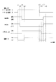
- FIG. 11 is a time chart for more specifically explaining the resistance value control accompanying the series-parallel switching of the lithium ion storage batteries 12 and 13.
- switching from the serial state to the parallel state is performed by the switching operation of the switches 21 to 25 during the period from t1 to t3.
- the switch 25 is first switched from “ON ⁇ OFF” among the switches 21 to 25 of the battery unit U, and at the subsequent timing t3, the switches 22 and 24 are switched from “OFF ⁇ ON”. Can be switched. Switching to the parallel state is completed at timing t3. At this time, since the switch 25 is turned off first, the ground fault in each lithium ion storage battery 12 and 13 is suppressed.
- the switch resistance value in the energization path of each lithium ion storage battery 12 and 13 is adjusted by feedforward control.
- the switch 22 existing in the inter-battery path in the parallel state is set as an adjustment target, and the switch is set so that an excessive current does not flow through the switch 22 in the parallel state.
- the resistance value is adjusted. That is, in the predetermined period “t1 to t4” including the timing t3 when the parallel switching is completed, the switch resistance value is adjusted by feedforward control using the parameters under the series state acquired as the parameters in the parallel state.
- the switch resistance value in the energization path of each lithium ion storage battery 12 and 13 is adjusted by feedback control.
- the switch 22 is set as an adjustment target, and the switch resistance value is adjusted so that an excessive current does not flow through the switch 22.
- switching from the parallel state to the serial state is performed by the switching operation of the switches 21 to 25 during the period from t5 to t7.
- the switches 22 and 24 are switched from “ON ⁇ OFF” first, and at the subsequent timing t7, the switch 25 is switched from “OFF ⁇ ON”. Can be switched.
- Switching to the serial state is completed at timing t7. At this time, when the switch 25 is switched to ON later, the ground fault in each lithium ion storage battery 12 and 13 is suppressed.
- the switch resistance value in the energization path of each lithium ion storage battery 12 and 13 is adjusted by feedforward control.
- the switch 25 existing in the inter-battery path in the series state is to be adjusted, and the switch is set so that an excessive current does not flow through the switch 25 in the series state.
- the resistance value is adjusted. That is, in a predetermined period “t5 to t8” including the timing t7 when the series switching is completed, the switch resistance value is adjusted by feedforward control using the parameters under the parallel state acquired as the respective parameters in the series state.
- FIG. 12 is a time chart showing changes in energization current when the lithium ion storage batteries 12 and 13 are switched from the series state to the parallel state.
- the energization current value shown in FIG. 12 is a current value that flows through the switch 22 located in the energization path between the lithium ion batteries 12 and 13 in a parallel state, and the solid line indicates the current change obtained by the control of the present embodiment.
- An alternate long and short dash line indicates a change in current when the control of this embodiment is not performed.
- a request for switching from the serial state to the parallel state occurs at timing t11, and switching from the serial state to the parallel state is completed by switching operation of the switches 21 to 25 at timing t12.
- the feedforward control is performed in a period TX (t11 to t13) including the timing t12.
- the switch resistance value in the energization path of each lithium ion storage battery 12 and 13 is adjusted by feedback control.
- the adjustment resistance value of the switch 22 is determined based on the difference ⁇ V between the terminal voltages of the lithium ion storage batteries 12 and 13.
- the energization current value is controlled with the overcurrent threshold Th as the upper limit.
- the switch resistance value becomes a small value (Rmin). As described above, generation of unnecessary loss is suppressed.
- inrush current may be generated due to discharge from the smoothing capacitor even when switching from the serial state to the parallel state.
- the inrush current can be reduced by adjusting the switch resistance value in the feedforward control.
- a switch state parameter indicating the state of a plurality of switches for series-parallel switching is acquired, and the resistance value of the switch existing in the energization path in the parallel state or series state is adjusted based on the switch state parameter. I tried to do it.
- the switch resistance value it is possible to control the current flowing through the energization path in a parallel state or a series state, that is, the current flowing between the lithium ion storage batteries 12 and 13, so that there is a variation in SOC between the storage batteries 12 and 13.
- the lithium ion storage batteries 12 and 13 can be properly used while protecting the lithium ion storage batteries 12 and 13 and the switches.
- the design margin against the overcurrent can be lowered.
- the design relating to overcurrent suppression can be omitted, which in turn can reduce the cost.
- the resistance value of the switch 22 on the parallel energization path or the series energization path in the battery unit U is changed, the resistance value of the switch 22 on the parallel energization path or the resistance value of the switch 25 on the series energization path is increased.
- the configuration is changed. That is, the configuration is such that the resistance value is changed to a larger value with respect to the full-on resistance value (minimum resistance value Rmin) of each of the switches 22 and 25. In this case, it is possible to prevent the charge / discharge current from becoming excessively large, and it is possible to realize a configuration suitable for protecting the switches 21 to 25. Further, considering that the switches 22 and 25 are constituted by semiconductor switching elements such as MOSFETs, the resistance value can be easily adjusted by controlling the gate voltage of the semiconductor switching elements.
- the necessity of current suppression is considered to change depending on the state of the switch existing on the energization path.
- the resistance value is adjusted with the switch 22 on the parallel energization path as the adjustment target based on the switch state parameter, so that the occurrence of overcurrent can be suitably suppressed.
- the switch state parameter in the parallel state is not acquired at the time when the switching is completed, the response to the instantaneous current may be delayed.
- the switch state parameter in the parallel state is obtained after the request for switching to the parallel state and before the parallel switching is completed, the switch resistance value is adjusted by feedforward control. Can respond to instantaneous current quickly.
- the resistance value of the switch 22 existing between the lithium ion storage batteries 12 and 13 is adjusted. In this case, a configuration suitable for protecting the lithium ion storage batteries 12 and 13 can be realized.
- the resistance value is adjusted with the switch 25 on the series energization path as the adjustment target based on the switch state parameter, so that the occurrence of overcurrent can be suitably suppressed.
- the response to the instantaneous current may be delayed if the switch state parameter in the serial state is not acquired when the switching is completed.
- the switch state parameter in the serial state is acquired and the switch resistance value is adjusted by feedforward control before the completion of the serial switching after the request for switching to the serial state, Can respond to instantaneous current quickly.
- the resistance value of the switch 25 between the lithium ion storage batteries 12 and 13 among the switches 23 and 25 existing on the series energization path is adjusted under the series state. In this case, a configuration suitable for protecting the lithium ion storage batteries 12 and 13 can be realized.
- the switch temperature is acquired as the switch state parameter, and the switch resistance value is adjusted based on the acquisition result.
- the feedback control is performed in consideration of the switch temperature, so that a more preferable configuration can be realized for protecting each switch.
- the switch state parameter is obtained by acquiring the energization current of any switch and adjusting the switch resistance value based on the acquisition result. In this case, feedback control can be realized according to the actual switch state.
- the magnitude of the current flowing through each of the energization paths varies depending on the storage state of the lithium ion storage batteries 12 and 13.
- the switch resistance value is adjusted based on the storage state parameter of each lithium ion storage battery 12, 13, appropriate current control can be performed in each energization path.
- the storage state parameter at least one of the charge / discharge current, terminal voltage, and SOC of each lithium ion storage battery 12 and 13 is acquired, and the switch resistance value is adjusted based on the acquisition result. In this case, feedback control can be realized in accordance with the actual storage state of each lithium ion storage battery 12, 13.
- each lithium ion storage battery 12 and 13 is acquired as a storage state parameter, and the switch resistance value is adjusted based on the acquisition result. In this case, by implementing feedback control in consideration of the battery temperature, it is possible to realize a more preferable configuration for protecting each of the storage batteries 12 and 13.
- the switch resistance value is adjusted at least during discharging or charging of each of the lithium ion storage batteries 12 and 13. Thereby, the use suitable in the battery unit U which has the lithium ion storage batteries 12 and 13 as a secondary battery is realizable.
- switches 21 to 25 are composed of semiconductor switching elements, desired current control can be easily performed by MOSFET gate voltage control or the like.
- each switch 21 to 25 a pair of MOSFETs was used, and a configuration in which the parasitic diodes of these MOSFETs were connected in series so as to be opposite to each other was adopted. As a result, when the switches 21 to 25 are turned off, the current flowing through the energization path can be suitably cut off.
- the switches 21 to 25 for switching between series and parallel are used as the resistance variable section, and the current control is performed by adjusting the switch resistance value.
- current control is performed by utilizing the on-resistance generated in each of the switches 21 to 25, so that the current flowing through each of the lithium ion storage batteries 12 and 13 and the switch can be set to a desired value without complicating the configuration. Can be controlled as follows.
- the gate voltage control is performed by digital analog control or PWM control for each of the switches 21 to 25 whose resistance value is to be adjusted. Thereby, the desired resistance value can be easily adjusted.
- PWM control theoretically, the loss due to the current becomes zero when the duty is off, so that a highly efficient system can be realized.
- the path resistance value is controlled by using the switch for series / parallel switching provided as the basic function of the battery unit U and the control unit 30 for performing the switching control, so that there is nothing to the basic unit configuration.
- a process for adjusting a desired resistance value can be realized without adding an element or the like.
- the energization current of the lithium ion storage batteries 12 and 13, the SOC may be performed using at least one of them.
- the configuration may be such that two or more of the charge / discharge current, the terminal voltage, and the SOC are acquired as the storage state parameter, and the switch resistance value is adjusted using them. In this case, by increasing the number of acquisition parameters, it is possible to improve the accuracy of current control and increase the margin for breakdown.
- the switch resistance value may be set based on the relationship shown in FIG. 9 or 10 after the “temperature” in FIG. 9 or 10 is set as the battery temperature.
- the battery temperature is a parameter that can be acquired at any timing regardless of the series-parallel state (that is, the switch state), unlike the electrical parameters such as the charge / discharge current, the terminal voltage, and the SOC.
- the thirteen states can be suitably monitored.
- the switch resistance value is set based on the switch energization current using the relationship of FIG.
- the switch resistance value is set based on the switch energization current and the switch temperature using the relationship of FIG. Also in this case, feedback control can be realized according to the actual switch state.
- the switch resistance value is adjusted using both the storage state parameter and the switch state parameter.
- the switch resistance value is changed using only one of these parameters. It is good also as a structure which adjusts.
- the resistance value adjustment is performed with the switch 22 as an adjustment target in the parallel state, and the resistance value adjustment is performed with the switch 25 as the adjustment target in the series state, but this may be changed. Any configuration may be used as long as the resistance value is adjusted by adjusting at least one of the switches 22, 23, and 24 existing in the parallel energization path in the parallel state. Moreover, what is necessary is just a structure which adjusts resistance value by making at least 1 of the switches 23 and 25 which exist in a series electricity supply path
- the switch for obtaining the switch state parameter may be different from the switch for resistance adjustment.
- a switch state parameter is acquired for the switch 22 among the switches 22, 23, and 24 existing in the parallel energization path in the parallel state, and the resistance value is adjusted for either of the switches 23 and 24.
- the switch state parameter is acquired for the switch 23 and the resistance value is adjusted for the switch 25.
- An overcurrent threshold for determining that an overcurrent has flowed through the energization path including the path between the lithium ion storage batteries 12 and 13 is determined, and the control unit 30 determines whether there is an overcurrent based on the overcurrent threshold. It is good also as a structure to determine. In such a case, the control unit 30 is configured to set the overcurrent threshold based on at least one of the charge / discharge current, the terminal voltage, the SOC, and the battery temperature as the storage state parameter. At this time, if the overcurrent is likely to flow, the overcurrent threshold may be reduced. It is also possible to adopt a configuration in which the overcurrent threshold is set based on at least one of the switch energization current and the switch temperature as the switch state parameter.
- a configuration using a battery other than the lithium ion storage battery may be used as the plurality of power storage means.
- any of a configuration using a storage battery other than a lithium ion storage battery, a configuration using a storage battery and a capacitor, and a configuration using a plurality of capacitors may be used as the plurality of power storage means.
- the resistance value at the time of switching on the switch for series-parallel switching of a plurality of lithium ion batteries is adjusted, and thereby the charge / discharge current for each lithium ion battery is individually controlled. May be changed.
- another switch composed of a semiconductor switching element is provided in addition to the switch for series / parallel switching, and the on-resistance value of the other switch is adjusted, thereby charging and discharging each lithium ion storage battery. It is good also as a structure which controls an electric current separately.
- variable resistance portion In addition to using a semiconductor switching element as the variable resistance portion, it is also possible to use a variable resistor.
Abstract
Ce système d'alimentation électrique comprend : une pluralité de moyens de stockage d'électricité (12, 13); et une unité de sélection qui comporte une pluralité de moyens de commutation (21 à 25) disposés sur des trajets électriques qui se connectent à chacun des moyens de stockage d'électricité, et qui sélectionne entre un état parallèle dans lequel la pluralité de moyens de stockage d'électricité sont connectés les uns aux autres en parallèle, et un état en série dans lequel la pluralité de moyens de stockage d'électricité sont connectés les uns aux autres en série. Le dispositif de commande d'alimentation électrique (30) comprend : une unité d'acquisition qui acquiert un paramètre d'état de commutation qui est corrélé à l'amplitude du courant circulant sur le trajet conducteur de courant qui comprend un trajet entre chacun des moyens de stockage d'électricité dans l'état parallèle ou dans l'état de série, en tant que paramètre indiquant l'état de la pluralité de moyens de commutation; et une unité de commande de résistance qui ajuste la valeur de résistance d'une résistance variable présente sur le trajet conducteur de courant à l'état parallèle ou à l'état en série sur la base du paramètre d'état de commutation.
Priority Applications (1)
| Application Number | Priority Date | Filing Date | Title |
|---|---|---|---|
| DE112017003481.7T DE112017003481T5 (de) | 2016-07-11 | 2017-07-10 | Leistungszufuhrsteuerungsvorrichtung und leistungszufuhrsystem |
Applications Claiming Priority (2)
| Application Number | Priority Date | Filing Date | Title |
|---|---|---|---|
| JP2016136630A JP6878782B2 (ja) | 2016-07-11 | 2016-07-11 | 電源制御装置、及び電源システム |
| JP2016-136630 | 2016-07-11 |
Publications (1)
| Publication Number | Publication Date |
|---|---|
| WO2018012471A1 true WO2018012471A1 (fr) | 2018-01-18 |
Family
ID=60952475
Family Applications (1)
| Application Number | Title | Priority Date | Filing Date |
|---|---|---|---|
| PCT/JP2017/025181 WO2018012471A1 (fr) | 2016-07-11 | 2017-07-10 | Dispositif de commande d'alimentation électrique et système d'alimentation électrique |
Country Status (3)
| Country | Link |
|---|---|
| JP (1) | JP6878782B2 (fr) |
| DE (1) | DE112017003481T5 (fr) |
| WO (1) | WO2018012471A1 (fr) |
Cited By (4)
| Publication number | Priority date | Publication date | Assignee | Title |
|---|---|---|---|---|
| WO2019065236A1 (fr) * | 2017-09-29 | 2019-04-04 | 株式会社デンソー | Dispositif de commande d'alimentation électrique |
| CN113890370A (zh) * | 2021-09-29 | 2022-01-04 | 西安领充创享新能源科技有限公司 | 串并联切换电路控制方法、装置、控制器及存储介质 |
| JP7354919B2 (ja) | 2020-05-08 | 2023-10-03 | 株式会社豊田自動織機 | 電力変換装置 |
| JP7354918B2 (ja) | 2020-05-08 | 2023-10-03 | 株式会社豊田自動織機 | 電力変換装置 |
Families Citing this family (3)
| Publication number | Priority date | Publication date | Assignee | Title |
|---|---|---|---|---|
| US10800285B2 (en) * | 2019-03-01 | 2020-10-13 | GM Global Technology Operations LLC | System to modulate switch resistances within a battery system |
| JP7224973B2 (ja) * | 2019-03-08 | 2023-02-20 | マレリ株式会社 | 電源システム |
| JP7347048B2 (ja) * | 2019-09-12 | 2023-09-20 | 株式会社豊田自動織機 | 接続回路及び二次電池システム |
Citations (3)
| Publication number | Priority date | Publication date | Assignee | Title |
|---|---|---|---|---|
| JPH11299119A (ja) * | 1998-04-09 | 1999-10-29 | Okamura Kenkyusho:Kk | 直並列切換電源装置 |
| JP2007274830A (ja) * | 2006-03-31 | 2007-10-18 | Nissan Motor Co Ltd | 車両用電力供給装置 |
| WO2013076877A1 (fr) * | 2011-11-25 | 2013-05-30 | 株式会社日立製作所 | Système de batterie de stockage |
Family Cites Families (3)
| Publication number | Priority date | Publication date | Assignee | Title |
|---|---|---|---|---|
| JP3925166B2 (ja) | 2001-11-20 | 2007-06-06 | 株式会社デンソー | エンジン自動始動システム |
| JP4782072B2 (ja) * | 2007-05-18 | 2011-09-28 | パナソニック株式会社 | 電源装置 |
| JP6134918B2 (ja) | 2016-02-26 | 2017-05-31 | パナソニックIpマネジメント株式会社 | 太陽電池モジュール |
-
2016
- 2016-07-11 JP JP2016136630A patent/JP6878782B2/ja active Active
-
2017
- 2017-07-10 DE DE112017003481.7T patent/DE112017003481T5/de active Pending
- 2017-07-10 WO PCT/JP2017/025181 patent/WO2018012471A1/fr active Application Filing
Patent Citations (3)
| Publication number | Priority date | Publication date | Assignee | Title |
|---|---|---|---|---|
| JPH11299119A (ja) * | 1998-04-09 | 1999-10-29 | Okamura Kenkyusho:Kk | 直並列切換電源装置 |
| JP2007274830A (ja) * | 2006-03-31 | 2007-10-18 | Nissan Motor Co Ltd | 車両用電力供給装置 |
| WO2013076877A1 (fr) * | 2011-11-25 | 2013-05-30 | 株式会社日立製作所 | Système de batterie de stockage |
Cited By (5)
| Publication number | Priority date | Publication date | Assignee | Title |
|---|---|---|---|---|
| WO2019065236A1 (fr) * | 2017-09-29 | 2019-04-04 | 株式会社デンソー | Dispositif de commande d'alimentation électrique |
| JP2019068624A (ja) * | 2017-09-29 | 2019-04-25 | 株式会社デンソー | 電源制御装置 |
| JP7354919B2 (ja) | 2020-05-08 | 2023-10-03 | 株式会社豊田自動織機 | 電力変換装置 |
| JP7354918B2 (ja) | 2020-05-08 | 2023-10-03 | 株式会社豊田自動織機 | 電力変換装置 |
| CN113890370A (zh) * | 2021-09-29 | 2022-01-04 | 西安领充创享新能源科技有限公司 | 串并联切换电路控制方法、装置、控制器及存储介质 |
Also Published As
| Publication number | Publication date |
|---|---|
| JP6878782B2 (ja) | 2021-06-02 |
| JP2018011372A (ja) | 2018-01-18 |
| DE112017003481T5 (de) | 2019-03-28 |
Similar Documents
| Publication | Publication Date | Title |
|---|---|---|
| WO2018012471A1 (fr) | Dispositif de commande d'alimentation électrique et système d'alimentation électrique | |
| RU2592468C1 (ru) | Устройство управления подачей энергии | |
| CN105936248B (zh) | 电源系统 | |
| CN110192320B (zh) | 电源装置和电源系统 | |
| JP6460875B2 (ja) | バッテリシステム制御装置 | |
| CN108352714B (zh) | 电源装置及电池单元 | |
| JP6090195B2 (ja) | 電池ユニット | |
| JP6468138B2 (ja) | 電源装置 | |
| JP6546422B2 (ja) | バッテリシステム制御装置 | |
| US10144373B2 (en) | Power supply system control device and power supply system control method | |
| WO2018008567A1 (fr) | Dispositif et système de commande de source d'alimentation | |
| WO2018061681A1 (fr) | Système d'alimentation électrique et unité de batterie | |
| JP2020100259A (ja) | 車両用電源装置 | |
| WO2018008566A1 (fr) | Dispositif de commande de source d'alimentation et système de source d'alimentation | |
| WO2018012470A1 (fr) | Dispositif de commande d'alimentation électrique et système d'alimentation électrique | |
| US11804726B2 (en) | In-vehicle auxiliary power source control device and in-vehicle auxiliary power source device | |
| JP2018046635A (ja) | スイッチ制御装置、電源ユニット及び電源システム | |
| WO2020209132A1 (fr) | Dispositif de commande destiné à un dispositif d'alimentation électrique | |
| WO2017065161A1 (fr) | Dispositif d'alimentation électrique et pile | |
| CN108352719B (zh) | 电源装置 | |
| JP6626741B2 (ja) | バッテリシステム制御装置 | |
| JP7249900B2 (ja) | 車両用電源装置 | |
| WO2020203465A1 (fr) | Dispositif source de puissance | |
| JP7339795B2 (ja) | 車両用電源装置 | |
| JP6936683B2 (ja) | 車両用電源システム及び車両用電源システムの制御装置 |
Legal Events
| Date | Code | Title | Description |
|---|---|---|---|
| 121 | Ep: the epo has been informed by wipo that ep was designated in this application |
Ref document number: 17827598 Country of ref document: EP Kind code of ref document: A1 |
|
| 122 | Ep: pct application non-entry in european phase |
Ref document number: 17827598 Country of ref document: EP Kind code of ref document: A1 |