WO2018008567A1 - Dispositif et système de commande de source d'alimentation - Google Patents
Dispositif et système de commande de source d'alimentation Download PDFInfo
- Publication number
- WO2018008567A1 WO2018008567A1 PCT/JP2017/024266 JP2017024266W WO2018008567A1 WO 2018008567 A1 WO2018008567 A1 WO 2018008567A1 JP 2017024266 W JP2017024266 W JP 2017024266W WO 2018008567 A1 WO2018008567 A1 WO 2018008567A1
- Authority
- WO
- WIPO (PCT)
- Prior art keywords
- power storage
- state
- unit
- lithium ion
- resistance value
- Prior art date
Links
Images


Classifications
-
- H—ELECTRICITY
- H01—ELECTRIC ELEMENTS
- H01M—PROCESSES OR MEANS, e.g. BATTERIES, FOR THE DIRECT CONVERSION OF CHEMICAL ENERGY INTO ELECTRICAL ENERGY
- H01M10/00—Secondary cells; Manufacture thereof
- H01M10/42—Methods or arrangements for servicing or maintenance of secondary cells or secondary half-cells
- H01M10/44—Methods for charging or discharging
-
- H—ELECTRICITY
- H01—ELECTRIC ELEMENTS
- H01M—PROCESSES OR MEANS, e.g. BATTERIES, FOR THE DIRECT CONVERSION OF CHEMICAL ENERGY INTO ELECTRICAL ENERGY
- H01M10/00—Secondary cells; Manufacture thereof
- H01M10/42—Methods or arrangements for servicing or maintenance of secondary cells or secondary half-cells
- H01M10/48—Accumulators combined with arrangements for measuring, testing or indicating the condition of cells, e.g. the level or density of the electrolyte
-
- H—ELECTRICITY
- H02—GENERATION; CONVERSION OR DISTRIBUTION OF ELECTRIC POWER
- H02J—CIRCUIT ARRANGEMENTS OR SYSTEMS FOR SUPPLYING OR DISTRIBUTING ELECTRIC POWER; SYSTEMS FOR STORING ELECTRIC ENERGY
- H02J7/00—Circuit arrangements for charging or depolarising batteries or for supplying loads from batteries
-
- Y—GENERAL TAGGING OF NEW TECHNOLOGICAL DEVELOPMENTS; GENERAL TAGGING OF CROSS-SECTIONAL TECHNOLOGIES SPANNING OVER SEVERAL SECTIONS OF THE IPC; TECHNICAL SUBJECTS COVERED BY FORMER USPC CROSS-REFERENCE ART COLLECTIONS [XRACs] AND DIGESTS
- Y02—TECHNOLOGIES OR APPLICATIONS FOR MITIGATION OR ADAPTATION AGAINST CLIMATE CHANGE
- Y02E—REDUCTION OF GREENHOUSE GAS [GHG] EMISSIONS, RELATED TO ENERGY GENERATION, TRANSMISSION OR DISTRIBUTION
- Y02E60/00—Enabling technologies; Technologies with a potential or indirect contribution to GHG emissions mitigation
- Y02E60/10—Energy storage using batteries
Definitions
- the present disclosure relates to a power supply control device applied to a power supply system including a plurality of power storage means and a power supply system.
- connection switching means such as a relay and a switch are provided on each energization path leading to the plurality of storage batteries.
- the difference in the number of relays and switches on the energization path in the series / parallel state causes a difference in the resistance value of the energization path in each storage battery. Therefore, a difference arises in the charging / discharging current which flows through a some storage battery, and dispersion
- SOC electrical residual capacity
- the present disclosure has been made in view of the above problems, and a main purpose thereof is a power supply control device capable of suppressing capacity variation in each power storage unit, and thus allowing appropriate charge / discharge in each power storage unit, And providing a power supply system.
- the power supply control device of the present disclosure includes a plurality of power storage means and a plurality of switch means provided in an electrical path leading to each power storage means, and the plurality of power storage means connected in parallel to each other and connected in series to each other A plurality of power storage means, wherein the plurality of power storage means includes a first power storage means whose positive side is connected to a low voltage load of a low voltage system in the series state, and a high voltage in the series state.
- the present invention is applied to a power supply system including a second power storage unit having a positive electrode connected to a high voltage load of the system.
- the power supply control device includes a capacity acquisition unit that acquires the remaining electric capacity of each of the plurality of power storage units, and an electric power of each power storage unit acquired by the capacity acquisition unit when the plurality of power storage units are in a parallel state. Based on the remaining capacity, the resistance existing in the electrical path leading to each power storage means so that the difference between the remaining electrical capacity of the first power storage means and the remaining power capacity of the second power storage means becomes a desired amount.
- a current control unit that adjusts a resistance value of the variable unit to control a charge / discharge current for each power storage unit.
- a plurality of power storage means capable of switching in series and parallel are provided, of which the first power storage means is connected in series to the low voltage load of the low voltage system, and the second power storage means is connected in series to the high voltage system.
- the discharge current differs greatly between the first power storage means and the second power storage means in a series state, resulting in a large difference in the remaining electric capacity (SOC). It is possible to become.
- the difference when a plurality of power storage units are in a parallel state, based on the electrical remaining capacity of each power storage unit, the difference between the electrical remaining capacity of the first power storage unit and the remaining electrical capacity of the second power storage unit.
- the charge / discharge current is controlled for each power storage means by adjusting the resistance value of the resistance variable portion existing in the electrical path leading to each power storage means so that the desired amount is obtained.
- the electric storage capacity is intentionally set to a desired amount by the first power storage means and the second power storage means in anticipation that each power storage means is subsequently switched to the serial state. The difference is given.
- a configuration in which a plurality of power storage units may be any configuration having two or more power storage units that can be switched in series-parallel, for example, three or more power storage units.
- a configuration in which series-parallel switching is performed for at least two of the power storage units is also included.
- the remaining electrical capacity of the power storage means may indicate the amount of electricity remaining in the total electrical capacity that can be stored in the power storage means, and may include detection errors, redundant use areas, deterioration margins, etc. in the power storage means. It may indicate the amount of electricity remaining in the excluded usable area.
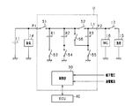
- FIG. 1 is an electric circuit diagram showing the power supply system in the first embodiment.
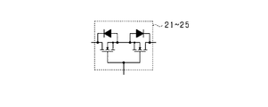
- FIG. 2 is a diagram showing a specific configuration of the switch.
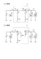
- 3A is a diagram showing a state in which lithium ion storage batteries are connected in parallel
- FIG. 3B is a diagram showing a state in which lithium ion storage batteries are connected in series
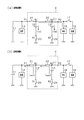
- 4A is a diagram showing a current flow during parallel charging
- FIG. 4B is a diagram showing a current flow during parallel discharging
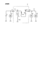
- FIG. 5 is a diagram showing the flow of current during series discharge
- FIG. 1 is an electric circuit diagram showing the power supply system in the first embodiment.
- FIG. 2 is a diagram showing a specific configuration of the switch.
- 3A is a diagram showing a state in which lithium ion storage batteries are connected in parallel
- FIG. 3B is a diagram showing a state in which lithium ion storage batteries are connected in series
- 4A is a diagram showing a current flow during parallel charging
- FIG. 4B is a diagram showing
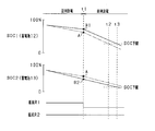
- FIG. 6 is a time chart showing transitions of SOC1 and SOC2 of each lithium ion storage battery at the time of parallel discharge and at the time of series discharge.
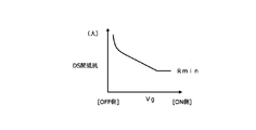
- FIG. 7 is a diagram illustrating the relationship between the gate voltage and the drain-source resistance.
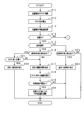
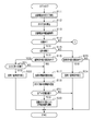
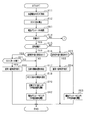
- FIG. 8 is a flowchart showing a processing procedure for controlling the connection state and charge / discharge current of the lithium ion storage battery
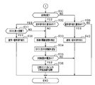
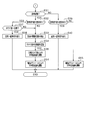
- FIG. 9 is a flowchart showing a processing procedure following FIG.
- FIG. 10 is a diagram illustrating the relationship between the SOC difference and the switch resistance value.
- FIG. 11 is an electric circuit diagram showing a power supply system in the second embodiment.
- FIG. 12 is a diagram showing a state in which lithium ion storage batteries are connected in series, FIG.
- FIG. 13 is a flowchart showing a processing procedure for controlling the connection state and charge / discharge current of the lithium ion storage battery in the second embodiment.
- FIG. 14 is a flowchart showing a processing procedure following FIG.
- FIG. 15 is a flowchart showing a processing procedure for controlling the connection state and charge / discharge current of the lithium ion storage battery in the third embodiment.
- FIG. 16 is a flowchart showing the processing procedure following FIG.
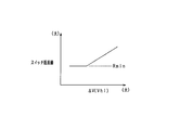
- FIG. 17 is a diagram illustrating the relationship between the terminal voltage difference ⁇ V and the switch resistance value.
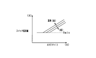
- FIG. 18 is a diagram illustrating a relationship among a terminal voltage difference ⁇ V, a battery temperature, and a switch resistance value.
- an in-vehicle power supply device that supplies electric power to various devices of the vehicle in a vehicle that runs using an engine (internal combustion engine) as a drive source is embodied.
- the power supply system is a so-called dual power supply system including a first power storage device having a lead storage battery and a second power storage device having a plurality of lithium ion storage batteries as the power storage device. .
- the power supply system includes a lead storage battery 11 and two lithium ion storage batteries 12 and 13, and from each storage battery 11 to 13 to various electric loads 14 and 15 and a rotating electrical machine 16. Can be fed. Further, each of the storage batteries 11 to 13 can be charged by the rotating electrical machine 16.
- the lead storage battery 11 is a well-known general-purpose storage battery.
- the lithium ion storage batteries 12 and 13 are high-density storage batteries that have less power loss in charge and discharge and higher output density and energy density than the lead storage battery 11.
- the lithium ion storage batteries 12 and 13 may be storage batteries having higher energy efficiency during charging / discharging than the lead storage battery 11.
- the lithium ion storage batteries 12 and 13 are each configured as an assembled battery having a plurality of single cells.
- the rated voltages of the storage batteries 11 to 13 are the same, for example, 12V.
- the two lithium ion storage batteries 12 and 13 are housed in a housing case and configured as an integral battery unit U.
- the battery unit U has two output terminals P1 and P2, among which the lead storage battery 11 and the electric load 14 are connected to the output terminal P1, and the electric load 15 and the rotating electrical machine 16 are connected to the output terminal P2. Has been.
- the electrical load 14 connected to the output terminal P1 is a 12V system load driven based on 12V power supply from the lead storage battery 11 or the lithium ion storage batteries 12 and 13.
- the electric load 14 includes a constant voltage request load that is required to be constant or at least stable so that the voltage of the supplied power fluctuates within a predetermined range, and a general electric load other than the constant voltage request load. It is.
- the constant voltage required load is a load to be protected and is a load in which power supply failure is not allowed. Specific examples of the constant voltage required load include various ECUs such as a navigation device, an audio device, a meter device, and an engine ECU.
- the electric load 15 is a high-voltage load in which a large driving force is temporarily required, for example, when the vehicle is traveling, that is, a high power requirement may occur.
- a specific example is an electric steering device.
- the electric load 14 connected to the output terminal P1 corresponds to a low voltage electric load
- the electric load 15 and the rotating electrical machine 16 connected to the output terminal P2 correspond to a high voltage electric load.
- the rotating shaft of the rotating electrical machine 16 is drivingly connected to an engine output shaft (not shown) by a belt or the like.
- the rotating shaft of the rotating electrical machine 16 is rotated by the rotation of the engine output shaft, while the rotating shaft of the rotating electrical machine 16 is rotated.
- the rotating electrical machine 16 is an MG (Motor Generator), and has a power generation function for generating power (regenerative power generation) by rotation of the engine output shaft and the axle, and a power running function for applying rotational force to the engine output shaft.
- the rotating electrical machine 16 is configured to perform adjustment of the generated current during power generation and torque adjustment during powering driving by an inverter as a power conversion device provided integrally or separately.
- the engine is started and torque assist is performed by driving the rotating electrical machine 16.
- the rotating electrical machine 16 is an electric load in terms of adding power to the engine output shaft, and is a high power / high current load in comparison with the electric load 14.
- a switch 17 is provided between the electric load 15 and the rotating electrical machine 16, and the storage batteries 11 to 13 and the rotating electrical machine 16 and the electrical load 15 are electrically connected or disconnected by turning on or off the switch 17. It is like that.
- the two lithium ion storage batteries 12 and 13 can be switched between a parallel connection state and a serial connection state, which will be described in detail.
- switches 21 and 22 are provided in series on the electric path L1 between the output terminals P1 and P2.
- the electrical path L1 is also a part of the energization path where the electrical loads 14 and 15 and the rotating electrical machine 16 are connected to the lead storage battery 11 in the present system.
- the positive terminal (positive terminal) of the lithium ion storage battery 12 is connected to the first point N1 between the switches 21 and 22, and the positive terminal of the lithium ion storage battery 13 is connected to the second point N2 between the switch 22 and the output terminal P2. It is connected.
- switches 23 and 24 are provided between the negative terminals of the lithium ion storage batteries 12 and 13 and the ground, respectively.
- the first point N1 is connected to a third point N3 between the negative terminal of the lithium ion storage battery 13 and the switch 24, and a switch 25 is provided in the connection path.
- the switches 21 to 25 correspond to “switching units”.
- Each of the switches 21 to 25 is composed of a semiconductor switching element such as a MOSFET, IGBT, or bipolar transistor.
- each of the switches 21 to 25 is configured by a MOSFET, and the switches 21 to 25 are turned on and off according to application of a predetermined gate voltage.
- each of the switches 21 to 25 is configured to have two sets of MOSFETs, and the parasitic diodes of each set of MOSFETs are connected in series so that they are opposite to each other. Good.
- the parasitic diodes that are opposite to each other completely cut off the current that flows through the path in which the switches 21 to 25 are turned off.
- the configuration using semiconductor switching elements in each of the switches 21 to 25 may be arbitrary. For example, a configuration in which parasitic diodes of MOSFETs are not arranged in opposite directions may be used.
- FIG. 3A shows a state in which the lithium ion storage batteries 12 and 13 are connected in parallel
- FIG. 3B shows a state in which the lithium ion storage batteries 12 and 13 are connected in series.
- the energization path shown in FIG. 3A is a “parallel energization path”
- the energization path shown in FIG. 3B is a “series energization path”.
- the switch 17 is turned off in the parallel state and turned on as necessary in the series state.
- the switches 21 to 24 are turned on and the switch 25 is turned off.
- the lithium ion storage batteries 12 and 13 are in a parallel relationship.
- the output voltages of the output terminals P1 and P2 are both approximately 12V.
- the lead storage battery 11 and the lithium ion storage batteries 12 and 13 are connected in parallel to the electric load 14 on the P1 side, and the lead storage battery 11 and the lithium ion storage battery are connected in parallel to the rotating electrical machine 16 on the P2 side. 12 and 13 are connected.
- the electrical load 14 is connected to an intermediate position (first point N1) on the path connecting the positive electrodes of the lithium ion storage batteries 12 and 13 together.
- the switches 21, 23 and 25 are on and the switches 22 and 24 are off.
- the lithium ion storage batteries 12 and 13 are connected in series. It has become.
- the output voltage of the output terminal P1 is approximately 12V
- the output voltage of the output terminal P2 is approximately 24V.
- the lead storage battery 11 and the lithium ion storage battery 12 are connected in parallel to the electric load 14 on the P1 side.
- lithium ion storage batteries 12 and 13 are connected in series to the rotating electrical machine 16 on the P2 side.
- the rotating electrical machine 16 is connected to a position (second point N2) on the positive electrode side of the storage battery 13 on the high voltage side among the lithium ion storage batteries 12 and 13.
- the rotating electrical machine 16 is capable of 12V powering driving with a power supply voltage of 12V and 24V powering driving with a power supply voltage of 24V.
- the rotating electrical machine 16 When the lithium ion storage batteries 12 and 13 are connected in parallel, the rotating electrical machine 16 The rotary electric machine 16 is driven by 24V in a state where the battery is driven by 12V and the lithium ion batteries 12 and 13 are connected in series.
- the electric load 15 connected to the output terminal P2 is driven by 24V with the lithium ion storage batteries 12 and 13 connected in series.
- the battery unit U has a control unit 30 constituting battery control means.
- the control unit 30 switches on / off (opening / closing) the switches 21 to 25 in the battery unit U.
- the control unit 30 controls on / off of the switches 21 to 25 based on the running state of the vehicle and the storage states of the storage batteries 11 to 13.
- charging / discharging is implemented using the lead storage battery 11 and the lithium ion storage batteries 12 and 13 selectively.
- the charge / discharge control based on the storage state of each of the storage batteries 11 and 12 will be briefly described.
- each lithium ion storage battery 12 and 13 is each provided with the voltage sensor which detects a terminal voltage for every storage battery, and the current sensor which detects an energization current for every storage battery, respectively.
- the detection result of the sensor is input to the control unit 30.
- the control unit 30 sequentially acquires the terminal voltage detection values of the lead storage battery 11 and the lithium ion storage batteries 12 and 13 and sequentially acquires the energization currents of the lead storage battery 11 and the lithium ion storage batteries 12 and 13. And based on these acquired values, while calculating OCV (open circuit voltage: OpenageCircuit Voltage) and SOC (residual capacity: State Of Charge) of the lead storage battery 11 and the lithium ion storage batteries 12, 13, the OCV and SOC are calculated. The amount of charge and the amount of discharge to the lithium ion storage batteries 12 and 13 are controlled so as to be maintained within a predetermined use range.
- OCV open circuit voltage: OpenageCircuit Voltage
- SOC residual capacity: State Of Charge
- the lithium ion storage batteries 12 and 13 are basically brought into a parallel state so that the load drive request on the output terminal P2 side and the high voltage power generation for the rotating electrical machine 16 are performed.
- Each of the lithium ion storage batteries 12 and 13 can be switched to a series state in response to the above request.
- the control unit 30 temporarily switches the lithium ion storage batteries 12 and 13 from the parallel state to the serial state based on, for example, a drive request for the electric steering device (electric load 15) or a torque assist request by the rotating electrical machine 16. Implement control.
- the ECU 40 is connected to the control unit 30.
- the control unit 30 and the ECU 40 are connected by a communication network such as CAN and can communicate with each other, and various data stored in the control unit 30 and the ECU 40 can be shared with each other.
- the ECU 40 is an electronic control device having a function of performing idling stop control of the vehicle.
- the idling stop control automatically stops the engine when a predetermined automatic stop condition is satisfied, and restarts the engine when the predetermined restart condition is satisfied under the automatic stop state.
- the engine is started by the rotating electric machine 16 when the idling stop control is automatically restarted.
- FIG. 4A shows the current flow during parallel charging
- FIG. 4B shows the current flow during parallel discharging.
- a generated current is output from the rotating electrical machine 16, and the lead storage battery 11 and the lithium ion storage batteries 12 and 13 are charged and the electric load 14 is fed by the generated current.
- the switches 22 and 23 exist in the charging path of the lithium ion storage battery 12, and the charging current Iin 1 flows according to the path resistance including the switches 22 and 23.
- a switch 24 exists in the charging path to the lithium ion storage battery 13, and a charging current Iin 2 flows according to path resistance including the switch 24.
- the lithium ion storage battery 13 discharges with the electric load 15 and the rotating electrical machine 16 being discharged, whereas the lithium ion storage battery 12 has the electrical load 15 and the rotating electrical machine. In addition to 16, the electric load 14 is discharged. Therefore, the discharge current Iout1 of the lithium ion storage battery 12 becomes larger than the discharge current Iout2 of the lithium ion storage battery 13, thereby further increasing the SOC difference between the storage batteries 12 and 13.
- the SOC of each lithium ion storage battery 12 and 13 is varied, there is a disadvantage that the use area of each storage battery 12 and 13 cannot be fully utilized.
- the lithium ion storage battery 12 is connected in series to the electric load 14 that is a low-voltage load, and this corresponds to the “first power storage means”.
- the lithium ion storage battery 13 is connected in series to an electric load 15 or a rotating electrical machine 16 that is a high voltage load, and this corresponds to the “second power storage means”.
- the control unit 30 corresponds to a “capacity acquisition unit” and a “current control unit”.
- the solid line shows the SOC change when a desired amount of difference is intentionally given to SOC1 and SOC2 in the present embodiment, and the alternate long and short dash line equalizes SOC1 and SOC2 as a comparative example.
- the SOC change in the case of performing is shown.
- SOC1 is shown in the upper diagram and SOC2 is shown separately in the lower diagram.
- the difference between the discharge currents Iout1 and Iout2 of the lithium ion storage batteries 12 and 13 is caused by the difference in the switches on the discharge path, whereas in FIG.
- the difference between the discharge currents Iout1 and Iout2 of the lithium ion storage batteries 12 and 13 is caused by the difference between the discharge targets of the storage batteries 12 and 13, and the latter (during series discharge) is the discharge current. The difference is considered to increase.
- the resistance value in the energization path of the lithium ion storage battery 12 is made relatively larger than the resistance value in the energization path of the lithium ion storage battery 13.
- the discharge currents of the storage batteries 12 and 13 are controlled. More specifically, in FIG. 4B, the discharge current Iout1 of the lithium ion storage battery 12 is reduced by increasing the resistance value R1 of the switch 23 provided in the energization path of the lithium ion storage battery 12. In this case, by using the relationship between the gate voltage Vg and the drain-source resistance shown in FIG.
- the drain-source resistance by controlling the gate voltage Vg, the resistance value R1 of the switch 23, and consequently the lithium ion storage battery 12 side Change the path resistance value.
- the relationship in which the drain-source resistance increases by lowering the gate voltage Vg is defined with reference to the resistance value Rmin in the normally on state, and the switch resistance value (drain-source resistance) is higher than Rmin. It is variably set to the larger side.
- a predetermined difference is given to the SOC of each of the lithium ion storage batteries 12 and 13 as described above even in the parallel charge state.
- the resistance value in the energization path of the lithium ion storage battery 13 is made relatively larger than the resistance value in the energization path of the lithium ion storage battery 12 to control the charging current of each of the storage batteries 12 and 13. More specifically, in FIG. 4A, the charging current Iin2 of the lithium ion storage battery 13 is reduced by increasing the resistance value R2 of the switch 24 provided in the energization path of the lithium ion storage battery 13. In this case, by using the relationship of FIG. 7 and adjusting the drain-source resistance by controlling the gate voltage Vg, the resistance value R2 of the switch 24 and thus the path resistance value on the lithium ion storage battery 13 side are changed.
- FIGS. 8 and 9 are flowcharts showing a processing procedure for controlling the connection state and charging / discharging current of each lithium ion storage battery 12, 13, and this processing is repeatedly performed by the control unit 30 at a predetermined cycle.
- step S11 the SOC of each lithium ion storage battery 12 and 13 is acquired, and in the subsequent step S12, the SOC difference of each lithium ion storage battery 12 and 13 is calculated. Then, in step S13, the energization current value of each lithium ion storage battery 12 and 13 is acquired.
- step S14 it is determined whether or not the battery unit U is in the charged state. If the battery unit U is in the charged state, the process proceeds to step S15. If the battery unit U is not in the charged state, the process proceeds to step S31 in FIG.
- step S14 it is determined that the state of charge is in the charged state when the amount of power generation of the rotating electrical machine 16 is greater than the amount of power supplied to the load, and the state of discharge is determined when the amount of power supplied to the load is greater than the amount of power generated by the rotating electrical machine 16. It is determined. However, it may be determined whether or not the rotating electrical machine 16 is in a charged state depending on whether or not the rotating electrical machine 16 is in a power generating state.
- step S15 it is determined whether or not each of the lithium ion storage batteries 12 and 13 is in a parallel state. If the lithium ion storage batteries 12 and 13 are in a parallel state, the process proceeds to the subsequent step S16.
- step S16 it is determined whether or not a request for switching from the parallel state to the serial state has occurred for the lithium ion storage batteries 12 and 13. If no switching request is generated, the process proceeds to step S17, and the current control for each of the lithium ion storage batteries 12 and 13 is performed by the processes in steps S17 to S20.
- step S17 the drive state (power supply state) of each electric load 14, 15 is detected.
- step S18 the target value of the SOC difference in each lithium ion storage battery 12, 13 is determined based on the load drive state. Set. Specifically, in step S17, it is detected whether each of the electric loads 14 and 15 is in a drive-on state or a drive-off state. If the electric load 14 on the output terminal P1 side of the electric loads 14 and 15 is in the drive-on state, in step S18, it is anticipated that “Iout1> Iout2” will be obtained under the parallel discharge state, and each lithium ion storage battery The target value of the SOC difference is set so that the SOCs 12 and 13 are “SOC1> SOC2”.
- a target value of the SOC difference may be set based on the required power of the electric load 14. For example, the target value of the SOC difference is increased as the required power of the electric load 14 is increased.
- the target SOC of each of the lithium ion storage batteries 12 and 13 may be set based on the total required power by the electric loads 14 and 15, for example, the target SOC is increased as the total required power is larger.
- the target value of the SOC difference may be set based on which of the plurality of loads is in a driving state. For example, assuming that only one of the headlight and the wiper device as the electric load 14 is driven or both are driven, the target value of the SOC difference in the case of both driving is set as the SOC in the case of the one driving. It may be larger than the difference target value. However, in steps S17 and S18, it is also possible to set a predetermined value as a target value of the SOC difference satisfying “SOC1> SOC2”.
- step S19 when adjusting the path resistance value, it is determined whether or not the value of the energization current flowing through the target path on which the resistance value adjustment is performed is smaller than a predetermined value.
- a predetermined value it is determined whether or not an energization current value (Iin2 in FIG. 4A) flowing in the energization path of the storage battery 13 among the lithium ion storage batteries 12 and 13 is smaller than a predetermined value. If step S19 is YES, it will progress to subsequent step S20, and if step S19 is NO, this process will be complete
- step S20 the resistance value of the switch 24 to be adjusted is adjusted.
- gate voltage control is performed based on the target value of the SOC difference, and the switch 24 is changed to the side where the resistance value in the ON state is increased.
- the switch resistance value is set according to the SOC difference using the relationship of FIG. In FIG. 10, a relationship is defined in which the switch resistance value increases as the SOC difference increases.
- the switch resistance value is set according to the energization current value of the lithium ion storage battery 13. Specifically, considering that the energization current value is large, the energy loss in the resistance portion is increased. The larger the energization current value is, the smaller the switch resistance value is set.
- the control unit 30 adjusts the switch resistance value by digital analog control or PWM control (the same applies to step S36 described later).
- the path resistance value of the lithium ion storage battery 13 becomes larger than the path resistance value of the lithium ion storage battery 12, whereby the charging currents of the lithium ion storage batteries 12 and 13 are individually controlled. Will be.
- step S16 If it is determined in step S16 that a request for switching from the parallel state to the serial state has occurred, the process proceeds to step S21, and whether or not the SOC difference between the lithium ion storage batteries 12 and 13 matches the target value. judge. Specifically, it is determined whether or not the actual SOC difference is within a predetermined range determined based on the target value. The predetermined range is defined by an upper limit value and a lower limit value. If the SOC difference matches the target value, the process proceeds to step S22, and switching from the parallel state to the serial state is performed. If the SOC difference does not match the target value, the process proceeds to step S17, and the above-described resistance adjustment process is performed (steps S17 to S20).
- step S15 If it is determined in step S15 that the state is not the parallel state but the series state, the process proceeds to step S23 to determine whether or not a request for switching from the series state to the parallel state has occurred for the lithium ion batteries 12 and 13. . If a switching request is generated, the process proceeds to step S24, and switching from the serial state to the parallel state is performed. If no switching request is generated, the process is terminated as it is.
- step S14 determines whether the battery is in a discharged state instead of a charged state. If it is determined in step S31 in FIG. 9 whether each of the lithium ion storage batteries 12 and 13 is in a parallel state and is in a parallel state. The process proceeds to the subsequent step S32. In step S32, it is determined whether or not a request for switching from the parallel state to the serial state has occurred for the lithium ion storage batteries 12 and 13. If no switching request is generated, the process proceeds to step S33, and resistance value adjustment processing in the energization path of each lithium ion storage battery 12 and 13 is performed by the processing in steps S33 to S36.
- step S33 the drive state (power supply state) of each electric load 14, 15 is detected.
- step S34 the target value of the SOC difference in each lithium ion storage battery 12, 13 is determined based on the load drive state.
- Steps S33 and S34 are the same processes as steps S17 and S18 described above, and when the electric load 14 is in a drive-on state, the SOC of each lithium ion storage battery 12 and 13 is “SOC1> SOC2”.
- the target value of the SOC difference is set.
- the target value of the SOC difference may be set as a different value between parallel charging and parallel discharging.
- steps S33 and S34 it is also possible to set a predetermined value as a target value of the SOC difference satisfying “SOC1> SOC2”.
- step S35 when the path resistance value is adjusted, it is determined whether or not the value of the energization current flowing through the target path on which the resistance value adjustment is performed is smaller than a predetermined value.
- a predetermined value it is determined whether or not the energization current value (Iout1 in FIG. 4B) flowing in the energization path of the storage battery 12 among the lithium ion storage batteries 12 and 13 is smaller than a predetermined value. If step S35 is YES, it will progress to subsequent step S36, and if step S35 is NO, this process will be complete
- step S36 the resistance value of the switch 23 to be adjusted is adjusted.
- gate voltage control is performed based on the target value of the SOC difference, and the switch 23 is changed to the side where the resistance value in the ON state is increased.
- the switch resistance value may be set using the relationship shown in FIG. 10 as in step S20 described above.
- the path resistance value of the lithium ion storage battery 12 becomes larger than the path resistance value of the lithium ion storage battery 13, whereby the discharge currents of the lithium ion storage batteries 12 and 13 are individually controlled. Will be.
- step S32 when it is determined in step S32 that a request for switching from the parallel state to the serial state has occurred, the process proceeds to step S37, and whether or not the SOC difference between the lithium ion storage batteries 12 and 13 matches the target value. judge. Specifically, it is determined whether or not the actual SOC difference is within a predetermined range determined based on the target value. If the SOC difference matches the target value, the process proceeds to step S38, and switching from the parallel state to the serial state is performed. If the SOC difference does not match the target value, the process proceeds to step S33, and the above-described resistance adjustment process is performed (steps S33 to S36).
- step S31 when it is determined in step S31 that the state is not the parallel state but the series state, the process proceeds to step S39, and it is determined whether or not a request for switching from the serial state to the parallel state has occurred for the lithium ion storage batteries 12 and 13. . If a switching request is generated, the process proceeds to step S40, and switching from the serial state to the parallel state is performed. If no switching request is generated, the process is terminated as it is.
- each storage battery 12 when each lithium ion storage battery 12, 13 is in a parallel state, each storage battery 12 has a desired amount of difference in the SOC of each storage battery 12, 13 based on the SOC of each storage battery 12, 13.
- the charging / discharging current is controlled by adjusting the switch resistance value in the 13 energization paths.
- a desired amount of SOC difference is intentionally given in anticipation of switching to the serial state thereafter.
- the lithium ion storage battery 12 (low voltage load side power storage means) has a larger discharge current than the lithium ion storage battery 13 (high voltage load side power storage means), and the SOC can be reduced more quickly. Conceivable.
- the switch resistance value is adjusted so that the SOC1 of the lithium ion storage battery 12 is larger than the SOC2 of the lithium ion storage battery 13 in the parallel state, it is still in series with respect to each electric load. Even when electric power is supplied, it is possible to prevent the SOC difference between the lithium ion storage batteries 12 and 13 from being excessively widened.
- the lithium ion storage battery 12 since the SOC of the lithium ion storage battery 12 that is likely to be overdischarged is relatively increased, the lithium ion storage battery 12 is in an overdischarged state, that is, the SOC is near the lower limit of the use width, thereby the battery unit. The inconvenience that the discharge of U is limited is suppressed. Therefore, in each lithium ion storage battery 12, 13, it is possible to make maximum use from the SOC upper limit to the SOC lower limit, and it is possible to extend the actual use range of the SOC.
- the resistance value of the switch 23 in the energization path of the lithium ion storage battery 12 is relative to the resistance value of the switch 24 in the energization path of the lithium ion storage battery 13. Therefore, the discharge current of each lithium ion storage battery 12 and 13 is controlled.
- the discharge of the storage battery 13 on the high voltage load side among the lithium ion storage batteries 12 and 13 is preferentially discharged, so that the decrease in the SOC of the storage battery 12 on the low voltage load side can be reduced. . Thereby, an SOC difference can be given to each lithium ion storage battery 12, 13 as desired.
- the resistance value of the switch 24 in the energization path of the lithium ion storage battery 13 is set relatively to the resistance value of the switch 23 in the energization path of the lithium ion storage battery 12.
- the charging current of each lithium ion storage battery 12 and 13 is controlled to be large.
- the increase in SOC of the storage battery 13 on the high voltage load side can be reduced by preferentially charging the storage battery 12 on the low voltage load side among the lithium ion storage batteries 12 and 13. . Thereby, an SOC difference can be given to each lithium ion storage battery 12, 13 as desired.
- a target value of the SOC difference of each lithium ion storage battery 12 and 13 is set, and in the parallel state, the SOC difference of each lithium ion storage battery 12 and 13 is The switch resistance value is adjusted so as to be the target value. In this case, even if the required power of the electric load 14 changes, the SOC difference can be applied to the lithium ion storage batteries 12 and 13 as desired.
- the resistance value of the switches 23, 24 provided on the minus terminal side of each storage battery 12, 13 is changed to the larger side.
- the configuration is such that the resistance value is increased to the side of increasing the resistance value (minimum resistance value Rmin) in the full-on state of the switches 23 and 24. In this case, it can suppress that charging / discharging electric current becomes large too much, and can protect each lithium ion storage battery 12 and 13.
- FIG. considering that the switches 23 and 24 are constituted by semiconductor switching elements such as MOSFETs, resistance adjustment can be easily realized by controlling the gate voltage of the semiconductor switching elements.
- the resistance value of the switch whose resistance value is to be changed is set based on the charge / discharge current of each lithium ion storage battery 12, 13, taking into account the energy loss caused by increasing the resistance value
- the resistance value adjustment can be controlled. In this case, when the charge / discharge current of each lithium ion storage battery 12 and 13 is relatively large, the resistance value is decreased, and the resistance value is increased in accordance with the decrease of the charge / discharge current. Thereby, the energy loss due to the switch resistance can be reduced as much as possible.
- the resistance values of the switches 21 to 25 for switching the series and parallel of the storage batteries 12 and 13 are adjusted, and the charge / discharge current is controlled for each lithium ion storage battery 12 and 13. It was set as the structure to do. In this case, by utilizing the on-resistance generated in each of the switches 21 to 25, the charge / discharge current for each of the storage batteries 12 and 13 is controlled, so that each lithium ion storage battery can be used as desired without complicating the configuration. 12, 13 SOCs can be managed.
- the switches 21 to 25 are constituted by semiconductor switching elements, the charge / discharge current for each of the lithium ion storage batteries 12 and 13 can be easily adjusted by controlling the gate voltage of the MOSFET.
- each switch 21 to 25 a pair of MOSFETs was used, and a configuration in which the parasitic diodes of these MOSFETs were connected in series so as to be opposite to each other was adopted. As a result, when the switches 21 to 25 are turned off, the current flowing through the energization path can be suitably cut off.
- the gate voltage control is performed by digital analog control or PWM control for each of the switches 21 to 25 whose resistance value is to be adjusted. Thereby, the desired resistance value can be easily adjusted.
- PWM control theoretically, the loss due to the current becomes zero when the duty is off, so that a highly efficient system can be realized.
- the path resistance value is controlled by using the switch for series / parallel switching provided as the basic function of the battery unit U and the control unit 30 for performing the switching control, so that there is nothing to the basic unit configuration.
- a process for adjusting a desired resistance value can be realized without adding an element or the like.
- the lithium ion storage batteries 12 and 13 are allowed to shift from the parallel state to the serial state.
- the resistance value adjustment control in the parallel state is continuously performed, and the SOC difference is within the predetermined range. Transition from parallel state to serial state. Accordingly, it is possible to suppress the SOC difference from being excessively small or excessive, and to suppress the occurrence of inconvenience due to the SOC difference after the shift to the serial state.
- the second embodiment will be described focusing on the differences from the first embodiment described above.
- it is set as the structure which comprises three lithium ion storage batteries, and the series-parallel switching is possible about the three lithium ion storage batteries.
- the structure which comprises four or more lithium ion storage batteries is also possible.
- the battery unit U has three lithium ion storage batteries B1, B2, and B3, and a connection switching circuit is added with the addition of the lithium ion storage battery.
- the battery unit U has switches 51 to 56 constituted by semiconductor switching elements.
- the lithium ion storage batteries B1 to B3 can be switched between a parallel state and a series state by turning on and off the switches 51 to 56.
- FIG. 12 shows a state in which the lithium ion storage batteries B1 to B3 are connected in series in the power supply system of FIG.
- illustration of the switches 52 and 55 in the off state is omitted.
- the output voltage of the output terminal P1 is approximately 12V
- the output voltage of the output terminal P2 is approximately 24V.
- the lithium ion storage batteries B1 and B2 are connected in series to the electric load 14 that is a low voltage load, and this corresponds to the “first power storage means”. Further, the lithium ion storage battery B3 is connected to the electric load 15 and the rotating electrical machine 16 which are high voltage loads in series, and this corresponds to the “second power storage means”.
- the control unit 30 acquires the SOC of each of the lithium ion storage batteries B1 to B3, and when the storage batteries B1 to B3 are in parallel, the storage battery B1 and B2 side and the storage battery B3 side
- the resistance value of each switch is adjusted so that a predetermined difference occurs in the SOC, and the charge / discharge current is controlled for each of the storage batteries B1 to B3.
- a difference is intentionally given to the SOC of each of the storage batteries B1 to B3 in anticipation of switching from the parallel state to the serial state thereafter.
- the SOC difference is excessively expanded in each of the lithium ion batteries B1 to B3. It is suppressed.
- FIG. 13 and FIG. 14 are flowcharts showing a processing procedure for controlling the connection state and charging / discharging current of each lithium ion storage battery 12, 13, and this processing is repeatedly performed by the control unit 30 at a predetermined cycle. This process is performed in place of the processes shown in FIGS. 8 and 9 described above, and common processes are denoted by the same step numbers, and description thereof will be simplified as appropriate.
- step S51 it is determined whether or not all of the lithium ion storage batteries B1 to B3 are in a charged state. That is, it is determined whether or not the storage battery being charged and the storage battery being discharged are mixed due to mutual self-balance in each of the lithium ion storage batteries B1 to B3.
- step S51 it is preferable to determine whether or not each of the storage batteries B1 to B3 is in a charged state based on the direction of the energization current in each of the lithium ion storage batteries B1 to B3. If step S51 is YES, the process proceeds to the subsequent step S20. If step S51 is NO, the process is terminated.
- step S51 it is determined that a discharge current is flowing from one of the lithium ion storage batteries B1 to B3 to another storage battery in the power generation state of the rotating electrical machine 16. If step S51 is negative, that is, if it is determined that the discharge current is flowing in any of the storage batteries in the power generation state (charged state of the battery unit U), it is assumed that the battery is in the self-balance state, and this processing is continued. Is terminated. Thereby, the adjustment of the switch resistance value (step S20) is skipped.
- step S52 it is determined whether or not all of the lithium ion storage batteries B1 to B3 are in a discharged state. That is, it is determined whether or not the storage battery being charged and the storage battery being discharged are mixed due to mutual self-balance in each of the lithium ion storage batteries B1 to B3.
- step S52 it is preferable to determine whether or not each of the storage batteries B1 to B3 is in a discharged state based on the direction of the energization current in each of the lithium ion storage batteries B1 to B3. If step S52 is YES, the process proceeds to the subsequent step S36, and if step S52 is NO, the process ends.
- step S52 it is determined that the charging current is flowing from one of the storage batteries among the lithium ion storage batteries B1 to B3 in the non-power generation state of the rotating electrical machine 16. If step S52 is negative, that is, if it is determined that the charging current is flowing in any of the storage batteries in the non-power generation state (the discharge state of the battery unit U), it is determined that the battery is in the self-balance state. It ends as it is. Thereby, the adjustment of the switch resistance value (step S36) is skipped.
- each of the lithium ion storage batteries B1 to B3 when a discharge current is flowing through any one of the lithium ion storage batteries in a power generation state, that is, when a discharge current flows due to self-balance between the storage batteries, the discharge is Priority should be given. Further, in each of the lithium ion storage batteries B1 to B3, when a charging current is flowing through any one of the lithium ion storage batteries although not in a power generation state, that is, when a charging current flows due to self-balancing between the storage batteries, the charging is performed. Is preferred. In this regard, the switch resistance value is adjusted on the condition that all the lithium ion storage batteries B1 to B3 are determined to be in either the charged state or the discharged state. Thereby, it can suppress that the flow of the electric current by self-balancing is inhibited.
- the third embodiment will be described focusing on the differences from the first embodiment described above.
- the SOC difference is positively provided in each power storage unit of the battery unit U.
- a parameter having a correlation with the magnitude of the current flowing between the lithium ion storage batteries 12 and 13 is acquired, and current suppression control is appropriately performed based on the parameter.
- a storage state parameter indicating the state of each lithium ion storage battery 12, 13 is acquired as a parameter correlated with the current between each lithium ion storage battery 12, 13, and the switch 22 existing between the storage batteries 12, 13 in a parallel state.
- the switch resistance value is adjusted based on the storage state parameter with the switch 25 existing between the storage batteries 12 and 13 in the series state as an adjustment target.
- the storage state parameter for example, at least one of the terminal voltage, SOC, and charge / discharge current of each lithium ion storage battery 12, 13 is acquired.
- the temperatures of the lithium ion storage batteries 12 and 13 may be acquired.
- the control unit 30 exists at an intermediate position between the storage batteries 12 and 13 in the parallel energization path based on the storage state parameters of the lithium ion storage batteries 12 and 13 in order to suppress overcurrent.
- the resistance value of the switch 22 is adjusted to be increased.
- the control unit 30 acquires the difference ⁇ V between the terminal voltages of the lithium ion batteries 12 and 13 and performs feedback control based on the ⁇ V, thereby controlling the resistance value of the switch 22 to a desired value.
- the resistance value of the switch 22 is controlled by controlling the gate voltage of the switch 22. Thereby, the resistance value in the ON state of the switch 22 is increased, and accordingly, the current between the storage batteries is reduced. By this control, the current between the storage batteries is feedback-controlled to a desired value.
- each lithium ion storage battery 12 and 13 is used as the storage state parameter to determine whether or not an overcurrent flows, and each lithium ion storage battery 12 is subjected to the overcurrent flow. , 13 and the resistance value of the switch 22 can be controlled based on the charge / discharge current.
- the energization path shown in FIG. 3B is formed in the battery unit U, and if the power supply voltage composed of both lithium ion storage batteries 12 and 13 is large, the storage batteries 12 and 13 and the electrical load 15 or There is a concern that an overcurrent flows in the energization path to the rotating electrical machine 16. Actually, there is a concern that an overcurrent flows through a smoothing capacitor provided in the electric load 15 or the rotating electrical machine 16. Therefore, the control unit 30 is present at an intermediate position between the storage batteries 12 and 13 in the series energization path based on the storage state parameters of the lithium ion storage batteries 12 and 13 in order to suppress overcurrent. The switch 25 is adjusted so that the resistance value of the switch 25 is increased.
- the control unit 30 acquires the series power supply voltage (synthetic voltage Vhi) from the sum of the terminal voltages of the lithium ion storage batteries 12 and 13, and implements feedback control based on the Vhi, so that the resistance of the switch 25 Control the value to the desired value. More specifically, the resistance value of the switch 25 is controlled by controlling the gate voltage of the switch 25. Thereby, the resistance value in the ON state of the switch 25 is increased, and accordingly, the current between the storage batteries is reduced. By this control, the current between the storage batteries is feedback-controlled to a desired value.
- synthetic voltage Vhi synthetic voltage
- 15 and 16 are flowcharts showing a processing procedure for controlling the connection state and charging / discharging current of each lithium ion storage battery 12, 13, and this processing is repeatedly performed by the control unit 30 at a predetermined cycle. This process is performed in place of the processes shown in FIGS. 8 and 9 described above, and common processes are denoted by the same step numbers, and description thereof will be simplified as appropriate.
- step S61 after acquiring the SOC of each lithium ion storage battery 12 and 13 and calculating the SOC difference (steps S11 and S12), in step S61, the storage state parameter is acquired.
- the storage state parameter is acquired.
- at least one of charge / discharge current, terminal voltage, and SOC detected for each of the lithium ion storage batteries 12 and 13 is acquired as the storage state parameter.
- step S17 the driving state of each electrical load 14, 15 is reached. (Power supply state) is detected, and in the subsequent step S18, a target value of the SOC difference in each of the lithium ion storage batteries 12 and 13 is set based on the load drive state. At this time, if the electric load 14 on the output terminal P1 side is in the drive-on state, the SOC value of each lithium ion storage battery 12 and 13 is set to “SOC1> SOC2”, and the target value of the SOC difference is set.
- step S20 the resistance value of the switch 24 to be adjusted, that is, the switch 24 provided in the energization path on the lithium ion storage battery 13 side, is adjusted based on the target value of the SOC difference.
- step S62 the current flowing between the lithium ion storage batteries 12 and 13 is feedback-controlled to a desired value based on the storage state parameter of each lithium ion storage battery 12 and 13.
- the control unit 30 calculates the terminal voltage difference ⁇ V using the terminal voltages of the lithium ion batteries 12 and 13 as the storage state parameters.
- the adjustment resistance value of the switch 22 is determined based on the terminal voltage difference ⁇ V.
- a relationship is defined in which the adjustment resistance value of the switch 22 becomes larger as the terminal voltage difference ⁇ V is larger.
- the adjustment resistance value is set larger than the resistance value (minimum value Rmin) when the switch 22 is in the full-on state.
- the adjustment resistance value of the switch 22 may be determined using the relationship shown in FIG. In FIG. 18, the relationship between the terminal voltage difference ⁇ V of each lithium ion storage battery 12, 13, the battery temperature, and the adjustment resistance value of the switch 22 is defined. In this case, the adjustment resistance value of the switch 22 is set based on each parameter described above.
- the battery temperature may be at least one of the lithium ion storage batteries 12 and 13. What is necessary is just to use the average value as battery temperature, when acquiring the temperature of both the storage batteries 12 and 13. FIG.
- step S63 based on the storage state parameter of each lithium ion storage battery 12, 13
- the control unit 30 uses the terminal voltage of each of the lithium ion storage batteries 12 and 13 as the storage state parameter, and uses the combined voltage Vhi (that is, the output terminal P2) of the lithium ion storage batteries 12 and 13 in the series state. Voltage value).
- the adjustment resistance value of the switch 25 is determined based on the voltage Vhi. In FIG. 17, a relationship is defined such that the adjustment resistance value of the switch 25 becomes larger as the voltage Vhi is larger.
- the adjustment resistance value of the switch 25 may be determined using the relationship shown in FIG. 18 (where the horizontal axis is Vhi). In FIG. 18, the relationship among the voltage Vhi, the battery temperature, and the adjustment resistance value of the switch 25 is defined. In this case, the adjustment resistance value of the switch 25 is set based on the above parameters.
- step S33 in FIG. 15 is detected, and in a subsequent step S34, a target value of the SOC difference in each of the lithium ion storage batteries 12, 13 is set based on the load driving state.
- the SOC value of each lithium ion storage battery 12 and 13 is set to “SOC1> SOC2”, and the target value of the SOC difference is set.
- step S36 the resistance value of the switch 23 to be adjusted, that is, the switch 23 provided in the energization path on the lithium ion storage battery 12 side is adjusted based on the target value of the SOC difference.
- the current flowing between the lithium ion storage batteries 12 and 13 is feedback-controlled to a desired value based on the storage state parameter of each lithium ion storage battery 12 and 13.
- the control unit 30 determines the adjustment resistance value of the switch 22 based on the difference ⁇ V between the terminal voltages of the lithium ion storage batteries 12 and 13 and the battery temperature, using the relationship of FIG. 17 or FIG.
- step S65 based on the electrical storage state parameter of each lithium ion storage battery 12,13, The current flowing between the lithium ion batteries 12 and 13 is feedback-controlled to a desired value.
- the control unit 30 determines the adjustment resistance value of the switch 25 based on the combined voltage Vhi of the lithium ion storage batteries 12 and 13 and the battery temperature, using the relationship of FIG. 17 or FIG.
- the storage state parameter indicating the state of the plurality of lithium ion storage batteries 12 and 13 is acquired, and the storage state parameter exists between the storage batteries 12 and 13 in a parallel state or a series state based on the storage state parameter.
- the resistance values of the switches 22 and 25 were adjusted.
- the resistance value is adjusted with the switch 22 on the parallel energization path as the adjustment target based on the storage state parameter, so that the occurrence of overcurrent can be suitably suppressed.
- the storage state parameter at least one of the charge / discharge current, terminal voltage, and SOC of each lithium ion storage battery 12 and 13 is acquired, and the switch resistance value is adjusted based on the acquisition result.
- feedback control can be suitably realized according to the actual storage state of each of the lithium ion storage batteries 12 and 13.
- the temperature of each lithium ion storage battery 12 and 13 is acquired as a storage state parameter, and the switch resistance value is adjusted based on the acquisition result.
- the battery temperature is a parameter that can be acquired at any timing regardless of the series-parallel state (that is, the switch state), unlike the electrical parameters such as the charge / discharge current, the terminal voltage, and the SOC.
- the thirteen states can be suitably monitored.
- a configuration using a battery other than the lithium ion storage battery may be used as the plurality of power storage means.
- any of a configuration using a storage battery other than a lithium ion storage battery, a configuration using a storage battery and a capacitor, and a configuration using a plurality of capacitors may be used as the plurality of power storage means.
- the resistance value at the time of switching on the switch for series-parallel switching of a plurality of lithium ion batteries is adjusted, and thereby the charge / discharge current for each lithium ion battery is individually controlled. May be changed.
- another switch composed of a semiconductor switching element is provided in addition to the switch for series / parallel switching, and the on-resistance value of the other switch is adjusted, thereby charging and discharging each lithium ion storage battery. It is good also as a structure which controls an electric current separately.
- variable resistance portion In addition to using a semiconductor switching element as the variable resistance portion, it is also possible to use a variable resistor.
- the battery unit U it is good also as a structure which makes the maximum electrical storage amount of each lithium ion storage battery 12 and 13 differ.
- the rated voltage of the lithium ion storage battery 12 (first power storage means) is different from the rated voltage of the lithium ion storage battery 13 (second power storage means).
- first power storage means the rated voltage of the lithium ion storage battery 12
- second power storage means the rated voltage of the lithium ion storage battery 13
- the maximum storage amount that can be stored in the lithium ion storage battery 12 is the lithium ion storage battery 13. It is good also as a thing larger than the largest electrical storage amount which can be stored in.
- the maximum storage amount of the lithium ion storage battery 12 is set to be larger than the maximum storage amount of the lithium ion storage battery 13, it can be used even if the SOC1 of the lithium ion storage battery 12 is larger than the SOC2 of the lithium ion storage battery 13. It is possible to make the amount of power storage substantially equal. Therefore, an easy-to-use power supply system can be realized while giving an SOC difference between the lithium ion storage batteries 12 and 13.
Landscapes
- Engineering & Computer Science (AREA)
- Manufacturing & Machinery (AREA)
- Chemical & Material Sciences (AREA)
- Chemical Kinetics & Catalysis (AREA)
- Electrochemistry (AREA)
- General Chemical & Material Sciences (AREA)
- Power Engineering (AREA)
- Charge And Discharge Circuits For Batteries Or The Like (AREA)
- Secondary Cells (AREA)
Abstract
La présente invention concerne un système de source d'alimentation comprenant : une pluralité de moyens de stockage d'énergie (12, 13) ; et une unité de commutation qui comporte une pluralité de moyens de commutation (21-25) situés sur des chemins électriques s'étendant jusqu'aux moyens de stockage d'énergie, et qui commutent les moyens de stockage d'énergie entre des états parallèle et en série. Les moyens de stockage d'énergie comportent : un premier moyen de stockage d'énergie (12) qui possède un côté électrode positive qui, dans l'état en série, est connecté à une charge basse tension (14) ; et un second moyen de stockage d'énergie (13) qui possède un côté électrode positive qui, dans l'état en série, est connecté à des charges haute tension (15, 16). Selon l'invention, un dispositif de commande de source d'alimentation (30) comprend : une unité d'acquisition de capacité qui acquiert la capacité électrique restante de la pluralité de moyens de stockage d'énergie ; et une unité de commande de courant qui, dans l'état parallèle, sur la base de la capacité électrique restante de chaque moyen de stockage d'énergie acquise par l'unité d'acquisition de capacité, règle les valeurs de résistance des parties de résistance variable situées sur les chemins électriques s'étendant jusqu'aux moyens de stockage d'énergie, et commande ainsi le courant de charge/décharge de chaque moyen de stockage d'énergie de sorte que la différence entre les capacités électriques restantes des premier et second moyens de stockage d'énergie soit d'une quantité souhaitée.
Priority Applications (1)
| Application Number | Priority Date | Filing Date | Title |
|---|---|---|---|
| DE112017003432.9T DE112017003432T5 (de) | 2016-07-06 | 2017-06-30 | Leistungszufuhrsteuerungsvorrichtung und Leistungszufuhrsystem |
Applications Claiming Priority (2)
| Application Number | Priority Date | Filing Date | Title |
|---|---|---|---|
| JP2016134005A JP6610453B2 (ja) | 2016-07-06 | 2016-07-06 | 電源制御装置、及び電源システム |
| JP2016-134005 | 2016-07-06 |
Publications (1)
| Publication Number | Publication Date |
|---|---|
| WO2018008567A1 true WO2018008567A1 (fr) | 2018-01-11 |
Family
ID=60912872
Family Applications (1)
| Application Number | Title | Priority Date | Filing Date |
|---|---|---|---|
| PCT/JP2017/024266 WO2018008567A1 (fr) | 2016-07-06 | 2017-06-30 | Dispositif et système de commande de source d'alimentation |
Country Status (3)
| Country | Link |
|---|---|
| JP (1) | JP6610453B2 (fr) |
| DE (1) | DE112017003432T5 (fr) |
| WO (1) | WO2018008567A1 (fr) |
Cited By (3)
| Publication number | Priority date | Publication date | Assignee | Title |
|---|---|---|---|---|
| CN111049210A (zh) * | 2018-10-12 | 2020-04-21 | 株式会社牧田 | 电力供给装置和电力供给系统 |
| WO2020241144A1 (fr) * | 2019-05-24 | 2020-12-03 | パナソニックIpマネジメント株式会社 | Circuit de transfert d'énergie et système de stockage d'électricité |
| US11735781B2 (en) * | 2020-01-17 | 2023-08-22 | Kabushiki Kaisha Toshiba | Charge and discharge control device, charge and discharge system, charge and discharge control method, and non-transitory storage medium |
Citations (5)
| Publication number | Priority date | Publication date | Assignee | Title |
|---|---|---|---|---|
| JPS62110444A (ja) * | 1985-11-06 | 1987-05-21 | 日産自動車株式会社 | 車両用電源回路 |
| JPH07143684A (ja) * | 1993-11-16 | 1995-06-02 | Mitsubishi Electric Corp | 車両用電源電圧切換装置 |
| JP2010142040A (ja) * | 2008-12-12 | 2010-06-24 | Hitachi Ltd | 電流バランス機能を有する蓄電装置 |
| WO2013002120A1 (fr) * | 2011-06-30 | 2013-01-03 | 古河電気工業株式会社 | Appareil et procédé d'alimentation électrique |
| JP2014193033A (ja) * | 2013-03-27 | 2014-10-06 | Mitsubishi Heavy Ind Ltd | 産業機械用電池システム |
Family Cites Families (2)
| Publication number | Priority date | Publication date | Assignee | Title |
|---|---|---|---|---|
| JP3925166B2 (ja) | 2001-11-20 | 2007-06-06 | 株式会社デンソー | エンジン自動始動システム |
| JP2016134005A (ja) | 2015-01-20 | 2016-07-25 | オリンパス株式会社 | 画像処理装置 |
-
2016
- 2016-07-06 JP JP2016134005A patent/JP6610453B2/ja active Active
-
2017
- 2017-06-30 DE DE112017003432.9T patent/DE112017003432T5/de active Pending
- 2017-06-30 WO PCT/JP2017/024266 patent/WO2018008567A1/fr active Application Filing
Patent Citations (5)
| Publication number | Priority date | Publication date | Assignee | Title |
|---|---|---|---|---|
| JPS62110444A (ja) * | 1985-11-06 | 1987-05-21 | 日産自動車株式会社 | 車両用電源回路 |
| JPH07143684A (ja) * | 1993-11-16 | 1995-06-02 | Mitsubishi Electric Corp | 車両用電源電圧切換装置 |
| JP2010142040A (ja) * | 2008-12-12 | 2010-06-24 | Hitachi Ltd | 電流バランス機能を有する蓄電装置 |
| WO2013002120A1 (fr) * | 2011-06-30 | 2013-01-03 | 古河電気工業株式会社 | Appareil et procédé d'alimentation électrique |
| JP2014193033A (ja) * | 2013-03-27 | 2014-10-06 | Mitsubishi Heavy Ind Ltd | 産業機械用電池システム |
Cited By (4)
| Publication number | Priority date | Publication date | Assignee | Title |
|---|---|---|---|---|
| CN111049210A (zh) * | 2018-10-12 | 2020-04-21 | 株式会社牧田 | 电力供给装置和电力供给系统 |
| WO2020241144A1 (fr) * | 2019-05-24 | 2020-12-03 | パナソニックIpマネジメント株式会社 | Circuit de transfert d'énergie et système de stockage d'électricité |
| CN113875068A (zh) * | 2019-05-24 | 2021-12-31 | 松下知识产权经营株式会社 | 能量移动电路以及蓄电系统 |
| US11735781B2 (en) * | 2020-01-17 | 2023-08-22 | Kabushiki Kaisha Toshiba | Charge and discharge control device, charge and discharge system, charge and discharge control method, and non-transitory storage medium |
Also Published As
| Publication number | Publication date |
|---|---|
| DE112017003432T5 (de) | 2019-03-28 |
| JP6610453B2 (ja) | 2019-11-27 |
| JP2018007479A (ja) | 2018-01-11 |
Similar Documents
| Publication | Publication Date | Title |
|---|---|---|
| JP6878782B2 (ja) | 電源制御装置、及び電源システム | |
| CN105936248B (zh) | 电源系统 | |
| RU2592468C1 (ru) | Устройство управления подачей энергии | |
| JP6613997B2 (ja) | 電源装置 | |
| WO2018088111A1 (fr) | Appareil de commande d'alimentation électrique et unité de batterie | |
| JP2008043036A (ja) | 蓄電装置 | |
| JP2008043036A5 (fr) | ||
| JP6090195B2 (ja) | 電池ユニット | |
| CN110192320B (zh) | 电源装置和电源系统 | |
| CN108352714B (zh) | 电源装置及电池单元 | |
| WO2018008567A1 (fr) | Dispositif et système de commande de source d'alimentation | |
| WO2012026244A1 (fr) | Système de stockage d'énergie | |
| WO2017188163A1 (fr) | Dispositif de commande de source d'alimentation | |
| JP2001521851A (ja) | 二重電池電気システムの充電を制御する方法および回路 | |
| WO2018008566A1 (fr) | Dispositif de commande de source d'alimentation et système de source d'alimentation | |
| JP2018139462A (ja) | 電源装置 | |
| JP6665719B2 (ja) | 電源制御装置、及び電源システム | |
| JP6969200B2 (ja) | 電源システム | |
| JP2018046635A (ja) | スイッチ制御装置、電源ユニット及び電源システム | |
| WO2020209132A1 (fr) | Dispositif de commande destiné à un dispositif d'alimentation électrique | |
| CN108352719B (zh) | 电源装置 | |
| WO2017065161A1 (fr) | Dispositif d'alimentation électrique et pile | |
| WO2020203465A1 (fr) | Dispositif source de puissance | |
| JP4025678B2 (ja) | 充電装置及び充電方法 | |
| TW202126515A (zh) | 電池電力延續系統及電池電力延續方法 |
Legal Events
| Date | Code | Title | Description |
|---|---|---|---|
| 121 | Ep: the epo has been informed by wipo that ep was designated in this application |
Ref document number: 17824171 Country of ref document: EP Kind code of ref document: A1 |
|
| 122 | Ep: pct application non-entry in european phase |
Ref document number: 17824171 Country of ref document: EP Kind code of ref document: A1 |