WO2018008567A1 - 電源制御装置、及び電源システム - Google Patents
電源制御装置、及び電源システム Download PDFInfo
- Publication number
- WO2018008567A1 WO2018008567A1 PCT/JP2017/024266 JP2017024266W WO2018008567A1 WO 2018008567 A1 WO2018008567 A1 WO 2018008567A1 JP 2017024266 W JP2017024266 W JP 2017024266W WO 2018008567 A1 WO2018008567 A1 WO 2018008567A1
- Authority
- WO
- WIPO (PCT)
- Prior art keywords
- power storage
- state
- unit
- lithium ion
- resistance value
- Prior art date
Links
Images


Classifications
-
- H—ELECTRICITY
- H01—ELECTRIC ELEMENTS
- H01M—PROCESSES OR MEANS, e.g. BATTERIES, FOR THE DIRECT CONVERSION OF CHEMICAL ENERGY INTO ELECTRICAL ENERGY
- H01M10/00—Secondary cells; Manufacture thereof
- H01M10/42—Methods or arrangements for servicing or maintenance of secondary cells or secondary half-cells
- H01M10/44—Methods for charging or discharging
-
- H—ELECTRICITY
- H01—ELECTRIC ELEMENTS
- H01M—PROCESSES OR MEANS, e.g. BATTERIES, FOR THE DIRECT CONVERSION OF CHEMICAL ENERGY INTO ELECTRICAL ENERGY
- H01M10/00—Secondary cells; Manufacture thereof
- H01M10/42—Methods or arrangements for servicing or maintenance of secondary cells or secondary half-cells
- H01M10/48—Accumulators combined with arrangements for measuring, testing or indicating the condition of cells, e.g. the level or density of the electrolyte
-
- H—ELECTRICITY
- H02—GENERATION; CONVERSION OR DISTRIBUTION OF ELECTRIC POWER
- H02J—CIRCUIT ARRANGEMENTS OR SYSTEMS FOR SUPPLYING OR DISTRIBUTING ELECTRIC POWER; SYSTEMS FOR STORING ELECTRIC ENERGY
- H02J7/00—Circuit arrangements for charging or depolarising batteries or for supplying loads from batteries
-
- Y—GENERAL TAGGING OF NEW TECHNOLOGICAL DEVELOPMENTS; GENERAL TAGGING OF CROSS-SECTIONAL TECHNOLOGIES SPANNING OVER SEVERAL SECTIONS OF THE IPC; TECHNICAL SUBJECTS COVERED BY FORMER USPC CROSS-REFERENCE ART COLLECTIONS [XRACs] AND DIGESTS
- Y02—TECHNOLOGIES OR APPLICATIONS FOR MITIGATION OR ADAPTATION AGAINST CLIMATE CHANGE
- Y02E—REDUCTION OF GREENHOUSE GAS [GHG] EMISSIONS, RELATED TO ENERGY GENERATION, TRANSMISSION OR DISTRIBUTION
- Y02E60/00—Enabling technologies; Technologies with a potential or indirect contribution to GHG emissions mitigation
- Y02E60/10—Energy storage using batteries
Definitions
- the present disclosure relates to a power supply control device applied to a power supply system including a plurality of power storage means and a power supply system.
- connection switching means such as a relay and a switch are provided on each energization path leading to the plurality of storage batteries.
- the difference in the number of relays and switches on the energization path in the series / parallel state causes a difference in the resistance value of the energization path in each storage battery. Therefore, a difference arises in the charging / discharging current which flows through a some storage battery, and dispersion
- SOC electrical residual capacity
- the present disclosure has been made in view of the above problems, and a main purpose thereof is a power supply control device capable of suppressing capacity variation in each power storage unit, and thus allowing appropriate charge / discharge in each power storage unit, And providing a power supply system.
- the power supply control device of the present disclosure includes a plurality of power storage means and a plurality of switch means provided in an electrical path leading to each power storage means, and the plurality of power storage means connected in parallel to each other and connected in series to each other A plurality of power storage means, wherein the plurality of power storage means includes a first power storage means whose positive side is connected to a low voltage load of a low voltage system in the series state, and a high voltage in the series state.
- the present invention is applied to a power supply system including a second power storage unit having a positive electrode connected to a high voltage load of the system.
- the power supply control device includes a capacity acquisition unit that acquires the remaining electric capacity of each of the plurality of power storage units, and an electric power of each power storage unit acquired by the capacity acquisition unit when the plurality of power storage units are in a parallel state. Based on the remaining capacity, the resistance existing in the electrical path leading to each power storage means so that the difference between the remaining electrical capacity of the first power storage means and the remaining power capacity of the second power storage means becomes a desired amount.
- a current control unit that adjusts a resistance value of the variable unit to control a charge / discharge current for each power storage unit.
- a plurality of power storage means capable of switching in series and parallel are provided, of which the first power storage means is connected in series to the low voltage load of the low voltage system, and the second power storage means is connected in series to the high voltage system.
- the discharge current differs greatly between the first power storage means and the second power storage means in a series state, resulting in a large difference in the remaining electric capacity (SOC). It is possible to become.
- the difference when a plurality of power storage units are in a parallel state, based on the electrical remaining capacity of each power storage unit, the difference between the electrical remaining capacity of the first power storage unit and the remaining electrical capacity of the second power storage unit.
- the charge / discharge current is controlled for each power storage means by adjusting the resistance value of the resistance variable portion existing in the electrical path leading to each power storage means so that the desired amount is obtained.
- the electric storage capacity is intentionally set to a desired amount by the first power storage means and the second power storage means in anticipation that each power storage means is subsequently switched to the serial state. The difference is given.
- a configuration in which a plurality of power storage units may be any configuration having two or more power storage units that can be switched in series-parallel, for example, three or more power storage units.
- a configuration in which series-parallel switching is performed for at least two of the power storage units is also included.
- the remaining electrical capacity of the power storage means may indicate the amount of electricity remaining in the total electrical capacity that can be stored in the power storage means, and may include detection errors, redundant use areas, deterioration margins, etc. in the power storage means. It may indicate the amount of electricity remaining in the excluded usable area.
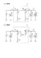
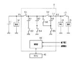
- FIG. 1 is an electric circuit diagram showing the power supply system in the first embodiment.
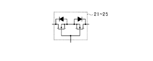
- FIG. 2 is a diagram showing a specific configuration of the switch.
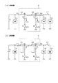
- 3A is a diagram showing a state in which lithium ion storage batteries are connected in parallel
- FIG. 3B is a diagram showing a state in which lithium ion storage batteries are connected in series
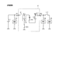
- 4A is a diagram showing a current flow during parallel charging
- FIG. 4B is a diagram showing a current flow during parallel discharging
- FIG. 5 is a diagram showing the flow of current during series discharge
- FIG. 1 is an electric circuit diagram showing the power supply system in the first embodiment.
- FIG. 2 is a diagram showing a specific configuration of the switch.
- 3A is a diagram showing a state in which lithium ion storage batteries are connected in parallel
- FIG. 3B is a diagram showing a state in which lithium ion storage batteries are connected in series
- 4A is a diagram showing a current flow during parallel charging
- FIG. 4B is a diagram showing
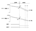
- FIG. 6 is a time chart showing transitions of SOC1 and SOC2 of each lithium ion storage battery at the time of parallel discharge and at the time of series discharge.
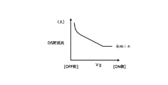
- FIG. 7 is a diagram illustrating the relationship between the gate voltage and the drain-source resistance.
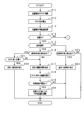
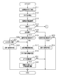
- FIG. 8 is a flowchart showing a processing procedure for controlling the connection state and charge / discharge current of the lithium ion storage battery
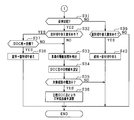
- FIG. 9 is a flowchart showing a processing procedure following FIG.
- FIG. 10 is a diagram illustrating the relationship between the SOC difference and the switch resistance value.
- FIG. 11 is an electric circuit diagram showing a power supply system in the second embodiment.
- FIG. 12 is a diagram showing a state in which lithium ion storage batteries are connected in series, FIG.
- FIG. 13 is a flowchart showing a processing procedure for controlling the connection state and charge / discharge current of the lithium ion storage battery in the second embodiment.
- FIG. 14 is a flowchart showing a processing procedure following FIG.
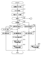
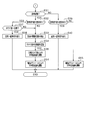
- FIG. 15 is a flowchart showing a processing procedure for controlling the connection state and charge / discharge current of the lithium ion storage battery in the third embodiment.
- FIG. 16 is a flowchart showing the processing procedure following FIG.
- FIG. 17 is a diagram illustrating the relationship between the terminal voltage difference ⁇ V and the switch resistance value.
- FIG. 18 is a diagram illustrating a relationship among a terminal voltage difference ⁇ V, a battery temperature, and a switch resistance value.
- an in-vehicle power supply device that supplies electric power to various devices of the vehicle in a vehicle that runs using an engine (internal combustion engine) as a drive source is embodied.
- the power supply system is a so-called dual power supply system including a first power storage device having a lead storage battery and a second power storage device having a plurality of lithium ion storage batteries as the power storage device. .
- the power supply system includes a lead storage battery 11 and two lithium ion storage batteries 12 and 13, and from each storage battery 11 to 13 to various electric loads 14 and 15 and a rotating electrical machine 16. Can be fed. Further, each of the storage batteries 11 to 13 can be charged by the rotating electrical machine 16.
- the lead storage battery 11 is a well-known general-purpose storage battery.
- the lithium ion storage batteries 12 and 13 are high-density storage batteries that have less power loss in charge and discharge and higher output density and energy density than the lead storage battery 11.
- the lithium ion storage batteries 12 and 13 may be storage batteries having higher energy efficiency during charging / discharging than the lead storage battery 11.
- the lithium ion storage batteries 12 and 13 are each configured as an assembled battery having a plurality of single cells.
- the rated voltages of the storage batteries 11 to 13 are the same, for example, 12V.
- the two lithium ion storage batteries 12 and 13 are housed in a housing case and configured as an integral battery unit U.
- the battery unit U has two output terminals P1 and P2, among which the lead storage battery 11 and the electric load 14 are connected to the output terminal P1, and the electric load 15 and the rotating electrical machine 16 are connected to the output terminal P2. Has been.
- the electrical load 14 connected to the output terminal P1 is a 12V system load driven based on 12V power supply from the lead storage battery 11 or the lithium ion storage batteries 12 and 13.
- the electric load 14 includes a constant voltage request load that is required to be constant or at least stable so that the voltage of the supplied power fluctuates within a predetermined range, and a general electric load other than the constant voltage request load. It is.
- the constant voltage required load is a load to be protected and is a load in which power supply failure is not allowed. Specific examples of the constant voltage required load include various ECUs such as a navigation device, an audio device, a meter device, and an engine ECU.
- the electric load 15 is a high-voltage load in which a large driving force is temporarily required, for example, when the vehicle is traveling, that is, a high power requirement may occur.
- a specific example is an electric steering device.
- the electric load 14 connected to the output terminal P1 corresponds to a low voltage electric load
- the electric load 15 and the rotating electrical machine 16 connected to the output terminal P2 correspond to a high voltage electric load.
- the rotating shaft of the rotating electrical machine 16 is drivingly connected to an engine output shaft (not shown) by a belt or the like.
- the rotating shaft of the rotating electrical machine 16 is rotated by the rotation of the engine output shaft, while the rotating shaft of the rotating electrical machine 16 is rotated.
- the rotating electrical machine 16 is an MG (Motor Generator), and has a power generation function for generating power (regenerative power generation) by rotation of the engine output shaft and the axle, and a power running function for applying rotational force to the engine output shaft.
- the rotating electrical machine 16 is configured to perform adjustment of the generated current during power generation and torque adjustment during powering driving by an inverter as a power conversion device provided integrally or separately.
- the engine is started and torque assist is performed by driving the rotating electrical machine 16.
- the rotating electrical machine 16 is an electric load in terms of adding power to the engine output shaft, and is a high power / high current load in comparison with the electric load 14.
- a switch 17 is provided between the electric load 15 and the rotating electrical machine 16, and the storage batteries 11 to 13 and the rotating electrical machine 16 and the electrical load 15 are electrically connected or disconnected by turning on or off the switch 17. It is like that.
- the two lithium ion storage batteries 12 and 13 can be switched between a parallel connection state and a serial connection state, which will be described in detail.
- switches 21 and 22 are provided in series on the electric path L1 between the output terminals P1 and P2.
- the electrical path L1 is also a part of the energization path where the electrical loads 14 and 15 and the rotating electrical machine 16 are connected to the lead storage battery 11 in the present system.
- the positive terminal (positive terminal) of the lithium ion storage battery 12 is connected to the first point N1 between the switches 21 and 22, and the positive terminal of the lithium ion storage battery 13 is connected to the second point N2 between the switch 22 and the output terminal P2. It is connected.
- switches 23 and 24 are provided between the negative terminals of the lithium ion storage batteries 12 and 13 and the ground, respectively.
- the first point N1 is connected to a third point N3 between the negative terminal of the lithium ion storage battery 13 and the switch 24, and a switch 25 is provided in the connection path.
- the switches 21 to 25 correspond to “switching units”.
- Each of the switches 21 to 25 is composed of a semiconductor switching element such as a MOSFET, IGBT, or bipolar transistor.
- each of the switches 21 to 25 is configured by a MOSFET, and the switches 21 to 25 are turned on and off according to application of a predetermined gate voltage.
- each of the switches 21 to 25 is configured to have two sets of MOSFETs, and the parasitic diodes of each set of MOSFETs are connected in series so that they are opposite to each other. Good.
- the parasitic diodes that are opposite to each other completely cut off the current that flows through the path in which the switches 21 to 25 are turned off.
- the configuration using semiconductor switching elements in each of the switches 21 to 25 may be arbitrary. For example, a configuration in which parasitic diodes of MOSFETs are not arranged in opposite directions may be used.
- FIG. 3A shows a state in which the lithium ion storage batteries 12 and 13 are connected in parallel
- FIG. 3B shows a state in which the lithium ion storage batteries 12 and 13 are connected in series.
- the energization path shown in FIG. 3A is a “parallel energization path”
- the energization path shown in FIG. 3B is a “series energization path”.
- the switch 17 is turned off in the parallel state and turned on as necessary in the series state.
- the switches 21 to 24 are turned on and the switch 25 is turned off.
- the lithium ion storage batteries 12 and 13 are in a parallel relationship.
- the output voltages of the output terminals P1 and P2 are both approximately 12V.
- the lead storage battery 11 and the lithium ion storage batteries 12 and 13 are connected in parallel to the electric load 14 on the P1 side, and the lead storage battery 11 and the lithium ion storage battery are connected in parallel to the rotating electrical machine 16 on the P2 side. 12 and 13 are connected.
- the electrical load 14 is connected to an intermediate position (first point N1) on the path connecting the positive electrodes of the lithium ion storage batteries 12 and 13 together.
- the switches 21, 23 and 25 are on and the switches 22 and 24 are off.
- the lithium ion storage batteries 12 and 13 are connected in series. It has become.
- the output voltage of the output terminal P1 is approximately 12V
- the output voltage of the output terminal P2 is approximately 24V.
- the lead storage battery 11 and the lithium ion storage battery 12 are connected in parallel to the electric load 14 on the P1 side.
- lithium ion storage batteries 12 and 13 are connected in series to the rotating electrical machine 16 on the P2 side.
- the rotating electrical machine 16 is connected to a position (second point N2) on the positive electrode side of the storage battery 13 on the high voltage side among the lithium ion storage batteries 12 and 13.
- the rotating electrical machine 16 is capable of 12V powering driving with a power supply voltage of 12V and 24V powering driving with a power supply voltage of 24V.
- the rotating electrical machine 16 When the lithium ion storage batteries 12 and 13 are connected in parallel, the rotating electrical machine 16 The rotary electric machine 16 is driven by 24V in a state where the battery is driven by 12V and the lithium ion batteries 12 and 13 are connected in series.
- the electric load 15 connected to the output terminal P2 is driven by 24V with the lithium ion storage batteries 12 and 13 connected in series.
- the battery unit U has a control unit 30 constituting battery control means.
- the control unit 30 switches on / off (opening / closing) the switches 21 to 25 in the battery unit U.
- the control unit 30 controls on / off of the switches 21 to 25 based on the running state of the vehicle and the storage states of the storage batteries 11 to 13.
- charging / discharging is implemented using the lead storage battery 11 and the lithium ion storage batteries 12 and 13 selectively.
- the charge / discharge control based on the storage state of each of the storage batteries 11 and 12 will be briefly described.
- each lithium ion storage battery 12 and 13 is each provided with the voltage sensor which detects a terminal voltage for every storage battery, and the current sensor which detects an energization current for every storage battery, respectively.
- the detection result of the sensor is input to the control unit 30.
- the control unit 30 sequentially acquires the terminal voltage detection values of the lead storage battery 11 and the lithium ion storage batteries 12 and 13 and sequentially acquires the energization currents of the lead storage battery 11 and the lithium ion storage batteries 12 and 13. And based on these acquired values, while calculating OCV (open circuit voltage: OpenageCircuit Voltage) and SOC (residual capacity: State Of Charge) of the lead storage battery 11 and the lithium ion storage batteries 12, 13, the OCV and SOC are calculated. The amount of charge and the amount of discharge to the lithium ion storage batteries 12 and 13 are controlled so as to be maintained within a predetermined use range.
- OCV open circuit voltage: OpenageCircuit Voltage
- SOC residual capacity: State Of Charge
- the lithium ion storage batteries 12 and 13 are basically brought into a parallel state so that the load drive request on the output terminal P2 side and the high voltage power generation for the rotating electrical machine 16 are performed.
- Each of the lithium ion storage batteries 12 and 13 can be switched to a series state in response to the above request.
- the control unit 30 temporarily switches the lithium ion storage batteries 12 and 13 from the parallel state to the serial state based on, for example, a drive request for the electric steering device (electric load 15) or a torque assist request by the rotating electrical machine 16. Implement control.
- the ECU 40 is connected to the control unit 30.
- the control unit 30 and the ECU 40 are connected by a communication network such as CAN and can communicate with each other, and various data stored in the control unit 30 and the ECU 40 can be shared with each other.
- the ECU 40 is an electronic control device having a function of performing idling stop control of the vehicle.
- the idling stop control automatically stops the engine when a predetermined automatic stop condition is satisfied, and restarts the engine when the predetermined restart condition is satisfied under the automatic stop state.
- the engine is started by the rotating electric machine 16 when the idling stop control is automatically restarted.
- FIG. 4A shows the current flow during parallel charging
- FIG. 4B shows the current flow during parallel discharging.
- a generated current is output from the rotating electrical machine 16, and the lead storage battery 11 and the lithium ion storage batteries 12 and 13 are charged and the electric load 14 is fed by the generated current.
- the switches 22 and 23 exist in the charging path of the lithium ion storage battery 12, and the charging current Iin 1 flows according to the path resistance including the switches 22 and 23.
- a switch 24 exists in the charging path to the lithium ion storage battery 13, and a charging current Iin 2 flows according to path resistance including the switch 24.
- the lithium ion storage battery 13 discharges with the electric load 15 and the rotating electrical machine 16 being discharged, whereas the lithium ion storage battery 12 has the electrical load 15 and the rotating electrical machine. In addition to 16, the electric load 14 is discharged. Therefore, the discharge current Iout1 of the lithium ion storage battery 12 becomes larger than the discharge current Iout2 of the lithium ion storage battery 13, thereby further increasing the SOC difference between the storage batteries 12 and 13.
- the SOC of each lithium ion storage battery 12 and 13 is varied, there is a disadvantage that the use area of each storage battery 12 and 13 cannot be fully utilized.
- the lithium ion storage battery 12 is connected in series to the electric load 14 that is a low-voltage load, and this corresponds to the “first power storage means”.
- the lithium ion storage battery 13 is connected in series to an electric load 15 or a rotating electrical machine 16 that is a high voltage load, and this corresponds to the “second power storage means”.
- the control unit 30 corresponds to a “capacity acquisition unit” and a “current control unit”.
- the solid line shows the SOC change when a desired amount of difference is intentionally given to SOC1 and SOC2 in the present embodiment, and the alternate long and short dash line equalizes SOC1 and SOC2 as a comparative example.
- the SOC change in the case of performing is shown.
- SOC1 is shown in the upper diagram and SOC2 is shown separately in the lower diagram.
- the difference between the discharge currents Iout1 and Iout2 of the lithium ion storage batteries 12 and 13 is caused by the difference in the switches on the discharge path, whereas in FIG.
- the difference between the discharge currents Iout1 and Iout2 of the lithium ion storage batteries 12 and 13 is caused by the difference between the discharge targets of the storage batteries 12 and 13, and the latter (during series discharge) is the discharge current. The difference is considered to increase.
- the resistance value in the energization path of the lithium ion storage battery 12 is made relatively larger than the resistance value in the energization path of the lithium ion storage battery 13.
- the discharge currents of the storage batteries 12 and 13 are controlled. More specifically, in FIG. 4B, the discharge current Iout1 of the lithium ion storage battery 12 is reduced by increasing the resistance value R1 of the switch 23 provided in the energization path of the lithium ion storage battery 12. In this case, by using the relationship between the gate voltage Vg and the drain-source resistance shown in FIG.
- the drain-source resistance by controlling the gate voltage Vg, the resistance value R1 of the switch 23, and consequently the lithium ion storage battery 12 side Change the path resistance value.
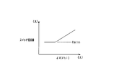
- the relationship in which the drain-source resistance increases by lowering the gate voltage Vg is defined with reference to the resistance value Rmin in the normally on state, and the switch resistance value (drain-source resistance) is higher than Rmin. It is variably set to the larger side.
- a predetermined difference is given to the SOC of each of the lithium ion storage batteries 12 and 13 as described above even in the parallel charge state.
- the resistance value in the energization path of the lithium ion storage battery 13 is made relatively larger than the resistance value in the energization path of the lithium ion storage battery 12 to control the charging current of each of the storage batteries 12 and 13. More specifically, in FIG. 4A, the charging current Iin2 of the lithium ion storage battery 13 is reduced by increasing the resistance value R2 of the switch 24 provided in the energization path of the lithium ion storage battery 13. In this case, by using the relationship of FIG. 7 and adjusting the drain-source resistance by controlling the gate voltage Vg, the resistance value R2 of the switch 24 and thus the path resistance value on the lithium ion storage battery 13 side are changed.
- FIGS. 8 and 9 are flowcharts showing a processing procedure for controlling the connection state and charging / discharging current of each lithium ion storage battery 12, 13, and this processing is repeatedly performed by the control unit 30 at a predetermined cycle.
- step S11 the SOC of each lithium ion storage battery 12 and 13 is acquired, and in the subsequent step S12, the SOC difference of each lithium ion storage battery 12 and 13 is calculated. Then, in step S13, the energization current value of each lithium ion storage battery 12 and 13 is acquired.
- step S14 it is determined whether or not the battery unit U is in the charged state. If the battery unit U is in the charged state, the process proceeds to step S15. If the battery unit U is not in the charged state, the process proceeds to step S31 in FIG.
- step S14 it is determined that the state of charge is in the charged state when the amount of power generation of the rotating electrical machine 16 is greater than the amount of power supplied to the load, and the state of discharge is determined when the amount of power supplied to the load is greater than the amount of power generated by the rotating electrical machine 16. It is determined. However, it may be determined whether or not the rotating electrical machine 16 is in a charged state depending on whether or not the rotating electrical machine 16 is in a power generating state.
- step S15 it is determined whether or not each of the lithium ion storage batteries 12 and 13 is in a parallel state. If the lithium ion storage batteries 12 and 13 are in a parallel state, the process proceeds to the subsequent step S16.
- step S16 it is determined whether or not a request for switching from the parallel state to the serial state has occurred for the lithium ion storage batteries 12 and 13. If no switching request is generated, the process proceeds to step S17, and the current control for each of the lithium ion storage batteries 12 and 13 is performed by the processes in steps S17 to S20.
- step S17 the drive state (power supply state) of each electric load 14, 15 is detected.
- step S18 the target value of the SOC difference in each lithium ion storage battery 12, 13 is determined based on the load drive state. Set. Specifically, in step S17, it is detected whether each of the electric loads 14 and 15 is in a drive-on state or a drive-off state. If the electric load 14 on the output terminal P1 side of the electric loads 14 and 15 is in the drive-on state, in step S18, it is anticipated that “Iout1> Iout2” will be obtained under the parallel discharge state, and each lithium ion storage battery The target value of the SOC difference is set so that the SOCs 12 and 13 are “SOC1> SOC2”.
- a target value of the SOC difference may be set based on the required power of the electric load 14. For example, the target value of the SOC difference is increased as the required power of the electric load 14 is increased.
- the target SOC of each of the lithium ion storage batteries 12 and 13 may be set based on the total required power by the electric loads 14 and 15, for example, the target SOC is increased as the total required power is larger.
- the target value of the SOC difference may be set based on which of the plurality of loads is in a driving state. For example, assuming that only one of the headlight and the wiper device as the electric load 14 is driven or both are driven, the target value of the SOC difference in the case of both driving is set as the SOC in the case of the one driving. It may be larger than the difference target value. However, in steps S17 and S18, it is also possible to set a predetermined value as a target value of the SOC difference satisfying “SOC1> SOC2”.
- step S19 when adjusting the path resistance value, it is determined whether or not the value of the energization current flowing through the target path on which the resistance value adjustment is performed is smaller than a predetermined value.
- a predetermined value it is determined whether or not an energization current value (Iin2 in FIG. 4A) flowing in the energization path of the storage battery 13 among the lithium ion storage batteries 12 and 13 is smaller than a predetermined value. If step S19 is YES, it will progress to subsequent step S20, and if step S19 is NO, this process will be complete
- step S20 the resistance value of the switch 24 to be adjusted is adjusted.
- gate voltage control is performed based on the target value of the SOC difference, and the switch 24 is changed to the side where the resistance value in the ON state is increased.
- the switch resistance value is set according to the SOC difference using the relationship of FIG. In FIG. 10, a relationship is defined in which the switch resistance value increases as the SOC difference increases.
- the switch resistance value is set according to the energization current value of the lithium ion storage battery 13. Specifically, considering that the energization current value is large, the energy loss in the resistance portion is increased. The larger the energization current value is, the smaller the switch resistance value is set.
- the control unit 30 adjusts the switch resistance value by digital analog control or PWM control (the same applies to step S36 described later).
- the path resistance value of the lithium ion storage battery 13 becomes larger than the path resistance value of the lithium ion storage battery 12, whereby the charging currents of the lithium ion storage batteries 12 and 13 are individually controlled. Will be.
- step S16 If it is determined in step S16 that a request for switching from the parallel state to the serial state has occurred, the process proceeds to step S21, and whether or not the SOC difference between the lithium ion storage batteries 12 and 13 matches the target value. judge. Specifically, it is determined whether or not the actual SOC difference is within a predetermined range determined based on the target value. The predetermined range is defined by an upper limit value and a lower limit value. If the SOC difference matches the target value, the process proceeds to step S22, and switching from the parallel state to the serial state is performed. If the SOC difference does not match the target value, the process proceeds to step S17, and the above-described resistance adjustment process is performed (steps S17 to S20).
- step S15 If it is determined in step S15 that the state is not the parallel state but the series state, the process proceeds to step S23 to determine whether or not a request for switching from the series state to the parallel state has occurred for the lithium ion batteries 12 and 13. . If a switching request is generated, the process proceeds to step S24, and switching from the serial state to the parallel state is performed. If no switching request is generated, the process is terminated as it is.
- step S14 determines whether the battery is in a discharged state instead of a charged state. If it is determined in step S31 in FIG. 9 whether each of the lithium ion storage batteries 12 and 13 is in a parallel state and is in a parallel state. The process proceeds to the subsequent step S32. In step S32, it is determined whether or not a request for switching from the parallel state to the serial state has occurred for the lithium ion storage batteries 12 and 13. If no switching request is generated, the process proceeds to step S33, and resistance value adjustment processing in the energization path of each lithium ion storage battery 12 and 13 is performed by the processing in steps S33 to S36.
- step S33 the drive state (power supply state) of each electric load 14, 15 is detected.
- step S34 the target value of the SOC difference in each lithium ion storage battery 12, 13 is determined based on the load drive state.
- Steps S33 and S34 are the same processes as steps S17 and S18 described above, and when the electric load 14 is in a drive-on state, the SOC of each lithium ion storage battery 12 and 13 is “SOC1> SOC2”.
- the target value of the SOC difference is set.
- the target value of the SOC difference may be set as a different value between parallel charging and parallel discharging.
- steps S33 and S34 it is also possible to set a predetermined value as a target value of the SOC difference satisfying “SOC1> SOC2”.
- step S35 when the path resistance value is adjusted, it is determined whether or not the value of the energization current flowing through the target path on which the resistance value adjustment is performed is smaller than a predetermined value.
- a predetermined value it is determined whether or not the energization current value (Iout1 in FIG. 4B) flowing in the energization path of the storage battery 12 among the lithium ion storage batteries 12 and 13 is smaller than a predetermined value. If step S35 is YES, it will progress to subsequent step S36, and if step S35 is NO, this process will be complete
- step S36 the resistance value of the switch 23 to be adjusted is adjusted.
- gate voltage control is performed based on the target value of the SOC difference, and the switch 23 is changed to the side where the resistance value in the ON state is increased.
- the switch resistance value may be set using the relationship shown in FIG. 10 as in step S20 described above.
- the path resistance value of the lithium ion storage battery 12 becomes larger than the path resistance value of the lithium ion storage battery 13, whereby the discharge currents of the lithium ion storage batteries 12 and 13 are individually controlled. Will be.
- step S32 when it is determined in step S32 that a request for switching from the parallel state to the serial state has occurred, the process proceeds to step S37, and whether or not the SOC difference between the lithium ion storage batteries 12 and 13 matches the target value. judge. Specifically, it is determined whether or not the actual SOC difference is within a predetermined range determined based on the target value. If the SOC difference matches the target value, the process proceeds to step S38, and switching from the parallel state to the serial state is performed. If the SOC difference does not match the target value, the process proceeds to step S33, and the above-described resistance adjustment process is performed (steps S33 to S36).
- step S31 when it is determined in step S31 that the state is not the parallel state but the series state, the process proceeds to step S39, and it is determined whether or not a request for switching from the serial state to the parallel state has occurred for the lithium ion storage batteries 12 and 13. . If a switching request is generated, the process proceeds to step S40, and switching from the serial state to the parallel state is performed. If no switching request is generated, the process is terminated as it is.
- each storage battery 12 when each lithium ion storage battery 12, 13 is in a parallel state, each storage battery 12 has a desired amount of difference in the SOC of each storage battery 12, 13 based on the SOC of each storage battery 12, 13.
- the charging / discharging current is controlled by adjusting the switch resistance value in the 13 energization paths.
- a desired amount of SOC difference is intentionally given in anticipation of switching to the serial state thereafter.
- the lithium ion storage battery 12 (low voltage load side power storage means) has a larger discharge current than the lithium ion storage battery 13 (high voltage load side power storage means), and the SOC can be reduced more quickly. Conceivable.
- the switch resistance value is adjusted so that the SOC1 of the lithium ion storage battery 12 is larger than the SOC2 of the lithium ion storage battery 13 in the parallel state, it is still in series with respect to each electric load. Even when electric power is supplied, it is possible to prevent the SOC difference between the lithium ion storage batteries 12 and 13 from being excessively widened.
- the lithium ion storage battery 12 since the SOC of the lithium ion storage battery 12 that is likely to be overdischarged is relatively increased, the lithium ion storage battery 12 is in an overdischarged state, that is, the SOC is near the lower limit of the use width, thereby the battery unit. The inconvenience that the discharge of U is limited is suppressed. Therefore, in each lithium ion storage battery 12, 13, it is possible to make maximum use from the SOC upper limit to the SOC lower limit, and it is possible to extend the actual use range of the SOC.
- the resistance value of the switch 23 in the energization path of the lithium ion storage battery 12 is relative to the resistance value of the switch 24 in the energization path of the lithium ion storage battery 13. Therefore, the discharge current of each lithium ion storage battery 12 and 13 is controlled.
- the discharge of the storage battery 13 on the high voltage load side among the lithium ion storage batteries 12 and 13 is preferentially discharged, so that the decrease in the SOC of the storage battery 12 on the low voltage load side can be reduced. . Thereby, an SOC difference can be given to each lithium ion storage battery 12, 13 as desired.
- the resistance value of the switch 24 in the energization path of the lithium ion storage battery 13 is set relatively to the resistance value of the switch 23 in the energization path of the lithium ion storage battery 12.
- the charging current of each lithium ion storage battery 12 and 13 is controlled to be large.
- the increase in SOC of the storage battery 13 on the high voltage load side can be reduced by preferentially charging the storage battery 12 on the low voltage load side among the lithium ion storage batteries 12 and 13. . Thereby, an SOC difference can be given to each lithium ion storage battery 12, 13 as desired.
- a target value of the SOC difference of each lithium ion storage battery 12 and 13 is set, and in the parallel state, the SOC difference of each lithium ion storage battery 12 and 13 is The switch resistance value is adjusted so as to be the target value. In this case, even if the required power of the electric load 14 changes, the SOC difference can be applied to the lithium ion storage batteries 12 and 13 as desired.
- the resistance value of the switches 23, 24 provided on the minus terminal side of each storage battery 12, 13 is changed to the larger side.
- the configuration is such that the resistance value is increased to the side of increasing the resistance value (minimum resistance value Rmin) in the full-on state of the switches 23 and 24. In this case, it can suppress that charging / discharging electric current becomes large too much, and can protect each lithium ion storage battery 12 and 13.
- FIG. considering that the switches 23 and 24 are constituted by semiconductor switching elements such as MOSFETs, resistance adjustment can be easily realized by controlling the gate voltage of the semiconductor switching elements.
- the resistance value of the switch whose resistance value is to be changed is set based on the charge / discharge current of each lithium ion storage battery 12, 13, taking into account the energy loss caused by increasing the resistance value
- the resistance value adjustment can be controlled. In this case, when the charge / discharge current of each lithium ion storage battery 12 and 13 is relatively large, the resistance value is decreased, and the resistance value is increased in accordance with the decrease of the charge / discharge current. Thereby, the energy loss due to the switch resistance can be reduced as much as possible.
- the resistance values of the switches 21 to 25 for switching the series and parallel of the storage batteries 12 and 13 are adjusted, and the charge / discharge current is controlled for each lithium ion storage battery 12 and 13. It was set as the structure to do. In this case, by utilizing the on-resistance generated in each of the switches 21 to 25, the charge / discharge current for each of the storage batteries 12 and 13 is controlled, so that each lithium ion storage battery can be used as desired without complicating the configuration. 12, 13 SOCs can be managed.
- the switches 21 to 25 are constituted by semiconductor switching elements, the charge / discharge current for each of the lithium ion storage batteries 12 and 13 can be easily adjusted by controlling the gate voltage of the MOSFET.
- each switch 21 to 25 a pair of MOSFETs was used, and a configuration in which the parasitic diodes of these MOSFETs were connected in series so as to be opposite to each other was adopted. As a result, when the switches 21 to 25 are turned off, the current flowing through the energization path can be suitably cut off.
- the gate voltage control is performed by digital analog control or PWM control for each of the switches 21 to 25 whose resistance value is to be adjusted. Thereby, the desired resistance value can be easily adjusted.
- PWM control theoretically, the loss due to the current becomes zero when the duty is off, so that a highly efficient system can be realized.
- the path resistance value is controlled by using the switch for series / parallel switching provided as the basic function of the battery unit U and the control unit 30 for performing the switching control, so that there is nothing to the basic unit configuration.
- a process for adjusting a desired resistance value can be realized without adding an element or the like.
- the lithium ion storage batteries 12 and 13 are allowed to shift from the parallel state to the serial state.
- the resistance value adjustment control in the parallel state is continuously performed, and the SOC difference is within the predetermined range. Transition from parallel state to serial state. Accordingly, it is possible to suppress the SOC difference from being excessively small or excessive, and to suppress the occurrence of inconvenience due to the SOC difference after the shift to the serial state.
- the second embodiment will be described focusing on the differences from the first embodiment described above.
- it is set as the structure which comprises three lithium ion storage batteries, and the series-parallel switching is possible about the three lithium ion storage batteries.
- the structure which comprises four or more lithium ion storage batteries is also possible.
- the battery unit U has three lithium ion storage batteries B1, B2, and B3, and a connection switching circuit is added with the addition of the lithium ion storage battery.
- the battery unit U has switches 51 to 56 constituted by semiconductor switching elements.
- the lithium ion storage batteries B1 to B3 can be switched between a parallel state and a series state by turning on and off the switches 51 to 56.
- FIG. 12 shows a state in which the lithium ion storage batteries B1 to B3 are connected in series in the power supply system of FIG.
- illustration of the switches 52 and 55 in the off state is omitted.
- the output voltage of the output terminal P1 is approximately 12V
- the output voltage of the output terminal P2 is approximately 24V.
- the lithium ion storage batteries B1 and B2 are connected in series to the electric load 14 that is a low voltage load, and this corresponds to the “first power storage means”. Further, the lithium ion storage battery B3 is connected to the electric load 15 and the rotating electrical machine 16 which are high voltage loads in series, and this corresponds to the “second power storage means”.
- the control unit 30 acquires the SOC of each of the lithium ion storage batteries B1 to B3, and when the storage batteries B1 to B3 are in parallel, the storage battery B1 and B2 side and the storage battery B3 side
- the resistance value of each switch is adjusted so that a predetermined difference occurs in the SOC, and the charge / discharge current is controlled for each of the storage batteries B1 to B3.
- a difference is intentionally given to the SOC of each of the storage batteries B1 to B3 in anticipation of switching from the parallel state to the serial state thereafter.
- the SOC difference is excessively expanded in each of the lithium ion batteries B1 to B3. It is suppressed.
- FIG. 13 and FIG. 14 are flowcharts showing a processing procedure for controlling the connection state and charging / discharging current of each lithium ion storage battery 12, 13, and this processing is repeatedly performed by the control unit 30 at a predetermined cycle. This process is performed in place of the processes shown in FIGS. 8 and 9 described above, and common processes are denoted by the same step numbers, and description thereof will be simplified as appropriate.
- step S51 it is determined whether or not all of the lithium ion storage batteries B1 to B3 are in a charged state. That is, it is determined whether or not the storage battery being charged and the storage battery being discharged are mixed due to mutual self-balance in each of the lithium ion storage batteries B1 to B3.
- step S51 it is preferable to determine whether or not each of the storage batteries B1 to B3 is in a charged state based on the direction of the energization current in each of the lithium ion storage batteries B1 to B3. If step S51 is YES, the process proceeds to the subsequent step S20. If step S51 is NO, the process is terminated.
- step S51 it is determined that a discharge current is flowing from one of the lithium ion storage batteries B1 to B3 to another storage battery in the power generation state of the rotating electrical machine 16. If step S51 is negative, that is, if it is determined that the discharge current is flowing in any of the storage batteries in the power generation state (charged state of the battery unit U), it is assumed that the battery is in the self-balance state, and this processing is continued. Is terminated. Thereby, the adjustment of the switch resistance value (step S20) is skipped.
- step S52 it is determined whether or not all of the lithium ion storage batteries B1 to B3 are in a discharged state. That is, it is determined whether or not the storage battery being charged and the storage battery being discharged are mixed due to mutual self-balance in each of the lithium ion storage batteries B1 to B3.
- step S52 it is preferable to determine whether or not each of the storage batteries B1 to B3 is in a discharged state based on the direction of the energization current in each of the lithium ion storage batteries B1 to B3. If step S52 is YES, the process proceeds to the subsequent step S36, and if step S52 is NO, the process ends.
- step S52 it is determined that the charging current is flowing from one of the storage batteries among the lithium ion storage batteries B1 to B3 in the non-power generation state of the rotating electrical machine 16. If step S52 is negative, that is, if it is determined that the charging current is flowing in any of the storage batteries in the non-power generation state (the discharge state of the battery unit U), it is determined that the battery is in the self-balance state. It ends as it is. Thereby, the adjustment of the switch resistance value (step S36) is skipped.
- each of the lithium ion storage batteries B1 to B3 when a discharge current is flowing through any one of the lithium ion storage batteries in a power generation state, that is, when a discharge current flows due to self-balance between the storage batteries, the discharge is Priority should be given. Further, in each of the lithium ion storage batteries B1 to B3, when a charging current is flowing through any one of the lithium ion storage batteries although not in a power generation state, that is, when a charging current flows due to self-balancing between the storage batteries, the charging is performed. Is preferred. In this regard, the switch resistance value is adjusted on the condition that all the lithium ion storage batteries B1 to B3 are determined to be in either the charged state or the discharged state. Thereby, it can suppress that the flow of the electric current by self-balancing is inhibited.
- the third embodiment will be described focusing on the differences from the first embodiment described above.
- the SOC difference is positively provided in each power storage unit of the battery unit U.
- a parameter having a correlation with the magnitude of the current flowing between the lithium ion storage batteries 12 and 13 is acquired, and current suppression control is appropriately performed based on the parameter.
- a storage state parameter indicating the state of each lithium ion storage battery 12, 13 is acquired as a parameter correlated with the current between each lithium ion storage battery 12, 13, and the switch 22 existing between the storage batteries 12, 13 in a parallel state.
- the switch resistance value is adjusted based on the storage state parameter with the switch 25 existing between the storage batteries 12 and 13 in the series state as an adjustment target.
- the storage state parameter for example, at least one of the terminal voltage, SOC, and charge / discharge current of each lithium ion storage battery 12, 13 is acquired.
- the temperatures of the lithium ion storage batteries 12 and 13 may be acquired.
- the control unit 30 exists at an intermediate position between the storage batteries 12 and 13 in the parallel energization path based on the storage state parameters of the lithium ion storage batteries 12 and 13 in order to suppress overcurrent.
- the resistance value of the switch 22 is adjusted to be increased.
- the control unit 30 acquires the difference ⁇ V between the terminal voltages of the lithium ion batteries 12 and 13 and performs feedback control based on the ⁇ V, thereby controlling the resistance value of the switch 22 to a desired value.
- the resistance value of the switch 22 is controlled by controlling the gate voltage of the switch 22. Thereby, the resistance value in the ON state of the switch 22 is increased, and accordingly, the current between the storage batteries is reduced. By this control, the current between the storage batteries is feedback-controlled to a desired value.
- each lithium ion storage battery 12 and 13 is used as the storage state parameter to determine whether or not an overcurrent flows, and each lithium ion storage battery 12 is subjected to the overcurrent flow. , 13 and the resistance value of the switch 22 can be controlled based on the charge / discharge current.
- the energization path shown in FIG. 3B is formed in the battery unit U, and if the power supply voltage composed of both lithium ion storage batteries 12 and 13 is large, the storage batteries 12 and 13 and the electrical load 15 or There is a concern that an overcurrent flows in the energization path to the rotating electrical machine 16. Actually, there is a concern that an overcurrent flows through a smoothing capacitor provided in the electric load 15 or the rotating electrical machine 16. Therefore, the control unit 30 is present at an intermediate position between the storage batteries 12 and 13 in the series energization path based on the storage state parameters of the lithium ion storage batteries 12 and 13 in order to suppress overcurrent. The switch 25 is adjusted so that the resistance value of the switch 25 is increased.
- the control unit 30 acquires the series power supply voltage (synthetic voltage Vhi) from the sum of the terminal voltages of the lithium ion storage batteries 12 and 13, and implements feedback control based on the Vhi, so that the resistance of the switch 25 Control the value to the desired value. More specifically, the resistance value of the switch 25 is controlled by controlling the gate voltage of the switch 25. Thereby, the resistance value in the ON state of the switch 25 is increased, and accordingly, the current between the storage batteries is reduced. By this control, the current between the storage batteries is feedback-controlled to a desired value.
- synthetic voltage Vhi synthetic voltage
- 15 and 16 are flowcharts showing a processing procedure for controlling the connection state and charging / discharging current of each lithium ion storage battery 12, 13, and this processing is repeatedly performed by the control unit 30 at a predetermined cycle. This process is performed in place of the processes shown in FIGS. 8 and 9 described above, and common processes are denoted by the same step numbers, and description thereof will be simplified as appropriate.
- step S61 after acquiring the SOC of each lithium ion storage battery 12 and 13 and calculating the SOC difference (steps S11 and S12), in step S61, the storage state parameter is acquired.
- the storage state parameter is acquired.
- at least one of charge / discharge current, terminal voltage, and SOC detected for each of the lithium ion storage batteries 12 and 13 is acquired as the storage state parameter.
- step S17 the driving state of each electrical load 14, 15 is reached. (Power supply state) is detected, and in the subsequent step S18, a target value of the SOC difference in each of the lithium ion storage batteries 12 and 13 is set based on the load drive state. At this time, if the electric load 14 on the output terminal P1 side is in the drive-on state, the SOC value of each lithium ion storage battery 12 and 13 is set to “SOC1> SOC2”, and the target value of the SOC difference is set.
- step S20 the resistance value of the switch 24 to be adjusted, that is, the switch 24 provided in the energization path on the lithium ion storage battery 13 side, is adjusted based on the target value of the SOC difference.
- step S62 the current flowing between the lithium ion storage batteries 12 and 13 is feedback-controlled to a desired value based on the storage state parameter of each lithium ion storage battery 12 and 13.
- the control unit 30 calculates the terminal voltage difference ⁇ V using the terminal voltages of the lithium ion batteries 12 and 13 as the storage state parameters.
- the adjustment resistance value of the switch 22 is determined based on the terminal voltage difference ⁇ V.
- a relationship is defined in which the adjustment resistance value of the switch 22 becomes larger as the terminal voltage difference ⁇ V is larger.
- the adjustment resistance value is set larger than the resistance value (minimum value Rmin) when the switch 22 is in the full-on state.
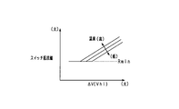
- the adjustment resistance value of the switch 22 may be determined using the relationship shown in FIG. In FIG. 18, the relationship between the terminal voltage difference ⁇ V of each lithium ion storage battery 12, 13, the battery temperature, and the adjustment resistance value of the switch 22 is defined. In this case, the adjustment resistance value of the switch 22 is set based on each parameter described above.
- the battery temperature may be at least one of the lithium ion storage batteries 12 and 13. What is necessary is just to use the average value as battery temperature, when acquiring the temperature of both the storage batteries 12 and 13. FIG.
- step S63 based on the storage state parameter of each lithium ion storage battery 12, 13
- the control unit 30 uses the terminal voltage of each of the lithium ion storage batteries 12 and 13 as the storage state parameter, and uses the combined voltage Vhi (that is, the output terminal P2) of the lithium ion storage batteries 12 and 13 in the series state. Voltage value).
- the adjustment resistance value of the switch 25 is determined based on the voltage Vhi. In FIG. 17, a relationship is defined such that the adjustment resistance value of the switch 25 becomes larger as the voltage Vhi is larger.
- the adjustment resistance value of the switch 25 may be determined using the relationship shown in FIG. 18 (where the horizontal axis is Vhi). In FIG. 18, the relationship among the voltage Vhi, the battery temperature, and the adjustment resistance value of the switch 25 is defined. In this case, the adjustment resistance value of the switch 25 is set based on the above parameters.
- step S33 in FIG. 15 is detected, and in a subsequent step S34, a target value of the SOC difference in each of the lithium ion storage batteries 12, 13 is set based on the load driving state.
- the SOC value of each lithium ion storage battery 12 and 13 is set to “SOC1> SOC2”, and the target value of the SOC difference is set.
- step S36 the resistance value of the switch 23 to be adjusted, that is, the switch 23 provided in the energization path on the lithium ion storage battery 12 side is adjusted based on the target value of the SOC difference.
- the current flowing between the lithium ion storage batteries 12 and 13 is feedback-controlled to a desired value based on the storage state parameter of each lithium ion storage battery 12 and 13.
- the control unit 30 determines the adjustment resistance value of the switch 22 based on the difference ⁇ V between the terminal voltages of the lithium ion storage batteries 12 and 13 and the battery temperature, using the relationship of FIG. 17 or FIG.
- step S65 based on the electrical storage state parameter of each lithium ion storage battery 12,13, The current flowing between the lithium ion batteries 12 and 13 is feedback-controlled to a desired value.
- the control unit 30 determines the adjustment resistance value of the switch 25 based on the combined voltage Vhi of the lithium ion storage batteries 12 and 13 and the battery temperature, using the relationship of FIG. 17 or FIG.
- the storage state parameter indicating the state of the plurality of lithium ion storage batteries 12 and 13 is acquired, and the storage state parameter exists between the storage batteries 12 and 13 in a parallel state or a series state based on the storage state parameter.
- the resistance values of the switches 22 and 25 were adjusted.
- the resistance value is adjusted with the switch 22 on the parallel energization path as the adjustment target based on the storage state parameter, so that the occurrence of overcurrent can be suitably suppressed.
- the storage state parameter at least one of the charge / discharge current, terminal voltage, and SOC of each lithium ion storage battery 12 and 13 is acquired, and the switch resistance value is adjusted based on the acquisition result.
- feedback control can be suitably realized according to the actual storage state of each of the lithium ion storage batteries 12 and 13.
- the temperature of each lithium ion storage battery 12 and 13 is acquired as a storage state parameter, and the switch resistance value is adjusted based on the acquisition result.
- the battery temperature is a parameter that can be acquired at any timing regardless of the series-parallel state (that is, the switch state), unlike the electrical parameters such as the charge / discharge current, the terminal voltage, and the SOC.
- the thirteen states can be suitably monitored.
- a configuration using a battery other than the lithium ion storage battery may be used as the plurality of power storage means.
- any of a configuration using a storage battery other than a lithium ion storage battery, a configuration using a storage battery and a capacitor, and a configuration using a plurality of capacitors may be used as the plurality of power storage means.
- the resistance value at the time of switching on the switch for series-parallel switching of a plurality of lithium ion batteries is adjusted, and thereby the charge / discharge current for each lithium ion battery is individually controlled. May be changed.
- another switch composed of a semiconductor switching element is provided in addition to the switch for series / parallel switching, and the on-resistance value of the other switch is adjusted, thereby charging and discharging each lithium ion storage battery. It is good also as a structure which controls an electric current separately.
- variable resistance portion In addition to using a semiconductor switching element as the variable resistance portion, it is also possible to use a variable resistor.
- the battery unit U it is good also as a structure which makes the maximum electrical storage amount of each lithium ion storage battery 12 and 13 differ.
- the rated voltage of the lithium ion storage battery 12 (first power storage means) is different from the rated voltage of the lithium ion storage battery 13 (second power storage means).
- first power storage means the rated voltage of the lithium ion storage battery 12
- second power storage means the rated voltage of the lithium ion storage battery 13
- the maximum storage amount that can be stored in the lithium ion storage battery 12 is the lithium ion storage battery 13. It is good also as a thing larger than the largest electrical storage amount which can be stored in.
- the maximum storage amount of the lithium ion storage battery 12 is set to be larger than the maximum storage amount of the lithium ion storage battery 13, it can be used even if the SOC1 of the lithium ion storage battery 12 is larger than the SOC2 of the lithium ion storage battery 13. It is possible to make the amount of power storage substantially equal. Therefore, an easy-to-use power supply system can be realized while giving an SOC difference between the lithium ion storage batteries 12 and 13.
Landscapes
- Engineering & Computer Science (AREA)
- Manufacturing & Machinery (AREA)
- Chemical & Material Sciences (AREA)
- Chemical Kinetics & Catalysis (AREA)
- Electrochemistry (AREA)
- General Chemical & Material Sciences (AREA)
- Power Engineering (AREA)
- Charge And Discharge Circuits For Batteries Or The Like (AREA)
- Secondary Cells (AREA)
Abstract
電源システムは、複数の蓄電手段(12,13)と、前記各蓄電手段に通じる電気経路に設けられた複数のスイッチ手段(21~25)を含み、前記複数の蓄電手段について並列状態と直列状態とを切り替える切替部と、を備える。前記複数の蓄電手段は、直列状態で低電圧負荷(14)に正極側が接続される第1蓄電手段(12)と、直列状態で高電圧負荷(15,16)に正極側が接続される第2蓄電手段(13)とを含む。電源制御装置(30)は、前記複数の蓄電手段の電気残容量を取得する容量取得部と、並列状態である場合に、前記容量取得部により取得した各蓄電手段の電気残容量に基づいて、前記第1蓄電手段の電気残容量と前記第2蓄電手段の電気残容量との差が所望量になるように、前記各蓄電手段に通じる電気経路に存在している抵抗可変部の抵抗値を調整して前記蓄電手段ごとに充放電電流を制御する電流制御部と、を備える。
Description
本出願は、2016年7月6日に出願された日本出願番号2016-134005号に基づくもので、ここにその記載内容を援用する。
本開示は、複数の蓄電手段を備える電源システムに適用される電源制御装置、及び電源システムに関するものである。
従来、複数の蓄電池を備える電源装置において、エンジン運転状態に応じて、複数の蓄電池を並列接続した状態と直列接続した状態とを切り替えるようにした技術が知られている(例えば特許文献1参照)。具体的には、エンジン自動始動システムにおいて、エンジン運転中は、接続切替手段としてのリレーにより各蓄電池を並列接続の状態にして、発電機により各蓄電池を充電する。また、エンジン自動停止後の再始動時には、リレーにより各蓄電池を直列接続の状態に切り替え、始動機への給電を実施する。そして上記構成により、エンジン始動を円滑にし、かつ蓄電池が劣化することを抑制することができるとしていた。
しかしながら、上記のように複数の蓄電池の並列接続と直列接続との切り替えを可能にするシステムでは、複数の蓄電池に通じる各通電経路上にそれぞれリレーやスイッチ等の接続切替手段が設けられていること、直列/並列状態で通電経路上のリレーやスイッチ等の個数に違いが生じることにより、各蓄電池で通電経路の抵抗値に違いが生じる。そのため、複数の蓄電池に流れる充放電電流に差違が生じ、結果として各蓄電池で電気残容量(SOC)にばらつきが生じる。そして、各蓄電池でSOCばらつきが生じると、充電時には高SOCの蓄電池により充電が制約される一方、放電時には低SOCの蓄電池により放電が制約されることになり、各蓄電池の使用領域を十分に活用することができないといった不都合を招来する。
本開示は、上記課題に鑑みてなされたものであり、その主たる目的は、各蓄電手段での容量ばらつきを抑制し、ひいては各蓄電手段において適正な充放電を行わせることができる電源制御装置、及び電源システムを提供することにある。
本開示の電源制御装置は、複数の蓄電手段と、前記各蓄電手段に通じる電気経路に設けられた複数のスイッチ手段を含み、前記複数の蓄電手段について互いに並列接続された並列状態と互いに直列接続された直列状態とを切り替える切替部と、を備え、前記複数の蓄電手段は、前記直列状態で低電圧系の低電圧負荷に正極側が接続される第1蓄電手段と、前記直列状態で高電圧系の高電圧負荷に正極側が接続される第2蓄電手段とを含んでいる電源システムに適用される。そして、電源制御装置は、前記複数の蓄電手段の電気残容量をそれぞれ取得する容量取得部と、前記複数の蓄電手段が並列状態である場合に、前記容量取得部により取得した各蓄電手段の電気残容量に基づいて、前記第1蓄電手段の電気残容量と前記第2蓄電手段の電気残容量との差が所望量になるように、前記各蓄電手段に通じる電気経路に存在している抵抗可変部の抵抗値を調整して前記蓄電手段ごとに充放電電流を制御する電流制御部と、を備える。
直並列の切り替えが可能な複数の蓄電手段を備え、そのうち第1蓄電手段は、直列状態で低電圧系の低電圧負荷に正極側が接続され、第2蓄電手段は、直列状態で高電圧系の高電圧負荷に正極側が接続されている電源システムでは、直列状態において、第1蓄電手段と第2蓄電手段とで放電電流が大小相違し、それに起因して電気残容量(SOC)の差が大きくなることが考えられる。
この点、上記構成では、複数の蓄電手段が並列状態である場合に、各蓄電手段の電気残容量に基づいて、第1蓄電手段の電気残容量と第2蓄電手段の電気残容量との差が所望量になるように、各蓄電手段に通じる電気経路に存在している抵抗可変部の抵抗値を調整して蓄電手段ごとに充放電電流を制御するようにした。この場合、各蓄電手段が並列接続された状態において、その後に各蓄電手段が直列状態に切り替えられることを見越して、第1蓄電手段と第2蓄電手段とで意図的に電気残容量に所望量の差が付与される。これにより、直列状態で低電圧系及び高電圧系の各電気負荷に対して電力供給が行われる際にも、各蓄電手段において電気残容量の差が過剰に拡がることを抑制できる。その結果、各蓄電手段が直並列で切り替える場合にあっても各蓄電手段の電気残容量を適正に管理することができる。
なお、複数の蓄電手段(例えばリチウムイオン蓄電池)の直並列の切り替えが行われる構成としては、直並列切り替え可能な2つ以上の蓄電手段を有する構成であればよく、例えば3つ以上の蓄電手段を備える電源システムにおいて、そのうち少なくとも2つの蓄電手段について直並列の切り替えが行われる構成も含まれる。
蓄電手段の電気残容量は、蓄電手段に蓄積可能な全電気容量のうち残存している電気量を示すものであってもよいし、蓄電手段において検出誤差や冗長使用領域、劣化用マージン等を除いた使用可能領域のうち残存している電気量を示すものであってもよい。
本開示についての上記目的およびその他の目的、特徴や利点は、添付の図面を参照しながら下記の詳細な記述により、より明確になる。その図面は、
図1は、第1実施形態における電源システムを示す電気回路図であり、
図2は、スイッチの具体的構成を示す図であり、
図3は、(a)は各リチウムイオン蓄電池を並列接続した状態を示す図、(b)は各リチウムイオン蓄電池を直列接続した状態を示す図であり、
図4は、(a)は並列充電時の電流の流れを示す図、(b)は並列放電時の電流の流れを示す図であり、
図5は、直列放電時の電流の流れを示す図であり、
図6は、並列放電時及び直列放電時における各リチウムイオン蓄電池のSOC1,SOC2の推移を示すタイムチャートであり、
図7は、ゲート電圧とドレインソース間抵抗との関係を示す図であり、
図8は、リチウムイオン蓄電池の接続状態と充放電電流とを制御する処理手順を示すフローチャートであり、
図9は、図8に続く処理手順を示すフローチャートであり、
図10は、SOC差とスイッチ抵抗値との関係を示す図であり、
図11は、第2実施形態における電源システムを示す電気回路図であり、
図12は、各リチウムイオン蓄電池を直列接続した状態を示す図であり、
図13は、第2実施形態においてリチウムイオン蓄電池の接続状態と充放電電流とを制御する処理手順を示すフローチャートであり、
図14は、図13に続く処理手順を示すフローチャートであり、
図15は、第3実施形態においてリチウムイオン蓄電池の接続状態と充放電電流とを制御する処理手順を示すフローチャートであり、
図16は、図15に続く処理手順を示すフローチャートであり、
図17は、端子電圧の差ΔVとスイッチ抵抗値との関係を示す図であり、
図18は、端子電圧の差ΔVと電池温度とスイッチ抵抗値との関係を示す図である。
(第1実施形態)
以下、本開示を具体化した実施形態を図面に基づいて説明する。本実施形態では、エンジン(内燃機関)を駆動源として走行する車両において当該車両の各種機器に電力を供給する車載電源装置を具体化するものとしている。また、本電源システムは、蓄電装置として、鉛蓄電池を有してなる第1蓄電装置と、複数のリチウムイオン蓄電池を有してなる第2蓄電装置とを備える、いわゆる2電源システムとなっている。
以下、本開示を具体化した実施形態を図面に基づいて説明する。本実施形態では、エンジン(内燃機関)を駆動源として走行する車両において当該車両の各種機器に電力を供給する車載電源装置を具体化するものとしている。また、本電源システムは、蓄電装置として、鉛蓄電池を有してなる第1蓄電装置と、複数のリチウムイオン蓄電池を有してなる第2蓄電装置とを備える、いわゆる2電源システムとなっている。
図1に示すように、本電源システムは、鉛蓄電池11と2つのリチウムイオン蓄電池12,13とを有しており、各蓄電池11~13からは各種の電気負荷14,15と回転電機16への給電が可能となっている。また、各蓄電池11~13に対しては回転電機16による充電が可能となっている。
鉛蓄電池11は周知の汎用蓄電池である。これに対し、リチウムイオン蓄電池12,13は、鉛蓄電池11に比べて、充放電における電力損失が少なく、出力密度、及びエネルギ密度の高い高密度蓄電池である。リチウムイオン蓄電池12,13は、鉛蓄電池11に比べて充放電時のエネルギ効率が高い蓄電池であるとよい。また、リチウムイオン蓄電池12,13は、それぞれ複数の単電池を有してなる組電池として構成されている。これら各蓄電池11~13の定格電圧はいずれも同じであり、例えば12Vである。
図示による詳細な説明は割愛するが、2つのリチウムイオン蓄電池12,13は、収容ケースに収容されて一体の電池ユニットUとして構成されている。電池ユニットUは、2つの出力端子P1,P2を有しており、このうち出力端子P1に鉛蓄電池11と電気負荷14とが接続され、出力端子P2に電気負荷15と回転電機16とが接続されている。
出力端子P1に接続される電気負荷14は、鉛蓄電池11又はリチウムイオン蓄電池12,13からの12V給電に基づいて駆動される12V系負荷である。その電気負荷14には、供給電力の電圧が一定又は少なくとも所定範囲内で変動するよう安定であることが要求される定電圧要求負荷と、定電圧要求負荷以外の一般的な電気負荷とが含まれている。定電圧要求負荷は被保護負荷であって、電源失陥が許容されない負荷である。定電圧要求負荷の具体例としては、ナビゲーション装置やオーディオ装置、メータ装置、エンジンECU等の各種ECUが挙げられる。この場合、供給電力の電圧変動が抑えられることで、上記各装置において不要なリセット等が生じることが抑制され、安定動作が実現可能となっている。また、一般的な電気負荷の具体例としては、ヘッドライト等のランプ類やワイパ装置、電動ポンプが挙げられる。
また、電気負荷15は、例えば車両走行時において一時的に大きな駆動力が要求される、すなわち高電力要求が生じることがある高電圧系の負荷である。具体例としては、電動ステアリング装置が挙げられる。なお、出力端子P1に接続される電気負荷14が低電圧電気負荷に相当し、出力端子P2に接続される電気負荷15及び回転電機16が高電圧電気負荷に相当する。
回転電機16の回転軸は、図示しないエンジン出力軸に対してベルト等により駆動連結されており、エンジン出力軸の回転によって回転電機16の回転軸が回転する一方、回転電機16の回転軸の回転によってエンジン出力軸が回転する。回転電機16は、MG(Motor Generator)であり、エンジン出力軸や車軸の回転により発電(回生発電)を行う発電機能と、エンジン出力軸に回転力を付与する力行機能とを備えている。回転電機16は、一体又は別体に設けられた電力変換装置としてのインバータにより、発電時の発電電流の調整や力行駆動時のトルク調整が行われるものとなっている。回転電機16の駆動により、エンジンの始動やトルクアシストが行われる。回転電機16は、エンジン出力軸に対して動力を付加する観点から言えば電気負荷であり、しかも電気負荷14との比較で言えば高電力/高電流負荷である。
電気負荷15と回転電機16との間にはスイッチ17が設けられており、そのスイッチ17のオンオフにより、各蓄電池11~13や回転電機16と電気負荷15とが電気的に接続又は遮断されるようになっている。
次に、電池ユニットUにおける電気的構成を説明する。本実施形態では、2つのリチウムイオン蓄電池12,13について並列接続の状態と直列接続の状態との切り替えを可能としており、その点について詳しく説明する。
電池ユニットUでは、出力端子P1,P2の間の電気経路L1にスイッチ21,22が直列に設けられている。なお、電気経路L1は、本システムにおいて鉛蓄電池11に対して電気負荷14,15や回転電機16が接続される通電経路の一部でもある。そして、スイッチ21,22の間の第1点N1にリチウムイオン蓄電池12の+端子(正極端子)が接続され、スイッチ22と出力端子P2との第2点N2にリチウムイオン蓄電池13の+端子が接続されている。また、各リチウムイオン蓄電池12,13の-端子(負極端子)とグランドとの間には、それぞれスイッチ23,24が設けられている。さらに、第1点N1は、リチウムイオン蓄電池13の-端子とスイッチ24との間の第3点N3に接続されており、その接続経路にスイッチ25が設けられている。スイッチ21~25が「切替部」に相当する。
上記の各スイッチ21~25は、MOSFET、IGBT、バイポーラトランジスタ等の半導体スイッチング素子により構成されている。本実施形態では、各スイッチ21~25がMOSFETにより構成されており、所定のゲート電圧の印加に応じてスイッチ21~25のオンオフが切り替えられる。
なお、図2に示すように、各スイッチ21~25をそれぞれ2つ一組のMOSFETを有する構成とし、各一組のMOSFETの寄生ダイオードが互いに逆向きになるように直列に接続されているとよい。この互いに逆向きの寄生ダイオードによって、各スイッチ21~25をオフ状態とした場合にそのスイッチが設けられた経路に流れる電流が完全に遮断される。ただし、各スイッチ21~25において半導体スイッチング素子を用いた構成は任意でよく、例えばMOSFETの寄生ダイオードが互いに逆向きに配置されていない構成であってもよい。
そして、これら各スイッチ21~25のオンオフを適宜切り替えることにより、各リチウムイオン蓄電池12,13が並列接続された状態と、各リチウムイオン蓄電池12,13が直列接続された状態とが切り替えられるようになっている。
図3において(a)には、各リチウムイオン蓄電池12,13を並列接続した状態を示し、(b)には各リチウムイオン蓄電池12,13を直列接続した状態を示している。図3では、理解を容易にするために、スイッチ21~25についてオン状態のスイッチのみを示し、オフ状態のスイッチの図示を省略している。図3(a)に示された通電経路が「並列通電経路」であり、図3(b)に示された通電経路が「直列通電経路」である。なお、スイッチ17は、並列状態ではオフされ、直列状態では必要に応じてオンされるようになっている。
図3(a)では、各スイッチ21~25のうちスイッチ21~24がオン、スイッチ25がオフされており、かかる状態では、リチウムイオン蓄電池12,13が並列の関係となっている。この場合、出力端子P1,P2の出力電圧はいずれも概ね12Vとなっている。並列接続状態では、P1側の電気負荷14に対して並列に鉛蓄電池11及びリチウムイオン蓄電池12,13が接続されるとともに、P2側の回転電機16に対して並列に鉛蓄電池11及びリチウムイオン蓄電池12,13が接続されている。並列接続状態では、各リチウムイオン蓄電池12,13の正極どうしを接続する経路上の中間位置(第1点N1)に電気負荷14が接続されるようになっている。
また、図3(b)では、各スイッチ21~25のうちスイッチ21,23,25がオン、スイッチ22,24がオフされており、かかる状態では、リチウムイオン蓄電池12,13が直列の関係となっている。この場合、出力端子P1の出力電圧は概ね12V、出力端子P2の出力電圧は概ね24Vとなっている。直列接続状態では、P1側の電気負荷14に対して並列に鉛蓄電池11及びリチウムイオン蓄電池12が接続されている。また、P2側の回転電機16に対して直列にリチウムイオン蓄電池12,13が接続されている。直列接続状態では、各リチウムイオン蓄電池12,13のうち高電圧側の蓄電池13の正極側の位置(第2点N2)に回転電機16が接続されるようになっている。
回転電機16は、電源電圧を12Vとする12V力行駆動と、電源電圧を24Vとする24V力行駆動とが可能になっており、リチウムイオン蓄電池12,13が並列接続された状態では回転電機16が12V駆動され、リチウムイオン蓄電池12,13が直列接続された状態では回転電機16が24V駆動される。出力端子P2に接続された電気負荷15は、リチウムイオン蓄電池12,13が直列接続された状態で24V駆動される。
また、図1において、電池ユニットUは、電池制御手段を構成する制御部30を有している。制御部30は、電池ユニットU内の各スイッチ21~25のオンオフ(開閉)の切り替えを実施する。この場合、制御部30は、車両の走行状態や各蓄電池11~13の蓄電状態に基づいて、各スイッチ21~25のオンオフを制御する。これにより、鉛蓄電池11とリチウムイオン蓄電池12,13とを選択的に用いて充放電が実施される。各蓄電池11,12の蓄電状態に基づく充放電制御について簡単に説明する。なお、図示は省略するが、各リチウムイオン蓄電池12,13には、蓄電池ごとに端子電圧を検出する電圧センサと、蓄電池ごとに通電電流を検出する電流センサとがそれぞれ設けられており、それら各センサの検出結果は制御部30に入力される。
制御部30は、鉛蓄電池11及びリチウムイオン蓄電池12,13の端子電圧の検出値を逐次取得するとともに、鉛蓄電池11、リチウムイオン蓄電池12,13の通電電流を逐次取得する。そして、これらの取得値に基づいて、鉛蓄電池11、リチウムイオン蓄電池12,13のOCV(開放電圧:Open Circuit Voltage)やSOC(残存容量:State Of Charge)を算出するとともに、そのOCVやSOCが所定の使用範囲内に保持されるようにリチウムイオン蓄電池12,13への充電量及び放電量を制御する。
また、電池ユニットUでは、車両へのメイン電源の投入後において、基本的には各リチウムイオン蓄電池12,13が並列状態とされ、出力端子P2側における負荷駆動要求や回転電機16に対する高電圧発電の要求に応じて、各リチウムイオン蓄電池12,13が直列状態に切り替えられるようになっている。この場合、制御部30は、例えば電動ステアリング装置(電気負荷15)の駆動要求や、回転電機16によるトルクアシスト要求に基づいて、リチウムイオン蓄電池12,13を一時的に並列状態から直列状態に切り替える制御を実施する。
制御部30にはECU40が接続されている。制御部30及びECU40は、CAN等の通信ネットワークにより接続されて相互に通信可能となっており、制御部30及びECU40に記憶される各種データが互いに共有できるものとなっている。ECU40は、車両のアイドリングストップ制御を実施する機能を有する電子制御装置である。アイドリングストップ制御は、周知のとおり所定の自動停止条件の成立によりエンジンを自動停止させ、かつその自動停止状態下で所定の再始動条件の成立によりエンジンを再始動させるものである。車両においては、アイドリングストップ制御の自動再始動時に回転電機16によりエンジンが始動されるようになっている。
次に、リチウムイオン蓄電池12,13が並列接続された状態で回転電機16からの充電が行われる並列充電時と、リチウムイオン蓄電池12,13が並列接続された状態で電気負荷14への放電が行われる並列放電時とについて説明する。図4(a)には、並列充電時の電流の流れを示し、(b)には、並列放電時の電流の流れを示している。
図4(a)の並列充電時には、回転電機16から発電電流が出力され、その発電電流により鉛蓄電池11及び各リチウムイオン蓄電池12,13の充電や、電気負荷14への給電が行われる。このとき、電池ユニットUにおいて、リチウムイオン蓄電池12の充電経路にはスイッチ22,23が存在しており、そのスイッチ22,23を含む経路抵抗に応じて充電電流Iin1が流れる。また、リチウムイオン蓄電池13への充電経路にはスイッチ24が存在しており、そのスイッチ24を含む経路抵抗に応じて充電電流Iin2が流れる。充電電流Iin1,Iin2を比べると、Iin1≠Iin2となり、特に経路抵抗の違いから「Iin1<Iin2」になることが想定される。
また、図4(b)の並列放電時には、各リチウムイオン蓄電池12,13から電気負荷14への給電が行われる。このとき、リチウムイオン蓄電池12から電気負荷14への放電経路にはスイッチ21,23が存在しており、そのスイッチ21,23を含む経路抵抗に応じて放電電流Iout1が流れる。また、リチウムイオン蓄電池13から電気負荷14への放電経路にはスイッチ21,22,24が存在しており、そのスイッチ21,22,24を含む経路抵抗に応じて放電電流Iout2が流れる。放電電流Iout1,Iout2を比べると、Iout1≠Iout2となり、特に経路抵抗の違いから「Iout1>Iout2」になることが想定される。
上記のとおり各リチウムイオン蓄電池12,13の並列状態下では、それら各蓄電池12,13に流れる電流の大きさが相違する。そのため、各リチウムイオン蓄電池12,13においてSOC(電気容量)にばらつきが生じることが懸念される。この点についてさらに補足する。上記図4(a)の並列充電状態では、経路抵抗の違いから「Iin1<Iin2」になる一方、上記図4(b)の並列放電状態では、経路抵抗の違いから「Iout1>Iout2」になり、こうした電流の差からリチウムイオン蓄電池13の方がリチウムイオン蓄電池12よりも高SOCになることが想定されるが、その状態から直列接続状態(図3(b)参照)に移行すると、各蓄電池12,13のSOCの差がより大きくなると考えられる。
つまり、直列放電状態では、図5に示すように、リチウムイオン蓄電池13は、電気負荷15や回転電機16を放電対象として放電を行うのに対し、リチウムイオン蓄電池12は、電気負荷15や回転電機16に加え、電気負荷14を放電対象として放電を行う。ゆえにリチウムイオン蓄電池12の放電電流Iout1が、リチウムイオン蓄電池13の放電電流Iout2よりも大きくなり、これにより各蓄電池12,13のSOC差がさらに大きくなる。各リチウムイオン蓄電池12,13でSOCのばらつきが生じると、それら各蓄電池12,13の使用領域を十分に活用することができないといった不都合を招来する。
なお本実施形態では、リチウムイオン蓄電池12は、直列状態で低電圧負荷である電気負荷14に正極側が接続されており、これが「第1蓄電手段」に相当する。また、リチウムイオン蓄電池13は、直列状態で高電圧負荷である電気負荷15や回転電機16に正極側が接続されており、これが「第2蓄電手段」に相当する。
そこで本実施形態では、各リチウムイオン蓄電池12,13のSOCをそれぞれ取得するとともに、各蓄電池12,13が並列状態である場合に、各蓄電池12,13のSOCに所定の差が生じるように、各スイッチの抵抗値を調整して蓄電池12,13ごとに充放電電流を制御するようにしている。この場合、各リチウムイオン蓄電池12,13が並列接続された状態において、その後に並列状態から直列状態に切り替えられることを見越して、各蓄電池12,13のSOCに意図的に所望量の差が付与される。これにより、直列状態で低電圧負荷(12V系負荷)と高電圧負荷(24V系負荷)とに対して電力供給が行われる際にも、各リチウムイオン蓄電池12,13においてSOC差が過剰に拡がることが抑制される。なお、制御部30が「容量取得部」、「電流制御部」に相当する。
以下に、リチウムイオン蓄電池12,13の並列放電時と直列放電時とにおける各蓄電池12,13の電流制御について説明する。ここでは、図6を用い、並列放電状態(図4(b))から直列放電状態(図5)に移行する場合における各リチウムイオン蓄電池12,13のSOC変化について具体的に説明する。なお、図6において、SOC1,SOC2は、それぞれリチウムイオン蓄電池12,13のSOCを示し、抵抗R1,R2は、それぞれスイッチ23,24の抵抗値を示している。また、SOC1,SOC2の推移において、実線は、本実施形態においてSOC1,SOC2に意図的に所望量の差を付与する場合のSOC変化を示し、一点鎖線は、比較例としてSOC1,SOC2を均一化する場合のSOC変化を示している。SOC1は上図で、SOC2は下図でそれぞれ別々に示されている。
図6では、タイミングt1までの期間において並列放電が行われ、タイミングt1以降においては直列放電が行われる。ここで、並列放電時において各リチウムイオン蓄電池12,13のSOCを均一化する場合には、一点鎖線で示すように、タイミングt1でSOC1,SOC2が共に「A」となっている。そして、タイミングt1で並列状態から直列状態に切り替えられた後には、上述したように、各蓄電池12,13の放電対象の差から「Iout1>Iout2」になり、それによりSOC1,SOC2で減少変化に傾きが相違する。したがって、リチウムイオン蓄電池12においてリチウムイオン蓄電池13よりも早期にSOCが下限値に達してしまう(図のt2)。
これに対して、本実施形態では、並列放電時において各リチウムイオン蓄電池12,13のSOCに「SOC1>SOC2」となるように差を付与することとしている。そのため、SOC1,SOC2が実線で示すように推移し、タイミングt1では、SOC1,SOC2がそれぞれB1,B2となっている(B1>B2)。そして、タイミングt1で並列状態から直列状態に切り替えられた後には、各蓄電池12,13の放電対象の差から「Iout1>Iout2」になっていても、リチウムイオン蓄電池12のSOC1がリチウムイオン蓄電池13のSOC2よりも早期に下限値に達することを抑制できる(図のt3)。
ちなみに、図4(b)の並列放電時において、各リチウムイオン蓄電池12,13の放電電流Iout1,Iout2の差は、放電経路上のスイッチの差に起因するものであるのに対し、図5の直列放電時において、各リチウムイオン蓄電池12,13の放電電流Iout1,Iout2の差は、各蓄電池12,13の放電対象の差に起因するものであり、後者(直列放電時)の方が放電電流の差が大きくなると考えられる。
並列放電時に各リチウムイオン蓄電池12,13のSOCに差を付与する構成として、リチウムイオン蓄電池12の通電経路における抵抗値を、リチウムイオン蓄電池13の通電経路における抵抗値よりも相対的に大きくして、各蓄電池12,13の放電電流を制御する。より詳しくは、図4(b)において、リチウムイオン蓄電池12の通電経路に設けられたスイッチ23の抵抗値R1を増加させることにより、リチウムイオン蓄電池12の放電電流Iout1を小さくする。この場合、図7に示すゲート電圧Vgとドレインソース間抵抗との関係を用い、ゲート電圧Vgの制御によりドレインソース間抵抗を調整することで、スイッチ23の抵抗値R1、ひいてはリチウムイオン蓄電池12側の経路抵抗値を変更する。図7では、通常オン状態の抵抗値Rminを基準に、ゲート電圧Vgを低下させることでドレインソース間抵抗が増加する関係が定められており、スイッチ抵抗値(ドレインソース間抵抗)がRminよりも大きくする側に可変設定される。
スイッチ23の抵抗値R1を大きくすることにより、リチウムイオン蓄電池12に流れる放電電流Iout1が低減され、「SOC1>SOC2」となることが促される。これにより、並列状態から直列状態に切り替えられた後にリチウムイオン蓄電池12のSOC1が下限値に達するのを遅らせることができ、電池ユニットUでの放電が早期に制限されるといった不都合が抑制される。
本実施形態では、並列充電状態においても、上記同様、各リチウムイオン蓄電池12,13のSOCに所定の差を付与することとしている。この場合、リチウムイオン蓄電池13の通電経路における抵抗値を、リチウムイオン蓄電池12の通電経路における抵抗値よりも相対的に大きくして、各蓄電池12,13の充電電流を制御する。より詳しくは、図4(a)において、リチウムイオン蓄電池13の通電経路に設けられたスイッチ24の抵抗値R2を増加させることにより、リチウムイオン蓄電池13の充電電流Iin2を小さくする。この場合、図7の関係を用い、ゲート電圧Vgの制御によりドレインソース間抵抗を調整することで、スイッチ24の抵抗値R2、ひいてはリチウムイオン蓄電池13側の経路抵抗値を変更する。
スイッチ24の抵抗値R2を大きくすることにより、リチウムイオン蓄電池13に流れる充電電流Iin2が低減され、「SOC1>SOC2」となることが促される。これにより、各負荷に対する電力供給が行われる状況下において、充電状態から放電状態への切り替え後にリチウムイオン蓄電池12のSOC1が下限値に達するのを遅らせることができ、やはり電池ユニットUでの放電が早期に制限されるといった不都合が抑制される。
図8及び図9は、各リチウムイオン蓄電池12,13の接続状態と充放電電流とを制御する処理手順を示すフローチャートであり、本処理は制御部30により所定周期で繰り返し実施される。
図8において、ステップS11では、各リチウムイオン蓄電池12,13のSOCをそれぞれ取得し、続くステップS12では、各リチウムイオン蓄電池12,13のSOC差を算出する。その後、ステップS13では、各リチウムイオン蓄電池12,13の通電電流値を取得する。ステップS14では、電池ユニットUが充電状態であるか否かを判定し、充電状態であればステップS15に進み、充電状態でなく放電状態であれば図9のステップS31に進む。なお、ステップS14では、負荷給電量よりも回転電機16の発電量が多い場合に充電状態であると判定され、負荷給電量の方が回転電機16の発電量よりも多い場合に放電状態であると判定される。ただし、回転電機16が発電状態にあるか否かにより、充電状態であるか否かを判定してもよい。
ステップS15では、各リチウムイオン蓄電池12,13が並列状態であるか否かを判定し、並列状態である場合に後続のステップS16に進む。ステップS16では、リチウムイオン蓄電池12,13について並列状態から直列状態への切り替え要求が生じたか否かを判定する。そして、切り替え要求が生じていなければ、ステップS17に進み、ステップS17~S20の各処理により、リチウムイオン蓄電池12,13ごとの通電電流の制御を実施する。
詳しくは、ステップS17では、各電気負荷14,15の駆動状態(給電状態)を検出し、続くステップS18では、負荷駆動状態に基づいて、各リチウムイオン蓄電池12,13におけるSOC差の目標値を設定する。具体的には、ステップS17では、各電気負荷14,15が駆動オンの状態、駆動オフの状態のいずれであるかを検出する。そして、電気負荷14,15のうち出力端子P1側の電気負荷14が駆動オンの状態にあれば、ステップS18では、並列放電状態下で「Iout1>Iout2」になることを見越し、各リチウムイオン蓄電池12,13のSOCが「SOC1>SOC2」となるようにして、SOC差の目標値を設定する。このとき、電気負荷14の要求電力に基づいて、SOC差の目標値を設定するとよい。例えば、電気負荷14の要求電力が大きいほど、SOC差の目標値を大きくする。またこのとき、各電気負荷14,15による総要求電力に基づいて、各リチウムイオン蓄電池12,13の目標SOCを設定するとよく、例えば総要求電力が大きいほど目標SOCを大きくする。
なお、各電気負荷14,15がそれぞれ複数の負荷を含むものであれば、その複数の負荷のうちいずれが駆動状態になっているかに基づいて、SOC差の目標値を設定するとよい。例えば、電気負荷14としてのヘッドライトとワイパ装置のうち一方のみが駆動される場合と両方が駆動される場合と想定すると、両方駆動の場合のSOC差の目標値を、一方駆動の場合のSOC差目標値よりも大きくするとよい。ただし、ステップS17,S18において、「SOC1>SOC2」となるSOC差の目標値として、予め定めた所定値を設定することも可能である。
続くステップS19では、経路抵抗値の調整に際し、抵抗値調整を実施する対象経路に流れる通電電流値が所定値よりも小さいか否かを判定する。ここでは、リチウムイオン蓄電池12,13のうち蓄電池13の通電経路に流れる通電電流値(図4(a)のIin2)が所定値よりも小さいか否かを判定する。ステップS19がYESであれば後続のステップS20に進み、ステップS19がNOであればそのまま本処理を終了する。
ステップS20では、調整対象であるスイッチ24について抵抗値の調整を実施する。このとき、SOC差の目標値に基づいてゲート電圧制御を実施し、スイッチ24についてオン状態での抵抗値を大きくする側に変更する。例えば、図10の関係を用い、SOC差に応じてスイッチ抵抗値を設定する。図10では、SOC差が大きいほどスイッチ抵抗値を大きくする関係が定められている。また、図10によれば、リチウムイオン蓄電池13の通電電流値に応じてスイッチ抵抗値が設定されるようになっている。具体的には、通電電流値が大きいと抵抗部でのエネルギロスが大きくなることを加味し、通電電流値が大きいほど、スイッチ抵抗値が小さい値に設定されるようになっている。これにより、SOC差に応じてスイッチ抵抗値がRminよりも大きい値とされる場合にあっても、通電電流値が大きければ、その分、抵抗値が減補正されることとなる。なお、スイッチ抵抗値には上限値が定められているとよい。制御部30は、デジタルアナログ制御又はPWM制御によりスイッチ抵抗値を調整する(後述のステップS36も同様)。
ステップS20におけるスイッチ24の抵抗値調整により、リチウムイオン蓄電池13の経路抵抗値が、リチウムイオン蓄電池12の経路抵抗値よりも大きくなり、これにより各リチウムイオン蓄電池12,13の充電電流が個別に制御されることとなる。
また、ステップS16において並列状態から直列状態への切り替え要求が生じたと判定された場合には、ステップS21に進み、各リチウムイオン蓄電池12,13のSOC差が目標値に一致しているか否かを判定する。具体的には、実際のSOC差が、目標値を基準にして定めた所定範囲に入っているか否かを判定する。所定範囲は、上限値と下限値とにより規定されている。そして、SOC差が目標値に一致していれば、ステップS22に進み、並列状態から直列状態への切り替えを実施する。また、SOC差が目標値に一致していなければ、ステップS17に進み、上述した抵抗調整処理を実施する(ステップS17~S20)。
また、ステップS15で並列状態でなく直列状態であると判定された場合には、ステップS23に進み、リチウムイオン蓄電池12,13について直列状態から並列状態への切り替え要求が生じたか否かを判定する。そして、切り替え要求が生じていれば、ステップS24に進み、直列状態から並列状態への切り替えを実施する。また、切り替え要求が生じていなければそのまま本処理を終了する。
一方、ステップS14で充電状態でなく放電状態であると判定された場合、図9のステップS31では、各リチウムイオン蓄電池12,13が並列状態であるか否かを判定し、並列状態である場合に後続のステップS32に進む。ステップS32では、リチウムイオン蓄電池12,13について並列状態から直列状態への切り替え要求が生じたか否かを判定する。そして、切り替え要求が生じていなければ、ステップS33に進み、ステップS33~S36の各処理により、各リチウムイオン蓄電池12,13の通電経路における抵抗値の調整処理を実施する。
詳しくは、ステップS33では、各電気負荷14,15の駆動状態(給電状態)を検出し、続くステップS34では、負荷駆動状態に基づいて、各リチウムイオン蓄電池12,13におけるSOC差の目標値を設定する。ステップS33,S34は、上述のステップS17,S18と同様の処理であり、電気負荷14が駆動オンの状態にある場合に、各リチウムイオン蓄電池12,13のSOCが「SOC1>SOC2」となるようにして、SOC差の目標値を設定する。ただし、並列充電時と並列放電時とでSOC差の目標値を異なる値として設定してもよい。また、ステップS33,S34において、「SOC1>SOC2」となるSOC差の目標値として、予め定めた所定値を設定することも可能である。
続くステップS35では、経路抵抗値の調整に際し、抵抗値調整を実施する対象経路に流れる通電電流値が所定値よりも小さいか否かを判定する。ここでは、リチウムイオン蓄電池12,13のうち蓄電池12の通電経路に流れる通電電流値(図4(b)のIout1)が所定値よりも小さいか否かを判定する。ステップS35がYESであれば後続のステップS36に進み、ステップS35がNOであればそのまま本処理を終了する。
ステップS36では、調整対象であるスイッチ23について抵抗値の調整を実施する。このとき、SOC差の目標値に基づいてゲート電圧制御を実施し、スイッチ23についてオン状態での抵抗値を大きくする側に変更する。スイッチ抵抗値の設定は、上述のステップS20と同様に、図10の関係を用いて行われるとよい。
ステップS36におけるスイッチ23の抵抗値調整により、リチウムイオン蓄電池12の経路抵抗値が、リチウムイオン蓄電池13の経路抵抗値よりも大きくなり、これにより各リチウムイオン蓄電池12,13の放電電流が個別に制御されることとなる。
また、ステップS32において並列状態から直列状態への切り替え要求が生じたと判定された場合には、ステップS37に進み、各リチウムイオン蓄電池12,13のSOC差が目標値に一致しているか否かを判定する。具体的には、実際のSOC差が、目標値を基準にして定めた所定範囲に入っているか否かを判定する。そして、SOC差が目標値に一致していれば、ステップS38に進み、並列状態から直列状態への切り替えを実施する。また、SOC差が目標値に一致していなければ、ステップS33に進み、上述した抵抗調整処理を実施する(ステップS33~S36)。
また、ステップS31で並列状態でなく直列状態であると判定された場合には、ステップS39に進み、リチウムイオン蓄電池12,13について直列状態から並列状態への切り替え要求が生じたか否かを判定する。そして、切り替え要求が生じていれば、ステップS40に進み、直列状態から並列状態への切り替えを実施する。また、切り替え要求が生じていなければそのまま本処理を終了する。
以上詳述した本実施形態によれば、以下の優れた効果が得られる。
上記構成では、各リチウムイオン蓄電池12,13が並列状態である場合に、各蓄電池12,13のSOCに基づいて、各蓄電池12,13におけるSOCに所望量の差が生じるように、各蓄電池12,13の通電経路においてスイッチ抵抗値を調整して充放電電流を制御するようにした。この場合、並列状態において、その後に直列状態に切り替えられることを見越して、意図的に所望量のSOC差が付与される。これにより、直列状態で低電圧系及び高電圧系の各電気負荷14~16に対して電力供給が行われる際にも、各リチウムイオン蓄電池12,13においてSOC差が過剰に拡がることを抑制できる。その結果、各リチウムイオン蓄電池12,13が直並列で切り替える場合にあっても各蓄電池12,13のSOCを適正に管理することができる。
直列状態では、リチウムイオン蓄電池12(低電圧負荷側の蓄電手段)の方が、リチウムイオン蓄電池13(高電圧負荷側の蓄電手段)よりも放電電流が大きくなり、SOCの減りが早くなることが考えられる。この点、並列状態である場合に、リチウムイオン蓄電池12のSOC1がリチウムイオン蓄電池13のSOC2よりも大きくなるように、スイッチ抵抗値を調整する構成にしたため、やはり直列状態で各電気負荷に対して電力供給が行われる際にも、各リチウムイオン蓄電池12,13においてSOCの差が過剰に拡がることを抑制できる。
また、過放電状態になりやすい方のリチウムイオン蓄電池12についてSOCを相対的に大きくするようにしたため、そのリチウムイオン蓄電池12が過放電状態、すなわちSOCが使用幅の下限付近となり、それにより電池ユニットUの放電が制限されるといった不都合が抑制される。したがって、各リチウムイオン蓄電池12,13においてSOC上限からSOC下限までを最大限利用することが可能となり、SOCの実使用範囲の拡張を実現できる。
並列状態であり、かつ低電圧負荷への電力供給が行われる場合に、リチウムイオン蓄電池12の通電経路におけるスイッチ23の抵抗値を、リチウムイオン蓄電池13の通電経路におけるスイッチ24の抵抗値よりも相対的に大きくして、各リチウムイオン蓄電池12,13の放電電流を制御する構成とした。この場合、並列状態において、各リチウムイオン蓄電池12,13のうち高電圧負荷側の蓄電池13で放電を優先的に行わせることで、低電圧負荷側の蓄電池12のSOC低下を少なくすることができる。これにより、各リチウムイオン蓄電池12,13についてSOC差を所望のとおりに付与できる。
並列状態であり、かつ回転電機16の発電が行われる場合に、リチウムイオン蓄電池13の通電経路におけるスイッチ24の抵抗値を、リチウムイオン蓄電池12の通電経路におけるスイッチ23の抵抗値よりも相対的に大きくして、各リチウムイオン蓄電池12,13の充電電流を制御する構成とした。この場合、並列状態において、各リチウムイオン蓄電池12,13のうち低電圧負荷側の蓄電池12で充電を優先的に行わせることで、高電圧負荷側の蓄電池13のSOC増加を少なくすることができる。これにより、各リチウムイオン蓄電池12,13についてSOC差を所望のとおりに付与できる。
低電圧負荷である電気負荷14の駆動状態に基づいて、各リチウムイオン蓄電池12,13のSOC差の目標値を設定し、並列状態である場合に、各リチウムイオン蓄電池12,13のSOC差が目標値になるように、スイッチ抵抗値を調整する構成とした。この場合、電気負荷14の要求電力が変化しても、各リチウムイオン蓄電池12,13についてSOC差を所望のとおりに付与できる。
各リチウムイオン蓄電池12,13に通じる通電経路の経路抵抗値を変更する場合に、それら各蓄電池12,13の-端子側に設けられたスイッチ23,24の抵抗値を、大きくする側に変更する構成とした。つまり、各スイッチ23,24のフルオン状態の抵抗値(最小抵抗値Rmin)に対して抵抗値を大きくする側に変更する構成とした。この場合、充放電電流が過剰に大きくなることを抑制でき、各リチウムイオン蓄電池12,13の保護を図ることができる。また、スイッチ23,24をMOSFET等の半導体スイッチング素子により構成することを考えると、その半導体スイッチング素子のゲート電圧制御により容易に抵抗調整を実現できる。
各リチウムイオン蓄電池12,13の充放電電流に基づいて、抵抗値変更の対象となるスイッチの抵抗値を設定する構成としたため、抵抗値を大きくすることに起因して生じるエネルギロスを加味して、抵抗値調整の制御を実施できる。この場合、各リチウムイオン蓄電池12,13の充放電電流が比較的大きい場合には抵抗値を小さくしておき、充放電電流の減少に応じて抵抗値を大きくする。これにより、スイッチ抵抗によるエネルギロス分を極力低減できる。
各リチウムイオン蓄電池12,13が並列状態である場合に、各蓄電池12,13の直並列切り替え用のスイッチ21~25の抵抗値を調整し、リチウムイオン蓄電池12,13ごとに充放電電流を制御する構成とした。この場合、各スイッチ21~25でオン抵抗が生じることを利用して、蓄電池12,13ごとの充放電電流を制御することにより、構成の煩雑化を伴うことなく、所望のとおり各リチウムイオン蓄電池12,13のSOCを管理することができる。
スイッチ21~25を半導体スイッチング素子により構成したため、MOSFETのゲート電圧制御等により、リチウムイオン蓄電池12,13ごとの充放電電流の調整を簡易に実施できる。
スイッチ21~25として半導体スイッチング素子を用いたことにより、接点切替式のスイッチ(いわゆるメカスイッチ)を用いる場合に比べて、動作信頼性の高いシステムを構築できる。また、半導体スイッチング素子では、メカスイッチに比べて抵抗値を小さくすることができるため、通電経路での損失を低減することができる。
各スイッチ21~25として、2つ一組のMOSFETを用い、それら各MOSFETの寄生ダイオードが互いに逆向きになるように直列に接続される構成を採用した。これにより、各スイッチ21~25をオフする際において通電経路に流れる電流を好適に遮断することができる。
抵抗値調整対象の各スイッチ21~25についてデジタルアナログ制御又はPWM制御によりゲート電圧制御を実施する構成とした。これにより、所望とする抵抗値の調整を容易に実施することができる。PWM制御では、理論的にはデューティオフの時は電流による損失がゼロとなるため、高効率のシステムを実現できる。
また、電池ユニットUの基本機能として具備されている直並列切り替え用のスイッチと、その切り替え制御を行う制御部30とを用いて経路抵抗値の制御を行うことで、ユニット基本構成に対して何ら素子等の追加を行うこと無く、所望の抵抗値の調整処理を実現できる。
各リチウムイオン蓄電池12,13におけるSOC差が所定範囲に入っていると判定された場合に、各リチウムイオン蓄電池12,13を並列状態から直列状態に移行させることを許可する構成とした。この場合、各リチウムイオン蓄電池12,13におけるSOC差が所定範囲内に入っていない状態では、並列状態での抵抗値調整の制御が継続的に実施され、SOC差が所定範囲に入った状態で並列状態から直列状態に移行される。したがって、SOC差が過小又は過大になることが抑制され、直列状態への移行後において、SOC差に起因する不都合の発生を抑制できる。
(第2実施形態)
以下に、第2実施形態について上述の第1実施形態と相違点を中心に説明する。本実施形態では、3つのリチウムイオン蓄電池を具備する構成としており、その3つのリチウムイオン蓄電池について直並列の切り替えが可能となっている。なお、4つ以上のリチウムイオン蓄電池を具備する構成も可能である。
以下に、第2実施形態について上述の第1実施形態と相違点を中心に説明する。本実施形態では、3つのリチウムイオン蓄電池を具備する構成としており、その3つのリチウムイオン蓄電池について直並列の切り替えが可能となっている。なお、4つ以上のリチウムイオン蓄電池を具備する構成も可能である。
図11では、図1との相違点として、電池ユニットUは、3つのリチウムイオン蓄電池B1,B2,B3を有しており、リチウムイオン蓄電池の追加に伴い接続切り替えの回路が追加されている。電池ユニットUは、半導体スイッチング素子により構成されるスイッチ51~56を有している。各スイッチ51~56のオンオフにより、各リチウムイオン蓄電池B1~B3の並列状態と直列状態とが切り替え可能となっている。
図12は、図11の電源システムにおいて、各リチウムイオン蓄電池B1~B3を直列接続した状態を示している。なお図12では、オフ状態のスイッチ52,55の図示を省略している。直列状態では、出力端子P1の出力電圧は概ね12V、出力端子P2の出力電圧は概ね24Vとなっている。
本実施形態の電池ユニットUにおいては、リチウムイオン蓄電池B1,B2が、直列状態で低電圧負荷である電気負荷14に正極側が接続されており、これが「第1蓄電手段」に相当する。また、リチウムイオン蓄電池B3が、直列状態で高電圧負荷である電気負荷15や回転電機16に正極側が接続されており、これが「第2蓄電手段」に相当する。
そして本実施形態において、制御部30は、各リチウムイオン蓄電池B1~B3のSOCをそれぞれ取得するとともに、各蓄電池B1~B3が並列状態である場合に、蓄電池B1,B2の側と蓄電池B3の側とでSOCに所定の差が生じるように、各スイッチの抵抗値を調整して蓄電池B1~B3ごとに充放電電流を制御する。この場合、各リチウムイオン蓄電池B1~B3が並列接続された状態において、その後に並列状態から直列状態に切り替えられることを見越して、各蓄電池B1~B3のSOCに意図的に差が付与される。これにより、直列状態で低電圧負荷(12V系負荷)と高電圧負荷(24V系負荷)とに対して電力供給が行われる際にも、各リチウムイオン蓄電池B1~B3においてSOC差が過剰に拡がることが抑制される。
ちなみに、常に並列状態にあるリチウムイオン蓄電池B1,B2について、それら各蓄電池B1,B2のSOCを均等化させる処理を実施することも可能である。この場合、各リチウムイオン蓄電池B1,B2の放電時において、スイッチ53,54のうち低SOC側の蓄電池のスイッチについて抵抗値を大きくして放電電流を制限するとよい。
図13及び図14は、各リチウムイオン蓄電池12,13の接続状態と充放電電流とを制御する処理手順を示すフローチャートであり、本処理は制御部30により所定周期で繰り返し実施される。本処理は、上述した図8及び図9の処理に置き換えて実施されるものであり、共通の処理については同じステップ番号を付して説明を適宜簡略する。
図13では、図8及び図9の処理との相違点として、充電中であり、並列状態であり、かつ直列切り替え要求が生じていない場合(ステップS14,S15がYES、S16がNOの場合)に、ステップS51を実施する。ステップS51では、リチウムイオン蓄電池B1~B3の全てが充電状態になっているか否かを判定する。すなわち、各リチウムイオン蓄電池B1~B3での相互のセルフバランスにより充電中の蓄電池と放電中の蓄電池とが混在している状況にあるか否かを判定する。このとき、各リチウムイオン蓄電池B1~B3において通電電流の向きに基づいて、各蓄電池B1~B3が充電状態か否かを判定するとよい。ステップS51がYESであれば後続のステップS20に進み、ステップS51がNOであればそのまま本処理を終了する。
なお、ステップS51は、回転電機16の発電状態で、リチウムイオン蓄電池B1~B3のうちいずれかの蓄電池に他の蓄電池から放電電流が流れていることを判定するものである。ステップS51が否定される場合、すなわち発電状態(電池ユニットUの充電状態)なのにいずれかの蓄電池で放電電流が流れていると判定される場合には、セルフバランス状態にあるとして、本処理がそのまま終了される。これにより、スイッチ抵抗値の調整(ステップS20)が読み飛ばされる。
一方、図14では、図8及び図9の処理との相違点として、放電中であり、並列状態であり、かつ直列切り替え要求が生じていない場合(ステップS14がNO、S31がYES、S32がNOの場合)に、ステップS52を実施する。ステップS52では、リチウムイオン蓄電池B1~B3の全てが放電状態になっているか否かを判定する。すなわち、各リチウムイオン蓄電池B1~B3での相互のセルフバランスにより充電中の蓄電池と放電中の蓄電池とが混在している状況にあるか否かを判定する。このとき、各リチウムイオン蓄電池B1~B3において通電電流の向きに基づいて、各蓄電池B1~B3が放電状態か否かを判定するとよい。ステップS52がYESであれば後続のステップS36に進み、ステップS52がNOであればそのまま本処理を終了する。
なお、ステップS52は、回転電機16の非発電状態で、リチウムイオン蓄電池B1~B3のうちいずれかの蓄電池に他の蓄電池から充電電流が流れていることを判定するものである。ステップS52が否定される場合、すなわち非発電状態(電池ユニットUの放電状態)なのにいずれかの蓄電池で充電電流が流れていると判定される場合には、セルフバランス状態にあるとして、本処理がそのまま終了される。これにより、スイッチ抵抗値の調整(ステップS36)が読み飛ばされる。
各リチウムイオン蓄電池B1~B3において、発電状態であるのにいずれかのリチウムイオン蓄電池に放電電流が流れている場合、すなわち蓄電池間のセルフバランスにより放電電流が流れている場合には、その放電が優先されることが望ましい。また、各リチウムイオン蓄電池B1~B3において、発電状態でないのにいずれかのリチウムイオン蓄電池に充電電流が流れている場合、すなわち蓄電池間のセルフバランスにより充電電流が流れている場合には、その充電が優先されることが望ましい。この点、各リチウムイオン蓄電池B1~B3の全てが充電状態及び放電状態のうちいずれであると判定されたことを条件に、スイッチ抵抗値の調整を実施する構成とした。これにより、セルフバランスによる電流の流れが阻害されることを抑制できる。
発電状態においてセルフバランスにより放電電流が流れている場合に、その放電中のリチウムイオン蓄電池について経路抵抗値を大きくしない(すなわち小さいままにする)ことにより、セルフバランスによる放電を促すことができ、SOCばらつきを解消する上で好適となる。また、非発電状態においてセルフバランスにより充電電流が流れている場合に、その充電中のリチウムイオン蓄電池について経路抵抗値を大きくしない(すなわち小さいままにする)ことにより、セルフバランスによる充電を促すことができ、SOCばらつきを解消する上で好適となる。
(第3実施形態)
次に、第3実施形態について上述の第1実施形態と相違点を中心に説明する。本実施形態では、図1のシステムを用いた事例を説明する。上記実施形態では、電池ユニットUの各蓄電手段において積極的にSOC差を設けることとしているが、反面、SOC差が過剰に大きいと、蓄電手段間における容量自己調整による過電流の発生が懸念される。容量自己調整電流は、リチウムイオン蓄電池12,13間のSOC差と経路抵抗値とに応じて流れる電流であり、例えば「I=蓄電池間の出力電圧差×経路抵抗値」として定義される。この場合、蓄電池間において大きな電流が流れ、通電経路上のスイッチや蓄電池に悪影響が及ぶことが懸念される。
次に、第3実施形態について上述の第1実施形態と相違点を中心に説明する。本実施形態では、図1のシステムを用いた事例を説明する。上記実施形態では、電池ユニットUの各蓄電手段において積極的にSOC差を設けることとしているが、反面、SOC差が過剰に大きいと、蓄電手段間における容量自己調整による過電流の発生が懸念される。容量自己調整電流は、リチウムイオン蓄電池12,13間のSOC差と経路抵抗値とに応じて流れる電流であり、例えば「I=蓄電池間の出力電圧差×経路抵抗値」として定義される。この場合、蓄電池間において大きな電流が流れ、通電経路上のスイッチや蓄電池に悪影響が及ぶことが懸念される。
そこで本実施形態では、各リチウムイオン蓄電池12,13間で流れる電流の大きさに相関を持つパラメータを取得し、そのパラメータに基づいて、電流抑制の制御を適宜実施することとしている。ここでは、各リチウムイオン蓄電池12,13間の電流に相関するパラメータとして、各リチウムイオン蓄電池12,13の状態を示す蓄電状態パラメータを取得し、並列状態で蓄電池12,13間に存在するスイッチ22、又は直列状態で蓄電池12,13間に存在するスイッチ25を調整対象として、蓄電状態パラメータに基づいてスイッチ抵抗値を調整する。
蓄電状態パラメータとしては、例えば各リチウムイオン蓄電池12,13の端子電圧、SOC、充放電電流の少なくともいずれかが取得される。またこれに加えて、各リチウムイオン蓄電池12,13の温度が取得されるとよい。
制御部30により実施される並列状態での抵抗値制御と、直列状態での抵抗値制御とについて説明する。
並列状態では、電池ユニットUにおいて図3(a)に示す通電経路が形成されており、各リチウムイオン蓄電池12,13にSOC差が生じている状況下では、蓄電池12,13間に過電流が流れることが懸念される。そこで、制御部30は、過電流の抑制を図るべく、各リチウムイオン蓄電池12,13の蓄電状態パラメータに基づいて、並列状態の通電経路で各蓄電池12,13の間の中間位置に存在しているスイッチ22の抵抗値を大きくする側に調整する。このとき、制御部30は、各リチウムイオン蓄電池12,13の端子電圧の差ΔVを取得し、そのΔVに基づいてフィードバック制御を実施することで、スイッチ22の抵抗値を所望の値に制御する。より具体的には、スイッチ22のゲート電圧制御を実施することにより、スイッチ22の抵抗値を制御する。これにより、スイッチ22についてオン状態での抵抗値が大きくなり、それに伴い蓄電池間の電流が低減される。本制御により、蓄電池間の電流が所望の値にフィードバック制御される。
なお、蓄電状態パラメータとして、各リチウムイオン蓄電池12,13のSOCや充放電電流を用いて、過電流が流れる状況か否かを判定するとともに、過電流が流れる状況下において、各リチウムイオン蓄電池12,13のSOCや充放電電流に基づいてスイッチ22の抵抗値を制御することも可能である。
また、直列状態では、電池ユニットUにおいて図3(b)に示す通電経路が形成されており、両リチウムイオン蓄電池12,13よりなる電源電圧が大きいと、これら蓄電池12,13と電気負荷15又は回転電機16との間の通電経路で過電流が流れることが懸念される。実際には、電気負荷15や回転電機16に設けられた平滑コンデンサを通じて過電流が流れることが懸念される。そこで、制御部30は、過電流の抑制を図るべく、各リチウムイオン蓄電池12,13の蓄電状態パラメータに基づいて、直列状態の通電経路で各蓄電池12,13の間の中間位置に存在しているスイッチ25の抵抗値を大きくする側に調整する。このとき、制御部30は、各リチウムイオン蓄電池12,13の端子電圧の和により直列電源電圧(合成電圧Vhi)を取得し、そのVhiに基づいてフィードバック制御を実施することで、スイッチ25の抵抗値を所望の値に制御する。より具体的には、スイッチ25のゲート電圧制御を実施することにより、スイッチ25の抵抗値を制御する。これにより、スイッチ25についてオン状態での抵抗値が大きくなり、それに伴い蓄電池間の電流が低減される。本制御により、蓄電池間の電流が所望の値にフィードバック制御される。
図15及び図16は、各リチウムイオン蓄電池12,13の接続状態と充放電電流とを制御する処理手順を示すフローチャートであり、本処理は制御部30により所定周期で繰り返し実施される。本処理は、上述した図8及び図9の処理に置き換えて実施されるものであり、共通の処理については同じステップ番号を付して説明を適宜簡略する。
図15において、各リチウムイオン蓄電池12,13のSOCの取得、SOC差の算出(ステップS11,S12)を実施した後、ステップS61では、蓄電状態パラメータを取得する。本実施形態では、蓄電状態パラメータとして、リチウムイオン蓄電池12,13ごとに検出された充放電電流、端子電圧、SOCの少なくともいずれかを取得する。
その後、充電中であり、並列状態であり、かつ直列切り替え要求が生じていない場合(ステップS14,S15がYES、S16がNOの場合)に、ステップS17では、各電気負荷14,15の駆動状態(給電状態)を検出し、続くステップS18では、負荷駆動状態に基づいて、各リチウムイオン蓄電池12,13におけるSOC差の目標値を設定する。このとき、出力端子P1側の電気負荷14が駆動オンの状態にあれば、各リチウムイオン蓄電池12,13のSOCが「SOC1>SOC2」となるようにして、SOC差の目標値を設定する。
その後、ステップS20では、調整対象であるスイッチ24、すなわちリチウムイオン蓄電池13側の通電経路に設けられたスイッチ24について、SOC差の目標値に基づいて抵抗値の調整を実施する。
続くステップS62では、各リチウムイオン蓄電池12,13の蓄電状態パラメータに基づいて、リチウムイオン蓄電池12,13間を流れる電流を所望の値にフィードバック制御する。具体的には、制御部30は、蓄電状態パラメータとしての各リチウムイオン蓄電池12,13の端子電圧を用いて、その端子電圧の差ΔVを算出する。そして、図17の関係を用い、端子電圧の差ΔVに基づいてスイッチ22の調整抵抗値を決定する。図17では、端子電圧の差ΔVが大きいほど、スイッチ22の調整抵抗値が大きい値となる関係が定められている。調整抵抗値は、スイッチ22のフルオン状態での抵抗値(最小値Rmin)に対して大きい値が設定される。
図18の関係を用いて、スイッチ22の調整抵抗値を決定するようにしてもよい。図18では、各リチウムイオン蓄電池12,13の端子電圧の差ΔVと、電池温度と、スイッチ22の調整抵抗値との関係が定められている。この場合、上記の各パラメータに基づいて、スイッチ22の調整抵抗値が設定される。なお、電池温度は、リチウムイオン蓄電池12,13の少なくともいずれかの温度であればよい。両蓄電池12,13の温度を取得する場合には、その平均値を電池温度として用いればよい。
また、直列充電状態にあり、かつ並列切り替え要求が生じていない場合(ステップS14がYES、S15,S23がNOの場合)に、ステップS63では、各リチウムイオン蓄電池12,13の蓄電状態パラメータに基づいて、リチウムイオン蓄電池12,13間を流れる電流を所望の値にフィードバック制御する。具体的には、制御部30は、蓄電状態パラメータとしての各リチウムイオン蓄電池12,13の端子電圧を用いて、直列状態にあるリチウムイオン蓄電池12,13の合成電圧Vhi(すなわち、出力端子P2の電圧値)を算出する。そして、図17の関係(ただし横軸はVhi)を用い、電圧Vhiに基づいてスイッチ25の調整抵抗値を決定する。図17では、電圧Vhiが大きいほど、スイッチ25の調整抵抗値が大きい値となる関係が定められている。
図18の関係(ただし横軸はVhi)を用いて、スイッチ25の調整抵抗値を決定するようにしてもよい。図18では、電圧Vhiと、電池温度と、スイッチ25の調整抵抗値との関係が定められている。この場合、上記の各パラメータに基づいて、スイッチ25の調整抵抗値が設定される。
一方、放電中であり、並列状態であり、かつ直列切り替え要求が生じていない場合(ステップS14がNO、S31がYES、S32がNOの場合)に、図16のステップS33では、各電気負荷14,15の駆動状態(給電状態)を検出し、続くステップS34では、負荷駆動状態に基づいて、各リチウムイオン蓄電池12,13におけるSOC差の目標値を設定する。このとき、出力端子P1側の電気負荷14が駆動オンの状態にあれば、各リチウムイオン蓄電池12,13のSOCが「SOC1>SOC2」となるようにして、SOC差の目標値を設定する。
その後、ステップS36では、調整対象であるスイッチ23、すなわちリチウムイオン蓄電池12側の通電経路に設けられたスイッチ23について、SOC差の目標値に基づいて抵抗値の調整を実施する。
続くステップS64では、各リチウムイオン蓄電池12,13の蓄電状態パラメータに基づいて、リチウムイオン蓄電池12,13間を流れる電流を所望の値にフィードバック制御する。具体的には、制御部30は、図17又は図18の関係を用い、各リチウムイオン蓄電池12,13の端子電圧の差ΔVや電池温度に基づいてスイッチ22の調整抵抗値を決定する。
また、直列放電状態にあり、かつ並列切り替え要求が生じていない場合(ステップS14,S31,S39がNOの場合)に、ステップS65では、各リチウムイオン蓄電池12,13の蓄電状態パラメータに基づいて、リチウムイオン蓄電池12,13間を流れる電流を所望の値にフィードバック制御する。具体的には、制御部30は、図17又は図18の関係を用い、各リチウムイオン蓄電池12,13の合成電圧Vhiや電池温度に基づいてスイッチ25の調整抵抗値を決定する。
以上詳述した本実施形態によれば、既述の効果に加えて以下の優れた効果が得られる。
各蓄電手段において積極的にSOC差を設ける場合、反面、SOC差が過剰に大きいと、蓄電手段間における容量自己調整による過電流の発生が懸念される。この点、上記構成では、複数のリチウムイオン蓄電池12,13の状態を示す蓄電状態パラメータを取得し、その蓄電状態パラメータに基づいて、並列状態又は直列状態で蓄電池12,13間に存在しているスイッチ22,25の抵抗値を調整するようにした。かかる場合、スイッチ抵抗値の調整により、並列状態又は直列状態で通電経路に流れる電流、すなわちリチウムイオン蓄電池12,13どうしで流れる電流等を制御でき、各蓄電池間でSOC差が生じていても蓄電池間に過電流が流れること等が抑制される。その結果、各リチウムイオン蓄電池12,13の適正な使用を実現できる。各リチウムイオン蓄電池12,13の使用を適正化できることで、各蓄電池12,13や、スイッチ21~25を構成する半導体スイッチング素子、ハーネス等の劣化や破壊の抑制が可能となる。
リチウムイオン蓄電池12,13が直列状態から並列状態に切り替えられる際には、その切り替えに伴い過電流が生じることが考えられる。この点、並列状態下において、蓄電状態パラメータに基づいて、並列通電経路上のスイッチ22を調整対象として抵抗値を調整するようにしたため、過電流の発生を好適に抑制できる。
リチウムイオン蓄電池12,13が並列状態から直列状態に切り替えられる際には、直列状態への切り替え完了時において瞬時電流(負荷突入電流)の発生が懸念される。この点、直列状態下において、蓄電状態パラメータに基づいて、直列通電経路上のスイッチ25を調整対象として抵抗値を調整するようにしたため、過電流の発生を好適に抑制できる。
蓄電状態パラメータとして、各リチウムイオン蓄電池12,13の充放電電流、端子電圧、SOCの少なくとも1つを取得し、その取得結果に基づいてスイッチ抵抗値を調整する構成とした。この場合、各リチウムイオン蓄電池12,13の実際の蓄電状態に則してフィードバック制御を好適に実現できる。
蓄電状態パラメータとして、各リチウムイオン蓄電池12,13の温度を取得し、その取得結果に基づいてスイッチ抵抗値を調整する構成とした。この場合、電池温度を加味してフィードバック制御を実施することで、各蓄電池12,13の保護を図る上でより好適な構成を実現できる。電池温度は、充放電電流や端子電圧、SOCといった電気的なパラメータとは異なり、直並列の状態(すなわちスイッチの状態)に関係なく任意のタイミングで取得できるパラメータであり、各リチウムイオン蓄電池12,13の状態を好適に監視できる。
(他の実施形態)
上記実施形態を例えば次のように変更してもよい。
上記実施形態を例えば次のように変更してもよい。
・上記実施形態では、複数のリチウムイオン蓄電池が並列接続された状態において、スイッチ抵抗値を大きくする側に変更することによって、各リチウムイオン蓄電池の充放電電流を個々に制御する構成としたが、これを変更し、スイッチ抵抗値を小さくする側に変更することによって、各リチウムイオン蓄電池の充放電電流を個々に制御する構成であってもよい。例えば、スイッチの通常オン時におけるスイッチ抵抗値(初期抵抗値)が最小値でない場合に、スイッチ抵抗値を小さくする側に変更する。
・複数の蓄電手段として、リチウムイオン蓄電池以外を用いる構成であってもよい。例えば、複数の蓄電手段として、リチウムイオン蓄電池以外の蓄電池を用いる構成や、蓄電池及びコンデンサを用いる構成、複数のコンデンサを用いる構成のいずれかであってもよい。
・上記実施形態では、複数のリチウムイオン蓄電池の直並列切り替え用のスイッチについてスイッチオン時の抵抗値を調整し、それによりリチウムイオン蓄電池ごとの充放電電流を個々に制御する構成としたが、これを変更してもよい。例えば、電池ユニットUの通電経路に、直並列切り替え用のスイッチ以外に半導体スイッチング素子からなる別のスイッチを設け、その別のスイッチのオン抵抗値を調整し、それによりリチウムイオン蓄電池ごとの充放電電流を個々に制御する構成としてもよい。
・抵抗可変部として半導体スイッチング素子を用いること以外に、可変抵抗器を用いることも可能である。
・電池ユニットUにおいて、各リチウムイオン蓄電池12,13の最大蓄電量を相違させる構成としてもよい。例えばリチウムイオン蓄電池12(第1蓄電手段)の定格電圧と、リチウムイオン蓄電池13(第2蓄電手段)の定格電圧とを相違させる。これにより、各リチウムイオン蓄電池12,13でSOCに意図的に差を付与する場合に、SOC自体に差があっても、使用可能な蓄電量を概ね等しくすること等が可能となる。そのため、各リチウムイオン蓄電池12,13でSOC差を付与しつつも使い勝手のよい電源システムを実現できる。
・リチウムイオン蓄電池12,13の並列状態下で、リチウムイオン蓄電池12のSOC1をリチウムイオン蓄電池13のSOC2よりも大きくする構成において、リチウムイオン蓄電池12において蓄電可能な最大蓄電量が、リチウムイオン蓄電池13において蓄電可能な最大蓄電量よりも多いものとしてもよい。
リチウムイオン蓄電池12の最大蓄電量を、リチウムイオン蓄電池13の最大蓄電量よりも多くする構成にしたため、リチウムイオン蓄電池12のSOC1がリチウムイオン蓄電池13のSOC2よりも大きくなっていても、使用可能な蓄電量を概ね等しくすること等が可能となる。そのため、各リチウムイオン蓄電池12,13でSOC差を付与しつつも使い勝手のよい電源システムを実現できる。
本開示は、実施例に準拠して記述されたが、本開示は当該実施例や構造に限定されるものではないと理解される。本開示は、様々な変形例や均等範囲内の変形をも包含する。加えて、様々な組み合わせや形態、さらには、それらに一要素のみ、それ以上、あるいはそれ以下、を含む他の組み合わせや形態をも、本開示の範疇や思想範囲に入るものである。
Claims (21)
- 複数の蓄電手段(12,13)と、
前記各蓄電手段に通じる電気経路に設けられた複数のスイッチ手段(21~25)を含み、前記複数の蓄電手段について互いに並列接続された並列状態と互いに直列接続された直列状態とを切り替える切替部と、
を備え、前記複数の蓄電手段は、前記直列状態で低電圧系の低電圧負荷(14)に正極側が接続される第1蓄電手段(12)と、前記直列状態で高電圧系の高電圧負荷(15,16)に正極側が接続される第2蓄電手段(13)とを含んでいる電源システムに適用される電源制御装置(30)であって、
前記複数の蓄電手段の電気残容量をそれぞれ取得する容量取得部と、
前記複数の蓄電手段が並列状態である場合に、前記容量取得部により取得した各蓄電手段の電気残容量に基づいて、前記第1蓄電手段の電気残容量と前記第2蓄電手段の電気残容量との差が所望量になるように、前記各蓄電手段に通じる電気経路に存在している抵抗可変部の抵抗値を調整して前記蓄電手段ごとに充放電電流を制御する電流制御部と、
を備える電源制御装置。 - 前記電流制御部は、前記複数の蓄電手段が並列状態である場合に、前記第1蓄電手段の電気残容量が前記第2蓄電手段の電気残容量よりも大きくなるように、前記抵抗可変部の抵抗値を調整する請求項1に記載の電源制御装置。
- 前記電流制御部は、前記複数の蓄電手段が並列状態であり、かつ前記低電圧負荷への電力供給が行われる場合に、前記第1蓄電手段の通電経路における抵抗値を、前記第2蓄電手段の通電経路における抵抗値よりも相対的に大きくして、前記各蓄電手段の放電電流を制御する請求項2に記載の電源制御装置。
- 前記複数の蓄電手段に対して発電電力を供給する発電手段(16)を備える電源システムに適用され、
前記電流制御部は、前記複数の蓄電手段が並列状態であり、かつ前記発電手段の発電が行われる場合に、前記第2蓄電手段の通電経路における抵抗値を、前記第1蓄電手段の通電経路における抵抗値よりも相対的に大きくして、前記各蓄電手段の充電電流を制御する請求項2又は3に記載の電源制御装置。 - 前記低電圧負荷の駆動状態に基づいて、前記第1蓄電手段の電気残容量と前記第2蓄電手段の電気残容量との差の目標値を設定する目標設定部を備え、
前記電流制御部は、前記複数の蓄電手段が並列状態である場合に、前記第1蓄電手段の電気残容量と前記第2蓄電手段の電気残容量との差が前記目標値になるように、前記抵抗可変部の抵抗値を調整して前記蓄電手段ごとに充放電電流を制御する請求項1乃至4のいずれか1項に記載の電源制御装置。 - 前記電流制御部は、前記複数の蓄電手段が並列接続された状態において、前記抵抗可変部の抵抗値を大きくする側に変更することによって、前記蓄電手段の充放電電流を制御する請求項1乃至5のいずれか1項に記載の電源制御装置。
- 前記複数の蓄電手段の充放電電流をそれぞれ取得する電流取得部を備え、
前記電流制御部は、前記複数の蓄電手段に流れる各充放電電流に基づいて、前記抵抗可変部の抵抗値を設定する請求項1乃至6のいずれか1項に記載の電源制御装置。 - 前記複数の蓄電手段の全てが、充電状態及び放電状態のうちいずれか同じ状態になっていることを判定する状態判定部を備え、
前記電流制御部は、前記複数の蓄電手段の全てが充電状態及び放電状態のいずれかであると判定されたことを条件に、前記抵抗可変部の抵抗値の調整を実施する請求項1乃至7のいずれか1項に記載の電源制御装置。 - 前記複数の蓄電手段の状態を示すパラメータとして、前記並列状態又は前記直列状態での前記複数の蓄電手段の間の経路を含む通電経路に流れる電流の大きさに相関を持つ蓄電状態パラメータを取得するパラメータ取得部と、
前記蓄電状態パラメータに基づいて、前記並列状態での前記通電経路において前記複数の蓄電手段の間に存在している前記抵抗可変部(22)の抵抗値、又は前記直列状態での前記通電経路において前記複数の蓄電手段の間に存在している前記抵抗可変部(25)の抵抗値を調整する抵抗制御部と、
を備える請求項1乃至8のいずれか1項に記載の電源制御装置。 - 前記切替部は、切り替え要求に応じて、前記複数の蓄電手段を直列状態と並列状態とで切り替えるものであり、
前記抵抗制御部は、前記切り替え要求により前記複数の蓄電手段が直列状態から並列状態に切り替えられた後に、前記蓄電状態パラメータに基づく抵抗値調整を実施する請求項9に記載の電源制御装置。 - 前記切替部は、切り替え要求に応じて、前記複数の蓄電手段を直列状態と並列状態とで切り替えるものであり、
前記抵抗制御部は、前記切り替え要求により前記複数の蓄電手段が並列状態から直列状態に切り替えられた後に、前記蓄電状態パラメータに基づく抵抗値調整を実施する請求項9又は10に記載の電源制御装置。 - 前記パラメータ取得部は、前記蓄電状態パラメータとして、前記複数の蓄電手段の少なくともいずれかにおいて充放電電流、端子電圧、電気残容量の少なくとも1つを取得し、
前記抵抗制御部は、前記パラメータ取得部による取得結果に基づいて抵抗値調整を実施する請求項9乃至11のいずれか1項に記載の電源制御装置。 - 前記パラメータ取得部は、前記蓄電状態パラメータとして、前記複数の蓄電手段の少なくともいずれかの温度を取得し、
前記抵抗制御部は、前記パラメータ取得部による取得結果に基づいて抵抗値調整を実施する請求項9乃至12のいずれか1項に記載の電源制御装置。 - 前記抵抗可変部は、半導体スイッチング素子により構成されており、
前記電流制御部は、前記半導体スイッチング素子のオン状態での抵抗値を調整するものである請求項1乃至13のいずれか1項に記載の電源制御装置。 - 前記電流制御部は、前記複数の蓄電手段が並列状態である場合に、前記スイッチ手段を前記抵抗可変部として用い、そのスイッチ手段の抵抗値を調整して前記蓄電手段ごとに充放電電流を制御する請求項1乃至13のいずれか1項に記載の電源制御装置。
- 前記スイッチ手段は、半導体スイッチング素子により構成されており、
前記電流制御部は、前記半導体スイッチング素子のオン状態での抵抗値を調整するものである請求項15に記載の電源制御装置。 - 前記電流制御部は、デジタルアナログ制御又はPWM制御により前記半導体スイッチング素子の抵抗値を調整する請求項14又は16に記載の電源制御装置。
- 前記複数の蓄電手段における前記電気残容量の差分が所定範囲に入っているか否かを判定する判定部と、
前記複数の蓄電手段における前記電気残容量の差分が所定範囲に入っていると判定された場合に、前記複数の蓄電手段を前記並列状態から前記直列状態に移行させることを許可する切替制御部と、
を備える請求項1乃至17のいずれか1項に記載の電源制御装置。 - 請求項1乃至18のいずれか1項に記載の電源制御装置と、
前記複数の蓄電手段と、
前記切替部と、
を備える電源システム。 - 前記第1蓄電手段及び前記第2蓄電手段は、蓄電可能な最大蓄電量が相違するものである請求項19に記載の電源システム。
- 前記電流制御部は、前記複数の蓄電手段が並列接続された状態である場合に、前記第1蓄電手段の電気残容量が前記第2蓄電手段の電気残容量よりも大きくなるように、前記抵抗可変部の抵抗値を調整し、
前記第1蓄電手段において蓄電可能な最大蓄電量が、前記第2蓄電手段において蓄電可能な最大蓄電量よりも多いものとなっている請求項19に記載の電源システム。
Priority Applications (1)
| Application Number | Priority Date | Filing Date | Title |
|---|---|---|---|
| DE112017003432.9T DE112017003432T5 (de) | 2016-07-06 | 2017-06-30 | Leistungszufuhrsteuerungsvorrichtung und Leistungszufuhrsystem |
Applications Claiming Priority (2)
| Application Number | Priority Date | Filing Date | Title |
|---|---|---|---|
| JP2016-134005 | 2016-07-06 | ||
| JP2016134005A JP6610453B2 (ja) | 2016-07-06 | 2016-07-06 | 電源制御装置、及び電源システム |
Publications (1)
| Publication Number | Publication Date |
|---|---|
| WO2018008567A1 true WO2018008567A1 (ja) | 2018-01-11 |
Family
ID=60912872
Family Applications (1)
| Application Number | Title | Priority Date | Filing Date |
|---|---|---|---|
| PCT/JP2017/024266 WO2018008567A1 (ja) | 2016-07-06 | 2017-06-30 | 電源制御装置、及び電源システム |
Country Status (3)
| Country | Link |
|---|---|
| JP (1) | JP6610453B2 (ja) |
| DE (1) | DE112017003432T5 (ja) |
| WO (1) | WO2018008567A1 (ja) |
Cited By (3)
| Publication number | Priority date | Publication date | Assignee | Title |
|---|---|---|---|---|
| CN111049210A (zh) * | 2018-10-12 | 2020-04-21 | 株式会社牧田 | 电力供给装置和电力供给系统 |
| WO2020241144A1 (ja) * | 2019-05-24 | 2020-12-03 | パナソニックIpマネジメント株式会社 | エネルギ移動回路、及び蓄電システム |
| US11735781B2 (en) * | 2020-01-17 | 2023-08-22 | Kabushiki Kaisha Toshiba | Charge and discharge control device, charge and discharge system, charge and discharge control method, and non-transitory storage medium |
Citations (5)
| Publication number | Priority date | Publication date | Assignee | Title |
|---|---|---|---|---|
| JPS62110444A (ja) * | 1985-11-06 | 1987-05-21 | 日産自動車株式会社 | 車両用電源回路 |
| JPH07143684A (ja) * | 1993-11-16 | 1995-06-02 | Mitsubishi Electric Corp | 車両用電源電圧切換装置 |
| JP2010142040A (ja) * | 2008-12-12 | 2010-06-24 | Hitachi Ltd | 電流バランス機能を有する蓄電装置 |
| WO2013002120A1 (ja) * | 2011-06-30 | 2013-01-03 | 古河電気工業株式会社 | 電源装置および電力供給方法 |
| JP2014193033A (ja) * | 2013-03-27 | 2014-10-06 | Mitsubishi Heavy Ind Ltd | 産業機械用電池システム |
Family Cites Families (2)
| Publication number | Priority date | Publication date | Assignee | Title |
|---|---|---|---|---|
| JP3925166B2 (ja) | 2001-11-20 | 2007-06-06 | 株式会社デンソー | エンジン自動始動システム |
| JP2016134005A (ja) | 2015-01-20 | 2016-07-25 | オリンパス株式会社 | 画像処理装置 |
-
2016
- 2016-07-06 JP JP2016134005A patent/JP6610453B2/ja active Active
-
2017
- 2017-06-30 WO PCT/JP2017/024266 patent/WO2018008567A1/ja active Application Filing
- 2017-06-30 DE DE112017003432.9T patent/DE112017003432T5/de active Pending
Patent Citations (5)
| Publication number | Priority date | Publication date | Assignee | Title |
|---|---|---|---|---|
| JPS62110444A (ja) * | 1985-11-06 | 1987-05-21 | 日産自動車株式会社 | 車両用電源回路 |
| JPH07143684A (ja) * | 1993-11-16 | 1995-06-02 | Mitsubishi Electric Corp | 車両用電源電圧切換装置 |
| JP2010142040A (ja) * | 2008-12-12 | 2010-06-24 | Hitachi Ltd | 電流バランス機能を有する蓄電装置 |
| WO2013002120A1 (ja) * | 2011-06-30 | 2013-01-03 | 古河電気工業株式会社 | 電源装置および電力供給方法 |
| JP2014193033A (ja) * | 2013-03-27 | 2014-10-06 | Mitsubishi Heavy Ind Ltd | 産業機械用電池システム |
Cited By (4)
| Publication number | Priority date | Publication date | Assignee | Title |
|---|---|---|---|---|
| CN111049210A (zh) * | 2018-10-12 | 2020-04-21 | 株式会社牧田 | 电力供给装置和电力供给系统 |
| WO2020241144A1 (ja) * | 2019-05-24 | 2020-12-03 | パナソニックIpマネジメント株式会社 | エネルギ移動回路、及び蓄電システム |
| CN113875068A (zh) * | 2019-05-24 | 2021-12-31 | 松下知识产权经营株式会社 | 能量移动电路以及蓄电系统 |
| US11735781B2 (en) * | 2020-01-17 | 2023-08-22 | Kabushiki Kaisha Toshiba | Charge and discharge control device, charge and discharge system, charge and discharge control method, and non-transitory storage medium |
Also Published As
| Publication number | Publication date |
|---|---|
| JP6610453B2 (ja) | 2019-11-27 |
| JP2018007479A (ja) | 2018-01-11 |
| DE112017003432T5 (de) | 2019-03-28 |
Similar Documents
| Publication | Publication Date | Title |
|---|---|---|
| JP6878782B2 (ja) | 電源制御装置、及び電源システム | |
| CN105936248B (zh) | 电源系统 | |
| RU2592468C1 (ru) | Устройство управления подачей энергии | |
| JP6613997B2 (ja) | 電源装置 | |
| WO2018088111A1 (ja) | 電源制御装置、及び電池ユニット | |
| JP2008043036A (ja) | 蓄電装置 | |
| JP2008043036A5 (ja) | ||
| JP6072466B2 (ja) | 車両用電源システム | |
| JP6090195B2 (ja) | 電池ユニット | |
| CN110192320B (zh) | 电源装置和电源系统 | |
| CN108352714B (zh) | 电源装置及电池单元 | |
| WO2018008567A1 (ja) | 電源制御装置、及び電源システム | |
| WO2012026244A1 (ja) | 蓄電システム | |
| WO2017188163A1 (ja) | 電源制御装置 | |
| JP2001521851A (ja) | 二重電池電気システムの充電を制御する方法および回路 | |
| WO2018008566A1 (ja) | 電源制御装置、及び電源システム | |
| JP2018139462A (ja) | 電源装置 | |
| JP6665719B2 (ja) | 電源制御装置、及び電源システム | |
| JP6969200B2 (ja) | 電源システム | |
| JP2018046635A (ja) | スイッチ制御装置、電源ユニット及び電源システム | |
| CN108352719B (zh) | 电源装置 | |
| WO2017065161A1 (ja) | 電源装置及び電池ユニット | |
| WO2020203465A1 (ja) | 電源装置 | |
| JP4025678B2 (ja) | 充電装置及び充電方法 | |
| TW202126515A (zh) | 電池電力延續系統及電池電力延續方法 |
Legal Events
| Date | Code | Title | Description |
|---|---|---|---|
| 121 | Ep: the epo has been informed by wipo that ep was designated in this application |
Ref document number: 17824171 Country of ref document: EP Kind code of ref document: A1 |
|
| 122 | Ep: pct application non-entry in european phase |
Ref document number: 17824171 Country of ref document: EP Kind code of ref document: A1 |