WO2018012471A1 - Power supply control device, and power supply system - Google Patents
Power supply control device, and power supply system Download PDFInfo
- Publication number
- WO2018012471A1 WO2018012471A1 PCT/JP2017/025181 JP2017025181W WO2018012471A1 WO 2018012471 A1 WO2018012471 A1 WO 2018012471A1 JP 2017025181 W JP2017025181 W JP 2017025181W WO 2018012471 A1 WO2018012471 A1 WO 2018012471A1
- Authority
- WO
- WIPO (PCT)
- Prior art keywords
- state
- switch
- resistance
- switching
- resistance value
- Prior art date
Links
Images


Classifications
-
- F—MECHANICAL ENGINEERING; LIGHTING; HEATING; WEAPONS; BLASTING
- F02—COMBUSTION ENGINES; HOT-GAS OR COMBUSTION-PRODUCT ENGINE PLANTS
- F02N—STARTING OF COMBUSTION ENGINES; STARTING AIDS FOR SUCH ENGINES, NOT OTHERWISE PROVIDED FOR
- F02N11/00—Starting of engines by means of electric motors
- F02N11/08—Circuits or control means specially adapted for starting of engines
-
- H—ELECTRICITY
- H01—ELECTRIC ELEMENTS
- H01M—PROCESSES OR MEANS, e.g. BATTERIES, FOR THE DIRECT CONVERSION OF CHEMICAL ENERGY INTO ELECTRICAL ENERGY
- H01M10/00—Secondary cells; Manufacture thereof
- H01M10/42—Methods or arrangements for servicing or maintenance of secondary cells or secondary half-cells
- H01M10/44—Methods for charging or discharging
-
- H—ELECTRICITY
- H01—ELECTRIC ELEMENTS
- H01M—PROCESSES OR MEANS, e.g. BATTERIES, FOR THE DIRECT CONVERSION OF CHEMICAL ENERGY INTO ELECTRICAL ENERGY
- H01M10/00—Secondary cells; Manufacture thereof
- H01M10/42—Methods or arrangements for servicing or maintenance of secondary cells or secondary half-cells
- H01M10/48—Accumulators combined with arrangements for measuring, testing or indicating the condition of cells, e.g. the level or density of the electrolyte
- H01M10/482—Accumulators combined with arrangements for measuring, testing or indicating the condition of cells, e.g. the level or density of the electrolyte for several batteries or cells simultaneously or sequentially
-
- H—ELECTRICITY
- H02—GENERATION; CONVERSION OR DISTRIBUTION OF ELECTRIC POWER
- H02J—CIRCUIT ARRANGEMENTS OR SYSTEMS FOR SUPPLYING OR DISTRIBUTING ELECTRIC POWER; SYSTEMS FOR STORING ELECTRIC ENERGY
- H02J7/00—Circuit arrangements for charging or depolarising batteries or for supplying loads from batteries
- H02J7/0013—Circuit arrangements for charging or depolarising batteries or for supplying loads from batteries acting upon several batteries simultaneously or sequentially
- H02J7/0014—Circuits for equalisation of charge between batteries
- H02J7/0016—Circuits for equalisation of charge between batteries using shunting, discharge or bypass circuits
-
- B—PERFORMING OPERATIONS; TRANSPORTING
- B60—VEHICLES IN GENERAL
- B60L—PROPULSION OF ELECTRICALLY-PROPELLED VEHICLES; SUPPLYING ELECTRIC POWER FOR AUXILIARY EQUIPMENT OF ELECTRICALLY-PROPELLED VEHICLES; ELECTRODYNAMIC BRAKE SYSTEMS FOR VEHICLES IN GENERAL; MAGNETIC SUSPENSION OR LEVITATION FOR VEHICLES; MONITORING OPERATING VARIABLES OF ELECTRICALLY-PROPELLED VEHICLES; ELECTRIC SAFETY DEVICES FOR ELECTRICALLY-PROPELLED VEHICLES
- B60L2240/00—Control parameters of input or output; Target parameters
- B60L2240/40—Drive Train control parameters
- B60L2240/54—Drive Train control parameters related to batteries
- B60L2240/545—Temperature
-
- H—ELECTRICITY
- H01—ELECTRIC ELEMENTS
- H01M—PROCESSES OR MEANS, e.g. BATTERIES, FOR THE DIRECT CONVERSION OF CHEMICAL ENERGY INTO ELECTRICAL ENERGY
- H01M10/00—Secondary cells; Manufacture thereof
- H01M10/42—Methods or arrangements for servicing or maintenance of secondary cells or secondary half-cells
- H01M10/425—Structural combination with electronic components, e.g. electronic circuits integrated to the outside of the casing
- H01M2010/4271—Battery management systems including electronic circuits, e.g. control of current or voltage to keep battery in healthy state, cell balancing
Definitions
- the present disclosure relates to a power supply control device applied to a power supply system including a plurality of power storage means and a power supply system.
- connection switching means such as a relay and a switch are provided on each energization path leading to the plurality of storage batteries.
- the difference in the number of relays and switches on the energization path in the series / parallel state causes a difference in the resistance value of the energization path in each storage battery. Therefore, a difference arises in the charging / discharging current which flows through a some storage battery, and dispersion
- SOC electrical residual capacity
- the present disclosure has been made in view of the above problems, and its main purpose is to suppress the occurrence of excessive current in a system having a plurality of power storage means that can be switched in series and parallel, and as a result, power storage means, switches, etc. It is an object of the present invention to provide a power supply control device and a power supply system capable of protecting the above.
- the power supply control device of the present disclosure includes a plurality of power storage means and a plurality of switch means provided in an electrical path leading to each power storage means, and the plurality of power storage means connected in parallel to each other and connected in series to each other Applied to a power supply system including a switching unit that switches between the connected serial states.
- the power supply control device has a correlation with the magnitude of the current flowing through the energization path including the path between the power storage units in the parallel state or the series state as a parameter indicating the state of the plurality of switch units.
- An acquisition unit that acquires a switch state parameter; and a resistance control unit that adjusts a resistance value of a resistance variable unit existing in the energization path in the parallel state or the series state based on the switch state parameter. .
- a power supply system that includes a plurality of power storage means and enables switching between parallel connection and series connection of each power storage means by turning on and off the plurality of switch means, due to SOC (remaining electric capacity) in each power storage means For example, there is a concern that overcurrent due to capacity self-adjustment flows between the respective power storage means.
- SOC main electric capacity
- a correlation is given to the magnitude of the current flowing through the energization path including the path between the power storage means in the parallel state or the series state.
- the switch state parameter is acquired, and the resistance value of the resistance variable unit existing in the energization path in the parallel state or series state is adjusted based on the switch state parameter.
- the resistance value of the resistance variable unit it is possible to control the current flowing through the energization path in a parallel state or a series state, that is, the current flowing between the power storage units, and even if there is a variation in SOC between the power storage units, It is possible to suppress an overcurrent from flowing through the switching means for series / parallel switching. As a result, proper use of each power storage means can be realized while protecting the power storage means and the switch.
- a configuration in which a plurality of power storage units may be any configuration having two or more power storage units that can be switched in series-parallel, for example, three or more power storage units.
- a configuration in which series-parallel switching is performed for at least two of the power storage units is also included.
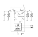
- FIG. 1 is an electric circuit diagram showing the power supply system in the first embodiment.
- FIG. 2 is a diagram showing a specific configuration of the switch.
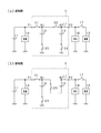
- 3A is a diagram showing a state in which lithium ion storage batteries are connected in parallel
- FIG. 3B is a diagram showing a state in which lithium ion storage batteries are connected in series
- 4A is a diagram showing a current flow during parallel charging
- FIG. 4B is a diagram showing a current flow during parallel discharging
- FIG. 5 is a diagram showing the flow of current during series discharge
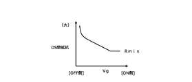
- FIG. 6 is a diagram showing the relationship between the gate voltage and the drain-source resistance.
- FIG. 7 is a flowchart showing a processing procedure for controlling the connection state and charge / discharge current of the lithium ion storage battery
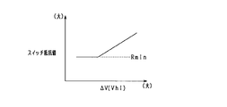
- FIG. 8 is a diagram showing the relationship between the terminal voltage difference ⁇ V and the switch resistance value.
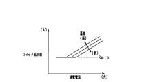
- FIG. 9 is a diagram showing the relationship between the switch temperature and the switch resistance value.
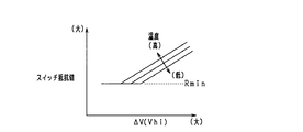
- FIG. 10 is a diagram showing the relationship among the terminal voltage difference ⁇ V, the switch temperature, and the switch resistance value.
- FIG. 11 is a time chart for more specifically explaining resistance value control associated with series-parallel switching of a lithium ion storage battery
- FIG. 12 is a time chart showing a change in energization current when switching a lithium ion storage battery from a serial state to a parallel state;
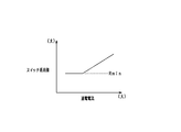
- FIG. 13 is a diagram illustrating a relationship between the energization current and the switch resistance value.
- FIG. 14 is a diagram illustrating a relationship among energization current, switch temperature, and switch resistance value.
- an in-vehicle power supply device that supplies electric power to various devices of the vehicle in a vehicle that runs using an engine (internal combustion engine) as a drive source is embodied.
- the power supply system is a so-called dual power supply system including a first power storage device having a lead storage battery and a second power storage device having a plurality of lithium ion storage batteries as the power storage device. .
- the power supply system includes a lead storage battery 11 and two lithium ion storage batteries 12 and 13, and from each storage battery 11 to 13 to various electric loads 14 and 15 and a rotating electrical machine 16. Can be fed. Further, each of the storage batteries 11 to 13 can be charged by the rotating electrical machine 16.
- the lead storage battery 11 is a well-known general-purpose storage battery.
- the lithium ion storage batteries 12 and 13 are high-density storage batteries that have less power loss in charge and discharge and higher output density and energy density than the lead storage battery 11.
- the lithium ion storage batteries 12 and 13 may be storage batteries having higher energy efficiency during charging / discharging than the lead storage battery 11.
- the lithium ion storage batteries 12 and 13 are each configured as an assembled battery having a plurality of single cells.
- the rated voltages of the storage batteries 11 to 13 are the same, for example, 12V.
- the two lithium ion storage batteries 12 and 13 are housed in a housing case and configured as an integral battery unit U.
- the battery unit U has two output terminals P1 and P2, among which the lead storage battery 11 and the electric load 14 are connected to the output terminal P1, and the electric load 15 and the rotating electrical machine 16 are connected to the output terminal P2. Has been.
- the electrical load 14 connected to the output terminal P1 is a 12V system load driven based on 12V power supply from the lead storage battery 11 or the lithium ion storage batteries 12 and 13.
- the electric load 14 includes a constant voltage request load that is required to be constant or at least stable so that the voltage of the supplied power fluctuates within a predetermined range, and a general electric load other than the constant voltage request load. It is.
- the constant voltage required load is a load to be protected and is a load in which power supply failure is not allowed. Specific examples of the constant voltage required load include various ECUs such as a navigation device, an audio device, a meter device, and an engine ECU.
- the electric load 15 is a high-voltage load in which a large driving force is temporarily required, for example, when the vehicle is traveling, that is, a high power requirement may occur.
- a specific example is an electric steering device.
- the electric load 14 connected to the output terminal P1 corresponds to a low voltage electric load
- the electric load 15 and the rotating electrical machine 16 connected to the output terminal P2 correspond to a high voltage electric load.
- the rotating shaft of the rotating electrical machine 16 is drivingly connected to an engine output shaft (not shown) by a belt or the like.
- the rotating shaft of the rotating electrical machine 16 is rotated by the rotation of the engine output shaft, while the rotating shaft of the rotating electrical machine 16 is rotated.
- the rotating electrical machine 16 is an MG (Motor Generator), and has a power generation function for generating power (regenerative power generation) by rotation of the engine output shaft and the axle, and a power running function for applying rotational force to the engine output shaft.
- the rotating electrical machine 16 is configured to perform adjustment of the generated current during power generation and torque adjustment during powering driving by an inverter as a power conversion device provided integrally or separately.
- the engine is started and torque assist is performed by driving the rotating electrical machine 16.
- the rotating electrical machine 16 is an electric load in terms of adding power to the engine output shaft, and is a high power / high current load in comparison with the electric load 14.
- a switch 17 is provided between the electric load 15 and the rotating electrical machine 16, and the storage batteries 11 to 13 and the rotating electrical machine 16 and the electrical load 15 are electrically connected or disconnected by turning on or off the switch 17. It is like that.
- the two lithium ion storage batteries 12 and 13 can be switched between a parallel connection state and a serial connection state, which will be described in detail.
- switches 21 and 22 are provided in series on the electric path L1 between the output terminals P1 and P2.
- the electrical path L1 is also a part of the energization path where the electrical loads 14 and 15 and the rotating electrical machine 16 are connected to the lead storage battery 11 in the present system.
- the positive terminal (positive terminal) of the lithium ion storage battery 12 is connected to the first point N1 between the switches 21 and 22, and the positive terminal of the lithium ion storage battery 13 is connected to the second point N2 between the switch 22 and the output terminal P2. It is connected.
- switches 23 and 24 are provided between the negative terminals of the lithium ion storage batteries 12 and 13 and the ground, respectively.
- the first point N1 is connected to a third point N3 between the negative terminal of the lithium ion storage battery 13 and the switch 24, and a switch 25 is provided in the connection path.
- the switches 21 to 25 correspond to “switching units”.
- Each of the switches 21 to 25 is composed of a semiconductor switching element such as a MOSFET, IGBT, or bipolar transistor.
- each of the switches 21 to 25 is configured by a MOSFET, and the switches 21 to 25 are turned on and off according to application of a predetermined gate voltage.
- each of the switches 21 to 25 is configured to have two sets of MOSFETs, and the parasitic diodes of each set of MOSFETs are connected in series so that they are opposite to each other. Good.
- the parasitic diodes that are opposite to each other completely cut off the current that flows through the path in which the switches 21 to 25 are turned off.
- the configuration using semiconductor switching elements in each of the switches 21 to 25 may be arbitrary. For example, a configuration in which parasitic diodes of MOSFETs are not arranged in opposite directions may be used.
- FIG. 3A shows a state in which the lithium ion storage batteries 12 and 13 are connected in parallel
- FIG. 3B shows a state in which the lithium ion storage batteries 12 and 13 are connected in series.
- the energization path shown in FIG. 3A is a “parallel energization path”
- the energization path shown in FIG. 3B is a “series energization path”.
- the switch 17 is turned off in the parallel state and turned on as necessary in the series state.
- the switches 21 to 24 are turned on and the switch 25 is turned off.
- the lithium ion storage batteries 12 and 13 are in a parallel relationship.
- the output voltages of the output terminals P1 and P2 are both approximately 12V.
- the lead storage battery 11 and the lithium ion storage batteries 12 and 13 are connected in parallel to the electric load 14 on the P1 side, and the lead storage battery 11 and the lithium ion storage battery are connected in parallel to the rotating electrical machine 16 on the P2 side. 12 and 13 are connected.
- the electrical load 14 is connected to an intermediate position (first point N1) on the path connecting the positive electrodes of the lithium ion storage batteries 12 and 13 together.
- the switches 21, 23 and 25 are on and the switches 22 and 24 are off.
- the lithium ion storage batteries 12 and 13 are connected in series. It has become.
- the output voltage of the output terminal P1 is approximately 12V
- the output voltage of the output terminal P2 is approximately 24V.
- the lead storage battery 11 and the lithium ion storage battery 12 are connected in parallel to the electric load 14 on the P1 side.
- lithium ion storage batteries 12 and 13 are connected in series to the rotating electrical machine 16 on the P2 side.
- the rotating electrical machine 16 is connected to a position (second point N2) on the positive electrode side of the storage battery 13 on the high voltage side among the lithium ion storage batteries 12 and 13.
- the rotating electrical machine 16 is capable of 12V powering driving with a power supply voltage of 12V and 24V powering driving with a power supply voltage of 24V.
- the rotating electrical machine 16 When the lithium ion storage batteries 12 and 13 are connected in parallel, the rotating electrical machine 16 The rotary electric machine 16 is driven by 24V in a state where the battery is driven by 12V and the lithium ion batteries 12 and 13 are connected in series.
- the electric load 15 connected to the output terminal P2 is driven by 24V with the lithium ion storage batteries 12 and 13 connected in series.
- the battery unit U has a control unit 30 constituting battery control means.
- the control unit 30 switches on / off (opening / closing) the switches 21 to 25 in the battery unit U.
- the control unit 30 controls on / off of the switches 21 to 25 based on the running state of the vehicle and the storage states of the storage batteries 11 to 13.
- charging / discharging is implemented using the lead storage battery 11 and the lithium ion storage batteries 12 and 13 selectively.
- the charge / discharge control based on the storage state of each of the storage batteries 11 and 12 will be briefly described.
- each lithium ion storage battery 12 and 13 is each provided with the voltage sensor which detects a terminal voltage for every storage battery, and the current sensor which detects an energization current for every storage battery, respectively.
- the detection result of the sensor is input to the control unit 30.
- the control unit 30 sequentially acquires the terminal voltage detection values of the lead storage battery 11 and the lithium ion storage batteries 12 and 13 and sequentially acquires the energization currents of the lead storage battery 11 and the lithium ion storage batteries 12 and 13. And based on these acquired values, while calculating OCV (open circuit voltage: OpenageCircuit Voltage) and SOC (residual capacity: State Of Charge) of the lead storage battery 11 and the lithium ion storage batteries 12, 13, the OCV and SOC are calculated. The amount of charge and the amount of discharge to the lithium ion storage batteries 12 and 13 are controlled so as to be maintained within a predetermined use range.
- OCV open circuit voltage: OpenageCircuit Voltage
- SOC residual capacity: State Of Charge
- the lithium ion storage batteries 12 and 13 are basically brought into a parallel state so that the load drive request on the output terminal P2 side and the high voltage power generation for the rotating electrical machine 16 are performed.
- Each of the lithium ion storage batteries 12 and 13 can be switched to a series state in response to the above request.
- the control unit 30 temporarily switches the lithium ion storage batteries 12 and 13 from the parallel state to the serial state based on, for example, a drive request for the electric steering device (electric load 15) or a torque assist request by the rotating electrical machine 16. Implement control.
- the ECU 40 is connected to the control unit 30.
- the control unit 30 and the ECU 40 are connected by a communication network such as CAN and can communicate with each other, and various data stored in the control unit 30 and the ECU 40 can be shared with each other.
- the ECU 40 is an electronic control device having a function of performing idling stop control of the vehicle.
- the idling stop control automatically stops the engine when a predetermined automatic stop condition is satisfied, and restarts the engine when the predetermined restart condition is satisfied under the automatic stop state.
- the engine is started by the rotating electric machine 16 when the idling stop control is automatically restarted.
- FIG. 4A shows the current flow during parallel charging
- FIG. 4B shows the current flow during parallel discharging.
- a generated current is output from the rotating electrical machine 16, and the lead storage battery 11 and the lithium ion storage batteries 12 and 13 are charged and the electric load 14 is fed by the generated current.
- the switches 22 and 23 exist in the charging path of the lithium ion storage battery 12, and the charging current Iin 1 flows according to the path resistance including the switches 22 and 23.
- a switch 24 exists in the charging path to the lithium ion storage battery 13, and a charging current Iin 2 flows according to path resistance including the switch 24.
- the lithium ion storage battery 13 discharges with the electric load 15 and the rotating electrical machine 16 being discharged, whereas the lithium ion storage battery 12 has the electrical load 15 and the rotating electrical machine. In addition to 16, the electric load 14 is discharged. Therefore, the discharge current Iout1 of the lithium ion storage battery 12 becomes larger than the discharge current Iout2 of the lithium ion storage battery 13, thereby further increasing the SOC difference between the storage batteries 12 and 13.
- the SOC of each lithium ion storage battery 12 and 13 is varied, there is a disadvantage that the use area of each storage battery 12 and 13 cannot be fully utilized.
- a parameter having a correlation with the magnitude of the current flowing between the lithium ion storage batteries 12 and 13 is acquired, and current suppression control is appropriately performed based on the parameter.
- a storage state parameter indicating the state of each lithium ion storage battery 12 and 13 and a switch state parameter indicating the state of each switch 21 to 25 are acquired.
- the switch resistance value is adjusted with any one of the switches 21 to 25 as an adjustment target.
- the switch resistance value is adjusted using the switch 22 as an adjustment target.
- switch resistance value will be adjusted by making switch 25 into adjustment object.
- the control unit 30 corresponds to an “acquisition unit” and a “resistance control unit”.
- the storage state parameter for example, at least one of the terminal voltage, SOC, and charge / discharge current of each lithium ion storage battery 12, 13 is acquired.
- the temperature of each lithium ion storage battery 12 and 13 is acquired.
- the switch state parameter for example, the temperatures of the switches 21 to 25 are acquired.
- the control unit 30 exists at an intermediate position between the storage batteries 12 and 13 in the parallel energization path based on the storage state parameters of the lithium ion storage batteries 12 and 13 in order to suppress overcurrent.
- the resistance value of the switch 22 is adjusted to be increased.
- the control unit 30 acquires the difference ⁇ V between the terminal voltages of the lithium ion batteries 12 and 13 and performs feedback control based on the ⁇ V, thereby controlling the resistance value of the switch 22 to a desired value.
- the resistance value of the switch 22 is controlled by controlling the gate voltage of the switch 22. Thereby, the resistance value in the ON state of the switch 22 is increased, and accordingly, the current between the storage batteries is reduced. By this control, the current between the storage batteries is feedback-controlled to a desired value.
- the resistance value control of the switch 22 for example, by using the relationship between the gate voltage Vg and the drain-source resistance shown in FIG. 6, and adjusting the drain-source resistance by controlling the gate voltage Vg, the resistance value of the switch 22, As a result, the path resistance value between the lithium ion storage batteries 12 and 13 is changed.
- the relationship in which the drain-source resistance increases by lowering the gate voltage Vg is defined with reference to the resistance value Rmin in the normally on state, and the switch resistance value (drain-source resistance) is higher than Rmin. It is variably set to the larger side.
- each lithium ion storage battery 12 and 13 is used as the storage state parameter to determine whether or not an overcurrent flows, and each lithium ion storage battery 12 is subjected to the overcurrent flow. , 13 and the resistance value of the switch 22 can be controlled based on the charge / discharge current.
- the current suppression control is performed using the switch state parameter in addition to the storage state parameter.
- the control unit 30 sets the switch 22 as an adjustment target in the parallel state, and acquires the temperature of the switch 22 as a switch state parameter. And in order to reduce the electric current between storage batteries, it adjusts to the side which makes the resistance value of switch 22 large based on switch temperature.
- the control unit 30 controls the resistance value of the switch 22 to a desired value by feedback controlling the temperature of the switch 22. Thereby, the resistance value in the ON state of the switch 22 is increased, and accordingly, the current between the storage batteries is reduced.
- the energization path shown in FIG. 3B is formed in the battery unit U, and if the power supply voltage composed of both lithium ion storage batteries 12 and 13 is large, the storage batteries 12 and 13 and the electrical load 15 or There is a concern that an overcurrent flows in the energization path to the rotating electrical machine 16. Actually, there is a concern that an overcurrent flows through a smoothing capacitor provided in the electric load 15 or the rotating electrical machine 16. Therefore, the control unit 30 is present at an intermediate position between the storage batteries 12 and 13 in the series energization path based on the storage state parameters of the lithium ion storage batteries 12 and 13 in order to suppress overcurrent. The switch 25 is adjusted so that the resistance value of the switch 25 is increased.
- the control unit 30 acquires the series power supply voltage (synthetic voltage Vhi) from the sum of the terminal voltages of the lithium ion storage batteries 12 and 13, and implements feedback control based on the Vhi, so that the resistance of the switch 25 Control the value to the desired value. More specifically, the resistance value of the switch 25 is controlled by controlling the gate voltage of the switch 25. Thereby, the resistance value in the ON state of the switch 25 is increased, and accordingly, the current between the storage batteries is reduced. By this control, the current between the storage batteries is feedback-controlled to a desired value.
- synthetic voltage Vhi synthetic voltage
- the resistance value of the switch 25 and thus the resistance value of the switch 25 is adjusted by adjusting the drain-source resistance by controlling the gate voltage Vg, for example, using the relationship of FIG.
- the path resistance value of the energization path between the storage batteries 12 and 13 and the electric load 15 or the rotating electrical machine 16 is changed.
- control unit 30 adjusts the switch 25 in the series state, and acquires the temperature of the switch 25 as a switch state parameter. And in order to reduce the electric current between storage batteries, it adjusts to the side which makes the resistance value of the switch 25 large based on switch temperature. At this time, the control unit 30 controls the resistance value of the switch 25 to a desired value by feedback control of the temperature of the switch 25. Thereby, the resistance value in the ON state of the switch 25 is increased, and accordingly, the current between the storage batteries is reduced.
- the feedforward control is performed at least during a predetermined period from the request to the completion of the switching. The generation of current is suppressed.
- resistance value control is performed using parameters in the state after switching in consideration of the state after switching between the serial state and the parallel state.
- the control unit 30 adjusts the storage state parameters of the lithium ion storage batteries 12 and 13 and the adjustment target existing on the energization path in the parallel state during a predetermined period from the time of the switching request.
- the state parameters of the switch 22 are acquired, and feedforward control is performed based on these parameters.
- control unit 30 adjusts the power storage state parameters of the lithium ion storage batteries 12 and 13 and the current path on the current path in the serial state during a predetermined period from the time of the switching request.
- the state parameters of the target switch 25 are acquired, and feedforward control is performed based on these parameters.
- FIG. 7 is a flowchart showing a processing procedure for controlling the connection state and charging / discharging current of each lithium ion storage battery 12, 13, and this processing is repeatedly performed by the control unit 30 at a predetermined cycle. This process is performed both when the lithium ion storage batteries 12 and 13 are discharged and charged. However, it may be performed only at the time of discharging or charging.
- step S11 the storage state parameter is acquired, and in step S12, the switch state parameter is acquired.
- the storage state parameter At least one of charge / discharge current, terminal voltage, and SOC detected for each of the lithium ion storage batteries 12 and 13 is acquired as the storage state parameter.
- the temperature of the switches 22 and 25 provided between the lithium ion storage batteries 12 and 13 is acquired as a switch state parameter.
- step S13 it is determined whether or not the state flag for instructing whether the lithium ion storage batteries 12 and 13 are placed in parallel or in series is 1.
- step S14 it is determined whether or not the lithium ion storage batteries 12 and 13 are at the time of switching request from the serial state to the parallel state, that is, whether or not the state flag is switched from “0 ⁇ 1”. For example, when the 24V drive of the electric load 15 and the rotating electrical machine 16 is terminated, a request for switching from the serial state to the parallel state is generated.
- step S15 command the switching of the lithium ion storage batteries 12 and 13 from the serial state to the parallel state.
- the switches 22 and 24 are switched from “OFF ⁇ ON”, and the switch 25 is switched from “ON ⁇ OFF”.
- the switch 25 may be switched off before the switches 22 and 24 are switched on.
- the ON switching of the switches 22 and 24 may be performed with either one first and the other later.
- step S16 it is determined whether or not a predetermined time has elapsed from the switching request from the serial state to the parallel state.
- This predetermined time is a time including a time required for switching the state from serial to parallel and a feedback control delay time, and is, for example, about several to several tens of milliseconds. If step S16 is YES, the process proceeds to step S17, and if step S16 is NO, the process proceeds to step S18.
- step S16 is affirmed.
- step S17 adjustment processing of the switch resistance value in the energization path of each lithium ion storage battery 12 and 13 is performed by feedback control.
- feedback control is performed based on the storage state parameter of each lithium ion storage battery 12 and 13 and the state parameter of the switch 22 to be adjusted existing on the energization path in the parallel state.
- the control unit 30 adjusts the switch resistance value by digital analog control or PWM control (the same applies to steps S18, S22, and S23 described later).
- the control unit 30 calculates the terminal voltage difference ⁇ V using the terminal voltages of the lithium ion batteries 12 and 13 as the storage state parameters. Then, using the relationship of FIG. 8, the adjustment resistance value of the switch 22 is determined based on the terminal voltage difference ⁇ V. In FIG. 8, a relationship is defined such that the adjustment resistance value of the switch 22 becomes larger as the terminal voltage difference ⁇ V is larger. The adjustment resistance value is set larger than the resistance value (minimum value Rmin) in the full-on state of the switch 22 (the same applies to FIGS. 9 and 10 described later).
- control part 30 determines the adjustment resistance value of the switch 22 based on the temperature of the switch 22 as a switch state parameter using the relationship of FIG. In FIG. 9, a relationship is defined in which the adjustment resistance value of the switch 22 becomes larger as the switch temperature is higher.
- the switch resistance value is calculated based on the storage state parameter and the switch resistance value is calculated based on the switch state parameter
- the larger one of the resistance values of the switch 22 calculated for each of them. May be determined as the adjustment resistance value of the switch 22 employed this time.
- the resistance value calculated using the relationship of FIG. 8 is R1
- the resistance value calculated using the relationship of FIG. 9 is R2, and R1> R2, then the resistance value R1 is used as the switch that is employed this time. 22 is determined as the adjustment resistance value.
- the smaller one of the switch resistance value calculated based on the storage state parameter and the switch resistance value calculated based on the switch state parameter is determined as the adjustment resistance value of the switch 22 employed this time
- the average value of each switch resistance value may be determined as the adjustment resistance value of the switch 22 employed this time.
- the adjustment resistance value of the switch 22 may be determined using the relationship of FIG. In FIG. 10, the relationship between the terminal voltage difference ⁇ V of each lithium ion storage battery 12, 13, the temperature of the switch 22, and the adjustment resistance value of the switch 22 is defined. In this case, the adjustment resistance value of the switch 22 is set based on each parameter described above.
- step S18 the switch resistance value adjustment process in the parallel energization path of each lithium ion storage battery 12 and 13 is performed by feedforward control.
- the feedforward control is performed based on the storage state parameter of each lithium ion storage battery 12 and 13 and the state parameter of the switch 22 to be adjusted existing on the energization path in the parallel state.
- step S18 is performed, but at this point, switching to the parallel state is not yet completed. Therefore, it is not possible to acquire the storage state parameter under the parallel state. Therefore, in the serial state, the control unit 30 acquires the terminal voltage of each lithium ion storage battery 12 and 13 as the storage state parameter, and based on each terminal voltage, the difference ⁇ V between the terminal voltages of each storage battery 12 and 13. Is calculated. Then, the adjustment resistance value of the switch 22 is determined based on the terminal voltage difference ⁇ V. At this time, the adjustment resistance value of the switch 22 may be set using the relationship of FIG. In step S18, the storage state parameter in the series state is acquired as the storage state parameter in the parallel state.
- control unit 30 acquires the temperature of the switch 22 on the parallel energization path as the switch state parameter, and determines the adjustment resistance value of the switch 22 based on the switch temperature.
- the adjustment resistance value of the switch 22 may be set using the relationship of FIG.
- the switch 22 calculated by each of them is calculated.
- the larger one of the resistance values may be determined as the resistance value of the switch 22 employed this time.
- the resistance value of the switch 22 may be determined using the relationship of FIG.
- step S20 command the switching of the lithium ion storage batteries 12 and 13 from the parallel state to the serial state.
- the switches 22 and 24 are switched from “ON ⁇ OFF”, and the switch 25 is switched from “OFF ⁇ ON”.
- the switches 22 and 24 may be switched off first, and the switch 25 may be switched on later. Further, the switching of the switches 22 and 24 may be performed with either one first and the other later. By switching on / off these switches 22, 24, 25, the lithium ion storage batteries 12, 13 shift to a serial state.
- step S21 it is determined whether or not it is after a predetermined time has elapsed from the switching request from the parallel state to the serial state. This predetermined time is a time taken in consideration of the time required for switching the state from parallel to serial and the feedback control delay time, and is, for example, about several to several tens of milliseconds. If step S21 is YES, the process proceeds to step S22, and if step S21 is NO, the process proceeds to step S23.
- step S22 adjustment processing of the switch resistance value in the energization path of each lithium ion storage battery 12 and 13 is performed by feedback control.
- feedback control is performed based on the storage state parameter of each lithium ion storage battery 12 and 13 and the state parameter of the switch 25 to be adjusted existing on the energization path in the series state. Thereby, the electric current which flows between the lithium ion storage batteries 12 and 13 is controlled to a desired value.
- the control unit 30 uses the terminal voltage of each of the lithium ion storage batteries 12 and 13 as the storage state parameter, and uses the combined voltage Vhi (that is, the output terminal P2) of the lithium ion storage batteries 12 and 13 in the series state. Voltage value). Then, using the relationship shown in FIG. 8 (where the horizontal axis is Vhi), the adjustment resistance value of the switch 25 is determined based on the voltage Vhi. In FIG. 8, a relationship is defined such that the adjustment resistance value of the switch 25 becomes larger as the voltage Vhi is larger. Or the control part 30 determines the adjustment resistance value of the switch 25 based on the temperature of the switch 25 as a switch state parameter using the relationship of FIG.
- the switch resistance value is calculated based on the storage state parameter and the switch resistance value is calculated based on the switch state parameter, for example, among the resistance values of the switch 25 calculated in each of them The larger one may be determined as the adjustment resistance value of the switch 25 employed this time.
- the adjustment resistance value of the switch 25 may be determined using the relationship shown in FIG. 10 (where the horizontal axis is Vhi). In FIG. 10, the relationship among the combined voltage Vhi of each lithium ion storage battery 12, 13, the temperature of the switch 25, and the adjustment resistance value of the switch 25 is defined. In this case, the adjustment resistance value of the switch 25 is set based on the above parameters.
- step S23 the switch resistance value adjustment process in the series energization path of each lithium ion storage battery 12 and 13 is performed by feedforward control.
- feedforward control is performed based on the storage state parameter of each lithium ion storage battery 12 and 13 and the state parameter of the switch 25 to be adjusted existing on the energization path in the series state.
- step S23 is performed, but at this point, switching to the serial state is incomplete. Therefore, it is not possible to acquire the storage state parameter under the series state. Therefore, in the parallel state, the control unit 30 acquires the terminal voltage of each lithium ion storage battery 12 and 13 as the storage state parameter, and calculates the combined voltage Vhi of each storage battery 12 and 13 based on each terminal voltage. To do. Then, the adjustment resistance value of the switch 25 is determined based on the combined voltage Vhi. At this time, the adjustment resistance value of the switch 25 may be set using the relationship of FIG. 8 (where the horizontal axis is Vhi). In step S23, the storage state parameter in the parallel state is acquired as the storage state parameter in the series state.
- control unit 30 acquires the temperature of the switch 25 on the series energization path as the switch state parameter, and determines the adjustment resistance value of the switch 25 based on the switch temperature.
- the adjustment resistance value of the switch 25 may be set using the relationship of FIG.
- the switch 25 calculated in each of them is calculated.
- the larger one of the resistance values may be determined as the resistance value of the switch 25 employed this time.
- the resistance value of the switch 25 may be determined using the relationship shown in FIG. 10 (where the horizontal axis is Vhi).
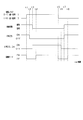
- FIG. 11 is a time chart for more specifically explaining the resistance value control accompanying the series-parallel switching of the lithium ion storage batteries 12 and 13.
- switching from the serial state to the parallel state is performed by the switching operation of the switches 21 to 25 during the period from t1 to t3.
- the switch 25 is first switched from “ON ⁇ OFF” among the switches 21 to 25 of the battery unit U, and at the subsequent timing t3, the switches 22 and 24 are switched from “OFF ⁇ ON”. Can be switched. Switching to the parallel state is completed at timing t3. At this time, since the switch 25 is turned off first, the ground fault in each lithium ion storage battery 12 and 13 is suppressed.
- the switch resistance value in the energization path of each lithium ion storage battery 12 and 13 is adjusted by feedforward control.
- the switch 22 existing in the inter-battery path in the parallel state is set as an adjustment target, and the switch is set so that an excessive current does not flow through the switch 22 in the parallel state.
- the resistance value is adjusted. That is, in the predetermined period “t1 to t4” including the timing t3 when the parallel switching is completed, the switch resistance value is adjusted by feedforward control using the parameters under the series state acquired as the parameters in the parallel state.
- the switch resistance value in the energization path of each lithium ion storage battery 12 and 13 is adjusted by feedback control.
- the switch 22 is set as an adjustment target, and the switch resistance value is adjusted so that an excessive current does not flow through the switch 22.
- switching from the parallel state to the serial state is performed by the switching operation of the switches 21 to 25 during the period from t5 to t7.
- the switches 22 and 24 are switched from “ON ⁇ OFF” first, and at the subsequent timing t7, the switch 25 is switched from “OFF ⁇ ON”. Can be switched.
- Switching to the serial state is completed at timing t7. At this time, when the switch 25 is switched to ON later, the ground fault in each lithium ion storage battery 12 and 13 is suppressed.
- the switch resistance value in the energization path of each lithium ion storage battery 12 and 13 is adjusted by feedforward control.
- the switch 25 existing in the inter-battery path in the series state is to be adjusted, and the switch is set so that an excessive current does not flow through the switch 25 in the series state.
- the resistance value is adjusted. That is, in a predetermined period “t5 to t8” including the timing t7 when the series switching is completed, the switch resistance value is adjusted by feedforward control using the parameters under the parallel state acquired as the respective parameters in the series state.
- FIG. 12 is a time chart showing changes in energization current when the lithium ion storage batteries 12 and 13 are switched from the series state to the parallel state.
- the energization current value shown in FIG. 12 is a current value that flows through the switch 22 located in the energization path between the lithium ion batteries 12 and 13 in a parallel state, and the solid line indicates the current change obtained by the control of the present embodiment.
- An alternate long and short dash line indicates a change in current when the control of this embodiment is not performed.
- a request for switching from the serial state to the parallel state occurs at timing t11, and switching from the serial state to the parallel state is completed by switching operation of the switches 21 to 25 at timing t12.
- the feedforward control is performed in a period TX (t11 to t13) including the timing t12.
- the switch resistance value in the energization path of each lithium ion storage battery 12 and 13 is adjusted by feedback control.
- the adjustment resistance value of the switch 22 is determined based on the difference ⁇ V between the terminal voltages of the lithium ion storage batteries 12 and 13.
- the energization current value is controlled with the overcurrent threshold Th as the upper limit.
- the switch resistance value becomes a small value (Rmin). As described above, generation of unnecessary loss is suppressed.
- inrush current may be generated due to discharge from the smoothing capacitor even when switching from the serial state to the parallel state.
- the inrush current can be reduced by adjusting the switch resistance value in the feedforward control.
- a switch state parameter indicating the state of a plurality of switches for series-parallel switching is acquired, and the resistance value of the switch existing in the energization path in the parallel state or series state is adjusted based on the switch state parameter. I tried to do it.
- the switch resistance value it is possible to control the current flowing through the energization path in a parallel state or a series state, that is, the current flowing between the lithium ion storage batteries 12 and 13, so that there is a variation in SOC between the storage batteries 12 and 13.
- the lithium ion storage batteries 12 and 13 can be properly used while protecting the lithium ion storage batteries 12 and 13 and the switches.
- the design margin against the overcurrent can be lowered.
- the design relating to overcurrent suppression can be omitted, which in turn can reduce the cost.
- the resistance value of the switch 22 on the parallel energization path or the series energization path in the battery unit U is changed, the resistance value of the switch 22 on the parallel energization path or the resistance value of the switch 25 on the series energization path is increased.
- the configuration is changed. That is, the configuration is such that the resistance value is changed to a larger value with respect to the full-on resistance value (minimum resistance value Rmin) of each of the switches 22 and 25. In this case, it is possible to prevent the charge / discharge current from becoming excessively large, and it is possible to realize a configuration suitable for protecting the switches 21 to 25. Further, considering that the switches 22 and 25 are constituted by semiconductor switching elements such as MOSFETs, the resistance value can be easily adjusted by controlling the gate voltage of the semiconductor switching elements.
- the necessity of current suppression is considered to change depending on the state of the switch existing on the energization path.
- the resistance value is adjusted with the switch 22 on the parallel energization path as the adjustment target based on the switch state parameter, so that the occurrence of overcurrent can be suitably suppressed.
- the switch state parameter in the parallel state is not acquired at the time when the switching is completed, the response to the instantaneous current may be delayed.
- the switch state parameter in the parallel state is obtained after the request for switching to the parallel state and before the parallel switching is completed, the switch resistance value is adjusted by feedforward control. Can respond to instantaneous current quickly.
- the resistance value of the switch 22 existing between the lithium ion storage batteries 12 and 13 is adjusted. In this case, a configuration suitable for protecting the lithium ion storage batteries 12 and 13 can be realized.
- the resistance value is adjusted with the switch 25 on the series energization path as the adjustment target based on the switch state parameter, so that the occurrence of overcurrent can be suitably suppressed.
- the response to the instantaneous current may be delayed if the switch state parameter in the serial state is not acquired when the switching is completed.
- the switch state parameter in the serial state is acquired and the switch resistance value is adjusted by feedforward control before the completion of the serial switching after the request for switching to the serial state, Can respond to instantaneous current quickly.
- the resistance value of the switch 25 between the lithium ion storage batteries 12 and 13 among the switches 23 and 25 existing on the series energization path is adjusted under the series state. In this case, a configuration suitable for protecting the lithium ion storage batteries 12 and 13 can be realized.
- the switch temperature is acquired as the switch state parameter, and the switch resistance value is adjusted based on the acquisition result.
- the feedback control is performed in consideration of the switch temperature, so that a more preferable configuration can be realized for protecting each switch.
- the switch state parameter is obtained by acquiring the energization current of any switch and adjusting the switch resistance value based on the acquisition result. In this case, feedback control can be realized according to the actual switch state.
- the magnitude of the current flowing through each of the energization paths varies depending on the storage state of the lithium ion storage batteries 12 and 13.
- the switch resistance value is adjusted based on the storage state parameter of each lithium ion storage battery 12, 13, appropriate current control can be performed in each energization path.
- the storage state parameter at least one of the charge / discharge current, terminal voltage, and SOC of each lithium ion storage battery 12 and 13 is acquired, and the switch resistance value is adjusted based on the acquisition result. In this case, feedback control can be realized in accordance with the actual storage state of each lithium ion storage battery 12, 13.
- each lithium ion storage battery 12 and 13 is acquired as a storage state parameter, and the switch resistance value is adjusted based on the acquisition result. In this case, by implementing feedback control in consideration of the battery temperature, it is possible to realize a more preferable configuration for protecting each of the storage batteries 12 and 13.
- the switch resistance value is adjusted at least during discharging or charging of each of the lithium ion storage batteries 12 and 13. Thereby, the use suitable in the battery unit U which has the lithium ion storage batteries 12 and 13 as a secondary battery is realizable.
- switches 21 to 25 are composed of semiconductor switching elements, desired current control can be easily performed by MOSFET gate voltage control or the like.
- each switch 21 to 25 a pair of MOSFETs was used, and a configuration in which the parasitic diodes of these MOSFETs were connected in series so as to be opposite to each other was adopted. As a result, when the switches 21 to 25 are turned off, the current flowing through the energization path can be suitably cut off.
- the switches 21 to 25 for switching between series and parallel are used as the resistance variable section, and the current control is performed by adjusting the switch resistance value.
- current control is performed by utilizing the on-resistance generated in each of the switches 21 to 25, so that the current flowing through each of the lithium ion storage batteries 12 and 13 and the switch can be set to a desired value without complicating the configuration. Can be controlled as follows.
- the gate voltage control is performed by digital analog control or PWM control for each of the switches 21 to 25 whose resistance value is to be adjusted. Thereby, the desired resistance value can be easily adjusted.
- PWM control theoretically, the loss due to the current becomes zero when the duty is off, so that a highly efficient system can be realized.
- the path resistance value is controlled by using the switch for series / parallel switching provided as the basic function of the battery unit U and the control unit 30 for performing the switching control, so that there is nothing to the basic unit configuration.
- a process for adjusting a desired resistance value can be realized without adding an element or the like.
- the energization current of the lithium ion storage batteries 12 and 13, the SOC may be performed using at least one of them.
- the configuration may be such that two or more of the charge / discharge current, the terminal voltage, and the SOC are acquired as the storage state parameter, and the switch resistance value is adjusted using them. In this case, by increasing the number of acquisition parameters, it is possible to improve the accuracy of current control and increase the margin for breakdown.
- the switch resistance value may be set based on the relationship shown in FIG. 9 or 10 after the “temperature” in FIG. 9 or 10 is set as the battery temperature.
- the battery temperature is a parameter that can be acquired at any timing regardless of the series-parallel state (that is, the switch state), unlike the electrical parameters such as the charge / discharge current, the terminal voltage, and the SOC.
- the thirteen states can be suitably monitored.
- the switch resistance value is set based on the switch energization current using the relationship of FIG.
- the switch resistance value is set based on the switch energization current and the switch temperature using the relationship of FIG. Also in this case, feedback control can be realized according to the actual switch state.
- the switch resistance value is adjusted using both the storage state parameter and the switch state parameter.
- the switch resistance value is changed using only one of these parameters. It is good also as a structure which adjusts.
- the resistance value adjustment is performed with the switch 22 as an adjustment target in the parallel state, and the resistance value adjustment is performed with the switch 25 as the adjustment target in the series state, but this may be changed. Any configuration may be used as long as the resistance value is adjusted by adjusting at least one of the switches 22, 23, and 24 existing in the parallel energization path in the parallel state. Moreover, what is necessary is just a structure which adjusts resistance value by making at least 1 of the switches 23 and 25 which exist in a series electricity supply path
- the switch for obtaining the switch state parameter may be different from the switch for resistance adjustment.
- a switch state parameter is acquired for the switch 22 among the switches 22, 23, and 24 existing in the parallel energization path in the parallel state, and the resistance value is adjusted for either of the switches 23 and 24.
- the switch state parameter is acquired for the switch 23 and the resistance value is adjusted for the switch 25.
- An overcurrent threshold for determining that an overcurrent has flowed through the energization path including the path between the lithium ion storage batteries 12 and 13 is determined, and the control unit 30 determines whether there is an overcurrent based on the overcurrent threshold. It is good also as a structure to determine. In such a case, the control unit 30 is configured to set the overcurrent threshold based on at least one of the charge / discharge current, the terminal voltage, the SOC, and the battery temperature as the storage state parameter. At this time, if the overcurrent is likely to flow, the overcurrent threshold may be reduced. It is also possible to adopt a configuration in which the overcurrent threshold is set based on at least one of the switch energization current and the switch temperature as the switch state parameter.
- a configuration using a battery other than the lithium ion storage battery may be used as the plurality of power storage means.
- any of a configuration using a storage battery other than a lithium ion storage battery, a configuration using a storage battery and a capacitor, and a configuration using a plurality of capacitors may be used as the plurality of power storage means.
- the resistance value at the time of switching on the switch for series-parallel switching of a plurality of lithium ion batteries is adjusted, and thereby the charge / discharge current for each lithium ion battery is individually controlled. May be changed.
- another switch composed of a semiconductor switching element is provided in addition to the switch for series / parallel switching, and the on-resistance value of the other switch is adjusted, thereby charging and discharging each lithium ion storage battery. It is good also as a structure which controls an electric current separately.
- variable resistance portion In addition to using a semiconductor switching element as the variable resistance portion, it is also possible to use a variable resistor.
Landscapes
- Engineering & Computer Science (AREA)
- Chemical & Material Sciences (AREA)
- Manufacturing & Machinery (AREA)
- Chemical Kinetics & Catalysis (AREA)
- Electrochemistry (AREA)
- General Chemical & Material Sciences (AREA)
- Power Engineering (AREA)
- Combustion & Propulsion (AREA)
- Mechanical Engineering (AREA)
- General Engineering & Computer Science (AREA)
- Charge And Discharge Circuits For Batteries Or The Like (AREA)
- Secondary Cells (AREA)
Abstract
This power supply system comprises: a plurality of electricity storage means (12, 13); and a selector unit which has a plurality of switching means (21-25) provided to electrical paths which connect to each of the electricity storage means, and which selects between a parallel state in which the plurality of electricity storage means are connected to one another in parallel, and a serial state in which the plurality of electricity storage means are connected to one another in series. The power supply control device (30) comprises: an acquisition unit which acquires a switching state parameter which is correlated with the magnitude of the current flowing on the current-carrying path that includes a path between each of the electricity storage means in the parallel state or the serial state, as a parameter indicating the state of the plurality of switching means; and a resistance control unit which adjusts the resistance value of a variable resistor present on the current-carrying path in the parallel state or the series state on the basis of the switching state parameter.
Description
本出願は、2016年7月11日に出願された日本出願番号2016-136630号に基づくもので、ここにその記載内容を援用する。
This application is based on Japanese Application No. 2016-136630 filed on July 11, 2016, the contents of which are incorporated herein by reference.
本開示は、複数の蓄電手段を備える電源システムに適用される電源制御装置、及び電源システムに関するものである。
The present disclosure relates to a power supply control device applied to a power supply system including a plurality of power storage means and a power supply system.
従来、複数の蓄電池を備える電源装置において、エンジン運転状態に応じて、複数の蓄電池を並列接続した状態と直列接続した状態とを切り替えるようにした技術が知られている(例えば特許文献1参照)。具体的には、エンジン自動始動システムにおいて、エンジン運転中は、接続切替手段としてのリレーにより各蓄電池を並列接続の状態にして、発電機により各蓄電池を充電する。また、エンジン自動停止後の再始動時には、リレーにより各蓄電池を直列接続の状態に切り替え、始動機への給電を実施する。そして上記構成により、エンジン始動を円滑にし、かつ蓄電池が劣化することを抑制することができるとしていた。
2. Description of the Related Art Conventionally, in a power supply device including a plurality of storage batteries, a technique is known that switches between a state in which a plurality of storage batteries are connected in parallel and a state in which they are connected in series according to the engine operating state (for example, see Patent Document 1). . Specifically, in the engine automatic start system, during engine operation, each storage battery is connected in parallel by a relay as a connection switching means, and each storage battery is charged by a generator. Moreover, at the time of restart after an engine automatic stop, each storage battery is switched to the state of a serial connection by a relay, and electric power feeding to a starter is implemented. According to the above configuration, the engine can be started smoothly and the storage battery can be prevented from deteriorating.
しかしながら、上記のように複数の蓄電池の並列接続と直列接続との切り替えを可能にするシステムでは、複数の蓄電池に通じる各通電経路上にそれぞれリレーやスイッチ等の接続切替手段が設けられていること、直列/並列状態で通電経路上のリレーやスイッチ等の個数に違いが生じることにより、各蓄電池で通電経路の抵抗値に違いが生じる。そのため、複数の蓄電池に流れる充放電電流に差違が生じ、結果として各蓄電池で電気残容量(SOC)にばらつきが生じる。そして、各蓄電池でSOCばらつきが生じると、例えば複数の蓄電池を直列状態から並列状態に切り替えた際に、SOC差に起因して蓄電池間の相互で過電流が流れ、ひいては蓄電池やスイッチ等の破損が懸念される。
However, in the system that enables switching between parallel connection and series connection of a plurality of storage batteries as described above, connection switching means such as a relay and a switch are provided on each energization path leading to the plurality of storage batteries. The difference in the number of relays and switches on the energization path in the series / parallel state causes a difference in the resistance value of the energization path in each storage battery. Therefore, a difference arises in the charging / discharging current which flows through a some storage battery, and dispersion | variation arises in an electrical residual capacity (SOC) in each storage battery as a result. Then, when SOC variation occurs in each storage battery, for example, when a plurality of storage batteries are switched from a serial state to a parallel state, an overcurrent flows between the storage batteries due to the SOC difference, which eventually breaks the storage battery, the switch, etc. Is concerned.
本開示は、上記課題に鑑みてなされたものであり、その主たる目的は、直並列の切り替えが可能な複数の蓄電手段を有するシステムにおいて過剰な電流の発生を抑制し、ひいては蓄電手段やスイッチ等の保護を図ることができる電源制御装置、及び電源システムを提供することにある。
The present disclosure has been made in view of the above problems, and its main purpose is to suppress the occurrence of excessive current in a system having a plurality of power storage means that can be switched in series and parallel, and as a result, power storage means, switches, etc. It is an object of the present invention to provide a power supply control device and a power supply system capable of protecting the above.
本開示の電源制御装置は、複数の蓄電手段と、前記各蓄電手段に通じる電気経路に設けられた複数のスイッチ手段を含み、前記複数の蓄電手段について互いに並列接続された並列状態と互いに直列接続された直列状態とを切り替える切替部と、を備える電源システムに適用される。そして、電源制御装置は、前記複数のスイッチ手段の状態を示すパラメータとして、前記並列状態又は前記直列状態での前記各蓄電手段の間の経路を含む通電経路に流れる電流の大きさに相関を持つスイッチ状態パラメータを取得する取得部と、前記スイッチ状態パラメータに基づいて、前記並列状態又は前記直列状態で前記通電経路に存在している抵抗可変部の抵抗値を調整する抵抗制御部と、を備える。
The power supply control device of the present disclosure includes a plurality of power storage means and a plurality of switch means provided in an electrical path leading to each power storage means, and the plurality of power storage means connected in parallel to each other and connected in series to each other Applied to a power supply system including a switching unit that switches between the connected serial states. The power supply control device has a correlation with the magnitude of the current flowing through the energization path including the path between the power storage units in the parallel state or the series state as a parameter indicating the state of the plurality of switch units. An acquisition unit that acquires a switch state parameter; and a resistance control unit that adjusts a resistance value of a resistance variable unit existing in the energization path in the parallel state or the series state based on the switch state parameter. .
複数の蓄電手段を備え、複数のスイッチ手段のオンオフにより各蓄電手段の並列接続と直列接続との切り替えを可能とする電源システムでは、各蓄電手段でのSOC(電気残容量)等に起因して、例えば各蓄電手段間において容量自己調整による過電流が流れることが懸念される。この点、上記構成では、直並列切り替え用の複数のスイッチ手段の状態を示すパラメータとして、並列状態又は直列状態での各蓄電手段の間の経路を含む通電経路に流れる電流の大きさに相関を持つスイッチ状態パラメータを取得し、そのスイッチ状態パラメータに基づいて、並列状態又は直列状態で通電経路に存在している抵抗可変部の抵抗値を調整するようにした。かかる場合、抵抗可変部の抵抗値の調整により、並列状態又は直列状態で通電経路に流れる電流、すなわち蓄電手段どうしで流れる電流等を制御でき、仮に蓄電手段間でSOCばらつきが生じていても、直並列切り替え用のスイッチ手段に過電流が流れること等が抑制される。その結果、蓄電手段やスイッチ等の保護を図りつつ、各蓄電手段の適正な使用を実現できる。
In a power supply system that includes a plurality of power storage means and enables switching between parallel connection and series connection of each power storage means by turning on and off the plurality of switch means, due to SOC (remaining electric capacity) in each power storage means For example, there is a concern that overcurrent due to capacity self-adjustment flows between the respective power storage means. In this regard, in the above configuration, as a parameter indicating the state of the plurality of switch means for series-parallel switching, a correlation is given to the magnitude of the current flowing through the energization path including the path between the power storage means in the parallel state or the series state. The switch state parameter is acquired, and the resistance value of the resistance variable unit existing in the energization path in the parallel state or series state is adjusted based on the switch state parameter. In such a case, by adjusting the resistance value of the resistance variable unit, it is possible to control the current flowing through the energization path in a parallel state or a series state, that is, the current flowing between the power storage units, and even if there is a variation in SOC between the power storage units, It is possible to suppress an overcurrent from flowing through the switching means for series / parallel switching. As a result, proper use of each power storage means can be realized while protecting the power storage means and the switch.
なお、複数の蓄電手段(例えばリチウムイオン蓄電池)の直並列の切り替えが行われる構成としては、直並列切り替え可能な2つ以上の蓄電手段を有する構成であればよく、例えば3つ以上の蓄電手段を備える電源システムにおいて、そのうち少なくとも2つの蓄電手段について直並列の切り替えが行われる構成も含まれる。
Note that a configuration in which a plurality of power storage units (for example, lithium ion storage batteries) are switched in series-parallel may be any configuration having two or more power storage units that can be switched in series-parallel, for example, three or more power storage units. In the power supply system including the above, a configuration in which series-parallel switching is performed for at least two of the power storage units is also included.
本開示についての上記目的およびその他の目的、特徴や利点は、添付の図面を参照しながら下記の詳細な記述により、より明確になる。その図面は、
図1は、第1実施形態における電源システムを示す電気回路図であり、
図2は、スイッチの具体的構成を示す図であり、
図3は、(a)は各リチウムイオン蓄電池を並列接続した状態を示す図、(b)は各リチウムイオン蓄電池を直列接続した状態を示す図であり、
図4は、(a)は並列充電時の電流の流れを示す図、(b)は並列放電時の電流の流れを示す図であり、
図5は、直列放電時の電流の流れを示す図であり、
図6は、ゲート電圧とドレインソース間抵抗との関係を示す図であり、
図7は、リチウムイオン蓄電池の接続状態と充放電電流とを制御する処理手順を示すフローチャートであり、
図8は、端子電圧の差ΔVとスイッチ抵抗値との関係を示す図であり、
図9は、スイッチ温度とスイッチ抵抗値との関係を示す図であり、
図10は、端子電圧の差ΔVとスイッチ温度とスイッチ抵抗値との関係を示す図であり、
図11は、リチウムイオン蓄電池の直並列切り替えに伴う抵抗値制御をより具体的に説明するためのタイムチャートであり、
図12は、リチウムイオン蓄電池を直列状態から並列状態に切り替える際における通電電流の変化を示すタイムチャートであり、
図13は、通電電流とスイッチ抵抗値との関係を示す図であり、
図14は、通電電流とスイッチ温度とスイッチ抵抗値との関係を示す図である。
The above and other objects, features and advantages of the present disclosure will become more apparent from the following detailed description with reference to the accompanying drawings. The drawing
FIG. 1 is an electric circuit diagram showing the power supply system in the first embodiment. FIG. 2 is a diagram showing a specific configuration of the switch. 3A is a diagram showing a state in which lithium ion storage batteries are connected in parallel, FIG. 3B is a diagram showing a state in which lithium ion storage batteries are connected in series, 4A is a diagram showing a current flow during parallel charging, FIG. 4B is a diagram showing a current flow during parallel discharging, FIG. 5 is a diagram showing the flow of current during series discharge, FIG. 6 is a diagram showing the relationship between the gate voltage and the drain-source resistance. FIG. 7 is a flowchart showing a processing procedure for controlling the connection state and charge / discharge current of the lithium ion storage battery, FIG. 8 is a diagram showing the relationship between the terminal voltage difference ΔV and the switch resistance value. FIG. 9 is a diagram showing the relationship between the switch temperature and the switch resistance value. FIG. 10 is a diagram showing the relationship among the terminal voltage difference ΔV, the switch temperature, and the switch resistance value. FIG. 11 is a time chart for more specifically explaining resistance value control associated with series-parallel switching of a lithium ion storage battery, FIG. 12 is a time chart showing a change in energization current when switching a lithium ion storage battery from a serial state to a parallel state; FIG. 13 is a diagram illustrating a relationship between the energization current and the switch resistance value. FIG. 14 is a diagram illustrating a relationship among energization current, switch temperature, and switch resistance value.
以下、本開示を具体化した実施形態を図面に基づいて説明する。本実施形態では、エンジン(内燃機関)を駆動源として走行する車両において当該車両の各種機器に電力を供給する車載電源装置を具体化するものとしている。また、本電源システムは、蓄電装置として、鉛蓄電池を有してなる第1蓄電装置と、複数のリチウムイオン蓄電池を有してなる第2蓄電装置とを備える、いわゆる2電源システムとなっている。
Hereinafter, embodiments embodying the present disclosure will be described with reference to the drawings. In the present embodiment, an in-vehicle power supply device that supplies electric power to various devices of the vehicle in a vehicle that runs using an engine (internal combustion engine) as a drive source is embodied. The power supply system is a so-called dual power supply system including a first power storage device having a lead storage battery and a second power storage device having a plurality of lithium ion storage batteries as the power storage device. .
図1に示すように、本電源システムは、鉛蓄電池11と2つのリチウムイオン蓄電池12,13とを有しており、各蓄電池11~13からは各種の電気負荷14,15と回転電機16への給電が可能となっている。また、各蓄電池11~13に対しては回転電機16による充電が可能となっている。
As shown in FIG. 1, the power supply system includes a lead storage battery 11 and two lithium ion storage batteries 12 and 13, and from each storage battery 11 to 13 to various electric loads 14 and 15 and a rotating electrical machine 16. Can be fed. Further, each of the storage batteries 11 to 13 can be charged by the rotating electrical machine 16.
鉛蓄電池11は周知の汎用蓄電池である。これに対し、リチウムイオン蓄電池12,13は、鉛蓄電池11に比べて、充放電における電力損失が少なく、出力密度、及びエネルギ密度の高い高密度蓄電池である。リチウムイオン蓄電池12,13は、鉛蓄電池11に比べて充放電時のエネルギ効率が高い蓄電池であるとよい。また、リチウムイオン蓄電池12,13は、それぞれ複数の単電池を有してなる組電池として構成されている。これら各蓄電池11~13の定格電圧はいずれも同じであり、例えば12Vである。
The lead storage battery 11 is a well-known general-purpose storage battery. On the other hand, the lithium ion storage batteries 12 and 13 are high-density storage batteries that have less power loss in charge and discharge and higher output density and energy density than the lead storage battery 11. The lithium ion storage batteries 12 and 13 may be storage batteries having higher energy efficiency during charging / discharging than the lead storage battery 11. Moreover, the lithium ion storage batteries 12 and 13 are each configured as an assembled battery having a plurality of single cells. The rated voltages of the storage batteries 11 to 13 are the same, for example, 12V.
図示による詳細な説明は割愛するが、2つのリチウムイオン蓄電池12,13は、収容ケースに収容されて一体の電池ユニットUとして構成されている。電池ユニットUは、2つの出力端子P1,P2を有しており、このうち出力端子P1に鉛蓄電池11と電気負荷14とが接続され、出力端子P2に電気負荷15と回転電機16とが接続されている。
Although detailed explanation by illustration is omitted, the two lithium ion storage batteries 12 and 13 are housed in a housing case and configured as an integral battery unit U. The battery unit U has two output terminals P1 and P2, among which the lead storage battery 11 and the electric load 14 are connected to the output terminal P1, and the electric load 15 and the rotating electrical machine 16 are connected to the output terminal P2. Has been.
出力端子P1に接続される電気負荷14は、鉛蓄電池11又はリチウムイオン蓄電池12,13からの12V給電に基づいて駆動される12V系負荷である。その電気負荷14には、供給電力の電圧が一定又は少なくとも所定範囲内で変動するよう安定であることが要求される定電圧要求負荷と、定電圧要求負荷以外の一般的な電気負荷とが含まれている。定電圧要求負荷は被保護負荷であって、電源失陥が許容されない負荷である。定電圧要求負荷の具体例としては、ナビゲーション装置やオーディオ装置、メータ装置、エンジンECU等の各種ECUが挙げられる。この場合、供給電力の電圧変動が抑えられることで、上記各装置において不要なリセット等が生じることが抑制され、安定動作が実現可能となっている。また、一般的な電気負荷の具体例としては、ヘッドライト等のランプ類やワイパ装置、電動ポンプが挙げられる。
The electrical load 14 connected to the output terminal P1 is a 12V system load driven based on 12V power supply from the lead storage battery 11 or the lithium ion storage batteries 12 and 13. The electric load 14 includes a constant voltage request load that is required to be constant or at least stable so that the voltage of the supplied power fluctuates within a predetermined range, and a general electric load other than the constant voltage request load. It is. The constant voltage required load is a load to be protected and is a load in which power supply failure is not allowed. Specific examples of the constant voltage required load include various ECUs such as a navigation device, an audio device, a meter device, and an engine ECU. In this case, by suppressing the voltage fluctuation of the supplied power, it is possible to suppress an unnecessary reset or the like in each of the above devices, and to realize a stable operation. Specific examples of general electric loads include lamps such as headlights, wiper devices, and electric pumps.
また、電気負荷15は、例えば車両走行時において一時的に大きな駆動力が要求される、すなわち高電力要求が生じることがある高電圧系の負荷である。具体例としては、電動ステアリング装置が挙げられる。なお、出力端子P1に接続される電気負荷14が低電圧電気負荷に相当し、出力端子P2に接続される電気負荷15及び回転電機16が高電圧電気負荷に相当する。
Also, the electric load 15 is a high-voltage load in which a large driving force is temporarily required, for example, when the vehicle is traveling, that is, a high power requirement may occur. A specific example is an electric steering device. The electric load 14 connected to the output terminal P1 corresponds to a low voltage electric load, and the electric load 15 and the rotating electrical machine 16 connected to the output terminal P2 correspond to a high voltage electric load.
回転電機16の回転軸は、図示しないエンジン出力軸に対してベルト等により駆動連結されており、エンジン出力軸の回転によって回転電機16の回転軸が回転する一方、回転電機16の回転軸の回転によってエンジン出力軸が回転する。回転電機16は、MG(Motor Generator)であり、エンジン出力軸や車軸の回転により発電(回生発電)を行う発電機能と、エンジン出力軸に回転力を付与する力行機能とを備えている。回転電機16は、一体又は別体に設けられた電力変換装置としてのインバータにより、発電時の発電電流の調整や力行駆動時のトルク調整が行われるものとなっている。回転電機16の駆動により、エンジンの始動やトルクアシストが行われる。回転電機16は、エンジン出力軸に対して動力を付加する観点から言えば電気負荷であり、しかも電気負荷14との比較で言えば高電力/高電流負荷である。
The rotating shaft of the rotating electrical machine 16 is drivingly connected to an engine output shaft (not shown) by a belt or the like. The rotating shaft of the rotating electrical machine 16 is rotated by the rotation of the engine output shaft, while the rotating shaft of the rotating electrical machine 16 is rotated. As a result, the engine output shaft rotates. The rotating electrical machine 16 is an MG (Motor Generator), and has a power generation function for generating power (regenerative power generation) by rotation of the engine output shaft and the axle, and a power running function for applying rotational force to the engine output shaft. The rotating electrical machine 16 is configured to perform adjustment of the generated current during power generation and torque adjustment during powering driving by an inverter as a power conversion device provided integrally or separately. The engine is started and torque assist is performed by driving the rotating electrical machine 16. The rotating electrical machine 16 is an electric load in terms of adding power to the engine output shaft, and is a high power / high current load in comparison with the electric load 14.
電気負荷15と回転電機16との間にはスイッチ17が設けられており、そのスイッチ17のオンオフにより、各蓄電池11~13や回転電機16と電気負荷15とが電気的に接続又は遮断されるようになっている。
A switch 17 is provided between the electric load 15 and the rotating electrical machine 16, and the storage batteries 11 to 13 and the rotating electrical machine 16 and the electrical load 15 are electrically connected or disconnected by turning on or off the switch 17. It is like that.
次に、電池ユニットUにおける電気的構成を説明する。本実施形態では、2つのリチウムイオン蓄電池12,13について並列接続の状態と直列接続の状態との切り替えを可能としており、その点について詳しく説明する。
Next, the electrical configuration of the battery unit U will be described. In the present embodiment, the two lithium ion storage batteries 12 and 13 can be switched between a parallel connection state and a serial connection state, which will be described in detail.
電池ユニットUでは、出力端子P1,P2の間の電気経路L1にスイッチ21,22が直列に設けられている。なお、電気経路L1は、本システムにおいて鉛蓄電池11に対して電気負荷14,15や回転電機16が接続される通電経路の一部でもある。そして、スイッチ21,22の間の第1点N1にリチウムイオン蓄電池12の+端子(正極端子)が接続され、スイッチ22と出力端子P2との第2点N2にリチウムイオン蓄電池13の+端子が接続されている。また、各リチウムイオン蓄電池12,13の-端子(負極端子)とグランドとの間には、それぞれスイッチ23,24が設けられている。さらに、第1点N1は、リチウムイオン蓄電池13の-端子とスイッチ24との間の第3点N3に接続されており、その接続経路にスイッチ25が設けられている。スイッチ21~25が「切替部」に相当する。
In the battery unit U, switches 21 and 22 are provided in series on the electric path L1 between the output terminals P1 and P2. The electrical path L1 is also a part of the energization path where the electrical loads 14 and 15 and the rotating electrical machine 16 are connected to the lead storage battery 11 in the present system. The positive terminal (positive terminal) of the lithium ion storage battery 12 is connected to the first point N1 between the switches 21 and 22, and the positive terminal of the lithium ion storage battery 13 is connected to the second point N2 between the switch 22 and the output terminal P2. It is connected. Further, switches 23 and 24 are provided between the negative terminals of the lithium ion storage batteries 12 and 13 and the ground, respectively. Further, the first point N1 is connected to a third point N3 between the negative terminal of the lithium ion storage battery 13 and the switch 24, and a switch 25 is provided in the connection path. The switches 21 to 25 correspond to “switching units”.
上記の各スイッチ21~25は、MOSFET、IGBT、バイポーラトランジスタ等の半導体スイッチング素子により構成されている。本実施形態では、各スイッチ21~25がMOSFETにより構成されており、所定のゲート電圧の印加に応じてスイッチ21~25のオンオフが切り替えられる。
Each of the switches 21 to 25 is composed of a semiconductor switching element such as a MOSFET, IGBT, or bipolar transistor. In the present embodiment, each of the switches 21 to 25 is configured by a MOSFET, and the switches 21 to 25 are turned on and off according to application of a predetermined gate voltage.
なお、図2に示すように、各スイッチ21~25をそれぞれ2つ一組のMOSFETを有する構成とし、各一組のMOSFETの寄生ダイオードが互いに逆向きになるように直列に接続されているとよい。この互いに逆向きの寄生ダイオードによって、各スイッチ21~25をオフ状態とした場合にそのスイッチが設けられた経路に流れる電流が完全に遮断される。ただし、各スイッチ21~25において半導体スイッチング素子を用いた構成は任意でよく、例えばMOSFETの寄生ダイオードが互いに逆向きに配置されていない構成であってもよい。
As shown in FIG. 2, each of the switches 21 to 25 is configured to have two sets of MOSFETs, and the parasitic diodes of each set of MOSFETs are connected in series so that they are opposite to each other. Good. The parasitic diodes that are opposite to each other completely cut off the current that flows through the path in which the switches 21 to 25 are turned off. However, the configuration using semiconductor switching elements in each of the switches 21 to 25 may be arbitrary. For example, a configuration in which parasitic diodes of MOSFETs are not arranged in opposite directions may be used.
そして、これら各スイッチ21~25のオンオフを適宜切り替えることにより、各リチウムイオン蓄電池12,13が並列接続された状態と、各リチウムイオン蓄電池12,13が直列接続された状態とが切り替えられるようになっている。
Then, by appropriately switching on and off these switches 21 to 25, the state in which the lithium ion storage batteries 12 and 13 are connected in parallel and the state in which the lithium ion storage batteries 12 and 13 are connected in series can be switched. It has become.
図3において(a)には、各リチウムイオン蓄電池12,13を並列接続した状態を示し、(b)には各リチウムイオン蓄電池12,13を直列接続した状態を示している。図3では、理解を容易にするために、スイッチ21~25についてオン状態のスイッチのみを示し、オフ状態のスイッチの図示を省略している。図3(a)に示された通電経路が「並列通電経路」であり、図3(b)に示された通電経路が「直列通電経路」である。なお、スイッチ17は、並列状態ではオフされ、直列状態では必要に応じてオンされるようになっている。
3A shows a state in which the lithium ion storage batteries 12 and 13 are connected in parallel, and FIG. 3B shows a state in which the lithium ion storage batteries 12 and 13 are connected in series. In FIG. 3, for the sake of easy understanding, only the switches in the on state are shown for the switches 21 to 25, and the switches in the off state are not shown. The energization path shown in FIG. 3A is a “parallel energization path”, and the energization path shown in FIG. 3B is a “series energization path”. The switch 17 is turned off in the parallel state and turned on as necessary in the series state.
図3(a)では、各スイッチ21~25のうちスイッチ21~24がオン、スイッチ25がオフされており、かかる状態では、リチウムイオン蓄電池12,13が並列の関係となっている。この場合、出力端子P1,P2の出力電圧はいずれも概ね12Vとなっている。並列接続状態では、P1側の電気負荷14に対して並列に鉛蓄電池11及びリチウムイオン蓄電池12,13が接続されるとともに、P2側の回転電機16に対して並列に鉛蓄電池11及びリチウムイオン蓄電池12,13が接続されている。並列接続状態では、各リチウムイオン蓄電池12,13の正極どうしを接続する経路上の中間位置(第1点N1)に電気負荷14が接続されるようになっている。
3A, among the switches 21 to 25, the switches 21 to 24 are turned on and the switch 25 is turned off. In such a state, the lithium ion storage batteries 12 and 13 are in a parallel relationship. In this case, the output voltages of the output terminals P1 and P2 are both approximately 12V. In the parallel connection state, the lead storage battery 11 and the lithium ion storage batteries 12 and 13 are connected in parallel to the electric load 14 on the P1 side, and the lead storage battery 11 and the lithium ion storage battery are connected in parallel to the rotating electrical machine 16 on the P2 side. 12 and 13 are connected. In the parallel connection state, the electrical load 14 is connected to an intermediate position (first point N1) on the path connecting the positive electrodes of the lithium ion storage batteries 12 and 13 together.
また、図3(b)では、各スイッチ21~25のうちスイッチ21,23,25がオン、スイッチ22,24がオフされており、かかる状態では、リチウムイオン蓄電池12,13が直列の関係となっている。この場合、出力端子P1の出力電圧は概ね12V、出力端子P2の出力電圧は概ね24Vとなっている。直列接続状態では、P1側の電気負荷14に対して並列に鉛蓄電池11及びリチウムイオン蓄電池12が接続されている。また、P2側の回転電機16に対して直列にリチウムイオン蓄電池12,13が接続されている。直列接続状態では、各リチウムイオン蓄電池12,13のうち高電圧側の蓄電池13の正極側の位置(第2点N2)に回転電機16が接続されるようになっている。
In FIG. 3B, among the switches 21 to 25, the switches 21, 23 and 25 are on and the switches 22 and 24 are off. In this state, the lithium ion storage batteries 12 and 13 are connected in series. It has become. In this case, the output voltage of the output terminal P1 is approximately 12V, and the output voltage of the output terminal P2 is approximately 24V. In the series connection state, the lead storage battery 11 and the lithium ion storage battery 12 are connected in parallel to the electric load 14 on the P1 side. In addition, lithium ion storage batteries 12 and 13 are connected in series to the rotating electrical machine 16 on the P2 side. In the series connection state, the rotating electrical machine 16 is connected to a position (second point N2) on the positive electrode side of the storage battery 13 on the high voltage side among the lithium ion storage batteries 12 and 13.
回転電機16は、電源電圧を12Vとする12V力行駆動と、電源電圧を24Vとする24V力行駆動とが可能になっており、リチウムイオン蓄電池12,13が並列接続された状態では回転電機16が12V駆動され、リチウムイオン蓄電池12,13が直列接続された状態では回転電機16が24V駆動される。出力端子P2に接続された電気負荷15は、リチウムイオン蓄電池12,13が直列接続された状態で24V駆動される。
The rotating electrical machine 16 is capable of 12V powering driving with a power supply voltage of 12V and 24V powering driving with a power supply voltage of 24V. When the lithium ion storage batteries 12 and 13 are connected in parallel, the rotating electrical machine 16 The rotary electric machine 16 is driven by 24V in a state where the battery is driven by 12V and the lithium ion batteries 12 and 13 are connected in series. The electric load 15 connected to the output terminal P2 is driven by 24V with the lithium ion storage batteries 12 and 13 connected in series.
また、図1において、電池ユニットUは、電池制御手段を構成する制御部30を有している。制御部30は、電池ユニットU内の各スイッチ21~25のオンオフ(開閉)の切り替えを実施する。この場合、制御部30は、車両の走行状態や各蓄電池11~13の蓄電状態に基づいて、各スイッチ21~25のオンオフを制御する。これにより、鉛蓄電池11とリチウムイオン蓄電池12,13とを選択的に用いて充放電が実施される。各蓄電池11,12の蓄電状態に基づく充放電制御について簡単に説明する。なお、図示は省略するが、各リチウムイオン蓄電池12,13には、蓄電池ごとに端子電圧を検出する電圧センサと、蓄電池ごとに通電電流を検出する電流センサとがそれぞれ設けられており、それら各センサの検出結果は制御部30に入力される。
Further, in FIG. 1, the battery unit U has a control unit 30 constituting battery control means. The control unit 30 switches on / off (opening / closing) the switches 21 to 25 in the battery unit U. In this case, the control unit 30 controls on / off of the switches 21 to 25 based on the running state of the vehicle and the storage states of the storage batteries 11 to 13. Thereby, charging / discharging is implemented using the lead storage battery 11 and the lithium ion storage batteries 12 and 13 selectively. The charge / discharge control based on the storage state of each of the storage batteries 11 and 12 will be briefly described. In addition, although illustration is abbreviate | omitted, each lithium ion storage battery 12 and 13 is each provided with the voltage sensor which detects a terminal voltage for every storage battery, and the current sensor which detects an energization current for every storage battery, respectively. The detection result of the sensor is input to the control unit 30.
制御部30は、鉛蓄電池11及びリチウムイオン蓄電池12,13の端子電圧の検出値を逐次取得するとともに、鉛蓄電池11、リチウムイオン蓄電池12,13の通電電流を逐次取得する。そして、これらの取得値に基づいて、鉛蓄電池11、リチウムイオン蓄電池12,13のOCV(開放電圧:Open Circuit Voltage)やSOC(残存容量:State Of Charge)を算出するとともに、そのOCVやSOCが所定の使用範囲内に保持されるようにリチウムイオン蓄電池12,13への充電量及び放電量を制御する。
The control unit 30 sequentially acquires the terminal voltage detection values of the lead storage battery 11 and the lithium ion storage batteries 12 and 13 and sequentially acquires the energization currents of the lead storage battery 11 and the lithium ion storage batteries 12 and 13. And based on these acquired values, while calculating OCV (open circuit voltage: OpenageCircuit Voltage) and SOC (residual capacity: State Of Charge) of the lead storage battery 11 and the lithium ion storage batteries 12, 13, the OCV and SOC are calculated. The amount of charge and the amount of discharge to the lithium ion storage batteries 12 and 13 are controlled so as to be maintained within a predetermined use range.
また、電池ユニットUでは、車両へのメイン電源の投入後において、基本的には各リチウムイオン蓄電池12,13が並列状態とされ、出力端子P2側における負荷駆動要求や回転電機16に対する高電圧発電の要求に応じて、各リチウムイオン蓄電池12,13が直列状態に切り替えられるようになっている。この場合、制御部30は、例えば電動ステアリング装置(電気負荷15)の駆動要求や、回転電機16によるトルクアシスト要求に基づいて、リチウムイオン蓄電池12,13を一時的に並列状態から直列状態に切り替える制御を実施する。
Further, in the battery unit U, after the main power supply to the vehicle is turned on, the lithium ion storage batteries 12 and 13 are basically brought into a parallel state so that the load drive request on the output terminal P2 side and the high voltage power generation for the rotating electrical machine 16 are performed. Each of the lithium ion storage batteries 12 and 13 can be switched to a series state in response to the above request. In this case, the control unit 30 temporarily switches the lithium ion storage batteries 12 and 13 from the parallel state to the serial state based on, for example, a drive request for the electric steering device (electric load 15) or a torque assist request by the rotating electrical machine 16. Implement control.
制御部30にはECU40が接続されている。制御部30及びECU40は、CAN等の通信ネットワークにより接続されて相互に通信可能となっており、制御部30及びECU40に記憶される各種データが互いに共有できるものとなっている。ECU40は、車両のアイドリングストップ制御を実施する機能を有する電子制御装置である。アイドリングストップ制御は、周知のとおり所定の自動停止条件の成立によりエンジンを自動停止させ、かつその自動停止状態下で所定の再始動条件の成立によりエンジンを再始動させるものである。車両においては、アイドリングストップ制御の自動再始動時に回転電機16によりエンジンが始動されるようになっている。
ECU 40 is connected to the control unit 30. The control unit 30 and the ECU 40 are connected by a communication network such as CAN and can communicate with each other, and various data stored in the control unit 30 and the ECU 40 can be shared with each other. The ECU 40 is an electronic control device having a function of performing idling stop control of the vehicle. As is well known, the idling stop control automatically stops the engine when a predetermined automatic stop condition is satisfied, and restarts the engine when the predetermined restart condition is satisfied under the automatic stop state. In the vehicle, the engine is started by the rotating electric machine 16 when the idling stop control is automatically restarted.
次に、リチウムイオン蓄電池12,13が並列接続された状態で回転電機16からの充電が行われる並列充電時と、リチウムイオン蓄電池12,13が並列接続された状態で電気負荷14への放電が行われる並列放電時とについて説明する。図4(a)には、並列充電時の電流の流れを示し、(b)には、並列放電時の電流の流れを示している。
Next, when charging from the rotating electrical machine 16 is performed in a state where the lithium ion storage batteries 12 and 13 are connected in parallel, and the electric load 14 is discharged in a state where the lithium ion storage batteries 12 and 13 are connected in parallel. The parallel discharge that is performed will be described. FIG. 4A shows the current flow during parallel charging, and FIG. 4B shows the current flow during parallel discharging.
図4(a)の並列充電時には、回転電機16から発電電流が出力され、その発電電流により鉛蓄電池11及び各リチウムイオン蓄電池12,13の充電や、電気負荷14への給電が行われる。このとき、電池ユニットUにおいて、リチウムイオン蓄電池12の充電経路にはスイッチ22,23が存在しており、そのスイッチ22,23を含む経路抵抗に応じて充電電流Iin1が流れる。また、リチウムイオン蓄電池13への充電経路にはスイッチ24が存在しており、そのスイッチ24を含む経路抵抗に応じて充電電流Iin2が流れる。充電電流Iin1,Iin2を比べると、Iin1≠Iin2となり、特に経路抵抗の違いから「Iin1<Iin2」になることが想定される。
At the time of parallel charging in FIG. 4A, a generated current is output from the rotating electrical machine 16, and the lead storage battery 11 and the lithium ion storage batteries 12 and 13 are charged and the electric load 14 is fed by the generated current. At this time, in the battery unit U, the switches 22 and 23 exist in the charging path of the lithium ion storage battery 12, and the charging current Iin 1 flows according to the path resistance including the switches 22 and 23. Further, a switch 24 exists in the charging path to the lithium ion storage battery 13, and a charging current Iin 2 flows according to path resistance including the switch 24. When the charging currents Iin1 and Iin2 are compared, it is assumed that Iin1 ≠ Iin2, and in particular, “Iin1 <Iin2” due to the difference in path resistance.
また、図4(b)の並列放電時には、各リチウムイオン蓄電池12,13から電気負荷14への給電が行われる。このとき、リチウムイオン蓄電池12から電気負荷14への放電経路にはスイッチ21,23が存在しており、そのスイッチ21,23を含む経路抵抗に応じて放電電流Iout1が流れる。また、リチウムイオン蓄電池13から電気負荷14への放電経路にはスイッチ21,22,24が存在しており、そのスイッチ21,22,24を含む経路抵抗に応じて放電電流Iout2が流れる。放電電流Iout1,Iout2を比べると、Iout1≠Iout2となり、特に経路抵抗の違いから「Iout1>Iout2」になることが想定される。
Moreover, at the time of the parallel discharge of FIG.4 (b), electric power feeding from each lithium ion storage battery 12 and 13 to the electric load 14 is performed. At this time, the switches 21 and 23 exist in the discharge path from the lithium ion storage battery 12 to the electric load 14, and the discharge current Iout 1 flows according to the path resistance including the switches 21 and 23. In addition, switches 21, 22, and 24 exist in the discharge path from the lithium ion storage battery 13 to the electric load 14, and the discharge current Iout2 flows according to the path resistance including the switches 21, 22, and 24. When the discharge currents Iout1 and Iout2 are compared, it is assumed that Iout1 ≠ Iout2, and in particular, “Iout1> Iout2” due to the difference in path resistance.
上記のとおり各リチウムイオン蓄電池12,13の並列状態下では、それら各蓄電池12,13に流れる電流の大きさが相違する。そのため、各リチウムイオン蓄電池12,13においてSOC(電気容量)にばらつきが生じることが懸念される。この点についてさらに補足する。上記図4(a)の並列充電状態では、経路抵抗の違いから「Iin1<Iin2」になる一方、上記図4(b)の並列放電状態では、経路抵抗の違いから「Iout1>Iout2」になり、こうした電流の差からリチウムイオン蓄電池13の方がリチウムイオン蓄電池12よりも高SOCになることが想定されるが、その状態から直列接続状態(図3(b)参照)に移行すると、各蓄電池12,13のSOCの差がより大きくなると考えられる。
As described above, under the parallel state of the lithium ion storage batteries 12 and 13, the magnitudes of the currents flowing through the storage batteries 12 and 13 are different. Therefore, there is a concern that the SOC (electric capacity) varies among the lithium ion storage batteries 12 and 13. This point will be further supplemented. In the parallel charge state of FIG. 4A, “Iin1 <Iin2” is obtained due to the difference in path resistance, whereas in the parallel discharge state of FIG. 4B, “Iout1> Iout2” is established due to the difference in path resistance. From these current differences, it is assumed that the lithium ion storage battery 13 has a higher SOC than the lithium ion storage battery 12, but when the state is shifted to the serial connection state (see FIG. 3B), each storage battery It is considered that the difference between the SOCs of 12 and 13 becomes larger.
つまり、直列放電状態では、図5に示すように、リチウムイオン蓄電池13は、電気負荷15や回転電機16を放電対象として放電を行うのに対し、リチウムイオン蓄電池12は、電気負荷15や回転電機16に加え、電気負荷14を放電対象として放電を行う。ゆえにリチウムイオン蓄電池12の放電電流Iout1が、リチウムイオン蓄電池13の放電電流Iout2よりも大きくなり、これにより各蓄電池12,13のSOC差がさらに大きくなる。各リチウムイオン蓄電池12,13でSOCのばらつきが生じると、それら各蓄電池12,13の使用領域を十分に活用することができないといった不都合を招来する。
That is, in the series discharge state, as shown in FIG. 5, the lithium ion storage battery 13 discharges with the electric load 15 and the rotating electrical machine 16 being discharged, whereas the lithium ion storage battery 12 has the electrical load 15 and the rotating electrical machine. In addition to 16, the electric load 14 is discharged. Therefore, the discharge current Iout1 of the lithium ion storage battery 12 becomes larger than the discharge current Iout2 of the lithium ion storage battery 13, thereby further increasing the SOC difference between the storage batteries 12 and 13. When the SOC of each lithium ion storage battery 12 and 13 is varied, there is a disadvantage that the use area of each storage battery 12 and 13 cannot be fully utilized.
ところで、リチウムイオン蓄電池12,13間のSOC差が大きい状態で、直列状態から並列状態への切り替えが行われると、両蓄電池12,13間のSOC差(もしくは電圧差)に起因して容量自己調整電流が流れる。容量自己調整電流は、リチウムイオン蓄電池12,13間のSOC差と経路抵抗値とに応じて流れる電流であり、例えば「I=蓄電池間の出力電圧差×経路抵抗値」として定義される。この場合、蓄電池間において大きな電流が流れ、通電経路上のスイッチや蓄電池に悪影響が及ぶことが懸念される。
By the way, when switching from the series state to the parallel state is performed in a state where the SOC difference between the lithium ion storage batteries 12 and 13 is large, the capacity self is caused by the SOC difference (or voltage difference) between the storage batteries 12 and 13. Adjustment current flows. The capacity self-adjusting current is a current that flows in accordance with the SOC difference between the lithium ion batteries 12 and 13 and the path resistance value, and is defined as, for example, “I = output voltage difference between storage batteries × path resistance value”. In this case, there is a concern that a large current flows between the storage batteries, which may adversely affect the switches and storage batteries on the energization path.
そこで本実施形態では、各リチウムイオン蓄電池12,13間で流れる電流の大きさに相関を持つパラメータを取得し、そのパラメータに基づいて、電流抑制の制御を適宜実施することとしている。ここでは、各リチウムイオン蓄電池12,13間の電流に相関するパラメータとして、各リチウムイオン蓄電池12,13の状態を示す蓄電状態パラメータと、各スイッチ21~25の状態を示すスイッチ状態パラメータとを取得し、それら各パラメータに基づいて、スイッチ21~25のいずれかを調整対象としてスイッチ抵抗値を調整する。本実施形態では、各リチウムイオン蓄電池12,13が並列状態であれば、スイッチ22を調整対象としてスイッチ抵抗値を調整する。また、各リチウムイオン蓄電池12,13が直列状態であれば、スイッチ25を調整対象としてスイッチ抵抗値を調整する。なお、制御部30が「取得部」、「抵抗制御部」に相当する。
Therefore, in this embodiment, a parameter having a correlation with the magnitude of the current flowing between the lithium ion storage batteries 12 and 13 is acquired, and current suppression control is appropriately performed based on the parameter. Here, as parameters correlated with the current between the lithium ion storage batteries 12 and 13, a storage state parameter indicating the state of each lithium ion storage battery 12 and 13 and a switch state parameter indicating the state of each switch 21 to 25 are acquired. Then, based on these parameters, the switch resistance value is adjusted with any one of the switches 21 to 25 as an adjustment target. In this embodiment, if each lithium ion storage battery 12 and 13 is in a parallel state, the switch resistance value is adjusted using the switch 22 as an adjustment target. Moreover, if each lithium ion storage battery 12 and 13 is in a series state, switch resistance value will be adjusted by making switch 25 into adjustment object. The control unit 30 corresponds to an “acquisition unit” and a “resistance control unit”.
蓄電状態パラメータとしては、例えば各リチウムイオン蓄電池12,13の端子電圧、SOC、充放電電流の少なくともいずれかが取得される。またこれに加えて、各リチウムイオン蓄電池12,13の温度が取得される。また、スイッチ状態パラメータとしては、例えばスイッチ21~25の温度が取得される。
As the storage state parameter, for example, at least one of the terminal voltage, SOC, and charge / discharge current of each lithium ion storage battery 12, 13 is acquired. In addition, the temperature of each lithium ion storage battery 12 and 13 is acquired. Further, as the switch state parameter, for example, the temperatures of the switches 21 to 25 are acquired.
制御部30により実施される並列状態での抵抗値制御と、直列状態での抵抗値制御とについて説明する。
The resistance value control in the parallel state and the resistance value control in the series state performed by the control unit 30 will be described.
並列状態では、電池ユニットUにおいて図3(a)に示す通電経路が形成されており、各リチウムイオン蓄電池12,13にSOC差が生じている状況下では、蓄電池12,13間に過電流が流れることが懸念される。そこで、制御部30は、過電流の抑制を図るべく、各リチウムイオン蓄電池12,13の蓄電状態パラメータに基づいて、並列状態の通電経路で各蓄電池12,13の間の中間位置に存在しているスイッチ22の抵抗値を大きくする側に調整する。このとき、制御部30は、各リチウムイオン蓄電池12,13の端子電圧の差ΔVを取得し、そのΔVに基づいてフィードバック制御を実施することで、スイッチ22の抵抗値を所望の値に制御する。より具体的には、スイッチ22のゲート電圧制御を実施することにより、スイッチ22の抵抗値を制御する。これにより、スイッチ22についてオン状態での抵抗値が大きくなり、それに伴い蓄電池間の電流が低減される。本制御により、蓄電池間の電流が所望の値にフィードバック制御される。
In the parallel state, the energization path shown in FIG. 3A is formed in the battery unit U, and an overcurrent is generated between the storage batteries 12 and 13 under a situation where an SOC difference occurs between the lithium ion storage batteries 12 and 13. There is concern about the flow. Therefore, the control unit 30 exists at an intermediate position between the storage batteries 12 and 13 in the parallel energization path based on the storage state parameters of the lithium ion storage batteries 12 and 13 in order to suppress overcurrent. The resistance value of the switch 22 is adjusted to be increased. At this time, the control unit 30 acquires the difference ΔV between the terminal voltages of the lithium ion batteries 12 and 13 and performs feedback control based on the ΔV, thereby controlling the resistance value of the switch 22 to a desired value. . More specifically, the resistance value of the switch 22 is controlled by controlling the gate voltage of the switch 22. Thereby, the resistance value in the ON state of the switch 22 is increased, and accordingly, the current between the storage batteries is reduced. By this control, the current between the storage batteries is feedback-controlled to a desired value.
スイッチ22の抵抗値制御においては、例えば図6に示すゲート電圧Vgとドレインソース間抵抗との関係を用い、ゲート電圧Vgの制御によりドレインソース間抵抗を調整することで、スイッチ22の抵抗値、ひいてはリチウムイオン蓄電池12,13間の経路抵抗値を変更する。図6では、通常オン状態の抵抗値Rminを基準に、ゲート電圧Vgを低下させることでドレインソース間抵抗が増加する関係が定められており、スイッチ抵抗値(ドレインソース間抵抗)がRminよりも大きくする側に可変設定される。
In the resistance value control of the switch 22, for example, by using the relationship between the gate voltage Vg and the drain-source resistance shown in FIG. 6, and adjusting the drain-source resistance by controlling the gate voltage Vg, the resistance value of the switch 22, As a result, the path resistance value between the lithium ion storage batteries 12 and 13 is changed. In FIG. 6, the relationship in which the drain-source resistance increases by lowering the gate voltage Vg is defined with reference to the resistance value Rmin in the normally on state, and the switch resistance value (drain-source resistance) is higher than Rmin. It is variably set to the larger side.
なお、蓄電状態パラメータとして、各リチウムイオン蓄電池12,13のSOCや充放電電流を用いて、過電流が流れる状況か否かを判定するとともに、過電流が流れる状況下において、各リチウムイオン蓄電池12,13のSOCや充放電電流に基づいてスイッチ22の抵抗値を制御することも可能である。
It is to be noted that the SOC and charge / discharge current of each lithium ion storage battery 12 and 13 is used as the storage state parameter to determine whether or not an overcurrent flows, and each lithium ion storage battery 12 is subjected to the overcurrent flow. , 13 and the resistance value of the switch 22 can be controlled based on the charge / discharge current.
また、本実施形態では、蓄電状態パラメータに加えて、スイッチ状態パラメータを用いて電流抑制の制御を実施することとしている。この場合、制御部30は、並列状態ではスイッチ22を調整対象とし、スイッチ状態パラメータとしてスイッチ22の温度を取得する。そして、蓄電池間の電流を低減させるべく、スイッチ温度に基づいてスイッチ22の抵抗値を大きくする側に調整する。このとき、制御部30は、スイッチ22の温度をフィードバック制御することで、スイッチ22の抵抗値を所望の値に制御する。これにより、スイッチ22についてオン状態での抵抗値が大きくなり、それに伴い蓄電池間の電流が低減される。
In this embodiment, the current suppression control is performed using the switch state parameter in addition to the storage state parameter. In this case, the control unit 30 sets the switch 22 as an adjustment target in the parallel state, and acquires the temperature of the switch 22 as a switch state parameter. And in order to reduce the electric current between storage batteries, it adjusts to the side which makes the resistance value of switch 22 large based on switch temperature. At this time, the control unit 30 controls the resistance value of the switch 22 to a desired value by feedback controlling the temperature of the switch 22. Thereby, the resistance value in the ON state of the switch 22 is increased, and accordingly, the current between the storage batteries is reduced.
また、直列状態では、電池ユニットUにおいて図3(b)に示す通電経路が形成されており、両リチウムイオン蓄電池12,13よりなる電源電圧が大きいと、これら蓄電池12,13と電気負荷15又は回転電機16との間の通電経路で過電流が流れることが懸念される。実際には、電気負荷15や回転電機16に設けられた平滑コンデンサを通じて過電流が流れることが懸念される。そこで、制御部30は、過電流の抑制を図るべく、各リチウムイオン蓄電池12,13の蓄電状態パラメータに基づいて、直列状態の通電経路で各蓄電池12,13の間の中間位置に存在しているスイッチ25の抵抗値を大きくする側に調整する。このとき、制御部30は、各リチウムイオン蓄電池12,13の端子電圧の和により直列電源電圧(合成電圧Vhi)を取得し、そのVhiに基づいてフィードバック制御を実施することで、スイッチ25の抵抗値を所望の値に制御する。より具体的には、スイッチ25のゲート電圧制御を実施することにより、スイッチ25の抵抗値を制御する。これにより、スイッチ25についてオン状態での抵抗値が大きくなり、それに伴い蓄電池間の電流が低減される。本制御により、蓄電池間の電流が所望の値にフィードバック制御される。
Moreover, in the series state, the energization path shown in FIG. 3B is formed in the battery unit U, and if the power supply voltage composed of both lithium ion storage batteries 12 and 13 is large, the storage batteries 12 and 13 and the electrical load 15 or There is a concern that an overcurrent flows in the energization path to the rotating electrical machine 16. Actually, there is a concern that an overcurrent flows through a smoothing capacitor provided in the electric load 15 or the rotating electrical machine 16. Therefore, the control unit 30 is present at an intermediate position between the storage batteries 12 and 13 in the series energization path based on the storage state parameters of the lithium ion storage batteries 12 and 13 in order to suppress overcurrent. The switch 25 is adjusted so that the resistance value of the switch 25 is increased. At this time, the control unit 30 acquires the series power supply voltage (synthetic voltage Vhi) from the sum of the terminal voltages of the lithium ion storage batteries 12 and 13, and implements feedback control based on the Vhi, so that the resistance of the switch 25 Control the value to the desired value. More specifically, the resistance value of the switch 25 is controlled by controlling the gate voltage of the switch 25. Thereby, the resistance value in the ON state of the switch 25 is increased, and accordingly, the current between the storage batteries is reduced. By this control, the current between the storage batteries is feedback-controlled to a desired value.
直列状態でのスイッチ25の抵抗値制御では、並列状態時と同様に、例えば図6の関係を用い、ゲート電圧Vgの制御によりドレインソース間抵抗を調整することで、スイッチ25の抵抗値、ひいては蓄電池12,13と電気負荷15又は回転電機16との間の通電経路の経路抵抗値を変更する。
In the resistance value control of the switch 25 in the series state, the resistance value of the switch 25 and thus the resistance value of the switch 25 is adjusted by adjusting the drain-source resistance by controlling the gate voltage Vg, for example, using the relationship of FIG. The path resistance value of the energization path between the storage batteries 12 and 13 and the electric load 15 or the rotating electrical machine 16 is changed.
また、制御部30は、直列状態ではスイッチ25を調整対象とし、スイッチ状態パラメータとしてスイッチ25の温度を取得する。そして、蓄電池間の電流を低減させるべく、スイッチ温度に基づいてスイッチ25の抵抗値を大きくする側に調整する。このとき、制御部30は、スイッチ25の温度をフィードバック制御することで、スイッチ25の抵抗値を所望の値に制御する。これにより、スイッチ25についてオン状態での抵抗値が大きくなり、それに伴い蓄電池間の電流が低減される。
Also, the control unit 30 adjusts the switch 25 in the series state, and acquires the temperature of the switch 25 as a switch state parameter. And in order to reduce the electric current between storage batteries, it adjusts to the side which makes the resistance value of the switch 25 large based on switch temperature. At this time, the control unit 30 controls the resistance value of the switch 25 to a desired value by feedback control of the temperature of the switch 25. Thereby, the resistance value in the ON state of the switch 25 is increased, and accordingly, the current between the storage batteries is reduced.
また、各リチウムイオン蓄電池12,13の直並列状態が必要に応じて切り替えられる構成では、直並列の切り替え直後において、接続状態の変化に伴い各蓄電池間の電気経路を通じて過電流が流れることが懸念されるが、特にその切り替え直後はフィードバック制御の遅れに起因して一時的に過電流を抑制できないことが懸念される。
Further, in the configuration in which the series-parallel state of each of the lithium ion storage batteries 12 and 13 is switched as necessary, there is a concern that an overcurrent flows through the electrical path between the storage batteries as the connection state changes immediately after the series-parallel switching. However, particularly immediately after the switching, there is a concern that the overcurrent cannot be temporarily suppressed due to the delay of the feedback control.
そこで本実施形態では、直並列の切り替え要求が生じた場合に、その要求時から、少なくとも切り替えが完了するまでの所定期間においてフィードフォワード制御を実施することとし、それにより直並列の切り替え直後における過電流の発生を抑制することとしている。このフィードフォワード制御では、直列状態及び並列状態のうち切り替え後の状態を考慮して、当該切り替え後の状態でのパラメータを用いて抵抗値制御を実施する。
Therefore, in this embodiment, when a serial / parallel switching request is generated, the feedforward control is performed at least during a predetermined period from the request to the completion of the switching. The generation of current is suppressed. In this feedforward control, resistance value control is performed using parameters in the state after switching in consideration of the state after switching between the serial state and the parallel state.
直列状態から並列状態への切り替え時には、制御部30は、切り替え要求時からの所定期間において、各リチウムイオン蓄電池12,13の蓄電状態パラメータと、並列状態での通電経路上に存在する調整対象のスイッチ22の状態パラメータとを取得し、それら各パラメータに基づいてフィードフォワード制御を実施する。
At the time of switching from the serial state to the parallel state, the control unit 30 adjusts the storage state parameters of the lithium ion storage batteries 12 and 13 and the adjustment target existing on the energization path in the parallel state during a predetermined period from the time of the switching request. The state parameters of the switch 22 are acquired, and feedforward control is performed based on these parameters.
また、並列状態から直列状態への切り替え時には、制御部30は、切り替え要求時からの所定期間において、各リチウムイオン蓄電池12,13の蓄電状態パラメータと、直列状態での通電経路上に存在する調整対象のスイッチ25の状態パラメータとを取得し、それら各パラメータに基づいてフィードフォワード制御を実施する。
Further, at the time of switching from the parallel state to the serial state, the control unit 30 adjusts the power storage state parameters of the lithium ion storage batteries 12 and 13 and the current path on the current path in the serial state during a predetermined period from the time of the switching request. The state parameters of the target switch 25 are acquired, and feedforward control is performed based on these parameters.
図7は、各リチウムイオン蓄電池12,13の接続状態と充放電電流とを制御する処理手順を示すフローチャートであり、本処理は制御部30により所定周期で繰り返し実施される。なお、本処理は、各リチウムイオン蓄電池12,13の放電時及び充電時のいずれにおいても実施される。ただし、放電時及び充電時のいずれかのみで実施されるものであってもよい。
FIG. 7 is a flowchart showing a processing procedure for controlling the connection state and charging / discharging current of each lithium ion storage battery 12, 13, and this processing is repeatedly performed by the control unit 30 at a predetermined cycle. This process is performed both when the lithium ion storage batteries 12 and 13 are discharged and charged. However, it may be performed only at the time of discharging or charging.
図7において、ステップS11では、蓄電状態パラメータを取得し、ステップS12では、スイッチ状態パラメータを取得する。本実施形態では、蓄電状態パラメータとして、リチウムイオン蓄電池12,13ごとに検出された充放電電流、端子電圧、SOCの少なくともいずれかを取得する。また、スイッチ状態パラメータとして、リチウムイオン蓄電池12,13の間に設けられたスイッチ22,25の温度を取得する。
In FIG. 7, in step S11, the storage state parameter is acquired, and in step S12, the switch state parameter is acquired. In the present embodiment, at least one of charge / discharge current, terminal voltage, and SOC detected for each of the lithium ion storage batteries 12 and 13 is acquired as the storage state parameter. Moreover, the temperature of the switches 22 and 25 provided between the lithium ion storage batteries 12 and 13 is acquired as a switch state parameter.
その後、ステップS13では、リチウムイオン蓄電池12,13を並列・直列のいずれの状態にするかを指示するための状態フラグが1であるか否かを判定する。状態フラグ=1は並列状態にすることを示し、状態フラグ=0は直列状態にすることを示す。そして、状態フラグ=1であればステップS14に進み、状態フラグ=0であればステップS19に進む。なお、状態フラグ=1である場合には、直列状態から並列状態への切り替え要求時と、その切り替え後の期間とが含まれ、状態フラグ=0である場合には、並列状態から直列状態への切り替え要求時と、その切り替え後の期間とが含まれる。
Thereafter, in step S13, it is determined whether or not the state flag for instructing whether the lithium ion storage batteries 12 and 13 are placed in parallel or in series is 1. A status flag = 1 indicates that a parallel state is set, and a status flag = 0 indicates that a serial state is set. If the status flag = 1, the process proceeds to step S14. If the status flag = 0, the process proceeds to step S19. In addition, when the state flag = 1, the request time for switching from the serial state to the parallel state and the period after the switching are included, and when the state flag = 0, the state is changed from the parallel state to the serial state. And a period after the switching is requested.
ステップS14では、リチウムイオン蓄電池12,13について直列状態から並列状態への切り替え要求時であるか否か、すなわち状態フラグの「0⇒1」の切り替え時であるか否かを判定する。例えば、電気負荷15や回転電機16の24V駆動が終了される場合に、直列状態から並列状態への切り替え要求が発生する。
In step S14, it is determined whether or not the lithium ion storage batteries 12 and 13 are at the time of switching request from the serial state to the parallel state, that is, whether or not the state flag is switched from “0 → 1”. For example, when the 24V drive of the electric load 15 and the rotating electrical machine 16 is terminated, a request for switching from the serial state to the parallel state is generated.
そして、切り替え要求時であれば、ステップS15に進み、リチウムイオン蓄電池12,13について直列状態から並列状態への切り替えの実施を指令する。具体的には、電池ユニットUの各スイッチ21~25のうち、スイッチ22,24を「OFF→ON」に、スイッチ25を「ON→OFF」にそれぞれ切り替える。なお、スイッチ22,24のON切り替えよりも先に、スイッチ25のOFF切り替えを実施するとよい。また、スイッチ22,24のON切り替えは、いずれか一方を先に他方を後に実施してもよい。これら各スイッチ22,24,25のオンオフの切り替えにより、リチウムイオン蓄電池12,13が並列状態に移行する。
If the switching is requested, the process proceeds to step S15 to command the switching of the lithium ion storage batteries 12 and 13 from the serial state to the parallel state. Specifically, among the switches 21 to 25 of the battery unit U, the switches 22 and 24 are switched from “OFF → ON”, and the switch 25 is switched from “ON → OFF”. Note that the switch 25 may be switched off before the switches 22 and 24 are switched on. Further, the ON switching of the switches 22 and 24 may be performed with either one first and the other later. By switching on and off these switches 22, 24, 25, the lithium ion storage batteries 12, 13 shift to a parallel state.
ステップS15において並列状態への切り替えが行われた場合、又はステップS14において否定判定がなされた場合にはステップS16に進む。ステップS16では、直列状態から並列状態への切り替え要求から所定時間が経過した後であるか否かを判定する。この所定時間は、直列から並列への状態切り替えに要する所要時間と、フィードバック制御遅れ時間とを加味した時間であり、例えば数~数10msec程度の時間である。ステップS16がYESであればステップS17に進み、ステップS16がNOであればステップS18に進む。なお、車両起動後において初期状態として並列状態になっている場合にはステップS16が肯定される。
When the switching to the parallel state is performed in step S15, or when a negative determination is made in step S14, the process proceeds to step S16. In step S <b> 16, it is determined whether or not a predetermined time has elapsed from the switching request from the serial state to the parallel state. This predetermined time is a time including a time required for switching the state from serial to parallel and a feedback control delay time, and is, for example, about several to several tens of milliseconds. If step S16 is YES, the process proceeds to step S17, and if step S16 is NO, the process proceeds to step S18. When the vehicle is in the parallel state as the initial state after the vehicle is started, step S16 is affirmed.
ステップS17では、フィードバック制御により、各リチウムイオン蓄電池12,13の通電経路におけるスイッチ抵抗値の調整処理を実施する。このとき、各リチウムイオン蓄電池12,13の蓄電状態パラメータと、並列状態での通電経路上に存在する調整対象のスイッチ22の状態パラメータとに基づいて、フィードバック制御を実施する。これにより、リチウムイオン蓄電池12,13間を流れる電流が所望の値に制御される。なお、制御部30は、デジタルアナログ制御又はPWM制御によりスイッチ抵抗値を調整する(後述のステップS18,S22,S23も同様)。
In step S17, adjustment processing of the switch resistance value in the energization path of each lithium ion storage battery 12 and 13 is performed by feedback control. At this time, feedback control is performed based on the storage state parameter of each lithium ion storage battery 12 and 13 and the state parameter of the switch 22 to be adjusted existing on the energization path in the parallel state. Thereby, the electric current which flows between the lithium ion storage batteries 12 and 13 is controlled to a desired value. The control unit 30 adjusts the switch resistance value by digital analog control or PWM control (the same applies to steps S18, S22, and S23 described later).
具体的には、制御部30は、蓄電状態パラメータとしての各リチウムイオン蓄電池12,13の端子電圧を用いて、その端子電圧の差ΔVを算出する。そして、図8の関係を用い、端子電圧の差ΔVに基づいてスイッチ22の調整抵抗値を決定する。図8では、端子電圧の差ΔVが大きいほど、スイッチ22の調整抵抗値が大きい値となる関係が定められている。調整抵抗値は、スイッチ22のフルオン状態での抵抗値(最小値Rmin)に対して大きい値が設定される(後述の図9,図10も同様)。
Specifically, the control unit 30 calculates the terminal voltage difference ΔV using the terminal voltages of the lithium ion batteries 12 and 13 as the storage state parameters. Then, using the relationship of FIG. 8, the adjustment resistance value of the switch 22 is determined based on the terminal voltage difference ΔV. In FIG. 8, a relationship is defined such that the adjustment resistance value of the switch 22 becomes larger as the terminal voltage difference ΔV is larger. The adjustment resistance value is set larger than the resistance value (minimum value Rmin) in the full-on state of the switch 22 (the same applies to FIGS. 9 and 10 described later).
又は、制御部30は、図9の関係を用い、スイッチ状態パラメータとしてのスイッチ22の温度に基づいてスイッチ22の調整抵抗値を決定する。図9では、スイッチ温度が大きいほど、スイッチ22の調整抵抗値が大きい値となる関係が定められている。
Or the control part 30 determines the adjustment resistance value of the switch 22 based on the temperature of the switch 22 as a switch state parameter using the relationship of FIG. In FIG. 9, a relationship is defined in which the adjustment resistance value of the switch 22 becomes larger as the switch temperature is higher.
上記のとおり、蓄電状態パラメータに基づいてスイッチ抵抗値が算出されるとともに、スイッチ状態パラメータに基づいてスイッチ抵抗値が算出される場合、それらの各々で算出されるスイッチ22の抵抗値のうち大きい方を、今回採用するスイッチ22の調整抵抗値として決定するとよい。例えば、図8の関係を用いて算出される抵抗値がR1、図9の関係を用いて算出される抵抗値がR2であり、R1>R2であれば、抵抗値R1を、今回採用するスイッチ22の調整抵抗値として決定する。これ以外に、蓄電状態パラメータに基づき算出されたスイッチ抵抗値と、スイッチ状態パラメータに基づき算出されたスイッチ抵抗値とのうち小さい方を、今回採用するスイッチ22の調整抵抗値として決定する構成や、各スイッチ抵抗値の平均値を今回採用するスイッチ22の調整抵抗値として決定する構成であってもよい。
As described above, when the switch resistance value is calculated based on the storage state parameter and the switch resistance value is calculated based on the switch state parameter, the larger one of the resistance values of the switch 22 calculated for each of them. May be determined as the adjustment resistance value of the switch 22 employed this time. For example, if the resistance value calculated using the relationship of FIG. 8 is R1, the resistance value calculated using the relationship of FIG. 9 is R2, and R1> R2, then the resistance value R1 is used as the switch that is employed this time. 22 is determined as the adjustment resistance value. In addition to this, a configuration in which the smaller one of the switch resistance value calculated based on the storage state parameter and the switch resistance value calculated based on the switch state parameter is determined as the adjustment resistance value of the switch 22 employed this time, The average value of each switch resistance value may be determined as the adjustment resistance value of the switch 22 employed this time.
なお、図10の関係を用いて、スイッチ22の調整抵抗値を決定するようにしてもよい。図10では、各リチウムイオン蓄電池12,13の端子電圧の差ΔVと、スイッチ22の温度と、スイッチ22の調整抵抗値との関係が定められている。この場合、上記の各パラメータに基づいて、スイッチ22の調整抵抗値が設定される。
It should be noted that the adjustment resistance value of the switch 22 may be determined using the relationship of FIG. In FIG. 10, the relationship between the terminal voltage difference ΔV of each lithium ion storage battery 12, 13, the temperature of the switch 22, and the adjustment resistance value of the switch 22 is defined. In this case, the adjustment resistance value of the switch 22 is set based on each parameter described above.
また、ステップS18では、フィードフォワード制御により、各リチウムイオン蓄電池12,13の並列通電経路におけるスイッチ抵抗値の調整処理を実施する。このとき、各リチウムイオン蓄電池12,13の蓄電状態パラメータと、並列状態での通電経路上に存在する調整対象のスイッチ22の状態パラメータとに基づいて、フィードフォワード制御を実施する。
In step S18, the switch resistance value adjustment process in the parallel energization path of each lithium ion storage battery 12 and 13 is performed by feedforward control. At this time, the feedforward control is performed based on the storage state parameter of each lithium ion storage battery 12 and 13 and the state parameter of the switch 22 to be adjusted existing on the energization path in the parallel state.
ここで、直列状態から並列状態への切り替え要求が生じた後で、かつ並列状態への切り替えが完了する以前にはステップS18が実施されるが、この時点では、並列状態への切り替えが未完了であるために並列状態下での蓄電状態パラメータを取得することはできない。そのため、制御部30は、直列状態において、蓄電状態パラメータとしての各リチウムイオン蓄電池12,13の端子電圧を取得するとともに、それら各端子電圧に基づいて、各蓄電池12,13の端子電圧の差ΔVを算出する。そして、端子電圧の差ΔVに基づいてスイッチ22の調整抵抗値を決定する。このとき、図8の関係を用いて、スイッチ22の調整抵抗値が設定されるとよい。なお、ステップS18では、直列状態下での蓄電状態パラメータが、並列状態での蓄電状態パラメータとして取得されるようになっている。
Here, after the request for switching from the serial state to the parallel state is generated and before the switching to the parallel state is completed, step S18 is performed, but at this point, switching to the parallel state is not yet completed. Therefore, it is not possible to acquire the storage state parameter under the parallel state. Therefore, in the serial state, the control unit 30 acquires the terminal voltage of each lithium ion storage battery 12 and 13 as the storage state parameter, and based on each terminal voltage, the difference ΔV between the terminal voltages of each storage battery 12 and 13. Is calculated. Then, the adjustment resistance value of the switch 22 is determined based on the terminal voltage difference ΔV. At this time, the adjustment resistance value of the switch 22 may be set using the relationship of FIG. In step S18, the storage state parameter in the series state is acquired as the storage state parameter in the parallel state.
又は、制御部30は、スイッチ状態パラメータとして並列通電経路上のスイッチ22の温度を取得し、そのスイッチ温度に基づいてスイッチ22の調整抵抗値を決定する。このとき、図9の関係を用いて、スイッチ22の調整抵抗値が設定されるとよい。
Alternatively, the control unit 30 acquires the temperature of the switch 22 on the parallel energization path as the switch state parameter, and determines the adjustment resistance value of the switch 22 based on the switch temperature. At this time, the adjustment resistance value of the switch 22 may be set using the relationship of FIG.
上記のとおり、蓄電状態パラメータに基づいてスイッチ抵抗値が算出されるとともに、スイッチ状態パラメータに基づいてスイッチ抵抗値が算出される場合、例えばステップS17と同様に、それらの各々で算出されるスイッチ22の抵抗値のうち大きい方を、今回採用するスイッチ22の抵抗値として決定するとよい。又は、ステップS17と同様に、図10の関係を用いて、スイッチ22の抵抗値を決定するようにしてもよい。
As described above, when the switch resistance value is calculated based on the storage state parameter and the switch resistance value is calculated based on the switch state parameter, for example, as in step S17, the switch 22 calculated by each of them is calculated. The larger one of the resistance values may be determined as the resistance value of the switch 22 employed this time. Alternatively, similarly to step S17, the resistance value of the switch 22 may be determined using the relationship of FIG.
また、ステップS13で状態フラグ=0であると判定された場合、すなわち直列状態であると判定された場合、ステップS19では、リチウムイオン蓄電池12,13について並列状態から直列状態への切り替え要求時であるか否か、すなわち状態フラグの「1⇒0」の切り替え時であるか否かを判定する。例えば、電気負荷15や回転電機16の24V駆動が開始される場合に、並列状態から直列状態への切り替え要求が発生する。
Further, when it is determined in step S13 that the state flag = 0, that is, when it is determined that the state is in series, in step S19, the lithium ion storage batteries 12 and 13 are requested to switch from the parallel state to the series state. It is determined whether or not it is present, that is, whether or not the status flag is switched from “1 → 0”. For example, when 24V drive of the electric load 15 or the rotating electrical machine 16 is started, a request for switching from the parallel state to the serial state is generated.
そして、切り替え要求時であれば、ステップS20に進み、リチウムイオン蓄電池12,13について並列状態から直列状態への切り替えの実施を指令する。具体的には、電池ユニットUの各スイッチ21~25のうち、スイッチ22,24を「ON→OFF」に、スイッチ25を「OFF→ON」にそれぞれ切り替える。なおこのとき、スイッチ22,24のOFF切り替えを先に、スイッチ25のON切り替えを後に実施するとよい。また、スイッチ22,24のOFF切り替えは、いずれか一方を先に他方を後に実施してもよい。これら各スイッチ22,24,25のオンオフの切り替えにより、リチウムイオン蓄電池12,13が直列状態に移行する。
If the switching is requested, the process proceeds to step S20 to command the switching of the lithium ion storage batteries 12 and 13 from the parallel state to the serial state. Specifically, among the switches 21 to 25 of the battery unit U, the switches 22 and 24 are switched from “ON → OFF”, and the switch 25 is switched from “OFF → ON”. At this time, the switches 22 and 24 may be switched off first, and the switch 25 may be switched on later. Further, the switching of the switches 22 and 24 may be performed with either one first and the other later. By switching on / off these switches 22, 24, 25, the lithium ion storage batteries 12, 13 shift to a serial state.
ステップS20において並列状態への切り替えが行われた場合、又はステップS19において否定判定がなされた場合にはステップS21に進む。ステップS21では、並列状態から直列状態への切り替え要求から所定時間が経過した後であるか否かを判定する。この所定時間は、並列から直列への状態切り替えに要する所要時間と、フィードバック制御遅れ時間とを加味した時間であり、例えば数~数10msec程度の時間である。ステップS21がYESであればステップS22に進み、ステップS21がNOであればステップS23に進む。
If switching to the parallel state is performed in step S20, or if a negative determination is made in step S19, the process proceeds to step S21. In step S21, it is determined whether or not it is after a predetermined time has elapsed from the switching request from the parallel state to the serial state. This predetermined time is a time taken in consideration of the time required for switching the state from parallel to serial and the feedback control delay time, and is, for example, about several to several tens of milliseconds. If step S21 is YES, the process proceeds to step S22, and if step S21 is NO, the process proceeds to step S23.
ステップS22では、フィードバック制御により、各リチウムイオン蓄電池12,13の通電経路におけるスイッチ抵抗値の調整処理を実施する。このとき、各リチウムイオン蓄電池12,13の蓄電状態パラメータと、直列状態での通電経路上に存在する調整対象のスイッチ25の状態パラメータとに基づいて、フィードバック制御を実施する。これにより、リチウムイオン蓄電池12,13間を流れる電流が所望の値に制御される。
In step S22, adjustment processing of the switch resistance value in the energization path of each lithium ion storage battery 12 and 13 is performed by feedback control. At this time, feedback control is performed based on the storage state parameter of each lithium ion storage battery 12 and 13 and the state parameter of the switch 25 to be adjusted existing on the energization path in the series state. Thereby, the electric current which flows between the lithium ion storage batteries 12 and 13 is controlled to a desired value.
具体的には、制御部30は、蓄電状態パラメータとしての各リチウムイオン蓄電池12,13の端子電圧を用いて、直列状態にあるリチウムイオン蓄電池12,13の合成電圧Vhi(すなわち、出力端子P2の電圧値)を算出する。そして、図8の関係(ただし横軸はVhi)を用い、電圧Vhiに基づいてスイッチ25の調整抵抗値を決定する。図8では、電圧Vhiが大きいほど、スイッチ25の調整抵抗値が大きい値となる関係が定められている。又は、制御部30は、図9の関係を用い、スイッチ状態パラメータとしてのスイッチ25の温度に基づいてスイッチ25の調整抵抗値を決定する。
Specifically, the control unit 30 uses the terminal voltage of each of the lithium ion storage batteries 12 and 13 as the storage state parameter, and uses the combined voltage Vhi (that is, the output terminal P2) of the lithium ion storage batteries 12 and 13 in the series state. Voltage value). Then, using the relationship shown in FIG. 8 (where the horizontal axis is Vhi), the adjustment resistance value of the switch 25 is determined based on the voltage Vhi. In FIG. 8, a relationship is defined such that the adjustment resistance value of the switch 25 becomes larger as the voltage Vhi is larger. Or the control part 30 determines the adjustment resistance value of the switch 25 based on the temperature of the switch 25 as a switch state parameter using the relationship of FIG.
上記のとおり、蓄電状態パラメータに基づいてスイッチ抵抗値が算出されるとともに、スイッチ状態パラメータに基づいてスイッチ抵抗値が算出される場合、例えば、それらの各々で算出されるスイッチ25の抵抗値のうち大きい方を、今回採用するスイッチ25の調整抵抗値として決定するとよい。
As described above, when the switch resistance value is calculated based on the storage state parameter and the switch resistance value is calculated based on the switch state parameter, for example, among the resistance values of the switch 25 calculated in each of them The larger one may be determined as the adjustment resistance value of the switch 25 employed this time.
なお、図10の関係(ただし横軸はVhi)を用いて、スイッチ25の調整抵抗値を決定するようにしてもよい。図10では、各リチウムイオン蓄電池12,13の合成電圧Vhiと、スイッチ25の温度と、スイッチ25の調整抵抗値との関係が定められている。この場合、上記の各パラメータに基づいて、スイッチ25の調整抵抗値が設定される。
Note that the adjustment resistance value of the switch 25 may be determined using the relationship shown in FIG. 10 (where the horizontal axis is Vhi). In FIG. 10, the relationship among the combined voltage Vhi of each lithium ion storage battery 12, 13, the temperature of the switch 25, and the adjustment resistance value of the switch 25 is defined. In this case, the adjustment resistance value of the switch 25 is set based on the above parameters.
また、ステップS23では、フィードフォワード制御により、各リチウムイオン蓄電池12,13の直列通電経路におけるスイッチ抵抗値の調整処理を実施する。このとき、各リチウムイオン蓄電池12,13の蓄電状態パラメータと、直列状態での通電経路上に存在する調整対象のスイッチ25の状態パラメータとに基づいて、フィードフォワード制御を実施する。
In step S23, the switch resistance value adjustment process in the series energization path of each lithium ion storage battery 12 and 13 is performed by feedforward control. At this time, feedforward control is performed based on the storage state parameter of each lithium ion storage battery 12 and 13 and the state parameter of the switch 25 to be adjusted existing on the energization path in the series state.
ここで、並列状態から直列状態への切り替え要求が生じた後で、かつ直列状態への切り替えが完了する以前にはステップS23が実施されるが、この時点では、直列状態への切り替えが未完了であるために直列状態下での蓄電状態パラメータを取得することはできない。そのため、制御部30は、並列状態において、蓄電状態パラメータとしての各リチウムイオン蓄電池12,13の端子電圧を取得するとともに、それら各端子電圧に基づいて、各蓄電池12,13の合成電圧Vhiを算出する。そして、合成電圧Vhiに基づいてスイッチ25の調整抵抗値を決定する。このとき、図8の関係(ただし横軸はVhi)を用いて、スイッチ25の調整抵抗値が設定されるとよい。なお、ステップS23では、並列状態下での蓄電状態パラメータが、直列状態での蓄電状態パラメータとして取得されるようになっている。
Here, after the request for switching from the parallel state to the serial state is generated and before the switching to the serial state is completed, step S23 is performed, but at this point, switching to the serial state is incomplete. Therefore, it is not possible to acquire the storage state parameter under the series state. Therefore, in the parallel state, the control unit 30 acquires the terminal voltage of each lithium ion storage battery 12 and 13 as the storage state parameter, and calculates the combined voltage Vhi of each storage battery 12 and 13 based on each terminal voltage. To do. Then, the adjustment resistance value of the switch 25 is determined based on the combined voltage Vhi. At this time, the adjustment resistance value of the switch 25 may be set using the relationship of FIG. 8 (where the horizontal axis is Vhi). In step S23, the storage state parameter in the parallel state is acquired as the storage state parameter in the series state.
又は、制御部30は、スイッチ状態パラメータとして直列通電経路上のスイッチ25の温度を取得し、そのスイッチ温度に基づいてスイッチ25の調整抵抗値を決定する。このとき、図9の関係を用いて、スイッチ25の調整抵抗値が設定されるとよい。
Alternatively, the control unit 30 acquires the temperature of the switch 25 on the series energization path as the switch state parameter, and determines the adjustment resistance value of the switch 25 based on the switch temperature. At this time, the adjustment resistance value of the switch 25 may be set using the relationship of FIG.
上記のとおり、蓄電状態パラメータに基づいてスイッチ抵抗値が算出されるとともに、スイッチ状態パラメータに基づいてスイッチ抵抗値が算出される場合、例えばステップS22と同様に、それらの各々で算出されるスイッチ25の抵抗値のうち大きい方を、今回採用するスイッチ25の抵抗値として決定するとよい。又は、ステップS22と同様に、図10の関係(ただし横軸はVhi)を用いて、スイッチ25の抵抗値を決定するようにしてもよい。
As described above, when the switch resistance value is calculated on the basis of the storage state parameter and the switch resistance value is calculated on the basis of the switch state parameter, for example, as in step S22, the switch 25 calculated in each of them is calculated. The larger one of the resistance values may be determined as the resistance value of the switch 25 employed this time. Alternatively, similarly to step S22, the resistance value of the switch 25 may be determined using the relationship shown in FIG. 10 (where the horizontal axis is Vhi).
図11は、リチウムイオン蓄電池12,13の直並列切り替えに伴う抵抗値制御をより具体的に説明するためのタイムチャートである。
FIG. 11 is a time chart for more specifically explaining the resistance value control accompanying the series-parallel switching of the lithium ion storage batteries 12 and 13.
図11では、タイミングt1で直列状態から並列状態への切り替え要求が生じると、t1~t3の期間では、スイッチ21~25の切り替え操作により直列状態から並列状態への切り替えが行われる。具体的には、タイミングt2では、電池ユニットUの各スイッチ21~25のうち先にスイッチ25が「ON→OFF」に切り替えられ、その後のタイミングt3ではスイッチ22,24が「OFF→ON」に切り替えられる。タイミングt3で並列状態への切り替えが完了する。このとき、スイッチ25が先にOFFに切り替えられることにより、各リチウムイオン蓄電池12,13における地絡が抑制されるようになっている。
In FIG. 11, when a switching request from the serial state to the parallel state occurs at timing t1, switching from the serial state to the parallel state is performed by the switching operation of the switches 21 to 25 during the period from t1 to t3. Specifically, at the timing t2, the switch 25 is first switched from “ON → OFF” among the switches 21 to 25 of the battery unit U, and at the subsequent timing t3, the switches 22 and 24 are switched from “OFF → ON”. Can be switched. Switching to the parallel state is completed at timing t3. At this time, since the switch 25 is turned off first, the ground fault in each lithium ion storage battery 12 and 13 is suppressed.
また、タイミングt1~t4では、フィードフォワード制御により、各リチウムイオン蓄電池12,13の通電経路におけるスイッチ抵抗値が調整される。このとき、次に並列状態に移行するのを見越して、並列状態での電池間経路に存在するスイッチ22を調整対象にし、並列状態下においてスイッチ22を介して過大な電流が流れないようにスイッチ抵抗値が調整される。つまり、並列切り替え完了時点であるタイミングt3を含む所定期間「t1~t4」では、並列状態での各パラメータとして取得された直列状態下でのパラメータを用い、フィードフォワード制御によりスイッチ抵抗値が調整される。
Also, at timings t1 to t4, the switch resistance value in the energization path of each lithium ion storage battery 12 and 13 is adjusted by feedforward control. At this time, in anticipation of the next transition to the parallel state, the switch 22 existing in the inter-battery path in the parallel state is set as an adjustment target, and the switch is set so that an excessive current does not flow through the switch 22 in the parallel state. The resistance value is adjusted. That is, in the predetermined period “t1 to t4” including the timing t3 when the parallel switching is completed, the switch resistance value is adjusted by feedforward control using the parameters under the series state acquired as the parameters in the parallel state. The
その後、タイミングt4以降においては、フィードバック制御により、各リチウムイオン蓄電池12,13の通電経路におけるスイッチ抵抗値が調整される。このとき、直前のフィードフォワード制御と同様に、スイッチ22を調整対象にし、そのスイッチ22を介して過大な電流が流れないようにスイッチ抵抗値が調整される。
Thereafter, after timing t4, the switch resistance value in the energization path of each lithium ion storage battery 12 and 13 is adjusted by feedback control. At this time, similarly to the previous feedforward control, the switch 22 is set as an adjustment target, and the switch resistance value is adjusted so that an excessive current does not flow through the switch 22.
また、タイミングt5で並列状態から直列状態への切り替え要求が生じると、t5~t7の期間では、スイッチ21~25の切り替え操作により並列状態から直列状態への切り替えが行われる。具体的には、タイミングt6では、電池ユニットUの各スイッチ21~25のうち先にスイッチ22,24が「ON→OFF」に切り替えられ、その後のタイミングt7ではスイッチ25が「OFF→ON」に切り替えられる。タイミングt7で直列状態への切り替えが完了する。このとき、スイッチ25が後にONに切り替えられることにより、各リチウムイオン蓄電池12,13における地絡が抑制されるようになっている。
Further, when a request for switching from the parallel state to the serial state occurs at timing t5, switching from the parallel state to the serial state is performed by the switching operation of the switches 21 to 25 during the period from t5 to t7. Specifically, at timing t6, among the switches 21 to 25 of the battery unit U, the switches 22 and 24 are switched from “ON → OFF” first, and at the subsequent timing t7, the switch 25 is switched from “OFF → ON”. Can be switched. Switching to the serial state is completed at timing t7. At this time, when the switch 25 is switched to ON later, the ground fault in each lithium ion storage battery 12 and 13 is suppressed.
また、タイミングt5~t8では、フィードフォワード制御により、各リチウムイオン蓄電池12,13の通電経路におけるスイッチ抵抗値が調整される。このとき、次に直列状態に移行するのを見越して、直列状態での電池間経路に存在するスイッチ25を調整対象にし、直列状態下においてスイッチ25を介して過大な電流が流れないようにスイッチ抵抗値が調整される。つまり、直列切り替え完了時点であるタイミングt7を含む所定期間「t5~t8」では、直列状態での各パラメータとして取得された並列状態下でのパラメータを用い、フィードフォワード制御によりスイッチ抵抗値が調整される。
Also, at timings t5 to t8, the switch resistance value in the energization path of each lithium ion storage battery 12 and 13 is adjusted by feedforward control. At this time, in anticipation of the next transition to the series state, the switch 25 existing in the inter-battery path in the series state is to be adjusted, and the switch is set so that an excessive current does not flow through the switch 25 in the series state. The resistance value is adjusted. That is, in a predetermined period “t5 to t8” including the timing t7 when the series switching is completed, the switch resistance value is adjusted by feedforward control using the parameters under the parallel state acquired as the respective parameters in the series state. The
図12は、リチウムイオン蓄電池12,13を直列状態から並列状態に切り替える際における通電電流の変化を示すタイムチャートである。図12に示す通電電流値は、並列状態下でリチウムイオン蓄電池12,13間の通電経路に位置するスイッチ22に流れる電流値であり、実線は本実施形態の制御により得られる電流変化を示し、一点鎖線は本実施形態の制御を実施しない場合の電流変化を示す。
FIG. 12 is a time chart showing changes in energization current when the lithium ion storage batteries 12 and 13 are switched from the series state to the parallel state. The energization current value shown in FIG. 12 is a current value that flows through the switch 22 located in the energization path between the lithium ion batteries 12 and 13 in a parallel state, and the solid line indicates the current change obtained by the control of the present embodiment. An alternate long and short dash line indicates a change in current when the control of this embodiment is not performed.
図12では、タイミングt11で直列状態から並列状態への切り替え要求が生じ、タイミングt12で各スイッチ21~25の切り替え操作により直列状態から並列状態への切り替えが完了する。そしてこのタイミングt12を含む期間TX(t11~t13)でフィードフォワード制御が実施される。このとき、既存の従来技術では、タイミングt12の直後には、並列状態のリチウムイオン蓄電池12,13間、すなわちスイッチ22に、一点鎖線で示すように各リチウムイオン蓄電池12,13でのSOC差に起因する過電流の発生が懸念される。これに対し、本実施形態では、フィードフォワード制御でのスイッチ抵抗値の調整により、電流値の低減が図られている。
In FIG. 12, a request for switching from the serial state to the parallel state occurs at timing t11, and switching from the serial state to the parallel state is completed by switching operation of the switches 21 to 25 at timing t12. The feedforward control is performed in a period TX (t11 to t13) including the timing t12. At this time, in the existing prior art, immediately after timing t12, between the lithium ion storage batteries 12 and 13 in parallel, that is, in the switch 22, the SOC difference in each lithium ion storage battery 12 and 13 as shown by the one-dot chain line is shown. There is concern over the occurrence of overcurrent. On the other hand, in the present embodiment, the current value is reduced by adjusting the switch resistance value in the feedforward control.
また、タイミングt13以降においては、フィードバック制御により、各リチウムイオン蓄電池12,13の通電経路におけるスイッチ抵抗値が調整される。ここでは、例えば各リチウムイオン蓄電池12,13の端子電圧の差ΔVに基づいてスイッチ22の調整抵抗値が決定される。このとき、過電流閾値Thを上限として通電電流値が制御される。タイミングt14において、通電電流値が過電流閾値Th未満になると、スイッチ抵抗値が小さい値(Rmin)となる。以上により、不要なロスの発生が抑制される。
Further, after timing t13, the switch resistance value in the energization path of each lithium ion storage battery 12 and 13 is adjusted by feedback control. Here, for example, the adjustment resistance value of the switch 22 is determined based on the difference ΔV between the terminal voltages of the lithium ion storage batteries 12 and 13. At this time, the energization current value is controlled with the overcurrent threshold Th as the upper limit. When the energization current value becomes less than the overcurrent threshold Th at timing t14, the switch resistance value becomes a small value (Rmin). As described above, generation of unnecessary loss is suppressed.
図示による説明は省略するが、並列状態から直列状態への切り替えに際しては、フィードフォワード制御の実施により、切り替え直後において電気負荷15や回転電機16への突入電流の発生が抑制される。つまり、リチウムイオン蓄電池12,13が並列状態から直列状態に切り替えられると、回転電機16等への出力電圧(出力端子P2の電圧)が12Vから24Vに切り替えられ、その電圧差分から例えば回転電機16内の平滑コンデンサに対して突入電流が流れることが懸念される。この点、フィードフォワード制御でのスイッチ抵抗値の調整により突入電流の低減が可能となる。
Although description by illustration is abbreviate | omitted, generation | occurrence | production of the inrush current to the electric load 15 and the rotary electric machine 16 is suppressed immediately after switching by implementation of feedforward control at the time of switching from a parallel state to a serial state. That is, when the lithium ion storage batteries 12 and 13 are switched from the parallel state to the serial state, the output voltage (the voltage at the output terminal P2) to the rotating electrical machine 16 or the like is switched from 12V to 24V. There is a concern that an inrush current flows to the smoothing capacitor. In this respect, the inrush current can be reduced by adjusting the switch resistance value in the feedforward control.
なお、電気負荷15や回転電機16が平滑コンデンサを有していることを加味すると、直列状態から並列状態への切り替え時にも、平滑コンデンサからの放電による突入電流の発生が懸念される。ただしこの点についても、フィードフォワード制御でのスイッチ抵抗値の調整により突入電流の低減が可能となる。
In addition, taking into account that the electric load 15 and the rotating electrical machine 16 have a smoothing capacitor, there is a concern that inrush current may be generated due to discharge from the smoothing capacitor even when switching from the serial state to the parallel state. However, also in this respect, the inrush current can be reduced by adjusting the switch resistance value in the feedforward control.
以上詳述した本実施形態によれば、以下の優れた効果が得られる。
According to the embodiment described above in detail, the following excellent effects can be obtained.
上記構成では、直並列切り替え用の複数のスイッチの状態を示すスイッチ状態パラメータを取得し、そのスイッチ状態パラメータに基づいて、並列状態又は直列状態で通電経路に存在しているスイッチの抵抗値を調整するようにした。かかる場合、スイッチ抵抗値の調整により、並列状態又は直列状態で通電経路に流れる電流、すなわちリチウムイオン蓄電池12,13どうしで流れる電流等を制御でき、仮に蓄電池12,13間でSOCばらつきが生じていても、直並列切り替え用のスイッチに過電流が流れること等が抑制される。その結果、リチウムイオン蓄電池12,13やスイッチ等の保護を図りつつ、各リチウムイオン蓄電池12,13の適正な使用を実現できる。
In the above configuration, a switch state parameter indicating the state of a plurality of switches for series-parallel switching is acquired, and the resistance value of the switch existing in the energization path in the parallel state or series state is adjusted based on the switch state parameter. I tried to do it. In such a case, by adjusting the switch resistance value, it is possible to control the current flowing through the energization path in a parallel state or a series state, that is, the current flowing between the lithium ion storage batteries 12 and 13, so that there is a variation in SOC between the storage batteries 12 and 13. However, it is possible to prevent an overcurrent from flowing through the switch for series / parallel switching. As a result, the lithium ion storage batteries 12 and 13 can be properly used while protecting the lithium ion storage batteries 12 and 13 and the switches.
リチウムイオン蓄電池12,13間における過電流の抑制が可能になれば、過電流に対する設計の余裕度を下げることができる。この場合、過電流抑制に関する設計の省略が可能となり、ひいてはコストの削減が可能となる。また、過電流の発生を見越して、各リチウムイオン蓄電池12,13でのSOCばらつきを抑制すべく出力制限をかけることが不要となる。そのため、蓄電池の能力を制限することが不要となり、蓄電池の能力を十分に活かすことができる。
If the overcurrent between the lithium ion storage batteries 12 and 13 can be suppressed, the design margin against the overcurrent can be lowered. In this case, the design relating to overcurrent suppression can be omitted, which in turn can reduce the cost. Further, in anticipation of the occurrence of overcurrent, it is not necessary to limit the output so as to suppress the SOC variation in each lithium ion storage battery 12, 13. Therefore, it becomes unnecessary to limit the capacity of the storage battery, and the capacity of the storage battery can be fully utilized.
電池ユニットU内の並列通電経路又は直列通電経路の経路抵抗値を変更する場合に、並列通電経路上のスイッチ22の抵抗値、又は直列通電経路上のスイッチ25の抵抗値を、大きくする側に変更する構成とした。つまり、各スイッチ22,25のフルオン状態の抵抗値(最小抵抗値Rmin)に対して抵抗値を大きくする側に変更する構成とした。この場合、充放電電流が過剰に大きくなることを抑制でき、各スイッチ21~25の保護を図る上で好適な構成を実現できる。また、スイッチ22,25をMOSFET等の半導体スイッチング素子により構成することを考えると、その半導体スイッチング素子のゲート電圧制御により容易に抵抗値の調整を実現できる。
When the path resistance value of the parallel energization path or the series energization path in the battery unit U is changed, the resistance value of the switch 22 on the parallel energization path or the resistance value of the switch 25 on the series energization path is increased. The configuration is changed. That is, the configuration is such that the resistance value is changed to a larger value with respect to the full-on resistance value (minimum resistance value Rmin) of each of the switches 22 and 25. In this case, it is possible to prevent the charge / discharge current from becoming excessively large, and it is possible to realize a configuration suitable for protecting the switches 21 to 25. Further, considering that the switches 22 and 25 are constituted by semiconductor switching elements such as MOSFETs, the resistance value can be easily adjusted by controlling the gate voltage of the semiconductor switching elements.
電池ユニットU内の通電経路では、その通電経路上に存在するスイッチの状態に応じて、電流抑制の必要性が変わると考えられる。各リチウムイオン蓄電池12,13が直列状態から並列状態に切り替えられる場合には、その切り替えに伴い過電流の発生が懸念される。この点、並列状態下において、スイッチ状態パラメータに基づいて、並列通電経路上のスイッチ22を調整対象として抵抗値を調整するようにしたため、過電流の発生を好適に抑制できる。
In the energization path in the battery unit U, the necessity of current suppression is considered to change depending on the state of the switch existing on the energization path. When each of the lithium ion storage batteries 12 and 13 is switched from the serial state to the parallel state, there is a concern that overcurrent may occur due to the switching. In this regard, in the parallel state, the resistance value is adjusted with the switch 22 on the parallel energization path as the adjustment target based on the switch state parameter, so that the occurrence of overcurrent can be suitably suppressed.
リチウムイオン蓄電池12,13が直列状態から並列状態に切り替えられる際には、接続状態の変化に伴い瞬時電流が流れるが、切り替え完了後にスイッチ抵抗値を調整したのでは瞬時電流への対応が遅れることが考えられる。この点、並列状態への切り替え要求後において切り替え完了前及び切り替え完了後に、スイッチ状態パラメータに基づいてスイッチ抵抗値を調整するようにしたため、並列状態への切り替え完了時における瞬時電流の発生を抑制できる。
When the lithium ion batteries 12 and 13 are switched from the serial state to the parallel state, an instantaneous current flows as the connection state changes. However, if the switch resistance value is adjusted after the switching is completed, the response to the instantaneous current is delayed. Can be considered. In this regard, since the switch resistance value is adjusted based on the switch state parameter after the switching is completed and after the switching is completed after the request for switching to the parallel state, it is possible to suppress the occurrence of an instantaneous current when the switching to the parallel state is completed. .
リチウムイオン蓄電池12,13が直列状態から並列状態に切り替えられる際に、切り替え完了の時点で並列状態でのスイッチ状態パラメータが取得されていないと、瞬時電流への対応が遅れることが考えられる。この点、並列状態への切り替え要求後において並列切り替え完了前に、並列状態でのスイッチ状態パラメータを取得しておき、フィードフォワード制御によりスイッチ抵抗値を調整するようにしたため、並列状態への切り替え時において瞬時電流への対応をいち早く実施できる。
When the lithium ion storage batteries 12 and 13 are switched from the serial state to the parallel state, if the switch state parameter in the parallel state is not acquired at the time when the switching is completed, the response to the instantaneous current may be delayed. In this regard, since the switch state parameter in the parallel state is obtained after the request for switching to the parallel state and before the parallel switching is completed, the switch resistance value is adjusted by feedforward control. Can respond to instantaneous current quickly.
並列状態下において、並列通電経路上に存在するスイッチ22~24のうち、リチウムイオン蓄電池12,13間に存在するスイッチ22について抵抗値を調整するようにした。この場合、各リチウムイオン蓄電池12,13の保護を図る上で好適な構成を実現できる。
In the parallel state, among the switches 22 to 24 existing on the parallel energization path, the resistance value of the switch 22 existing between the lithium ion storage batteries 12 and 13 is adjusted. In this case, a configuration suitable for protecting the lithium ion storage batteries 12 and 13 can be realized.
各リチウムイオン蓄電池12,13が並列状態から直列状態に切り替えられる場合には、その切り替えに伴い過電流の発生が懸念される。この点、直列状態下において、スイッチ状態パラメータに基づいて、直列通電経路上のスイッチ25を調整対象として抵抗値を調整するようにしたため、過電流の発生を好適に抑制できる。
When each of the lithium ion storage batteries 12 and 13 is switched from the parallel state to the series state, there is a concern that overcurrent may occur due to the switching. In this regard, in the series state, the resistance value is adjusted with the switch 25 on the series energization path as the adjustment target based on the switch state parameter, so that the occurrence of overcurrent can be suitably suppressed.
リチウムイオン蓄電池12,13が並列状態から直列状態に切り替えられる際には、接続状態の変化に伴い瞬時電流(負荷突入電流)が流れるが、切り替え完了後にスイッチ抵抗値を調整したのでは瞬時電流への対応が遅れることが考えられる。この点、直列状態への切り替え要求後において切り替え完了前及び切り替え完了後に、スイッチ状態パラメータに基づいてスイッチ抵抗値を調整するようにしたため、直列状態への切り替え完了時における瞬時電流の発生を抑制できる。
When the lithium ion batteries 12 and 13 are switched from the parallel state to the serial state, an instantaneous current (load inrush current) flows along with the change in the connection state. However, if the switch resistance value is adjusted after the switching is completed, the instantaneous current is changed. It is possible that the response of will be delayed. In this regard, since the switch resistance value is adjusted based on the switch state parameter after the switching is completed and after the switching is completed after the request for switching to the series state, it is possible to suppress the generation of an instantaneous current when the switching to the series state is completed. .
リチウムイオン蓄電池12,13が並列状態から直列状態に切り替えられる際に、切り替え完了の時点で直列状態でのスイッチ状態パラメータが取得されていないと、瞬時電流への対応が遅れることが考えられる。この点、直列状態への切り替え要求後において直列切り替え完了前に、直列状態でのスイッチ状態パラメータを取得しておき、フィードフォワード制御によりスイッチ抵抗値を調整するようにしたため、直列状態への切り替え時において瞬時電流への対応をいち早く実施できる。
When the lithium ion storage batteries 12 and 13 are switched from the parallel state to the serial state, the response to the instantaneous current may be delayed if the switch state parameter in the serial state is not acquired when the switching is completed. In this regard, since the switch state parameter in the serial state is acquired and the switch resistance value is adjusted by feedforward control before the completion of the serial switching after the request for switching to the serial state, Can respond to instantaneous current quickly.
直列状態下において、直列通電経路上に存在するスイッチ23,25のうち、リチウムイオン蓄電池12,13間に存在するスイッチ25について抵抗値を調整するようにした。この場合、各リチウムイオン蓄電池12,13の保護を図る上で好適な構成を実現できる。
The resistance value of the switch 25 between the lithium ion storage batteries 12 and 13 among the switches 23 and 25 existing on the series energization path is adjusted under the series state. In this case, a configuration suitable for protecting the lithium ion storage batteries 12 and 13 can be realized.
スイッチ状態パラメータとして、スイッチ温度を取得し、その取得結果に基づいてスイッチ抵抗値を調整する構成とした。この場合、スイッチ温度を加味してフィードバック制御を実施することで、各スイッチの保護を図る上でより好適な構成を実現できる。
The switch temperature is acquired as the switch state parameter, and the switch resistance value is adjusted based on the acquisition result. In this case, the feedback control is performed in consideration of the switch temperature, so that a more preferable configuration can be realized for protecting each switch.
スイッチ状態パラメータとして、いずれかのスイッチの通電電流を取得し、その取得結果に基づいてスイッチ抵抗値を調整する構成とした。この場合、実際のスイッチ状態に則してフィードバック制御を実現できる。
The switch state parameter is obtained by acquiring the energization current of any switch and adjusting the switch resistance value based on the acquisition result. In this case, feedback control can be realized according to the actual switch state.
並列通電経路又は直列通電経路では、各リチウムイオン蓄電池12,13の蓄電状態に応じてそれら各通電経路を流れる電流の大きさが変わる。この点において、各リチウムイオン蓄電池12,13の蓄電状態パラメータに基づいて、スイッチ抵抗値を調整するようにしたため、各通電経路において適正な電流制御を実施することができる。
In the parallel energization path or the series energization path, the magnitude of the current flowing through each of the energization paths varies depending on the storage state of the lithium ion storage batteries 12 and 13. In this respect, since the switch resistance value is adjusted based on the storage state parameter of each lithium ion storage battery 12, 13, appropriate current control can be performed in each energization path.
蓄電状態パラメータとして、各リチウムイオン蓄電池12,13の充放電電流、端子電圧、SOCの少なくとも1つを取得し、その取得結果に基づいてスイッチ抵抗値を調整する構成とした。この場合、各リチウムイオン蓄電池12,13の実際の蓄電状態に則してフィードバック制御を実現できる。
As the storage state parameter, at least one of the charge / discharge current, terminal voltage, and SOC of each lithium ion storage battery 12 and 13 is acquired, and the switch resistance value is adjusted based on the acquisition result. In this case, feedback control can be realized in accordance with the actual storage state of each lithium ion storage battery 12, 13.
蓄電状態パラメータとして、各リチウムイオン蓄電池12,13の温度を取得し、その取得結果に基づいてスイッチ抵抗値を調整する構成とした。この場合、電池温度を加味してフィードバック制御を実施することで、各蓄電池12,13の保護を図る上でより好適な構成を実現できる。
The temperature of each lithium ion storage battery 12 and 13 is acquired as a storage state parameter, and the switch resistance value is adjusted based on the acquisition result. In this case, by implementing feedback control in consideration of the battery temperature, it is possible to realize a more preferable configuration for protecting each of the storage batteries 12 and 13.
各リチウムイオン蓄電池12,13の放電時及び充電時の少なくともいずれかで、スイッチ抵抗値を調整する構成とした。これにより、二次電池としてのリチウムイオン蓄電池12,13を有する電池ユニットUにおいて好適なる使用を実現できる。
The switch resistance value is adjusted at least during discharging or charging of each of the lithium ion storage batteries 12 and 13. Thereby, the use suitable in the battery unit U which has the lithium ion storage batteries 12 and 13 as a secondary battery is realizable.
スイッチ21~25を半導体スイッチング素子により構成したため、MOSFETのゲート電圧制御等により、所望の電流制御を簡易に実施できる。
Since the switches 21 to 25 are composed of semiconductor switching elements, desired current control can be easily performed by MOSFET gate voltage control or the like.
スイッチ21~25として半導体スイッチング素子を用いたことにより、接点切替式のスイッチ(いわゆるメカスイッチ)を用いる場合に比べて、動作信頼性の高いシステムを構築できる。また、半導体スイッチング素子では、メカスイッチに比べて抵抗値を小さくすることができるため、通電経路での損失を低減することができる。
By using semiconductor switching elements as the switches 21 to 25, it is possible to construct a system with higher operational reliability than when using a contact switching type switch (so-called mechanical switch). In addition, since the resistance value of the semiconductor switching element can be made smaller than that of the mechanical switch, the loss in the energization path can be reduced.
各スイッチ21~25として、2つ一組のMOSFETを用い、それら各MOSFETの寄生ダイオードが互いに逆向きになるように直列に接続される構成を採用した。これにより、各スイッチ21~25をオフする際において通電経路に流れる電流を好適に遮断することができる。
As each switch 21 to 25, a pair of MOSFETs was used, and a configuration in which the parasitic diodes of these MOSFETs were connected in series so as to be opposite to each other was adopted. As a result, when the switches 21 to 25 are turned off, the current flowing through the energization path can be suitably cut off.
直並列切り替え用のスイッチ21~25を抵抗可変部として用い、スイッチ抵抗値を調整することで電流制御を実施する構成とした。この場合、各スイッチ21~25でオン抵抗が生じることを利用して電流制御を実施することにより、構成の煩雑化を伴うことなく、各リチウムイオン蓄電池12,13やスイッチに流れる電流を所望のとおりに制御することができる。
The switches 21 to 25 for switching between series and parallel are used as the resistance variable section, and the current control is performed by adjusting the switch resistance value. In this case, current control is performed by utilizing the on-resistance generated in each of the switches 21 to 25, so that the current flowing through each of the lithium ion storage batteries 12 and 13 and the switch can be set to a desired value without complicating the configuration. Can be controlled as follows.
抵抗値調整対象の各スイッチ21~25についてデジタルアナログ制御又はPWM制御によりゲート電圧制御を実施する構成とした。これにより、所望とする抵抗値の調整を容易に実施することができる。PWM制御では、理論的にはデューティオフの時は電流による損失がゼロとなるため、高効率のシステムを実現できる。
The gate voltage control is performed by digital analog control or PWM control for each of the switches 21 to 25 whose resistance value is to be adjusted. Thereby, the desired resistance value can be easily adjusted. In the PWM control, theoretically, the loss due to the current becomes zero when the duty is off, so that a highly efficient system can be realized.
また、電池ユニットUの基本機能として具備されている直並列切り替え用のスイッチと、その切り替え制御を行う制御部30とを用いて経路抵抗値の制御を行うことで、ユニット基本構成に対して何ら素子等の追加を行うこと無く、所望の抵抗値の調整処理を実現できる。
In addition, the path resistance value is controlled by using the switch for series / parallel switching provided as the basic function of the battery unit U and the control unit 30 for performing the switching control, so that there is nothing to the basic unit configuration. A process for adjusting a desired resistance value can be realized without adding an element or the like.
(他の実施形態)
上記実施形態を例えば次のように変更してもよい。 (Other embodiments)
You may change the said embodiment as follows, for example.
上記実施形態を例えば次のように変更してもよい。 (Other embodiments)
You may change the said embodiment as follows, for example.
・上記図7にて実施されるフィードバック制御やフィードフォワード制御において、蓄電状態パラメータとして、リチウムイオン蓄電池12,13の端子電圧に代えて又は加えて、リチウムイオン蓄電池12,13の通電電流、SOCの少なくともいずれかを用いて、上記のフィードバック制御やフィードフォワード制御を実施してもよい。ここで、蓄電状態パラメータとして、充放電電流、端子電圧、SOCのうち2以上を取得し、それらを用いてスイッチ抵抗値の調整を実施する構成であってもよい。この場合、取得パラメータを増やすことで、電流制御の精度向上や、破壊に対するマージンの拡大を図ることができる。
In the feedback control and feedforward control performed in FIG. 7 above, instead of or in addition to the terminal voltage of the lithium ion storage batteries 12 and 13, as the storage state parameter, the energization current of the lithium ion storage batteries 12 and 13, the SOC The feedback control or feedforward control may be performed using at least one of them. Here, the configuration may be such that two or more of the charge / discharge current, the terminal voltage, and the SOC are acquired as the storage state parameter, and the switch resistance value is adjusted using them. In this case, by increasing the number of acquisition parameters, it is possible to improve the accuracy of current control and increase the margin for breakdown.
・蓄電状態パラメータとして、各リチウムイオン蓄電池12,13の温度を取得し、その取得結果に基づいてスイッチ抵抗値を調整する構成としてもよい。具体的には、図9又は図10における「温度」を電池温度とした上で、これら図9又は図10の関係に基づいてスイッチ抵抗値を設定するとよい。この場合、電池温度を加味してフィードバック制御やフィードフォワード制御を実施することで、各蓄電池12,13の保護を図る上でより好適な構成を実現できる。電池温度は、充放電電流や端子電圧、SOCといった電気的なパラメータとは異なり、直並列の状態(すなわちスイッチの状態)に関係なく任意のタイミングで取得できるパラメータであり、各リチウムイオン蓄電池12,13の状態を好適に監視できる。
It is good also as a structure which acquires the temperature of each lithium ion storage battery 12 and 13 as an electrical storage state parameter, and adjusts switch resistance value based on the acquisition result. Specifically, the switch resistance value may be set based on the relationship shown in FIG. 9 or 10 after the “temperature” in FIG. 9 or 10 is set as the battery temperature. In this case, by implementing feedback control and feedforward control in consideration of the battery temperature, it is possible to realize a more preferable configuration for protecting each of the storage batteries 12 and 13. The battery temperature is a parameter that can be acquired at any timing regardless of the series-parallel state (that is, the switch state), unlike the electrical parameters such as the charge / discharge current, the terminal voltage, and the SOC. The thirteen states can be suitably monitored.
・スイッチ状態パラメータとして、並列通電経路又は直列通電経路に存在しているスイッチの少なくともいずれかの通電電流を取得し、その取得結果に基づいてスイッチ抵抗値を調整する構成としてもよい。具体的には、図13の関係を用い、スイッチ通電電流に基づいてスイッチ抵抗値を設定する。又は、図14の関係を用い、スイッチ通電電流とスイッチ温度とに基づいて、スイッチ抵抗値を設定する。この場合にもやはり、実際のスイッチ状態に則してフィードバック制御を実現できる。
-As a switch state parameter, it is good also as a structure which acquires at least any one energization current of the switch which exists in a parallel energization path or a series energization path, and adjusts a switch resistance value based on the acquisition result. Specifically, the switch resistance value is set based on the switch energization current using the relationship of FIG. Alternatively, the switch resistance value is set based on the switch energization current and the switch temperature using the relationship of FIG. Also in this case, feedback control can be realized according to the actual switch state.
・上記実施形態では、蓄電状態パラメータとスイッチ状態パラメータとの両方を用いてスイッチ抵抗値を調整する構成としたが、これを変更し、それら各パラメータのうちいずれか一方のみを用いてスイッチ抵抗値を調整する構成としてもよい。
In the above embodiment, the switch resistance value is adjusted using both the storage state parameter and the switch state parameter. However, the switch resistance value is changed using only one of these parameters. It is good also as a structure which adjusts.
・上記実施形態は、並列状態においてスイッチ22を調整対象として抵抗値調整を行い、直列状態においてスイッチ25を調整対象として抵抗値調整を行う構成としたが、これを変更してもよい。並列状態において並列通電経路に存在するスイッチ22,23,24の少なくとも1つを調整対象として抵抗値調整を行う構成であればよい。また、直列状態において直列通電経路に存在するスイッチ23,25の少なくとも1つを調整対象として抵抗値調整を行う構成であればよい。
In the above embodiment, the resistance value adjustment is performed with the switch 22 as an adjustment target in the parallel state, and the resistance value adjustment is performed with the switch 25 as the adjustment target in the series state, but this may be changed. Any configuration may be used as long as the resistance value is adjusted by adjusting at least one of the switches 22, 23, and 24 existing in the parallel energization path in the parallel state. Moreover, what is necessary is just a structure which adjusts resistance value by making at least 1 of the switches 23 and 25 which exist in a series electricity supply path | route in a series state into adjustment object.
・スイッチ状態パラメータを取得するスイッチと、抵抗調整対象のスイッチとが相違する構成であってもよい。例えば、並列状態において並列通電経路に存在するスイッチ22,23,24のうち、スイッチ22についてスイッチ状態パラメータを取得し、スイッチ23,24のいずれかについて抵抗値調整を行う構成とする。また、直列状態において直列通電経路に存在するスイッチ23,25のうち、スイッチ23についてスイッチ状態パラメータを取得し、スイッチ25について抵抗値調整を行う構成とする。
· The switch for obtaining the switch state parameter may be different from the switch for resistance adjustment. For example, a switch state parameter is acquired for the switch 22 among the switches 22, 23, and 24 existing in the parallel energization path in the parallel state, and the resistance value is adjusted for either of the switches 23 and 24. Further, among the switches 23 and 25 existing in the series energization path in the series state, the switch state parameter is acquired for the switch 23 and the resistance value is adjusted for the switch 25.
・リチウムイオン蓄電池12,13間の経路を含む通電経路に過電流が流れたことを判定するための過電流閾値を定めておき、制御部30が、過電流閾値に基づいて過電流の有無を判定する構成としてもよい。かかる場合に、制御部30は、蓄電状態パラメータとしての充放電電流、端子電圧、SOC、電池温度の少なくともいずれかに基づいて過電流閾値を設定する構成とする。このとき、過電流が流れやすい状態であれば、過電流閾値を小さくするとよい。また、スイッチ状態パラメータとしてのスイッチ通電電流、スイッチ温度の少なくともいずれかに基づいて過電流閾値を設定する構成とすることも可能である。
An overcurrent threshold for determining that an overcurrent has flowed through the energization path including the path between the lithium ion storage batteries 12 and 13 is determined, and the control unit 30 determines whether there is an overcurrent based on the overcurrent threshold. It is good also as a structure to determine. In such a case, the control unit 30 is configured to set the overcurrent threshold based on at least one of the charge / discharge current, the terminal voltage, the SOC, and the battery temperature as the storage state parameter. At this time, if the overcurrent is likely to flow, the overcurrent threshold may be reduced. It is also possible to adopt a configuration in which the overcurrent threshold is set based on at least one of the switch energization current and the switch temperature as the switch state parameter.
・上記実施形態では、複数のリチウムイオン蓄電池が並列接続された状態において、スイッチ抵抗値を大きくする側に変更することによって、各リチウムイオン蓄電池の充放電電流を個々に制御する構成としたが、これを変更し、スイッチ抵抗値を小さくする側に変更することによって、各リチウムイオン蓄電池の充放電電流を個々に制御する構成であってもよい。例えば、スイッチの通常オン時におけるスイッチ抵抗値(初期抵抗値)が最小値でない場合に、スイッチ抵抗値を小さくする側に変更する。
-In the above embodiment, in a state where a plurality of lithium ion storage batteries are connected in parallel, by changing to the side of increasing the switch resistance value, the charge / discharge current of each lithium ion storage battery is individually controlled, The structure which controls the charging / discharging electric current of each lithium ion storage battery by changing this and changing to the side which makes switch resistance value small may be sufficient. For example, when the switch resistance value (initial resistance value) when the switch is normally on is not the minimum value, the switch resistance value is changed to a smaller side.
・複数の蓄電手段として、リチウムイオン蓄電池以外を用いる構成であってもよい。例えば、複数の蓄電手段として、リチウムイオン蓄電池以外の蓄電池を用いる構成や、蓄電池及びコンデンサを用いる構成、複数のコンデンサを用いる構成のいずれかであってもよい。
A configuration using a battery other than the lithium ion storage battery may be used as the plurality of power storage means. For example, any of a configuration using a storage battery other than a lithium ion storage battery, a configuration using a storage battery and a capacitor, and a configuration using a plurality of capacitors may be used as the plurality of power storage means.
・上記実施形態では、複数のリチウムイオン蓄電池の直並列切り替え用のスイッチについてスイッチオン時の抵抗値を調整し、それによりリチウムイオン蓄電池ごとの充放電電流を個々に制御する構成としたが、これを変更してもよい。例えば、電池ユニットUの通電経路に、直並列切り替え用のスイッチ以外に半導体スイッチング素子からなる別のスイッチを設け、その別のスイッチのオン抵抗値を調整し、それによりリチウムイオン蓄電池ごとの充放電電流を個々に制御する構成としてもよい。
-In the above-described embodiment, the resistance value at the time of switching on the switch for series-parallel switching of a plurality of lithium ion batteries is adjusted, and thereby the charge / discharge current for each lithium ion battery is individually controlled. May be changed. For example, in the energization path of the battery unit U, another switch composed of a semiconductor switching element is provided in addition to the switch for series / parallel switching, and the on-resistance value of the other switch is adjusted, thereby charging and discharging each lithium ion storage battery. It is good also as a structure which controls an electric current separately.
・抵抗可変部として半導体スイッチング素子を用いること以外に、可変抵抗器を用いることも可能である。
・ In addition to using a semiconductor switching element as the variable resistance portion, it is also possible to use a variable resistor.
本開示は、実施例に準拠して記述されたが、本開示は当該実施例や構造に限定されるものではないと理解される。本開示は、様々な変形例や均等範囲内の変形をも包含する。加えて、様々な組み合わせや形態、さらには、それらに一要素のみ、それ以上、あるいはそれ以下、を含む他の組み合わせや形態をも、本開示の範疇や思想範囲に入るものである。
Although the present disclosure has been described based on the embodiments, it is understood that the present disclosure is not limited to the embodiments and structures. The present disclosure includes various modifications and modifications within the equivalent range. In addition, various combinations and forms, as well as other combinations and forms including only one element, more or less, are within the scope and spirit of the present disclosure.
Claims (21)
- 複数の蓄電手段(12,13)と、
前記各蓄電手段に通じる電気経路に設けられた複数のスイッチ手段(21~25)を含み、前記複数の蓄電手段について互いに並列接続された並列状態と互いに直列接続された直列状態とを切り替える切替部と、
を備える電源システムに適用される電源制御装置(30)であって、
前記複数のスイッチ手段の状態を示すパラメータとして、前記並列状態又は前記直列状態での前記各蓄電手段の間の経路を含む通電経路に流れる電流の大きさに相関を持つスイッチ状態パラメータを取得する取得部と、
前記スイッチ状態パラメータに基づいて、前記並列状態又は前記直列状態で前記通電経路に存在している抵抗可変部の抵抗値を調整する抵抗制御部と、
を備える電源制御装置。 A plurality of power storage means (12, 13);
A switching unit that includes a plurality of switch means (21 to 25) provided in an electric path that communicates with each of the power storage means, and that switches between a parallel state that is connected in parallel to each other and a serial state that is connected in series to each other for the plurality of power storage means When,
A power supply control device (30) applied to a power supply system comprising:
Acquisition of obtaining a switch state parameter correlated with the magnitude of the current flowing through the energization path including the path between the power storage means in the parallel state or the series state as a parameter indicating the state of the plurality of switch means And
Based on the switch state parameter, a resistance control unit that adjusts a resistance value of a resistance variable unit existing in the energization path in the parallel state or the series state;
A power supply control device comprising: - 前記抵抗制御部は、前記スイッチ状態パラメータに基づき、前記並列状態又は前記直列状態で前記通電経路において所定値よりも大きい過電流が流れる状況であるとみなされる場合に、前記抵抗可変部の抵抗値を大きくする側に変更する請求項1に記載の電源制御装置。 When the resistance control unit is based on the switch state parameter and is regarded as a situation where an overcurrent larger than a predetermined value flows in the energization path in the parallel state or the series state, the resistance value of the resistance variable unit The power supply control device according to claim 1, wherein the power supply control device is changed to a larger side.
- 前記切替部は、切り替え要求に応じて、前記複数の蓄電手段を直列状態と並列状態とで切り替えるものであり、
前記抵抗制御部は、前記切り替え要求により前記複数の蓄電手段が直列状態から並列状態に切り替えられた後に、前記スイッチ状態パラメータに基づいて、前記並列状態で前記通電経路に存在している前記抵抗可変部の抵抗値の調整を実施する請求項1又は2に記載の電源制御装置。 The switching unit is configured to switch the plurality of power storage units between a serial state and a parallel state in response to a switching request.
The resistance control unit is configured to change the resistance existing in the energization path in the parallel state based on the switch state parameter after the plurality of power storage units are switched from the serial state to the parallel state by the switching request. The power supply control device according to claim 1, wherein the resistance value of the unit is adjusted. - 前記取得部は、前記並列状態への切り替え要求が生じた場合に、前記切替部による切り替え完了前及び切り替え完了後においてそれぞれ前記スイッチ状態パラメータを取得し、
前記抵抗制御部は、前記並列状態への切り替え要求後において切り替え完了前及び切り替え完了後に、前記スイッチ状態パラメータに基づいて、前記並列状態で前記通電経路に存在している前記抵抗可変部の抵抗値の調整を実施する請求項3に記載の電源制御装置。 The acquisition unit acquires the switch state parameter before and after the completion of switching by the switching unit when a switching request to the parallel state occurs,
The resistance control unit has a resistance value of the resistance variable unit existing in the energization path in the parallel state based on the switch state parameter before and after the switching is completed after the switching request to the parallel state. The power supply control device according to claim 3, wherein adjustment of the power supply is performed. - 前記取得部は、前記並列状態への切り替え要求後であってかつ並列切り替え完了前に、前記並列状態での前記スイッチ状態パラメータを取得し、
前記抵抗制御部は、前記並列状態への切り替え要求後において並列切り替え完了時点を含む所定期間で、並列切り替え完了前に取得された前記並列状態での蓄電状態パラメータを用い、フィードフォワード制御により前記抵抗可変部の抵抗値の調整を実施する請求項4に記載の電源制御装置。 The acquisition unit acquires the switch state parameter in the parallel state after a request for switching to the parallel state and before completion of parallel switching,
The resistance control unit uses a storage state parameter in the parallel state acquired before completion of parallel switching in a predetermined period including a parallel switching completion time after the switching request to the parallel state, and performs the resistance by feedforward control. The power supply control device according to claim 4, wherein the resistance value of the variable portion is adjusted. - 前記抵抗制御部は、前記並列状態での前記通電経路において前記複数の蓄電手段の間に存在している前記抵抗可変部(22)の抵抗値を調整する請求項3乃至5のいずれか1項に記載の電源制御装置。 The said resistance control part adjusts the resistance value of the said resistance variable part (22) which exists between the said several electrical storage means in the said electricity supply path | route in the said parallel state. The power supply control device described in 1.
- 前記切替部は、切り替え要求に応じて、前記複数の蓄電手段を直列状態と並列状態とで切り替えるものであり、
前記抵抗制御部は、前記切り替え要求により前記複数の蓄電手段が並列状態から直列状態に切り替えられた後に、前記スイッチ状態パラメータに基づいて、前記直列状態で前記通電経路に存在している前記抵抗可変部の抵抗値の調整を実施する請求項1乃至6のいずれか1項に記載の電源制御装置。 The switching unit is configured to switch the plurality of power storage units between a serial state and a parallel state in response to a switching request.
The resistance control unit includes the variable resistance existing in the energization path in the series state based on the switch state parameter after the plurality of power storage units are switched from the parallel state to the series state by the switching request. The power supply control device according to claim 1, wherein the resistance value of the unit is adjusted. - 前記取得部は、前記直列状態への切り替え要求が生じた場合に、前記切替部による切り替え完了前及び切り替え完了後においてそれぞれ前記スイッチ状態パラメータを取得し、
前記抵抗制御部は、前記直列状態への切り替え要求後において切り替え完了前及び切り替え完了後に、前記スイッチ状態パラメータに基づいて、前記直列状態で前記通電経路に存在している前記抵抗可変部の抵抗値の調整を実施する請求項7に記載の電源制御装置。 The acquisition unit acquires the switch state parameter before and after the completion of switching by the switching unit, when a switching request to the serial state occurs,
The resistance control unit has a resistance value of the resistance variable unit existing in the energization path in the series state based on the switch state parameter before and after the switching is completed after the switching request to the series state. The power supply control device according to claim 7, wherein the adjustment is performed. - 前記取得部は、前記直列状態への切り替え要求後であってかつ直列切り替え完了前に、前記直列状態での前記スイッチ状態パラメータを取得し、
前記抵抗制御部は、前記直列状態への切り替え要求後において直列切り替え完了時点を含む所定期間で、直列切り替え完了前に取得された前記直列状態での蓄電状態パラメータを用い、フィードフォワード制御により前記抵抗可変部の抵抗値の調整を実施する請求項8に記載の電源制御装置。 The obtaining unit obtains the switch state parameter in the serial state after the request for switching to the serial state and before completion of the serial switching,
The resistance control unit uses a storage state parameter in the series state obtained before completion of the series switching in a predetermined period including a time point when the series switching is completed after the switching request to the series state, and performs the resistance by feedforward control. The power supply control device according to claim 8, wherein the resistance value of the variable portion is adjusted. - 前記抵抗制御部は、前記直列状態での前記通電経路において前記複数の蓄電手段の間に存在している前記抵抗可変部(25)の抵抗値を調整する請求項7乃至9のいずれか1項に記載の電源制御装置。 The said resistance control part adjusts the resistance value of the said resistance variable part (25) which exists between the said several electrical storage means in the said electricity supply path | route in the said series state. The power supply control device described in 1.
- 前記取得部は、前記スイッチ状態パラメータとして、前記並列状態又は前記直列状態で前記通電経路に存在している前記スイッチ手段の少なくともいずれかの温度を取得し、
前記抵抗制御部は、前記取得部による取得結果に基づいて、前記抵抗可変部の抵抗値を調整する請求項1乃至10のいずれか1項に記載の電源制御装置。 The acquisition unit acquires, as the switch state parameter, the temperature of at least one of the switch means existing in the energization path in the parallel state or the series state,
The power supply control device according to claim 1, wherein the resistance control unit adjusts a resistance value of the resistance variable unit based on an acquisition result obtained by the acquisition unit. - 前記取得部は、前記スイッチ状態パラメータとして、前記並列状態又は前記直列状態で前記通電経路に存在している前記スイッチ手段の少なくともいずれかの通電電流を取得し、
前記抵抗制御部は、前記取得部による取得結果に基づいて、前記抵抗可変部の抵抗値を調整する請求項1乃至11のいずれか1項に記載の電源制御装置。 The acquisition unit acquires the energization current of at least one of the switch means existing in the energization path in the parallel state or the series state as the switch state parameter,
The power supply control device according to claim 1, wherein the resistance control unit adjusts a resistance value of the resistance variable unit based on an acquisition result obtained by the acquisition unit. - 前記複数の蓄電手段の状態を示すパラメータとして、前記並列状態又は前記直列状態で前記通電経路に流れる電流の大きさに相関を持つ蓄電状態パラメータを取得する第2取得部を備え、
前記抵抗制御部は、前記スイッチ状態パラメータと前記蓄電状態パラメータとに基づいて、前記並列状態又は前記直列状態で前記通電経路に存在している抵抗可変部の抵抗値を調整する請求項1乃至12のいずれか1項に記載の電源制御装置。 As a parameter indicating the state of the plurality of power storage means, a second acquisition unit that acquires a storage state parameter correlated with the magnitude of a current flowing through the energization path in the parallel state or the series state,
The resistance control unit adjusts a resistance value of a resistance variable unit existing in the energization path in the parallel state or the series state based on the switch state parameter and the storage state parameter. The power supply control device according to any one of the above. - 前記第2取得部は、前記蓄電状態パラメータとして、前記複数の蓄電手段の少なくともいずれかにおいて充放電電流、端子電圧、電気残容量の少なくとも1つを取得し、
前記抵抗制御部は、前記第2取得部による取得結果に基づいて、前記抵抗可変部の抵抗値を調整する請求項13に記載の電源制御装置。 The second acquisition unit acquires at least one of a charge / discharge current, a terminal voltage, and an electric remaining capacity in at least one of the plurality of power storage units as the power storage state parameter,
The power supply control device according to claim 13, wherein the resistance control unit adjusts a resistance value of the resistance variable unit based on an acquisition result by the second acquisition unit. - 前記第2取得部は、前記蓄電状態パラメータとして、前記複数の蓄電手段の少なくともいずれかの温度を取得し、
前記抵抗制御部は、前記第2取得部による取得結果に基づいて、前記抵抗可変部の抵抗値を調整する請求項13又は14に記載の電源制御装置。 The second acquisition unit acquires the temperature of at least one of the plurality of power storage means as the power storage state parameter,
The power supply control device according to claim 13 or 14, wherein the resistance control unit adjusts a resistance value of the resistance variable unit based on an acquisition result by the second acquisition unit. - 前記抵抗制御部は、前記複数の蓄電手段の放電時及び充電時の少なくともいずれかで、前記抵抗可変部の抵抗値を調整する請求項1乃至15のいずれか1項に記載の電源制御装置。 The power supply control device according to any one of claims 1 to 15, wherein the resistance control unit adjusts a resistance value of the variable resistance unit at least during discharging or charging of the plurality of power storage units.
- 前記抵抗可変部は、半導体スイッチング素子により構成されており、
前記抵抗制御部は、前記半導体スイッチング素子のオン状態での抵抗値を調整するものである請求項1乃至16のいずれか1項に記載の電源制御装置。 The variable resistance portion is constituted by a semiconductor switching element,
17. The power supply control device according to claim 1, wherein the resistance control unit adjusts a resistance value in an ON state of the semiconductor switching element. - 前記抵抗制御部は、前記複数のスイッチ手段のいずれかを前記抵抗可変部として用い、そのスイッチ手段の抵抗値を調整する請求項1乃至16のいずれか1項に記載の電源制御装置。 The power supply control device according to any one of claims 1 to 16, wherein the resistance control unit uses any one of the plurality of switch means as the resistance variable unit to adjust a resistance value of the switch means.
- 前記スイッチ手段は、半導体スイッチング素子により構成されており、
前記抵抗制御部は、前記半導体スイッチング素子のオン状態での抵抗値を調整するものである請求項18に記載の電源制御装置。 The switch means is constituted by a semiconductor switching element,
The power supply control device according to claim 18, wherein the resistance control unit adjusts a resistance value in an ON state of the semiconductor switching element. - 前記抵抗制御部は、デジタルアナログ制御又はPWM制御により前記半導体スイッチング素子の抵抗値を調整する請求項17又は19に記載の電源制御装置。 The power supply control device according to claim 17 or 19, wherein the resistance control unit adjusts a resistance value of the semiconductor switching element by digital analog control or PWM control.
- 請求項1乃至20のいずれか1項に記載の電源制御装置と、
前記複数の蓄電手段と、
前記切替部と、
を備える電源システム。 A power supply control device according to any one of claims 1 to 20,
The plurality of power storage means;
The switching unit;
Power supply system comprising.
Priority Applications (1)
| Application Number | Priority Date | Filing Date | Title |
|---|---|---|---|
| DE112017003481.7T DE112017003481T5 (en) | 2016-07-11 | 2017-07-10 | POWER SUPPLY CONTROL DEVICE AND POWER SUPPLY SYSTEM |
Applications Claiming Priority (2)
| Application Number | Priority Date | Filing Date | Title |
|---|---|---|---|
| JP2016-136630 | 2016-07-11 | ||
| JP2016136630A JP6878782B2 (en) | 2016-07-11 | 2016-07-11 | Power control unit and power system |
Publications (1)
| Publication Number | Publication Date |
|---|---|
| WO2018012471A1 true WO2018012471A1 (en) | 2018-01-18 |
Family
ID=60952475
Family Applications (1)
| Application Number | Title | Priority Date | Filing Date |
|---|---|---|---|
| PCT/JP2017/025181 WO2018012471A1 (en) | 2016-07-11 | 2017-07-10 | Power supply control device, and power supply system |
Country Status (3)
| Country | Link |
|---|---|
| JP (1) | JP6878782B2 (en) |
| DE (1) | DE112017003481T5 (en) |
| WO (1) | WO2018012471A1 (en) |
Cited By (4)
| Publication number | Priority date | Publication date | Assignee | Title |
|---|---|---|---|---|
| WO2019065236A1 (en) * | 2017-09-29 | 2019-04-04 | 株式会社デンソー | Power supply control device |
| CN113890370A (en) * | 2021-09-29 | 2022-01-04 | 西安领充创享新能源科技有限公司 | Serial-parallel switching circuit control method and device, controller and storage medium |
| JP7354919B2 (en) | 2020-05-08 | 2023-10-03 | 株式会社豊田自動織機 | power converter |
| JP7354918B2 (en) | 2020-05-08 | 2023-10-03 | 株式会社豊田自動織機 | power converter |
Families Citing this family (3)
| Publication number | Priority date | Publication date | Assignee | Title |
|---|---|---|---|---|
| US10800285B2 (en) * | 2019-03-01 | 2020-10-13 | GM Global Technology Operations LLC | System to modulate switch resistances within a battery system |
| JP7224973B2 (en) * | 2019-03-08 | 2023-02-20 | マレリ株式会社 | power system |
| JP7347048B2 (en) * | 2019-09-12 | 2023-09-20 | 株式会社豊田自動織機 | Connection circuit and secondary battery system |
Citations (3)
| Publication number | Priority date | Publication date | Assignee | Title |
|---|---|---|---|---|
| JPH11299119A (en) * | 1998-04-09 | 1999-10-29 | Okamura Kenkyusho:Kk | Series-parallel switching power supply device |
| JP2007274830A (en) * | 2006-03-31 | 2007-10-18 | Nissan Motor Co Ltd | Power supply system for vehicle |
| WO2013076877A1 (en) * | 2011-11-25 | 2013-05-30 | 株式会社日立製作所 | Storage battery system |
Family Cites Families (3)
| Publication number | Priority date | Publication date | Assignee | Title |
|---|---|---|---|---|
| JP3925166B2 (en) | 2001-11-20 | 2007-06-06 | 株式会社デンソー | Automatic engine start system |
| JP4782072B2 (en) * | 2007-05-18 | 2011-09-28 | パナソニック株式会社 | Power supply |
| JP6134918B2 (en) | 2016-02-26 | 2017-05-31 | パナソニックIpマネジメント株式会社 | Solar cell module |
-
2016
- 2016-07-11 JP JP2016136630A patent/JP6878782B2/en active Active
-
2017
- 2017-07-10 WO PCT/JP2017/025181 patent/WO2018012471A1/en active Application Filing
- 2017-07-10 DE DE112017003481.7T patent/DE112017003481T5/en active Pending
Patent Citations (3)
| Publication number | Priority date | Publication date | Assignee | Title |
|---|---|---|---|---|
| JPH11299119A (en) * | 1998-04-09 | 1999-10-29 | Okamura Kenkyusho:Kk | Series-parallel switching power supply device |
| JP2007274830A (en) * | 2006-03-31 | 2007-10-18 | Nissan Motor Co Ltd | Power supply system for vehicle |
| WO2013076877A1 (en) * | 2011-11-25 | 2013-05-30 | 株式会社日立製作所 | Storage battery system |
Cited By (5)
| Publication number | Priority date | Publication date | Assignee | Title |
|---|---|---|---|---|
| WO2019065236A1 (en) * | 2017-09-29 | 2019-04-04 | 株式会社デンソー | Power supply control device |
| JP2019068624A (en) * | 2017-09-29 | 2019-04-25 | 株式会社デンソー | Power supply controller |
| JP7354919B2 (en) | 2020-05-08 | 2023-10-03 | 株式会社豊田自動織機 | power converter |
| JP7354918B2 (en) | 2020-05-08 | 2023-10-03 | 株式会社豊田自動織機 | power converter |
| CN113890370A (en) * | 2021-09-29 | 2022-01-04 | 西安领充创享新能源科技有限公司 | Serial-parallel switching circuit control method and device, controller and storage medium |
Also Published As
| Publication number | Publication date |
|---|---|
| JP2018011372A (en) | 2018-01-18 |
| DE112017003481T5 (en) | 2019-03-28 |
| JP6878782B2 (en) | 2021-06-02 |
Similar Documents
| Publication | Publication Date | Title |
|---|---|---|
| WO2018012471A1 (en) | Power supply control device, and power supply system | |
| RU2592468C1 (en) | Power supply control device | |
| CN105936248B (en) | Power supply system | |
| CN110192320B (en) | Power supply device and power supply system | |
| JP6460875B2 (en) | Battery system control device | |
| CN108352714B (en) | Power supply device and battery unit | |
| JP6090195B2 (en) | Battery unit | |
| JP6468138B2 (en) | Power supply | |
| JP6546422B2 (en) | Battery system controller | |
| US10144373B2 (en) | Power supply system control device and power supply system control method | |
| WO2018008567A1 (en) | Power source control device and power source system | |
| WO2018061681A1 (en) | Power supply system and battery unit | |
| JP2020100259A (en) | Power supply device for vehicle | |
| WO2018008566A1 (en) | Power source control device and power source system | |
| WO2018012470A1 (en) | Power supply control device, and power supply system | |
| US11804726B2 (en) | In-vehicle auxiliary power source control device and in-vehicle auxiliary power source device | |
| JP2018046635A (en) | Switch control device, power source unit and power source system | |
| WO2020209132A1 (en) | Control device for power supply device | |
| WO2017065161A1 (en) | Power supply device and cell unit | |
| CN108352719B (en) | Power supply device | |
| JP6626741B2 (en) | Battery system controller | |
| JP7249900B2 (en) | vehicle power supply | |
| WO2020203465A1 (en) | Power source device | |
| JP7339795B2 (en) | vehicle power supply | |
| JP6936683B2 (en) | Vehicle power supply system and vehicle power supply system control device |
Legal Events
| Date | Code | Title | Description |
|---|---|---|---|
| 121 | Ep: the epo has been informed by wipo that ep was designated in this application |
Ref document number: 17827598 Country of ref document: EP Kind code of ref document: A1 |
|
| 122 | Ep: pct application non-entry in european phase |
Ref document number: 17827598 Country of ref document: EP Kind code of ref document: A1 |