WO2018008375A1 - 回転コネクタ - Google Patents
回転コネクタ Download PDFInfo
- Publication number
- WO2018008375A1 WO2018008375A1 PCT/JP2017/022484 JP2017022484W WO2018008375A1 WO 2018008375 A1 WO2018008375 A1 WO 2018008375A1 JP 2017022484 W JP2017022484 W JP 2017022484W WO 2018008375 A1 WO2018008375 A1 WO 2018008375A1
- Authority
- WO
- WIPO (PCT)
- Prior art keywords
- relay
- rotating body
- rotary connector
- fixed body
- rotating
- Prior art date
- Legal status (The legal status is an assumption and is not a legal conclusion. Google has not performed a legal analysis and makes no representation as to the accuracy of the status listed.)
- Ceased
Links
Images





Classifications
-
- H—ELECTRICITY
- H01—ELECTRIC ELEMENTS
- H01R—ELECTRICALLY-CONDUCTIVE CONNECTIONS; STRUCTURAL ASSOCIATIONS OF A PLURALITY OF MUTUALLY-INSULATED ELECTRICAL CONNECTING ELEMENTS; COUPLING DEVICES; CURRENT COLLECTORS
- H01R35/00—Flexible or turnable line connectors, i.e. the rotation angle being limited
- H01R35/04—Turnable line connectors with limited rotation angle with frictional contact members
-
- H—ELECTRICITY
- H01—ELECTRIC ELEMENTS
- H01R—ELECTRICALLY-CONDUCTIVE CONNECTIONS; STRUCTURAL ASSOCIATIONS OF A PLURALITY OF MUTUALLY-INSULATED ELECTRICAL CONNECTING ELEMENTS; COUPLING DEVICES; CURRENT COLLECTORS
- H01R39/00—Rotary current collectors, distributors or interrupters
- H01R39/02—Details for dynamo electric machines
- H01R39/08—Slip-rings
- H01R39/10—Slip-rings other than with external cylindrical contact surface, e.g. flat slip-rings
Definitions
- the present invention relates to a rotating connector that improves communication between a fixed body and a rotating body.
- a steering roll connector is widely known as a rotary connector that maintains electrical conduction between two parts that rotate with respect to the other.
- this type of steering roll connector for example, one using a sphere for a relay portion between a fixed body and a rotating body is well known (Patent Document 1, etc.).
- Patent Document 1 has a structure in which the sphere of the relay portion is in point contact with the conductor. For this reason, when a foreign object exists between the sphere and the conductor, when the rotating body rotates, the sphere moves up the foreign object, and the foreign object remains in place. Therefore, there was a problem in terms of reliability.
- An object of the present invention is to provide a rotary connector capable of improving the foreign matter removal performance and improving the reliability.
- the rotary connector is configured such that an electrical connection between a rotating body rotatable with respect to the fixed body and the fixed body is provided by a relay unit disposed between the fixed body and the rotating body.
- the relay portion is formed as a cylindrical column body in which two opposing planes are congruent or non-congruent. One end of both ends of the direction functions as a rolling part, and the other end functions as a sliding part.
- the relay portion that is the energization point between the fixed body and the rotating body has a shape having a rolling portion and a sliding portion. For this reason, it is possible to improve the foreign matter removal property by the sliding portion while maintaining the wear resistance at the rolling portion as before. Therefore, it is possible to improve the reliability of the rotary connector.
- the relay portion is arranged in a direction in which its own axis is along the radial direction of the rotating body. According to this configuration, since the relay portion is arranged in an optimum direction for rolling, it is advantageous for obtaining a smooth rotation of the rotating body.
- the relay unit is one of a plurality of relay units arranged along a rotating direction of the rotating body. According to this configuration, it is possible to increase the number of energization points by the relay unit, which is more advantageous for increasing the energization current.
- the relay portion is preferably formed in a cylindrical shape or a tapered shape. According to this configuration, it is possible to make the relay portion easy to roll, which is further advantageous in obtaining smooth rotation of the rotating body.
- the fixed body includes a foreign matter inflow portion into which the foreign matter removed by the relay portion enters. According to this configuration, the foreign matter removed by the relay portion can be collected in the foreign matter inflow portion, which is advantageous for maintaining good energization.
- the relay unit may be one of a plurality of relay units arranged along the rotation direction of the rotating body such that the axis of each relay unit coincides with the radial direction of the rotating body. it can.
- the fixed body includes a plurality of storage units that individually store the plurality of relay units. According to this structure, the function of a rolling part and a sliding part can be suitably provided to each relay part in each storage part.
- the foreign matter removal performance can be improved and the reliability can be enhanced.
- Sectional drawing of the rotation connector of one Embodiment The top view of the fixed body in the state where the relay part was attached.
- Explanatory drawing which shows the difference of the distance of rolling of a relay part, and sliding.
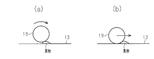
- (A) is a schematic diagram when a relay part rolls over a foreign substance
- (b) is a schematic diagram when a relay part slips and removes a foreign substance.
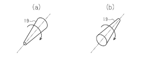
- (A), (b) is a perspective view which shows the relay part of another shape. Schematic which shows the foreign material inflow part of another example.
- the schematic diagram which shows the example of arrangement
- a rotary connector 1 for a vehicle is attached between a vehicle body 2 on a fixed side and a steering shaft 3 on a rotating side, and an electrical connection between the vehicle body 2 and the steering shaft 3. Is maintained even when the steering shaft 3 is rotated.
- the rotary connector 1 sends the output signal Sout of the detection unit 4 provided on the steering wheel (not shown) to the controller 5 on the vehicle body 2 side.
- the controller 5 includes an ECU (Electronic Control Unit) that manages the operation of the rotary connector 1 and determines the detection state of the detection unit 4 based on the acquired output signal Sout.
- ECU Electronic Control Unit
- the detection unit 4 includes, for example, a switch and a sensor disposed on the steering wheel.
- the output signal Sout is not limited to an on / off signal detected by, for example, a switch or a sensor, but may be a data signal detected by sensors such as an image sensor. Note that the output signal Sout may be a multiplexed signal in which signals output from the plurality of detection units 4 are collected in a time division manner and transmitted to the other party.
- the rotary connector 1 includes a fixed body 7 that is attached and fixed to the vehicle body 2 and a rotating body 8 that rotates with respect to the fixed body 7. Both the fixed body 7 and the rotating body 8 have a substantially disk shape and are disposed on the same axis (axis L1).
- the axis L1 is the rotational axis of the steering shaft 3.
- the stationary body 7 has a steering shaft 3 rotatably inserted through an insertion hole 11 formed at the center.
- the fixed body 7 includes a base material 12 made of a structure such as a resin and a conductive layer 13 that conducts electricity on the fixed body 7 side.
- the rotating body 8 includes a base material 15 made of a structure such as a resin and a conductive layer 16 that conducts electricity on the rotating body 8 side.
- the rotating body 8 has an insertion hole 14 formed in the center of the base material 15, and the steering shaft 3 is attached and fixed inside the insertion hole 14. When the steering shaft 3 is rotated, the rotating body 8 is supported by the fixed body 7 and rotates integrally with the steering shaft 3 around the axis L1.
- a relay unit 19 is provided between the fixed body 7 and the rotating body 8 to conduct electricity between the fixed body 7 and the rotating body 8.
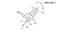
- the relay portion 19 of this example is formed in a cylindrical shape. That is, the relay unit 19 forms a cylindrical column whose two planes facing each other are congruent or non-congruent, so that the axial direction of the relay unit 19 (the length of the axis L2 shown in FIGS. 2 and 3). Direction), one end (point A in FIG. 3) is a rolling part to maintain wear resistance, and the other end (point B in FIG. 3) is a sliding part to improve foreign matter removal. Has been.
- the relay unit 19 is arranged so that its own axis L ⁇ b> 2 is along the radial direction of the rotating body 8, and in the rotating direction of the rotating body 8 (in the direction of arrow R in FIG. 1). A plurality of them are arranged at equal intervals along. In this way, the plurality of relay portions 19 are arranged radially with the center P of the rotary connector 1 as the center.
- the relay part 19 is individually accommodated in the accommodating part 20 provided in the base material 12 so that rotation and sliding are possible.
- the conductive layer 13 on the fixed body 7 side is arranged in a ring shape along the relay portion 19 arranged along the rotating direction of the rotating body 8. Further, in the rotary connector 1, one signal channel is constructed by a plurality of relay units 19 arranged on the same circumference around the center P.
- the operation and effect of the rotary connector 1 will be described with reference to FIGS.
- the rotating body 8 when the steering shaft 3 (steering wheel) is operated, the rotating body 8 also rotates synchronously, and the relay portion 19 rotates between the fixed body 7 and the rotating body 8. And slide.
- the relay portion 19 turns with the radially inner end 19a (hereinafter referred to as point A) as a support point.
- the relay portion 19 when the rotating body 8 rotates, the relay portion 19 has a point A that is the radially inner end 19 a and a radially outer end due to the difference in distance from the center P of the rotary connector 1.
- the circumferential distance required at the time of rotation differs between the portion 19b (hereinafter referred to as point B).
- point B the portion 19b
- the point A of the relay unit 19 when the point A of the relay unit 19 is used as a support point, when the point A of the relay unit 19 rotates three times, the point B of the relay unit 19 requires six rotations due to the difference in the circumferential distance of rotation. Actually, only three rotations that are the same as the number of rotations of the point A, which is the support point, can be performed.
- the relay portion 19 when the rotary connector 1 is rotated, the relay portion 19 is slid while the radially inner end 19a (point A) is rotated and the radially outer end 19b (point B) is rotated. To do.
- the relay portion 19 since the relay portion 19 has a cylindrical shape, the relay portion 19 can have a rolling portion and a sliding portion when the rotary connector 1 is rotated. For this reason, while maintaining abrasion resistance in the rolling part as before, foreign matter removal property is improved by the sliding part. Therefore, reliability in the rotary connector 1 can be improved.
- the relay unit 19 since the relay unit 19 makes line contact with the conductive layers 13 and 16 instead of point contact, the energization current can be increased. If the energization current of the relay unit 19 can be increased, this also leads to a reduction in the size of the rotary connector 1.
- the relay part 19 may be slid at the point A, and by sliding the relay part 19 at the point A and rotating at the point B, the wear resistance with the conductive layer 13 and the removal of foreign matters. Both sexes can be achieved.
- the relay part 19 is not limited to a column shape, It is also as a taper shape (cylindrical column body from which two opposing planes became noncongruent). Good.
- the example of FIGS. 7A and 7B has a shape without the tip of the cone.
- FIG. 7A shows an example in which the smaller cone diameter side is used as a support point for rotation
- FIG. 7B shows an example in which the larger cone diameter side is used as a support point for rotation. is there. In any case, it is possible to achieve both wear resistance and foreign matter removability.
- the relay unit 19 is arranged in a direction that causes its own axis L ⁇ b> 2 to run along the radial direction of the rotating body 8. Therefore, since the relay unit 19 is arranged in an optimum direction for rolling, it is advantageous to obtain a smooth rotation of the rotating body 8.
- a plurality of relaying sections 19 are arranged along the rotating direction of the rotating body 8 (the direction of the arrow R in FIG. 1). Therefore, it is possible to increase the number of energization points by the relay unit 19, which is more advantageous for increasing the energization current.
- the relay portion 19 is formed in a cylindrical shape or a tapered shape. Therefore, since it becomes possible to make the relay part 19 into the shape which is easy to roll, it becomes still more advantageous to obtain the smooth rotation of the rotary body 8.
- FIG. 1 A schematic diagram of a relay part 19 .
- the embodiment is not limited to the configuration described so far, and may be modified as follows.
- you may provide the foreign material inflow part 31 for the foreign material removed by the relay part 19 to enter into the inner wall of the accommodating part 20.
- the foreign matter removed by the relaying portion 19 can be collected in the foreign matter inflow portion 31, which is advantageous for maintaining good energization.
- the relay unit 19 is not limited to constructing only one channel, but may construct a plurality of channels.
- the figure is an example of two channels, and a group of relaying portions 19r arranged on the same circumference inside the rotary connector 1 on the same circumference forms the same channel, and on the same circumference outside the rotary connector 1 in the radial direction.
- the relay section 19s lined up in (1) constructs another channel.
- the rotary connector 1 can transmit signals of a plurality of channels.
- the wiring constructed by the relay unit 19 is not limited to the signal line for data transfer, but may be a control line for controlling the device or a power supply line for supplying power to the device.
- the relay part 19 provided with two or more is not limited to the same shape altogether, The thing of a different shape may be included.
- the number of relay units 19 is not limited to a plurality and may be only one. -The shape of the relay part 19 may be either bottomed or bottomless. -The rotation connector 1 is not limited to being applied to a vehicle, You may use it for another apparatus and apparatus.
Landscapes
- Steering Controls (AREA)
Abstract
回転コネクタ(1)は、固定体(7)と、固定体に対して回動可能な回動体(8)との間に配置された継電部(19)を備える。継電部(19)は、回動体の回動を許容した上で固定部と回動体との間の電気的な接続を維持する。継電部(19)は、対向する2平面が合同又は非合同となった筒状の柱体をなすことにより、継電部の軸方向の両端部のうちの一端部が転がり部分として機能し、他端部が滑り部分として機能する。
Description
本発明は、固定体及び回動体の間の通信を向上する回転コネクタに関する。
従来、一方が他方に対して回転する2部品の間の電気的な通電を維持する回転コネクタとして、ステアリングロールコネクタが広く知られている。この種のステアリングロールコネクタには、例えば固定体と回動体との間の継電部分に球体を使用するものが周知である(特許文献1等)。
しかし、特許文献1は、継電部分の球体が導体に点接触する構造をとっている。このため、球体及び導体の間に異物が存在したとき、回動体の回動時、球体が異物を乗り上げる動きをとってしまい、異物がその場に留まることになってしまう。よって、信頼性の点で問題があった。
本発明の目的は、異物除去の性能を向上して信頼性を向上することができる回転コネクタを提供することにある。
一態様の回転コネクタは、固定体に対して回動可能な回動体と当該固定体との間の電気的な接続を、前記固定体及び前記回動体の間に配置された継電部により、前記回動体の回動を許容した上で維持する構成において、前記継電部は、対向する2平面が合同又は非合同となった筒状の柱体をなすことにより、前記継電部の軸方向の両端部のうちの一端部が転がり部分として機能し、他端部が滑り部分として機能する。
本構成によれば、固定体及び回動体の間の通電箇所となる継電部を、転がり部分と滑り部分とを持たせる形状とした。このため、従前通り転がり部分において耐摩耗性を維持しつつ、その上、滑り部分により異物除去性を向上することが可能となる。よって、回転コネクタの信頼性を高めることが可能となる。
前記回転コネクタにおいて、前記継電部は、自身の軸を前記回動体の径方向に沿わせる向きに配置されていることが好ましい。この構成によれば、継電部を転がりに最適な向きに配置するので、回動体のスムーズな回動を得るのに有利となる。
前記回転コネクタにおいて、前記継電部は、前記回動体の回動方向に沿って配置された複数の継電部のうちの一つであることが好ましい。この構成によれば、継電部による通電箇所を多くとることが可能となるので、通電電流を増やすのに一層有利となる。
前記回転コネクタにおいて、前記継電部は、円柱形状又はテーパ形状に形成されていることが好ましい。この構成によれば、継電部を転がり易い形状とすることが可能となるので、回動体のスムーズな回動を得るのに一層有利となる。
前記回転コネクタにおいて、前記固定体は、前記継電部により除去された異物が入り込む異物流入部を備えることが好ましい。この構成によれば、継電部により除去された異物を異物流入部に集めることが可能となるので、良好な通電を維持するのに有利となる。
前記継電部は、各継電部の軸が前記回動体の径方向に一致する向きで前記回動体の回動方向に沿って配置された複数の継電部のうちの一つとすることができる。この場合、前記固定体は、前記複数の継電部を個別に収容する複数の収納部を含むことが好ましい。この構成によれば、各収納部内において各継電部に転がり部分と滑り部分の機能を好適に付与することができる。
本発明によれば、異物除去の性能を向上して信頼性を高めることができる。
以下、回転コネクタの一実施形態を図1~図7に従って説明する。
図1に示すように、車両用の回転コネクタ1は、固定側となる車体2と回動側となるステアリングシャフト3との間に取り付けられ、車体2及びステアリングシャフト3の間の電気的な接続を、ステアリングシャフト3が回動されても維持するものである。回転コネクタ1は、ステアリングホイール(図示略)に設けられた検知部4の出力信号Soutを、車体2側のコントローラ5に送出する。コントローラ5は、回転コネクタ1の作動を管理するECU(Electronic Control Unit)からなり、取得した出力信号Soutを基に検知部4の検知状態を判断する。
図1に示すように、車両用の回転コネクタ1は、固定側となる車体2と回動側となるステアリングシャフト3との間に取り付けられ、車体2及びステアリングシャフト3の間の電気的な接続を、ステアリングシャフト3が回動されても維持するものである。回転コネクタ1は、ステアリングホイール(図示略)に設けられた検知部4の出力信号Soutを、車体2側のコントローラ5に送出する。コントローラ5は、回転コネクタ1の作動を管理するECU(Electronic Control Unit)からなり、取得した出力信号Soutを基に検知部4の検知状態を判断する。
検知部4は、例えばステアリングホイールに配設されたスイッチやセンサ等からなる。また、出力信号Soutは、例えばスイッチやセンサにより検出されたオンオフ信号に限らず、例えば画像センサ等のセンサ類が検出したデータ信号でもよい。なお、出力信号Soutは、複数の検知部4から出力される信号を時分割によりまとめて相手側に送信する多重信号でもよい。
回転コネクタ1は、車体2に取り付け固定される固定体7と、固定体7に対して回動する回動体8とを備える。固定体7及び回動体8は、ともに略円板形状をなし、同一軸心(軸L1)上に配置されている。軸L1は、ステアリングシャフト3の回動軸心である。
固定体7は、中心に形成された挿通孔11にステアリングシャフト3が回動可能に挿通されている。固定体7は、例えば樹脂等の構造体からなる基材12と、固定体7側において電気を通す導電層13とを備える。回動体8は、例えば樹脂等の構造体からなる基材15と、回動体8側において電気を通す導電層16とを備える。回動体8は、基材15の中心に挿通孔14が形成され、この挿通孔14の内部にステアリングシャフト3が取り付け固定されている。ステアリングシャフト3が回動操作されたとき、回動体8は、固定体7に支持されてステアリングシャフト3と軸L1回りに一体回動する。
図1~図3に示すように、固定体7及び回動体8の間には、固定体7及び回動体8の間の通電を行う継電部19が設けられている。特に、図3に示すように、本例の継電部19は、円柱形状に形成されている。すなわち、継電部19は、対向する2平面が合同又は非合同となった筒状の柱体をなすことにより、継電部19の軸方向(図2及び図3で示す軸L2の長さ方向)の両端部のうち一端部(図3のA点)が転がり部分となって耐摩耗性が維持され、他端部(図3のB点)が滑り部分となって異物除去性が向上されている。
図2に示すように、継電部19は、自身の軸L2を回動体8の径方向に沿わせるように配置されるとともに、回動体8の回動方向(図1の矢印R方向)に沿って等間隔に複数配置されている。このように、複数の継電部19は、回転コネクタ1の中心Pを中央にして放射状に配置されている。継電部19は、基材12に設けられた収納部20に回動及び摺動可能に個別に収納されている。なお、固定体7側の導電層13は、回動体8の回動方向に沿って配置される継電部19に沿って環状に配置されている。また、回転コネクタ1は、中心P回りの同一円周上に配置された複数の継電部19により、信号の1チャンネルが構築される。
次に、図3~図7を用いて、回転コネクタ1の作用及び効果を説明する。
図3に示すように、ステアリングシャフト3(ステアリングホイール)が操作されると、これに伴って回動体8も同期回動し、継電部19が固定体7及び回動体8の間で回動及び摺動する。なお、本例の場合、径方向内側端部19a(以降、A点と記す)を支持点として、継電部19が回ることとする。
図3に示すように、ステアリングシャフト3(ステアリングホイール)が操作されると、これに伴って回動体8も同期回動し、継電部19が固定体7及び回動体8の間で回動及び摺動する。なお、本例の場合、径方向内側端部19a(以降、A点と記す)を支持点として、継電部19が回ることとする。
図4に示すように、回動体8が回転したときには、回転コネクタ1の中心Pからの距離の違いから、継電部19においては、径方向内側端部19aであるA点と径方向外側端部19b(以降、B点と記す)とで、回転時に必要となる周方向距離が異なる。例えば、継電部19のA点を支持点とした場合、継電部19のA点が3回転したときには、回転の周方向距離の違いから継電部19のB点では6回転必要なところ、実際には支持点であるA点の回転数と同じ3回転しかできないので、その分、B点において継電部19が摺動することとなる。このように、回転コネクタ1の回動時、継電部19は、径方向内側端部19a(A点)が回動し、径方向外側端部19b(B点)が回動しつつ摺動する。
図5(a)に示すように、継電部19が回動したとき、導電層13に異物が付着している場合、転がりは導電層13上の異物に乗り上げて回動するため摩耗に強い反面、継電部19が異物に乗り上げてしまうので、異物を除去する性能は低い。一方、図5(b)に示すように、継電部19が摺動したとき、滑りは導電層13との摩耗に弱い反面、導電層13に付着した異物をしっかりと除去することが可能である。
以上のように、本例の場合、継電部19を円柱形状としたので、回転コネクタ1の回動時、継電部19において転がり部分と滑り部分とを持たせることが可能となる。このため、従前通り転がり部分において耐摩耗性を維持しつつ、その上、滑り部分により異物除去性が向上される。よって、回転コネクタ1において信頼性を高めることができる。また、継電部19が導電層13,16に対して点接触ではなく線接触するので、通電電流を増やすこともできる。継電部19の通電電流を増やすことが可能となれば、これは回転コネクタ1の小型化にも繋がる。
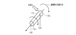
なお、図6に示すように、継電部19の径方向外側端部19b(B点)を支持点としてもよい。この場合、回転コネクタ1が回動するときのA点の回動距離が不足するので、継電部19がA点において多回転して摺動する。このように、継電部19はA点で摺動するものでもよく、継電部19をA点で摺動させ、B点で回転させることにより、導電層13との耐摩耗性及び異物除去性の両方を両立することができる。
また、図7(a),(b)に示すように、継電部19は、円柱形状に限定されず、テーパ形状(対向する2平面が非合同となった筒状の柱体)としてもよい。図7(a)、(b)の例は、円錐の先端をなくした形状である。また、図7(a)は、円錐の径の小さい側を回動の支持点とした例であり、図7(b)は、円錐の径の大きい側を回動の支持点とした例である。いずれにせよ、耐摩耗性及び異物除去性の両立が可能である。
継電部19は、自身の軸L2を回動体8の径方向に沿わせる向きに配置されている。よって、継電部19を転がりに最適な向きに配置するので、回動体8のスムーズな回動を得るのに有利となる。
継電部19は、回動体8の回動方向(図1の矢印R方向)に沿って複数配置されている。よって、継電部19による通電箇所を多くとることが可能となるので、通電電流を増やすのに一層有利となる。
継電部19は、円柱形状又はテーパ形状に形成されている。よって、継電部19を転がり易い形状とすることが可能となるので、回動体8のスムーズな回動を得るのに一層有利となる。
なお、実施形態はこれまでに述べた構成に限らず、以下の態様に変更してもよい。
・図8に示すように、収納部20の内壁に、継電部19により除去された異物が入り込むための異物流入部31を設けてもよい。この場合、継電部19により除去された異物を異物流入部31に集めることが可能となるので、良好な通電を維持するのに有利となる。
・図8に示すように、収納部20の内壁に、継電部19により除去された異物が入り込むための異物流入部31を設けてもよい。この場合、継電部19により除去された異物を異物流入部31に集めることが可能となるので、良好な通電を維持するのに有利となる。
・図9に示すように、継電部19は、1チャンネルのみ構築することに限らず、複数チャンネルを構築してもよい。同図は、2チャンネルの例であり、回転コネクタ1の径方向内側の同一円周上に並ぶ継電部19rの群が同一チャンネルを構築し、回転コネクタ1の径方向外側の同一円周上に並ぶ継電部19sが他のチャンネルを構築する。この場合、回転コネクタ1において複数チャンネルの信号を伝送することができる。
・継電部19が構築する配線は、データ転送のための信号線に限らず、機器を制御するための制御線や、機器に電力を供給する電源線としてもよい。
・複数設けられる継電部19は、全て同一形状に限定されず、異なる形状のものを含んでいてもよい。
・複数設けられる継電部19は、全て同一形状に限定されず、異なる形状のものを含んでいてもよい。
・継電部19の個数は、複数に限らず、1つのみとしてもよい。
・継電部19の形状は、有底、無底のどちらでもよい。
・回転コネクタ1は、車両に適用されることに限定されず、他の機器や装置に使用してもよい。
・継電部19の形状は、有底、無底のどちらでもよい。
・回転コネクタ1は、車両に適用されることに限定されず、他の機器や装置に使用してもよい。
Claims (6)
- 固定体に対して回動可能な回動体と当該固定体との間の電気的な接続を、前記固定体及び前記回動体の間に配置された継電部により、前記回動体の回動を許容した上で維持する回転コネクタにおいて、
前記継電部は、対向する2平面が合同又は非合同となった筒状の柱体をなすことにより、前記継電部の軸方向の両端部のうちの一端部が転がり部分として機能し、他端部が滑り部分として機能する
ことを特徴とする回転コネクタ。 - 前記継電部は、自身の軸を前記回動体の径方向に沿わせる向きに配置されている
請求項1に記載の回転コネクタ。 - 前記継電部は、前記回動体の回動方向に沿って配置された複数の継電部のうちの一つである
請求項1又は2に記載の回転コネクタ。 - 前記継電部は、円柱形状又はテーパ形状に形成されている
請求項1~3のうちいずれか一項に記載の回転コネクタ。 - 前記固定体は、前記継電部により除去された異物が入り込む異物流入部を備える
請求項1~4のうちいずれか一項に記載の回転コネクタ。 - 前記継電部は、各継電部の軸が前記回動体の径方向に一致する向きで前記回動体の回動方向に沿って配置された複数の継電部のうちの一つであり、
前記固定体は、前記複数の継電部を個別に収容する複数の収納部を含む、
請求項1~5のうちいずれか一項に記載の回転コネクタ。
Applications Claiming Priority (2)
| Application Number | Priority Date | Filing Date | Title |
|---|---|---|---|
| JP2016132508A JP2018006185A (ja) | 2016-07-04 | 2016-07-04 | 回転コネクタ |
| JP2016-132508 | 2016-07-04 |
Publications (1)
| Publication Number | Publication Date |
|---|---|
| WO2018008375A1 true WO2018008375A1 (ja) | 2018-01-11 |
Family
ID=60912797
Family Applications (1)
| Application Number | Title | Priority Date | Filing Date |
|---|---|---|---|
| PCT/JP2017/022484 Ceased WO2018008375A1 (ja) | 2016-07-04 | 2017-06-19 | 回転コネクタ |
Country Status (2)
| Country | Link |
|---|---|
| JP (1) | JP2018006185A (ja) |
| WO (1) | WO2018008375A1 (ja) |
Cited By (2)
| Publication number | Priority date | Publication date | Assignee | Title |
|---|---|---|---|---|
| AT522792B1 (de) * | 2019-11-20 | 2021-02-15 | Cutpack Com Gmbh | Elektrische Kontaktanordnung |
| WO2022002360A1 (en) * | 2020-06-30 | 2022-01-06 | Merit Automotive Electronics Systems S.L.U. | Clockspring with rolling contacts |
Citations (4)
| Publication number | Priority date | Publication date | Assignee | Title |
|---|---|---|---|---|
| JPS60119878U (ja) * | 1984-01-24 | 1985-08-13 | 松下電工株式会社 | 電機子の給電装置 |
| US5775920A (en) * | 1995-09-01 | 1998-07-07 | Methode Electronics, Inc. | Rolling elastomer contact clockspring |
| JPH10321336A (ja) * | 1997-02-27 | 1998-12-04 | Raytheon Co | コンジットとボールを使用するロータリコネクタ |
| WO2002001682A1 (en) * | 2000-06-29 | 2002-01-03 | Damco Limited | Electrical connectors |
-
2016
- 2016-07-04 JP JP2016132508A patent/JP2018006185A/ja active Pending
-
2017
- 2017-06-19 WO PCT/JP2017/022484 patent/WO2018008375A1/ja not_active Ceased
Patent Citations (4)
| Publication number | Priority date | Publication date | Assignee | Title |
|---|---|---|---|---|
| JPS60119878U (ja) * | 1984-01-24 | 1985-08-13 | 松下電工株式会社 | 電機子の給電装置 |
| US5775920A (en) * | 1995-09-01 | 1998-07-07 | Methode Electronics, Inc. | Rolling elastomer contact clockspring |
| JPH10321336A (ja) * | 1997-02-27 | 1998-12-04 | Raytheon Co | コンジットとボールを使用するロータリコネクタ |
| WO2002001682A1 (en) * | 2000-06-29 | 2002-01-03 | Damco Limited | Electrical connectors |
Cited By (3)
| Publication number | Priority date | Publication date | Assignee | Title |
|---|---|---|---|---|
| AT522792B1 (de) * | 2019-11-20 | 2021-02-15 | Cutpack Com Gmbh | Elektrische Kontaktanordnung |
| AT522792A4 (de) * | 2019-11-20 | 2021-02-15 | Cutpack Com Gmbh | Elektrische Kontaktanordnung |
| WO2022002360A1 (en) * | 2020-06-30 | 2022-01-06 | Merit Automotive Electronics Systems S.L.U. | Clockspring with rolling contacts |
Also Published As
| Publication number | Publication date |
|---|---|
| JP2018006185A (ja) | 2018-01-11 |
Similar Documents
| Publication | Publication Date | Title |
|---|---|---|
| US8616897B2 (en) | Slip-ring unit | |
| CN107250586B (zh) | 用于滚动轴承的传感器装置和具有这种传感器装置的滚动轴承装置 | |
| CN102823083B (zh) | 旋转连接器装置 | |
| JP5955309B2 (ja) | 電動リニアアクチュエータ及びその電動モータ | |
| US10625764B2 (en) | Steering wheel assembly | |
| WO2018008375A1 (ja) | 回転コネクタ | |
| CN103287484B (zh) | 齿条驱动式电动助力转向装置 | |
| CN208035939U (zh) | 一种转向电动轮毂装置 | |
| JP2016178807A (ja) | 巻取装置 | |
| CN103490244B (zh) | 旋转连接器 | |
| JP2009152089A (ja) | 回転コネクタ装置 | |
| EP2928028A2 (en) | Slip ring | |
| JP2018110498A (ja) | 回転型差動変圧器 | |
| US8177567B2 (en) | Apparatus for signal and current transmission between end points which can move relative to one another | |
| CN104870299A (zh) | 侧支架的位置检测装置 | |
| JP5670539B2 (ja) | センサを備えたベアリングユニット | |
| CN208085922U (zh) | 一种电动车的内置传感器的中轴装置 | |
| CN101626190B (zh) | 圆筒型直线电机的防旋转装置及其方法 | |
| JP2015090310A5 (ja) | ||
| JP2015184249A (ja) | 冗長型vrシンクロの断線検出方法及び装置 | |
| JP2018045786A (ja) | 回転コネクタ | |
| JP2015087224A5 (ja) | ||
| JP2018045862A (ja) | 回転コネクタ | |
| JP2018045863A (ja) | 回転コネクタ | |
| ATE440395T1 (de) | Hoch- oder mittelspannungs-drehteil |
Legal Events
| Date | Code | Title | Description |
|---|---|---|---|
| 121 | Ep: the epo has been informed by wipo that ep was designated in this application |
Ref document number: 17823982 Country of ref document: EP Kind code of ref document: A1 |
|
| NENP | Non-entry into the national phase |
Ref country code: DE |
|
| 122 | Ep: pct application non-entry in european phase |
Ref document number: 17823982 Country of ref document: EP Kind code of ref document: A1 |