WO2018008336A1 - Capteur de gaz - Google Patents
Capteur de gaz Download PDFInfo
- Publication number
- WO2018008336A1 WO2018008336A1 PCT/JP2017/021660 JP2017021660W WO2018008336A1 WO 2018008336 A1 WO2018008336 A1 WO 2018008336A1 JP 2017021660 W JP2017021660 W JP 2017021660W WO 2018008336 A1 WO2018008336 A1 WO 2018008336A1
- Authority
- WO
- WIPO (PCT)
- Prior art keywords
- unit
- heater
- gas
- chamber
- sensor
- Prior art date
Links
- 238000010438 heat treatment Methods 0.000 claims abstract description 8
- 238000001514 detection method Methods 0.000 claims description 66
- 239000000470 constituent Substances 0.000 claims description 8
- 239000000919 ceramic Substances 0.000 description 29
- 239000000758 substrate Substances 0.000 description 17
- 239000002184 metal Substances 0.000 description 8
- 239000003566 sealing material Substances 0.000 description 6
- 239000000853 adhesive Substances 0.000 description 3
- 230000001070 adhesive effect Effects 0.000 description 3
- 238000009413 insulation Methods 0.000 description 3
- 238000007781 pre-processing Methods 0.000 description 3
- 238000012856 packing Methods 0.000 description 2
- 230000002093 peripheral effect Effects 0.000 description 2
- 239000002699 waste material Substances 0.000 description 2
- 239000004020 conductor Substances 0.000 description 1
- 230000002349 favourable effect Effects 0.000 description 1
- 239000012784 inorganic fiber Substances 0.000 description 1
- 229910044991 metal oxide Inorganic materials 0.000 description 1
- 150000004706 metal oxides Chemical class 0.000 description 1
- 238000012986 modification Methods 0.000 description 1
- 230000004048 modification Effects 0.000 description 1
- 239000004745 nonwoven fabric Substances 0.000 description 1
- 230000035699 permeability Effects 0.000 description 1
- 239000011347 resin Substances 0.000 description 1
- 229920005989 resin Polymers 0.000 description 1
- 239000004065 semiconductor Substances 0.000 description 1
- 239000007784 solid electrolyte Substances 0.000 description 1
Images


Classifications
-
- G—PHYSICS
- G01—MEASURING; TESTING
- G01N—INVESTIGATING OR ANALYSING MATERIALS BY DETERMINING THEIR CHEMICAL OR PHYSICAL PROPERTIES
- G01N33/00—Investigating or analysing materials by specific methods not covered by groups G01N1/00 - G01N31/00
- G01N33/0004—Gaseous mixtures, e.g. polluted air
- G01N33/0009—General constructional details of gas analysers, e.g. portable test equipment
- G01N33/0027—General constructional details of gas analysers, e.g. portable test equipment concerning the detector
- G01N33/0036—General constructional details of gas analysers, e.g. portable test equipment concerning the detector specially adapted to detect a particular component
-
- G—PHYSICS
- G01—MEASURING; TESTING
- G01N—INVESTIGATING OR ANALYSING MATERIALS BY DETERMINING THEIR CHEMICAL OR PHYSICAL PROPERTIES
- G01N27/00—Investigating or analysing materials by the use of electric, electrochemical, or magnetic means
- G01N27/02—Investigating or analysing materials by the use of electric, electrochemical, or magnetic means by investigating impedance
- G01N27/04—Investigating or analysing materials by the use of electric, electrochemical, or magnetic means by investigating impedance by investigating resistance
- G01N27/12—Investigating or analysing materials by the use of electric, electrochemical, or magnetic means by investigating impedance by investigating resistance of a solid body in dependence upon absorption of a fluid; of a solid body in dependence upon reaction with a fluid, for detecting components in the fluid
-
- G—PHYSICS
- G01—MEASURING; TESTING
- G01N—INVESTIGATING OR ANALYSING MATERIALS BY DETERMINING THEIR CHEMICAL OR PHYSICAL PROPERTIES
- G01N27/00—Investigating or analysing materials by the use of electric, electrochemical, or magnetic means
- G01N27/26—Investigating or analysing materials by the use of electric, electrochemical, or magnetic means by investigating electrochemical variables; by using electrolysis or electrophoresis
- G01N27/403—Cells and electrode assemblies
- G01N27/406—Cells and probes with solid electrolytes
- G01N27/4067—Means for heating or controlling the temperature of the solid electrolyte
-
- G—PHYSICS
- G01—MEASURING; TESTING
- G01N—INVESTIGATING OR ANALYSING MATERIALS BY DETERMINING THEIR CHEMICAL OR PHYSICAL PROPERTIES
- G01N27/00—Investigating or analysing materials by the use of electric, electrochemical, or magnetic means
- G01N27/26—Investigating or analysing materials by the use of electric, electrochemical, or magnetic means by investigating electrochemical variables; by using electrolysis or electrophoresis
- G01N27/403—Cells and electrode assemblies
- G01N27/406—Cells and probes with solid electrolytes
- G01N27/407—Cells and probes with solid electrolytes for investigating or analysing gases
- G01N27/4071—Cells and probes with solid electrolytes for investigating or analysing gases using sensor elements of laminated structure
-
- G—PHYSICS
- G01—MEASURING; TESTING
- G01N—INVESTIGATING OR ANALYSING MATERIALS BY DETERMINING THEIR CHEMICAL OR PHYSICAL PROPERTIES
- G01N33/00—Investigating or analysing materials by specific methods not covered by groups G01N1/00 - G01N31/00
- G01N33/0004—Gaseous mixtures, e.g. polluted air
- G01N33/0009—General constructional details of gas analysers, e.g. portable test equipment
- G01N33/0011—Sample conditioning
- G01N33/0014—Sample conditioning by eliminating a gas
-
- G—PHYSICS
- G01—MEASURING; TESTING
- G01N—INVESTIGATING OR ANALYSING MATERIALS BY DETERMINING THEIR CHEMICAL OR PHYSICAL PROPERTIES
- G01N27/00—Investigating or analysing materials by the use of electric, electrochemical, or magnetic means
- G01N27/02—Investigating or analysing materials by the use of electric, electrochemical, or magnetic means by investigating impedance
- G01N27/04—Investigating or analysing materials by the use of electric, electrochemical, or magnetic means by investigating impedance by investigating resistance
- G01N27/14—Investigating or analysing materials by the use of electric, electrochemical, or magnetic means by investigating impedance by investigating resistance of an electrically-heated body in dependence upon change of temperature
Definitions
- the present invention relates to a gas sensor that detects the concentration of a specific gas component contained in a gas to be measured.
- Patent Document 1 a gas sensor that detects the concentration of a specific gas component contained in a gas to be measured has been known.
- This gas sensor is configured so that a certain amount of atmospheric air as a gas to be measured is supplied into the chamber, and after performing a pretreatment for burning and removing a combustible gas such as CO in the chamber, the gas to be measured is used as a sensor element. And NOx concentration is detected.
- a heater is provided separately for each of a part for performing pre-processing for removing other gas that affects the concentration detection of a specific gas component and a sensor element for detecting the concentration of the specific gas component.
- the number of heaters increases and the gas sensor becomes larger or dissipates from each heater. There is a problem that wasteful heat increases and the power consumption of the heater also increases.
- an object of the present invention is to provide a gas sensor that can improve the detection accuracy of a specific gas component, and can realize downsizing and power saving.
- the gas sensor of the present invention is provided with a first chamber for introducing a gas to be measured therein, and a specific gas contained in the gas to be measured introduced into the first chamber.
- An adjustment unit that includes a concentration adjustment unit that changes the concentration of the component, and a second chamber for introducing the gas to be measured that has passed through the adjustment unit are provided therein, and according to the concentration of the specific gas component
- a sensor unit including a detection unit whose electrical characteristics change, a concentration adjustment unit, a single heater for heating the detection unit, and at least a part of the sensor unit and the outside of the adjustment unit
- Serial heaters, and, in the form of the said sensor unit heater respectively thermally coupled, the adjusting unit, the sensor unit, and, the heater is formed by integrally.
- both units need only be heated with a single heater, so that the gas sensor can be reduced in size and power consumption. Further, by heating the detection unit to the operating temperature with the heater, the specific gas component can be detected stably, and the detection accuracy of the specific gas component can be improved. Further, the gas to be measured whose concentration of the specific gas component is adjusted by the adjustment unit is introduced into the sensor unit through the gas flow pipe not including the heater, so that the gas to be measured is, for example, between the adjustment unit and the sensor unit. Inadvertent heating by the heater prevents the concentration from changing further. For this reason, the gas to be measured that has been processed by the adjustment unit can be introduced into the sensor unit, and the detection accuracy of the specific gas component can be further improved.
- the detection unit may be arranged. According to this gas sensor, since the concentration adjustment unit and the detection unit are arranged on both sides of the heater, the heat of the heater can be transmitted to the concentration adjustment unit and the detection unit without waste, and further power saving can be realized.
- the state in which the density adjustment unit is arranged on the first surface side of the heater may be that the density adjustment unit is arranged directly or indirectly via another member on the first surface of the heater.
- the state in which the detection unit is arranged on the second surface side is only required that the detection unit is arranged directly or indirectly through another member on the second surface of the heater.
- the gas sensor according to claim 2 wherein the detection unit is disposed on the second surface of the single heater, and the concentration adjusting unit is disposed on the first surface side of the heater via a heat insulating layer. May be. According to this gas sensor, even if a single heater is used, the detection unit can be maintained at the operating temperature satisfactorily, and the detection accuracy of the specific gas component can be improved.
- a part of a constituent member for constituting the first chamber of the adjustment unit and a part of a constituent member for constituting the second chamber of the sensor unit are as follows.
- the concentration adjusting unit is disposed on the surface of the common member facing the first chamber
- the detection unit is disposed on the surface of the common member facing the second chamber.
- the single heater may be interposed between the concentration adjusting unit and the common member, or between the detection unit and the common member. According to this gas sensor, the number of parts of the gas sensor can be reduced by a common member, and the gas sensor can be further downsized.
- the present invention it is possible to obtain a gas sensor that can improve the detection accuracy of a specific gas component and can realize downsizing and power saving.
- FIG. 2 is a cross-sectional view taken along line AA in FIG. It is a disassembled perspective view of the gas sensor which concerns on the 2nd Embodiment of this invention.
- FIG. 4 is a sectional view taken along line BB in FIG. 3.
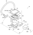
- FIG. 1 is an exploded perspective view of the gas sensor 1A according to the first embodiment of the present invention
- FIG. 2 is a cross-sectional view taken along the line AA in FIG.
- a gas sensor 1A includes an adjustment unit 10, a sensor unit 20, a pipe-shaped rubber tube (gas distribution tube) 40, and a plate-shaped ceramic wiring board 50, and is formed in a box shape as a whole. ing.
- the adjustment unit 10 has a substantially rectangular box shape with a flange and a metal case 12 having an open top surface (a surface facing upward in FIG. 1), and a rectangular frame-shaped sealing material (packing thereof) that contacts the flange of the case 12. ) 13, the concentration adjusting unit 14 accommodated in the case 12, and the ceramic wiring substrate 50. Then, the flange of the case 12 and the outer peripheral portion of the lower surface of the ceramic wiring substrate 50 are in contact with the frame of the sealing material 13, so that the ceramic substrate 50 closes the opening of the case 12 and the internal space of the case 12 is the first chamber.
- C1 is formed. Pipe-shaped inlets 12a and outlets 12b serving as piping connection ports protrude from the lower surface of the case 12 apart from each other, and the inlets 12a and outlets 12b communicate with the first chamber C1.
- a concentration adjusting unit 14 that is porous and allows gas to pass through is disposed, and a gap between the surface of the concentration adjusting unit 14 and the wall surface of the first chamber C1 is disposed.
- the sealing material 14a which seals is provided.
- the measured gas G introduced from the inlet 12a into the first chamber C1 comes into contact with the concentration adjusting unit 14 to adjust the concentration of the specific gas component, and is then discharged from the outlet 12b to the outside of the adjusting unit 10.
- the concentration adjusting unit 14 is a structure that functions to remove the miscellaneous gas different from the specific gas component and adjust the concentration of the specific gas component in the gas to be measured.
- the sensor unit 20 includes a metal case 22 having the same shape as the case 12 and an open bottom surface, and a rectangular frame-shaped sealing material (packing) 23 bonded to the flange of the case 22 via an adhesive (not shown). And a sensor element portion 24 accommodated in the case 22, a heat insulating sheet (heat insulating layer) 26 made of a non-woven fabric of inorganic fibers, and the ceramic wiring substrate 50.
- the flange of the case 22 and the outer peripheral portion of the upper surface of the ceramic wiring board 50 are fixed to the frame of the sealing material 23 via an adhesive (not shown), so that the opening of the case 22 is opened by the ceramic wiring board 50.
- the case 22 is closed, and the internal space of the case 22 forms the second chamber C2.
- the sensor element portion 24 has a substantially rectangular plate shape, and as shown in FIG. 2, a detection portion 24a is disposed on the upper surface (surface facing upward in FIG. 1) of the base portion 24c, and a heater is disposed on the lower surface side of the base portion 24c. 24b is disposed, and the detection unit 24a and the heater 24b are integrated with each other on the top and bottom of the base unit 24c.
- a concave portion 50r is formed in the center of the upper surface of the ceramic wiring substrate 50, the heat insulating sheet 26 is disposed in the concave portion 50r, and the sensor element portion 24 is disposed so that the heater 24b side is in contact with the upper surface of the heat insulating sheet 26.
- pipe-shaped inlets 22a and outlets 22b that serve as connection ports of the pipes are spaced apart from each other, and the inlets 22a and the outlets 22b communicate with the second chamber C2.
- the sensor element unit 24 is disposed in the recess 50r between the inlet 22a and the outlet 22b in the second chamber C2, and the inlet 22a is connected to the outlet 12b by a rubber tube 40. Then, the gas G to be measured whose concentration of the specific gas component is adjusted by passing through the adjustment unit 10 is introduced into the second chamber C2 from the inlet 22a through the rubber tube 40, and comes into contact with the detection unit 24a. After the concentration of the component is measured, the component is discharged from the outlet 22b to the outside of the sensor unit 20.
- the detection unit 24a detects the concentration of the specific gas component by detecting the electrical signal whose electrical characteristics change according to the concentration of the specific gas component and detecting the changed electrical signal.
- the heater 24b heats the detection unit 24a to the operating temperature by energization heating.
- the output terminal of the detection unit 24a and the energization terminal of the heater 24b are electrically connected to the ceramic wiring substrate 50 by wire bonding or the like.
- the base portion 24c can be configured using, for example, an insulating ceramic substrate.
- the detection part 24a can be comprised using a metal oxide semiconductor, for example.
- the heater 24b may be a circuit that is formed on the surface of the base portion 24c and serves as a heating resistor.
- the detection unit 24a may adopt a known configuration such as a configuration in which an electrode is provided on a solid electrolyte body.
- the end portion 50e (left side in FIG. 1) of the ceramic substrate 50 is narrower than the cases 12 and 22 and extends to the outside (left side in FIG. 1).
- a plurality of electrode pads 50p electrically connected to the part 24a and the heater 24b through the wire bonding and wiring (lead conductor) formed on the surface of the ceramic wiring substrate 50 are arranged.
- the electric signal output from the detection unit 24 is output to the outside through the electrode pad 50p of the ceramic wiring substrate 50, and the heater 24b is energized and heated by the electric power supplied from the outside through the electrode pad 50p.
- the sensor unit 20 and the heater 24 b are arranged such that the heater 24 b is stacked (contacted) with the detection unit 24 a and the base unit 24 c in the sensor unit 20. Thermally coupled like H1.
- the adjustment unit 10 and the heater 24b are stacked (contacted) with the heater 24b via the density adjustment unit 14 in the adjustment unit 10 through the heat insulating sheet 26 and the recessed portion 50r of the printed board 50.
- the sensor unit 20 and the heater 24b are thermally coupled means that any member constituting the sensor unit 20 and the heater 24b are coupled without interposing air (without a gap).
- a case where a heater separate from the detection unit 24 is thermally coupled to the case 22 constituting the sensor unit 20 and the space in the second chamber C2 is heated via the case 22 is also included.
- both units need only be heated by the single heater 24b, so that the gas sensor 1A can be reduced in size and power can be saved. .
- the detection unit 24a to the operating temperature by the heater 24b, the specific gas component can be detected stably, and the detection accuracy of the specific gas component can be improved.
- the gas G to be measured whose concentration of the specific gas component is adjusted by the adjustment unit 10 is introduced into the sensor unit 20 through the rubber tube 40 without the heater 24b interposed therebetween. The measured gas G is inadvertently heated by the heater, and the concentration does not change further. For this reason, the gas G to be measured that has been processed by the adjustment unit 10 can be introduced into the sensor unit 20, and the detection accuracy of the specific gas component can be further improved.
- the heater 24b is plate-shaped and has a lower surface (first surface) S1 and an upper surface (second surface) S2 that face each other.
- the density adjustment unit 14 is disposed on the S1 side
- the detection unit 24a is disposed on the upper surface S2 side.
- the density adjustment unit 14 and the detection unit 24a are respectively disposed on both surfaces of the heater 24b, so that the heat of the heater 24b can be transmitted to the density adjustment unit 14 and the detection unit 24a without waste, thereby further reducing power consumption. it can.
- the concentration adjusting unit 14 is disposed on the lower surface S1 side of the heater 24b via the heat insulating sheet 26. Thereby, even if it uses the single heater 24b, the detection part 24a can be maintained favorable to operating temperature.
- a part of the constituent members for configuring the first chamber C1 of the adjustment unit 10 and a part of the constituent members for configuring the second chamber C2 of the sensor unit 20 are as follows.
- the ceramic wiring board 50 is a common member.
- the concentration adjusting unit 14 is disposed on the surface side (lower surface) facing the first chamber C1 of the ceramic wiring substrate 50, and the detection unit 24a is disposed on the surface side (upper surface) facing the second chamber C2.
- the heater 24b is interposed between the detection unit 24a and the ceramic wiring board 50.
- the heat insulating sheet 26 is disposed between the heater 24 b and the ceramic wiring substrate 50.
- the heater 24b is arrange
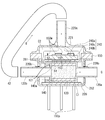
- FIGS. 3 is an exploded perspective view of the gas sensor 1B
- FIG. 4 is a cross-sectional view taken along the line BB of FIG.
- the gas sensor 1 ⁇ / b> B includes an adjustment unit 100, a sensor unit 200, and a rubber tube (gas flow tube) 42, and is formed in a box shape as a whole.
- the adjustment unit 100 has a substantially rectangular box shape with a metal first case 120 having one side surface (left side in FIG. 3) opened, and a lid-shaped metal second case 121 that closes the opening of the first case 120. And a concentration adjusting unit 140 accommodated in the first case 120.
- the internal space of the first case 120 closed by the second case 121 forms the first chamber C1.
- a pipe-like inlet 120a that serves as a connection port of the pipe projects.
- a pipe-shaped outlet 120b serving as a connection port for piping projects from the side surface of the second case 121 opposite to the first case 120.
- the inlet 120a and the outlet 120b communicate with the first chamber C1.
- the concentration adjusting unit 140 is disposed between the inlet 120a and the outlet 120b in the first chamber C1, and a sealing material 140a that seals a gap with the wall surface of the first chamber C1 is provided on the surface of the concentration adjusting unit 140.
- the concentration adjusting unit 140 is a structure that has gas permeability and functions to remove the miscellaneous gas different from the specific gas component and adjust the concentration of the specific gas component in the gas to be measured.
- the measured gas G introduced from the inlet 120a into the first chamber C1 comes into contact with the concentration adjusting unit 140 to adjust the concentration of the specific gas component, and is then discharged from the outlet 120b to the outside of the adjusting unit 100.
- the inside of the first case 120 is filled with the concentration adjusting unit 140, and the first chamber C ⁇ b> 1 is the internal space of the inlet 120 a in the first case 120. It is.
- the sensor unit 200 has a substantially rectangular box-like metal first case 220 having a flange and an open top surface, a lid-like metal second case 221 having a flange and an open bottom surface, and a rectangular frame shape.
- U-shaped notches (outlets) 220 b extending downward from the flanges are provided on opposite side surfaces of the first case 220.
- the adjustment unit 100 is arrange
- the ceramic wiring substrate 150 is disposed on the upper surface of the adjustment unit 100 (first case 120) via the heat insulating sheet 261, and the second case 221 is disposed on the ceramic wiring substrate 150. Then, the flanges of the first case 220 and the second case 221 are bonded to the frame body of the ceramic wiring substrate 150 via an adhesive (not shown), thereby opening the opening of the first case 220 to the second case 221.
- the inner space of the first case 220 and the second case 221 outside the adjustment unit 100 forms the second chamber C2.
- the sensor element unit 240 is suspended and fixed inside the frame of the ceramic wiring board 150 in the second chamber C2 by wire bonding 150w, protrudes below the ceramic wiring board 150, and is in contact with the heat insulating sheet 261.
- the sensor element unit 240 has a substantially rectangular plate shape and has the same structure as the sensor element unit 24 of the first embodiment. That is, as shown in FIG. 4, the detection part 240a is arrange
- the heater 240b is integrated with the base 240c. Since the detection part 240a and the heater 240b are the same structures as the detection part 24a and the heater 24b in 1st Embodiment, description is abbreviate
- the heater 240b is in contact with the heat insulating sheet 261.
- a pipe-like inlet 220a serving as a connection port for piping projects, and the inlet 220a communicates with the second chamber C2.
- the inlet 220a is connected to the outlet 120b by a rubber tube.
- the gas G to be measured whose concentration of the specific gas component has been adjusted by passing through the adjustment unit 100 is introduced from the inlet 220a into the second chamber C2 through the rubber tube 42, contacts the detection unit 240a, and the specific gas. After the concentration of the component is measured, it passes through the frame of the printed board 150 and is discharged from the notch 220b to the outside of the sensor unit 200.
- both notches 220b are larger than the outer diameters of the inlet 120a and the outlet 120b, respectively, and the gap between the notches 220b, the inlet 120a and the outlet 120b is an outlet.
- the output terminal of the detection unit 240a and the energization terminal of the heater 240b are electrically connected to the ceramic wiring substrate 150 by wire bonding 150w, and a plurality of electrical connections to the wire bonding 150w are provided below the ceramic wiring substrate 150.
- a pin-shaped terminal 150p protrudes.
- the electrical signal output from the detection unit 240a is output to the outside through the terminal 150p of the ceramic wiring board 150, and the heater 240b is energized and heated by the electric power supplied from the outside through the terminal 150p.
- the sensor unit 200 and the heater 240 b have an arrow indicating that the heater 240 b is stacked (contacted) with the detection unit 240 a and the base unit 240 c in the sensor unit 200. Thermally coupled like H1.
- the adjustment unit 100 and the heater 240b are configured such that the heater 240b is stacked (contacted) with the density adjustment unit 140 in the adjustment unit 100 via the heat insulating sheet 261 and the first case 120, so that the arrow It is thermally coupled like H2.
- the heater 240b is plate-shaped and has a lower surface (first surface) S1 and an upper surface (second surface) S2 that face each other.
- the density adjustment unit 140 is disposed on the S1 side, and the detection unit 240a is disposed on the upper surface S2 side. Also in the second embodiment, the density adjusting unit 140 is disposed on the lower surface S1 side of the heater 240b via the heat insulating sheet 261.
- the first case 120 (and the second case 121) is a common member.
- the concentration adjustment unit 140 is disposed on the surface side (lower surface) facing the first chamber C1 of the first case 120
- the detection unit 240a is disposed on the surface side (upper surface) facing the second chamber C2.
- the heater 240b is interposed between the detection unit 240a and the first case 120.
- the heat insulating sheet 261 is disposed between the heater 240 b and the first case 120.
- the gas sensor, the adjustment unit constituting the gas sensor, the shape of the sensor unit, and the like are not limited to the above embodiment.
- the types of the density adjustment unit and the detection unit are not limited.
- the gas distribution pipe is not limited to a rubber pipe, and a metal pipe, a resin pipe, a pipe obtained by connecting a metal pipe and a rubber pipe, or the like may be used.
Landscapes
- Chemical & Material Sciences (AREA)
- Health & Medical Sciences (AREA)
- Life Sciences & Earth Sciences (AREA)
- General Health & Medical Sciences (AREA)
- Immunology (AREA)
- Pathology (AREA)
- Analytical Chemistry (AREA)
- Biochemistry (AREA)
- Physics & Mathematics (AREA)
- General Physics & Mathematics (AREA)
- Engineering & Computer Science (AREA)
- Chemical Kinetics & Catalysis (AREA)
- Electrochemistry (AREA)
- Combustion & Propulsion (AREA)
- Food Science & Technology (AREA)
- Medicinal Chemistry (AREA)
- Molecular Biology (AREA)
- Investigating Or Analyzing Materials By The Use Of Electric Means (AREA)
- Investigating Or Analyzing Materials By The Use Of Fluid Adsorption Or Reactions (AREA)
Abstract
La présente invention concerne un capteur de gaz dans lequel la précision de détection d'un composant gazeux spécifique peut être améliorée et qui peut être miniaturisé et économiser de l'énergie. Un capteur de gaz 1A est pourvu de : une unité de réglage 10 comprenant une unité de réglage de concentration 14 qui modifie la concentration d'un composant gazeux spécifique contenu dans un gaz à mesurer G ayant été introduit dans une première chambre C1 ; une unité de capteur 20 comprenant une deuxième chambre C2 dans laquelle le gaz à mesurer ayant traversé l'unité de réglage est introduit, et comprenant une unité de détection 24a dont les caractéristiques électriques varient en fonction de la concentration du composant gazeux spécifique ; un dispositif de chauffage unique 24b pour chauffer l'unité de réglage de concentration et l'unité de détection ; et un tube de circulation de gaz en forme de tuyau 40 qui relie la première chambre et la deuxième chambre l'une à l'autre dans un état dans lequel au moins une partie du tube de circulation de gaz est disposée autour de l'extérieur de l'unité de réglage et autour de l'extérieur de l'unité de capteur, dans lequel l'unité de réglage, l'unité de capteur et le dispositif de chauffage sont intégrés les uns aux autres de sorte que l'unité de réglage et le dispositif de chauffage soient thermiquement couplés l'un à l'autre et l'unité de capteur et le dispositif de chauffage sont thermiquement couplés l'un à l'autre.
Priority Applications (2)
| Application Number | Priority Date | Filing Date | Title |
|---|---|---|---|
| US16/314,620 US20190227045A1 (en) | 2016-07-08 | 2017-06-12 | Gas sensor |
| EP17823943.0A EP3483596A4 (fr) | 2016-07-08 | 2017-06-12 | Capteur de gaz |
Applications Claiming Priority (2)
| Application Number | Priority Date | Filing Date | Title |
|---|---|---|---|
| JP2016135695A JP6635886B2 (ja) | 2016-07-08 | 2016-07-08 | ガスセンサ |
| JP2016-135695 | 2016-07-08 |
Publications (1)
| Publication Number | Publication Date |
|---|---|
| WO2018008336A1 true WO2018008336A1 (fr) | 2018-01-11 |
Family
ID=60912686
Family Applications (1)
| Application Number | Title | Priority Date | Filing Date |
|---|---|---|---|
| PCT/JP2017/021660 WO2018008336A1 (fr) | 2016-07-08 | 2017-06-12 | Capteur de gaz |
Country Status (4)
| Country | Link |
|---|---|
| US (1) | US20190227045A1 (fr) |
| EP (1) | EP3483596A4 (fr) |
| JP (1) | JP6635886B2 (fr) |
| WO (1) | WO2018008336A1 (fr) |
Cited By (2)
| Publication number | Priority date | Publication date | Assignee | Title |
|---|---|---|---|---|
| WO2018155119A1 (fr) * | 2017-02-21 | 2018-08-30 | 日本特殊陶業株式会社 | Capteur de gaz |
| WO2019235174A1 (fr) * | 2018-06-06 | 2019-12-12 | 日本特殊陶業株式会社 | Unité catalytique et capteur d'expiration |
Families Citing this family (6)
| Publication number | Priority date | Publication date | Assignee | Title |
|---|---|---|---|---|
| JP6635891B2 (ja) * | 2016-07-19 | 2020-01-29 | 日本特殊陶業株式会社 | ガスセンサ |
| WO2019138712A1 (fr) * | 2018-01-10 | 2019-07-18 | 日本特殊陶業株式会社 | Capteur de gaz |
| JP2019120641A (ja) * | 2018-01-10 | 2019-07-22 | 日本特殊陶業株式会社 | ガスセンサ |
| JP2019128325A (ja) * | 2018-01-26 | 2019-08-01 | 日本特殊陶業株式会社 | ガスセンサ |
| JP2019144135A (ja) * | 2018-02-21 | 2019-08-29 | 日本特殊陶業株式会社 | ガスセンサ |
| JP2019158824A (ja) * | 2018-03-16 | 2019-09-19 | 日本特殊陶業株式会社 | ガスセンサ |
Citations (2)
| Publication number | Priority date | Publication date | Assignee | Title |
|---|---|---|---|---|
| JPH10300702A (ja) * | 1997-04-24 | 1998-11-13 | Ngk Insulators Ltd | 低濃度NOx計測器 |
| JP2005214933A (ja) * | 2004-02-02 | 2005-08-11 | Shimadzu Corp | 水素センサ |
Family Cites Families (1)
| Publication number | Priority date | Publication date | Assignee | Title |
|---|---|---|---|---|
| JP2009533682A (ja) * | 2006-04-14 | 2009-09-17 | セラマテック・インク | 呼気中の窒素酸化物を測定する装置および方法 |
-
2016
- 2016-07-08 JP JP2016135695A patent/JP6635886B2/ja not_active Expired - Fee Related
-
2017
- 2017-06-12 US US16/314,620 patent/US20190227045A1/en not_active Abandoned
- 2017-06-12 WO PCT/JP2017/021660 patent/WO2018008336A1/fr unknown
- 2017-06-12 EP EP17823943.0A patent/EP3483596A4/fr not_active Withdrawn
Patent Citations (2)
| Publication number | Priority date | Publication date | Assignee | Title |
|---|---|---|---|---|
| JPH10300702A (ja) * | 1997-04-24 | 1998-11-13 | Ngk Insulators Ltd | 低濃度NOx計測器 |
| JP2005214933A (ja) * | 2004-02-02 | 2005-08-11 | Shimadzu Corp | 水素センサ |
Non-Patent Citations (1)
| Title |
|---|
| See also references of EP3483596A4 * |
Cited By (2)
| Publication number | Priority date | Publication date | Assignee | Title |
|---|---|---|---|---|
| WO2018155119A1 (fr) * | 2017-02-21 | 2018-08-30 | 日本特殊陶業株式会社 | Capteur de gaz |
| WO2019235174A1 (fr) * | 2018-06-06 | 2019-12-12 | 日本特殊陶業株式会社 | Unité catalytique et capteur d'expiration |
Also Published As
| Publication number | Publication date |
|---|---|
| EP3483596A1 (fr) | 2019-05-15 |
| JP6635886B2 (ja) | 2020-01-29 |
| EP3483596A4 (fr) | 2020-01-22 |
| JP2018004583A (ja) | 2018-01-11 |
| US20190227045A1 (en) | 2019-07-25 |
Similar Documents
| Publication | Publication Date | Title |
|---|---|---|
| WO2018008336A1 (fr) | Capteur de gaz | |
| CN108139254B (zh) | Mems流量传感器 | |
| JP5279667B2 (ja) | 熱式空気流量センサ | |
| KR102595005B1 (ko) | 분석 가스의 농도 측정용 가스 센서 | |
| JP2007212199A (ja) | センサのパッケージ構造及びこれを有するフローセンサ | |
| KR20080001673A (ko) | 대칭적으로 제공된 센서칩 및 압력도입통로를 구비한차압센서 | |
| WO2018096892A1 (fr) | Capteur de gaz | |
| KR101029168B1 (ko) | 라인 내부를 유동하는 공기의 매스를 측정하는 장치 | |
| JP2007163483A (ja) | 複数の成分を含むガス状流体における所定の成分を検出する方法およびセンサ | |
| CN111505061A (zh) | 气体传感器 | |
| WO2018110117A1 (fr) | Capteur d'expiration | |
| US20140216146A1 (en) | Air physical quantity sensing device | |
| CN104011536B (zh) | 具有空气压力测量装置的传感器元件 | |
| WO2018116641A1 (fr) | Capteur de gaz | |
| WO2018155119A1 (fr) | Capteur de gaz | |
| US20180275116A1 (en) | Gas sensor | |
| JP2018013355A (ja) | ガスセンサ | |
| JP3711597B2 (ja) | 空燃比検出装置 | |
| JP2020123065A (ja) | 流量制御装置 | |
| CN109073492A (zh) | 压力传感器装置 | |
| JP2019027881A (ja) | 測定装置 | |
| JP2013083282A (ja) | 流体機構及び該流体機構を構成する支持部材 | |
| JP2018531382A (ja) | 流動媒体の少なくとも1つの特性を検出するセンサ装置 | |
| JP2018531382A6 (ja) | 流動媒体の少なくとも1つの特性を検出するセンサ装置 | |
| JP2019168258A (ja) | ガスセンサ |
Legal Events
| Date | Code | Title | Description |
|---|---|---|---|
| 121 | Ep: the epo has been informed by wipo that ep was designated in this application |
Ref document number: 17823943 Country of ref document: EP Kind code of ref document: A1 |
|
| NENP | Non-entry into the national phase |
Ref country code: DE |
|
| ENP | Entry into the national phase |
Ref document number: 2017823943 Country of ref document: EP Effective date: 20190208 |