WO2018008336A1 - Gas sensor - Google Patents
Gas sensor Download PDFInfo
- Publication number
- WO2018008336A1 WO2018008336A1 PCT/JP2017/021660 JP2017021660W WO2018008336A1 WO 2018008336 A1 WO2018008336 A1 WO 2018008336A1 JP 2017021660 W JP2017021660 W JP 2017021660W WO 2018008336 A1 WO2018008336 A1 WO 2018008336A1
- Authority
- WO
- WIPO (PCT)
- Prior art keywords
- unit
- heater
- gas
- chamber
- sensor
- Prior art date
Links
Images


Classifications
-
- G—PHYSICS
- G01—MEASURING; TESTING
- G01N—INVESTIGATING OR ANALYSING MATERIALS BY DETERMINING THEIR CHEMICAL OR PHYSICAL PROPERTIES
- G01N33/00—Investigating or analysing materials by specific methods not covered by groups G01N1/00 - G01N31/00
- G01N33/0004—Gaseous mixtures, e.g. polluted air
- G01N33/0009—General constructional details of gas analysers, e.g. portable test equipment
- G01N33/0027—General constructional details of gas analysers, e.g. portable test equipment concerning the detector
- G01N33/0036—Specially adapted to detect a particular component
-
- G—PHYSICS
- G01—MEASURING; TESTING
- G01N—INVESTIGATING OR ANALYSING MATERIALS BY DETERMINING THEIR CHEMICAL OR PHYSICAL PROPERTIES
- G01N27/00—Investigating or analysing materials by the use of electric, electrochemical, or magnetic means
- G01N27/02—Investigating or analysing materials by the use of electric, electrochemical, or magnetic means by investigating impedance
- G01N27/04—Investigating or analysing materials by the use of electric, electrochemical, or magnetic means by investigating impedance by investigating resistance
- G01N27/12—Investigating or analysing materials by the use of electric, electrochemical, or magnetic means by investigating impedance by investigating resistance of a solid body in dependence upon absorption of a fluid; of a solid body in dependence upon reaction with a fluid, for detecting components in the fluid
-
- G—PHYSICS
- G01—MEASURING; TESTING
- G01N—INVESTIGATING OR ANALYSING MATERIALS BY DETERMINING THEIR CHEMICAL OR PHYSICAL PROPERTIES
- G01N27/00—Investigating or analysing materials by the use of electric, electrochemical, or magnetic means
- G01N27/26—Investigating or analysing materials by the use of electric, electrochemical, or magnetic means by investigating electrochemical variables; by using electrolysis or electrophoresis
- G01N27/403—Cells and electrode assemblies
- G01N27/406—Cells and probes with solid electrolytes
- G01N27/4067—Means for heating or controlling the temperature of the solid electrolyte
-
- G—PHYSICS
- G01—MEASURING; TESTING
- G01N—INVESTIGATING OR ANALYSING MATERIALS BY DETERMINING THEIR CHEMICAL OR PHYSICAL PROPERTIES
- G01N27/00—Investigating or analysing materials by the use of electric, electrochemical, or magnetic means
- G01N27/26—Investigating or analysing materials by the use of electric, electrochemical, or magnetic means by investigating electrochemical variables; by using electrolysis or electrophoresis
- G01N27/403—Cells and electrode assemblies
- G01N27/406—Cells and probes with solid electrolytes
- G01N27/407—Cells and probes with solid electrolytes for investigating or analysing gases
- G01N27/4071—Cells and probes with solid electrolytes for investigating or analysing gases using sensor elements of laminated structure
-
- G—PHYSICS
- G01—MEASURING; TESTING
- G01N—INVESTIGATING OR ANALYSING MATERIALS BY DETERMINING THEIR CHEMICAL OR PHYSICAL PROPERTIES
- G01N33/00—Investigating or analysing materials by specific methods not covered by groups G01N1/00 - G01N31/00
- G01N33/0004—Gaseous mixtures, e.g. polluted air
- G01N33/0009—General constructional details of gas analysers, e.g. portable test equipment
- G01N33/0011—Sample conditioning
- G01N33/0014—Sample conditioning by eliminating a gas
-
- G—PHYSICS
- G01—MEASURING; TESTING
- G01N—INVESTIGATING OR ANALYSING MATERIALS BY DETERMINING THEIR CHEMICAL OR PHYSICAL PROPERTIES
- G01N27/00—Investigating or analysing materials by the use of electric, electrochemical, or magnetic means
- G01N27/02—Investigating or analysing materials by the use of electric, electrochemical, or magnetic means by investigating impedance
- G01N27/04—Investigating or analysing materials by the use of electric, electrochemical, or magnetic means by investigating impedance by investigating resistance
- G01N27/14—Investigating or analysing materials by the use of electric, electrochemical, or magnetic means by investigating impedance by investigating resistance of an electrically-heated body in dependence upon change of temperature
Definitions
- the present invention relates to a gas sensor that detects the concentration of a specific gas component contained in a gas to be measured.
- Patent Document 1 a gas sensor that detects the concentration of a specific gas component contained in a gas to be measured has been known.
- This gas sensor is configured so that a certain amount of atmospheric air as a gas to be measured is supplied into the chamber, and after performing a pretreatment for burning and removing a combustible gas such as CO in the chamber, the gas to be measured is used as a sensor element. And NOx concentration is detected.
- a heater is provided separately for each of a part for performing pre-processing for removing other gas that affects the concentration detection of a specific gas component and a sensor element for detecting the concentration of the specific gas component.
- the number of heaters increases and the gas sensor becomes larger or dissipates from each heater. There is a problem that wasteful heat increases and the power consumption of the heater also increases.
- an object of the present invention is to provide a gas sensor that can improve the detection accuracy of a specific gas component, and can realize downsizing and power saving.
- the gas sensor of the present invention is provided with a first chamber for introducing a gas to be measured therein, and a specific gas contained in the gas to be measured introduced into the first chamber.
- An adjustment unit that includes a concentration adjustment unit that changes the concentration of the component, and a second chamber for introducing the gas to be measured that has passed through the adjustment unit are provided therein, and according to the concentration of the specific gas component
- a sensor unit including a detection unit whose electrical characteristics change, a concentration adjustment unit, a single heater for heating the detection unit, and at least a part of the sensor unit and the outside of the adjustment unit
- Serial heaters, and, in the form of the said sensor unit heater respectively thermally coupled, the adjusting unit, the sensor unit, and, the heater is formed by integrally.
- both units need only be heated with a single heater, so that the gas sensor can be reduced in size and power consumption. Further, by heating the detection unit to the operating temperature with the heater, the specific gas component can be detected stably, and the detection accuracy of the specific gas component can be improved. Further, the gas to be measured whose concentration of the specific gas component is adjusted by the adjustment unit is introduced into the sensor unit through the gas flow pipe not including the heater, so that the gas to be measured is, for example, between the adjustment unit and the sensor unit. Inadvertent heating by the heater prevents the concentration from changing further. For this reason, the gas to be measured that has been processed by the adjustment unit can be introduced into the sensor unit, and the detection accuracy of the specific gas component can be further improved.
- the detection unit may be arranged. According to this gas sensor, since the concentration adjustment unit and the detection unit are arranged on both sides of the heater, the heat of the heater can be transmitted to the concentration adjustment unit and the detection unit without waste, and further power saving can be realized.
- the state in which the density adjustment unit is arranged on the first surface side of the heater may be that the density adjustment unit is arranged directly or indirectly via another member on the first surface of the heater.
- the state in which the detection unit is arranged on the second surface side is only required that the detection unit is arranged directly or indirectly through another member on the second surface of the heater.
- the gas sensor according to claim 2 wherein the detection unit is disposed on the second surface of the single heater, and the concentration adjusting unit is disposed on the first surface side of the heater via a heat insulating layer. May be. According to this gas sensor, even if a single heater is used, the detection unit can be maintained at the operating temperature satisfactorily, and the detection accuracy of the specific gas component can be improved.
- a part of a constituent member for constituting the first chamber of the adjustment unit and a part of a constituent member for constituting the second chamber of the sensor unit are as follows.
- the concentration adjusting unit is disposed on the surface of the common member facing the first chamber
- the detection unit is disposed on the surface of the common member facing the second chamber.
- the single heater may be interposed between the concentration adjusting unit and the common member, or between the detection unit and the common member. According to this gas sensor, the number of parts of the gas sensor can be reduced by a common member, and the gas sensor can be further downsized.
- the present invention it is possible to obtain a gas sensor that can improve the detection accuracy of a specific gas component and can realize downsizing and power saving.
- FIG. 2 is a cross-sectional view taken along line AA in FIG. It is a disassembled perspective view of the gas sensor which concerns on the 2nd Embodiment of this invention.
- FIG. 4 is a sectional view taken along line BB in FIG. 3.
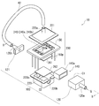
- FIG. 1 is an exploded perspective view of the gas sensor 1A according to the first embodiment of the present invention
- FIG. 2 is a cross-sectional view taken along the line AA in FIG.
- a gas sensor 1A includes an adjustment unit 10, a sensor unit 20, a pipe-shaped rubber tube (gas distribution tube) 40, and a plate-shaped ceramic wiring board 50, and is formed in a box shape as a whole. ing.
- the adjustment unit 10 has a substantially rectangular box shape with a flange and a metal case 12 having an open top surface (a surface facing upward in FIG. 1), and a rectangular frame-shaped sealing material (packing thereof) that contacts the flange of the case 12. ) 13, the concentration adjusting unit 14 accommodated in the case 12, and the ceramic wiring substrate 50. Then, the flange of the case 12 and the outer peripheral portion of the lower surface of the ceramic wiring substrate 50 are in contact with the frame of the sealing material 13, so that the ceramic substrate 50 closes the opening of the case 12 and the internal space of the case 12 is the first chamber.
- C1 is formed. Pipe-shaped inlets 12a and outlets 12b serving as piping connection ports protrude from the lower surface of the case 12 apart from each other, and the inlets 12a and outlets 12b communicate with the first chamber C1.
- a concentration adjusting unit 14 that is porous and allows gas to pass through is disposed, and a gap between the surface of the concentration adjusting unit 14 and the wall surface of the first chamber C1 is disposed.
- the sealing material 14a which seals is provided.
- the measured gas G introduced from the inlet 12a into the first chamber C1 comes into contact with the concentration adjusting unit 14 to adjust the concentration of the specific gas component, and is then discharged from the outlet 12b to the outside of the adjusting unit 10.
- the concentration adjusting unit 14 is a structure that functions to remove the miscellaneous gas different from the specific gas component and adjust the concentration of the specific gas component in the gas to be measured.
- the sensor unit 20 includes a metal case 22 having the same shape as the case 12 and an open bottom surface, and a rectangular frame-shaped sealing material (packing) 23 bonded to the flange of the case 22 via an adhesive (not shown). And a sensor element portion 24 accommodated in the case 22, a heat insulating sheet (heat insulating layer) 26 made of a non-woven fabric of inorganic fibers, and the ceramic wiring substrate 50.
- the flange of the case 22 and the outer peripheral portion of the upper surface of the ceramic wiring board 50 are fixed to the frame of the sealing material 23 via an adhesive (not shown), so that the opening of the case 22 is opened by the ceramic wiring board 50.
- the case 22 is closed, and the internal space of the case 22 forms the second chamber C2.
- the sensor element portion 24 has a substantially rectangular plate shape, and as shown in FIG. 2, a detection portion 24a is disposed on the upper surface (surface facing upward in FIG. 1) of the base portion 24c, and a heater is disposed on the lower surface side of the base portion 24c. 24b is disposed, and the detection unit 24a and the heater 24b are integrated with each other on the top and bottom of the base unit 24c.
- a concave portion 50r is formed in the center of the upper surface of the ceramic wiring substrate 50, the heat insulating sheet 26 is disposed in the concave portion 50r, and the sensor element portion 24 is disposed so that the heater 24b side is in contact with the upper surface of the heat insulating sheet 26.
- pipe-shaped inlets 22a and outlets 22b that serve as connection ports of the pipes are spaced apart from each other, and the inlets 22a and the outlets 22b communicate with the second chamber C2.
- the sensor element unit 24 is disposed in the recess 50r between the inlet 22a and the outlet 22b in the second chamber C2, and the inlet 22a is connected to the outlet 12b by a rubber tube 40. Then, the gas G to be measured whose concentration of the specific gas component is adjusted by passing through the adjustment unit 10 is introduced into the second chamber C2 from the inlet 22a through the rubber tube 40, and comes into contact with the detection unit 24a. After the concentration of the component is measured, the component is discharged from the outlet 22b to the outside of the sensor unit 20.
- the detection unit 24a detects the concentration of the specific gas component by detecting the electrical signal whose electrical characteristics change according to the concentration of the specific gas component and detecting the changed electrical signal.
- the heater 24b heats the detection unit 24a to the operating temperature by energization heating.
- the output terminal of the detection unit 24a and the energization terminal of the heater 24b are electrically connected to the ceramic wiring substrate 50 by wire bonding or the like.
- the base portion 24c can be configured using, for example, an insulating ceramic substrate.
- the detection part 24a can be comprised using a metal oxide semiconductor, for example.
- the heater 24b may be a circuit that is formed on the surface of the base portion 24c and serves as a heating resistor.
- the detection unit 24a may adopt a known configuration such as a configuration in which an electrode is provided on a solid electrolyte body.
- the end portion 50e (left side in FIG. 1) of the ceramic substrate 50 is narrower than the cases 12 and 22 and extends to the outside (left side in FIG. 1).
- a plurality of electrode pads 50p electrically connected to the part 24a and the heater 24b through the wire bonding and wiring (lead conductor) formed on the surface of the ceramic wiring substrate 50 are arranged.
- the electric signal output from the detection unit 24 is output to the outside through the electrode pad 50p of the ceramic wiring substrate 50, and the heater 24b is energized and heated by the electric power supplied from the outside through the electrode pad 50p.
- the sensor unit 20 and the heater 24 b are arranged such that the heater 24 b is stacked (contacted) with the detection unit 24 a and the base unit 24 c in the sensor unit 20. Thermally coupled like H1.
- the adjustment unit 10 and the heater 24b are stacked (contacted) with the heater 24b via the density adjustment unit 14 in the adjustment unit 10 through the heat insulating sheet 26 and the recessed portion 50r of the printed board 50.
- the sensor unit 20 and the heater 24b are thermally coupled means that any member constituting the sensor unit 20 and the heater 24b are coupled without interposing air (without a gap).
- a case where a heater separate from the detection unit 24 is thermally coupled to the case 22 constituting the sensor unit 20 and the space in the second chamber C2 is heated via the case 22 is also included.
- both units need only be heated by the single heater 24b, so that the gas sensor 1A can be reduced in size and power can be saved. .
- the detection unit 24a to the operating temperature by the heater 24b, the specific gas component can be detected stably, and the detection accuracy of the specific gas component can be improved.
- the gas G to be measured whose concentration of the specific gas component is adjusted by the adjustment unit 10 is introduced into the sensor unit 20 through the rubber tube 40 without the heater 24b interposed therebetween. The measured gas G is inadvertently heated by the heater, and the concentration does not change further. For this reason, the gas G to be measured that has been processed by the adjustment unit 10 can be introduced into the sensor unit 20, and the detection accuracy of the specific gas component can be further improved.
- the heater 24b is plate-shaped and has a lower surface (first surface) S1 and an upper surface (second surface) S2 that face each other.
- the density adjustment unit 14 is disposed on the S1 side
- the detection unit 24a is disposed on the upper surface S2 side.
- the density adjustment unit 14 and the detection unit 24a are respectively disposed on both surfaces of the heater 24b, so that the heat of the heater 24b can be transmitted to the density adjustment unit 14 and the detection unit 24a without waste, thereby further reducing power consumption. it can.
- the concentration adjusting unit 14 is disposed on the lower surface S1 side of the heater 24b via the heat insulating sheet 26. Thereby, even if it uses the single heater 24b, the detection part 24a can be maintained favorable to operating temperature.
- a part of the constituent members for configuring the first chamber C1 of the adjustment unit 10 and a part of the constituent members for configuring the second chamber C2 of the sensor unit 20 are as follows.
- the ceramic wiring board 50 is a common member.
- the concentration adjusting unit 14 is disposed on the surface side (lower surface) facing the first chamber C1 of the ceramic wiring substrate 50, and the detection unit 24a is disposed on the surface side (upper surface) facing the second chamber C2.
- the heater 24b is interposed between the detection unit 24a and the ceramic wiring board 50.
- the heat insulating sheet 26 is disposed between the heater 24 b and the ceramic wiring substrate 50.
- the heater 24b is arrange
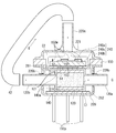
- FIGS. 3 is an exploded perspective view of the gas sensor 1B
- FIG. 4 is a cross-sectional view taken along the line BB of FIG.
- the gas sensor 1 ⁇ / b> B includes an adjustment unit 100, a sensor unit 200, and a rubber tube (gas flow tube) 42, and is formed in a box shape as a whole.
- the adjustment unit 100 has a substantially rectangular box shape with a metal first case 120 having one side surface (left side in FIG. 3) opened, and a lid-shaped metal second case 121 that closes the opening of the first case 120. And a concentration adjusting unit 140 accommodated in the first case 120.
- the internal space of the first case 120 closed by the second case 121 forms the first chamber C1.
- a pipe-like inlet 120a that serves as a connection port of the pipe projects.
- a pipe-shaped outlet 120b serving as a connection port for piping projects from the side surface of the second case 121 opposite to the first case 120.
- the inlet 120a and the outlet 120b communicate with the first chamber C1.
- the concentration adjusting unit 140 is disposed between the inlet 120a and the outlet 120b in the first chamber C1, and a sealing material 140a that seals a gap with the wall surface of the first chamber C1 is provided on the surface of the concentration adjusting unit 140.
- the concentration adjusting unit 140 is a structure that has gas permeability and functions to remove the miscellaneous gas different from the specific gas component and adjust the concentration of the specific gas component in the gas to be measured.
- the measured gas G introduced from the inlet 120a into the first chamber C1 comes into contact with the concentration adjusting unit 140 to adjust the concentration of the specific gas component, and is then discharged from the outlet 120b to the outside of the adjusting unit 100.
- the inside of the first case 120 is filled with the concentration adjusting unit 140, and the first chamber C ⁇ b> 1 is the internal space of the inlet 120 a in the first case 120. It is.
- the sensor unit 200 has a substantially rectangular box-like metal first case 220 having a flange and an open top surface, a lid-like metal second case 221 having a flange and an open bottom surface, and a rectangular frame shape.
- U-shaped notches (outlets) 220 b extending downward from the flanges are provided on opposite side surfaces of the first case 220.
- the adjustment unit 100 is arrange
- the ceramic wiring substrate 150 is disposed on the upper surface of the adjustment unit 100 (first case 120) via the heat insulating sheet 261, and the second case 221 is disposed on the ceramic wiring substrate 150. Then, the flanges of the first case 220 and the second case 221 are bonded to the frame body of the ceramic wiring substrate 150 via an adhesive (not shown), thereby opening the opening of the first case 220 to the second case 221.
- the inner space of the first case 220 and the second case 221 outside the adjustment unit 100 forms the second chamber C2.
- the sensor element unit 240 is suspended and fixed inside the frame of the ceramic wiring board 150 in the second chamber C2 by wire bonding 150w, protrudes below the ceramic wiring board 150, and is in contact with the heat insulating sheet 261.
- the sensor element unit 240 has a substantially rectangular plate shape and has the same structure as the sensor element unit 24 of the first embodiment. That is, as shown in FIG. 4, the detection part 240a is arrange
- the heater 240b is integrated with the base 240c. Since the detection part 240a and the heater 240b are the same structures as the detection part 24a and the heater 24b in 1st Embodiment, description is abbreviate
- the heater 240b is in contact with the heat insulating sheet 261.
- a pipe-like inlet 220a serving as a connection port for piping projects, and the inlet 220a communicates with the second chamber C2.
- the inlet 220a is connected to the outlet 120b by a rubber tube.
- the gas G to be measured whose concentration of the specific gas component has been adjusted by passing through the adjustment unit 100 is introduced from the inlet 220a into the second chamber C2 through the rubber tube 42, contacts the detection unit 240a, and the specific gas. After the concentration of the component is measured, it passes through the frame of the printed board 150 and is discharged from the notch 220b to the outside of the sensor unit 200.
- both notches 220b are larger than the outer diameters of the inlet 120a and the outlet 120b, respectively, and the gap between the notches 220b, the inlet 120a and the outlet 120b is an outlet.
- the output terminal of the detection unit 240a and the energization terminal of the heater 240b are electrically connected to the ceramic wiring substrate 150 by wire bonding 150w, and a plurality of electrical connections to the wire bonding 150w are provided below the ceramic wiring substrate 150.
- a pin-shaped terminal 150p protrudes.
- the electrical signal output from the detection unit 240a is output to the outside through the terminal 150p of the ceramic wiring board 150, and the heater 240b is energized and heated by the electric power supplied from the outside through the terminal 150p.
- the sensor unit 200 and the heater 240 b have an arrow indicating that the heater 240 b is stacked (contacted) with the detection unit 240 a and the base unit 240 c in the sensor unit 200. Thermally coupled like H1.
- the adjustment unit 100 and the heater 240b are configured such that the heater 240b is stacked (contacted) with the density adjustment unit 140 in the adjustment unit 100 via the heat insulating sheet 261 and the first case 120, so that the arrow It is thermally coupled like H2.
- the heater 240b is plate-shaped and has a lower surface (first surface) S1 and an upper surface (second surface) S2 that face each other.
- the density adjustment unit 140 is disposed on the S1 side, and the detection unit 240a is disposed on the upper surface S2 side. Also in the second embodiment, the density adjusting unit 140 is disposed on the lower surface S1 side of the heater 240b via the heat insulating sheet 261.
- the first case 120 (and the second case 121) is a common member.
- the concentration adjustment unit 140 is disposed on the surface side (lower surface) facing the first chamber C1 of the first case 120
- the detection unit 240a is disposed on the surface side (upper surface) facing the second chamber C2.
- the heater 240b is interposed between the detection unit 240a and the first case 120.
- the heat insulating sheet 261 is disposed between the heater 240 b and the first case 120.
- the gas sensor, the adjustment unit constituting the gas sensor, the shape of the sensor unit, and the like are not limited to the above embodiment.
- the types of the density adjustment unit and the detection unit are not limited.
- the gas distribution pipe is not limited to a rubber pipe, and a metal pipe, a resin pipe, a pipe obtained by connecting a metal pipe and a rubber pipe, or the like may be used.
Abstract
Provided is a gas sensor in which accuracy of sensing a specific gas component can be improved and which can be downsized and save power. A gas sensor 1A is provided with: an adjustment unit 10 including a concentration adjustment unit 14 which changes the concentration of a specific gas component contained in a to-be-measured gas G having been introduced into a first chamber C1; a sensor unit 20 including a second chamber C2 into which the to-be-measured gas having passed through the adjustment unit is introduced, and including a sensing unit 24a the electrical characteristics of which vary depending on the concentration of the specific gas component; a single heater 24b for heating the concentration adjustment unit and the sensing unit; and a pipe-shaped gas circulation tube 40 which connects the first chamber and the second chamber to each other in a state where at least a part of the gas circulation tube is laid around the outside of the adjustment unit and around the outside of the sensor unit, wherein the adjustment unit, the sensor unit, and the heater are integrated with one another such that the adjustment unit and the heater are thermally coupled with each other and the sensor unit and the heater are thermally coupled with each other.
Description
本発明は、被測定ガスに含まれる特定ガス成分の濃度を検知するガスセンサに関する。
The present invention relates to a gas sensor that detects the concentration of a specific gas component contained in a gas to be measured.
従来から、被測定ガスに含まれる特定ガス成分の濃度を検知するガスセンサが知られている(特許文献1)。
このガスセンサは、チャンバ内に被測定ガスとしての大気が一定量供給されるように構成され、チャンバ内でCO等の可燃性ガスを燃焼除去する前処理を行った後、被測定ガスをセンサ素子に接触させて、NOx濃度を検知している。 Conventionally, a gas sensor that detects the concentration of a specific gas component contained in a gas to be measured has been known (Patent Document 1).
This gas sensor is configured so that a certain amount of atmospheric air as a gas to be measured is supplied into the chamber, and after performing a pretreatment for burning and removing a combustible gas such as CO in the chamber, the gas to be measured is used as a sensor element. And NOx concentration is detected.
特許文献1では、特定ガス成分の濃度検知に影響を与える他のガスを除去するための前処理を行う部位と、特定ガス成分の濃度を検知するセンサ素子とにそれぞれ別個にヒータを設け、双方を加熱して前処理機能とセンシング機能を発揮させている。しかしながら、上記前処理機能のように特定ガス成分の濃度を変化させる機能と、センシング機能を発揮させるために別個にヒータを設置した場合、ヒータが増えてガスセンサが大型化したり、各ヒータから散逸する無駄な熱が増えてヒータの電力消費も増えるという問題がある。一方、特定ガス成分の検知精度を向上させるためには、少なくともガス検知部を動作温度以上に加熱する必要があり、ヒータを非設置とすることは現実的ではない。
そこで、本発明は、特定ガス成分の検知精度を向上させると共に、小型化及び省電力化を実現できるガスセンサを提供することを目的とする。 InPatent Document 1, a heater is provided separately for each of a part for performing pre-processing for removing other gas that affects the concentration detection of a specific gas component and a sensor element for detecting the concentration of the specific gas component. Is heated to demonstrate its pre-processing and sensing functions. However, when heaters are installed separately to perform the function of changing the concentration of a specific gas component, such as the pre-processing function, and the sensing function, the number of heaters increases and the gas sensor becomes larger or dissipates from each heater. There is a problem that wasteful heat increases and the power consumption of the heater also increases. On the other hand, in order to improve the detection accuracy of the specific gas component, it is necessary to heat at least the gas detection unit to the operating temperature or higher, and it is not realistic not to install the heater.
Therefore, an object of the present invention is to provide a gas sensor that can improve the detection accuracy of a specific gas component, and can realize downsizing and power saving.
そこで、本発明は、特定ガス成分の検知精度を向上させると共に、小型化及び省電力化を実現できるガスセンサを提供することを目的とする。 In
Therefore, an object of the present invention is to provide a gas sensor that can improve the detection accuracy of a specific gas component, and can realize downsizing and power saving.
上記課題を解決するため、本発明のガスセンサは、自身の内部に被測定ガスを導入するための第1チャンバが設けられるとともに、前記第1チャンバに導入された該被測定ガスに含まれる特定ガス成分の濃度を変化させる濃度調整部を備える調整ユニットと、自身の内部に前記調整ユニットを通過した前記被測定ガスを導入するための第2チャンバが設けられるとともに、前記特定ガス成分の濃度に応じて電気的特性が変化する検知部を備えるセンサユニットと、前記濃度調整部、及び、前記検知部を加熱するための単一のヒータと、少なくとも一部が前記調整ユニットの外部及び前記センサユニットの外部に引き回された状態で、前記第1チャンバと前記第2チャンバと連通させるパイプ状のガス流通管と、を備え、前記調整ユニットと前記ヒータ、及び、前記センサユニットと前記ヒータがそれぞれ熱結合する形態で、前記調整ユニット、前記センサユニット、及び、前記ヒータが一体化されてなる。
In order to solve the above problems, the gas sensor of the present invention is provided with a first chamber for introducing a gas to be measured therein, and a specific gas contained in the gas to be measured introduced into the first chamber. An adjustment unit that includes a concentration adjustment unit that changes the concentration of the component, and a second chamber for introducing the gas to be measured that has passed through the adjustment unit are provided therein, and according to the concentration of the specific gas component A sensor unit including a detection unit whose electrical characteristics change, a concentration adjustment unit, a single heater for heating the detection unit, and at least a part of the sensor unit and the outside of the adjustment unit A pipe-like gas flow pipe communicating with the first chamber and the second chamber in a state of being routed to the outside, and the adjustment unit; Serial heaters, and, in the form of the said sensor unit heater respectively thermally coupled, the adjusting unit, the sensor unit, and, the heater is formed by integrally.
このガスセンサによれば、調整ユニットとセンサユニットとにそれぞれ別個にヒータを設けた場合に比べ、単一のヒータで両ユニットを加熱すればよいので、ガスセンサの小型化及び省電力化を実現できる。又、検知部をヒータで動作温度に加熱することで、特定ガス成分を安定して検知でき、特定ガス成分の検知精度を向上させることができる。
さらに、調整ユニットで特定ガス成分の濃度が調整された被測定ガスは、ヒータが介在しないガス流通管を通ってセンサユニットに導入されるので、例えば調整ユニットとセンサユニットの間で被測定ガスが不用意にヒータで加熱され、濃度がさらに変化することが無い。このため、調整ユニットで処理された状態の被測定ガスをセンサユニットに導入することができ、特定ガス成分の検知精度をさらに向上させることができる。 According to this gas sensor, as compared with the case where the adjustment unit and the sensor unit are provided with separate heaters, both units need only be heated with a single heater, so that the gas sensor can be reduced in size and power consumption. Further, by heating the detection unit to the operating temperature with the heater, the specific gas component can be detected stably, and the detection accuracy of the specific gas component can be improved.
Further, the gas to be measured whose concentration of the specific gas component is adjusted by the adjustment unit is introduced into the sensor unit through the gas flow pipe not including the heater, so that the gas to be measured is, for example, between the adjustment unit and the sensor unit. Inadvertent heating by the heater prevents the concentration from changing further. For this reason, the gas to be measured that has been processed by the adjustment unit can be introduced into the sensor unit, and the detection accuracy of the specific gas component can be further improved.
請求項1に記載のガスセンサであって、前記単一のヒータは対向する第1面、第2面を有し、前記第1面側に前記濃度調整部が配置され、前記第2面側に前記検知部が配置されていてもよい。
このガスセンサによれば、ヒータの両面に濃度調整部及び検知部がそれぞれ配置されるので、ヒータの熱を濃度調整部及び検知部に無駄なく伝えることができ、省電力化をさらに実現できる。なお、ヒータの第1面側に濃度調整部が配置される状態は、濃度調整部がヒータの第1面に直接又は他部材を介して間接的に配置されていればよく、また、ヒータの第2面側に検知部が配置される状態は、検知部がヒータの第2面に直接又は他部材を介して間接的に配置されていればよいものである。 2. The gas sensor according toclaim 1, wherein the single heater has a first surface and a second surface facing each other, the concentration adjusting unit is disposed on the first surface side, and the second surface side is disposed on the second surface side. The detection unit may be arranged.
According to this gas sensor, since the concentration adjustment unit and the detection unit are arranged on both sides of the heater, the heat of the heater can be transmitted to the concentration adjustment unit and the detection unit without waste, and further power saving can be realized. The state in which the density adjustment unit is arranged on the first surface side of the heater may be that the density adjustment unit is arranged directly or indirectly via another member on the first surface of the heater. The state in which the detection unit is arranged on the second surface side is only required that the detection unit is arranged directly or indirectly through another member on the second surface of the heater.
このガスセンサによれば、ヒータの両面に濃度調整部及び検知部がそれぞれ配置されるので、ヒータの熱を濃度調整部及び検知部に無駄なく伝えることができ、省電力化をさらに実現できる。なお、ヒータの第1面側に濃度調整部が配置される状態は、濃度調整部がヒータの第1面に直接又は他部材を介して間接的に配置されていればよく、また、ヒータの第2面側に検知部が配置される状態は、検知部がヒータの第2面に直接又は他部材を介して間接的に配置されていればよいものである。 2. The gas sensor according to
According to this gas sensor, since the concentration adjustment unit and the detection unit are arranged on both sides of the heater, the heat of the heater can be transmitted to the concentration adjustment unit and the detection unit without waste, and further power saving can be realized. The state in which the density adjustment unit is arranged on the first surface side of the heater may be that the density adjustment unit is arranged directly or indirectly via another member on the first surface of the heater. The state in which the detection unit is arranged on the second surface side is only required that the detection unit is arranged directly or indirectly through another member on the second surface of the heater.
請求項2に記載のガスセンサであって、前記単一のヒータの前記第2面上に前記検知部が配置され、前記濃度調整部は断熱層を介して前記ヒータの前記第1面側に配置されていてもよい。
このガスセンサによれば、単一のヒータを用いても、検知部を動作温度に良好に維持することができ、特定ガス成分の検知精度を向上させることができる。 The gas sensor according to claim 2, wherein the detection unit is disposed on the second surface of the single heater, and the concentration adjusting unit is disposed on the first surface side of the heater via a heat insulating layer. May be.
According to this gas sensor, even if a single heater is used, the detection unit can be maintained at the operating temperature satisfactorily, and the detection accuracy of the specific gas component can be improved.
請求項1に記載のガスセンサであって、前記調整ユニットの前記第1チャンバを構成するための構成部材の一部と前記センサユニットの前記第2チャンバを構成するための構成部材の一部とは、共通の部材からなり、前記共通の部材の前記第1チャンバに臨む面側に前記濃度調整部が配置される一方、前記共通の部材の前記第2チャンバに臨む面側に前記検知部が配置され、前記単一のヒータは、前記濃度調整部と前記共通の部材との間、又は、前記検知部と前記共通の部材との間のいずれかに介在していてもよい。
このガスセンサによれば、共通の部材によってガスセンサの部品点数を削減できると共に、ガスセンサをより小型化できる。 2. The gas sensor according toclaim 1, wherein a part of a constituent member for constituting the first chamber of the adjustment unit and a part of a constituent member for constituting the second chamber of the sensor unit are as follows. And the concentration adjusting unit is disposed on the surface of the common member facing the first chamber, and the detection unit is disposed on the surface of the common member facing the second chamber. The single heater may be interposed between the concentration adjusting unit and the common member, or between the detection unit and the common member.
According to this gas sensor, the number of parts of the gas sensor can be reduced by a common member, and the gas sensor can be further downsized.
このガスセンサによれば、共通の部材によってガスセンサの部品点数を削減できると共に、ガスセンサをより小型化できる。 2. The gas sensor according to
According to this gas sensor, the number of parts of the gas sensor can be reduced by a common member, and the gas sensor can be further downsized.
請求項4に記載のガスセンサであって、前記単一のヒータは、前記検知部と前記共通の部材との間に介在し、前記ヒータと前記共通の部材との間に断熱層が配置されていてもよい。
このガスセンサによれば、ヒータが共通の部材よりも検知部側に配置されるので、ヒータによって検知部を迅速に動作温度に加熱でき、特定ガス成分の検知精度をさらに向上させることができる。 5. The gas sensor according to claim 4, wherein the single heater is interposed between the detection unit and the common member, and a heat insulating layer is disposed between the heater and the common member. May be.
According to this gas sensor, since the heater is disposed closer to the detection unit than the common member, the detection unit can be quickly heated to the operating temperature by the heater, and the detection accuracy of the specific gas component can be further improved.
この発明によれば、特定ガス成分の検知精度を向上させると共に、小型化及び省電力化を実現できるガスセンサが得られる。
According to the present invention, it is possible to obtain a gas sensor that can improve the detection accuracy of a specific gas component and can realize downsizing and power saving.
以下に、本発明を、図面を参照しながら詳細に説明する。図1は、本発明の第1の実施形態におけるガスセンサ1Aの分解斜視図、図2は図1のA-A線に沿う断面図である。
図1において、ガスセンサ1Aは、調整ユニット10と、センサユニット20と、パイプ状のゴム管(ガス流通管)40と、板状のセラミック配線基板50と、を備え、全体として箱状に形成されている。 Hereinafter, the present invention will be described in detail with reference to the drawings. FIG. 1 is an exploded perspective view of thegas sensor 1A according to the first embodiment of the present invention, and FIG. 2 is a cross-sectional view taken along the line AA in FIG.
In FIG. 1, agas sensor 1A includes an adjustment unit 10, a sensor unit 20, a pipe-shaped rubber tube (gas distribution tube) 40, and a plate-shaped ceramic wiring board 50, and is formed in a box shape as a whole. ing.
図1において、ガスセンサ1Aは、調整ユニット10と、センサユニット20と、パイプ状のゴム管(ガス流通管)40と、板状のセラミック配線基板50と、を備え、全体として箱状に形成されている。 Hereinafter, the present invention will be described in detail with reference to the drawings. FIG. 1 is an exploded perspective view of the
In FIG. 1, a
調整ユニット10は、略矩形箱状でフランジを有し上面(図1の上方に向く面)が開口する金属製のケース12と、ケース12のフランジに当接する矩形枠状のシール材(のパッキン)13と、ケース12内に収容される濃度調整部14と、上記セラミック配線基板50と、を有している。そして、シール材13の枠体にケース12のフランジ及びセラミック配線基板50の下面の外周部分が当接することで、ケース12の開口をセラミック基板50が閉塞し、ケース12の内部空間が第1チャンバC1を形成する。
ケース12の下面には、配管の接続口となるパイプ状のインレット12a及びアウトレット12bがそれぞれ離間して突出しており、インレット12a及びアウトレット12bは第1チャンバC1に連通している。 Theadjustment unit 10 has a substantially rectangular box shape with a flange and a metal case 12 having an open top surface (a surface facing upward in FIG. 1), and a rectangular frame-shaped sealing material (packing thereof) that contacts the flange of the case 12. ) 13, the concentration adjusting unit 14 accommodated in the case 12, and the ceramic wiring substrate 50. Then, the flange of the case 12 and the outer peripheral portion of the lower surface of the ceramic wiring substrate 50 are in contact with the frame of the sealing material 13, so that the ceramic substrate 50 closes the opening of the case 12 and the internal space of the case 12 is the first chamber. C1 is formed.
Pipe-shaped inlets 12a and outlets 12b serving as piping connection ports protrude from the lower surface of the case 12 apart from each other, and the inlets 12a and outlets 12b communicate with the first chamber C1.
ケース12の下面には、配管の接続口となるパイプ状のインレット12a及びアウトレット12bがそれぞれ離間して突出しており、インレット12a及びアウトレット12bは第1チャンバC1に連通している。 The
Pipe-
第1チャンバC1におけるインレット12aとアウトレット12bとの間に、多孔質状をなしガスを透過可能な濃度調整部14が配置され、濃度調整部14の表面には第1チャンバC1の壁面との隙間をシールするシール材14aが設けられている。
そして、インレット12aから第1チャンバC1に導入された被測定ガスGが濃度調整部14に接触して特定ガス成分の濃度が調整された後、アウトレット12bから調整ユニット10の外部に排出される。濃度調整部14は、特定ガス成分とは異なる雑ガスを除去し、被測定ガス中の特定ガス成分の濃度を調整するように機能する構造体である。 Between theinlet 12a and the outlet 12b in the first chamber C1, a concentration adjusting unit 14 that is porous and allows gas to pass through is disposed, and a gap between the surface of the concentration adjusting unit 14 and the wall surface of the first chamber C1 is disposed. The sealing material 14a which seals is provided.
The measured gas G introduced from theinlet 12a into the first chamber C1 comes into contact with the concentration adjusting unit 14 to adjust the concentration of the specific gas component, and is then discharged from the outlet 12b to the outside of the adjusting unit 10. The concentration adjusting unit 14 is a structure that functions to remove the miscellaneous gas different from the specific gas component and adjust the concentration of the specific gas component in the gas to be measured.
そして、インレット12aから第1チャンバC1に導入された被測定ガスGが濃度調整部14に接触して特定ガス成分の濃度が調整された後、アウトレット12bから調整ユニット10の外部に排出される。濃度調整部14は、特定ガス成分とは異なる雑ガスを除去し、被測定ガス中の特定ガス成分の濃度を調整するように機能する構造体である。 Between the
The measured gas G introduced from the
センサユニット20は、ケース12と同一形状で下面が開口する金属製のケース22と、ケース22のフランジに接着剤(図示せず)を介して接着される矩形枠状のシール材(パッキン)23と、ケース22内に収容されるセンサ素子部24と、無機繊維の不織物からなる断熱シート(断熱層)26と、上記セラミック配線基板50と、を有している。そして、シール材23の枠体にケース22のフランジ及びセラミック配線基板50の上面の外周部分が接着剤(図示せず)を介して固着されることで、ケース22の開口をセラミック配線基板50が閉塞し、ケース22の内部空間が第2チャンバC2を形成する。
The sensor unit 20 includes a metal case 22 having the same shape as the case 12 and an open bottom surface, and a rectangular frame-shaped sealing material (packing) 23 bonded to the flange of the case 22 via an adhesive (not shown). And a sensor element portion 24 accommodated in the case 22, a heat insulating sheet (heat insulating layer) 26 made of a non-woven fabric of inorganic fibers, and the ceramic wiring substrate 50. The flange of the case 22 and the outer peripheral portion of the upper surface of the ceramic wiring board 50 are fixed to the frame of the sealing material 23 via an adhesive (not shown), so that the opening of the case 22 is opened by the ceramic wiring board 50. The case 22 is closed, and the internal space of the case 22 forms the second chamber C2.
センサ素子部24は略矩形板状をなし、図2に示すように、ベース部24cの上面(図1の上方に向く面)側に検知部24aが配置され、ベース部24cの下面側にヒータ24bが配置されており、検知部24aとヒータ24bがベース部24cの上下に積層された一体構造となっている。
セラミック配線基板50の上面の中央には凹部50rが形成され、凹部50rに断熱シート26が配置され、断熱シート26の上面にヒータ24b側が接するようにしてセンサ素子部24が配置されている。
ケース22の上面には、配管の接続口となるパイプ状のインレット22a及びアウトレット22bがそれぞれ離間して突出しており、インレット22a及びアウトレット22bは第2チャンバC2に連通している。 Thesensor element portion 24 has a substantially rectangular plate shape, and as shown in FIG. 2, a detection portion 24a is disposed on the upper surface (surface facing upward in FIG. 1) of the base portion 24c, and a heater is disposed on the lower surface side of the base portion 24c. 24b is disposed, and the detection unit 24a and the heater 24b are integrated with each other on the top and bottom of the base unit 24c.
Aconcave portion 50r is formed in the center of the upper surface of the ceramic wiring substrate 50, the heat insulating sheet 26 is disposed in the concave portion 50r, and the sensor element portion 24 is disposed so that the heater 24b side is in contact with the upper surface of the heat insulating sheet 26.
On the upper surface of thecase 22, pipe-shaped inlets 22a and outlets 22b that serve as connection ports of the pipes are spaced apart from each other, and the inlets 22a and the outlets 22b communicate with the second chamber C2.
セラミック配線基板50の上面の中央には凹部50rが形成され、凹部50rに断熱シート26が配置され、断熱シート26の上面にヒータ24b側が接するようにしてセンサ素子部24が配置されている。
ケース22の上面には、配管の接続口となるパイプ状のインレット22a及びアウトレット22bがそれぞれ離間して突出しており、インレット22a及びアウトレット22bは第2チャンバC2に連通している。 The
A
On the upper surface of the
センサ素子部24は、第2チャンバC2におけるインレット22aとアウトレット22bとの間で凹部50rに配置され、インレット22aはゴム管40でアウトレット12bと接続されている。そして、調整ユニット10を通過して特定ガス成分の濃度が調整された被測定ガスGは、ゴム管40を通ってインレット22aから第2チャンバC2に導入され、検知部24aに接触して特定ガス成分の濃度が測定された後、アウトレット22bからセンサユニット20の外部に排出される。
The sensor element unit 24 is disposed in the recess 50r between the inlet 22a and the outlet 22b in the second chamber C2, and the inlet 22a is connected to the outlet 12b by a rubber tube 40. Then, the gas G to be measured whose concentration of the specific gas component is adjusted by passing through the adjustment unit 10 is introduced into the second chamber C2 from the inlet 22a through the rubber tube 40, and comes into contact with the detection unit 24a. After the concentration of the component is measured, the component is discharged from the outlet 22b to the outside of the sensor unit 20.
検知部24aは特定ガス成分の濃度に応じて電気的特性が変化し、その変化した電気信号を検知することで特定ガス成分の濃度を検出する。又、ヒータ24bは通電加熱により、検知部24aを動作温度に加熱する。そして、検知部24aの出力端子、及びヒータ24bの通電端子はセラミック配線基板50にワイヤボンディング等で電気的に接続されている。
ベース部24cは例えば絶縁性のセラミック基板を用いて構成することができる。又、検知部24aは例えば金属酸化物半導体を用いて構成することができる。ヒータ24bは例えばベース部24cの表面に形成されて発熱抵抗体となる回路とすることができる。なお、検知部24aは、固体電解質体に電極を設けた構成等の公知の構成を採用してもよい。 Thedetection unit 24a detects the concentration of the specific gas component by detecting the electrical signal whose electrical characteristics change according to the concentration of the specific gas component and detecting the changed electrical signal. The heater 24b heats the detection unit 24a to the operating temperature by energization heating. The output terminal of the detection unit 24a and the energization terminal of the heater 24b are electrically connected to the ceramic wiring substrate 50 by wire bonding or the like.
Thebase portion 24c can be configured using, for example, an insulating ceramic substrate. Moreover, the detection part 24a can be comprised using a metal oxide semiconductor, for example. For example, the heater 24b may be a circuit that is formed on the surface of the base portion 24c and serves as a heating resistor. The detection unit 24a may adopt a known configuration such as a configuration in which an electrode is provided on a solid electrolyte body.
ベース部24cは例えば絶縁性のセラミック基板を用いて構成することができる。又、検知部24aは例えば金属酸化物半導体を用いて構成することができる。ヒータ24bは例えばベース部24cの表面に形成されて発熱抵抗体となる回路とすることができる。なお、検知部24aは、固体電解質体に電極を設けた構成等の公知の構成を採用してもよい。 The
The
ここで、セラミック基板50の端部50e(図1の左側)はケース12、22よりも狭幅とされて外側(図1の左側)へ延びており、端部50eの表裏面には、検知部24a及びヒータ24bに上記ワイヤボンディング及びセラミック配線基板50の表面上に形成された配線(リード導体)を介して電気的に接続された電極パッド50pが複数配置されている。そして、検知部24から出力された電気信号はセラミック配線基板50の電極パッド50pを介して外部に出力され、電極パッド50pを介して外部から供給された電力によりヒータ24bが通電加熱する。
Here, the end portion 50e (left side in FIG. 1) of the ceramic substrate 50 is narrower than the cases 12 and 22 and extends to the outside (left side in FIG. 1). A plurality of electrode pads 50p electrically connected to the part 24a and the heater 24b through the wire bonding and wiring (lead conductor) formed on the surface of the ceramic wiring substrate 50 are arranged. The electric signal output from the detection unit 24 is output to the outside through the electrode pad 50p of the ceramic wiring substrate 50, and the heater 24b is energized and heated by the electric power supplied from the outside through the electrode pad 50p.
ここで、図2に示すように、センサユニット20とヒータ24bとは、ヒータ24bがセンサユニット20内の検知部24aとベース部24cを介して積層されている(接している)ことにより、矢印H1のように熱結合している。
同様に、調整ユニット10とヒータ24bとは、ヒータ24bが調整ユニット10内の濃度調整部14と、断熱シート26及びプリント基板50の凹部50rを介して積層されている(接している)ことにより、矢印H2のように熱結合している。
なお、「センサユニット20とヒータ24bとが熱結合している」とは、センサユニット20を構成する何らかの部材とヒータ24bとが空気を挟まずに(隙間を介さずに)結合していることをいう。例えば、検知部24と別個のヒータがセンサユニット20を構成するケース22に熱結合し、ケース22を介して第2チャンバC2内の空間を加熱する場合も含める。
「調整ユニット10とヒータ24bとが熱結合している」の意味も同様である。 Here, as shown in FIG. 2, thesensor unit 20 and the heater 24 b are arranged such that the heater 24 b is stacked (contacted) with the detection unit 24 a and the base unit 24 c in the sensor unit 20. Thermally coupled like H1.
Similarly, theadjustment unit 10 and the heater 24b are stacked (contacted) with the heater 24b via the density adjustment unit 14 in the adjustment unit 10 through the heat insulating sheet 26 and the recessed portion 50r of the printed board 50. Are thermally coupled as indicated by an arrow H2.
Note that "thesensor unit 20 and the heater 24b are thermally coupled" means that any member constituting the sensor unit 20 and the heater 24b are coupled without interposing air (without a gap). Say. For example, a case where a heater separate from the detection unit 24 is thermally coupled to the case 22 constituting the sensor unit 20 and the space in the second chamber C2 is heated via the case 22 is also included.
The same applies to the meaning of “adjustment unit 10 and heater 24b are thermally coupled”.
同様に、調整ユニット10とヒータ24bとは、ヒータ24bが調整ユニット10内の濃度調整部14と、断熱シート26及びプリント基板50の凹部50rを介して積層されている(接している)ことにより、矢印H2のように熱結合している。
なお、「センサユニット20とヒータ24bとが熱結合している」とは、センサユニット20を構成する何らかの部材とヒータ24bとが空気を挟まずに(隙間を介さずに)結合していることをいう。例えば、検知部24と別個のヒータがセンサユニット20を構成するケース22に熱結合し、ケース22を介して第2チャンバC2内の空間を加熱する場合も含める。
「調整ユニット10とヒータ24bとが熱結合している」の意味も同様である。 Here, as shown in FIG. 2, the
Similarly, the
Note that "the
The same applies to the meaning of “
以上により、調整ユニット10とセンサユニット20とにそれぞれ別個にヒータを設けた場合に比べ、単一のヒータ24bで両ユニットを加熱すればよいので、ガスセンサ1Aの小型化及び省電力化を実現できる。又、検知部24aをヒータ24bで動作温度に加熱することで、特定ガス成分を安定して検知でき、特定ガス成分の検知精度を向上させることができる。
さらに、調整ユニット10で特定ガス成分の濃度が調整された被測定ガスGは、ヒータ24bが介在しないゴム管40を通ってセンサユニット20に導入されるので、例えば調整ユニット10とセンサユニット20の間で被測定ガスGが不用意にヒータで加熱され、濃度がさらに変化することが無い。このため、調整ユニット10で処理された状態の被測定ガスGをセンサユニット20に導入することができ、特定ガス成分の検知精度をさらに向上させることができる。 As described above, compared to the case where theadjustment unit 10 and the sensor unit 20 are provided with separate heaters, both units need only be heated by the single heater 24b, so that the gas sensor 1A can be reduced in size and power can be saved. . Further, by heating the detection unit 24a to the operating temperature by the heater 24b, the specific gas component can be detected stably, and the detection accuracy of the specific gas component can be improved.
Furthermore, the gas G to be measured whose concentration of the specific gas component is adjusted by theadjustment unit 10 is introduced into the sensor unit 20 through the rubber tube 40 without the heater 24b interposed therebetween. The measured gas G is inadvertently heated by the heater, and the concentration does not change further. For this reason, the gas G to be measured that has been processed by the adjustment unit 10 can be introduced into the sensor unit 20, and the detection accuracy of the specific gas component can be further improved.
さらに、調整ユニット10で特定ガス成分の濃度が調整された被測定ガスGは、ヒータ24bが介在しないゴム管40を通ってセンサユニット20に導入されるので、例えば調整ユニット10とセンサユニット20の間で被測定ガスGが不用意にヒータで加熱され、濃度がさらに変化することが無い。このため、調整ユニット10で処理された状態の被測定ガスGをセンサユニット20に導入することができ、特定ガス成分の検知精度をさらに向上させることができる。 As described above, compared to the case where the
Furthermore, the gas G to be measured whose concentration of the specific gas component is adjusted by the
なお、図2に示すように、第1の実施形態においては、ヒータ24bは板状であり、対向する下面(第1面)S1と、上面(第2面)S2と、を有し、下面S1側に濃度調整部14が配置され、上面S2側に検知部24aが配置されている。
これにより、ヒータ24bの両面に濃度調整部14及び検知部24aがそれぞれ配置されるので、ヒータ24bの熱を濃度調整部14及び検知部24aに無駄なく伝えることができ、省電力化をさらに実現できる。 As shown in FIG. 2, in the first embodiment, theheater 24b is plate-shaped and has a lower surface (first surface) S1 and an upper surface (second surface) S2 that face each other. The density adjustment unit 14 is disposed on the S1 side, and the detection unit 24a is disposed on the upper surface S2 side.
As a result, thedensity adjustment unit 14 and the detection unit 24a are respectively disposed on both surfaces of the heater 24b, so that the heat of the heater 24b can be transmitted to the density adjustment unit 14 and the detection unit 24a without waste, thereby further reducing power consumption. it can.
これにより、ヒータ24bの両面に濃度調整部14及び検知部24aがそれぞれ配置されるので、ヒータ24bの熱を濃度調整部14及び検知部24aに無駄なく伝えることができ、省電力化をさらに実現できる。 As shown in FIG. 2, in the first embodiment, the
As a result, the
又、第1の実施形態においては、濃度調整部14は断熱シート26を介してヒータ24bの下面S1側に配置されている。
これにより、単一のヒータ24bを用いても、検知部24aを動作温度に良好に維持することができる。 In the first embodiment, theconcentration adjusting unit 14 is disposed on the lower surface S1 side of the heater 24b via the heat insulating sheet 26.
Thereby, even if it uses thesingle heater 24b, the detection part 24a can be maintained favorable to operating temperature.
これにより、単一のヒータ24bを用いても、検知部24aを動作温度に良好に維持することができる。 In the first embodiment, the
Thereby, even if it uses the
又、第1の実施形態においては、調整ユニット10の第1チャンバC1を構成するための構成部材の一部と、センサユニット20の第2チャンバC2を構成するための構成部材の一部とは、共通の部材であるセラミック配線基板50からなっている。
そして、セラミック配線基板50の第1チャンバC1に臨む面側(下面)に濃度調整部14が配置される一方、第2チャンバC2に臨む面側(上面)に検知部24aが配置されている。さらに、ヒータ24bは、検知部24aとセラミック配線基板50の間に介在している。
これにより、共通の部材であるセラミック配線基板50によってガスセンサ1Aの部品点数を削減できると共に、ガスセンサ1Aをより小型化できる。 Further, in the first embodiment, a part of the constituent members for configuring the first chamber C1 of theadjustment unit 10 and a part of the constituent members for configuring the second chamber C2 of the sensor unit 20 are as follows. The ceramic wiring board 50 is a common member.
Theconcentration adjusting unit 14 is disposed on the surface side (lower surface) facing the first chamber C1 of the ceramic wiring substrate 50, and the detection unit 24a is disposed on the surface side (upper surface) facing the second chamber C2. Further, the heater 24b is interposed between the detection unit 24a and the ceramic wiring board 50.
Thereby, the number of parts of thegas sensor 1A can be reduced by the ceramic wiring board 50 which is a common member, and the gas sensor 1A can be further downsized.
そして、セラミック配線基板50の第1チャンバC1に臨む面側(下面)に濃度調整部14が配置される一方、第2チャンバC2に臨む面側(上面)に検知部24aが配置されている。さらに、ヒータ24bは、検知部24aとセラミック配線基板50の間に介在している。
これにより、共通の部材であるセラミック配線基板50によってガスセンサ1Aの部品点数を削減できると共に、ガスセンサ1Aをより小型化できる。 Further, in the first embodiment, a part of the constituent members for configuring the first chamber C1 of the
The
Thereby, the number of parts of the
又、第1の実施形態においては、ヒータ24bとセラミック配線基板50の間に断熱シート26が配置されている。
これにより、ヒータ24bがセラミック配線基板50よりも検知部24a側に配置されるので、ヒータ24bによって検知部24aを迅速に動作温度に加熱でき、特定ガス成分の検知精度をさらに向上させることができる。 In the first embodiment, theheat insulating sheet 26 is disposed between the heater 24 b and the ceramic wiring substrate 50.
Thereby, since theheater 24b is arrange | positioned rather than the ceramic wiring board 50 at the detection part 24a side, the detection part 24a can be rapidly heated to operating temperature by the heater 24b, and the detection precision of a specific gas component can further be improved. .
これにより、ヒータ24bがセラミック配線基板50よりも検知部24a側に配置されるので、ヒータ24bによって検知部24aを迅速に動作温度に加熱でき、特定ガス成分の検知精度をさらに向上させることができる。 In the first embodiment, the
Thereby, since the
次に、図3、図4を参照し、本発明の第2の実施形態におけるガスセンサ1Bについて説明する。図3は、ガスセンサ1Bの分解斜視図、図4は図3のB-B線に沿う断面図である。
図3において、ガスセンサ1Bは、調整ユニット100と、センサユニット200と、ゴム管(ガス流通管)42と、を備え、全体として箱状に形成されている。 Next, agas sensor 1B according to a second embodiment of the present invention will be described with reference to FIGS. 3 is an exploded perspective view of the gas sensor 1B, and FIG. 4 is a cross-sectional view taken along the line BB of FIG.
In FIG. 3, thegas sensor 1 </ b> B includes an adjustment unit 100, a sensor unit 200, and a rubber tube (gas flow tube) 42, and is formed in a box shape as a whole.
図3において、ガスセンサ1Bは、調整ユニット100と、センサユニット200と、ゴム管(ガス流通管)42と、を備え、全体として箱状に形成されている。 Next, a
In FIG. 3, the
調整ユニット100は、略矩形箱状で一方の側面(図3の左側)が開口する金属製の第1ケース120と、第1ケース120の開口を閉塞する蓋状金属製の第2ケース121と、第1ケース120内に収容される濃度調整部140と、を有する。第2ケース121で閉塞された第1ケース120の内部空間が第1チャンバC1を形成する。
第1ケース120の他方の側面(図3の右側)には、配管の接続口となるパイプ状のインレット120aが突出している。同様に、第2ケース121のうち、第1ケース120と反対側の側面には、配管の接続口となるパイプ状のアウトレット120bが突出している。インレット120a及びアウトレット120bは第1チャンバC1に連通している。 Theadjustment unit 100 has a substantially rectangular box shape with a metal first case 120 having one side surface (left side in FIG. 3) opened, and a lid-shaped metal second case 121 that closes the opening of the first case 120. And a concentration adjusting unit 140 accommodated in the first case 120. The internal space of the first case 120 closed by the second case 121 forms the first chamber C1.
On the other side surface of the first case 120 (the right side in FIG. 3), a pipe-like inlet 120a that serves as a connection port of the pipe projects. Similarly, a pipe-shaped outlet 120b serving as a connection port for piping projects from the side surface of the second case 121 opposite to the first case 120. The inlet 120a and the outlet 120b communicate with the first chamber C1.
第1ケース120の他方の側面(図3の右側)には、配管の接続口となるパイプ状のインレット120aが突出している。同様に、第2ケース121のうち、第1ケース120と反対側の側面には、配管の接続口となるパイプ状のアウトレット120bが突出している。インレット120a及びアウトレット120bは第1チャンバC1に連通している。 The
On the other side surface of the first case 120 (the right side in FIG. 3), a pipe-
第1チャンバC1におけるインレット120aとアウトレット120bとの間に濃度調整部140が配置され、濃度調整部140の表面には第1チャンバC1の壁面との隙間をシールするシール材140aが設けられている。濃度調整部140は、ガス透過性を有し、特定ガス成分とは異なる雑ガスを除去し、被測定ガス中の特定ガス成分の濃度を調整するように機能する構造体である。
そして、インレット120aから第1チャンバC1に導入された被測定ガスGが濃度調整部140に接触して特定ガス成分の濃度が調整された後、アウトレット120bから調整ユニット100の外部に排出される。
なお、図4に示すように、第2の実施形態では第1ケース120の内部のすべてに濃度調整部140が充填されており、第1チャンバC1は第1ケース120のうちインレット120aの内部空間である。 Theconcentration adjusting unit 140 is disposed between the inlet 120a and the outlet 120b in the first chamber C1, and a sealing material 140a that seals a gap with the wall surface of the first chamber C1 is provided on the surface of the concentration adjusting unit 140. . The concentration adjusting unit 140 is a structure that has gas permeability and functions to remove the miscellaneous gas different from the specific gas component and adjust the concentration of the specific gas component in the gas to be measured.
The measured gas G introduced from theinlet 120a into the first chamber C1 comes into contact with the concentration adjusting unit 140 to adjust the concentration of the specific gas component, and is then discharged from the outlet 120b to the outside of the adjusting unit 100.
As shown in FIG. 4, in the second embodiment, the inside of thefirst case 120 is filled with the concentration adjusting unit 140, and the first chamber C <b> 1 is the internal space of the inlet 120 a in the first case 120. It is.
そして、インレット120aから第1チャンバC1に導入された被測定ガスGが濃度調整部140に接触して特定ガス成分の濃度が調整された後、アウトレット120bから調整ユニット100の外部に排出される。
なお、図4に示すように、第2の実施形態では第1ケース120の内部のすべてに濃度調整部140が充填されており、第1チャンバC1は第1ケース120のうちインレット120aの内部空間である。 The
The measured gas G introduced from the
As shown in FIG. 4, in the second embodiment, the inside of the
センサユニット200は、略矩形箱状でフランジを有し上面が開口する金属製の第1ケース220と、蓋状でフランジを有し下面が開口する金属製の第2ケース221と、矩形枠状のセラミック配線基板150と、セラミック配線基板150の枠内にワイヤボンディング150wで固定されたセンサ素子部240と、2枚の断熱シート(断熱層)261、262と、を有している。
第1ケース220の対向する両側面には、フランジから下方に延びるU字の切欠き(アウトレット)220bが設けられている。そして、第1ケース220の内部に断熱シート262を介して調整ユニット100が配置され、両切欠き220bからそれぞれインレット120a及びアウトレット120bが第1ケース220の外側に突出するようになっている。 Thesensor unit 200 has a substantially rectangular box-like metal first case 220 having a flange and an open top surface, a lid-like metal second case 221 having a flange and an open bottom surface, and a rectangular frame shape. Ceramic wiring board 150, sensor element part 240 fixed by wire bonding 150 w in the frame of ceramic wiring board 150, and two heat insulating sheets (heat insulating layers) 261 and 262.
U-shaped notches (outlets) 220 b extending downward from the flanges are provided on opposite side surfaces of thefirst case 220. And the adjustment unit 100 is arrange | positioned through the heat insulation sheet | seat 262 inside the 1st case 220, and the inlet 120a and the outlet 120b each protrude outside the 1st case 220 from both notches 220b.
第1ケース220の対向する両側面には、フランジから下方に延びるU字の切欠き(アウトレット)220bが設けられている。そして、第1ケース220の内部に断熱シート262を介して調整ユニット100が配置され、両切欠き220bからそれぞれインレット120a及びアウトレット120bが第1ケース220の外側に突出するようになっている。 The
U-shaped notches (outlets) 220 b extending downward from the flanges are provided on opposite side surfaces of the
さらに調整ユニット100(第1ケース120)の上面に断熱シート261を介してセラミック配線基板150が配置され、セラミック配線基板150の上に第2ケース221が配置されている。そして、セラミック配線基板150の枠体に第1ケース220及び第2ケース221の各フランジが接着剤(図示せず)を介して接着されることで、第1ケース220の開口を第2ケース221が閉塞し、第1ケース220及び第2ケース221のうち調整ユニット100より外側の内部空間が第2チャンバC2を形成する。
センサ素子部240は、第2チャンバC2におけるセラミック配線基板150の枠体の内側にワイヤボンディング150wで宙づり固定されると共にセラミック配線基板150よりも下側に突出し、断熱シート261と接触している。 Further, theceramic wiring substrate 150 is disposed on the upper surface of the adjustment unit 100 (first case 120) via the heat insulating sheet 261, and the second case 221 is disposed on the ceramic wiring substrate 150. Then, the flanges of the first case 220 and the second case 221 are bonded to the frame body of the ceramic wiring substrate 150 via an adhesive (not shown), thereby opening the opening of the first case 220 to the second case 221. The inner space of the first case 220 and the second case 221 outside the adjustment unit 100 forms the second chamber C2.
Thesensor element unit 240 is suspended and fixed inside the frame of the ceramic wiring board 150 in the second chamber C2 by wire bonding 150w, protrudes below the ceramic wiring board 150, and is in contact with the heat insulating sheet 261.
センサ素子部240は、第2チャンバC2におけるセラミック配線基板150の枠体の内側にワイヤボンディング150wで宙づり固定されると共にセラミック配線基板150よりも下側に突出し、断熱シート261と接触している。 Further, the
The
センサ素子部240は略矩形板状をなし、第1の実施形態のセンサ素子部24と同様な構造になっている。すなわち、図4に示すように、ベース部240cの上面(図3の上方に向く面)側に検知部240aが配置され、ベース部240cの下面側にヒータ240bが配置されており、検知部240aとヒータ240bがベース部240cの上下に積層された一体構造となっている。検知部240a及びヒータ240bは、第1の実施形態における検知部24a及びヒータ24bと同一の構成であるので説明を省略する。
そして、ヒータ240bが断熱シート261に接している。 Thesensor element unit 240 has a substantially rectangular plate shape and has the same structure as the sensor element unit 24 of the first embodiment. That is, as shown in FIG. 4, the detection part 240a is arrange | positioned at the upper surface (surface which faces the upper direction of FIG. 3) side of the base part 240c, the heater 240b is arrange | positioned at the lower surface side of the base part 240c, and the detection part 240a. The heater 240b is integrated with the base 240c. Since the detection part 240a and the heater 240b are the same structures as the detection part 24a and the heater 24b in 1st Embodiment, description is abbreviate | omitted.
Theheater 240b is in contact with the heat insulating sheet 261.
そして、ヒータ240bが断熱シート261に接している。 The
The
第2ケース221の上面には、配管の接続口となるパイプ状のインレット220aが突出しており、インレット220aは第2チャンバC2に連通している。インレット220aはゴム管42でアウトレット120bと接続されている。
そして、調整ユニット100を通過して特定ガス成分の濃度が調整された被測定ガスGは、ゴム管42を通ってインレット220aから第2チャンバC2に導入され、検知部240aに接触して特定ガス成分の濃度が測定された後、プリント基板150の枠内を通って切欠き220bからセンサユニット200の外部に排出される。
なお、図4に示すように、両切欠き220bはそれぞれインレット120a及びアウトレット120bの外径よりも大きく、切欠き220bとインレット120a及びアウトレット120bとの隙間がアウトレットとなっている。 On the upper surface of thesecond case 221, a pipe-like inlet 220a serving as a connection port for piping projects, and the inlet 220a communicates with the second chamber C2. The inlet 220a is connected to the outlet 120b by a rubber tube.
Then, the gas G to be measured whose concentration of the specific gas component has been adjusted by passing through theadjustment unit 100 is introduced from the inlet 220a into the second chamber C2 through the rubber tube 42, contacts the detection unit 240a, and the specific gas. After the concentration of the component is measured, it passes through the frame of the printed board 150 and is discharged from the notch 220b to the outside of the sensor unit 200.
As shown in FIG. 4, bothnotches 220b are larger than the outer diameters of the inlet 120a and the outlet 120b, respectively, and the gap between the notches 220b, the inlet 120a and the outlet 120b is an outlet.
そして、調整ユニット100を通過して特定ガス成分の濃度が調整された被測定ガスGは、ゴム管42を通ってインレット220aから第2チャンバC2に導入され、検知部240aに接触して特定ガス成分の濃度が測定された後、プリント基板150の枠内を通って切欠き220bからセンサユニット200の外部に排出される。
なお、図4に示すように、両切欠き220bはそれぞれインレット120a及びアウトレット120bの外径よりも大きく、切欠き220bとインレット120a及びアウトレット120bとの隙間がアウトレットとなっている。 On the upper surface of the
Then, the gas G to be measured whose concentration of the specific gas component has been adjusted by passing through the
As shown in FIG. 4, both
検知部240aの出力端子、及びヒータ240bの通電端子はセラミック配線基板150にワイヤボンディング150wで電気的に接続され、セラミック配線基板150の下方には、ワイヤボンディング150wと電気的に接続された複数のピン状の端子150pが突出されている。そして、検知部240aから出力された電気信号はセラミック配線基板150の端子150pを介して外部に出力され、端子150pを介して外部から供給された電力によりヒータ240bが通電加熱される。
The output terminal of the detection unit 240a and the energization terminal of the heater 240b are electrically connected to the ceramic wiring substrate 150 by wire bonding 150w, and a plurality of electrical connections to the wire bonding 150w are provided below the ceramic wiring substrate 150. A pin-shaped terminal 150p protrudes. The electrical signal output from the detection unit 240a is output to the outside through the terminal 150p of the ceramic wiring board 150, and the heater 240b is energized and heated by the electric power supplied from the outside through the terminal 150p.
ここで、図4に示すように、センサユニット200とヒータ240bとは、ヒータ240bがセンサユニット200内の検知部240aとベース部240cを介して積層されている(接している)ことにより、矢印H1のように熱結合している。
同様に、調整ユニット100とヒータ240bとは、ヒータ240bが調整ユニット100内の濃度調整部140と、断熱シート261及び第1ケース120を介して積層されている(接している)ことにより、矢印H2のように熱結合している。 Here, as shown in FIG. 4, thesensor unit 200 and the heater 240 b have an arrow indicating that the heater 240 b is stacked (contacted) with the detection unit 240 a and the base unit 240 c in the sensor unit 200. Thermally coupled like H1.
Similarly, theadjustment unit 100 and the heater 240b are configured such that the heater 240b is stacked (contacted) with the density adjustment unit 140 in the adjustment unit 100 via the heat insulating sheet 261 and the first case 120, so that the arrow It is thermally coupled like H2.
同様に、調整ユニット100とヒータ240bとは、ヒータ240bが調整ユニット100内の濃度調整部140と、断熱シート261及び第1ケース120を介して積層されている(接している)ことにより、矢印H2のように熱結合している。 Here, as shown in FIG. 4, the
Similarly, the
なお、図4に示すように、第2の実施形態においても、ヒータ240bは板状であり、対向する下面(第1面)S1と、上面(第2面)S2と、を有し、下面S1側に濃度調整部140が配置され、上面S2側に検知部240aが配置されている。
又、第2の実施形態においても、濃度調整部140は断熱シート261を介してヒータ240bの下面S1側に配置されている。 As shown in FIG. 4, also in the second embodiment, theheater 240b is plate-shaped and has a lower surface (first surface) S1 and an upper surface (second surface) S2 that face each other. The density adjustment unit 140 is disposed on the S1 side, and the detection unit 240a is disposed on the upper surface S2 side.
Also in the second embodiment, thedensity adjusting unit 140 is disposed on the lower surface S1 side of the heater 240b via the heat insulating sheet 261.
又、第2の実施形態においても、濃度調整部140は断熱シート261を介してヒータ240bの下面S1側に配置されている。 As shown in FIG. 4, also in the second embodiment, the
Also in the second embodiment, the
又、第2の実施形態においても、調整ユニット100の第1チャンバC1を構成するための構成部材の一部と、センサユニット200の第2チャンバC2を構成するための構成部材の一部とは、共通の部材である第1ケース120(及び第2ケース121)からなっている。
そして、第1ケース120の第1チャンバC1に臨む面側(下面)に濃度調整部140が配置される一方、第2チャンバC2に臨む面側(上面)に検知部240aが配置されている。さらに、ヒータ240bは、検知部240aと第1ケース120の間に介在している。
又、第2の実施形態においても、ヒータ240bと第1ケース120の間に断熱シート261が配置されている。 In the second embodiment, a part of the constituent members for configuring the first chamber C1 of theadjustment unit 100 and a part of the constituent members for configuring the second chamber C2 of the sensor unit 200 are also described. The first case 120 (and the second case 121) is a common member.
Theconcentration adjustment unit 140 is disposed on the surface side (lower surface) facing the first chamber C1 of the first case 120, and the detection unit 240a is disposed on the surface side (upper surface) facing the second chamber C2. Furthermore, the heater 240b is interposed between the detection unit 240a and the first case 120.
Also in the second embodiment, theheat insulating sheet 261 is disposed between the heater 240 b and the first case 120.
そして、第1ケース120の第1チャンバC1に臨む面側(下面)に濃度調整部140が配置される一方、第2チャンバC2に臨む面側(上面)に検知部240aが配置されている。さらに、ヒータ240bは、検知部240aと第1ケース120の間に介在している。
又、第2の実施形態においても、ヒータ240bと第1ケース120の間に断熱シート261が配置されている。 In the second embodiment, a part of the constituent members for configuring the first chamber C1 of the
The
Also in the second embodiment, the
本発明は上記実施形態に限定されず、本発明の思想と範囲に含まれる様々な変形及び均等物に及ぶことはいうまでもない。
ガスセンサ、及びそれを構成する調整ユニット、センサユニットの形状等は上記実施形態に限定されない。濃度調整部及び検知部の種類等も限定されない。ガス流通管もゴム管に限らず、金属パイプ、樹脂パイプ、または、金属パイプとゴム管とを繋ぎ合わせた管等を用いてもよい。 It goes without saying that the present invention is not limited to the above-described embodiment, but extends to various modifications and equivalents included in the spirit and scope of the present invention.
The gas sensor, the adjustment unit constituting the gas sensor, the shape of the sensor unit, and the like are not limited to the above embodiment. The types of the density adjustment unit and the detection unit are not limited. The gas distribution pipe is not limited to a rubber pipe, and a metal pipe, a resin pipe, a pipe obtained by connecting a metal pipe and a rubber pipe, or the like may be used.
1A,1B ガスセンサ
10、100 調整ユニット
14、140 濃度調整部
20、200 センサユニット
24、240 センサ素子部
24a、240a 検知部
24b、240b ヒータ
26、261 断熱シート(断熱層)
40、42 ガス流通管
50、120、121 共通の部材(プリント基板、第1ケース、第2ケース)
C1 第1チャンバ
C2 第2チャンバ
G 被測定ガス
S1 第1面
S2 第2面 1A, 1B Gas sensor 10, 100 Adjustment unit 14, 140 Concentration adjustment unit 20, 200 Sensor unit 24, 240 Sensor element unit 24a, 240a Detection unit 24b, 240b Heater 26, 261 Heat insulation sheet (heat insulation layer)
40, 42 Gas distribution pipe 50, 120, 121 Common member (printed circuit board, first case, second case)
C1 first chamber C2 second chamber G gas to be measured S1 first surface S2 second surface
10、100 調整ユニット
14、140 濃度調整部
20、200 センサユニット
24、240 センサ素子部
24a、240a 検知部
24b、240b ヒータ
26、261 断熱シート(断熱層)
40、42 ガス流通管
50、120、121 共通の部材(プリント基板、第1ケース、第2ケース)
C1 第1チャンバ
C2 第2チャンバ
G 被測定ガス
S1 第1面
S2 第2面 1A,
40, 42
C1 first chamber C2 second chamber G gas to be measured S1 first surface S2 second surface
Claims (5)
- 自身の内部に被測定ガスを導入するための第1チャンバが設けられるとともに、前記第1チャンバに導入された該被測定ガスに含まれる特定ガス成分の濃度を変化させる濃度調整部を備える調整ユニットと、
自身の内部に前記調整ユニットを通過した前記被測定ガスを導入するための第2チャンバが設けられるとともに、前記特定ガス成分の濃度に応じて電気的特性が変化する検知部を備えるセンサユニットと、
前記濃度調整部、及び、前記検知部を加熱するための単一のヒータと、
少なくとも一部が前記調整ユニットの外部及び前記センサユニットの外部に引き回された状態で、前記第1チャンバと前記第2チャンバと連通させるパイプ状のガス流通管と、
を備え、
前記調整ユニットと前記ヒータ、及び、前記センサユニットと前記ヒータがそれぞれ熱結合する形態で、前記調整ユニット、前記センサユニット、及び、前記ヒータが一体化されてなるガスセンサ。 An adjustment unit including a first chamber for introducing a gas to be measured therein, and a concentration adjusting unit that changes the concentration of a specific gas component contained in the gas to be measured introduced into the first chamber. When,
A sensor unit provided with a second chamber for introducing the gas to be measured that has passed through the adjustment unit therein, and having a detection unit whose electrical characteristics change according to the concentration of the specific gas component;
A single heater for heating the concentration adjusting unit and the detecting unit;
A pipe-like gas flow pipe communicating with the first chamber and the second chamber in a state where at least a part of the pipe is routed to the outside of the adjustment unit and the sensor unit;
With
A gas sensor in which the adjustment unit, the sensor unit, and the heater are integrated in a form in which the adjustment unit and the heater, and the sensor unit and the heater are thermally coupled. - 請求項1に記載のガスセンサであって、
前記単一のヒータは対向する第1面、第2面を有し、前記第1面側に前記濃度調整部が配置され、前記第2面側に前記検知部が配置されてなるガスセンサ。 The gas sensor according to claim 1,
The single heater has a first surface and a second surface facing each other, and the concentration adjusting unit is disposed on the first surface side, and the detection unit is disposed on the second surface side. - 請求項2に記載のガスセンサであって、
前記単一のヒータの前記第2面上に前記検知部が配置され、前記濃度調整部は断熱層を介して前記ヒータの前記第1面側に配置されてなるガスセンサ。 The gas sensor according to claim 2,
The gas sensor, wherein the detection unit is disposed on the second surface of the single heater, and the concentration adjusting unit is disposed on the first surface side of the heater via a heat insulating layer. - 請求項1に記載のガスセンサであって、
前記調整ユニットの前記第1チャンバを構成するための構成部材の一部と前記センサユニットの前記第2チャンバを構成するための構成部材の一部とは、共通の部材からなり、前記共通の部材の前記第1チャンバに臨む面側に前記濃度調整部が配置される一方、前記共通の部材の前記第2チャンバに臨む面側に前記検知部が配置され、
前記単一のヒータは、前記濃度調整部と前記共通の部材との間、又は、前記検知部と前記共通の部材との間のいずれかに介在してなるガスセンサ。 The gas sensor according to claim 1,
A part of the constituent member for constituting the first chamber of the adjustment unit and a part of the constituent member for constituting the second chamber of the sensor unit are made of a common member, and the common member The concentration adjusting unit is disposed on the surface side facing the first chamber of the common member, while the detection unit is disposed on the surface side facing the second chamber of the common member,
The single heater is a gas sensor interposed between the concentration adjusting unit and the common member or between the detection unit and the common member. - 請求項4に記載のガスセンサであって、
前記単一のヒータは、前記検知部と前記共通の部材との間に介在し、前記ヒータと前記共通の部材との間に断熱層が配置されてなるガスセンサ。 The gas sensor according to claim 4,
The single heater is interposed between the detection unit and the common member, and a heat sensor is disposed between the heater and the common member.
Priority Applications (2)
| Application Number | Priority Date | Filing Date | Title |
|---|---|---|---|
| EP17823943.0A EP3483596A4 (en) | 2016-07-08 | 2017-06-12 | Gas sensor |
| US16/314,620 US20190227045A1 (en) | 2016-07-08 | 2017-06-12 | Gas sensor |
Applications Claiming Priority (2)
| Application Number | Priority Date | Filing Date | Title |
|---|---|---|---|
| JP2016135695A JP6635886B2 (en) | 2016-07-08 | 2016-07-08 | Gas sensor |
| JP2016-135695 | 2016-07-08 |
Publications (1)
| Publication Number | Publication Date |
|---|---|
| WO2018008336A1 true WO2018008336A1 (en) | 2018-01-11 |
Family
ID=60912686
Family Applications (1)
| Application Number | Title | Priority Date | Filing Date |
|---|---|---|---|
| PCT/JP2017/021660 WO2018008336A1 (en) | 2016-07-08 | 2017-06-12 | Gas sensor |
Country Status (4)
| Country | Link |
|---|---|
| US (1) | US20190227045A1 (en) |
| EP (1) | EP3483596A4 (en) |
| JP (1) | JP6635886B2 (en) |
| WO (1) | WO2018008336A1 (en) |
Cited By (2)
| Publication number | Priority date | Publication date | Assignee | Title |
|---|---|---|---|---|
| WO2018155119A1 (en) * | 2017-02-21 | 2018-08-30 | 日本特殊陶業株式会社 | Gas sensor |
| WO2019235174A1 (en) * | 2018-06-06 | 2019-12-12 | 日本特殊陶業株式会社 | Catalyst unit and exhalation sensor |
Families Citing this family (6)
| Publication number | Priority date | Publication date | Assignee | Title |
|---|---|---|---|---|
| JP6635891B2 (en) * | 2016-07-19 | 2020-01-29 | 日本特殊陶業株式会社 | Gas sensor |
| JP2019120641A (en) * | 2018-01-10 | 2019-07-22 | 日本特殊陶業株式会社 | Gas sensor |
| WO2019138712A1 (en) * | 2018-01-10 | 2019-07-18 | 日本特殊陶業株式会社 | Gas sensor |
| JP2019128325A (en) * | 2018-01-26 | 2019-08-01 | 日本特殊陶業株式会社 | Gas sensor |
| JP2019144135A (en) * | 2018-02-21 | 2019-08-29 | 日本特殊陶業株式会社 | Gas sensor |
| JP2019158824A (en) * | 2018-03-16 | 2019-09-19 | 日本特殊陶業株式会社 | Gas sensor |
Citations (2)
| Publication number | Priority date | Publication date | Assignee | Title |
|---|---|---|---|---|
| JPH10300702A (en) * | 1997-04-24 | 1998-11-13 | Ngk Insulators Ltd | Low-concentration nox measuring instrument |
| JP2005214933A (en) * | 2004-02-02 | 2005-08-11 | Shimadzu Corp | Hydrogen sensor |
Family Cites Families (1)
| Publication number | Priority date | Publication date | Assignee | Title |
|---|---|---|---|---|
| EP2008089A2 (en) * | 2006-04-14 | 2008-12-31 | Ceramatec, Inc. | Apparatus and method for measuring nitric oxide in exhaled breath |
-
2016
- 2016-07-08 JP JP2016135695A patent/JP6635886B2/en not_active Expired - Fee Related
-
2017
- 2017-06-12 WO PCT/JP2017/021660 patent/WO2018008336A1/en unknown
- 2017-06-12 US US16/314,620 patent/US20190227045A1/en not_active Abandoned
- 2017-06-12 EP EP17823943.0A patent/EP3483596A4/en not_active Withdrawn
Patent Citations (2)
| Publication number | Priority date | Publication date | Assignee | Title |
|---|---|---|---|---|
| JPH10300702A (en) * | 1997-04-24 | 1998-11-13 | Ngk Insulators Ltd | Low-concentration nox measuring instrument |
| JP2005214933A (en) * | 2004-02-02 | 2005-08-11 | Shimadzu Corp | Hydrogen sensor |
Non-Patent Citations (1)
| Title |
|---|
| See also references of EP3483596A4 * |
Cited By (2)
| Publication number | Priority date | Publication date | Assignee | Title |
|---|---|---|---|---|
| WO2018155119A1 (en) * | 2017-02-21 | 2018-08-30 | 日本特殊陶業株式会社 | Gas sensor |
| WO2019235174A1 (en) * | 2018-06-06 | 2019-12-12 | 日本特殊陶業株式会社 | Catalyst unit and exhalation sensor |
Also Published As
| Publication number | Publication date |
|---|---|
| EP3483596A1 (en) | 2019-05-15 |
| JP2018004583A (en) | 2018-01-11 |
| EP3483596A4 (en) | 2020-01-22 |
| JP6635886B2 (en) | 2020-01-29 |
| US20190227045A1 (en) | 2019-07-25 |
Similar Documents
| Publication | Publication Date | Title |
|---|---|---|
| WO2018008336A1 (en) | Gas sensor | |
| CN108139254B (en) | MEMS flow sensor | |
| JP5279667B2 (en) | Thermal air flow sensor | |
| KR102595005B1 (en) | Gas sensor for measuring the concentration of analyzed gases | |
| JP2007212199A (en) | Sensor package structure and flow sensor having structure thereof | |
| KR20080001673A (en) | Differential pressure sensor having symmetrically-provided sensor chips and pressure introduction passages | |
| WO2018096892A1 (en) | Gas sensor | |
| KR101029168B1 (en) | Device for measuring the mass of air flowing inside a line | |
| US20070137298A1 (en) | Heated H2 sensor | |
| WO2018110117A1 (en) | Exhalation sensor | |
| US20140216146A1 (en) | Air physical quantity sensing device | |
| CN104011536B (en) | Sensor element with air pressure measurement device | |
| WO2018116641A1 (en) | Gas sensor | |
| WO2018155119A1 (en) | Gas sensor | |
| US20180275116A1 (en) | Gas sensor | |
| JP2018013355A (en) | Gas sensor | |
| JP3711597B2 (en) | Air-fuel ratio detection device | |
| JP2010237007A (en) | Gas sensor | |
| JP2020123065A (en) | Flow rate control device | |
| JPWO2015072430A1 (en) | Gas sensor | |
| JP2019027881A (en) | measuring device | |
| JP2018531382A (en) | Sensor device for detecting at least one characteristic of a fluid medium | |
| JP2018531382A6 (en) | Sensor device for detecting at least one characteristic of a fluid medium | |
| JP2019168258A (en) | Gas sensor | |
| JP2021081263A (en) | Thermal flowrate sensor |
Legal Events
| Date | Code | Title | Description |
|---|---|---|---|
| 121 | Ep: the epo has been informed by wipo that ep was designated in this application |
Ref document number: 17823943 Country of ref document: EP Kind code of ref document: A1 |
|
| NENP | Non-entry into the national phase |
Ref country code: DE |
|
| ENP | Entry into the national phase |
Ref document number: 2017823943 Country of ref document: EP Effective date: 20190208 |