WO2018008204A1 - 歯付ベルト及びその製造方法 - Google Patents
歯付ベルト及びその製造方法 Download PDFInfo
- Publication number
- WO2018008204A1 WO2018008204A1 PCT/JP2017/011794 JP2017011794W WO2018008204A1 WO 2018008204 A1 WO2018008204 A1 WO 2018008204A1 JP 2017011794 W JP2017011794 W JP 2017011794W WO 2018008204 A1 WO2018008204 A1 WO 2018008204A1
- Authority
- WO
- WIPO (PCT)
- Prior art keywords
- rubber
- toothed belt
- hardness
- belt
- rubber composition
- Prior art date
Links
Images


Classifications
-
- F—MECHANICAL ENGINEERING; LIGHTING; HEATING; WEAPONS; BLASTING
- F16—ENGINEERING ELEMENTS AND UNITS; GENERAL MEASURES FOR PRODUCING AND MAINTAINING EFFECTIVE FUNCTIONING OF MACHINES OR INSTALLATIONS; THERMAL INSULATION IN GENERAL
- F16G—BELTS, CABLES, OR ROPES, PREDOMINANTLY USED FOR DRIVING PURPOSES; CHAINS; FITTINGS PREDOMINANTLY USED THEREFOR
- F16G1/00—Driving-belts
- F16G1/06—Driving-belts made of rubber
- F16G1/08—Driving-belts made of rubber with reinforcement bonded by the rubber
-
- B—PERFORMING OPERATIONS; TRANSPORTING
- B29—WORKING OF PLASTICS; WORKING OF SUBSTANCES IN A PLASTIC STATE IN GENERAL
- B29D—PRODUCING PARTICULAR ARTICLES FROM PLASTICS OR FROM SUBSTANCES IN A PLASTIC STATE
- B29D29/00—Producing belts or bands
- B29D29/08—Toothed driving belts
-
- B—PERFORMING OPERATIONS; TRANSPORTING
- B29—WORKING OF PLASTICS; WORKING OF SUBSTANCES IN A PLASTIC STATE IN GENERAL
- B29D—PRODUCING PARTICULAR ARTICLES FROM PLASTICS OR FROM SUBSTANCES IN A PLASTIC STATE
- B29D29/00—Producing belts or bands
- B29D29/10—Driving belts having wedge-shaped cross-section
-
- F—MECHANICAL ENGINEERING; LIGHTING; HEATING; WEAPONS; BLASTING
- F16—ENGINEERING ELEMENTS AND UNITS; GENERAL MEASURES FOR PRODUCING AND MAINTAINING EFFECTIVE FUNCTIONING OF MACHINES OR INSTALLATIONS; THERMAL INSULATION IN GENERAL
- F16G—BELTS, CABLES, OR ROPES, PREDOMINANTLY USED FOR DRIVING PURPOSES; CHAINS; FITTINGS PREDOMINANTLY USED THEREFOR
- F16G1/00—Driving-belts
- F16G1/06—Driving-belts made of rubber
- F16G1/08—Driving-belts made of rubber with reinforcement bonded by the rubber
- F16G1/10—Driving-belts made of rubber with reinforcement bonded by the rubber with textile reinforcement
-
- F—MECHANICAL ENGINEERING; LIGHTING; HEATING; WEAPONS; BLASTING
- F16—ENGINEERING ELEMENTS AND UNITS; GENERAL MEASURES FOR PRODUCING AND MAINTAINING EFFECTIVE FUNCTIONING OF MACHINES OR INSTALLATIONS; THERMAL INSULATION IN GENERAL
- F16G—BELTS, CABLES, OR ROPES, PREDOMINANTLY USED FOR DRIVING PURPOSES; CHAINS; FITTINGS PREDOMINANTLY USED THEREFOR
- F16G1/00—Driving-belts
- F16G1/28—Driving-belts with a contact surface of special shape, e.g. toothed
-
- F—MECHANICAL ENGINEERING; LIGHTING; HEATING; WEAPONS; BLASTING
- F16—ENGINEERING ELEMENTS AND UNITS; GENERAL MEASURES FOR PRODUCING AND MAINTAINING EFFECTIVE FUNCTIONING OF MACHINES OR INSTALLATIONS; THERMAL INSULATION IN GENERAL
- F16G—BELTS, CABLES, OR ROPES, PREDOMINANTLY USED FOR DRIVING PURPOSES; CHAINS; FITTINGS PREDOMINANTLY USED THEREFOR
- F16G5/00—V-belts, i.e. belts of tapered cross-section
- F16G5/04—V-belts, i.e. belts of tapered cross-section made of rubber
- F16G5/06—V-belts, i.e. belts of tapered cross-section made of rubber with reinforcement bonded by the rubber
-
- F—MECHANICAL ENGINEERING; LIGHTING; HEATING; WEAPONS; BLASTING
- F16—ENGINEERING ELEMENTS AND UNITS; GENERAL MEASURES FOR PRODUCING AND MAINTAINING EFFECTIVE FUNCTIONING OF MACHINES OR INSTALLATIONS; THERMAL INSULATION IN GENERAL
- F16G—BELTS, CABLES, OR ROPES, PREDOMINANTLY USED FOR DRIVING PURPOSES; CHAINS; FITTINGS PREDOMINANTLY USED THEREFOR
- F16G5/00—V-belts, i.e. belts of tapered cross-section
- F16G5/20—V-belts, i.e. belts of tapered cross-section with a contact surface of special shape, e.g. toothed
Definitions
- the present invention relates to a toothed belt and a manufacturing method thereof.
- a toothed belt is used as a power transmission member for rotationally driving an overhead camshaft using the power of a crankshaft.
- a toothed belt is generally provided with a rubber belt body in which a plurality of tooth rubber portions are integrally provided at a predetermined pitch on the inner peripheral side of an endless flat belt-like back rubber portion.
- the belt body has a configuration in which the inner peripheral surface on which the tooth rubber part of the belt body is provided is covered with a tooth part reinforcing cloth.
- Patent Document 1 discloses a tooth whose rubber hardness of the back rubber portion is higher than that of the tooth rubber portion and whose rubber hardness continuously decreases from the outer peripheral surface of the back rubber portion toward the inner peripheral surface of the tooth rubber portion.
- An attached belt is disclosed.
- a tooth rubber part is formed of a rubber composition containing short fibers to increase the hardness, while a tooth part reinforcing cloth that covers the inner peripheral surface provided with the tooth rubber part of the belt main body is disclosed.
- a toothed belt is disclosed in which the outer side is further coated with a low-hardness rubber layer to increase wear resistance and shock absorption.
- the present invention relates to an endless flat belt-like back rubber portion, and a plurality of tooth rubbers that are disposed on the inner peripheral side of the back rubber portion at a predetermined pitch and are integrally provided on the back rubber portion.
- a toothed belt having a rubber belt body having a portion, wherein each of the plurality of tooth rubber portions is formed of a first rubber composition having a relatively high rubber hardness.
- a low hardness rubber layer formed of a second rubber composition having a relatively low rubber hardness, and covering an inner rubber portion alternately laminated in the belt width direction and an inner peripheral surface of the inner rubber portion
- a surface rubber portion formed of a first rubber composition having the same relatively high rubber hardness as the high hardness rubber layer.
- the present invention is a method for manufacturing a toothed belt according to the present invention, and each has an outer peripheral surface in which a plurality of tooth portion forming grooves formed so as to extend in the axial direction are disposed at intervals in the circumferential direction.
- a core wire is spirally wound around the outer peripheral surface of the belt mold, and then the first rubber composition having a relatively high rubber hardness is formed thereon.
- a sheet-like second uncrosslinked rubber composition forming the crosslinked rubber composition and the second rubber composition having a relatively low rubber hardness is wound in order to form an uncrosslinked slab on the belt mold,
- the first and second uncrosslinked rubber compositions are passed between the core wires to form the plurality of tooth portion forming grooves of the belt mold. Each is allowed to flow into and crosslink.
- FIG. 1 It is a perspective view of one piece of the toothed belt of Embodiment 1. It is a front view of the arrow X in FIG. 3 is a side view of two tooth portions of the toothed belt of Embodiment 1.
- FIG. It is IV-IV sectional drawing in FIG. It is VV sectional drawing in FIG. It is VI-VI sectional drawing in FIG. It is sectional drawing of a part of belt shaping
- FIG. 5 is a second explanatory view of the manufacturing method of the toothed belt according to the first embodiment.
- FIG. 6 is a third explanatory view of the manufacturing method of the toothed belt according to the first embodiment.
- FIG. 6 is a fourth explanatory view of the manufacturing method of the toothed belt according to the first embodiment. It is a perspective view of one piece of the toothed belt of Embodiment 2. It is sectional drawing corresponding to FIG. 6 of the toothed belt of Embodiment 2. FIG. It is sectional drawing corresponding to FIG. 6 of the modification of the toothed belt of Embodiment 1. FIG. It is sectional drawing corresponding to FIG. 10 of the modification of the toothed belt of Embodiment 2. FIG. It is sectional drawing corresponding to FIG. 6 of another modification of the toothed belt of Embodiment 1. FIG. It is a figure which shows the pulley layout of the belt running test machine for high load endurance tests. It is a figure which shows the pulley layout of the belt test machine for impact-resistant vibration tests.
- (Embodiment 1) 1 to 6 show a toothed belt B according to the first embodiment.
- the toothed belt B according to the first embodiment is used, for example, as a power transmission member for rotationally driving an overhead camshaft (OHC) using the power of a crankshaft in an automobile engine.
- the toothed belt B according to Embodiment 1 has, for example, a belt length of 700 mm to 2300 mm, a belt width of 10 mm to 40 mm, and a belt thickness of 4.5 mm to 7.0 mm.
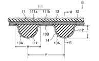
- the toothed belt B is a meshing transmission belt in which a plurality of tooth portions 10A are arranged at predetermined pitches on the inner peripheral side.
- the tooth portion 10 ⁇ / b> A is a so-called round tooth having a semicircular ridge formed in a side view shape so as to extend in the belt width direction.
- the tooth height H of the tooth part 10A is defined by the dimension from the tooth bottom part 10B to the tip of the tooth part 10A between a pair of tooth parts 10A adjacent to each other in the belt length direction, for example, 2.5 mm or more and 4.0 mm. It is as follows.
- the tooth width W of the tooth portion 10A is defined by the dimension between the ends of a pair of tooth bottom portions 10B adjacent to each other across the tooth portion 10A in the belt length direction, and is, for example, 4.5 mm or more and 8.0 mm or less.
- the tooth pitch P of the tooth portion 10A is, for example, not less than 6.0 mm and not more than 10.0 mm.
- the tooth portion 10A may have other shapes such as a trapezoidal tooth, or may be a helical tooth formed so as to extend in a direction inclined with respect to the belt width direction.
- the toothed belt B according to Embodiment 1 includes a belt body 11, a core wire 12, a back reinforcing cloth 13, and a tooth portion reinforcing cloth 14.
- the belt main body 11 is made of rubber and has a back rubber part 111 and a plurality of tooth rubber parts 112.
- the back rubber part 111 is formed in an endless flat belt shape.
- the thickness of the back rubber part 111 is, for example, not less than 1.5 mm and not more than 4.0 mm.
- the plurality of tooth rubber portions 112 are arranged on the inner peripheral side of the back rubber portion 111 at a predetermined pitch corresponding to the tooth portion 10A, and each is formed in a shape corresponding to the tooth portion 10A. And provided integrally with the back rubber part 111.
- the height h of the tooth rubber part 112 is defined by the dimension from the innermost peripheral part of the core wire 12 embedded in the back rubber part 111 to the tip of the tooth rubber part 112, for example, 2.5 mm or more and 4.0 mm or less. is there.
- the core wire 12 is embedded in a surface layer on the inner peripheral side of the back rubber part 111 of the belt body 11 so as to form a spiral having a pitch in the belt width direction and extending in the circumferential direction.
- the core wire 12 is composed of a twisted yarn formed of glass fiber, aramid fiber, carbon fiber, metal fiber or the like.
- the core 12 is preferably provided so that the S twisted yarn and the Z twisted yarn form a double helix, but may be composed of a single S twisted yarn or a Z twisted yarn.
- the diameter of the core wire 12 is, for example, not less than 0.5 mm and not more than 2.5 mm.
- the gap between the core wires 12 adjacent to each other in the belt width direction is substantially constant, and is, for example, not less than 0.5 mm and not more than 3.0 mm.
- the back reinforcing cloth 13 is pasted so as to cover the outer peripheral surface of the back rubber part 111 of the belt main body 11.
- the tooth portion reinforcing cloth 14 is pasted so as to cover the inner peripheral surface of the belt body 11 on which the plurality of tooth rubber portions 112 are provided. Accordingly, the tooth rubber portion 112 is covered with the tooth portion reinforcing cloth 14 to constitute each tooth portion 10A.
- the core wire 12 embedded in the back rubber portion 111 of the belt main body 11 is disposed immediately inside the tooth portion reinforcing cloth 14.
- the back reinforcing cloth 13 and the tooth reinforcing cloth 14 are made of, for example, a woven fabric, a knitted fabric, a non-woven fabric, or the like formed of yarns such as nylon fibers (polyamide fibers), polyester fibers, aramid fibers, and cotton.
- the back reinforcing cloth 13 and the tooth part reinforcing cloth 14 are preferably made of nylon fiber woven cloth.
- the back reinforcing cloth 13 and the tooth part reinforcing cloth 14 preferably have elasticity, such as a woven cloth in which weft processing is applied to the weft.
- the back reinforcing cloth 13 and the tooth reinforcing cloth 14 are bonded to the belt main body 11 by being soaked in a so-called RFL aqueous solution and then heated, soaked in a low-viscosity rubber paste and dried, and high It is preferable that one or two or more types of adhesion treatment is applied among coating treatments in which a rubber paste having a viscosity is applied to the surface of the belt body 11 and dried.
- the back reinforcing cloth 13 and the tooth part reinforcing cloth 14 may be subjected to a base treatment that is heated after being immersed in an epoxy solution or an isocyanate solution before the adhesion treatment.
- the thickness of the back reinforcing cloth 13 and the tooth reinforcing cloth 14 is, for example, not less than 0.3 mm and not more than 2 mm.
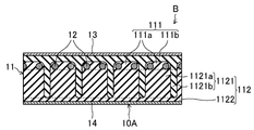
- the belt body 11 is formed of a first rubber composition having a relatively high rubber hardness and a second rubber composition having a relatively low rubber hardness.
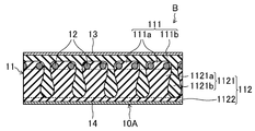
- the back rubber portion 111 of the belt main body 11 includes a plurality of core wire-covered rubber portions 111a and other back rubber portions 111b.
- the plurality of core wire-covered rubber portions 111a are arranged at intervals in the belt width direction.
- Each of the plurality of core wire-covered rubber portions 111 a is provided so that one core wire 12 is embedded and covers the core wire 12.
- the core wire-covered rubber portion 111a is formed of a high hardness first rubber composition.
- the back rubber part 111b constitutes a back layer of the back rubber part 111, and a back reinforcing cloth 13 is provided.
- the back rubber portion 111b is formed of a low hardness second rubber composition.
- Each of the plurality of tooth rubber portions 112 of the belt main body 11 includes an inner rubber portion 1121 and a surface rubber portion 1122 provided so as to cover the inner peripheral surface thereof.
- the internal rubber portion 1121 is configured by alternately laminating high hardness rubber layers 1121a and low hardness rubber layers 1121b in the belt width direction.
- the high-hardness rubber layer 1121a is provided corresponding to each of the plurality of core wire-covered rubber portions 111a of the back rubber portion 111 in the belt width direction.
- the high-hardness rubber layer 1121a is formed of the same high-hardness first rubber composition as the core wire-covered rubber portion 111a of the back rubber portion 111. Therefore, the high-hardness rubber layer 1121a is configured continuously with the corresponding core wire-covered rubber portion 111a.
- the low hardness rubber layer 1121b is provided corresponding to the gap between the adjacent core wires 12 in the belt width direction.
- the low-hardness rubber layer 1121b is formed of the same low-hardness second rubber composition as the back rubber part 111b of the back rubber part 111, and is thus configured continuously with the back rubber part 111b. All the low-hardness rubber layers 1121b are connected via the back rubber portion 111b.
- Each of the high-hardness rubber layer 1121a and the low-hardness rubber layer 1121b may have a substantially constant layer thickness in the belt cross-section along the belt thickness direction.
- the layer thickness of the high hardness rubber layer 1121a is, for example, not less than 0.5 mm and not more than 3.0 mm.
- the layer thickness of the low hardness rubber layer 1121b is, for example, not less than 0.5 mm and not more than 3.0 mm.
- the low-hardness rubber layer 1121b is formed so as to hang down from the gap between the core wires 12 adjacent to each other in the belt width direction.
- the shape of the low hardness rubber layer 1121b in the longitudinal section of the belt is preferably a semicircular shape corresponding to the shape of the tooth rubber portion 112.
- the average dimension l from the innermost peripheral portion of the core wire 12 embedded in the back rubber portion 111 to the tip of the low hardness rubber layer 1121b is determined from the viewpoint of obtaining excellent high load durability and impact resistance described later.
- the height h of the rubber part 112 is preferably 30% or more, more preferably 50% or more, and even more preferably 70% or more.
- the surface rubber portion 1122 is formed of the same high hardness first rubber composition as the core wire covering rubber portion 111a and the high hardness rubber layer 1121a. Therefore, the surface rubber portion 1122 is continuous with the high hardness rubber layer 1121a of the inner rubber portion 1121. Configured. All the core wire covering rubber portions 111a and the high hardness rubber layer 1121a are connected via the surface rubber portion 1122.
- the thickness of the surface rubber portion 1122 is, for example, not less than 0.5 mm and not more than 4.0 mm.
- the first and second rubber compositions are obtained by heating and pressurizing the first and second uncrosslinked rubber compositions in which various rubber compounding agents are blended in the rubber component, and the rubber component is crosslinked by the crosslinking agent. is there.
- the rubber component of the first and second rubber compositions examples include hydrogenated acrylonitrile rubber (hereinafter referred to as “H-NBR”) and H-NBR reinforced by finely dispersing an unsaturated metal salt such as zinc methacrylate. (Hereinafter referred to as “reinforced H-NBR”), ethylene- ⁇ -olefin elastomers such as chlorosulfonated polyethylene rubber, chloroprene rubber, ethylene propylene diene terpolymer (EPDM), and the like. It is preferable to use one or more of these rubber components.
- the first and second rubber compositions preferably include the same rubber component.
- the rubber component of the first and second rubber compositions preferably contains at least one of H-NBR and reinforced H-NBR. More preferably, the rubber component of the high hardness first rubber composition is a blend rubber of H-NBR and reinforced H-NBR, and the rubber component of the low hardness second rubber composition is only H-NBR.
- rubber compounding agents examples include processing aids, vulcanization acceleration aids, anti-aging agents, reinforcing materials, plasticizers, co-crosslinking agents, short fibers, and crosslinking agents.
- processing aids include stearic acid, polyethylene wax, and fatty acid metal salts. It is preferable to use one or more of these processing aids.
- the content of the processing aid is, for example, 0.3 parts by mass or more and 0.7 parts by mass or less with respect to 100 parts by mass of the rubber component.
- the vulcanization acceleration aid examples include metal oxides such as zinc oxide (zinc white) and magnesium oxide, metal carbonates, fatty acids and derivatives thereof. It is preferable to use one kind or two or more kinds of vulcanization acceleration aids.
- the content of the vulcanization acceleration aid is, for example, 3 parts by mass or more and 15 parts by mass or less with respect to 100 parts by mass of the rubber component.
- the antiaging agent examples include benzimidazole type, aromatic secondary amine type, amine-ketone type and the like. It is preferable to use one or more of these antiaging agents.
- the content of the antioxidant is, for example, 1.5 parts by mass or more and 3.5 parts by mass or less with respect to 100 parts by mass of the rubber component.
- Reinforcing materials include carbon black, calcium carbonate, silica and the like. It is preferable to use one or more of these reinforcing materials.
- Examples of carbon black include channel black; furnace black such as SAF, ISAF, N-339, HAF, N-351, MAF, FEF, SRF, GPF, ECF, and N-234; thermal black such as FT and MT; Examples include acetylene black. It is preferable to use one or more of these carbon blacks.
- the content of carbon black is, for example, from 0.1 parts by weight to 50 parts by weight with respect to 100 parts by weight of the rubber component.
- the content thereof is, for example, 5 parts by mass or more and 15 parts by mass or less with respect to 100 parts by mass of the rubber component.
- silica is used as the reinforcing material, the content thereof is, for example, 10 parts by mass or more and 30 parts by mass or less with respect to 100 parts by mass of the rubber component.
- plasticizer examples include polyether esters, dialkyl sebacates such as dioctyl sebacate (DOS), dialkyl phthalates such as dibutyl phthalate (DBP) and dioctyl phthalate (DOP), and dialkyl adipates such as dioctyl adipate (DOA). Can be mentioned. It is preferable to use one or more of these plasticizers. Content of a plasticizer is 3 to 15 mass parts with respect to 100 mass parts of rubber components, for example.
- DOS dioctyl sebacate
- DBP dibutyl phthalate
- DOP dioctyl phthalate
- DOA dioctyl adipate
- co-crosslinking agent examples include trimethylolpropane trimethacrylate, m-phenylene dimaleimide, zinc dimethacrylate, triallyl isocyanurate and the like. It is preferable to use one or more of these co-crosslinking agents.
- the content of the co-crosslinking agent is, for example, 1 part by mass or more and 8 parts by mass or less with respect to 100 parts by mass of the rubber component.
- Examples of the short fibers include aramid short fibers, nylon short fibers, polyester short fibers, and the like.
- the length of the short fiber is, for example, 1 mm or more and 3 mm or less. It is preferable to use one or more of these short fibers.
- the content of the short fiber is, for example, 1 part by mass or more and 5 parts by mass or less with respect to 100 parts by mass of the rubber component.
- the crosslinking agent examples include sulfur and organic peroxides.
- a crosslinking agent only sulfur may be used, only an organic peroxide may be used, and furthermore, both of them may be used in combination.
- the combined use of sulfur and organic peroxide is preferable.
- the amount of the crosslinking agent is, for example, 0.1 to 0.7 parts by mass of sulfur with respect to 100 parts by mass of the rubber component.
- the organic peroxide is 2 parts by mass or more and 5 parts by mass or less.
- the rubber hardness of the first rubber composition is higher than that of the second rubber composition.
- Rubber hardness of the first rubber composition from the viewpoint of obtaining excellent high load durability and impact resistance will be described later, preferably not more than 85H A more 95H A, more preferably not more than 88H A more 94H A.
- Rubber hardness of the second rubber composition from the same viewpoint, preferably less 50H A more 80H A, more preferably not more than 65H A more 75H A. From the same viewpoint, the difference in rubber hardness between the first and second rubber compositions is preferably 5 HA or more and 45 HA or less, more preferably 13 HA or more and 29 HA or less.
- the ratio of the rubber hardness of the first rubber composition to the rubber hardness of the second rubber composition is preferably 1.1 or more and 1.9 or less, more preferably 1.2 or more and 1.5 or less. More preferably, it is 1.2 or more and 1.4 or less.
- Tensile strength T B at 25 ° C. of Retsuri direction of the first rubber composition from the viewpoint of obtaining excellent high load durability and impact resistance will be described later, preferably 20MPa or more 40MPa or less, and more preferably at least 25MPa 35 MPa or less.
- Tensile strength T B at 25 ° C. of Retsuri direction of the second rubber composition from the same viewpoint, preferably 15MPa or more 35MPa or less, more preferably 30MPa or more 20 MPa.
- Tensile strength T B of the first rubber composition is preferably high than the tensile strength T B of the second rubber composition.
- Elongation E B at Retsuri direction 25 ° C. of the first rubber composition from the viewpoint of obtaining excellent high load durability and impact resistance below, preferably 300% to 100% or less, more preferably 150% More than 250%.
- Elongation E B at Retsuri direction 25 ° C. of the second rubber composition from the same viewpoint, it is preferably 550% or more 350% or less, more preferably 500% or less than 400%.
- Elongation E B of the first rubber composition is preferably less than the elongation E B of the second rubber composition.
- the tensile stress M 100 at 100% at 25 ° C. in the direction of the first rubber composition is preferably from 10 MPa to 30 MPa, more preferably from the viewpoint of obtaining excellent high load durability and impact resistance described later. 15 MPa or more and 25 MPa or less. From the same viewpoint, the tensile stress M 100 at 100% at 25 ° C. in the direction of the second rubber composition is preferably 1.5 MPa to 5.5 MPa, more preferably 2.5 MPa to 4.5 MPa. It is. 100% tensile stress M 100 of the first rubber composition is preferably higher than the stress M 100 Tensile at 100% of the second rubber composition.
- the rubber hardness of the first and second rubber compositions is measured using a type A durometer based on JIS K6253.
- the tensile strength T B , elongation E B , and 100% tensile stress M 100 in the row direction of the first and second rubber compositions are measured by a tensile test based on JIS K6301.
- the toothed belt B according to the first embodiment having the above configuration is wound between a crankshaft pulley and an OHC pulley and used as a power transmission member for transmitting the former power to the latter.
- the toothed belt B According to the toothed belt B according to the first embodiment, the tooth rubber portion 112 is relatively relative to the high hardness rubber layer 1121a formed of the first rubber composition having relatively high rubber hardness.
- a low-hardness rubber layer 1121b formed of a second rubber composition having a low rubber hardness has internal rubber portions 1121 that are alternately laminated in the belt width direction, and covers the inner peripheral surface thereof.
- the surface rubber portion 1122 provided is formed of the first rubber composition having the same relatively high rubber hardness as the high hardness rubber layer 1121a, thereby obtaining excellent high load durability and impact resistance. Can do. This is because deformation of the tooth rubber portion 112 is suppressed by the high hardness surface rubber portion 1122, so that it is possible to avoid the occurrence of peak distortion that directly connects to the tooth chip in the tooth rubber portion 112.
- the internal rubber portion 1121 has an alternately laminated structure of the high-hardness rubber layer 1121a and the low-hardness rubber layer 1121b, so that the followability to the deformation of the tooth rubber portion 112 is enhanced and the load distribution applied to the tooth rubber portion 112 is increased. This is presumed to be because it is possible to avoid the occurrence of peak stress that is directly connected to the tooth chipping in the tooth rubber portion 112.
- the manufacturing method of the toothed belt B according to Embodiment 1 includes a material preparation process, a molding process, a crosslinking process, and a finishing process.
- a predetermined rubber component is masticated, and various rubber compounding agents are added thereto and kneaded to obtain a first uncrosslinked rubber composition that forms a first rubber composition having a relatively high rubber hardness.
- the sheet-like 1st uncrosslinked rubber composition 151 is produced by carrying out the calendar shaping
- a second uncrosslinked rubber composition that forms a second rubber composition having a relatively low rubber hardness by kneading a predetermined rubber component and adding and kneading various rubber compounding agents therein. Get. Then, the obtained second uncrosslinked rubber composition is calendered to produce a sheet-like second uncrosslinked rubber composition 152.
- FIG. 7 shows the belt mold 20.
- the belt forming die 20 is cylindrical and has an outer peripheral surface in which a plurality of tooth portion forming grooves 21 formed so as to extend in the axial direction are arranged at intervals in the circumferential direction.
- a cylindrical tooth portion reinforcing cloth 14 is placed on the outer peripheral surface of the belt forming die 20, and the core wire 12 is wound spirally from above.
- the core wire 12 is composed of S-twisted yarn and Z-twisted yarn
- the distance between the centers of the S-twisted yarn and the Z-twisted yarn is made constant, and the distance between the centers.
- These S-twisted yarns and Z-twisted yarns may be wound in a double helix shape at a pitch twice as large as the above.
- what is necessary is just to wind the core wire 12 in a helical form with a fixed pitch, when comprising with the single S twist yarn or Z twist yarn.
- a sheet-like first uncrosslinked rubber composition 151 and a sheet-like second uncrosslinked rubber composition 152 are wound around the sheet in order.
- the first uncrosslinked rubber composition 151 is preferably wound thicker than the second uncrosslinked rubber composition 152 from the viewpoint of obtaining excellent high load durability and impact resistance.
- the ratio of the volume of the first uncrosslinked rubber composition 151 to the volume of the second uncrosslinked rubber composition 152 is preferably greater than 1, more preferably 1.5 or more, and preferably 3.5 or less, more preferably 2.5 or less. It is preferable to use the sheet-like first and second uncrosslinked rubber compositions 151 and 152 so that the alignment direction corresponds to the belt length direction.
- FIG. 8B an uncrosslinked slab S ′ on the belt mold 20 is covered with a rubber sleeve 22, which is placed in a vulcanizing can and sealed, and high-temperature and high-pressure steam is put into the vulcanizing can. Fill and hold for a predetermined molding time.
- the first and second uncrosslinked rubber compositions 151 and 152 are passed between the core wires 12 as shown in FIG. While pressing the reinforcing portion, the reinforcing portion is caused to flow into each of the plurality of tooth portion forming grooves 21 of the belt mold 20 and to be bridged.
- the core wire 12, the back reinforcing cloth 13, and the tooth reinforcing cloth 14 are combined and integrated, and finally a cylindrical belt slab S is formed as shown in FIG. 8D.
- the first uncrosslinked rubber composition 151 is 100 ° C. than the second uncrosslinked rubber composition 152.
- the Mooney viscosity at is preferably high.
- the Mooney viscosity at 100 ° C. of the first uncrosslinked rubber composition 151 is preferably 40 ML 1 + 4 (100 ° C.) or more, more preferably 50 ML 1 + 4 (100 ° C.) or more, and preferably 70 ML 1 + 4 (100 ° C.) or less. More preferably, it is 60 ML 1 + 4 (100 ° C.) or less.
- the ratio of the Mooney viscosity at 100 ° C. of the first uncrosslinked rubber composition 151 to the Mooney viscosity at 100 ° C. of the second uncrosslinked rubber composition 152 is preferably greater than 1 and less than or equal to 2.0, more preferably 1. 5 or less. Mooney viscosity is measured based on JIS K6300.
- ⁇ Finishing process> The inside of the vulcanizing can is depressurized to release the seal, the belt slab S molded between the belt mold 20 and the rubber sleeve 22 is taken out, removed from the mold, and cut into a predetermined width to cut the toothed belt B. obtain.
- Embodiment 2 9 and 10 show a toothed belt B according to the second embodiment.
- the part of the same name as Embodiment 1 is shown with the same code
- FIG. 1 is a diagrammatic representation of Embodiment 1.
- the toothed belt B according to the second embodiment has a relatively small gap and a relatively large gap between the core wires 12 adjacent to each other in the belt width direction. Specifically, relatively small gaps and relatively large gaps between the core wires 12 are alternately arranged in the belt width direction. In the portion where the gap between the core wires 12 is relatively small, the core wire covering rubber portion 111a of the back rubber portion 111 is embedded with a pair of core wires 12 adjacent to each other in the belt width direction across the small gap. And is provided so as to cover the pair of core wires 12.
- the low hardness rubber layer 1121b of the inner rubber portion 1121 of the tooth rubber portion 112 is formed so as to hang down from the large gap to the inner peripheral side in the belt cross section. ing. That is, in the toothed belt B according to the second embodiment, the low-hardness rubber layer 1121b is not provided corresponding to the relatively small gap between the core wires 12, but the high-hardness rubber layer 1121a is provided. The low hardness rubber layer 1121b is provided corresponding to the relatively large gap between the core wires 12.
- the relatively small gap between the core wires 12 is, for example, not less than 0.01 mm and not more than 0.5 mm.
- the relatively large gap between the core wires 12 is, for example, not less than 0.5 mm and not more than 1.5 mm.
- the ratio of the large gap to the relatively small gap between the core wires 12 is preferably 0.6 or more and 100 or less.
- the core wire 12 is composed of S-twisted yarn and Z-twisted yarn, and the center distance between the S-twisted yarn and Z-twisted yarn is constant when the uncrosslinked slab S ′ is formed.
- the S-twisted yarn and the Z-twisted yarn may be wound in a double spiral shape at a pitch larger than twice the center distance. Accordingly, in this case, the pair of core wires 12 covered with the same core wire-covered rubber portion 111a becomes an S twist yarn and a Z twist yarn.
- the high-hardness rubber layer 1121a and the low-hardness rubber layer 1121b have a configuration in which the layer thickness in the belt cross-section is substantially constant along the belt thickness direction.
- the layer thickness in the belt cross section gradually increases from the base end side along the belt thickness direction.
- the cross-sectional shape which becomes suddenly small at the tip after becoming a water droplet shape may be formed.
- Such a configuration can be obtained by adjusting the fluidity of the first and second uncrosslinked rubber compositions 151 and 152 by blending design.
- the low hardness rubber layer 1121b is provided corresponding to the gaps between all the core wires 12.
- the present invention is not limited to this, and as shown in FIG. A portion where the low-hardness rubber layer 1121b is not provided may be included corresponding to the gap between the two.
- the back reinforcing cloth 13 is provided.
- the present invention is not particularly limited thereto, and the back rubber part 111 is exposed without the back reinforcing cloth 13. Also good.
- this rubber component for 100 parts by mass of this rubber component, 5 parts by mass of zinc oxide as a vulcanization accelerator, 2.5 parts by mass of anti-aging agent, 20 parts by mass of carbon black as a reinforcing material, 20 parts by mass of silica, 5 parts by mass of plasticizer, 6 parts by mass of co-crosslinking agent, 3 parts by mass of aramid short fibers (1 mm), 0.3 part by mass of sulfur of the crosslinking agent, and 3.2 mass of organic peroxide of the crosslinking agent
- the first uncrosslinked rubber composition was prepared by charging and mixing the parts.
- H-NBR (Second uncrosslinked rubber composition) H-NBR (trade name: Zetpol 2000, manufactured by Nippon Zeon Co., Ltd.) as a rubber component is introduced into a chamber of a closed Banbury mixer and masticated. Then, with respect to 100 parts by mass of the rubber component, a processing aid of 0.
- a second uncrosslinked rubber composition was prepared by charging and mixing 3 parts by mass of a crosslinking agent, 0.5 parts by mass of sulfur as a crosslinking agent, and 3.2 parts by mass of an organic peroxide as a crosslinking agent.
- Each of the first and second uncrosslinked rubber compositions was molded into a sheet by calendar molding. Using these sheet-like first and second uncrosslinked rubber compositions (67% by volume of the first uncrosslinked rubber composition and 33% by volume of the second uncrosslinked rubber composition) and having no back reinforcing fabric Except for the above, a toothed belt having the same configuration as that of the first embodiment was produced and used as an example.
- the belt length is 1381 mm
- the belt width is 25 mm
- the belt thickness is 6.3 mm.
- the tooth height H is 3.5 mm
- the tooth width W is 7.4 mm
- the tooth pitch P is 9.525 mm.
- the height h of the tooth rubber part was 3.0 mm.
- the average thickness of the high hardness rubber layer was 1.5 mm
- the average thickness of the low hardness rubber layer was 1.5 mm.
- the average thickness of the surface rubber portion was 1.0 mm.
- the dimension l from the innermost peripheral portion of the core wire to the tip of the low hardness rubber layer was 67% on average with respect to the height h of the tooth rubber portion.
- a glass fiber twisted yarn subjected to adhesion treatment was used for the core wire and a nylon 6,6 fiber woven fabric subjected to adhesion treatment was used for the tooth reinforcement fabric.
- Comparative Examples 1 and 2 A toothed belt was produced in the same manner as in Example except that the belt body was formed using only the sheet-like first uncrosslinked rubber composition, and this was designated as Comparative Example 1. Further, a toothed belt was produced in the same manner as in Example except that the belt body was formed using only the sheet-like second uncrosslinked rubber composition, and this was designated as Comparative Example 2.
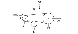
- FIG. 13 shows a pulley layout of a belt running test machine 30 for a high load endurance test.
- the belt running test machine 30 has a drive pulley 31, a driven pulley 32 provided on the right side thereof, and an idler pulley 33 provided on the lower side therebetween.
- a drive pulley 31 On the outer periphery of the drive pulley 31, 21 tooth meshing grooves are provided.
- On the outer periphery of the driven pulley 32 42 tooth-engagement grooves are provided.
- the outer diameter of the idler pulley 33 is 52 mm.
- each toothed belt B of Example and Comparative Examples 1 and 2 it is wound around the drive pulley 31, the driven pulley 32, and the idler pulley 33 of the belt running test machine 30, and the driven pulley 32 is dead to the right by 1200N.
- a belt running test was performed by loading the weight DW and rotating the driving pulley at a rotational speed of 6000 rpm under an atmospheric temperature of 100 ° C. Then, the number of rotations until the toothed belt was damaged was measured.
- FIG. 14 shows a pulley layout of a belt testing machine 40 for an impact resistant vibration test.
- This belt testing machine 40 includes a driving pulley 41, a fixed first driven pulley 42 provided obliquely below the left side, a second driven pulley 43 provided obliquely above the left side, a driving pulley 41, a first pulley Three idler pulleys 44 disposed between the driven pulley 42 and the second driven pulley 43, and the tension provided immediately above the idler pulley 44 between the first driven pulley 42 and the second driven pulley 43. And an imparting pulley 45.
- On the outer periphery of the drive pulley 41 22 tooth-engagement grooves are provided.
- On the outer periphery of the first driven pulley 42 22 tooth-engagement grooves are provided.
- 44 tooth-engagement grooves are provided on the outer periphery of the second driven pulley 43.
- the outer diameter of the idler pulley 44 is 28.5 mm.
- the outer diameter of the tension applying pulley 45 is 67.7 mm.
- the belt tester 40 meshes with the drive pulley 41, the first driven pulley 42, and the second driven pulley 43, and the idler pulley. 44 and the tension applying pulley 45 are wound so that the back surface of the belt comes into contact with each other, and a set weight is loaded by the tension applying pulley 45 so that the belt tension becomes 800 N, and the drive pulley 41 is moved in the forward direction at an ambient temperature of 25 ° C.
- a rotation vibration test is performed in which the rotation direction is changed to the reverse direction when a predetermined load is generated on the drive pulley 41, and the rotation direction is changed to the forward direction again when a predetermined load is generated on the drive pulley 41. went. And the frequency
- Test results The test results are shown in Tables 3 and 4.
- the first rubber composition obtained by crosslinking the first uncrosslinked rubber composition has higher hardness than the second rubber composition obtained by crosslinking the second uncrosslinked rubber composition. It was confirmed that.
- the first uncrosslinked rubber composition forming the first hard rubber composition has a Mooney viscosity at 100 ° C. lower than the second uncrosslinked rubber composition forming the second hard rubber composition. I understand.
- the first rubber composition to crosslink the first uncrosslinked rubber composition than the second rubber composition obtained by crosslinking the second uncrosslinked rubber composition, high strength T B tensile Retsuri direction , small elongation E B, and it can be seen high 100% tensile stress M 100.
- the tooth rubber part is a low hardness rubber formed of a high hardness rubber layer formed of a high hardness first rubber composition and a low hardness second rubber composition.
- An embodiment having an inner rubber portion in which layers are alternately laminated in the belt width direction and a surface rubber portion formed of a high hardness first rubber composition provided so as to cover the inner rubber portion Compared with Comparative Example 1 in which only the first rubber composition with high hardness is formed and Comparative Example 2 in which the tooth rubber part is formed with only the second rubber composition with low hardness, high load durability and impact resistance It turns out that both are excellent.
- the present invention is useful in the technical field of a toothed belt and a manufacturing method thereof.
- Toothed belt S Belt slab S 'Uncrosslinked slab 10A Tooth part 10B Tooth base 11 Belt body 111 Back rubber part 111a Core wire covering rubber part 111b Back rubber part 112 Tooth rubber part 1121 Internal rubber part 1121a High hardness rubber layer 1121b Low Hardness rubber layer 1122 Surface rubber part 12 Core wire 13 Back reinforcing cloth 14 Tooth part reinforcing cloth 151 First uncrosslinked rubber composition 152 Second uncrosslinked rubber composition 20 Belt mold 21 Tooth part forming groove 22 Rubber sleeves 30, 40 Belt running tester 31, 41 Drive pulley 32 Driven pulley 33, 44 Idler pulley 42 First driven pulley 43 Second driven pulley 45 Tensioning pulley
Abstract
歯付ベルト(B)は、歯ゴム部(12)が、相対的にゴム硬さの高い第1ゴム組成物で形成された高硬度ゴム層(1121a)と相対的にゴム硬さの低い第2ゴム組成物で形成された低硬度ゴム層(1121b)とがベルト幅方向に交互に積層された内部ゴム部分(1121)と、内部ゴム部分(1121)の内周側表面を被覆するように設けられ高硬度ゴム層(1121a)と同一の相対的にゴム硬さの高い第1ゴム組成物で形成された表面ゴム部分(1122)とを含む。
Description
本発明は、歯付ベルト及びその製造方法に関する。
自動車エンジンにおいて、クランクシャフトの動力を利用してオーバーヘッドカムシャフトを回転駆動するための動力伝達部材として歯付ベルトが用いられている。かかる歯付ベルトは、一般に、エンドレスの平帯状の背ゴム部の内周側に所定ピッチで間隔をおいて複数の歯ゴム部が一体に設けられたゴム製のベルト本体を備えており、通常、ベルト本体の歯ゴム部が設けられた内周側の表面が歯部補強布で被覆された構成を有する。特許文献1には、背ゴム部のゴム硬さが歯ゴム部よりも高く且つ背ゴム部の外周面から歯ゴム部の内周面に向かってゴム硬さが連続的に低下している歯付ベルトが開示されている。特許文献2には、歯ゴム部を短繊維を含むゴム組成物で形成して高硬度化する一方、ベルト本体の歯ゴム部が設けられた内周側の表面を被覆する歯部補強布の外側を低硬度ゴム層で更に被覆して耐摩耗性及び衝撃吸収性を高めた歯付ベルトが開示されている。
本発明は、エンドレスの平帯状の背ゴム部と、前記背ゴム部の内周側に所定ピッチで間隔をおいて配設されて各々が前記背ゴム部に一体に設けられた複数の歯ゴム部とを有するゴム製のベルト本体を備えた歯付ベルトであって、前記複数の歯ゴム部のそれぞれは、相対的にゴム硬さの高い第1ゴム組成物で形成された高硬度ゴム層と相対的にゴム硬さの低い第2ゴム組成物で形成された低硬度ゴム層とがベルト幅方向に交互に積層された内部ゴム部分と、前記内部ゴム部分の内周側表面を被覆するように設けられ前記高硬度ゴム層と同一の相対的にゴム硬さの高い第1ゴム組成物で形成された表面ゴム部分とを含む。
本発明は、本発明の歯付ベルトの製造方法であって、各々、軸方向に延びるように形成された複数の歯部形成溝が周方向に間隔をおいて配設された外周面を有するベルト成形型を用い、前記ベルト成形型の外周面に心線を螺旋状に巻き付けた後、その上に前記相対的にゴム硬さの高い第1ゴム組成物を形成するシート状の第1未架橋ゴム組成物及び前記相対的にゴム硬さの低い第2ゴム組成物を形成するシート状の第2未架橋ゴム組成物を順に巻き付けて前記ベルト成形型上に未架橋スラブを成形し、前記未架橋スラブを前記ベルト成形型側に押圧すると共に加熱することにより、前記第1及び第2未架橋ゴム組成物を前記心線間に通して前記ベルト成形型の前記複数の歯部形成溝のそれぞれに流入させると共に架橋させるものである。
以下、実施形態について詳細に説明する。
(実施形態1)
図1~6は、実施形態1に係る歯付ベルトBを示す。実施形態1に係る歯付ベルトBは、例えば自動車エンジンにおいて、クランクシャフトの動力を利用してオーバーヘッドカムシャフト(OHC)を回転駆動するための動力伝達部材として用いられるものである。実施形態1に係る歯付ベルトBは、例えば、ベルト長さが700mm以上2300mm以下、ベルト幅が10mm以上40mm以下、及びベルト厚さが4.5mm以上7.0mm以下である。
図1~6は、実施形態1に係る歯付ベルトBを示す。実施形態1に係る歯付ベルトBは、例えば自動車エンジンにおいて、クランクシャフトの動力を利用してオーバーヘッドカムシャフト(OHC)を回転駆動するための動力伝達部材として用いられるものである。実施形態1に係る歯付ベルトBは、例えば、ベルト長さが700mm以上2300mm以下、ベルト幅が10mm以上40mm以下、及びベルト厚さが4.5mm以上7.0mm以下である。
実施形態1に係る歯付ベルトBは、内周側に所定ピッチで間隔をおいて複数の歯部10Aが配設された噛み合い伝動ベルトである。歯部10Aは、ベルト幅方向に延びるように形成された側面視形状が半円形の突条で構成されたいわゆる丸歯である。歯部10Aの歯高さHは、ベルト長さ方向に相互に隣接する一対の歯部10A間の歯底部10Bから歯部10Aの先端までの寸法で規定され、例えば2.5mm以上4.0mm以下である。歯部10Aの歯幅Wは、ベルト長さ方向の歯部10Aを挟んだ相互に隣接する一対の歯底部10Bの端間の寸法で規定され、例えば4.5mm以上8.0mm以下である。歯部10Aの歯ピッチPは例えば6.0mm以上10.0mm以下である。なお、歯部10Aは、台形歯等のその他の形状であってもよく、また、ベルト幅方向に対して傾斜する方向に延びるように形成されたハス歯であってもよい。
実施形態1に係る歯付ベルトBは、ベルト本体11、心線12、背面補強布13、及び歯部補強布14を備えている。
ベルト本体11は、ゴム製であって、背ゴム部111と複数の歯ゴム部112とを有する。背ゴム部111は、エンドレスの平帯状に形成されている。背ゴム部111の厚さは例えば1.5mm以上4.0mm以下である。複数の歯ゴム部112は、歯部10Aに対応して背ゴム部111の内周側に所定ピッチで間隔をおいて配設されており、且つ各々が歯部10Aに対応した形状に形成されていると共に背ゴム部111に一体に設けられている。歯ゴム部112の高さhは、背ゴム部111に埋設された心線12の最内周部から歯ゴム部112の先端までの寸法で規定され、例えば2.5mm以上4.0mm以下である。
心線12は、ベルト本体11の背ゴム部111の内周側の表層に、周方向に延びると共にベルト幅方向にピッチを有する螺旋を形成するように埋設されている。心線12は、ガラス繊維、アラミド繊維、カーボン繊維、金属繊維等で形成された撚り糸で構成されている。心線12は、S撚り糸及びZ撚り糸が二重螺旋を形成するように設けられていることが好ましいが、単一のS撚り糸又はZ撚り糸で構成されていてもよい。心線12の直径は例えば0.5mm以上2.5mm以下である。ベルト幅方向に相互に隣接する心線12間の間隙は、ほぼ一定であって、例えば0.5mm以上3.0mm以下である。
背面補強布13は、ベルト本体11の背ゴム部111の外周側の表面を被覆するように貼設されている。歯部補強布14は、ベルト本体11の複数の歯ゴム部112が設けられた内周側の表面を被覆するように貼設されている。従って、歯ゴム部112が歯部補強布14で被覆されて各歯部10Aが構成されている。歯底部10Bでは、ベルト本体11の背ゴム部111に埋設された心線12が歯部補強布14のすぐ内側に配置されている。
背面補強布13及び歯部補強布14は、例えば、ナイロン繊維(ポリアミド繊維)、ポリエステル繊維、アラミド繊維、綿等の糸で形成された織布、編物、不織布等で構成されている。背面補強布13及び歯部補強布14は、これらのうちのナイロン繊維の織布で構成されていることが好ましい。背面補強布13及び歯部補強布14は、例えば、緯糸にウーリー加工等が施された織布のように伸縮性を有することが好ましい。背面補強布13及び歯部補強布14には、ベルト本体11との接着のため、いわゆるRFL水溶液に浸漬した後に加熱するRFL処理、低粘度のゴム糊に浸漬した後に乾燥させるソーキング処理、及び高粘度のゴム糊をベルト本体11側の表面に塗布して乾燥させるコーティング処理のうちの1種又は2種以上の接着処理が施されていることが好ましい。背面補強布13及び歯部補強布14には、接着処理の前に、エポキシ溶液又はイソシアネート溶液に浸漬した後に加熱する下地処理が施されていてもよい。背面補強布13及び歯部補強布14の厚さは例えば0.3mm以上2mm以下である。
実施形態1に係る歯付ベルトBでは、ベルト本体11が相対的にゴム硬さの高い第1ゴム組成物と、相対的にゴム硬さの低い第2ゴム組成物とで形成されている。
ベルト本体11の背ゴム部111は、複数の心線被覆ゴム部分111aと、それ以外の背面ゴム部分111bとを含む。複数の心線被覆ゴム部分111aは、ベルト幅方向に間隔をおいて配設されている。複数の心線被覆ゴム部分111aのそれぞれは、1本の心線12が埋設され且つその心線12を被覆するように設けられている。心線被覆ゴム部分111aは、高硬度の第1ゴム組成物で形成されている。背面ゴム部分111bは、背ゴム部111の背面層を構成し、背面補強布13が帖設されている。背面ゴム部分111bは、低硬度の第2ゴム組成物で形成されている。
ベルト本体11の複数の歯ゴム部112のそれぞれは、内部ゴム部分1121と、その内周側表面を被覆するように設けられた表面ゴム部分1122とを含む。
内部ゴム部分1121は、高硬度ゴム層1121aと低硬度ゴム層1121bとがベルト幅方向に交互に積層されて構成されている。高硬度ゴム層1121aは、ベルト幅方向において、背ゴム部111の複数の心線被覆ゴム部分111aのそれぞれに対応して設けられている。高硬度ゴム層1121aは、背ゴム部111の心線被覆ゴム部分111aと同一の高硬度の第1ゴム組成物で形成されており、従って、対応する心線被覆ゴム部分111aと連続して構成されている。低硬度ゴム層1121bは、ベルト幅方向において、相互に隣接する心線12の間隙に対応して設けられている。低硬度ゴム層1121bは、背ゴム部111の背面ゴム部分111bと同一の低硬度の第2ゴム組成物で形成されており、従って、背面ゴム部分111bと連続して構成されている。また、全ての低硬度ゴム層1121bは背面ゴム部分111bを介して繋がっている。高硬度ゴム層1121a及び低硬度ゴム層1121bのそれぞれは、ベルト横断面における層厚さがベルト厚さ方向に沿ってほぼ一定であってもよい。高硬度ゴム層1121aの層厚さは例えば0.5mm以上3.0mm以下である。低硬度ゴム層1121bの層厚さは例えば0.5mm以上3.0mm以下である。
低硬度ゴム層1121bは、ベルト幅方向に相互に隣接する心線12の間隙から内周側に垂下するように形成されている。ベルト縦断面における低硬度ゴム層1121bの形状は歯ゴム部112の形状に対応した半円形状であることが好ましい。背ゴム部111に埋設された心線12の最内周部からこの低硬度ゴム層1121bの先端までの平均寸法lは、後述の優れた高負荷耐久性及び耐衝撃性を得る観点から、歯ゴム部112の高さhに対して好ましくは30%以上、より好ましくは50%以上、更に好ましくは70%以上である。
表面ゴム部分1122は、心線被覆ゴム部分111a及び高硬度ゴム層1121aと同一の高硬度の第1ゴム組成物で形成されており、従って、内部ゴム部分1121の高硬度ゴム層1121aと連続して構成されている。全ての心線被覆ゴム部分111a及び高硬度ゴム層1121aは表面ゴム部分1122を介して繋がっている。表面ゴム部分1122の厚さは例えば0.5mm以上4.0mm以下である。
第1及び第2ゴム組成物は、それぞれゴム成分に各種のゴム配合剤が配合された第1及び第2未架橋ゴム組成物が加熱及び加圧されてゴム成分が架橋剤により架橋したものである。
第1及び第2ゴム組成物のゴム成分としては、例えば、水素添加アクリロニトリルゴム(以下「H-NBR」という。)、メタクリル酸亜鉛等の不飽和金属塩を微分散させて補強したH-NBR(以下「補強H-NBR」という。)、クロロスルホン化ポリエチレンゴム、クロロプレンゴム、エチレンプロピレンジエンターポリマー(EPDM)などのエチレン-α-オレフィンエラストマー等が挙げられる。ゴム成分は、これらのうちの1種又は2種以上を用いることが好ましい。第1及び第2ゴム組成物は同一のゴム成分を含むことが好ましい。第1及び第2ゴム組成物のゴム成分はH-NBR及び補強H-NBRのうちの少なくとも一方を含むことが好ましい。高硬度の第1ゴム組成物のゴム成分がH-NBR及び補強H-NBRのブレンドゴムであり、且つ低硬度の第2ゴム組成物のゴム成分がH-NBRのみであることがより好ましい。
ゴム配合剤としては、加工助剤、加硫促進助剤、老化防止剤、補強材、可塑剤、共架橋剤、短繊維、架橋剤等が挙げられる。
加工助剤としては、例えば、ステアリン酸、ポリエチレンワックス、脂肪酸の金属塩等が挙げられる。加工助剤は、これらのうちの1種又は2種以上を用いることが好ましい。加工助剤の含有量は、ゴム成分100質量部に対して例えば0.3質量部以上0.7質量部以下である。
加硫促進助剤としては、例えば、酸化亜鉛(亜鉛華)や酸化マグネシウムなどの金属酸化物、金属炭酸塩、脂肪酸及びその誘導体等が挙げられる。加硫促進助剤は、これらのうちの1種又は2種以上を用いることが好ましい。加硫促進助剤の含有量は、ゴム成分100質量部に対して例えば3質量部以上15質量部以下である。
老化防止剤としては、例えば、ベンズイミダゾール系、芳香族第二級アミン系、アミン-ケトン系のもの等が挙げられる。老化防止剤は、これらのうちの1種又は2種以上を用いることが好ましい。老化防止剤の含有量は、ゴム成分100質量部に対して例えば1.5質量部以上3.5質量部以下である。
補強材としては、カーボンブラック、炭酸カルシウム、シリカ等が挙げられる。補強材は、これらのうちの1種又は2種以上を用いることが好ましい。カーボンブラックとしては、例えば、チャネルブラック;SAF、ISAF、N-339、HAF、N-351、MAF、FEF、SRF、GPF、ECF、N-234などのファーネスブラック;FT、MTなどのサーマルブラック;アセチレンブラック等が挙げられる。カーボンブラックは、これらのうちの1種又は2種以上を用いることが好ましい。カーボンブラックの含有量は、ゴム成分100質量部に対して例えば0.1質量部以上50質量部以下である。補強材として炭酸カルシウムを用いる場合、その含有量は、ゴム成分100質量部に対して例えば5質量部以上15質量部以下である。補強材としてシリカを用いる場合、その含有量は、ゴム成分100質量部に対して例えば10質量部以上30質量部以下である。
可塑剤としては、例えば、ポリエーテルエステル、ジオクチルセバケート(DOS)などのジアルキルセバケート、ジブチルフタレート(DBP)、ジオクチルフタレート(DOP)などのジアルキルフタレート、ジオクチルアジペート(DOA)などのジアルキルアジペート等が挙げられる。可塑剤は、これらのうちの1種又は2種以上を用いることが好ましい。可塑剤の含有量は、ゴム成分100質量部に対して例えば3質量部以上15質量部以下である。
共架橋剤としては、例えば、トリメチロールプロパントリメタクリレート、m-フェニレンジマレイミド、亜鉛ジメタクリレート、トリアリルイソシアヌレート等が挙げられる。共架橋剤は、これらのうちの1種又は2種以上を用いることが好ましい。共架橋剤の含有量は、ゴム成分100質量部に対して例えば1質量部以上8質量部以下である。
短繊維としては、例えば、アラミド短繊維、ナイロン短繊維、ポリエステル短繊維等が挙げられる。短繊維の長さは例えば1mm以上3mm以下である。短繊維は、これらのうちの1種又は2種以上を用いることが好ましい。短繊維の含有量は、ゴム成分100質量部に対して例えば1質量部以上5質量部以下である。
架橋剤としては、硫黄及び有機過酸化物が挙げられる。架橋剤として、硫黄のみが用いられてもよく、また、有機過酸化物のみが用いられてもよく、更には、それらの両方が併用されていてもよい。これらのうち硫黄及び有機過酸化物の併用が好ましく、その場合、架橋剤の配合量は、例えば、ゴム成分100質量部に対して、硫黄が0.1質量部以上0.7質量部以下であり、有機過酸化物が2質量部以上5質量部以下である。
第1ゴム組成物のゴム硬さは第2ゴム組成物のゴム硬さはよりも高い。第1ゴム組成物のゴム硬さは、後述の優れた高負荷耐久性及び耐衝撃性を得る観点から、好ましくは85HA以上95HA以下、より好ましくは88HA以上94HA以下である。第2ゴム組成物のゴム硬さは、同様の観点から、好ましくは50HA以上80HA以下、より好ましくは65HA以上75HA以下である。第1及び第2ゴム組成物のゴム硬さの差は、同様の観点から、好ましくは5HA以上45HA以下、より好ましくは13HA以上29HA以下である。第1ゴム組成物のゴム硬さの第2ゴム組成物のゴム硬さに対する比は、同様の観点から、好ましくは1.1以上1.9以下、より好ましくは1.2以上1.5以下、更に好ましくは1.2以上1.4以下である。
第1ゴム組成物の列理方向の25℃での引張強さTBは、後述の優れた高負荷耐久性及び耐衝撃性を得る観点から、好ましくは20MPa以上40MPa以下、より好ましくは25MPa以上35MPa以下である。第2ゴム組成物の列理方向の25℃での引張強さTBは、同様の観点から、好ましくは15MPa以上35MPa以下、より好ましくは20MPa以上30MPa以下である。この第1ゴム組成物の引張強さTBは、第2ゴム組成物の引張強さTBよりも高いことが好ましい。
第1ゴム組成物の列理方向の25℃での伸びEBは、後述の優れた高負荷耐久性及び耐衝撃性を得る観点から、好ましくは100%以上300%以下、より好ましくは150%以上250%以下である。第2ゴム組成物の列理方向の25℃での伸びEBは、同様の観点から、好ましくは350%以上550%以下、より好ましくは400%以上500%以下である。この第1ゴム組成物の伸びEBは、第2ゴム組成物の伸びEBよりも小さいことが好ましい。
第1ゴム組成物の列理方向の25℃での100%時引張応力M100は、後述の優れた高負荷耐久性及び耐衝撃性を得る観点から、好ましくは10MPa以上30MPa以下、より好ましくは15MPa以上25MPa以下である。第2ゴム組成物の列理方向の25℃での100%時引張応力M100は、同様の観点から、好ましくは1.5MPa以上5.5MPa以下、より好ましくは2.5MPa以上4.5MPa以下である。この第1ゴム組成物の100%時引張応力M100は、第2ゴム組成物の100%時引張応力M100よりも高いことが好ましい。
ここで、第1及び第2ゴム組成物のゴム硬さは、JIS K6253に基づいてタイプAデュロメーターを用いて測定されるものである。第1及び第2ゴム組成物の列理方向の引張強さTB、伸びEB、及び100%時引張応力M100は、JIS K6301に基づく引張試験により測定されるものである。
以上の構成の実施形態1に係る歯付ベルトBは、例えば、自動車エンジンにおいて、クランクシャフトプーリ及びOHCプーリ間に巻き掛けられ、前者の動力を後者に伝達するための動力伝達部材として用いられる。
ところで、自動車エンジンにはコンパクト化の要求があり、その要求に対応して歯付ベルトには細幅化が求められる。しかしながら、細幅化した歯付ベルトに対しても、細幅化する前と同等の高負荷耐久性や耐衝撃性が要求される。これに対し、この実施形態1に係る歯付ベルトBによれば、歯ゴム部112が、相対的にゴム硬さの高い第1ゴム組成物で形成された高硬度ゴム層1121aと相対的にゴム硬さの低い第2ゴム組成物で形成された低硬度ゴム層1121bとがベルト幅方向に交互に積層された内部ゴム部分1121を有し、また、その内周側表面を被覆するように設けられた表面ゴム部分1122が高硬度ゴム層1121aと同一の相対的にゴム硬さの高い第1ゴム組成物で形成されていることにより、優れた高負荷耐久性及び耐衝撃性を得ることができる。これは、高硬度の表面ゴム部分1122により歯ゴム部112の変形が抑制されるので、歯ゴム部112に歯欠けに直結するようなピーク歪が生じるのを回避することができ、それに加えて、内部ゴム部分1121が高硬度ゴム層1121aと低硬度ゴム層1121bとの交互積層構造を有することにより、歯ゴム部112の変形に対する追随性が高まると共に、歯ゴム部112に負荷される荷重分布が均一化されるので、歯ゴム部112に歯欠けに直結するようなピーク応力が生じるのを回避することができるためであると推測される。
次に、実施形態1に係る歯付ベルトBの製造方法について図7及び図8A~Dに基づいて説明する。
実施形態1に係る歯付ベルトBの製造方法は、材料準備工程、成形工程、架橋工程、及び仕上げ工程を有する。
<材料準備工程>
所定のゴム成分を素練りし、そこに各種のゴム配合剤を投入して混練することにより相対的にゴム硬さの高い第1ゴム組成物を形成する第1未架橋ゴム組成物を得る。そして、得られた第1未架橋ゴム組成物をカレンダー成形等することによりシート状の第1未架橋ゴム組成物151を作製する。
所定のゴム成分を素練りし、そこに各種のゴム配合剤を投入して混練することにより相対的にゴム硬さの高い第1ゴム組成物を形成する第1未架橋ゴム組成物を得る。そして、得られた第1未架橋ゴム組成物をカレンダー成形等することによりシート状の第1未架橋ゴム組成物151を作製する。
同様に、所定のゴム成分を素練りし、そこに各種のゴム配合剤を投入して混練することにより相対的にゴム硬さの低い第2ゴム組成物を形成する第2未架橋ゴム組成物を得る。そして、得られた第2未架橋ゴム組成物をカレンダー成形等することによりシート状の第2未架橋ゴム組成物152を作製する。
心線12、背面補強布13、及び歯部補強布14のそれぞれに接触処理を施す。また、背面補強布13及び歯部補強布14をそれぞれ筒状に成形する。
<成形工程>
図7はベルト成形型20を示す。
図7はベルト成形型20を示す。
このベルト成形型20は、円筒状であって、各々、軸方向に延びるように形成された複数の歯部形成溝21が周方向に間隔をおいて配設された外周面を有する。
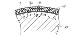
図8Aに示すように、ベルト成形型20の外周面上に筒状の歯部補強布14を被せ、その上から心線12を螺旋状に巻き付ける。ここで、隣接する心線12間の間隙をほぼ一定とするには、心線12をS撚り糸及びZ撚り糸で構成する場合、S撚り糸及びZ撚り糸の中心間距離を一定とし、その中心間距離の2倍の寸法をピッチでそれらのS撚り糸及びZ撚り糸を二重螺旋状に巻き付ければよい。また、心線12を単一のS撚り糸又はZ撚り糸で構成する場合、それを一定ピッチで螺旋状に巻き付ければよい。
次いで、その上にシート状の第1未架橋ゴム組成物151及びシート状の第2未架橋ゴム組成物152を順に巻き付ける。ここで、第1未架橋ゴム組成物151は、優れた高負荷耐久性及び耐衝撃性を得る観点から、第2未架橋ゴム組成物152よりも厚く巻くことが好ましい。第1未架橋ゴム組成物151の体積の第2未架橋ゴム組成物152の体積に対する比は、同様の観点から、好ましくは1より大、より好ましくは1.5以上であり、また、好ましくは3.5以下、より好ましくは2.5以下である。シート状の第1及び第2未架橋ゴム組成物151,152は、列理方向がベルト長さ方向に対応するように使用することが好ましい。
そして、更にその上に筒状の背面補強布13を被せ、ベルト成形型20上に未架橋スラブS’を成形する。
<架橋工程>
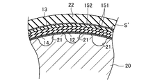
図8Bに示すように、ベルト成形型20上の未架橋スラブS’にゴムスリーブ22を被せ、それを加硫缶内に配置して密閉すると共に、加硫缶内に高温及び高圧の蒸気を充填して所定の成型時間だけ保持する。こうして未架橋スラブS’をベルト成形型側に押圧すると共に加熱することにより、図8Cに示すように、第1及び第2未架橋ゴム組成物151,152を心線12間に通して歯部補強部を押圧させながらベルト成形型20の複数の歯部形成溝21のそれぞれに流入させると共に架橋させる。それと同時に、心線12、背面補強布13、及び歯部補強布14を複合一体化させ、最終的に、図8Dに示すように、円筒状のベルトスラブSを成型する。
図8Bに示すように、ベルト成形型20上の未架橋スラブS’にゴムスリーブ22を被せ、それを加硫缶内に配置して密閉すると共に、加硫缶内に高温及び高圧の蒸気を充填して所定の成型時間だけ保持する。こうして未架橋スラブS’をベルト成形型側に押圧すると共に加熱することにより、図8Cに示すように、第1及び第2未架橋ゴム組成物151,152を心線12間に通して歯部補強部を押圧させながらベルト成形型20の複数の歯部形成溝21のそれぞれに流入させると共に架橋させる。それと同時に、心線12、背面補強布13、及び歯部補強布14を複合一体化させ、最終的に、図8Dに示すように、円筒状のベルトスラブSを成型する。
ここで、図8Cに示すように第1及び第2未架橋ゴム組成物151,152を流動させる観点からは、第1未架橋ゴム組成物151が第2未架橋ゴム組成物152よりも100℃におけるムーニー粘度が高いことが好ましい。第1未架橋ゴム組成物151の100℃におけるムーニー粘度は、好ましくは40ML1+4(100℃)以上、より好ましくは50ML1+4(100℃)以上であり、また、好ましくは70ML1+4(100℃)以下、より好ましくは60ML1+4(100℃)以下である。第2未架橋ゴム組成物152の100℃におけるムーニー粘度は、好ましくは20ML1+4(100℃)以上、より好ましくは30ML1+4(100℃)以上であり、また、好ましくは60ML1+4(100℃)以下、より好ましくは50ML1+4(100℃)以下である。第1未架橋ゴム組成物151の100℃におけるムーニー粘度の第2未架橋ゴム組成物152の100℃におけるムーニー粘度に対する比は、好ましくは1よりも大きく且つ2.0以下、より好ましくは1.5以下である。ムーニー粘度は、JIS K6300に基づいて測定される。
<仕上げ工程>
加硫缶の内部を減圧して密閉を解き、ベルト成形型20とゴムスリーブ22との間に成型されたベルトスラブSを取り出して脱型し、所定幅に輪切りすることにより歯付ベルトBを得る。
加硫缶の内部を減圧して密閉を解き、ベルト成形型20とゴムスリーブ22との間に成型されたベルトスラブSを取り出して脱型し、所定幅に輪切りすることにより歯付ベルトBを得る。
(実施形態2)
図9及び10は、実施形態2に係る歯付ベルトBを示す。なお、実施形態1と同一名称の部分は、実施形態1と同一符号で示す。
図9及び10は、実施形態2に係る歯付ベルトBを示す。なお、実施形態1と同一名称の部分は、実施形態1と同一符号で示す。
実施形態2に係る歯付ベルトBは、ベルト幅方向に相互に隣接する心線12間の間隙が相対的に小さい間隙と相対的に大きい間隙とを有する。具体的には、心線12間の相対的に小さい間隙と相対的に大きい間隙とがベルト幅方向に交互に配設されている。そして、心線12間の間隙が相対的に小さい部分では、背ゴム部111の心線被覆ゴム部分111aが、その小さい間隙を挟んでベルト幅方向に相互に隣接する一対の心線12が埋設され且つそれらの一対の心線12を被覆するように設けられている。心線12間の間隙が相対的に大きい部分では、歯ゴム部112の内部ゴム部分1121の低硬度ゴム層1121bが、ベルト横断面において、その大きい間隙から内周側に垂下するように形成されている。つまり、実施形態2に係る歯付ベルトBでは、心線12間の相対的に小さい間隙に対応しては低硬度ゴム層1121bが設けられておらず、高硬度ゴム層1121aが設けられており、心線12間の相対的に大きい間隙に対応して低硬度ゴム層1121bが設けられている。心線12間の相対的に小さい間隙は、例えば0.01mm以上0.5mm以下である。心線12間の相対的に大きい間隙は、例えば0.5mm以上1.5mm以下である。心線12間の相対的に小さい間隙に対する大きい間隙の比は0.6以上100以下であることが好ましい。
以上の構成の実施形態2に係る歯付ベルトBは、心線12をS撚り糸及びZ撚り糸で構成し、未架橋スラブS’の成形の際に、S撚り糸及びZ撚り糸の中心間距離を一定とし、その中心間距離の2倍の寸法よりも大きいピッチでそれらのS撚り糸及びZ撚り糸を二重螺旋状に巻き付ければよい。従って、この場合、同一の心線被覆ゴム部分111aで被覆される一対の心線12はS撚り糸及びZ撚り糸となる。
その他の構成及び作用効果は実施形態1と同一である。
(その他の実施形態)
上記実施形態1及び2では、高硬度ゴム層1121a及び低硬度ゴム層1121bのそれぞれのベルト横断面における層厚さがベルト厚さ方向に沿ってほぼ一定である構成を示したが、特にこれに限定されるものではなく、実施形態1に対応する図11A及び実施形態2に対応する図11Bに示すように、ベルト横断面における層厚さが基端側からベルト厚さ方向に沿って漸次大きくなった後に先端で急激に小さくなる断面形状が水滴形状に形成されていてもよい。なお、このような構成は、第1及び第2未架橋ゴム組成物151,152の配合設計によりそれらの流動性を調節することにより得ることができる。
上記実施形態1及び2では、高硬度ゴム層1121a及び低硬度ゴム層1121bのそれぞれのベルト横断面における層厚さがベルト厚さ方向に沿ってほぼ一定である構成を示したが、特にこれに限定されるものではなく、実施形態1に対応する図11A及び実施形態2に対応する図11Bに示すように、ベルト横断面における層厚さが基端側からベルト厚さ方向に沿って漸次大きくなった後に先端で急激に小さくなる断面形状が水滴形状に形成されていてもよい。なお、このような構成は、第1及び第2未架橋ゴム組成物151,152の配合設計によりそれらの流動性を調節することにより得ることができる。
実施形態1では、全ての心線12間の間隙に対応して低硬度ゴム層1121bが設けられた構成としたが、特にこれに限定されるものではなく、図12に示すように、心線12間の間隙に対応して低硬度ゴム層1121bが設けられていない部分を含んでいてもよい。
上記実施形態1及び2では、背面補強布13を備えた構成としたが、特にこれに限定されるものではなく、背面補強布13を有さずに背ゴム部111が露出した構成であってもよい。
[未架橋ゴム組成物]
高硬度の第1ゴム組成物及び低硬度の第2ゴム組成物をそれぞれ形成する第1及び第2未架橋ゴム組成物を調製した。それらの配合は表1にも示す。
高硬度の第1ゴム組成物及び低硬度の第2ゴム組成物をそれぞれ形成する第1及び第2未架橋ゴム組成物を調製した。それらの配合は表1にも示す。
(第1未架橋ゴム組成物)
密閉式のバンバリーミキサーのチャンバーにゴム成分としてのH-NBR(日本ゼオン社製 商品名:Zetpol2000)60質量%及び補強H-NBR(日本ゼオン社製 商品名:Zeoforte ZSC2195CX)40質量%を投入して素練りし、次いで、このゴム成分100質量部に対して、加硫促進助剤の酸化亜鉛5質量部、老化防止剤2.5質量部、補強材のカーボンブラック20質量部、補強材のシリカ20質量部、可塑剤5質量部、共架橋剤6質量部、アラミド短繊維(1mm)3質量部、架橋剤の硫黄0.3質量部、及び架橋剤の有機過酸化物3.2質量部を投入配合して混練して第1未架橋ゴム組成物を調製した。
密閉式のバンバリーミキサーのチャンバーにゴム成分としてのH-NBR(日本ゼオン社製 商品名:Zetpol2000)60質量%及び補強H-NBR(日本ゼオン社製 商品名:Zeoforte ZSC2195CX)40質量%を投入して素練りし、次いで、このゴム成分100質量部に対して、加硫促進助剤の酸化亜鉛5質量部、老化防止剤2.5質量部、補強材のカーボンブラック20質量部、補強材のシリカ20質量部、可塑剤5質量部、共架橋剤6質量部、アラミド短繊維(1mm)3質量部、架橋剤の硫黄0.3質量部、及び架橋剤の有機過酸化物3.2質量部を投入配合して混練して第1未架橋ゴム組成物を調製した。
(第2未架橋ゴム組成物)
密閉式のバンバリーミキサーのチャンバーにゴム成分としてのH-NBR(日本ゼオン社製 商品名:Zetpol2000)を投入して素練りし、次いで、このゴム成分100質量部に対して、加工助剤0.5質量部、加硫促進助剤の酸化亜鉛10質量部、老化防止剤2.5質量部、補強材のカーボンブラック40質量部、補強材の炭酸カルシウム10質量部、可塑剤10質量部、共架橋剤3質量部、架橋剤の硫黄0.5質量部、及び架橋剤の有機過酸化物3.2質量部を投入配合して混練して第2未架橋ゴム組成物を調製した。
密閉式のバンバリーミキサーのチャンバーにゴム成分としてのH-NBR(日本ゼオン社製 商品名:Zetpol2000)を投入して素練りし、次いで、このゴム成分100質量部に対して、加工助剤0.5質量部、加硫促進助剤の酸化亜鉛10質量部、老化防止剤2.5質量部、補強材のカーボンブラック40質量部、補強材の炭酸カルシウム10質量部、可塑剤10質量部、共架橋剤3質量部、架橋剤の硫黄0.5質量部、及び架橋剤の有機過酸化物3.2質量部を投入配合して混練して第2未架橋ゴム組成物を調製した。

[歯付ベルト]
以下の実施例並びに比較例1及び2の歯付ベルトを作製した。それらの構成は表2にも示す。
以下の実施例並びに比較例1及び2の歯付ベルトを作製した。それらの構成は表2にも示す。
(実施例)
第1及び第2未架橋ゴム組成物のそれぞれをカレンダー成形によってシート状に成形した。これらのシート状の第1及び第2未架橋ゴム組成物を用い(第1未架橋ゴム組成物67体積%及び第2未架橋ゴム組成物33体積%)、背面補強布を有さないことを除いて上記実施形態1と同様の構成の歯付ベルトを作製し、それを実施例とした。
第1及び第2未架橋ゴム組成物のそれぞれをカレンダー成形によってシート状に成形した。これらのシート状の第1及び第2未架橋ゴム組成物を用い(第1未架橋ゴム組成物67体積%及び第2未架橋ゴム組成物33体積%)、背面補強布を有さないことを除いて上記実施形態1と同様の構成の歯付ベルトを作製し、それを実施例とした。
実施例の歯付ベルトについて、ベルト長さは1381mm、ベルト幅は25mm、及びベルト厚さは6.3mmである。歯高さHは3.5mm、歯幅Wは7.4mm、及び歯ピッチPは9.525mmである。歯ゴム部の高さhは3.0mmであった。高硬度ゴム層の層厚さは平均1.5mmであり、低硬度ゴム層の層厚さは平均1.5mmであった。表面ゴム部分の厚さは平均1.0mmであった。心線の最内周部から低硬度ゴム層の先端までの寸法lは歯ゴム部の高さhに対して平均67%であった。
なお、心線には接着処理を施したガラス繊維の撚り糸及び歯部補強布には接着処理を施したナイロン6,6繊維の織布を用いた。
(比較例1及び2)
シート状の第1未架橋ゴム組成物のみを用いてベルト本体を形成したことを除いて実施例と同様にして歯付ベルトを作製し、それを比較例1とした。また、シート状の第2未架橋ゴム組成物のみを用いてベルト本体を形成したことを除いて実施例と同様にして歯付ベルトを作製し、それを比較例2とした。
シート状の第1未架橋ゴム組成物のみを用いてベルト本体を形成したことを除いて実施例と同様にして歯付ベルトを作製し、それを比較例1とした。また、シート状の第2未架橋ゴム組成物のみを用いてベルト本体を形成したことを除いて実施例と同様にして歯付ベルトを作製し、それを比較例2とした。

[試験方法]
(材料試験)
<ムーニー粘度>
第1及び第2未架橋ゴム組成物のそれぞれについて、JIS K6300に基づいて100℃におけるムーニー粘度を測定した。
(材料試験)
<ムーニー粘度>
第1及び第2未架橋ゴム組成物のそれぞれについて、JIS K6300に基づいて100℃におけるムーニー粘度を測定した。
<ゴム硬度>
第1及び第2未架橋ゴム組成物を架橋させた第1及び第2ゴム組成物のそれぞれについて、JIS K6253に基づいてタイプAデュロメーターを用いてゴム硬さを測定した。
第1及び第2未架橋ゴム組成物を架橋させた第1及び第2ゴム組成物のそれぞれについて、JIS K6253に基づいてタイプAデュロメーターを用いてゴム硬さを測定した。
<引張特性>
第1及び第2未架橋ゴム組成物を架橋させた第1及び第2ゴム組成物のそれぞれについて、JIS K6301に基づく引張試験により、列理方向の引張強さTB、伸びEB、及び100%時引張応力M100を測定した。
第1及び第2未架橋ゴム組成物を架橋させた第1及び第2ゴム組成物のそれぞれについて、JIS K6301に基づく引張試験により、列理方向の引張強さTB、伸びEB、及び100%時引張応力M100を測定した。
(ベルト試験)
<高負荷耐久試験>
図13は、高負荷耐久試験用のベルト走行試験機30のプーリレイアウトを示す。
<高負荷耐久試験>
図13は、高負荷耐久試験用のベルト走行試験機30のプーリレイアウトを示す。
このベルト走行試験機30は、駆動プーリ31と、その右方に設けられた従動プーリ32と、それらの間の下側に設けられたアイドラプーリ33とを有する。駆動プーリ31の外周には21個の歯部噛合溝が設けられている。従動プーリ32の外周には42個の歯部噛合溝が設けられている。アイドラプーリ33の外径は52mmである。
実施例並びに比較例1及び2のそれぞれの歯付ベルトBについて、このベルト走行試験機30の駆動プーリ31、従動プーリ32、及びアイドラプーリ33に巻き掛け、従動プーリ32に右方に1200NのデッドウエイトDWを負荷し、雰囲気温度100℃の下、駆動プーリを6000rpmの回転数で回転させてベルト走行試験を行った。そして、歯付ベルトが破損するまでの回転回数を測定した。
<耐衝撃性振動試験>
図14は、耐衝撃性振動試験用のベルト試験機40のプーリレイアウトを示す。
図14は、耐衝撃性振動試験用のベルト試験機40のプーリレイアウトを示す。
このベルト試験機40は、駆動プーリ41と、その左斜め下方に設けられた固定した第1従動プーリ42と、その左斜め上方に設けられた第2従動プーリ43と、駆動プーリ41、第1従動プーリ42、及び第2従動プーリ43の相互間に配設された3個のアイドラプーリ44と、第1従動プーリ42及び第2従動プーリ43間のアイドラプーリ44の直ぐ上方に設けられた張力付与プーリ45とを有する。駆動プーリ41の外周には22個の歯部噛合溝が設けられている。第1従動プーリ42の外周には22個の歯部噛合溝が設けられている。第2従動プーリ43の外周には44個の歯部噛合溝が設けられている。アイドラプーリ44の外径は28.5mmである。張力付与プーリ45の外径は67.7mmである。
実施例並びに比較例1及び2のそれぞれの歯付ベルトBについて、このベルト試験機40に、駆動プーリ41、第1従動プーリ42、及び第2従動プーリ43に歯部が噛合すると共に、アイドラプーリ44及び張力付与プーリ45にベルト背面が接触するように巻き掛け、張力付与プーリ45によりベルト張力が800Nとなるようにセットウエイトを負荷し、雰囲気温度25℃の下、駆動プーリ41を正方向に回転させ、駆動プーリ41に所定の負荷が生じたときに回転方向を逆方向に変更し、駆動プーリ41に所定の負荷が生じたときに回転方向を再び正方向に変更する繰り返し回転振動試験を行った。そして、歯付ベルトが歯欠けして破損するまでの振動回数を測定した。
[試験結果]
試験結果を表3及び4に示す。
試験結果を表3及び4に示す。


表3の材料試験の試験結果によれば、第1未架橋ゴム組成物を架橋させた第1ゴム組成物は、第2未架橋ゴム組成物を架橋させた第2ゴム組成物よりも高硬度であることが確認された。
また、高硬度の第1ゴム組成物を形成する第1未架橋ゴム組成物は、低硬度の第2ゴム組成物を形成する第2未架橋ゴム組成物よりも100℃におけるムーニー粘度が低いことが分かる。
更に、第1未架橋ゴム組成物を架橋させた第1ゴム組成物は、第2未架橋ゴム組成物を架橋させた第2ゴム組成物よりも、列理方向の引張強さTBが高く、伸びEBが小さく、及び100%時引張応力M100が高いことが分かる。
表4のベルト走行試験の試験結果によれば、歯ゴム部が、高硬度の第1ゴム組成物で形成された高硬度ゴム層及び低硬度の第2ゴム組成物で形成された低硬度ゴム層がベルト幅方向に交互に積層された内部ゴム部分と、それを被覆するように設けられた高硬度の第1ゴム組成物で形成された表面ゴム部分とを有する実施例は、歯ゴム部が高硬度の第1ゴム組成物のみで形成された比較例1及び歯ゴム部が低硬度の第2ゴム組成物のみで形成された比較例2と比較すると、高負荷耐久性及び耐衝撃性のいずれもが優れることが分かる。
本発明は、歯付ベルト及びその製造方法の技術分野について有用である。
B 歯付ベルト
S ベルトスラブ
S’ 未架橋スラブ
10A 歯部
10B 歯底部
11 ベルト本体
111 背ゴム部
111a 心線被覆ゴム部分
111b 背面ゴム部分
112 歯ゴム部
1121 内部ゴム部分
1121a 高硬度ゴム層
1121b 低硬度ゴム層
1122 表面ゴム部分
12 心線
13 背面補強布
14 歯部補強布
151 第1未架橋ゴム組成物
152 第2未架橋ゴム組成物
20 ベルト成形型
21 歯部形成溝
22 ゴムスリーブ
30,40 ベルト走行試験機
31,41 駆動プーリ
32 従動プーリ
33,44 アイドラプーリ
42 第1従動プーリ
43 第2従動プーリ
45 張力付与プーリ
Claims (15)
- エンドレスの平帯状の背ゴム部と、前記背ゴム部の内周側に所定ピッチで間隔をおいて配設されて各々が前記背ゴム部に一体に設けられた複数の歯ゴム部と、を有するゴム製のベルト本体を備えた歯付ベルトであって、
前記複数の歯ゴム部のそれぞれは、相対的にゴム硬さの高い第1ゴム組成物で形成された高硬度ゴム層と相対的にゴム硬さの低い第2ゴム組成物で形成された低硬度ゴム層とがベルト幅方向に交互に積層された内部ゴム部分と、前記内部ゴム部分の内周側表面を被覆するように設けられ前記高硬度ゴム層と同一の相対的にゴム硬さの高い第1ゴム組成物で形成された表面ゴム部分と、を含む歯付ベルト。 - 請求項1に記載された歯付ベルトにおいて、
前記第1及び第2ゴム組成物のゴム硬さの差が5HA以上45HA以下である歯付ベルト。 - 請求項1又は2に記載された歯付ベルトにおいて、
前記第1ゴム組成物のゴム硬さの前記第2ゴム組成物のゴム硬さに対する比が1.1以上1.9以下である歯付ベルト。 - 請求項1乃至3のいずれかに記載された歯付ベルトにおいて、
前記背ゴム部に、周方向に延びると共にベルト幅方向にピッチを有する螺旋を形成するように埋設された心線を更に備えた歯付ベルト。 - 請求項4に記載された歯付ベルトにおいて、
前記背ゴム部は、ベルト幅方向に間隔をおいて配設されていると共に、各々、前記心線を被覆するように設けられた、前記第1ゴム組成物で形成された複数の心線被覆ゴム部分を含む歯付ベルト。 - 請求項5に記載された歯付ベルトにおいて、
前記複数の心線被覆ゴム部分のそれぞれは、ベルト幅方向に相互に隣接する一対の前記心線を被覆するように設けられている歯付ベルト。 - 請求項5又は6に記載された歯付ベルトにおいて、
前記高硬度ゴム層は、前記複数の心線被覆ゴム部分のそれぞれに対応して設けられ、且つ前記対応する心線被覆ゴム部分と連続して構成されている歯付ベルト。 - 請求項4乃至7のいずれかに記載された歯付ベルトにおいて、
前記低硬度ゴム層は、ベルト幅方向に相互に隣接する前記心線の間隙から内周側に垂下するように形成されている歯付ベルト。 - 請求項4乃至8のいずれかに記載された歯付ベルトにおいて、
前記心線の最内周部から前記低硬度ゴム層の先端までの平均寸法が、前記歯ゴム部の高さに対して30%以上である歯付ベルト。 - 請求項1乃至9のいずれかに記載された歯付ベルトにおいて、
前記背ゴム部は、その背面層を構成する前記第2ゴム組成物で形成された背面ゴム部分を含む歯付ベルト。 - 請求項10に記載された歯付ベルトにおいて、
前記低硬度ゴム層は、前記背面ゴム部分と連続して構成されている歯付ベルト。 - 請求項1乃至11のいずれかに記載された歯付ベルトにおいて、
前記ベルト本体の前記複数の歯ゴム部が設けられた内周側の表面を被覆するように貼設された歯部補強布を更に備えた歯付ベルト。 - 請求項1乃至12のいずれかに記載された歯付ベルトの製造方法であって、
各々、軸方向に延びるように形成された複数の歯部形成溝が周方向に間隔をおいて配設された外周面を有するベルト成形型を用い、
前記ベルト成形型の外周面に心線を螺旋状に巻き付けた後、その上に前記相対的にゴム硬さの高い第1ゴム組成物を形成するシート状の第1未架橋ゴム組成物及び前記相対的にゴム硬さの低い第2ゴム組成物を形成するシート状の第2未架橋ゴム組成物を順に巻き付けて前記ベルト成形型上に未架橋スラブを成形し、前記未架橋スラブを前記ベルト成形型側に押圧すると共に加熱することにより、前記第1及び第2未架橋ゴム組成物を前記心線間に通して前記ベルト成形型の前記複数の歯部形成溝のそれぞれに流入させると共に架橋させる歯付ベルトの製造方法。 - 請求項13に記載された歯付ベルトの製造方法において、
前記第1未架橋ゴム組成物の100℃におけるムーニー粘度が前記第2未架橋ゴム組成物の100℃におけるムーニー粘度よりも高い歯付ベルトの製造方法。 - 請求項14に記載された歯付ベルトの製造方法において、
前記第1未架橋ゴム組成物の100℃におけるムーニー粘度の前記第2未架橋ゴム組成物の100℃におけるムーニー粘度に対する比が1よりも大きく且つ2.0以下である歯付ベルトの製造方法。
Priority Applications (3)
| Application Number | Priority Date | Filing Date | Title |
|---|---|---|---|
| DE112017003459.0T DE112017003459B4 (de) | 2016-07-08 | 2017-03-23 | Zahnriemen und Herstellungsverfahren für einen solchen Zahnriemen |
| JP2017516787A JP6158465B1 (ja) | 2016-07-08 | 2017-03-23 | 歯付ベルト及びその製造方法 |
| CN201780035854.5A CN109312819B (zh) | 2016-07-08 | 2017-03-23 | 齿形带及其制造方法 |
Applications Claiming Priority (2)
| Application Number | Priority Date | Filing Date | Title |
|---|---|---|---|
| JP2016-136193 | 2016-07-08 | ||
| JP2016136193 | 2016-07-08 |
Publications (1)
| Publication Number | Publication Date |
|---|---|
| WO2018008204A1 true WO2018008204A1 (ja) | 2018-01-11 |
Family
ID=60912053
Family Applications (1)
| Application Number | Title | Priority Date | Filing Date |
|---|---|---|---|
| PCT/JP2017/011794 WO2018008204A1 (ja) | 2016-07-08 | 2017-03-23 | 歯付ベルト及びその製造方法 |
Country Status (3)
| Country | Link |
|---|---|
| CN (1) | CN109312819B (ja) |
| DE (1) | DE112017003459B4 (ja) |
| WO (1) | WO2018008204A1 (ja) |
Cited By (5)
| Publication number | Priority date | Publication date | Assignee | Title |
|---|---|---|---|---|
| WO2017154978A1 (ja) * | 2016-03-09 | 2017-09-14 | 東洋紡株式会社 | 伸縮性導体シート及び伸縮性導体シート形成用ペースト |
| US10716912B2 (en) | 2015-03-31 | 2020-07-21 | Fisher & Paykel Healthcare Limited | User interface and system for supplying gases to an airway |
| US11324908B2 (en) | 2016-08-11 | 2022-05-10 | Fisher & Paykel Healthcare Limited | Collapsible conduit, patient interface and headgear connector |
| JP2023018654A (ja) * | 2021-07-27 | 2023-02-08 | 三ツ星ベルト株式会社 | 歯付ベルトおよびその製造方法 |
| TWI811040B (zh) * | 2021-07-27 | 2023-08-01 | 日商三星皮帶股份有限公司 | 齒型皮帶及其製造方法 |
Citations (3)
| Publication number | Priority date | Publication date | Assignee | Title |
|---|---|---|---|---|
| JP2008115938A (ja) * | 2006-11-02 | 2008-05-22 | Gates Unitta Asia Co | 歯付きベルト |
| JP2010265920A (ja) * | 2009-05-12 | 2010-11-25 | Toyota Motor Corp | 歯付ベルト |
| WO2015045255A1 (ja) * | 2013-09-26 | 2015-04-02 | バンドー化学株式会社 | Vベルト及びその製造方法 |
Family Cites Families (9)
| Publication number | Priority date | Publication date | Assignee | Title |
|---|---|---|---|---|
| US4504342A (en) | 1983-06-09 | 1985-03-12 | Dayco Corporation | Belt construction and method of making same |
| US4626232A (en) | 1984-10-09 | 1986-12-02 | Dayco Corporation | Belt construction and method of making the same |
| GB2349113B (en) * | 1999-04-21 | 2003-07-02 | Gates Corp | Wear resistant belts and a process for their manufacture |
| US6609990B2 (en) | 2001-07-18 | 2003-08-26 | The Gates Corporation | Power transmission belt and method |
| JP2003314622A (ja) | 2002-04-17 | 2003-11-06 | Mitsuboshi Belting Ltd | 歯付ベルトとその製造方法 |
| JP4995930B2 (ja) | 2009-02-13 | 2012-08-08 | ゲイツ・ユニッタ・アジア株式会社 | 歯付きベルト |
| US9353827B2 (en) * | 2009-10-13 | 2016-05-31 | Gates Unitta Asia Company | Toothed belt |
| DE202012102734U1 (de) * | 2012-07-20 | 2012-08-22 | Ningbo Gul Tz Rubber Belt Co., Ltd. | Zahnriemen |
| JP6275585B2 (ja) | 2013-08-30 | 2018-02-07 | 三ツ星ベルト株式会社 | 歯付ベルト |
-
2017
- 2017-03-23 DE DE112017003459.0T patent/DE112017003459B4/de active Active
- 2017-03-23 WO PCT/JP2017/011794 patent/WO2018008204A1/ja active Application Filing
- 2017-03-23 CN CN201780035854.5A patent/CN109312819B/zh active Active
Patent Citations (3)
| Publication number | Priority date | Publication date | Assignee | Title |
|---|---|---|---|---|
| JP2008115938A (ja) * | 2006-11-02 | 2008-05-22 | Gates Unitta Asia Co | 歯付きベルト |
| JP2010265920A (ja) * | 2009-05-12 | 2010-11-25 | Toyota Motor Corp | 歯付ベルト |
| WO2015045255A1 (ja) * | 2013-09-26 | 2015-04-02 | バンドー化学株式会社 | Vベルト及びその製造方法 |
Cited By (7)
| Publication number | Priority date | Publication date | Assignee | Title |
|---|---|---|---|---|
| US10716912B2 (en) | 2015-03-31 | 2020-07-21 | Fisher & Paykel Healthcare Limited | User interface and system for supplying gases to an airway |
| US11904097B2 (en) | 2015-03-31 | 2024-02-20 | Fisher & Paykel Healthcare Limited | User interface and system for supplying gases to an airway |
| WO2017154978A1 (ja) * | 2016-03-09 | 2017-09-14 | 東洋紡株式会社 | 伸縮性導体シート及び伸縮性導体シート形成用ペースト |
| US11324908B2 (en) | 2016-08-11 | 2022-05-10 | Fisher & Paykel Healthcare Limited | Collapsible conduit, patient interface and headgear connector |
| JP2023018654A (ja) * | 2021-07-27 | 2023-02-08 | 三ツ星ベルト株式会社 | 歯付ベルトおよびその製造方法 |
| JP7235919B2 (ja) | 2021-07-27 | 2023-03-08 | 三ツ星ベルト株式会社 | 歯付ベルトおよびその製造方法 |
| TWI811040B (zh) * | 2021-07-27 | 2023-08-01 | 日商三星皮帶股份有限公司 | 齒型皮帶及其製造方法 |
Also Published As
| Publication number | Publication date |
|---|---|
| CN109312819A (zh) | 2019-02-05 |
| DE112017003459B4 (de) | 2023-07-06 |
| CN109312819B (zh) | 2019-06-04 |
| DE112017003459T5 (de) | 2019-03-21 |
Similar Documents
| Publication | Publication Date | Title |
|---|---|---|
| WO2018008204A1 (ja) | 歯付ベルト及びその製造方法 | |
| JP6145170B2 (ja) | Vベルト及びその製造方法 | |
| JP6101677B2 (ja) | 摩擦伝動ベルト | |
| JP6192641B2 (ja) | 伝動ベルト | |
| JP6221011B1 (ja) | 歯付ベルト | |
| WO2010007741A1 (ja) | 伝動ベルト | |
| KR101713186B1 (ko) | 평 벨트 | |
| CN110219940B (zh) | 多楔带 | |
| KR20080037037A (ko) | 마찰전동벨트 및 그 제조방법 | |
| KR20110080168A (ko) | 마찰전동벨트 | |
| US10274045B2 (en) | V-ribbed belt | |
| WO2019069842A1 (ja) | 伝動ベルト | |
| EP4053429A1 (en) | V-ribbed belt | |
| JP5060248B2 (ja) | 平ベルト | |
| JP6158465B1 (ja) | 歯付ベルト及びその製造方法 | |
| JP2023160912A (ja) | Vリブドベルト | |
| JP7209773B2 (ja) | 摩擦伝動ベルト | |
| WO2019193902A1 (ja) | 歯付ベルト | |
| JP2007262147A (ja) | ゴム組成物及び伝動ベルト | |
| JP2018165514A (ja) | 歯付ベルト | |
| WO2024009664A1 (ja) | 歯付ベルト | |
| JP7406050B1 (ja) | 歯付ベルト | |
| JP6082853B1 (ja) | 摩擦伝動ベルト | |
| JP6603350B2 (ja) | ローエッジvベルト | |
| KR102660017B1 (ko) | 이붙이 벨트 |
Legal Events
| Date | Code | Title | Description |
|---|---|---|---|
| ENP | Entry into the national phase |
Ref document number: 2017516787 Country of ref document: JP Kind code of ref document: A |
|
| 121 | Ep: the epo has been informed by wipo that ep was designated in this application |
Ref document number: 17823812 Country of ref document: EP Kind code of ref document: A1 |
|
| 122 | Ep: pct application non-entry in european phase |
Ref document number: 17823812 Country of ref document: EP Kind code of ref document: A1 |