WO2018008204A1 - Courroie crantée et procédé de production s'y rapportant - Google Patents
Courroie crantée et procédé de production s'y rapportant Download PDFInfo
- Publication number
- WO2018008204A1 WO2018008204A1 PCT/JP2017/011794 JP2017011794W WO2018008204A1 WO 2018008204 A1 WO2018008204 A1 WO 2018008204A1 JP 2017011794 W JP2017011794 W JP 2017011794W WO 2018008204 A1 WO2018008204 A1 WO 2018008204A1
- Authority
- WO
- WIPO (PCT)
- Prior art keywords
- rubber
- toothed belt
- hardness
- belt
- rubber composition
- Prior art date
Links
Images


Classifications
-
- F—MECHANICAL ENGINEERING; LIGHTING; HEATING; WEAPONS; BLASTING
- F16—ENGINEERING ELEMENTS AND UNITS; GENERAL MEASURES FOR PRODUCING AND MAINTAINING EFFECTIVE FUNCTIONING OF MACHINES OR INSTALLATIONS; THERMAL INSULATION IN GENERAL
- F16G—BELTS, CABLES, OR ROPES, PREDOMINANTLY USED FOR DRIVING PURPOSES; CHAINS; FITTINGS PREDOMINANTLY USED THEREFOR
- F16G1/00—Driving-belts
- F16G1/06—Driving-belts made of rubber
- F16G1/08—Driving-belts made of rubber with reinforcement bonded by the rubber
-
- B—PERFORMING OPERATIONS; TRANSPORTING
- B29—WORKING OF PLASTICS; WORKING OF SUBSTANCES IN A PLASTIC STATE IN GENERAL
- B29D—PRODUCING PARTICULAR ARTICLES FROM PLASTICS OR FROM SUBSTANCES IN A PLASTIC STATE
- B29D29/00—Producing belts or bands
- B29D29/08—Toothed driving belts
-
- B—PERFORMING OPERATIONS; TRANSPORTING
- B29—WORKING OF PLASTICS; WORKING OF SUBSTANCES IN A PLASTIC STATE IN GENERAL
- B29D—PRODUCING PARTICULAR ARTICLES FROM PLASTICS OR FROM SUBSTANCES IN A PLASTIC STATE
- B29D29/00—Producing belts or bands
- B29D29/10—Driving belts having wedge-shaped cross-section
-
- F—MECHANICAL ENGINEERING; LIGHTING; HEATING; WEAPONS; BLASTING
- F16—ENGINEERING ELEMENTS AND UNITS; GENERAL MEASURES FOR PRODUCING AND MAINTAINING EFFECTIVE FUNCTIONING OF MACHINES OR INSTALLATIONS; THERMAL INSULATION IN GENERAL
- F16G—BELTS, CABLES, OR ROPES, PREDOMINANTLY USED FOR DRIVING PURPOSES; CHAINS; FITTINGS PREDOMINANTLY USED THEREFOR
- F16G1/00—Driving-belts
- F16G1/06—Driving-belts made of rubber
- F16G1/08—Driving-belts made of rubber with reinforcement bonded by the rubber
- F16G1/10—Driving-belts made of rubber with reinforcement bonded by the rubber with textile reinforcement
-
- F—MECHANICAL ENGINEERING; LIGHTING; HEATING; WEAPONS; BLASTING
- F16—ENGINEERING ELEMENTS AND UNITS; GENERAL MEASURES FOR PRODUCING AND MAINTAINING EFFECTIVE FUNCTIONING OF MACHINES OR INSTALLATIONS; THERMAL INSULATION IN GENERAL
- F16G—BELTS, CABLES, OR ROPES, PREDOMINANTLY USED FOR DRIVING PURPOSES; CHAINS; FITTINGS PREDOMINANTLY USED THEREFOR
- F16G1/00—Driving-belts
- F16G1/28—Driving-belts with a contact surface of special shape, e.g. toothed
-
- F—MECHANICAL ENGINEERING; LIGHTING; HEATING; WEAPONS; BLASTING
- F16—ENGINEERING ELEMENTS AND UNITS; GENERAL MEASURES FOR PRODUCING AND MAINTAINING EFFECTIVE FUNCTIONING OF MACHINES OR INSTALLATIONS; THERMAL INSULATION IN GENERAL
- F16G—BELTS, CABLES, OR ROPES, PREDOMINANTLY USED FOR DRIVING PURPOSES; CHAINS; FITTINGS PREDOMINANTLY USED THEREFOR
- F16G5/00—V-belts, i.e. belts of tapered cross-section
- F16G5/04—V-belts, i.e. belts of tapered cross-section made of rubber
- F16G5/06—V-belts, i.e. belts of tapered cross-section made of rubber with reinforcement bonded by the rubber
-
- F—MECHANICAL ENGINEERING; LIGHTING; HEATING; WEAPONS; BLASTING
- F16—ENGINEERING ELEMENTS AND UNITS; GENERAL MEASURES FOR PRODUCING AND MAINTAINING EFFECTIVE FUNCTIONING OF MACHINES OR INSTALLATIONS; THERMAL INSULATION IN GENERAL
- F16G—BELTS, CABLES, OR ROPES, PREDOMINANTLY USED FOR DRIVING PURPOSES; CHAINS; FITTINGS PREDOMINANTLY USED THEREFOR
- F16G5/00—V-belts, i.e. belts of tapered cross-section
- F16G5/20—V-belts, i.e. belts of tapered cross-section with a contact surface of special shape, e.g. toothed
Definitions
- the present invention relates to a toothed belt and a manufacturing method thereof.
- a toothed belt is used as a power transmission member for rotationally driving an overhead camshaft using the power of a crankshaft.
- a toothed belt is generally provided with a rubber belt body in which a plurality of tooth rubber portions are integrally provided at a predetermined pitch on the inner peripheral side of an endless flat belt-like back rubber portion.
- the belt body has a configuration in which the inner peripheral surface on which the tooth rubber part of the belt body is provided is covered with a tooth part reinforcing cloth.
- Patent Document 1 discloses a tooth whose rubber hardness of the back rubber portion is higher than that of the tooth rubber portion and whose rubber hardness continuously decreases from the outer peripheral surface of the back rubber portion toward the inner peripheral surface of the tooth rubber portion.
- An attached belt is disclosed.
- a tooth rubber part is formed of a rubber composition containing short fibers to increase the hardness, while a tooth part reinforcing cloth that covers the inner peripheral surface provided with the tooth rubber part of the belt main body is disclosed.
- a toothed belt is disclosed in which the outer side is further coated with a low-hardness rubber layer to increase wear resistance and shock absorption.
- the present invention relates to an endless flat belt-like back rubber portion, and a plurality of tooth rubbers that are disposed on the inner peripheral side of the back rubber portion at a predetermined pitch and are integrally provided on the back rubber portion.
- a toothed belt having a rubber belt body having a portion, wherein each of the plurality of tooth rubber portions is formed of a first rubber composition having a relatively high rubber hardness.
- a low hardness rubber layer formed of a second rubber composition having a relatively low rubber hardness, and covering an inner rubber portion alternately laminated in the belt width direction and an inner peripheral surface of the inner rubber portion
- a surface rubber portion formed of a first rubber composition having the same relatively high rubber hardness as the high hardness rubber layer.
- the present invention is a method for manufacturing a toothed belt according to the present invention, and each has an outer peripheral surface in which a plurality of tooth portion forming grooves formed so as to extend in the axial direction are disposed at intervals in the circumferential direction.
- a core wire is spirally wound around the outer peripheral surface of the belt mold, and then the first rubber composition having a relatively high rubber hardness is formed thereon.
- a sheet-like second uncrosslinked rubber composition forming the crosslinked rubber composition and the second rubber composition having a relatively low rubber hardness is wound in order to form an uncrosslinked slab on the belt mold,
- the first and second uncrosslinked rubber compositions are passed between the core wires to form the plurality of tooth portion forming grooves of the belt mold. Each is allowed to flow into and crosslink.
- FIG. 1 It is a perspective view of one piece of the toothed belt of Embodiment 1. It is a front view of the arrow X in FIG. 3 is a side view of two tooth portions of the toothed belt of Embodiment 1.
- FIG. It is IV-IV sectional drawing in FIG. It is VV sectional drawing in FIG. It is VI-VI sectional drawing in FIG. It is sectional drawing of a part of belt shaping
- FIG. 5 is a second explanatory view of the manufacturing method of the toothed belt according to the first embodiment.
- FIG. 6 is a third explanatory view of the manufacturing method of the toothed belt according to the first embodiment.
- FIG. 6 is a fourth explanatory view of the manufacturing method of the toothed belt according to the first embodiment. It is a perspective view of one piece of the toothed belt of Embodiment 2. It is sectional drawing corresponding to FIG. 6 of the toothed belt of Embodiment 2. FIG. It is sectional drawing corresponding to FIG. 6 of the modification of the toothed belt of Embodiment 1. FIG. It is sectional drawing corresponding to FIG. 10 of the modification of the toothed belt of Embodiment 2. FIG. It is sectional drawing corresponding to FIG. 6 of another modification of the toothed belt of Embodiment 1. FIG. It is a figure which shows the pulley layout of the belt running test machine for high load endurance tests. It is a figure which shows the pulley layout of the belt test machine for impact-resistant vibration tests.
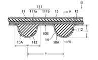
- (Embodiment 1) 1 to 6 show a toothed belt B according to the first embodiment.
- the toothed belt B according to the first embodiment is used, for example, as a power transmission member for rotationally driving an overhead camshaft (OHC) using the power of a crankshaft in an automobile engine.
- the toothed belt B according to Embodiment 1 has, for example, a belt length of 700 mm to 2300 mm, a belt width of 10 mm to 40 mm, and a belt thickness of 4.5 mm to 7.0 mm.
- the toothed belt B is a meshing transmission belt in which a plurality of tooth portions 10A are arranged at predetermined pitches on the inner peripheral side.
- the tooth portion 10 ⁇ / b> A is a so-called round tooth having a semicircular ridge formed in a side view shape so as to extend in the belt width direction.
- the tooth height H of the tooth part 10A is defined by the dimension from the tooth bottom part 10B to the tip of the tooth part 10A between a pair of tooth parts 10A adjacent to each other in the belt length direction, for example, 2.5 mm or more and 4.0 mm. It is as follows.
- the tooth width W of the tooth portion 10A is defined by the dimension between the ends of a pair of tooth bottom portions 10B adjacent to each other across the tooth portion 10A in the belt length direction, and is, for example, 4.5 mm or more and 8.0 mm or less.
- the tooth pitch P of the tooth portion 10A is, for example, not less than 6.0 mm and not more than 10.0 mm.
- the tooth portion 10A may have other shapes such as a trapezoidal tooth, or may be a helical tooth formed so as to extend in a direction inclined with respect to the belt width direction.
- the toothed belt B according to Embodiment 1 includes a belt body 11, a core wire 12, a back reinforcing cloth 13, and a tooth portion reinforcing cloth 14.
- the belt main body 11 is made of rubber and has a back rubber part 111 and a plurality of tooth rubber parts 112.
- the back rubber part 111 is formed in an endless flat belt shape.
- the thickness of the back rubber part 111 is, for example, not less than 1.5 mm and not more than 4.0 mm.
- the plurality of tooth rubber portions 112 are arranged on the inner peripheral side of the back rubber portion 111 at a predetermined pitch corresponding to the tooth portion 10A, and each is formed in a shape corresponding to the tooth portion 10A. And provided integrally with the back rubber part 111.
- the height h of the tooth rubber part 112 is defined by the dimension from the innermost peripheral part of the core wire 12 embedded in the back rubber part 111 to the tip of the tooth rubber part 112, for example, 2.5 mm or more and 4.0 mm or less. is there.
- the core wire 12 is embedded in a surface layer on the inner peripheral side of the back rubber part 111 of the belt body 11 so as to form a spiral having a pitch in the belt width direction and extending in the circumferential direction.
- the core wire 12 is composed of a twisted yarn formed of glass fiber, aramid fiber, carbon fiber, metal fiber or the like.
- the core 12 is preferably provided so that the S twisted yarn and the Z twisted yarn form a double helix, but may be composed of a single S twisted yarn or a Z twisted yarn.
- the diameter of the core wire 12 is, for example, not less than 0.5 mm and not more than 2.5 mm.
- the gap between the core wires 12 adjacent to each other in the belt width direction is substantially constant, and is, for example, not less than 0.5 mm and not more than 3.0 mm.
- the back reinforcing cloth 13 is pasted so as to cover the outer peripheral surface of the back rubber part 111 of the belt main body 11.
- the tooth portion reinforcing cloth 14 is pasted so as to cover the inner peripheral surface of the belt body 11 on which the plurality of tooth rubber portions 112 are provided. Accordingly, the tooth rubber portion 112 is covered with the tooth portion reinforcing cloth 14 to constitute each tooth portion 10A.
- the core wire 12 embedded in the back rubber portion 111 of the belt main body 11 is disposed immediately inside the tooth portion reinforcing cloth 14.
- the back reinforcing cloth 13 and the tooth reinforcing cloth 14 are made of, for example, a woven fabric, a knitted fabric, a non-woven fabric, or the like formed of yarns such as nylon fibers (polyamide fibers), polyester fibers, aramid fibers, and cotton.
- the back reinforcing cloth 13 and the tooth part reinforcing cloth 14 are preferably made of nylon fiber woven cloth.
- the back reinforcing cloth 13 and the tooth part reinforcing cloth 14 preferably have elasticity, such as a woven cloth in which weft processing is applied to the weft.
- the back reinforcing cloth 13 and the tooth reinforcing cloth 14 are bonded to the belt main body 11 by being soaked in a so-called RFL aqueous solution and then heated, soaked in a low-viscosity rubber paste and dried, and high It is preferable that one or two or more types of adhesion treatment is applied among coating treatments in which a rubber paste having a viscosity is applied to the surface of the belt body 11 and dried.
- the back reinforcing cloth 13 and the tooth part reinforcing cloth 14 may be subjected to a base treatment that is heated after being immersed in an epoxy solution or an isocyanate solution before the adhesion treatment.
- the thickness of the back reinforcing cloth 13 and the tooth reinforcing cloth 14 is, for example, not less than 0.3 mm and not more than 2 mm.
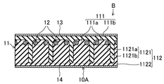
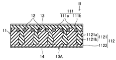
- the belt body 11 is formed of a first rubber composition having a relatively high rubber hardness and a second rubber composition having a relatively low rubber hardness.
- the back rubber portion 111 of the belt main body 11 includes a plurality of core wire-covered rubber portions 111a and other back rubber portions 111b.
- the plurality of core wire-covered rubber portions 111a are arranged at intervals in the belt width direction.
- Each of the plurality of core wire-covered rubber portions 111 a is provided so that one core wire 12 is embedded and covers the core wire 12.
- the core wire-covered rubber portion 111a is formed of a high hardness first rubber composition.
- the back rubber part 111b constitutes a back layer of the back rubber part 111, and a back reinforcing cloth 13 is provided.
- the back rubber portion 111b is formed of a low hardness second rubber composition.
- Each of the plurality of tooth rubber portions 112 of the belt main body 11 includes an inner rubber portion 1121 and a surface rubber portion 1122 provided so as to cover the inner peripheral surface thereof.
- the internal rubber portion 1121 is configured by alternately laminating high hardness rubber layers 1121a and low hardness rubber layers 1121b in the belt width direction.
- the high-hardness rubber layer 1121a is provided corresponding to each of the plurality of core wire-covered rubber portions 111a of the back rubber portion 111 in the belt width direction.
- the high-hardness rubber layer 1121a is formed of the same high-hardness first rubber composition as the core wire-covered rubber portion 111a of the back rubber portion 111. Therefore, the high-hardness rubber layer 1121a is configured continuously with the corresponding core wire-covered rubber portion 111a.
- the low hardness rubber layer 1121b is provided corresponding to the gap between the adjacent core wires 12 in the belt width direction.
- the low-hardness rubber layer 1121b is formed of the same low-hardness second rubber composition as the back rubber part 111b of the back rubber part 111, and is thus configured continuously with the back rubber part 111b. All the low-hardness rubber layers 1121b are connected via the back rubber portion 111b.
- Each of the high-hardness rubber layer 1121a and the low-hardness rubber layer 1121b may have a substantially constant layer thickness in the belt cross-section along the belt thickness direction.
- the layer thickness of the high hardness rubber layer 1121a is, for example, not less than 0.5 mm and not more than 3.0 mm.
- the layer thickness of the low hardness rubber layer 1121b is, for example, not less than 0.5 mm and not more than 3.0 mm.
- the low-hardness rubber layer 1121b is formed so as to hang down from the gap between the core wires 12 adjacent to each other in the belt width direction.
- the shape of the low hardness rubber layer 1121b in the longitudinal section of the belt is preferably a semicircular shape corresponding to the shape of the tooth rubber portion 112.
- the average dimension l from the innermost peripheral portion of the core wire 12 embedded in the back rubber portion 111 to the tip of the low hardness rubber layer 1121b is determined from the viewpoint of obtaining excellent high load durability and impact resistance described later.
- the height h of the rubber part 112 is preferably 30% or more, more preferably 50% or more, and even more preferably 70% or more.
- the surface rubber portion 1122 is formed of the same high hardness first rubber composition as the core wire covering rubber portion 111a and the high hardness rubber layer 1121a. Therefore, the surface rubber portion 1122 is continuous with the high hardness rubber layer 1121a of the inner rubber portion 1121. Configured. All the core wire covering rubber portions 111a and the high hardness rubber layer 1121a are connected via the surface rubber portion 1122.
- the thickness of the surface rubber portion 1122 is, for example, not less than 0.5 mm and not more than 4.0 mm.
- the first and second rubber compositions are obtained by heating and pressurizing the first and second uncrosslinked rubber compositions in which various rubber compounding agents are blended in the rubber component, and the rubber component is crosslinked by the crosslinking agent. is there.
- the rubber component of the first and second rubber compositions examples include hydrogenated acrylonitrile rubber (hereinafter referred to as “H-NBR”) and H-NBR reinforced by finely dispersing an unsaturated metal salt such as zinc methacrylate. (Hereinafter referred to as “reinforced H-NBR”), ethylene- ⁇ -olefin elastomers such as chlorosulfonated polyethylene rubber, chloroprene rubber, ethylene propylene diene terpolymer (EPDM), and the like. It is preferable to use one or more of these rubber components.
- the first and second rubber compositions preferably include the same rubber component.
- the rubber component of the first and second rubber compositions preferably contains at least one of H-NBR and reinforced H-NBR. More preferably, the rubber component of the high hardness first rubber composition is a blend rubber of H-NBR and reinforced H-NBR, and the rubber component of the low hardness second rubber composition is only H-NBR.
- rubber compounding agents examples include processing aids, vulcanization acceleration aids, anti-aging agents, reinforcing materials, plasticizers, co-crosslinking agents, short fibers, and crosslinking agents.
- processing aids include stearic acid, polyethylene wax, and fatty acid metal salts. It is preferable to use one or more of these processing aids.
- the content of the processing aid is, for example, 0.3 parts by mass or more and 0.7 parts by mass or less with respect to 100 parts by mass of the rubber component.
- the vulcanization acceleration aid examples include metal oxides such as zinc oxide (zinc white) and magnesium oxide, metal carbonates, fatty acids and derivatives thereof. It is preferable to use one kind or two or more kinds of vulcanization acceleration aids.
- the content of the vulcanization acceleration aid is, for example, 3 parts by mass or more and 15 parts by mass or less with respect to 100 parts by mass of the rubber component.
- the antiaging agent examples include benzimidazole type, aromatic secondary amine type, amine-ketone type and the like. It is preferable to use one or more of these antiaging agents.
- the content of the antioxidant is, for example, 1.5 parts by mass or more and 3.5 parts by mass or less with respect to 100 parts by mass of the rubber component.
- Reinforcing materials include carbon black, calcium carbonate, silica and the like. It is preferable to use one or more of these reinforcing materials.
- Examples of carbon black include channel black; furnace black such as SAF, ISAF, N-339, HAF, N-351, MAF, FEF, SRF, GPF, ECF, and N-234; thermal black such as FT and MT; Examples include acetylene black. It is preferable to use one or more of these carbon blacks.
- the content of carbon black is, for example, from 0.1 parts by weight to 50 parts by weight with respect to 100 parts by weight of the rubber component.
- the content thereof is, for example, 5 parts by mass or more and 15 parts by mass or less with respect to 100 parts by mass of the rubber component.
- silica is used as the reinforcing material, the content thereof is, for example, 10 parts by mass or more and 30 parts by mass or less with respect to 100 parts by mass of the rubber component.
- plasticizer examples include polyether esters, dialkyl sebacates such as dioctyl sebacate (DOS), dialkyl phthalates such as dibutyl phthalate (DBP) and dioctyl phthalate (DOP), and dialkyl adipates such as dioctyl adipate (DOA). Can be mentioned. It is preferable to use one or more of these plasticizers. Content of a plasticizer is 3 to 15 mass parts with respect to 100 mass parts of rubber components, for example.
- DOS dioctyl sebacate
- DBP dibutyl phthalate
- DOP dioctyl phthalate
- DOA dioctyl adipate
- co-crosslinking agent examples include trimethylolpropane trimethacrylate, m-phenylene dimaleimide, zinc dimethacrylate, triallyl isocyanurate and the like. It is preferable to use one or more of these co-crosslinking agents.
- the content of the co-crosslinking agent is, for example, 1 part by mass or more and 8 parts by mass or less with respect to 100 parts by mass of the rubber component.
- Examples of the short fibers include aramid short fibers, nylon short fibers, polyester short fibers, and the like.
- the length of the short fiber is, for example, 1 mm or more and 3 mm or less. It is preferable to use one or more of these short fibers.
- the content of the short fiber is, for example, 1 part by mass or more and 5 parts by mass or less with respect to 100 parts by mass of the rubber component.
- the crosslinking agent examples include sulfur and organic peroxides.
- a crosslinking agent only sulfur may be used, only an organic peroxide may be used, and furthermore, both of them may be used in combination.
- the combined use of sulfur and organic peroxide is preferable.
- the amount of the crosslinking agent is, for example, 0.1 to 0.7 parts by mass of sulfur with respect to 100 parts by mass of the rubber component.
- the organic peroxide is 2 parts by mass or more and 5 parts by mass or less.
- the rubber hardness of the first rubber composition is higher than that of the second rubber composition.
- Rubber hardness of the first rubber composition from the viewpoint of obtaining excellent high load durability and impact resistance will be described later, preferably not more than 85H A more 95H A, more preferably not more than 88H A more 94H A.
- Rubber hardness of the second rubber composition from the same viewpoint, preferably less 50H A more 80H A, more preferably not more than 65H A more 75H A. From the same viewpoint, the difference in rubber hardness between the first and second rubber compositions is preferably 5 HA or more and 45 HA or less, more preferably 13 HA or more and 29 HA or less.
- the ratio of the rubber hardness of the first rubber composition to the rubber hardness of the second rubber composition is preferably 1.1 or more and 1.9 or less, more preferably 1.2 or more and 1.5 or less. More preferably, it is 1.2 or more and 1.4 or less.
- Tensile strength T B at 25 ° C. of Retsuri direction of the first rubber composition from the viewpoint of obtaining excellent high load durability and impact resistance will be described later, preferably 20MPa or more 40MPa or less, and more preferably at least 25MPa 35 MPa or less.
- Tensile strength T B at 25 ° C. of Retsuri direction of the second rubber composition from the same viewpoint, preferably 15MPa or more 35MPa or less, more preferably 30MPa or more 20 MPa.
- Tensile strength T B of the first rubber composition is preferably high than the tensile strength T B of the second rubber composition.
- Elongation E B at Retsuri direction 25 ° C. of the first rubber composition from the viewpoint of obtaining excellent high load durability and impact resistance below, preferably 300% to 100% or less, more preferably 150% More than 250%.
- Elongation E B at Retsuri direction 25 ° C. of the second rubber composition from the same viewpoint, it is preferably 550% or more 350% or less, more preferably 500% or less than 400%.
- Elongation E B of the first rubber composition is preferably less than the elongation E B of the second rubber composition.
- the tensile stress M 100 at 100% at 25 ° C. in the direction of the first rubber composition is preferably from 10 MPa to 30 MPa, more preferably from the viewpoint of obtaining excellent high load durability and impact resistance described later. 15 MPa or more and 25 MPa or less. From the same viewpoint, the tensile stress M 100 at 100% at 25 ° C. in the direction of the second rubber composition is preferably 1.5 MPa to 5.5 MPa, more preferably 2.5 MPa to 4.5 MPa. It is. 100% tensile stress M 100 of the first rubber composition is preferably higher than the stress M 100 Tensile at 100% of the second rubber composition.
- the rubber hardness of the first and second rubber compositions is measured using a type A durometer based on JIS K6253.
- the tensile strength T B , elongation E B , and 100% tensile stress M 100 in the row direction of the first and second rubber compositions are measured by a tensile test based on JIS K6301.
- the toothed belt B according to the first embodiment having the above configuration is wound between a crankshaft pulley and an OHC pulley and used as a power transmission member for transmitting the former power to the latter.
- the toothed belt B According to the toothed belt B according to the first embodiment, the tooth rubber portion 112 is relatively relative to the high hardness rubber layer 1121a formed of the first rubber composition having relatively high rubber hardness.
- a low-hardness rubber layer 1121b formed of a second rubber composition having a low rubber hardness has internal rubber portions 1121 that are alternately laminated in the belt width direction, and covers the inner peripheral surface thereof.
- the surface rubber portion 1122 provided is formed of the first rubber composition having the same relatively high rubber hardness as the high hardness rubber layer 1121a, thereby obtaining excellent high load durability and impact resistance. Can do. This is because deformation of the tooth rubber portion 112 is suppressed by the high hardness surface rubber portion 1122, so that it is possible to avoid the occurrence of peak distortion that directly connects to the tooth chip in the tooth rubber portion 112.
- the internal rubber portion 1121 has an alternately laminated structure of the high-hardness rubber layer 1121a and the low-hardness rubber layer 1121b, so that the followability to the deformation of the tooth rubber portion 112 is enhanced and the load distribution applied to the tooth rubber portion 112 is increased. This is presumed to be because it is possible to avoid the occurrence of peak stress that is directly connected to the tooth chipping in the tooth rubber portion 112.
- the manufacturing method of the toothed belt B according to Embodiment 1 includes a material preparation process, a molding process, a crosslinking process, and a finishing process.
- a predetermined rubber component is masticated, and various rubber compounding agents are added thereto and kneaded to obtain a first uncrosslinked rubber composition that forms a first rubber composition having a relatively high rubber hardness.
- the sheet-like 1st uncrosslinked rubber composition 151 is produced by carrying out the calendar shaping
- a second uncrosslinked rubber composition that forms a second rubber composition having a relatively low rubber hardness by kneading a predetermined rubber component and adding and kneading various rubber compounding agents therein. Get. Then, the obtained second uncrosslinked rubber composition is calendered to produce a sheet-like second uncrosslinked rubber composition 152.
- FIG. 7 shows the belt mold 20.
- the belt forming die 20 is cylindrical and has an outer peripheral surface in which a plurality of tooth portion forming grooves 21 formed so as to extend in the axial direction are arranged at intervals in the circumferential direction.
- a cylindrical tooth portion reinforcing cloth 14 is placed on the outer peripheral surface of the belt forming die 20, and the core wire 12 is wound spirally from above.
- the core wire 12 is composed of S-twisted yarn and Z-twisted yarn
- the distance between the centers of the S-twisted yarn and the Z-twisted yarn is made constant, and the distance between the centers.
- These S-twisted yarns and Z-twisted yarns may be wound in a double helix shape at a pitch twice as large as the above.
- what is necessary is just to wind the core wire 12 in a helical form with a fixed pitch, when comprising with the single S twist yarn or Z twist yarn.
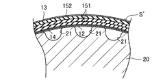
- a sheet-like first uncrosslinked rubber composition 151 and a sheet-like second uncrosslinked rubber composition 152 are wound around the sheet in order.
- the first uncrosslinked rubber composition 151 is preferably wound thicker than the second uncrosslinked rubber composition 152 from the viewpoint of obtaining excellent high load durability and impact resistance.
- the ratio of the volume of the first uncrosslinked rubber composition 151 to the volume of the second uncrosslinked rubber composition 152 is preferably greater than 1, more preferably 1.5 or more, and preferably 3.5 or less, more preferably 2.5 or less. It is preferable to use the sheet-like first and second uncrosslinked rubber compositions 151 and 152 so that the alignment direction corresponds to the belt length direction.
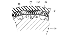
- FIG. 8B an uncrosslinked slab S ′ on the belt mold 20 is covered with a rubber sleeve 22, which is placed in a vulcanizing can and sealed, and high-temperature and high-pressure steam is put into the vulcanizing can. Fill and hold for a predetermined molding time.
- the first and second uncrosslinked rubber compositions 151 and 152 are passed between the core wires 12 as shown in FIG. While pressing the reinforcing portion, the reinforcing portion is caused to flow into each of the plurality of tooth portion forming grooves 21 of the belt mold 20 and to be bridged.
- the core wire 12, the back reinforcing cloth 13, and the tooth reinforcing cloth 14 are combined and integrated, and finally a cylindrical belt slab S is formed as shown in FIG. 8D.
- the first uncrosslinked rubber composition 151 is 100 ° C. than the second uncrosslinked rubber composition 152.
- the Mooney viscosity at is preferably high.
- the Mooney viscosity at 100 ° C. of the first uncrosslinked rubber composition 151 is preferably 40 ML 1 + 4 (100 ° C.) or more, more preferably 50 ML 1 + 4 (100 ° C.) or more, and preferably 70 ML 1 + 4 (100 ° C.) or less. More preferably, it is 60 ML 1 + 4 (100 ° C.) or less.
- the ratio of the Mooney viscosity at 100 ° C. of the first uncrosslinked rubber composition 151 to the Mooney viscosity at 100 ° C. of the second uncrosslinked rubber composition 152 is preferably greater than 1 and less than or equal to 2.0, more preferably 1. 5 or less. Mooney viscosity is measured based on JIS K6300.
- ⁇ Finishing process> The inside of the vulcanizing can is depressurized to release the seal, the belt slab S molded between the belt mold 20 and the rubber sleeve 22 is taken out, removed from the mold, and cut into a predetermined width to cut the toothed belt B. obtain.
- Embodiment 2 9 and 10 show a toothed belt B according to the second embodiment.
- the part of the same name as Embodiment 1 is shown with the same code
- FIG. 1 is a diagrammatic representation of Embodiment 1.
- the toothed belt B according to the second embodiment has a relatively small gap and a relatively large gap between the core wires 12 adjacent to each other in the belt width direction. Specifically, relatively small gaps and relatively large gaps between the core wires 12 are alternately arranged in the belt width direction. In the portion where the gap between the core wires 12 is relatively small, the core wire covering rubber portion 111a of the back rubber portion 111 is embedded with a pair of core wires 12 adjacent to each other in the belt width direction across the small gap. And is provided so as to cover the pair of core wires 12.
- the low hardness rubber layer 1121b of the inner rubber portion 1121 of the tooth rubber portion 112 is formed so as to hang down from the large gap to the inner peripheral side in the belt cross section. ing. That is, in the toothed belt B according to the second embodiment, the low-hardness rubber layer 1121b is not provided corresponding to the relatively small gap between the core wires 12, but the high-hardness rubber layer 1121a is provided. The low hardness rubber layer 1121b is provided corresponding to the relatively large gap between the core wires 12.
- the relatively small gap between the core wires 12 is, for example, not less than 0.01 mm and not more than 0.5 mm.
- the relatively large gap between the core wires 12 is, for example, not less than 0.5 mm and not more than 1.5 mm.
- the ratio of the large gap to the relatively small gap between the core wires 12 is preferably 0.6 or more and 100 or less.
- the core wire 12 is composed of S-twisted yarn and Z-twisted yarn, and the center distance between the S-twisted yarn and Z-twisted yarn is constant when the uncrosslinked slab S ′ is formed.
- the S-twisted yarn and the Z-twisted yarn may be wound in a double spiral shape at a pitch larger than twice the center distance. Accordingly, in this case, the pair of core wires 12 covered with the same core wire-covered rubber portion 111a becomes an S twist yarn and a Z twist yarn.
- the high-hardness rubber layer 1121a and the low-hardness rubber layer 1121b have a configuration in which the layer thickness in the belt cross-section is substantially constant along the belt thickness direction.
- the layer thickness in the belt cross section gradually increases from the base end side along the belt thickness direction.
- the cross-sectional shape which becomes suddenly small at the tip after becoming a water droplet shape may be formed.
- Such a configuration can be obtained by adjusting the fluidity of the first and second uncrosslinked rubber compositions 151 and 152 by blending design.
- the low hardness rubber layer 1121b is provided corresponding to the gaps between all the core wires 12.
- the present invention is not limited to this, and as shown in FIG. A portion where the low-hardness rubber layer 1121b is not provided may be included corresponding to the gap between the two.
- the back reinforcing cloth 13 is provided.
- the present invention is not particularly limited thereto, and the back rubber part 111 is exposed without the back reinforcing cloth 13. Also good.
- this rubber component for 100 parts by mass of this rubber component, 5 parts by mass of zinc oxide as a vulcanization accelerator, 2.5 parts by mass of anti-aging agent, 20 parts by mass of carbon black as a reinforcing material, 20 parts by mass of silica, 5 parts by mass of plasticizer, 6 parts by mass of co-crosslinking agent, 3 parts by mass of aramid short fibers (1 mm), 0.3 part by mass of sulfur of the crosslinking agent, and 3.2 mass of organic peroxide of the crosslinking agent
- the first uncrosslinked rubber composition was prepared by charging and mixing the parts.
- H-NBR (Second uncrosslinked rubber composition) H-NBR (trade name: Zetpol 2000, manufactured by Nippon Zeon Co., Ltd.) as a rubber component is introduced into a chamber of a closed Banbury mixer and masticated. Then, with respect to 100 parts by mass of the rubber component, a processing aid of 0.
- a second uncrosslinked rubber composition was prepared by charging and mixing 3 parts by mass of a crosslinking agent, 0.5 parts by mass of sulfur as a crosslinking agent, and 3.2 parts by mass of an organic peroxide as a crosslinking agent.
- Each of the first and second uncrosslinked rubber compositions was molded into a sheet by calendar molding. Using these sheet-like first and second uncrosslinked rubber compositions (67% by volume of the first uncrosslinked rubber composition and 33% by volume of the second uncrosslinked rubber composition) and having no back reinforcing fabric Except for the above, a toothed belt having the same configuration as that of the first embodiment was produced and used as an example.
- the belt length is 1381 mm
- the belt width is 25 mm
- the belt thickness is 6.3 mm.
- the tooth height H is 3.5 mm
- the tooth width W is 7.4 mm
- the tooth pitch P is 9.525 mm.
- the height h of the tooth rubber part was 3.0 mm.
- the average thickness of the high hardness rubber layer was 1.5 mm
- the average thickness of the low hardness rubber layer was 1.5 mm.
- the average thickness of the surface rubber portion was 1.0 mm.
- the dimension l from the innermost peripheral portion of the core wire to the tip of the low hardness rubber layer was 67% on average with respect to the height h of the tooth rubber portion.
- a glass fiber twisted yarn subjected to adhesion treatment was used for the core wire and a nylon 6,6 fiber woven fabric subjected to adhesion treatment was used for the tooth reinforcement fabric.
- Comparative Examples 1 and 2 A toothed belt was produced in the same manner as in Example except that the belt body was formed using only the sheet-like first uncrosslinked rubber composition, and this was designated as Comparative Example 1. Further, a toothed belt was produced in the same manner as in Example except that the belt body was formed using only the sheet-like second uncrosslinked rubber composition, and this was designated as Comparative Example 2.
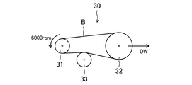
- FIG. 13 shows a pulley layout of a belt running test machine 30 for a high load endurance test.
- the belt running test machine 30 has a drive pulley 31, a driven pulley 32 provided on the right side thereof, and an idler pulley 33 provided on the lower side therebetween.
- a drive pulley 31 On the outer periphery of the drive pulley 31, 21 tooth meshing grooves are provided.
- On the outer periphery of the driven pulley 32 42 tooth-engagement grooves are provided.
- the outer diameter of the idler pulley 33 is 52 mm.
- each toothed belt B of Example and Comparative Examples 1 and 2 it is wound around the drive pulley 31, the driven pulley 32, and the idler pulley 33 of the belt running test machine 30, and the driven pulley 32 is dead to the right by 1200N.
- a belt running test was performed by loading the weight DW and rotating the driving pulley at a rotational speed of 6000 rpm under an atmospheric temperature of 100 ° C. Then, the number of rotations until the toothed belt was damaged was measured.
- FIG. 14 shows a pulley layout of a belt testing machine 40 for an impact resistant vibration test.
- This belt testing machine 40 includes a driving pulley 41, a fixed first driven pulley 42 provided obliquely below the left side, a second driven pulley 43 provided obliquely above the left side, a driving pulley 41, a first pulley Three idler pulleys 44 disposed between the driven pulley 42 and the second driven pulley 43, and the tension provided immediately above the idler pulley 44 between the first driven pulley 42 and the second driven pulley 43. And an imparting pulley 45.
- On the outer periphery of the drive pulley 41 22 tooth-engagement grooves are provided.
- On the outer periphery of the first driven pulley 42 22 tooth-engagement grooves are provided.
- 44 tooth-engagement grooves are provided on the outer periphery of the second driven pulley 43.
- the outer diameter of the idler pulley 44 is 28.5 mm.
- the outer diameter of the tension applying pulley 45 is 67.7 mm.
- the belt tester 40 meshes with the drive pulley 41, the first driven pulley 42, and the second driven pulley 43, and the idler pulley. 44 and the tension applying pulley 45 are wound so that the back surface of the belt comes into contact with each other, and a set weight is loaded by the tension applying pulley 45 so that the belt tension becomes 800 N, and the drive pulley 41 is moved in the forward direction at an ambient temperature of 25 ° C.
- a rotation vibration test is performed in which the rotation direction is changed to the reverse direction when a predetermined load is generated on the drive pulley 41, and the rotation direction is changed to the forward direction again when a predetermined load is generated on the drive pulley 41. went. And the frequency
- Test results The test results are shown in Tables 3 and 4.
- the first rubber composition obtained by crosslinking the first uncrosslinked rubber composition has higher hardness than the second rubber composition obtained by crosslinking the second uncrosslinked rubber composition. It was confirmed that.
- the first uncrosslinked rubber composition forming the first hard rubber composition has a Mooney viscosity at 100 ° C. lower than the second uncrosslinked rubber composition forming the second hard rubber composition. I understand.
- the first rubber composition to crosslink the first uncrosslinked rubber composition than the second rubber composition obtained by crosslinking the second uncrosslinked rubber composition, high strength T B tensile Retsuri direction , small elongation E B, and it can be seen high 100% tensile stress M 100.
- the tooth rubber part is a low hardness rubber formed of a high hardness rubber layer formed of a high hardness first rubber composition and a low hardness second rubber composition.
- An embodiment having an inner rubber portion in which layers are alternately laminated in the belt width direction and a surface rubber portion formed of a high hardness first rubber composition provided so as to cover the inner rubber portion Compared with Comparative Example 1 in which only the first rubber composition with high hardness is formed and Comparative Example 2 in which the tooth rubber part is formed with only the second rubber composition with low hardness, high load durability and impact resistance It turns out that both are excellent.
- the present invention is useful in the technical field of a toothed belt and a manufacturing method thereof.
- Toothed belt S Belt slab S 'Uncrosslinked slab 10A Tooth part 10B Tooth base 11 Belt body 111 Back rubber part 111a Core wire covering rubber part 111b Back rubber part 112 Tooth rubber part 1121 Internal rubber part 1121a High hardness rubber layer 1121b Low Hardness rubber layer 1122 Surface rubber part 12 Core wire 13 Back reinforcing cloth 14 Tooth part reinforcing cloth 151 First uncrosslinked rubber composition 152 Second uncrosslinked rubber composition 20 Belt mold 21 Tooth part forming groove 22 Rubber sleeves 30, 40 Belt running tester 31, 41 Drive pulley 32 Driven pulley 33, 44 Idler pulley 42 First driven pulley 43 Second driven pulley 45 Tensioning pulley
Landscapes
- Engineering & Computer Science (AREA)
- General Engineering & Computer Science (AREA)
- Mechanical Engineering (AREA)
- Textile Engineering (AREA)
- Compositions Of Macromolecular Compounds (AREA)
Abstract
L'invention concerne une courroie crantée (B), dans laquelle les sections de caoutchouc cranté (112) comprennent : une partie interne en caoutchouc (1121) dans laquelle des couches de caoutchouc de dureté élevée (1121a) formées à partir d'une première composition de caoutchouc de dureté de caoutchouc relativement élevée et des couches de caoutchouc de faible dureté formées (1121b) à partir d'une seconde composition de caoutchouc de dureté de caoutchouc relativement faible sont stratifiées en alternance dans la direction de la largeur de la courroie ; et une partie de surface en caoutchouc (1122) disposée de manière à recouvrir la surface circonférentielle interne de la partie interne en caoutchouc (1121) et formée à partir de la même première composition de caoutchouc de dureté de caoutchouc relativement élevée que les couches de caoutchouc de dureté élevée (1121a).
Priority Applications (3)
| Application Number | Priority Date | Filing Date | Title |
|---|---|---|---|
| JP2017516787A JP6158465B1 (ja) | 2016-07-08 | 2017-03-23 | 歯付ベルト及びその製造方法 |
| DE112017003459.0T DE112017003459B4 (de) | 2016-07-08 | 2017-03-23 | Zahnriemen und Herstellungsverfahren für einen solchen Zahnriemen |
| CN201780035854.5A CN109312819B (zh) | 2016-07-08 | 2017-03-23 | 齿形带及其制造方法 |
Applications Claiming Priority (2)
| Application Number | Priority Date | Filing Date | Title |
|---|---|---|---|
| JP2016-136193 | 2016-07-08 | ||
| JP2016136193 | 2016-07-08 |
Publications (1)
| Publication Number | Publication Date |
|---|---|
| WO2018008204A1 true WO2018008204A1 (fr) | 2018-01-11 |
Family
ID=60912053
Family Applications (1)
| Application Number | Title | Priority Date | Filing Date |
|---|---|---|---|
| PCT/JP2017/011794 WO2018008204A1 (fr) | 2016-07-08 | 2017-03-23 | Courroie crantée et procédé de production s'y rapportant |
Country Status (3)
| Country | Link |
|---|---|
| CN (1) | CN109312819B (fr) |
| DE (1) | DE112017003459B4 (fr) |
| WO (1) | WO2018008204A1 (fr) |
Cited By (5)
| Publication number | Priority date | Publication date | Assignee | Title |
|---|---|---|---|---|
| WO2017154978A1 (fr) * | 2016-03-09 | 2017-09-14 | 東洋紡株式会社 | Feuille conductrice élastique et pâte destinée à la formation d'une feuille conductrice élastique |
| US10716912B2 (en) | 2015-03-31 | 2020-07-21 | Fisher & Paykel Healthcare Limited | User interface and system for supplying gases to an airway |
| US11324908B2 (en) | 2016-08-11 | 2022-05-10 | Fisher & Paykel Healthcare Limited | Collapsible conduit, patient interface and headgear connector |
| JP2023018654A (ja) * | 2021-07-27 | 2023-02-08 | 三ツ星ベルト株式会社 | 歯付ベルトおよびその製造方法 |
| TWI811040B (zh) * | 2021-07-27 | 2023-08-01 | 日商三星皮帶股份有限公司 | 齒型皮帶及其製造方法 |
Citations (3)
| Publication number | Priority date | Publication date | Assignee | Title |
|---|---|---|---|---|
| JP2008115938A (ja) * | 2006-11-02 | 2008-05-22 | Gates Unitta Asia Co | 歯付きベルト |
| JP2010265920A (ja) * | 2009-05-12 | 2010-11-25 | Toyota Motor Corp | 歯付ベルト |
| WO2015045255A1 (fr) * | 2013-09-26 | 2015-04-02 | バンドー化学株式会社 | Courroie trapézoïdale et procédé de fabrication |
Family Cites Families (9)
| Publication number | Priority date | Publication date | Assignee | Title |
|---|---|---|---|---|
| US4504342A (en) | 1983-06-09 | 1985-03-12 | Dayco Corporation | Belt construction and method of making same |
| US4626232A (en) | 1984-10-09 | 1986-12-02 | Dayco Corporation | Belt construction and method of making the same |
| GB2349113B (en) * | 1999-04-21 | 2003-07-02 | Gates Corp | Wear resistant belts and a process for their manufacture |
| US6609990B2 (en) | 2001-07-18 | 2003-08-26 | The Gates Corporation | Power transmission belt and method |
| JP2003314622A (ja) | 2002-04-17 | 2003-11-06 | Mitsuboshi Belting Ltd | 歯付ベルトとその製造方法 |
| JP4995930B2 (ja) | 2009-02-13 | 2012-08-08 | ゲイツ・ユニッタ・アジア株式会社 | 歯付きベルト |
| JP5597545B2 (ja) * | 2009-10-13 | 2014-10-01 | ゲイツ・ユニッタ・アジア株式会社 | 歯付きベルト |
| DE202012102734U1 (de) * | 2012-07-20 | 2012-08-22 | Ningbo Gul Tz Rubber Belt Co., Ltd. | Zahnriemen |
| JP6275585B2 (ja) | 2013-08-30 | 2018-02-07 | 三ツ星ベルト株式会社 | 歯付ベルト |
-
2017
- 2017-03-23 WO PCT/JP2017/011794 patent/WO2018008204A1/fr active Application Filing
- 2017-03-23 DE DE112017003459.0T patent/DE112017003459B4/de active Active
- 2017-03-23 CN CN201780035854.5A patent/CN109312819B/zh active Active
Patent Citations (3)
| Publication number | Priority date | Publication date | Assignee | Title |
|---|---|---|---|---|
| JP2008115938A (ja) * | 2006-11-02 | 2008-05-22 | Gates Unitta Asia Co | 歯付きベルト |
| JP2010265920A (ja) * | 2009-05-12 | 2010-11-25 | Toyota Motor Corp | 歯付ベルト |
| WO2015045255A1 (fr) * | 2013-09-26 | 2015-04-02 | バンドー化学株式会社 | Courroie trapézoïdale et procédé de fabrication |
Cited By (7)
| Publication number | Priority date | Publication date | Assignee | Title |
|---|---|---|---|---|
| US10716912B2 (en) | 2015-03-31 | 2020-07-21 | Fisher & Paykel Healthcare Limited | User interface and system for supplying gases to an airway |
| US11904097B2 (en) | 2015-03-31 | 2024-02-20 | Fisher & Paykel Healthcare Limited | User interface and system for supplying gases to an airway |
| WO2017154978A1 (fr) * | 2016-03-09 | 2017-09-14 | 東洋紡株式会社 | Feuille conductrice élastique et pâte destinée à la formation d'une feuille conductrice élastique |
| US11324908B2 (en) | 2016-08-11 | 2022-05-10 | Fisher & Paykel Healthcare Limited | Collapsible conduit, patient interface and headgear connector |
| JP2023018654A (ja) * | 2021-07-27 | 2023-02-08 | 三ツ星ベルト株式会社 | 歯付ベルトおよびその製造方法 |
| JP7235919B2 (ja) | 2021-07-27 | 2023-03-08 | 三ツ星ベルト株式会社 | 歯付ベルトおよびその製造方法 |
| TWI811040B (zh) * | 2021-07-27 | 2023-08-01 | 日商三星皮帶股份有限公司 | 齒型皮帶及其製造方法 |
Also Published As
| Publication number | Publication date |
|---|---|
| CN109312819A (zh) | 2019-02-05 |
| DE112017003459T5 (de) | 2019-03-21 |
| DE112017003459B4 (de) | 2023-07-06 |
| CN109312819B (zh) | 2019-06-04 |
Similar Documents
| Publication | Publication Date | Title |
|---|---|---|
| WO2018008204A1 (fr) | Courroie crantée et procédé de production s'y rapportant | |
| JP6221011B1 (ja) | 歯付ベルト | |
| JP6145170B2 (ja) | Vベルト及びその製造方法 | |
| JP6101677B2 (ja) | 摩擦伝動ベルト | |
| WO2010109533A1 (fr) | Courroie plate | |
| WO2010007741A1 (fr) | Courroie de transmission | |
| WO2014006916A1 (fr) | Courroie de transmission | |
| KR20110080168A (ko) | 마찰전동벨트 | |
| WO2019069842A1 (fr) | Courroie de transmission | |
| JP6609395B1 (ja) | 歯付ベルト | |
| EP4053429A1 (fr) | Courroie à nervures en v | |
| JP5060248B2 (ja) | 平ベルト | |
| JP6158465B1 (ja) | 歯付ベルト及びその製造方法 | |
| JP2018165514A (ja) | 歯付ベルト | |
| JP2007262147A (ja) | ゴム組成物及び伝動ベルト | |
| WO2024009664A1 (fr) | Courroie crantée | |
| JP7406050B1 (ja) | 歯付ベルト | |
| WO2024185792A1 (fr) | Courroie dentée et système de transmission de puissance | |
| WO2024185788A1 (fr) | Courroie dentée et système de transmission | |
| JP7562406B2 (ja) | 歯付ベルト | |
| JP6383135B1 (ja) | 伝動ベルト及びその製造方法 | |
| JP6603350B2 (ja) | ローエッジvベルト | |
| JPWO2017033392A1 (ja) | 摩擦伝動ベルト | |
| JP2022152628A (ja) | 伝動ベルト | |
| WO2010004733A1 (fr) | Courroie plate |
Legal Events
| Date | Code | Title | Description |
|---|---|---|---|
| ENP | Entry into the national phase |
Ref document number: 2017516787 Country of ref document: JP Kind code of ref document: A |
|
| 121 | Ep: the epo has been informed by wipo that ep was designated in this application |
Ref document number: 17823812 Country of ref document: EP Kind code of ref document: A1 |
|
| 122 | Ep: pct application non-entry in european phase |
Ref document number: 17823812 Country of ref document: EP Kind code of ref document: A1 |