WO2018003873A1 - 切削インサート - Google Patents
切削インサート Download PDFInfo
- Publication number
- WO2018003873A1 WO2018003873A1 PCT/JP2017/023789 JP2017023789W WO2018003873A1 WO 2018003873 A1 WO2018003873 A1 WO 2018003873A1 JP 2017023789 W JP2017023789 W JP 2017023789W WO 2018003873 A1 WO2018003873 A1 WO 2018003873A1
- Authority
- WO
- WIPO (PCT)
- Prior art keywords
- blade
- corner
- wiper blade
- honing
- flank
- Prior art date
- Legal status (The legal status is an assumption and is not a legal conclusion. Google has not performed a legal analysis and makes no representation as to the accuracy of the status listed.)
- Ceased
Links
Images



Classifications
-
- B—PERFORMING OPERATIONS; TRANSPORTING
- B23—MACHINE TOOLS; METAL-WORKING NOT OTHERWISE PROVIDED FOR
- B23B—TURNING; BORING
- B23B27/00—Tools for turning or boring machines; Tools of a similar kind in general; Accessories therefor
- B23B27/14—Cutting tools of which the bits or tips or cutting inserts are of special material
Definitions
- the present invention relates to a cutting insert that is attached to a cutting edge replaceable bite or the like and performs turning of a work material.
- Patent Document 1 proposes a cutting insert in which a nose cutting edge is divided into at least five circular segments for the purpose of improving the smoothness of a machined surface.
- the bisector of the nose radius intersects the first segment having the first curvature radius re, and the second curvature radius r2 is provided on both sides of the first segment.
- the second segment having the third curvature radius r3 is joined to the second segment, and the first to third curvature radii re, r2, and r3 have a relationship of r3> re> r2. have.
- Patent Document 2 also discloses a finishing blade (corner blade) that is cut into a work material in advance for the purpose of obtaining a finished surface with good surface roughness, and a work piece following this finishing blade. It has a super-finishing blade that finishes the material, and the super-finishing blade protrudes a predetermined amount from the position of the finishing blade in the direction of increasing the cutting depth, and extends from the burnishing part extending in the tool feed direction to the burnishing part There has been proposed a cutting insert that includes a baffle and is configured such that the superfinished blade burns the finished surface while removing the work-affected layer on the surface processed by the finished blade.
- Patent Document 3 also comprises a polygonal plate-like body having an upper surface as a rake surface, a lower surface as a seating surface, and a side surface as a flank for the purpose of improving the finished surface roughness of the work material.
- a cutting edge is formed on a ridge between the rake face and the flank, and a corner cutting edge and a Sarae blade connected to both ends of the corner cutting edge at a corner portion where the ridge edge of the polygonal plate-like body intersects
- a horizontal cutting blade connected to the Sarae blade and a cutting insert is proposed in which an arc-shaped protruding portion that protrudes toward the rake face side is formed on the Sarae blade.
- the above-described nose cutting blade divided into at least five circular segments is arranged on one plane as shown in FIG. .
- the wiper blade of the third segment that is apart from the corner blade (first segment) rubs against the work material and causes an increase in cutting resistance, resulting in unstable cutting and an inner diameter.
- chatter vibrations and waviness of the machined surface may occur during machining or outside diameter machining of a small-diameter work material.
- Such a problem becomes more conspicuous in the cutting insert described in Patent Document 2 in which the super-finishing blade (wiper blade) is configured to burnish, that is, rub, the finished surface.
- a cutting insert in which an arc-shaped protruding portion protruding to the rake face side is formed on a Sarae blade (wiper blade) by a sintered material such as cemented carbide When manufacturing by sintering, it is difficult to polish a general ISO standard cutting insert to form the protrusion. For this reason, it is necessary to form a recess corresponding to the protruding portion in the die for press-molding the green compact before being sintered into the cutting insert, and a dedicated die is required, resulting in an increase in cost. It will be. Furthermore, for example, such a protruding portion cannot be formed in a cutting insert in which a cBN sintered body or a diamond sintered body is disposed in a portion from a corner blade to a wiper blade.
- the present invention has been made under such a background, and in a cutting insert provided with a wiper blade, it is possible to prevent an increase in cost and also to a cutting insert provided with a cBN sintered body and a diamond sintered body.
- a cutting insert that can be applied and can stably perform cutting in the inner diameter machining and the outer diameter machining of small-diameter work materials by preventing an increase in cutting resistance due to rubbing against the work material even in high-feed machining. The purpose is to provide.
- a cutting insert scoops the polygonal surface at the corner portion of the polygonal surface of the polygonal plate-like insert body.
- a corner blade having a surface and having a convex curve shape in a plan view facing the rake face is formed, and a side ridge portion of the polygonal surface connected to the corner blade is seen in a plan view facing the rake face.
- a wiper blade having a convex curve shape with a larger radius of curvature than the corner blade is formed, and a chamfer honing surface is formed from the corner blade to the wiper blade. The angle is constant, and the honing width in a plan view facing the rake face is gradually increased as the wiper blade moves away from the corner blade.
- the chamfer honing surface formed from the corner blade to the wiper blade has a constant honing angle, but the honing width in a plan view facing the rake surface is from the corner blade in the wiper blade. Since it gradually increases as the distance increases, the intersection ridge line between the chamfer honing surface of the wiper blade and the flank formed on the side surface arranged around the polygonal surface is opposite to the rake surface as the distance from the corner blade increases. It will incline so that it may go to the polygon surface side.
- such a chamfer honing surface and a wiper blade can be formed by polishing a general ISO standard cutting insert. For this reason, even if the insert body is integrally formed of a sintered material such as cemented carbide, a dedicated mold is not required, and the manufacturing cost of the cutting insert can be suppressed. Further, the present invention can be applied even to a cutting insert in which a cBN sintered body or a diamond sintered body is disposed in a portion from a corner blade to a wiper blade.
- a flank is formed on the side surface of the insert body arranged around the polygonal surface, but at the intersection ridge line between the chamfer honing surface and the flank in the corner blade.
- the intersecting ridge line between the chamfer honing surface and the flank surface in the wiper blade is in a range of 0.0250 mm or less as the distance from the corner blade increases in a direction perpendicular to the polygonal surface on which the rake surface is formed. It is desirable to incline so that it may go to the polygonal surface side opposite to the said rake face.
- this range is a range of 0.0196 mm or less.
- this intersecting ridge line is inclined to face the polygonal surface side opposite to the rake face in a range of 0.0070 mm or more with respect to the intersecting ridge line between the chamfer honing surface and the flank surface in the corner blade. Is desirable.
- a convex curved wiper blade is formed by polishing so as to be in contact with the linear main cutting edge in the general ISO standard cutting insert as described above, and is further protruded in the corner portion so as to be in contact with the wiper blade.
- the tip of the corner blade on the bisector of the corner portion retreats to the inner side of the insert body than before polishing. Therefore, using such a cutting insert, for example, if an NC lathe is used to copy a workpiece, the remaining part of the corner blade will be left behind, so the NC lathe program has been modified. Must.
- a linear straight blade contacting the corner blade and the wiper blade may be formed between the corner blade and the wiper blade in a plan view facing the rake face.
- the present invention it is possible to manufacture at a low cost without requiring a dedicated mold, and also applicable to a cutting insert provided with a cBN sintered body or a diamond sintered body. Yes, by suppressing the wiper blade from rubbing against the work material and suppressing the increase in cutting resistance, chatter vibrations and waviness of the work surface can be achieved even with high-feed inner diameter machining and outer diameter machining of small-diameter work materials. This makes it possible to perform highly accurate and stable cutting.
- FIG. 2 is an enlarged plan view of a corner portion in FIG. 1.
- FIG. 3 is an enlarged side view of a corner portion in FIG. 2.
- VV sectional drawing in FIG. It is WW sectional drawing in FIG.
- XX sectional drawing in FIG. It is YY sectional drawing in FIG.
- the insert body 1 is formed in a polygonal plate shape, specifically, a rhombus flat plate shape having an acute corner portion angle of 80 °, and two polygonal surfaces (rhombus surface) 2; Four rectangular side surfaces 3 arranged around these polygonal surfaces 2 are provided.
- an attachment hole 4 is formed that has a circular cross section centering on the insert center line L passing through the centers of these polygonal surfaces 2 and penetrates the insert body 1.
- the two polygonal surfaces 2 have a planar shape perpendicular to the insert center line L.
- the insert body 1 of the present embodiment is a polygonal surface out of the two polygonal surfaces 2 of the base metal 5 formed in a substantially polygonal plate shape as described above from a hard material such as cemented carbide.
- a hard material such as cemented carbide.
- Two corners C at two acute angles are formed with L-shaped cutouts 5a, and cBN having a hardness higher than that of the base metal 5 at the cutouts 5a.
- Triangular plate-shaped cutting blade tips 6 made of a sintered body or a diamond sintered body are joined by brazing or the like to form a polygonal plate shape (diamond flat plate shape) as shown in FIGS. ing.
- the two corner portions C of one polygonal surface 2 to which the cutting edge tips 6 are joined in this manner are flush with the polygonal surface 2 on the cutting edge tips 6 of the polygonal surface 2.
- a corner blade 8 having a rake face 7 and having a convex curve shape such as a convex arc as shown in FIG. 4 in a plan view viewed from the insert center line L direction is formed facing the rake face 7. .
- the rake face 7 is also a flat surface perpendicular to the insert center line L.
- the insert body 1 of the present embodiment basically conforms to ISO 13399 (JIS-B4120-1998) except for the periphery of the corner portion C.
- a rake face 7 is formed on the one polygonal surface 2 so that the two edge portions of the one polygonal surface 2 connected to the corner C are in direct contact with the corner blade 8 in this embodiment.
- a wiper blade 9 having a convex curve shape such as a convex arc having a radius of curvature larger than that of the corner blade 8 in a plan view as viewed from the insert center line L direction is formed facing the rake face 7. . Therefore, of the four side surfaces 3 arranged around the polygonal surface 2, the two side surfaces 3 intersecting the intersecting ridge line portion connected to the corner portion C have at least the corner blade 8 and the wiper on the rake surface 7 side. A flank 10 connected to the blade 9 is formed.
- the cutting insert of the present embodiment is basically a negative type cutting insert in which the flank 10 extends in a direction perpendicular to the rake face 7, from the flank 10 of the corner blade 8 and the end of the wiper blade 9. However, on the side opposite to the corner blade 8, the flank 10 extends in the direction perpendicular to the rake face 7 in this way.
- Chamfer honing is applied from the corner blade 8 formed in the corner portion C to the wiper blades 9 on both sides thereof, and the rake face 7 and the flank face 10 of the corner blade 8 and the wiper blade 9 intersect.
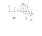
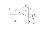
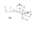
- a chamfer honing surface 11 is formed in the ridge line portion. The chamfer honing surface 11 is formed in a direction in which the chamfer honing surface 11 is parallel to the rake surface 7 in a cross section orthogonal to the corner blade 8 and the wiper blade 9 as shown in FIGS. 2, 3 and 5 to 10.
- the honing angle ⁇ to be made is constant.
- the honing width of the chamfer honing surface 11 that is, the width in the direction parallel to the rake surface 7 of the chamfer honing surface 11 in the cross section orthogonal to the corner blade 8 and the wiper blade 9 (opposite the rake surface 7).
- the width in the plan view as viewed from the insert center line L direction is formed so as to gradually increase as the wiper blade 9 moves away from the corner blade 8.
- the honing width W1 of the corner blade 8 shown in FIG. 2 is constant, and the honing widths W2 to W6 of the wiper blade 9 as shown in FIGS. 6 to 10 are the corner blade 8 and the wiper blade. 9 is formed so as to gradually increase from the contact point 9 to the opposite side of the corner blade 8.
- the honing width W2 to W6 of the wiper blade 9 gradually increases as the distance from the corner blade 8 increases.
- the honing angle ⁇ is constant, as shown in FIG. So that the ridge line E between the chamfer honing surface 11 and the flank 10 that is the cutting edge of the blade faces the polygonal surface 2 side opposite to the polygonal surface 2 on which the rake face 7 is formed as the distance from the corner blade 8 increases. Will be inclined.
- the honing angle ⁇ is constant and the honing widths W2 to W6 gradually increase as the honing width W2 to W6 moves away from the corner blade 8, so that the intersecting ridge line F between the chamfer honing surface 11 and the rake surface 7 is also shown in FIG.
- the angle ⁇ formed by the intersecting ridge line F away from the intersecting ridge line E with respect to the intersecting ridge line E in the plan view is set to 1 ° in the present embodiment.
- the intersecting ridge line E between the chamfer honing surface 11 and the flank 10 in the wiper blade 9 is a polygonal surface 2 opposite to the rake surface 7.
- the range inclined to the side is also 0. 0 with respect to the intersecting ridgeline E between the chamfer honing surface 11 and the flank 10 in the corner blade 8 in the direction perpendicular to the polygonal surface 2 on which the rake surface 7 is formed.
- the range is set to 0250 mm or less, and more preferably set to 0.0196 mm or less. For example, in this embodiment, the range is 0.0179 mm.
- a difference D1-D2 between the chamfer honing surface 11 and the depth D2 in the direction of the insert center line L from the rake face 7 to the intersecting ridge line E in the blade 8 is set to a range of 0.0250 mm or less.
- the honing angle ⁇ that is constant from the corner blade 8 to the wiper blade 9 is preferably in the range of 14 ° to 26 °, and is set to 25 ° in this embodiment.
- the maximum honing width W6 in the wiper blade 9 is desirably larger than the honing width W1 in the corner blade 8 in the range of 0.115 mm to 0.180 mm.
- the depth D2 of the corner blade 8 is preferably in the range of 0.0274 mm to 0.0732 mm, and the depth D1 of the wiper blade 9 is in the range of 0.0319 mm to 0.0878 mm from the depth D2. It is desirable to increase the size.
- the radius of curvature of the wiper blade 9 is larger than the radius of curvature of the corner blade 8 in the range of 9.5 mm to 10.5 mm.
- the length of the wiper blade 9 (the length of a straight line connecting the contact point with the corner blade 8 and the terminal end of the wiper blade 9 in the plan view) is preferably in the range of 0.33 mm to 0.40 mm. In this embodiment, it is 0.4 mm.
- the portion of the wiper blade 9 that is opposite to the corner blade 8 from the end of the wiper blade 9 is a main cutting edge 12 that is linear in the plan view, that is, a straight line with the wiper blade 9 that is convex in the plan view.
- the point of contact with the main cutting edge 12 forming a shape is the end of the wiper blade 9 opposite to the corner edge 8.
- the chamfer honing surface 11 of the main cutting edge 12 maintains the angle ⁇ formed by the intersecting ridge line F with the rake face 7 of the wiper blade 9 with respect to the intersecting ridge line E in the plan view. It extends to an obtuse corner of the polygonal surface 2.
- the intersecting ridge line E is also formed on the side of the polygonal surface 2 opposite to the polygonal surface 2 on which the rake face 7 is formed along the main cutting edge 12 and away from the corner edge 8 as shown in FIGS. It is inclined and is rounded up to the polygonal surface 2 on which the rake face 7 is formed at the obtuse corner.
- the cutting insert configured as described above is seated on an insert mounting seat formed on the holder of the blade-type replaceable cutting tool and can be attached and detached by a clamp pin, a lever, a clamp screw or the like inserted through the mounting hole 4. It is attached.
- the rake face 7 is directed so as to face the rotating direction of the rotating work material
- the corner blade 8 is directed in the feed direction with respect to the work material
- the corner blade 8 is opposite to the feed direction.
- the wiper blade 9 extending in the direction protrudes slightly in the cutting direction into the work material than the corner blade 8 and is given a negative side rake angle and a predetermined side clearance angle.
- the honing angle ⁇ of the chamfer honing surface 11 formed from the corner blade 8 to the wiper blade 9 is constant, and the honing width gradually increases as the wiper blade 9 moves away from the corner blade 8. ing.
- the intersection ridgeline E between the chamfer honing surface 11 and the flank 10 in the wiper blade 9 is inclined so as to be directed toward the polygonal surface 2 opposite to the rake surface 7 as it is away from the corner blade 8 as described above. Will do.
- the chamfer honing surface 11 and the wiper blade 9 can be formed by polishing the ISO standard cutting insert described above. That is, in the case of this embodiment, the insert body 1 is formed so as to be an ISO standard cutting insert in a state where the cutting edge tip 6 is joined to a base metal 5 such as a cemented carbide, and the insert body 1 described above.
- the side surface 3 on the corner portion C side is polished to form a flank 10 of the wiper blade 9 that bends toward the corner portion C side, and at the intersecting ridge line portion between the two side surfaces 3 on the corner portion C side.
- the present invention can be applied relatively easily.
- the cutting edge tip 6 is joined in this way, it is possible to prevent the boundary portion with the base metal 5 from being damaged.
- the entire insert body 1 is a cutting insert formed of a sintered material such as a cemented carbide, a dedicated mold is required to mold the green compact sintered on the insert body 1. In addition, the manufacturing cost of the cutting insert can be suppressed.
- the cross ridge line E between the chamfer honing surface 11 and the flank 10 in the wiper blade 9 is a rake face with respect to the cross ridge line E between the chamfer honing surface 11 and the flank 10 in the corner blade 8.
- it In the direction perpendicular to the polygonal surface 2 on which the surface 7 is formed, it is inclined toward the polygonal surface 2 side opposite to the rake face 7 within a range of 0.0250 mm or less as it is away from the corner blade 8.
- this range be a range of 0.0196 mm or less as described above.
- this intersecting ridge line E is in a range of 0.0070 mm or more with respect to the intersecting ridge line E between the chamfer honing surface 11 and the flank 10 in the corner blade 8 (the difference D1-D2 between the depths D1 and D2 is It is desirable to incline toward the polygonal surface 2 side opposite to the rake face 7 in a range of 0.0070 mm or more.
- the flank 10 of the wiper blade 9 that is curved on the side surface 3 of a general ISO standard cutting insert is formed, and the flank of the corner blade 8 is further in contact with the flank 10 of the wiper blade 9.
- the chamfer honing surface 11 is formed after forming the surface 10 at the intersecting ridge line portion between the two side surfaces 3, the tip of the corner blade 8 in the bisector direction of the corner portion C in the plan view is polished. It will be located inside the insert body 1 with respect to the case where processing is not performed.
- the flank 10 of the wiper blade 9 is in contact with the curved flank 10.
- the flat flank 10 is polished and formed toward the tip of the corner blade 8, and the flank 10 of the corner blade 8 is in contact with the flat flank 10, and the position of the tip is ISO standard.
- a rake surface 7 is formed between the corner blade 8 and the wiper blade 9. What is necessary is just to form the linear straight blade which touches the corner blade 8 and the wiper blade 9 in the opposing planar view.
- the corner blade 8 is moved in the bisector direction of the corner portion C without changing the radius of curvature of the corner blade 8 or the wiper blade 9.
- the projecting end can be set at the same position as the ISO standard cutting insert. For this reason, even if the program is not corrected by the cutting process in the NC lathe, it is possible to prevent uncut parts during the copying process.
- the honing width W1 of the corner blade 8 is constant, but the honing width gradually increases from the tip of the corner blade 8 located on the bisector of the corner portion C toward the wiper blade 9.
- the honing width may gradually increase from the middle of the corner blade 8 toward the wiper blade 9.
- the rake surface 7 is formed by the intersection ridge line E between the chamfer honing surface 11 and the flank 10 in the wiper blade 9.
- the depth D1 of the chamfer honing surface 11 in the direction of the insert center line L from the rake face 7 to the intersecting ridge line E at the end of the wiper blade 9 in the direction perpendicular to the formed polygonal surface 2, and the corner blade 8 An example is given and the effect is demonstrated about the difference D1-D2 with the depth D2 of the insert centerline L direction of the chamfer honing surface 11 from the rake face 7 to the intersection ridgeline E in FIG.
- the honing angle ⁇ is in the range of 14 ° to 26 °
- the maximum honing width W6 in the wiper blade 9 is in the range of 0.115 mm to 0.180 mm
- the ridge line 7 from the rake face 7 at the end of the wiper blade 9 is intersected.
- the insert center line L depth D1 of the chamfer honing surface 11 to E is in the range of 0.0319 mm to 0.0878 mm, and the insert center of the chamfer honing surface 11 from the rake face 7 to the intersecting ridge line E in the corner blade 8
- Tables 1 and 6 show the depths D1 and D2 and the difference D1 ⁇ D2 and the honing width W6 as Examples 1 to 6.
- the depth D1 and the depth D2 are equal and the difference D1-D2 is 0, that is, the intersection of the chamfer honing surface 11 and the flank 10 in the wiper blade 9
- the ridge line E moves away from the corner blade 8
- it is not inclined so as to be directed to the polygonal surface 2 side opposite to the rake face 7, and is inclined, but the inclination is small and the difference D1-D2 is 0.0070 mm.
- the cutting inserts of Examples 1 to 6 and Comparative Examples 1 to 4 are basically the CNGA120408 type in ISO 13399 (JIS-B4120-1998) except for the periphery of the corner portion C. Further, the honing angle ⁇ is calculated from the honing width W6 and the depth D1, but in Examples 1 to 6, they are 14 °, 15 °, 15 °, 25 °, 26 °, and 26 ° in this order, and Comparative Examples 1 to At 4, the angles are 25 °, 15 °, 25 °, and 35 ° in this order. Furthermore, a cBN sintered body was used as the cutting edge tip 6.
- the outer diameter continuous turning was performed on a cylindrical work material having a diameter of 30 mm and a length of 100 mm made of SCr420 (hardness 60HRc), and the cutting speed
- the cutting insert life was determined under the conditions of Vc: 160 m / min, feed amount per rotation of the work material fr: 0.2 mm / rev, and cutting amount ap: 0.15 mm.
- the cutting length (km) when the surface roughness Rz of the work material (maximum height roughness in JIS-B0601-2001) is 6.3 ⁇ m or more is defined as the life. Table 1 also shows the cutting length at the time when this life is reached.
- the cutting inserts of Examples 1 to 6 do not generate chatter vibrations, and all can obtain a cutting length of 10 km or more, and are highly accurate and stable. It was possible to carry out the cutting process for a long time. Particularly, in Examples 1 to 4 and Example 6 in which the difference D1-D2 is in the range of 0.0196 mm or less, a cutting length exceeding 10 km is obtained until the lifetime. From this result, it can be seen that the difference D1-D2 is preferably in the range of 0.0196 mm or less, more preferably in the range of 0.0196 mm or less, and further preferably in the range of 0.0070 mm or more. .
- the present invention relates to a cutting insert that is attached to a cutting edge replaceable bite or the like and performs turning of a work material.
- the corner portion of the polygonal surface of the polygonal plate-like insert body has a rake face on the polygonal face and has a convex curve shape in plan view facing the rake face.
- a corner blade is formed, and a wiper blade having a convex curve shape with a radius of curvature larger than that of the corner blade is formed on a side ridge portion of the polygonal surface connected to the corner blade in a plan view facing the rake face.
- a chamfer honing surface is formed from the corner blade to the wiper blade.
- the chamfer honing surface has a constant honing angle and a honing width in a plan view facing the rake surface. Since the blade gradually increases as it moves away from the corner blade, it can be manufactured at low cost without the need for a dedicated mold, and cBN sintering It can also be applied to cutting inserts equipped with diamond sintered bodies, and by suppressing the wiper blade from rubbing against the work material and suppressing the increase in cutting resistance, it can be used for inner diameter machining and small diameter machining by high feed. It is possible to perform stable cutting with high accuracy by preventing chatter vibration and waviness of the machined surface even when machining the outer diameter of the material.
Landscapes
- Engineering & Computer Science (AREA)
- Mechanical Engineering (AREA)
- Cutting Tools, Boring Holders, And Turrets (AREA)
Abstract
本発明の切削インサートは、多角形板状のインサート本体の多角形面のコーナ部に、多角形面にすくい面を有してすくい面に対向する平面視に凸曲線状をなすコーナ刃が形成されるとともに、コーナ刃に連なる多角形面の辺稜部にはすくい面に対向する平面視にコーナ刃よりも曲率半径の大きな凸曲線状をなすワイパー刃が形成され、コーナ刃からワイパー刃にかけてはチャンファーホーニング面が形成されていて、チャンファーホーニング面は、ホーニング角が一定で、すくい面に対向する平面視におけるホーニング幅がワイパー刃においてコーナ刃から離れるに従い漸次大きくなる。
Description
本発明は、刃先交換式のバイトなどに取り付けられて被削材の旋削加工を行う切削インサートに関するものである。本願は、2016年6月28日に出願された特願2016-127690について優先権を主張し、その内容をここに援用する。
このような切削インサートとして、例えば特許文献1には、機械工作面の滑度の向上を目的として、ノーズ切刃が少なくとも5つの円セグメントに分割された切削インサートが提案されている。ここで、この特許文献1に記載された切削インサートでは、ノーズ半径の二等分線が第1曲率半径reを有する第1セグメントに交差し、第1セグメントの両側には第2曲率半径r2を有する第2セグメントが接合し、さらに第2セグメントには第3曲率半径r3を有する第3セグメントが接合していて、第1~第3曲率半径re、r2、r3はr3>re>r2の関係を有している。
また、特許文献2にも、面粗さが良好な仕上げ面を得ることなどを目的として、先行して被削材に切り込ませる仕上げ刃(コーナ刃)と、この仕上げ刃に続いて被削材を仕上げ加工する超仕上げ刃を有し、超仕上げ刃が、仕上げ刃の位置から切り込み量を増加させる方向に所定量突出しており、工具送り方向に延びるバニシング部と仕上げ刃からバニシング部に至るさらえ部を備えており、この超仕上げ刃が仕上げ刃によって加工された面の加工変質層を除去しながら仕上げ面のバニシングを行うように構成された切削インサートが提案されている。
さらに、特許文献3にも、被削材の仕上げ面粗度の向上を目的として、すくい面としての上面と着座面としての下面と逃げ面としての側面を備えた多角形板状体からなり、上記すくい面と逃げ面との間の稜辺に切刃が形成され、上記多角形板状体の稜辺が交差するコーナー部分にはコーナー切刃と該コーナー切刃の両端側に連なるサラエ刃と該サラエ刃に連なる横切刃とを備え、上記サラエ刃に上記すくい面側へ突出する円弧状の突出部が形成されたことを特徴とする切削インサートが提案されている。
しかしながら、特許文献1に記載された切削インサートでは、上述した少なくとも5つの円セグメントに分割されたノーズ切刃が、該特許文献1の図1に示されるように1つの平面上に配置されている。このため、例えば高送り加工したときに、特にコーナ刃(第1セグメント)から離れた第3セグメントのワイパー刃が被削材に擦れて切削抵抗の増大を招き、切削が不安定となって内径加工や小径の被削材の外径加工などにおいてビビリ振動や加工面のうねりを生じるおそれがある。このような問題は、超仕上げ刃(ワイパー刃)が仕上げ面のバニシング、すなわち擦りつけを行うように構成された特許文献2に記載の切削インサートでは、一層顕著なものとなる。
一方、特許文献3に記載された切削インサートのように、サラエ刃(ワイパー刃)にすくい面側へ突出する円弧状の突出部を形成した切削インサートを超硬合金のような焼結材料によって一体焼結して製造する場合、一般的なISO規格の切削インサートを研磨加工して突出部を形成するのは困難である。このため、切削インサートに焼結される前の圧粉体をプレス成形する金型に、突出部に対応した凹部を形成しなければならず、専用の金型が必要となってコスト増を招くことになる。さらに、例えばコーナ刃からワイパー刃にかけての部分にcBN焼結体やダイヤモンド焼結体を配設した切削インサートには、このような突出部を形成すること自体できない。
本発明は、このような背景の下になされたもので、ワイパー刃を備えた切削インサートにおいて、コスト増を防ぐことができるとともにcBN焼結体やダイヤモンド焼結体を配設した切削インサートにも適用可能でありながら、高送り加工でも被削材への擦りつけによる切削抵抗の増大を防止して、内径加工や小径被削材の外径加工において安定した切削を行うことが可能な切削インサートを提供することを目的としている。
上記課題を解決して、このような目的を達成するために、本発明の一態様である切削インサートは、多角形板状のインサート本体の多角形面のコーナ部に、上記多角形面にすくい面を有して該すくい面に対向する平面視に凸曲線状をなすコーナ刃が形成されるとともに、このコーナ刃に連なる上記多角形面の辺稜部には上記すくい面に対向する平面視に上記コーナ刃よりも曲率半径の大きな凸曲線状をなすワイパー刃が形成されており、上記コーナ刃から上記ワイパー刃にかけてはチャンファーホーニング面が形成されていて、このチャンファーホーニング面は、ホーニング角が一定で、上記すくい面に対向する平面視におけるホーニング幅が上記ワイパー刃において上記コーナ刃から離れるに従い漸次大きくなることを特徴とする。
このように構成された切削インサートでは、コーナ刃からワイパー刃にかけて形成されたチャンファーホーニング面が、ホーニング角は一定であるものの、すくい面に対向する平面視におけるホーニング幅がワイパー刃においてコーナ刃から離れるに従い漸次大きくなっているので、ワイパー刃におけるチャンファーホーニング面と上記多角形面の周りに配置される側面に形成される逃げ面との交差稜線は、コーナ刃から離れるに従いすくい面とは反対の多角形面側に向かうように傾斜することになる。
このため、切削加工の際にワイパー刃に負の横すくい角と所定の横逃げ角を与えると、凸曲線状のワイパー刃の刃先であるチャンファーホーニング面と逃げ面との上記交差稜線は、コーナ刃側よりもコーナ刃とは反対側で、より大きく加工面に対して逃げるように離れることになる。従って、このコーナ刃とは反対側のワイパー刃やその逃げ面が被削材に強く擦りつけられて切削抵抗が増大するのを防ぐことができ、高送り加工でもビビリ振動や加工面のうねりを防止して安定した切削加工を行うことが可能となる。
さらに、このようなチャンファーホーニング面やワイパー刃は、一般的なISO規格の切削インサートに研磨加工を施すことによって形成することができる。このため、インサート本体が超硬合金のような焼結材料によって一体形成されていても専用の金型を必要とすることが無く、切削インサートの製造コストを抑制することができる。また、コーナ刃からワイパー刃にかけての部分にcBN焼結体やダイヤモンド焼結体を配設した切削インサートであっても適用が可能である。
ここで、上述のように上記多角形面の周りに配置される上記インサート本体の側面には逃げ面が形成されるが、上記コーナ刃における上記チャンファーホーニング面と上記逃げ面との交差稜線に対して、上記ワイパー刃における上記チャンファーホーニング面と上記逃げ面との交差稜線は、上記すくい面が形成された多角形面に垂直な方向において、上記コーナ刃から離れるに従い0.0250mm以下の範囲で上記すくい面とは反対の多角形面側に向かうように傾斜しているのが望ましい。
すなわち、このワイパー刃におけるチャンファーホーニング面と逃げ面との交差稜線の傾斜が上記範囲よりも大きいと、コーナ刃とは反対側においてワイパー刃の刃先が加工面から離れすぎてしまい、ワイパー刃として加工面を十分平滑に仕上げ加工することができなくなるおそれがある。なお、この範囲は、0.0196mm以下の範囲であることが、より望ましい。
ただし、この傾斜が小さすぎて、ワイパー刃におけるチャンファーホーニング面と逃げ面との交差稜線がすくい面とされた多角形面に平行に近いと、上述したような効果を得ることができなくなるおそれがある。このため、この交差稜線はコーナ刃におけるチャンファーホーニング面と逃げ面との交差稜線に対して0.0070mm以上の範囲ですくい面とは反対の多角形面側に向かうように傾斜しているのが望ましい。
なお、上述のような一般的なISO規格の切削インサートにおける直線状の主切刃に接するように研磨加工によって凸曲線状のワイパー刃を形成し、さらにこのワイパー刃に接するようにコーナ部に凸円弧等の凸曲線状のコーナ刃を形成する場合には、このコーナ部の二等分線上におけるコーナ刃の突端が研磨加工前よりもインサート本体の内側に後退してしまう。従って、そのような切削インサートを用いて、例えばNC旋盤により被削材に倣い加工を行おうとすると、コーナ刃の突端が後退した分だけ削り残しが発生してしまうため、NC旋盤のプログラムを修正しなければならない。
そこで、このような場合には、上記コーナ刃と上記ワイパー刃との間に、上記すくい面に対向する平面視に上記コーナ刃と上記ワイパー刃に接する直線状の直線刃を形成すればよい。コーナ刃とワイパー刃との間に直線刃が介在することにより、コーナ刃やワイパー刃の曲率半径を変えずにコーナ刃の突端をISO規格の切削インサートと同じ位置とすることができ、NC旋盤における切削加工でプログラムを修正しなくても、倣い加工の際の削り残しを防止することができる。
以上説明したように、本発明によれば、専用の金型を必要とすることが無く低コストで製造可能であるとともに、cBN焼結体やダイヤモンド焼結体を配設した切削インサートにも適用可能であり、ワイパー刃が被削材に擦られるのを抑えて切削抵抗の増大を抑制することにより、高送りによる内径加工や小径被削材の外径加工でもビビリ振動や加工面のうねりを防いで高精度で安定した切削加工を行うことが可能となる。
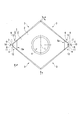
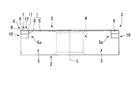
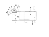
図1ないし図10は、本発明の一実施形態を示すものである。本実施形態において、インサート本体1は、多角形板状、具体的には鋭角のコーナ部の角度が80°の菱形平板状に形成されており、2つの多角形面(菱形面)2と、これらの多角形面2の周りに配置される4つの長方形状の側面3とを備えている。2つの多角形面2の中央には、これらの多角形面2の中心を通るインサート中心線Lを中心とする断面円形をなしてインサート本体1を貫通する取付孔4が開口しており、2つの多角形面2は上記インサート中心線Lに垂直な平面状とされている。
ここで、本実施形態のインサート本体1は、超硬合金等の硬質材料により上述のような略多角形板状に形成された台金5の2つの多角形面2のうち1つの多角形面(図2および図3における上側の多角形面)2の2つの鋭角のコーナ部Cに断面L字状の切欠部5aが形成され、この切欠部5aに、台金5よりも高硬度のcBN焼結体やダイヤモンド焼結体よりなる三角形板状の切刃チップ6がロウ付け等によって接合されることにより、図1ないし図3に示すような多角形板状(菱形平板状)に形成されている。
さらに、本実施形態では、こうして切刃チップ6が接合された1つの多角形面2の2つのコーナ部Cに、この多角形面2の切刃チップ6上に多角形面2と面一なすくい面7を有し、該すくい面7に対向して上記インサート中心線L方向から見た平面視において図4に示すような凸円弧等の凸曲線状をなすコーナ刃8が形成されている。従って、このすくい面7もインサート中心線Lに垂直な平面状とされる。なお、本実施形態のインサート本体1は、コーナ部Cの周辺を除いて、基本的にISO13399(JIS-B4120-1998)に準拠している。
また、このコーナ部Cに連なる上記1つの多角形面2の2つの辺稜部には、本実施形態ではコーナ刃8に直接接するように、同じく該1つの多角形面2にすくい面7を有して、該すくい面7に対向して上記インサート中心線L方向から見た平面視においてコーナ刃8よりも大きな曲率半径の凸円弧等の凸曲線状をなすワイパー刃9が形成されている。従って、多角形面2の周りに配置される4つの側面3のうち上記コーナ部Cに連なる交差稜線部に交差する2つの側面3には、少なくとも上記すくい面7側に、コーナ刃8およびワイパー刃9に連なる逃げ面10が形成されることになる。
なお、本実施形態の切削インサートは、基本的にはこの逃げ面10がすくい面7に直交する方向に延びるネガティブタイプの切削インサートであり、コーナ刃8の逃げ面10やワイパー刃9の終端よりもコーナ刃8と反対側では、このように逃げ面10がすくい面7に直交する方向に延びている。
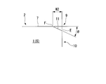
そして、このコーナ部Cに形成されたコーナ刃8からその両側のワイパー刃9にかけてはチャンファーホーニングが施されていて、これらコーナ刃8とワイパー刃9のすくい面7と逃げ面10との交差稜線部に、チャンファーホーニング面11が形成されている。このチャンファーホーニング面11は、図2、図3および図5ないし図10に示すようにコーナ刃8およびワイパー刃9に直交する断面において該チャンファーホーニング面11がすくい面7に平行な方向に対してなすホーニング角θが一定とされている。
これに対して、このチャンファーホーニング面11のホーニング幅、すなわち同じくコーナ刃8およびワイパー刃9に直交する断面におけるチャンファーホーニング面11のすくい面7に平行な方向の幅(すくい面7に対向してインサート中心線L方向から見た平面視における幅)は、ワイパー刃9においてコーナ刃8から離れるに従い漸次大きくなるように形成されている。ここで、本実施形態では、図2に示すコーナ刃8におけるホーニング幅W1は一定とされ、図6ないし図10に示すようにワイパー刃9におけるホーニング幅W2~W6が、コーナ刃8とワイパー刃9との接点からコーナ刃8とは反対側に離れるに従い漸次大きくなるように形成されている。
このようにワイパー刃9のホーニング幅W2~W6がコーナ刃8から離れるに従い漸次大きくなることにより、ホーニング角θが一定とされた上記構成の切削インサートにおいては、図2に示すようにワイパー刃9の刃先となるチャンファーホーニング面11と逃げ面10との交差稜線Eが、コーナ刃8から離れるに従いすくい面7が形成された多角形面2とは反対の多角形面2側に向かうように傾斜することになる。
また、同様にホーニング角θが一定でホーニング幅W2~W6がコーナ刃8から離れるに従い漸次大きくなることにより、チャンファーホーニング面11とすくい面7との交差稜線Fも、上記平面視において図1や図4に示すようにコーナ刃8から離れるに従い上記交差稜線Eから離れて多角形面2の内側に向かうように傾斜することになる。なお、こうして交差稜線Eから離れる交差稜線Fが上記平面視に交差稜線Eに対してなす角度αは、本実施形態では1°とされている。
ただし、ワイパー刃9におけるホーニング幅の増大量は僅かであり、これに伴いワイパー刃9におけるチャンファーホーニング面11と逃げ面10との上記交差稜線Eがすくい面7とは反対の多角形面2側に向かうように傾斜する範囲も、すくい面7が形成された多角形面2に垂直な方向において、コーナ刃8におけるチャンファーホーニング面11と逃げ面10との交差稜線Eに対し、0.0250mm以下の範囲とされていて、0.0196mm以下の範囲とされるのがより望ましく、例えば本実施形態では0.0179mmとされている。
すなわち、図10に示すコーナ刃8から最も離れたワイパー刃9の終端におけるすくい面7から交差稜線Eまでのチャンファーホーニング面11のインサート中心線L方向の深さD1と、図5に示すコーナ刃8におけるすくい面7から交差稜線Eまでのチャンファーホーニング面11のインサート中心線L方向の深さD2との差D1-D2が0.0250mm以下の範囲とされている。
なお、コーナ刃8からワイパー刃9にかけて一定とされるホーニング角θは14°~26°の範囲とされるのが望ましく、本実施形態では25°とされている。さらに、ワイパー刃9において最大となるホーニング幅W6は0.115mm~0.180mmの範囲でコーナ刃8におけるホーニング幅W1よりも大きくされるのが望ましい。従って、コーナ刃8における上記深さD2は0.0274mm~0.0732mmの範囲とされるのが望ましく、ワイパー刃9における上記深さD1は0.0319mm~0.0878mmの範囲で深さD2よりも大きくされるのが望ましい。
さらにまた、やはりインサート本体1の大きさにもよるが、ワイパー刃9の上記曲率半径は9.5mm~10.5mmの範囲でコーナ刃8の曲率半径よりも大きくされるのが望ましい。また、ワイパー刃9の長さ(上記平面視においてコーナ刃8との接点とワイパー刃9の終端とを結んだ直線の長さ)は0.33mm~0.40mmの範囲とされるのが望ましく、本実施形態では0.4mmとされている。
なお、ワイパー刃9の終端からコーナ刃8と反対側の部分は、上記平面視において直線状をなす主切刃12とされており、すなわち上記平面視において凸曲線状をなすワイパー刃9と直線状をなす主切刃12のとの接点がワイパー刃9のコーナ刃8とは反対側の終端となる。この主切刃12のチャンファーホーニング面11は、図1に示すように上記平面視において、ワイパー刃9におけるすくい面7との交差稜線Fが上記交差稜線Eに対してなす角度αのまま、多角形面2の鈍角のコーナ部に延びている。従って、交差稜線Eも、図2および図3に示すように主切刃12に沿ってコーナ刃8から離れるに従いすくい面7が形成された多角形面2とは反対の多角形面2側に傾斜しており、上記鈍角のコーナ部ですくい面7が形成された多角形面2に切れ上がっている。
このように構成された切削インサートは、刃先交換式バイトのホルダに形成されたインサート取付座に着座させられて、上記取付孔4に挿通されたクランプピン、レバー、あるいはクランプネジ等により着脱可能に取り付けられる。そして、回転する被削材の回転方向に対向するように上記すくい面7が向けられるとともに、コーナ刃8が被削材に対する送り方向に向けられ、さらにこのコーナ刃8から送り方向とは反対側に延びるワイパー刃9は、コーナ刃8よりも極僅かに被削材への切り込み方向に突出させられて負の横すくい角と所定の横逃げ角が与えられる。
ここで、上記構成の切削インサートでは、コーナ刃8からワイパー刃9にかけて形成されたチャンファーホーニング面11のホーニング角θは一定で、ホーニング幅がワイパー刃9においてコーナ刃8から離れるに従い漸次大きくなっている。このため、ワイパー刃9におけるチャンファーホーニング面11と逃げ面10との交差稜線Eは、上述のようにコーナ刃8から離れるに従いすくい面7とは反対の多角形面2側に向かうように傾斜することになる。
従って、被削材への切り込み方向に突出させられたワイパー刃9に上述のような負の横すくい角と所定の横逃げ角を与えると、凸曲線状のワイパー刃9の刃先となるチャンファーホーニング面11と逃げ面10との交差稜線Eは、コーナ刃8とは反対側でコーナ刃8側よりも大きく加工面から離れて逃げが与えられることになる。このため、ワイパー刃9やその逃げ面10が被削材に擦りつけられるのを抑制して切削抵抗の増大を防ぐことができ、高送り加工においてもビビリ振動や加工面のうねりが生じるのを防止して高精度で安定した切削加工を行うことが可能となる。
また、上記チャンファーホーニング面11やワイパー刃9は、上述したISO規格の切削インサートに研磨加工を施すことによって形成することができる。すなわち、本実施形態の場合には、超硬合金等の台金5に切刃チップ6を接合した状態でISO規格の切削インサートとなるようにインサート本体1を形成し、このインサート本体1の上記コーナ部C側の側面3に研磨加工を施してコーナ部C側に向かうに従い凸曲するワイパー刃9の逃げ面10を形成するとともに、コーナ部C側の2つの側面3同士の交差稜線部にはワイパー刃9の逃げ面10に接するコーナ刃8の逃げ面10を形成した上で、側面3および逃げ面10とすくい面7を有する多角形面2の交差稜線部にチャンファーホーニング面11を形成すればよい。
従って、本実施形態のように台金5よりも硬質なcBN焼結体やダイヤモンド焼結体よりなる切刃チップ6がコーナ部Cのコーナ刃8からワイパー刃9にかけて配設された切削インサートでも、比較的容易に本発明を適用することが可能となる。しかも、こうして切刃チップ6を接合した場合に、台金5との境界部に損傷が生じるのも防ぐことができる。また、たとえインサート本体1の全体が超硬合金のような焼結材料によって形成された切削インサートでも、インサート本体1に焼結される圧粉体を成型するために専用の金型を必要とすることも無く、切削インサートの製造コストを抑制することができる。
さらに、本実施形態では、ワイパー刃9におけるチャンファーホーニング面11と逃げ面10との交差稜線Eが、コーナ刃8におけるチャンファーホーニング面11と逃げ面10との交差稜線Eに対し、すくい面7が形成された多角形面2に垂直な方向において、コーナ刃8から離れるに従い0.0250mm以下の範囲ですくい面7とは反対の多角形面2側に向かうように傾斜しており、上述のように被削材の加工面をワイパー刃9によって確実かつ十分平滑に仕上げ加工することが可能となる。
すなわち、この範囲を超えてワイパー刃9におけるチャンファーホーニング面11と逃げ面10との交差稜線Eがすくい面7とは反対の多角形面2側まで延びていると、ワイパー刃9の刃先となるこの交差稜線Eが被削材から離れすぎてしまい、ワイパー刃9によって加工面を十分平滑に仕上げることができなくなるおそれがある。なお、この範囲は、上述のように0.0196mm以下の範囲とされるのが、より望ましい。
ただし、ワイパー刃9におけるチャンファーホーニング面11と逃げ面10との交差稜線Eが、すくい面7が形成された多角形面2と平行に近いと、上述したような効果を得ることができなくなるおそれがあるので、この交差稜線Eはコーナ刃8におけるチャンファーホーニング面11と逃げ面10との交差稜線Eに対して0.0070mm以上の範囲(上記深さD1、D2の差D1-D2が0.0070mm以上の範囲)ですくい面7とは反対の多角形面2側に向かうように傾斜しているのが望ましい。
ところで、上述のように一般的なISO規格の切削インサートの側面3に凸曲したワイパー刃9の逃げ面10を形成し、さらにこのワイパー刃9の逃げ面10に接するようにコーナ刃8の逃げ面10を2つの側面3同士の交差稜線部に形成した上で、チャンファーホーニング面11を形成した場合、上記平面視におけるコーナ部Cの二等分線方向のコーナ刃8の突端は、研磨加工を行わない場合に対してインサート本体1の内側に位置することになる。このため、そのような切削インサートにより、例えばNC旋盤を用いた倣い加工を行おうとすると、コーナ刃8の突端が後退した分だけ削り残しが発生してしまうため、NC旋盤のプログラムを修正しなければならないのは上述した通りである。
そこで、このような場合には、コーナ部Cに交差する2つの側面3にワイパー刃9の逃げ面10を凸曲するように研磨加工によって形成した後に、この凸曲した逃げ面10に接するようにコーナ刃8の突端に向けて平面状の逃げ面10を研磨加工して形成し、さらにこれら平面状の逃げ面10に接するようにコーナ刃8の逃げ面10を、突端の位置がISO規格の切削インサートのコーナ刃の逃げ面と同じとなるように研磨加工によって形成してから、チャンファーホーニング面11を形成することにより、コーナ刃8とワイパー刃9との間に、すくい面7に対向する平面視にコーナ刃8とワイパー刃9に接する直線状の直線刃を形成すればよい。
このようにコーナ刃8とワイパー刃9との間に直線刃を形成することにより、コーナ刃8やワイパー刃9の曲率半径を変えずにコーナ刃8をコーナ部Cの二等分線方向にインサート本体1の外側に突出させて、その突端をISO規格の切削インサートと同じ位置とすることができる。このため、NC旋盤における切削加工でプログラムを修正しなくても、倣い加工の際の削り残しを防止することができる。
なお、本実施形態では、コーナ刃8におけるホーニング幅W1は一定であるが、コーナ部Cの二等分線上に位置するコーナ刃8の突端からワイパー刃9に向かうに従いホーニング幅が漸次大きくなっていたり、コーナ刃8の途中からワイパー刃9に向かうに従いホーニング幅が漸次大きくなっていたりしてもよい。
次に、コーナ刃8おけるチャンファーホーニング面11と逃げ面10との交差稜線Eに対して、ワイパー刃9におけるチャンファーホーニング面11と逃げ面10との交差稜線Eが、すくい面7が形成された多角形面2に垂直な方向においてなす範囲、すなわちワイパー刃9の終端におけるすくい面7から交差稜線Eまでのチャンファーホーニング面11のインサート中心線L方向の深さD1と、コーナ刃8におけるすくい面7から交差稜線Eまでのチャンファーホーニング面11のインサート中心線L方向の深さD2との差D1-D2について、実施例を挙げて、その効果について実証する。
本実施例では、ホーニング角θが14°~26°の範囲、ワイパー刃9において最大となるホーニング幅W6が0.115mm~0.180mmの範囲、ワイパー刃9の終端におけるすくい面7から交差稜線Eまでのチャンファーホーニング面11のインサート中心線L方向の深さD1が0.0319mm~0.0878mmの範囲、コーナ刃8におけるすくい面7から交差稜線Eまでのチャンファーホーニング面11のインサート中心線L方向の深さD2が0.0274mm~0.0732mmの範囲で、これらの深さD1とD2との差D1-D2が0.0070mm~0.0250mmとされた6種の切削インサートを製造した。これらを実施例1~6として、深さD1、D2、およびその差D1-D2とホーニング幅W6とを表1に示す。
また、これら実施例1~6に対する比較例として、深さD1と深さD2とが等しくて差D1-D2が0であり、すなわちワイパー刃9におけるチャンファーホーニング面11と逃げ面10との交差稜線Eがコーナ刃8から離れるに従いすくい面7とは反対の多角形面2側に向かうように傾斜していないものと、傾斜はしているものの傾斜が小さくて差D1-D2が0.0070mm未満のもの、逆に傾斜が大きくて差D1-D2が0.0250mmを上回るもの、および深さD1が0.0878mmよりも大きいとともに深さD2も0.0732mmより大きくて差D1-D2も0.0250mmを上回るものの4種の切削インサートも製造した。これらを順に比較例1~4として、同じく深さD1、D2、およびその差D1-D2とホーニング幅W6とを表1に併せて示す。
なお、これら実施例1~6および比較例1~4の切削インサートは、コーナ部Cの周辺を除いて、基本的にISO13399(JIS-B4120-1998)におけるCNGA120408タイプのものである。また、ホーニング角θはホーニング幅W6と深さD1から算出されるが、実施例1~6では順に14°、15°、15°、25°、26°、26°であり、比較例1~4では順に25°、15°、25°、35°である。さらに、切刃チップ6としてはcBN焼結体を用いた。
そして、これら実施例1~6および比較例1~4の切削インサートにより、SCr420(硬さ60HRc)よりなる直径30mm、長さ100mmの円柱状の被削材に外径連続旋削加工を、切削速度Vc:160m/min、被削材1回転当たりの送り量fr:0.2mm/rev、切り込み量ap:0.15mmの条件で乾式加工で行い、切削インサートの寿命について判定した。なお、判定は、被削材の表面粗さRz(JIS-B0601-2001における最大高さ粗さ)が6.3μm以上になった時点での切削長(km)を寿命とした。この寿命となった時点での切削長も表1に併せて示す。

この表1の結果より、まずワイパー刃9におけるチャンファーホーニング面11と逃げ面10との交差稜線Eがコーナ刃8から離れるに従いすくい面7とは反対の多角形面2側に向かうように傾斜していない比較例1と、傾斜はしているものの傾斜が小さくて差D1-D2が0.0070mm未満の比較例2では、ビビリ振動が発生して10kmに満たない切削長で寿命と判定された。また、逆に傾斜が大きい比較例3では、ワイパー刃9による加工面の平滑化効果(ワイパー効果)が少なく、やはり短い切削長で被削材の表面粗さRzが大きくなってしまった。さらに、深さD1、D2、およびその差D1-D2が上記範囲よりも大きくてホーニング角θも26°を上回る比較例4でもビビリ振動が発生してしまい、最も短い切削長で寿命となった。
これら比較例1~4の切削インサートに対して、実施例1~6の切削インサートでは、ビビリ振動等が発生することはなく、いずれも10km以上の切削長を得ることができ、高精度で安定した切削加工を長期に亙って行うことが可能であった。特に、差D1-D2が0.0196mm以下の範囲の実施例1~4および実施例6では寿命まで10kmを上回る切削長が得られている。この結果より、差D1-D2は0.0196mm以下の範囲であるのが望ましく、0.0196mm以下の範囲であることがより望ましく、また0.0070mm以上の範囲であることがさらに望ましいことが分かる。
以上、本発明の好ましい実施形態について説明したが、本発明は条規の実施形態に限定されることはない。本発明の趣旨を逸脱しない範囲で、構成の付加、省略、置換、およびその他の変更が可能である。本発明は、上述した説明によって限定されることはなく、添付の特許請求の範囲よってのみ限定される。
本発明は、刃先交換式のバイトなどに取り付けられて被削材の旋削加工を行う切削インサートに関するものである。本発明の切削インサートによれば、多角形板状のインサート本体の多角形面のコーナ部に、上記多角形面にすくい面を有して該すくい面に対向する平面視に凸曲線状をなすコーナ刃が形成されるとともに、このコーナ刃に連なる上記多角形面の辺稜部には上記すくい面に対向する平面視に上記コーナ刃よりも曲率半径の大きな凸曲線状をなすワイパー刃が形成されており、上記コーナ刃から上記ワイパー刃にかけてはチャンファーホーニング面が形成されていて、このチャンファーホーニング面は、ホーニング角が一定で、上記すくい面に対向する平面視におけるホーニング幅が上記ワイパー刃において上記コーナ刃から離れるに従い漸次大きくなるので、専用の金型を必要とすることが無く低コストで製造可能であるとともに、cBN焼結体やダイヤモンド焼結体を配設した切削インサートにも適用可能であり、ワイパー刃が被削材に擦られるのを抑えて切削抵抗の増大を抑制することにより、高送りによる内径加工や小径被削材の外径加工でもビビリ振動や加工面のうねりを防いで高精度で安定した切削加工を行うことが可能となる。
1 インサート本体
2 多角形面
3 側面
7 すくい面
8 コーナ刃
9 ワイパー刃
10 逃げ面
11 チャンファーホーニング面
L インサート中心線
C コーナ部
E チャンファーホーニング面11と逃げ面10との交差稜線
F チャンファーホーニング面11とすくい面7との交差稜線
D1 ワイパー刃9の終端におけるすくい面7から交差稜線Eまでのチャンファーホーニング面11のインサート中心線L方向の深さ
D2 コーナ刃8におけるすくい面7から交差稜線Eまでのチャンファーホーニング面11のインサート中心線L方向の深さ
W1~W6 ホーニング幅
θ ホーニング角
2 多角形面
3 側面
7 すくい面
8 コーナ刃
9 ワイパー刃
10 逃げ面
11 チャンファーホーニング面
L インサート中心線
C コーナ部
E チャンファーホーニング面11と逃げ面10との交差稜線
F チャンファーホーニング面11とすくい面7との交差稜線
D1 ワイパー刃9の終端におけるすくい面7から交差稜線Eまでのチャンファーホーニング面11のインサート中心線L方向の深さ
D2 コーナ刃8におけるすくい面7から交差稜線Eまでのチャンファーホーニング面11のインサート中心線L方向の深さ
W1~W6 ホーニング幅
θ ホーニング角
Claims (5)
- 多角形板状のインサート本体の多角形面のコーナ部に、上記多角形面にすくい面を有して該すくい面に対向する平面視に凸曲線状をなすコーナ刃が形成されるとともに、このコーナ刃に連なる上記多角形面の辺稜部には上記すくい面に対向する平面視に上記コーナ刃よりも曲率半径の大きな凸曲線状をなすワイパー刃が形成されており、上記コーナ刃から上記ワイパー刃にかけてはチャンファーホーニング面が形成されていて、このチャンファーホーニング面は、ホーニング角が一定で、上記すくい面に対向する平面視におけるホーニング幅が上記ワイパー刃において上記コーナ刃から離れるに従い漸次大きくなることを特徴とする切削インサート。
- 上記多角形面の周りに配置される上記インサート本体の側面には逃げ面が形成され、上記コーナ刃における上記チャンファーホーニング面と上記逃げ面との交差稜線に対して、上記ワイパー刃における上記チャンファーホーニング面と上記逃げ面との交差稜線が、上記すくい面が形成された多角形面に垂直な方向において、上記コーナ刃から離れるに従い0.0250mm以下の範囲で上記すくい面とは反対の多角形面側に向かうように傾斜していることを特徴とする請求項1に記載の切削インサート。
- 上記多角形面の周りに配置される上記インサート本体の側面には逃げ面が形成され、上記コーナ刃における上記チャンファーホーニング面と上記逃げ面との交差稜線に対して、上記ワイパー刃における上記チャンファーホーニング面と上記逃げ面との交差稜線が、上記すくい面が形成された多角形面に垂直な方向において、上記コーナ刃から離れるに従い0.0196mm以下の範囲で上記すくい面とは反対の多角形面側に向かうように傾斜していることを特徴とする請求項1に記載の切削インサート。
- 上記多角形面の周りに配置される上記インサート本体の側面には逃げ面が形成され、上記コーナ刃における上記チャンファーホーニング面と上記逃げ面との交差稜線に対して、上記ワイパー刃における上記チャンファーホーニング面と上記逃げ面との交差稜線が、上記すくい面が形成された多角形面に垂直な方向において、上記コーナ刃から離れるに従い0.0070mm以上の範囲で上記すくい面とは反対の多角形面側に向かうように傾斜していることを特徴とする請求項1から請求項3のうちいずれか一項に記載の切削インサート。
- 上記コーナ刃と上記ワイパー刃との間には、上記すくい面に対向する平面視に上記コーナ刃と上記ワイパー刃に接する直線状の直線刃が形成されていることを特徴とする請求項1から請求項4のうちいずれか一項に記載の切削インサート。
Applications Claiming Priority (2)
| Application Number | Priority Date | Filing Date | Title |
|---|---|---|---|
| JP2016127690 | 2016-06-28 | ||
| JP2016-127690 | 2016-06-28 |
Publications (1)
| Publication Number | Publication Date |
|---|---|
| WO2018003873A1 true WO2018003873A1 (ja) | 2018-01-04 |
Family
ID=60786720
Family Applications (1)
| Application Number | Title | Priority Date | Filing Date |
|---|---|---|---|
| PCT/JP2017/023789 Ceased WO2018003873A1 (ja) | 2016-06-28 | 2017-06-28 | 切削インサート |
Country Status (2)
| Country | Link |
|---|---|
| JP (1) | JP6930245B2 (ja) |
| WO (1) | WO2018003873A1 (ja) |
Cited By (1)
| Publication number | Priority date | Publication date | Assignee | Title |
|---|---|---|---|---|
| US20200130072A1 (en) * | 2018-10-31 | 2020-04-30 | Kyocera Corporation | Cutting insert, cutting tool, and method for manufacturing machined product |
Families Citing this family (2)
| Publication number | Priority date | Publication date | Assignee | Title |
|---|---|---|---|---|
| JP6512499B1 (ja) * | 2018-05-29 | 2019-05-15 | 株式会社タンガロイ | 切削インサート |
| WO2026094250A1 (ja) * | 2024-11-01 | 2026-05-07 | 住友電工ハードメタル株式会社 | 切削インサートおよび切削工具 |
Citations (6)
| Publication number | Priority date | Publication date | Assignee | Title |
|---|---|---|---|---|
| JPH0253302U (ja) * | 1988-10-12 | 1990-04-17 | ||
| JPH0498503U (ja) * | 1991-02-01 | 1992-08-26 | ||
| JP2001157903A (ja) * | 1999-11-29 | 2001-06-12 | Mitsubishi Materials Corp | スローアウェイチップ |
| JP2007290059A (ja) * | 2006-04-24 | 2007-11-08 | Tungaloy Corp | 超高圧焼結体切削工具 |
| JP2012206246A (ja) * | 2011-03-30 | 2012-10-25 | Mitsubishi Materials Corp | 切削インサート |
| WO2016043029A1 (ja) * | 2014-09-18 | 2016-03-24 | 京セラ株式会社 | 切削インサート、切削工具及び切削加工物の製造方法 |
Family Cites Families (1)
| Publication number | Priority date | Publication date | Assignee | Title |
|---|---|---|---|---|
| DE3823199A1 (de) * | 1988-07-08 | 1990-01-11 | Feldmuehle Ag | Schneidplatte fuer spanabhebende bearbeitung |
-
2017
- 2017-06-22 JP JP2017122496A patent/JP6930245B2/ja active Active
- 2017-06-28 WO PCT/JP2017/023789 patent/WO2018003873A1/ja not_active Ceased
Patent Citations (6)
| Publication number | Priority date | Publication date | Assignee | Title |
|---|---|---|---|---|
| JPH0253302U (ja) * | 1988-10-12 | 1990-04-17 | ||
| JPH0498503U (ja) * | 1991-02-01 | 1992-08-26 | ||
| JP2001157903A (ja) * | 1999-11-29 | 2001-06-12 | Mitsubishi Materials Corp | スローアウェイチップ |
| JP2007290059A (ja) * | 2006-04-24 | 2007-11-08 | Tungaloy Corp | 超高圧焼結体切削工具 |
| JP2012206246A (ja) * | 2011-03-30 | 2012-10-25 | Mitsubishi Materials Corp | 切削インサート |
| WO2016043029A1 (ja) * | 2014-09-18 | 2016-03-24 | 京セラ株式会社 | 切削インサート、切削工具及び切削加工物の製造方法 |
Cited By (1)
| Publication number | Priority date | Publication date | Assignee | Title |
|---|---|---|---|---|
| US20200130072A1 (en) * | 2018-10-31 | 2020-04-30 | Kyocera Corporation | Cutting insert, cutting tool, and method for manufacturing machined product |
Also Published As
| Publication number | Publication date |
|---|---|
| JP2018001401A (ja) | 2018-01-11 |
| JP6930245B2 (ja) | 2021-09-01 |
Similar Documents
| Publication | Publication Date | Title |
|---|---|---|
| JP4908201B2 (ja) | 回転防止工具ホルダー及び切削用チップ工具 | |
| CN110035851B (zh) | 切削刀具 | |
| JP4603550B2 (ja) | 高速送りの正面削り用切削インサート | |
| CN104520067B (zh) | 制造立方氮化硼切削工具的方法及立方氮化硼切削工具 | |
| TWI436840B (zh) | Ball cutter | |
| CN109475944B (zh) | 车削刀片 | |
| CN1326653C (zh) | 具有擦拭器半径的铣刀 | |
| US11052466B2 (en) | Cutting tool and manufacturing method thereof | |
| JP4585243B2 (ja) | 超精密加工用単結晶ダイヤモンド切削工具 | |
| US10507530B2 (en) | Cutting tool | |
| TWI754082B (zh) | 具有切屑形成配置的負精車削嵌件 | |
| CN114951720A (zh) | 切削刀片 | |
| JP6930245B2 (ja) | 切削インサート | |
| JP2017159440A (ja) | 切削インサートおよび刃先交換式切削工具 | |
| JP2007021622A (ja) | チップおよび転削工具 | |
| CN101568405A (zh) | 磨削形成方法以及旋转切削工具 | |
| JP6658806B2 (ja) | 切削工具 | |
| JP2007021623A (ja) | チップおよび転削工具 | |
| JP5887859B2 (ja) | 切削インサート | |
| KR102470286B1 (ko) | 경면 가공 방법 및 경면 가공 공구 | |
| CA2254233A1 (en) | T-landed insert | |
| WO2017150541A1 (ja) | 切削インサートおよび刃先交換式切削工具 | |
| JP2001269810A (ja) | スローアウェイチップ | |
| JP6658805B2 (ja) | 切削インサート | |
| JP7481377B2 (ja) | 仕上げ加工用工具 |
Legal Events
| Date | Code | Title | Description |
|---|---|---|---|
| 121 | Ep: the epo has been informed by wipo that ep was designated in this application |
Ref document number: 17820227 Country of ref document: EP Kind code of ref document: A1 |
|
| NENP | Non-entry into the national phase |
Ref country code: DE |
|
| 122 | Ep: pct application non-entry in european phase |
Ref document number: 17820227 Country of ref document: EP Kind code of ref document: A1 |