WO2018003592A1 - 車両用衝突検知装置 - Google Patents
車両用衝突検知装置 Download PDFInfo
- Publication number
- WO2018003592A1 WO2018003592A1 PCT/JP2017/022629 JP2017022629W WO2018003592A1 WO 2018003592 A1 WO2018003592 A1 WO 2018003592A1 JP 2017022629 W JP2017022629 W JP 2017022629W WO 2018003592 A1 WO2018003592 A1 WO 2018003592A1
- Authority
- WO
- WIPO (PCT)
- Prior art keywords
- sensor
- base film
- collision
- bumper cover
- deformation
- Prior art date
- Legal status (The legal status is an assumption and is not a legal conclusion. Google has not performed a legal analysis and makes no representation as to the accuracy of the status listed.)
- Ceased
Links
Images




Classifications
-
- B—PERFORMING OPERATIONS; TRANSPORTING
- B60—VEHICLES IN GENERAL
- B60R—VEHICLES, VEHICLE FITTINGS, OR VEHICLE PARTS, NOT OTHERWISE PROVIDED FOR
- B60R21/00—Arrangements or fittings on vehicles for protecting or preventing injuries to occupants or pedestrians in case of accidents or other traffic risks
-
- B—PERFORMING OPERATIONS; TRANSPORTING
- B60—VEHICLES IN GENERAL
- B60R—VEHICLES, VEHICLE FITTINGS, OR VEHICLE PARTS, NOT OTHERWISE PROVIDED FOR
- B60R19/00—Wheel guards; Radiator guards, e.g. grilles; Obstruction removers; Fittings damping bouncing force in collisions
- B60R19/02—Bumpers, i.e. impact receiving or absorbing members for protecting vehicles or fending off blows from other vehicles or objects
- B60R19/48—Bumpers, i.e. impact receiving or absorbing members for protecting vehicles or fending off blows from other vehicles or objects combined with, or convertible into, other devices or objects, e.g. bumpers combined with road brushes, bumpers convertible into beds
-
- B—PERFORMING OPERATIONS; TRANSPORTING
- B60—VEHICLES IN GENERAL
- B60R—VEHICLES, VEHICLE FITTINGS, OR VEHICLE PARTS, NOT OTHERWISE PROVIDED FOR
- B60R19/00—Wheel guards; Radiator guards, e.g. grilles; Obstruction removers; Fittings damping bouncing force in collisions
- B60R19/02—Bumpers, i.e. impact receiving or absorbing members for protecting vehicles or fending off blows from other vehicles or objects
- B60R19/48—Bumpers, i.e. impact receiving or absorbing members for protecting vehicles or fending off blows from other vehicles or objects combined with, or convertible into, other devices or objects, e.g. bumpers combined with road brushes, bumpers convertible into beds
- B60R19/483—Bumpers, i.e. impact receiving or absorbing members for protecting vehicles or fending off blows from other vehicles or objects combined with, or convertible into, other devices or objects, e.g. bumpers combined with road brushes, bumpers convertible into beds with obstacle sensors of electric or electronic type
-
- B—PERFORMING OPERATIONS; TRANSPORTING
- B60—VEHICLES IN GENERAL
- B60R—VEHICLES, VEHICLE FITTINGS, OR VEHICLE PARTS, NOT OTHERWISE PROVIDED FOR
- B60R21/00—Arrangements or fittings on vehicles for protecting or preventing injuries to occupants or pedestrians in case of accidents or other traffic risks
- B60R21/01—Electrical circuits for triggering passive safety arrangements, e.g. airbags, safety belt tighteners, in case of vehicle accidents or impending vehicle accidents
- B60R21/013—Electrical circuits for triggering passive safety arrangements, e.g. airbags, safety belt tighteners, in case of vehicle accidents or impending vehicle accidents including means for detecting collisions, impending collisions or roll-over
- B60R21/0136—Electrical circuits for triggering passive safety arrangements, e.g. airbags, safety belt tighteners, in case of vehicle accidents or impending vehicle accidents including means for detecting collisions, impending collisions or roll-over responsive to actual contact with an obstacle, e.g. to vehicle deformation, bumper displacement or bumper velocity relative to the vehicle
-
- G—PHYSICS
- G01—MEASURING; TESTING
- G01L—MEASURING FORCE, STRESS, TORQUE, WORK, MECHANICAL POWER, MECHANICAL EFFICIENCY, OR FLUID PRESSURE
- G01L1/00—Measuring force or stress, in general
- G01L1/16—Measuring force or stress, in general using properties of piezoelectric devices
-
- G—PHYSICS
- G01—MEASURING; TESTING
- G01L—MEASURING FORCE, STRESS, TORQUE, WORK, MECHANICAL POWER, MECHANICAL EFFICIENCY, OR FLUID PRESSURE
- G01L5/00—Apparatus for, or methods of, measuring force, work, mechanical power, or torque, specially adapted for specific purposes
-
- G—PHYSICS
- G01—MEASURING; TESTING
- G01L—MEASURING FORCE, STRESS, TORQUE, WORK, MECHANICAL POWER, MECHANICAL EFFICIENCY, OR FLUID PRESSURE
- G01L5/00—Apparatus for, or methods of, measuring force, work, mechanical power, or torque, specially adapted for specific purposes
- G01L5/0052—Apparatus for, or methods of, measuring force, work, mechanical power, or torque, specially adapted for specific purposes measuring forces due to impact
Definitions
- This disclosure relates to a technique for detecting a collision of a pedestrian or the like with a vehicle.
- a vehicle sensor module having a plurality of collision sensors including a piezoelectric film and a signal processing device in a housing.
- a vehicle sensor module is attached to the rear of the bumper cover (see, for example, Patent Document 1).
- the collision detection device when a collision such as a pedestrian occurs on the bumper cover, the collision is detected as follows. Specifically, the collision sensor generates an output signal according to the strain generated by the collision. The signal processing device detects a collision with the vehicle based on the output signal.
- the collision sensor in order to accurately detect a collision occurring in the bumper cover, the collision sensor needs to be securely fixed to the bumper cover.
- the collision sensor is attached to the bumper cover by an adhesive or a double-sided adhesive tape.
- the bonding force between the bumper cover and the collision sensor decreases due to adhesion of muddy water or the like to the bonding site, changes in ambient temperature, changes with time of vehicle body parts, and the like. Due to such a decrease in the bonding force, when a part of the collision sensor is peeled off from the bumper cover, it is difficult to accurately detect the occurrence of a collision with the vehicle. Therefore, in this case, the operation of the collision detection device is stopped. Therefore, it is necessary to accurately detect the separation of the collision sensor from the bumper cover.
- the present disclosure provides a highly reliable vehicle collision detection technology that can accurately determine the attachment state of the collision sensor to the bumper cover.
- a vehicle collision detection device that is an aspect of the technology of the present disclosure includes a collision sensor, a base film, and a collision determination unit.
- the collision sensor includes a piezoelectric film and a pair of flat electrodes sandwiching both surfaces of the piezoelectric film.
- the collision sensor generates a predetermined output signal between the electrodes according to deformation due to the collision.
- the base film is interposed between the collision sensor and the inner side surface of the bumper cover of the vehicle.
- the collision determination unit determines whether or not a collision requiring operation of a protection device that protects the collision object has occurred in the bumper cover based on the output signal generated by the collision sensor.
- the vehicle collision detection device includes a deformation action unit and an attachment state determination unit.
- transformation action part applies a load with respect to the site
- the attachment state determination unit normally attaches the collision sensor to the bumper cover via the first signal, which is an output signal generated by the collision sensor when the base film is deformed by the deformation action unit, and the base film.
- the second signal which is an output signal generated by the collision sensor, the presence / absence of defective attachment of the collision sensor to the bumper cover is determined.
- the vehicle collision detection device that is an aspect of the technology of the present disclosure includes the attachment state determination unit that determines whether or not the collision sensor is poorly attached to the bumper cover. Specifically, in the attachment state determination unit, the collision sensor is normally attached to the bumper cover via the first signal generated when the base film is deformed by the deformation action unit and the base film. Based on the second signal generated in the case, it is determined whether or not the collision sensor is not properly attached to the bumper cover. Thereby, the collision detection apparatus for vehicles can detect the attachment defect of the collision sensor with respect to a bumper cover resulting from the base film peeling from the bumper cover. Or the collision detection apparatus for vehicles can detect the attachment defect of the collision sensor with respect to a bumper cover resulting from having peeled from the base film.
- the technology of the present disclosure can alert the driver when the collision sensor is not properly attached and can stop the operation of the vehicle collision detection device. Therefore, the technology of the present disclosure can provide a highly reliable vehicle collision detection device.
- the vehicle collision detection device of the present disclosure is not intended only for detection of a pedestrian collision.
- the vehicle collision detection device of the present disclosure is intended for all collision detections that require the protection device to be activated.
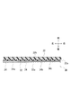
- FIG. 4 is a cross-sectional view of a collision detection sensor corresponding to line IV-IV in FIG. 3. It is a block diagram which shows the structure of a pedestrian protection system. It is a figure which shows the action
- the directions described in the description of the embodiments and the reference drawings indicate directions recognized by a driver seated on the vehicle unless otherwise specified.
- the direction of the arrow indicating “front” indicates the front of the vehicle.
- a pedestrian protection system vehicle collision detection device
- the vehicle collision detection device that is an aspect of the technology of the present disclosure is not intended only for detection of a pedestrian collision.
- the vehicle collision detection device of the present disclosure is intended for all collision detections that require a protection device to be operated, such as a bicycle or a stroller.
- a front bumper 21 is attached to the front end portion of the vehicle VE.
- the front bumper 21 extends in the left-right direction (vehicle width direction).
- the front bumper 21 includes a bumper cover 22 and a bumper absorber 23.
- the bumper cover 22 is made of, for example, a synthetic resin.
- the bumper cover 22 forms a design surface in the front portion of the vehicle VE.
- the bumper absorber 23 is provided behind the bumper cover 22 as a material (impact absorber) that absorbs the collision generated in the front bumper 21.
- the bumper absorber 23 is made of foamed resin such as foamed polypropylene, for example.
- the rear end surface 23 a of the bumper absorber 23 is attached to the front surface 24 a of the bumper reinforcement 24.
- the bumper reinforcement 24 is a strength member having a hollow interior made of a metal material such as an aluminum alloy.
- the bumper reinforcement 24 extends in the left-right direction.
- the bumper reinforcement 24 is fixed to front ends of a pair of left and right side members 25R and 25L extending in the front-rear direction.
- the body unit 2 is formed by the above-described front bumper 21, bumper reinforcement 24, and side members 25R and 25L.
- the collision detection sensor 3 is attached to the back surface 22a of the bumper cover 22 (the inner surface of the bumper cover 22).
- the collision detection sensor 3 extends in the left-right direction (vehicle width direction) so as to connect both end portions of the bumper cover 22. It is desirable that the collision detection sensor 3 is attached at a height position where a pedestrian or the like collides in the vehicle VE.
- the collision detection sensor 3 includes a plurality of sensor elements 31 and a base film 32.
- Each of the plurality of sensor elements 31 corresponds to a collision sensor and a sensor cell.
- the base film 32 holds the sensor element 31.
- the length of the collision detection sensor 3 in the left-right direction is schematically shown by contracting from the actual length.
- FIG. A configuration including a plurality of sensor elements 31 corresponds to a collision sensor.
- each sensor element 31 has a piezoelectric polymer film 31a and first and second divided electrodes 31b and 31c.
- the piezoelectric polymer film 31a is formed in a thin film shape.
- the piezoelectric polymer film 31a corresponds to a piezoelectric film and a divided piezoelectric film.
- the first and second divided electrodes 31b and 31c are formed in a flat plate shape.
- the first and second divided electrodes 31b and 31c are joined to the piezoelectric polymer film 31a.
- the first and second divided electrodes 31b and 31c correspond to a pair of electrodes and a pair of divided electrodes.
- FIGS. 3 and 6 only one element and electrode among the plurality of sensor elements 31 and the plurality of first divided electrodes 31 b are denoted by reference numerals.
- the piezoelectric polymer film 31a is formed of a piezoelectric polymer material such as polyvinylidene fluoride (PVDF), polypeptide, polylactic acid, polymethylglutamate, polybenzylglutamate, or the like.
- the first and second divided electrodes 31b and 31c are formed of a conductive metal film such as copper, aluminum, or silver paste, for example.
- the first and second divided electrodes 31b and 31c are arranged with the piezoelectric polymer film 31a sandwiched from both sides. In the following description, for convenience, the first and second divided electrodes 31b and 31c are collectively referred to as divided electrodes 31b and 31c.
- the base film 32 is formed in a film shape from, for example, a synthetic resin material.
- the base film 32 is interposed between the sensor element 31 and the back surface 22 a of the bumper cover 22.
- One surface 32a of the base film 32 is joined to the surface of the second divided electrode 31c that is not attached to the piezoelectric polymer film 31a. Therefore, as illustrated in FIG. 3, the plurality of sensor elements 31 are arranged on the base film 32 so as to form columns and rows. Further, the plurality of sensor elements 31 are held in a state where adjacent elements are separated from each other.
- Each sensor element 31 is bonded to the base film 32 by, for example, an adhesive or a double-sided adhesive tape.
- the surface 32 b (hereinafter referred to as “other surface 32 b”) of the base film 32 that is not joined to the second divided electrode 31 c is attached to the back surface 22 a of the bumper cover 22.
- the base film 32 has a substantially rectangular shape.
- the base film 32 is attached to the bumper cover 22 at the four fixing portions CP to which the sensor element 31 is not bonded.
- the base film 32 is bonded to the bumper cover 22 by, for example, an adhesive or a double-sided adhesive tape.
- the bumper cover 22 is deformed by a collision.
- the base film 32 is deformed together with the bumper cover 22.
- the sensor element 31 is deformed in a pulling direction (stretching direction) or a contracting direction (shrinking direction).
- the sensor element 31 generates an output voltage between the first divided electrode 31b and the second divided electrode 31c.
- the sensor element 31 generates a predetermined output voltage Vpz (hereinafter referred to as “piezo film voltage Vpz”) according to the deformation amount of the element between the first divided electrode 31b and the second divided electrode 31c.
- a piezoelectric polymer film having the above characteristics is publicly known. For example, it is disclosed in Japanese Patent Application Laid-Open Nos. 2004-96980, 2007-212436, 2013-29368, and the like, which are public patent publications.
- the speed sensor 4 detects the traveling speed (vehicle speed) of the vehicle VE.
- the speed sensor 4 is attached to a wheel or a transmission of the vehicle VE.
- the cowl airbag device 51 is one of the protection devices 5 (pedestrian protection devices) included in the vehicle VE.
- the cowl airbag device 51 operates the airbag from the engine hood HE to the lower portion of the front window WF when a pedestrian collides with the front bumper 21. This protects pedestrians and the like that collided (impacts).
- the pop-up hood 52 is one of the protection devices 5 provided in the vehicle VE.
- the pop-up hood 52 raises the rear end of the engine hood HE when a pedestrian or the like collides with the front bumper 21.
- the engine hood HE serves as a buffer member for the collision object. This prevents a pedestrian from colliding with an engine or the like (a member having rigidity), and protects the collided pedestrian or the like.
- the instrument panel 6 is provided in front of the driver's seat of the vehicle VE. When the instrument panel 6 detects a mounting failure of the sensor element 31 via the base film 32 to the bumper cover 22, the instrument panel 6 warns the driver. In addition, about a warning method, the display of a detection result, an audio
- the expression “attaching the sensor element 31 to the bumper cover 22 via the base film 32” may be expressed as “attaching the sensor element 31 to the bumper cover 22” for convenience.
- a pedestrian protection ECU 7 is attached to a floor tunnel (not shown) on the front side of the driver's seat.
- the pedestrian protection ECU 7 is a control device including an input / output device (for example, an I / O port), a CPU, a RAM, a ROM, and the like.
- the collision detection sensor 3, the speed sensor 4, the cowl airbag device 51, the pop-up hood 52, and the instrument panel 6 described above are connected to the pedestrian protection ECU 7 via a communication line.
- the pedestrian protection ECU 7 includes a vehicle speed determination unit 71, a collision determination unit 72, a deformation action unit 73, an attachment state determination unit 74, an AND circuit 75, and a protection device driver 76.
- the vehicle speed determination unit 71 is connected to the speed sensor 4.
- the vehicle speed determination unit 71 compares the vehicle speed detection value Sdet input from the speed sensor 4 with predetermined first and second vehicle speed thresholds Sth1, Sth2.
- the vehicle speed determination unit 71 determines whether the vehicle speed detection value Sdet is greater than or equal to the first vehicle speed threshold Sth1 and less than or equal to the second vehicle speed threshold Sth2 that is greater than the first vehicle speed threshold Sth1.
- the vehicle speed determination unit 71 determines whether or not the vehicle speed detection value Sdet is a value within the range from the first vehicle speed threshold value Sth1 to the second vehicle speed threshold value Sth2 (Sth1 ⁇ Sdet ⁇ Sth2).
- the vehicle speed determination unit 71 outputs a high (H) signal when the vehicle speed detection value Sdet is equal to or greater than the first vehicle speed threshold value Sth1 and equal to or less than the second vehicle speed threshold value Sth2.
- the vehicle speed determination unit 71 outputs a low (L) signal when the vehicle speed detection value Sdet is less than the first vehicle speed threshold value Sth1 or greater than the second vehicle speed threshold value Sth. That is, the vehicle speed determination unit 71 outputs a low (L) signal when the vehicle speed detection value Sdet is a value outside the range from the first vehicle speed threshold value Sth1 to the second vehicle speed threshold value Sth2.
- the collision determination unit 72 is connected to the collision detection sensor 3.
- the collision determination unit 72 compares the piezo film voltage Vpz input from the sensor element 31 (an output signal generated by the collision detection sensor 3) with a predetermined voltage threshold Vth.
- the collision determination unit 72 determines whether or not the piezo film voltage Vpz is equal to or higher than the voltage threshold Vth. Thereby, the collision determination unit 72 determines whether or not a collision that requires the operation of the protection device 5 has occurred in the bumper cover 22. That is, the collision determination unit 72 detects that a collision requiring the operation of the protection device 5 has occurred in the bumper cover 22.
- the collision determination unit 72 determines that a collision that requires the operation of the protection device 5 has occurred in the bumper cover 22 and outputs a high (H) signal.
- the collision determination unit 72 determines that a collision that requires the operation of the protection device 5 has not occurred, and outputs a low (L) signal.
- the collision determination unit 72 may perform the following collision determination. Specifically, the collision determination unit 72 determines whether or not the voltage (calculation voltage) calculated based on the piezo film voltage Vpz is equal to or higher than a predetermined voltage threshold Vth. The collision determination unit 72 may determine that a collision requiring the operation of the protection device 5 has occurred in the bumper cover 22 when the calculated voltage is equal to or higher than the voltage threshold Vth.
- the deformation acting portion 73 applies a load to the portion of the base film 32 that is not joined to the bumper cover 22 to deform the base film 32. At this time, the deformation acting part 73 is changed in the direction in which the base film 32 is pulled.
- the attachment state determination unit 74 determines the deformation voltage Vdg (corresponding to the first signal) generated between the first divided electrode 31b and the second divided electrode 31c. Is detected. The attachment state determination unit 74 determines whether or not the sensor element 31 is attached to the bumper cover 22 based on the deformation voltage Vdg.
- the attachment state determination unit 74 outputs a high (H) signal when it is determined that no attachment failure of the sensor element 31 has occurred with respect to the bumper cover 22. On the other hand, when the attachment state determination unit 74 determines that the attachment failure of the sensor element 31 has occurred with respect to the bumper cover 22, the attachment state determination unit 74 outputs a low (L) signal. At this time, the attachment state determination unit 74 warns the driver via the instrument panel 6 to that effect.
- the details of the method of deforming the base film 32 and the details of the method of determining whether or not the sensor element 31 is attached to the bumper cover 22 will be described later. Hereinafter, the expression “determining whether or not the sensor element 31 is poorly attached to the bumper cover 22” may be expressed as “defect attachment determination” for convenience.
- Each of the three input terminals of the AND circuit 75 is connected to a vehicle speed determination unit 71, a collision determination unit 72, and an attachment state determination unit 74. Therefore, output signals from the vehicle speed determination unit 71, the collision determination unit 72, and the attachment state determination unit 74 are input to the AND circuit 75.
- the AND circuit 75 outputs a high (H) signal when a high (H) signal is input from all of the vehicle speed determination unit 71, the collision determination unit 72, and the attachment state determination unit 74. That is, the AND circuit 75 outputs a low (L) signal when a low (L) signal is input from at least one of the vehicle speed determination unit 71, the collision determination unit 72, and the attachment state determination unit 74. .
- the protection device driver 76 is connected to the output terminal of the AND circuit 75.
- the protection device driver 76 activates the protection device 5 (for example, the cowl airbag device 51 or the pop-up hood 52) when a high (H) signal is input from the AND circuit 75.
- the deformation action unit 73 selects one or a plurality of elements to be deformed by applying a load from the sensor elements 31. And the deformation
- the expression “sensor element 31S” may be expressed as “deformation element 31S” for convenience.
- the base film 32 is fixed to the bumper cover 22 at the four fixing portions CP. Therefore, the base film 32 is deformed in the pulling direction due to the contraction of the deformation element 31S. And by deformation
- a predetermined deformation voltage Vdg first signal
- sensor element 31D may be expressed as “detection element 31D (detection cell)” for convenience.
- the driving voltage Vip is not applied to the detection element 31D by the deformation acting portion 73 (no load is applied). Further, it is desirable that the detection element 31D is adjacent to the deformation element 31S. However, the detection element 31D does not necessarily have to be adjacent to the deformation element 31S. The detection element 31D may be at a position away from the deformation element 31S within a range in which the deformation voltage Vdg can be separated from electrical noise.
- the attachment state determination unit 74 stores a predetermined specified voltage Vfx.
- the specified voltage Vfx (corresponding to the second signal) is a deformed voltage Vdg generated in the detection element 31D when the drive voltage Vip is applied to the deforming element 31S in such a normal state.
- the specified voltage Vfx is obtained based on the results of experiments performed in advance.
- the normal state is a state in which the base film 32 is normally attached to the bumper cover 22 and the sensor element 31 is normally attached to the base film 32.
- the specified voltage Vfx is obtained experimentally in advance.
- the deformation voltage Vdg generated in the detection element 31D has a value different from the specified voltage Vfx.
- the defective state is a state caused by at least one of peeling of the base film 32 with respect to the bumper cover 22 and peeling of the sensor element 31 with respect to the base film 32.
- the base film 32 is peeled off from the bumper cover 22.
- the drive voltage Vip is applied to the deformation element 31S.
- the detection element 31D does not generate a predetermined deformation voltage Vdg (first signal).
- Vdg first signal
- the deformation element 31 ⁇ / b> S is peeled off from the base film 32. In such a state, it is assumed that the drive voltage Vip is applied to the deformation element 31S.
- the deformation element 31S since the deformation element 31S is peeled off, deformation due to voltage application is not transmitted from the deformation element 31S to the base film 32. Further, it is assumed that the detection element 31D is peeled off from the base film 32. In such a state, it is assumed that the drive voltage Vip is applied to the deformation element 31S. As a result, since the detection element 31D is peeled off, even if a predetermined deformation occurs in the base film 32, the deformation is not transmitted to the detection element 31D. For this reason, the detection element 31D does not generate a predetermined deformation voltage Vdg (first signal).
- the attachment state determination unit 74 determines whether or not the sensor element 31 is defectively attached to the bumper cover 22. judge. Specifically, the attachment state determination unit 74 calculates the difference (absolute value) between the deformation voltage Vdg and the specified voltage Vfx for each of the plurality of detection elements 31D. The attachment state determination unit 74 determines whether or not the calculated difference is a predetermined amount of the determination condition. The attachment state determination unit 74 causes the attachment failure of the sensor element 31 when there is at least one element (the difference is larger than the reference deviation) whose difference is a predetermined amount among the plurality of detection elements 31D. It is determined that
- the attachment state determination unit 74 may determine the attachment failure of the sensor element 31 as follows. Specifically, in the attachment failure determination, the deformation element 31S and the detection element 31D are changed among the plurality of sensor elements 31. The attachment state determination unit 74 sequentially performs the application of the drive voltage Vip to the deformation element 31S and the detection of the deformation voltage Vdg generated in the detection element 31D. As described above, in the attachment defect determination, the element change and the voltage detection may be repeatedly performed. Moreover, the implementation timing of attachment defect determination is not specifically limited. For example, as illustrated in FIG. 8, the attachment defect determination may be performed every time the control process of the pedestrian protection system 1 (the vehicle collision detection device) is executed. Further, the attachment failure determination may be performed immediately after the ignition switch of the vehicle VE is turned on. The attachment failure determination may be repeated every time a predetermined time elapses while the ignition switch is turned on.
- control process which shows the control method of the pedestrian protection system 1 (collision detection apparatus for vehicles) is demonstrated.
- This process is executed by the pedestrian protection ECU 7. More specifically, this process is executed by the vehicle speed determination unit 71, the collision determination unit 72, the deformation action unit 73, the attachment state determination unit 74, the AND circuit 75, and the protection device driver 76 that are included in the pedestrian protection ECU 7.
- the pedestrian protection ECU 7 applies a predetermined drive voltage Vip to the deformation element 31S by the deformation action unit 73 (step S101).
- the pedestrian protection ECU 7 detects the deformation voltage Vdg (first signal) generated in the detection element 31D by the attachment state determination unit 74 (step S102). Thereafter, the attachment state determination unit 74 calculates a difference
- the attachment state determination unit 74 determines that the difference
- the sensor element It is determined that the attachment failure 31 has occurred.
- the attachment state determination unit 74 outputs a low (L) signal to the AND circuit 75.
- the attachment state determination part 74 warns through the instrument panel 6 that the attachment defect of the sensor element 31 with respect to the bumper cover 22 has generate
- step S103 determines that the difference
- a defective attachment of the sensor element 31 occurs. Judge that it is not.
- the attachment state determination unit 74 outputs a high (H) signal to the AND circuit 75. Thereafter, the vehicle speed detection value Sdet of the vehicle VE is input from the speed sensor 4 to the vehicle speed determination unit 71 (step S104).
- the pedestrian protection ECU 7 determines whether the vehicle speed detection value Sdet is a value within the range from the first vehicle speed threshold value Sth1 to the second vehicle speed threshold value Sth2 (Sth1 ⁇ Sdet ⁇ Sth2) by the vehicle speed determination unit 71 (step S1). S105). Specifically, the vehicle speed determination unit 71 determines whether or not the vehicle speed detection value Sdet is equal to or greater than the first vehicle speed threshold Sth1 and equal to or less than the second vehicle speed threshold Sth2. As a result, when the vehicle speed determination unit 71 determines that the vehicle speed detection value Sdet is less than the first vehicle speed threshold value Sth1 or greater than the second vehicle speed threshold value Sth2 (step S105: No), the AND circuit 75 is set to low (L).
- step S105 Yes
- the AND circuit 75 is set to high ( H) Output a signal.
- the piezo film voltage Vpz is input from the sensor element 31 to the collision determination unit 72 (step S106).
- the pedestrian protection ECU 7 uses the collision determination unit 72 to determine whether or not the piezo film voltage Vpz is equal to or higher than the voltage threshold Vth (step S107).
- the voltage threshold Vth at this time is set as follows. For example, a piezo film voltage generated when a pedestrian or a bicycle collides with the bumper cover 22 is assumed to be Vpz1. On the other hand, a piezoelectric film voltage generated when an object (such as a ground structure) other than a pedestrian or a bicycle collides with the bumper cover 22 is defined as Vpz2. In this case, the voltage threshold Vth is set to a value between Vpz1 and Vpz2.
- step S107: Yes when the collision determination unit 72 determines that the piezo film voltage Vpz is equal to or higher than the voltage threshold Vth (step S107: Yes), a collision that requires the operation of the protection device 5 has occurred in the bumper cover 22. (Step S108).
- the collision determination unit 72 outputs a high (H) signal to the AND circuit 75.
- the protection device driver 76 operates the protection device 5 based on the output signal of the AND circuit 75 (step S109).
- step S107: No when the collision determination unit 72 determines that the piezo film voltage Vpz is less than the voltage threshold Vth (step S107: No), the collision determination unit 72 outputs a low (L) signal to the AND circuit 75.
- the pedestrian protection system 1 (vehicle collision detection device) includes the attachment state determination unit 74 that determines whether or not the sensor element 31 is attached to the bumper cover 22.
- the attachment state determination unit 74 is configured so that the sensor element 31 is connected via the deformation voltage Vdg (first signal) generated by the sensor element 31 when the base film 32 is deformed by the deformation action unit 73 and the base film 32. Based on the specified voltage Vfx (second signal) when normally attached to the bumper cover 22, whether or not the sensor element 31 is attached to the bumper cover 22 is determined.
- the pedestrian protection system 1 it is possible to detect a mounting failure of the sensor element 31 with respect to the bumper cover 22 due to the base film 32 being peeled from the bumper cover 22.
- the pedestrian protection system 1 it is possible to detect a mounting failure of the sensor element 31 with respect to the bumper cover 22 due to the sensor element 31 being peeled from the base film 32. Therefore, in this embodiment, when the attachment failure of the sensor element 31 occurs, the driver of the vehicle VE is warned and the operation of the pedestrian protection system 1 can be stopped. Therefore, in this embodiment, the reliable pedestrian protection system 1 can be provided.
- the deformation acting unit 73 selects the deformation element 31S to be deformed by applying a load from the plurality of sensor elements 31. And the deformation
- the pedestrian protection system 1 it is possible to determine the attachment failure of the sensor element 31 using only the sensor element 31 for detecting a collision. Therefore, in the present embodiment, a special actuator or the like that deforms the base film 32 is not required for determining attachment failure of the sensor element 31.
- transformation element 31S can be detected easily. Therefore, in this embodiment, it is possible to accurately determine the attachment failure of the sensor element 31 with respect to the bumper cover 22.
- the base film 32 has a substantially rectangular shape. The base film 32 is attached to the bumper cover 22 at the four fixing portions CP to which the sensor element 31 is not bonded.
- the attachment process of the base film 32 with respect to the bumper cover 22 can be simplified. Further, in the pedestrian protection system 1, parts of the base film 32 other than the four fixed portions CP that are joined to the bumper cover 22 can be deformed. Therefore, in this embodiment, the base film 32 has a wide range in which the deformable element 31S can be arranged.
- the peripheral edge fixing portion FP is a peripheral edge portion of the base film 32 including an upper edge portion, a lower edge portion, a left edge portion, and a right edge portion.
- the base film 32 is fixed to the bumper cover 22 in such a peripheral edge fixing portion FP.
- Other configurations of the collision detection sensor 3 of the present modification are the same as those of the first embodiment. Therefore, further explanation is omitted.
- the base film 32 has a substantially rectangular shape.
- the base film 32 is attached to the bumper cover 22 in the peripheral edge fixing portion FP to which the sensor element 31 is not bonded.
- the base film 32 is firmly attached to the bumper cover 22.
- the base film 32 can be deformed at any position of the portion surrounded by the peripheral edge fixing portion FP. Therefore, in this modification, it is possible to easily determine whether or not the sensor element 31 is attached to the bumper cover 22.
- FIG. 10 the attachment method to the bumper cover 22 of the collision detection sensor 3 which concerns on the 2nd modification of 1st Embodiment is demonstrated.
- the length of the collision detection sensor 3 in the left-right direction is schematically represented by being contracted from the actual length.
- the base film 32 of this modification has a substantially rectangular shape as in the first embodiment.
- the plurality of sensor elements 31 are arranged in the base film 32 so as to form columns and rows.
- the base film 32 is attached to the bumper cover 22 at the inter-row fixing part BP and the upper and lower edge fixing parts OP.
- the inter-column fixing portion BP corresponds to a portion of the base film 32 that is positioned between adjacent rows of the sensor elements 31.
- the upper and lower edge fixing portion OP is an edge portion of the base film 32 including an upper edge portion and a lower edge portion to which the sensor element 31 is not joined.
- the reason why it is described as “corresponding to a part” in the description of the inter-column fixing portion BP is as follows.
- the sensor element 31 is attached to one surface 32 a of the base film 32.
- the base film 32 is attached to the bumper cover 22 via the other surface 32b different from the one surface 32a.
- the mounting surface of the sensor element 31 and the mounting surface of the bumper cover 22 are not on the same surface in the base film 32. Further, the base film 32 may be attached to the bumper cover 22 at a portion located between adjacent columns of the sensor elements 31.
- Other configurations of the collision detection sensor 3 of the present modification are the same as those of the first embodiment. Therefore, further explanation is omitted.
- the base film 32 is attached to the bumper cover 22 at the inter-row fixing portion BP located between the adjacent rows of the sensor elements 31.
- the attachment position to the bumper cover 22 is provided equally. Therefore, in the present modification, the collision occurring in the bumper cover 22 can be detected with high accuracy by the collision detection sensor 3.
- transformation element 31S and the detection element 31D are arrange
- the collision detection sensor 3A according to the second embodiment includes a base film 32 as illustrated in FIG.
- the base film 32 has a substantially rectangular shape as in the first embodiment.
- the base film 32 is attached to the bumper cover 22 at the four fixing portions CP to which the sensor element 31 is not bonded.
- a plurality of actuator metal pieces 33 (deformation action portions) are formed on the base film 32. As illustrated in FIG. 11, each of the plurality of actuator metal pieces 33 is disposed between adjacent rows of sensor elements 31. As shown by the broken lines in FIG. 11, each of the plurality of actuator metal pieces 33 may be disposed between adjacent columns of the sensor elements 31.
- Each of the plurality of actuator metal pieces 33 is made of, for example, a shape memory alloy.
- the actuator metal piece 33 is fixed to the base film 32 over its entire length.
- the deformation acting part 73 deforms the base film 32 using the actuator metal piece 33 instead of deforming the base film 32 by contraction of the sensor element 31 (the deformation element 31S).
- the deforming action portion 73 causes an electric current to flow through the actuator metal piece 33 to generate heat.
- the actuator metal piece 33 is deformed.
- transformation action part 73 is deform
- the attachment state determination unit 74 detects the deformation voltage Vdg (first signal) generated in one of the sensor elements 31 (detection element 31D). To do.
- the attachment state determination unit 74 determines whether or not the sensor element 31 is attached to the bumper cover 22 based on the deformation voltage Vdg. In the present embodiment, even if each of the actuator metal pieces 33 is disposed between adjacent columns of the sensor elements 31, it functions in the same manner as described above. Other configurations of the present embodiment are the same as those of the first embodiment. Further, the method for determining the attachment failure of the sensor element 31 according to the present embodiment is the same as that of the first embodiment. Therefore, further explanation is omitted.
- the deformation acting portion 73 causes an electric current to flow through the actuator metal piece 33 provided on the base film 32 to generate heat. As a result, the actuator metal piece 33 is deformed. As described above, the deformation acting portion 73 deforms the base film 32 by the deformation of the actuator metal piece 33. As a result, the sensor element 31 disposed on the base film 32 is greatly deformed as compared with the configuration of the first embodiment. Thereby, in this embodiment, the deformation voltage Vdg can be easily separated from the electric noise. Therefore, in this embodiment, the attachment defect determination of the sensor element 31 can be performed with high accuracy, and the pedestrian protection system 1 with higher reliability can be provided.
- the attachment failure determination does not affect the function of the sensor element 31.
- Each of the actuator metal pieces 33 is disposed between adjacent rows of the sensor elements 31. Thereby, in this embodiment, the arrangement
- the collision detection sensor 3B according to the third embodiment will be described with reference to FIGS.
- the length of the collision detection sensor 3 ⁇ / b> B in the left-right direction is schematically illustrated by being contracted from the actual length.
- the collision detection sensor 3 ⁇ / b> B of the present embodiment includes a sensor element 34 (collision sensor) and a base film 32.
- the sensor element 34 of the present embodiment is not divided into a plurality of parts.
- the sensor element 34 is integrally formed.
- the sensor element 34 includes a piezoelectric polymer film 34 a (piezoelectric film) and first and second electrodes 34 b and 34 c.
- the first and second electrodes 34b and 34c are formed in a flat plate shape.
- the first and second electrodes 34b and 34c are formed so as to sandwich both surfaces of the piezoelectric polymer film 34a.
- the first and second electrodes 34b and 34c correspond to a pair of electrodes.
- the sensor element 34 generates a piezo film voltage Vpz (predetermined output voltage) between the first electrode 34b and the second electrode 34c in accordance with the deformation amount of the element.
- one surface 32a of the base film 32 is joined to the surface of the second electrode 34c that is not attached to the piezoelectric polymer film 34a.
- Each sensor element 34 is bonded to the base film 32 by, for example, an adhesive or a double-sided adhesive tape.
- the other surface 32 b of the base film 32 is attached to the back surface 22 a of the bumper cover 22.
- the base film 32 has a substantially rectangular shape. The base film 32 is attached to the bumper cover 22 at the four fixing portions CP to which the sensor element 34 is not bonded.
- the upper end input point UP formed on the upper edge and the side end input point SP formed on the right side are respectively provided with the deformation acting device 35 (the deformation acting portion). Control target device) is connected.
- the upper end input point UP and the side end input point SP are formed at positions different from the four fixed portions CP.
- the deformation device 35 is configured by, for example, an electromagnetic actuator or an electrostatic actuator.
- the deformation device 35 may be formed of, for example, a piezoelectric element or a shape memory alloy.
- the deformation acting part 73 deforms the base film 32 using the deformation acting device 35 instead of deforming the base film 32 by contraction of the sensor element 31.
- the deformation action unit 73 operates the deformation action device 35. As a result, the deformation device 35 pulls the upper end input point UP of the base film 32 upward. Alternatively, the deformation device 35 pulls the side end input point SP to the right.
- the attachment state determination unit 74 detects the deformation voltage Vdg (first signal) generated in the sensor element 34.
- the attachment state determination unit 74 determines the presence or absence of attachment failure of the sensor element 34 to the bumper cover 22 based on the deformation voltage Vdg.
- the deformation device 35 does not need to be connected to both the upper end input point UP and the side end input point SP.
- the deformation device 35 may be connected to one of the upper end input point UP and the side end input point SP.
- the deformation device 35 may be connected to the lower edge or the left side of the base film 32.
- the sensor element 34 may be divided into a plurality of sensor elements 31 as in the first embodiment. Other configurations of the present embodiment are the same as those of the first embodiment. Further, the method for determining the attachment failure of the sensor element 31 according to the present embodiment is the same as that of the first embodiment. Therefore, further explanation is omitted.
- the technique of this indication is not limited to embodiment mentioned above.
- the technology of the present disclosure can be modified or expanded as follows.
- the base film 32 when determining whether or not the sensor element 31 is poorly attached to the bumper cover 22, the base film 32 does not necessarily have to be deformed.
- the base film 32 may be deformed in the shrinking direction, the deformation voltage Vdg generated along with the deformation may be detected, and the presence / absence of attachment failure of the sensor element 31 may be determined.
- the actuator metal piece 33 is attached to the peripheral part of the base film 32 in 2nd Embodiment. And in the pedestrian protection system 1, you may join the sensor element 34 integrally formed to the base film 32 similarly to 3rd Embodiment.
- Pedestrian protection system (vehicle collision detection device) 5: Protection device (pedestrian protection device) 22: Bumper cover 31: Sensor element (collision sensor and sensor cell) 31a: Piezoelectric polymer film (piezoelectric film and divided piezoelectric film) 31b: First divided electrode (electrode and divided electrode) 31c: Second divided electrode (electrode and divided electrode) 31D: Detection element (detection cell) 31S: Deformation element 32: Base film 33: Actuator metal piece (shape memory alloy) 34: Sensor element (collision sensor) 34a: Piezoelectric polymer film (piezoelectric film) 34b: First electrode (electrode) 34c: Second electrode (electrode) 35: Deformation action device 72: Collision determination part 73: Deformation action part 74: Attachment state determination part VE: Vehicle
Landscapes
- Engineering & Computer Science (AREA)
- Mechanical Engineering (AREA)
- Physics & Mathematics (AREA)
- General Physics & Mathematics (AREA)
- Force Measurement Appropriate To Specific Purposes (AREA)
Abstract
車両のバンパーカバーの裏面には、衝突検知センサ3が取り付けられている。衝突検知センサ3は、基材フィルム32と複数のセンサ素子31とを含む。基材フィルム32は、4つの固定部がバンパーカバーに取り付けられている。複数のセンサ素子31は、隣接した素子同士が互いに離れた状態で基材フィルム32上に保持されている。センサ素子31それぞれは、一対の分割電極31b,31cが圧電性高分子フィルム31aを挟んで形成されている。歩行者保護ECUは、変形作用部と取付状態判定部とを有する。変形作用部は、いずれかのセンサ素子に駆動電圧Vipを印加して、基材フィルム32を変形させる。取付状態判定部は、電圧が印加されていないセンサ素子31Dに発生した変形電圧Vdgに基づいて、バンパーカバーに対するセンサ素子31の取付不良の有無を判定している。
Description
本開示は、車両への歩行者等の衝突を検出する技術に関する。
従来、ハウジング内に、圧電フィルムを含んだ複数の衝突センサと、信号処理装置と、を有する車両用センサモジュールがある。衝突検知装置は、このような車両用センサモジュールが、バンパーカバーの後方に取り付けられている(例えば、特許文献1参照)。当該衝突検知装置では、バンパーカバーに歩行者等の衝突が発生した場合、次のようにその衝突を検知している。具体的には、衝突センサは、衝突によって発生したひずみに応じて出力信号を生成する。信号処理装置は、当該出力信号に基づいて、車両への衝突を検知する。
ところで、上述した衝突検知装置において、バンパーカバーに発生した衝突を正確に検知するためには、バンパーカバーに対して、衝突センサが確実に固定されている必要がある。通常、衝突センサは、接着剤または両面接着テープによって、バンパーカバーに接合されて取り付けられている。このため、接合部位への泥水等の付着、周辺温度の変化、車体部品の経時変化等により、バンパーカバーと衝突センサとの間の接合力が低下することが考えられる。このような接合力の低下により、バンパーカバーから衝突センサの一部が剥離した場合には、車両への衝突の発生を正確に検知することが困難になる。したがって、この場合には、衝突検知装置の作動を停止させる。そのため、バンパーカバーからの衝突センサの剥離を正確に検出する必要があった。
本開示は、バンパーカバーに対する衝突センサの取付状態を正確に判定でき、信頼性の高い車両用衝突検知技術を提供する。
本開示は、バンパーカバーに対する衝突センサの取付状態を正確に判定でき、信頼性の高い車両用衝突検知技術を提供する。
本開示の技術の一態様である車両用衝突検知装置は、衝突センサ、基材フィルム、および衝突判定部を備える。衝突センサは、圧電フィルムおよび当該圧電フィルムの両面を挟む一対の平板状の電極を含む。衝突センサは、衝突による変形に応じて、電極の間に所定の出力信号を生成する。基材フィルムは、衝突センサと、車両のバンパーカバーの内側面と、の間に介装されている。衝突判定部は、衝突センサによって生成された出力信号に基づき、衝突物を保護する保護装置の作動を必要とする衝突が、バンパーカバーにおいて発生したか否かを判定する。さらに、車両用衝突検知装置は、変形作用部および取付状態判定部を備える。変形作用部は、バンパーカバーに接合されていない基材フィルムの部位に対して荷重をかけ、基材フィルムを変形させる。取付状態判定部は、変形作用部によって基材フィルムが変形された場合に衝突センサが発生する出力信号である第1信号と、基材フィルムを介して、衝突センサがバンパーカバーに正常に取り付けられている場合に衝突センサが発生する出力信号である第2信号と、に基づいて、バンパーカバーに対する衝突センサの取付不良の有無を判定する。
この構成によれば、本開示の技術の一態様である車両用衝突検知装置は、バンパーカバーに対する衝突センサの取付不良の有無を判定する取付状態判定部を備える。具体的には、取付状態判定部は、変形作用部によって基材フィルムが変形された場合に発生する第1信号と、基材フィルムを介して、衝突センサがバンパーカバーに正常に取り付けられている場合に発生する第2信号と、に基づいて、バンパーカバーに対する衝突センサの取付不良の有無を判定する。これにより、車両用衝突検知装置は、基材フィルムがバンパーカバーから剥離したことに起因する、バンパーカバーに対する衝突センサの取付不良を検知できる。または、車両用衝突検知装置は、衝突センサが基材フィルムから剥離したことに起因する、バンパーカバーに対する衝突センサの取付不良を検知できる。したがって、本開示の技術は、衝突センサの取付不良が発生した場合、運転者に警告するとともに、車両用衝突検知装置の作動を停止できる。よって、本開示の技術では、信頼性の高い車両用衝突検知装置を提供できる。
なお、本開示の車両用衝突検知装置は、歩行者の衝突の検知のみを対象としているのではない。本開示の車両用衝突検知装置は、保護装置を作動させる必要のあるすべての衝突検知を対象としている。
なお、本開示の車両用衝突検知装置は、歩行者の衝突の検知のみを対象としているのではない。本開示の車両用衝突検知装置は、保護装置を作動させる必要のあるすべての衝突検知を対象としている。
以下、本開示の技術の実施形態について説明する。なお、実施形態の説明および参照図面に記載の方向は、特に明記しない限り、車両に着座した運転者が認識する方向を示す。例えば、図中において、「前」を示す矢印の方向は、車両の前方を示している。また、以降の実施形態では、その説明を分かり易くするために、車両に対する歩行者の衝突を想定した、歩行者保護システム(車両用衝突検知装置)を例に説明する。上述したように、本開示の技術の一態様である車両用衝突検知装置は、歩行者の衝突の検知のみを対象としているのではない。本開示の車両用衝突検知装置は、例えば、自転車やベビーカー等、保護装置を作動させる必要のあるすべての衝突検知を対象としている。
<第1実施形態>
図1から図8に基づいて、第1実施形態に係る歩行者保護システム1について説明する。
(歩行者保護システムの全体構成)
図1に例示するように、車両VEの前端部には、フロントバンパー21が取り付けられている。フロントバンパー21は、左右方向(車幅方向)に延びている。フロントバンパー21は、バンパーカバー22とバンパーアブソーバー23とを含んでいる。バンパーカバー22は、例えば、合成樹脂によって形成されている。バンパーカバー22は、車両VEの前方部における意匠面を成している。バンパーアブソーバー23は、フロントバンパー21において発生した衝突を吸収する材料(衝撃吸収材)として、バンパーカバー22の後方に設けられている。バンパーアブソーバー23は、例えば、発泡ポリプロピレン等の発泡樹脂によって形成されている。
図1から図8に基づいて、第1実施形態に係る歩行者保護システム1について説明する。
(歩行者保護システムの全体構成)
図1に例示するように、車両VEの前端部には、フロントバンパー21が取り付けられている。フロントバンパー21は、左右方向(車幅方向)に延びている。フロントバンパー21は、バンパーカバー22とバンパーアブソーバー23とを含んでいる。バンパーカバー22は、例えば、合成樹脂によって形成されている。バンパーカバー22は、車両VEの前方部における意匠面を成している。バンパーアブソーバー23は、フロントバンパー21において発生した衝突を吸収する材料(衝撃吸収材)として、バンパーカバー22の後方に設けられている。バンパーアブソーバー23は、例えば、発泡ポリプロピレン等の発泡樹脂によって形成されている。
バンパーアブソーバー23の後端面23aは、バンパーリインフォースメント24の前面24aに取り付けられている。バンパーリインフォースメント24は、例えば、アルミニウム合金等の金属材料によって、内部が中空に形成された強度部材である。バンパーリインフォースメント24は、左右方向に延びている。バンパーリインフォースメント24は、前後方向に延びた左右一対のサイドメンバ25R,25Lの前端部に固定されている。ボディーユニット2は、上述したフロントバンパー21、バンパーリインフォースメント24、および、サイドメンバ25R,25Lによって形成されている。
図1および図2に例示したように、バンパーカバー22の裏面22a(バンパーカバー22の内側面)には、衝突検知センサ3が取り付けられている。衝突検知センサ3は、バンパーカバー22の両端部をつなぐように、左右方向(車幅方向)に延在している。衝突検知センサ3は、車両VEにおいて、歩行者等が衝突する高さの位置に取り付けられていることが望ましい。
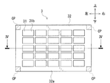
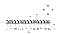
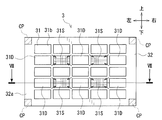
図3に例示したように、衝突検知センサ3は、複数のセンサ素子31と基材フィルム32とを含んでいる。複数のセンサ素子31それぞれは、衝突センサおよびセンサセルに該当する。基材フィルム32は、センサ素子31を保持する。なお、図3には、衝突検知センサ3の左右方向の長さを実際より縮めて模式的に表している。図6においても同様である。複数のセンサ素子31を含む構成は、衝突センサに該当する。図4に例示するように、各センサ素子31は、圧電性高分子フィルム31aと、第1および第2分割電極31b,31cと、を有している。圧電性高分子フィルム31aは、薄膜状に形成されている。圧電性高分子フィルム31aは、圧電フィルムおよび分割圧電フィルムに該当する。第1および第2分割電極31b,31cは、平板状に形成されている。第1および第2分割電極31b,31cは、圧電性高分子フィルム31aに接合されている。第1および第2分割電極31b,31cは、一対の電極および一対の分割電極に該当する。なお、図3および図6には、複数のセンサ素子31および複数の第1分割電極31bのうち、1つの素子および電極のみに符号を付している。
圧電性高分子フィルム31aは、例えば、ポリフッ化ビニリデン(PVDF)、ポリペプチド、ポリ乳酸、ポリメチルグルタメート、ポリベンジルグルタメート等の圧電性高分子材料によって形成されている。第1および第2分割電極31b,31cは、例えば、銅、アルミニウム、銀ペースト等の導電性を有する金属皮膜によって形成されている。第1および第2分割電極31b,31cは、圧電性高分子フィルム31aを両面から挟んで配置されている。以下の説明では、便宜上、第1および第2分割電極31b,31cをまとめて、分割電極31b,31cという。
基材フィルム32は、例えば、合成樹脂材料によってフィルム状に形成されている。基材フィルム32は、センサ素子31とバンパーカバー22の裏面22aとの間に介装されている。基材フィルム32の一面32aは、圧電性高分子フィルム31aに取り付けられていない、第2分割電極31cの面に接合されている。よって、図3に例示するように、複数のセンサ素子31は、基材フィルム32上において、縦列および横列を形成するように並べられている。さらに、複数のセンサ素子31は、隣接した素子同士が互いに離れた状態で保持されている。そして、各センサ素子31は、例えば、接着剤または両面接着テープによって基材フィルム32に接合されている。
第2分割電極31cに接合されていない、基材フィルム32の面32b(以下「他面32b」という)は、バンパーカバー22の裏面22aに取り付けられている。基材フィルム32は、略矩形状をしている。基材フィルム32は、センサ素子31が接合されていない4つの固定部CPにおいて、バンパーカバー22に取り付けられている。基材フィルム32は、例えば、接着剤または両面接着テープによってバンパーカバー22に接合されている。
バンパーカバー22は、衝突により変形する。その結果、基材フィルム32は、バンパーカバー22とともに変形する。基材フィルム32の変形によって、センサ素子31は、引っ張る方向(延伸方向)または縮む方向(収縮方向)に変形する。その結果、センサ素子31は、第1分割電極31bと第2分割電極31cと間に出力電圧を発生させる。具体的には、センサ素子31は、当該素子の変形量に応じた所定の出力電圧Vpz(以下「ピエゾフィルム電圧Vpz」という)を、第1分割電極31bと第2分割電極31cと間に発生させる。
また、それとは逆に、センサ素子31において、第1分割電極31bと第2分割電極31cと間に、所定の駆動電圧Vipが印加されたとする。これを受けて、センサ素子31は、引っ張る方向または縮む方向に変形する。なお、上記特徴を有する圧電性高分子フィルムは公知である。例えば、公開特許公報である特開2004-96980号公報、特開2007-212436号公報、および特開2013-29368号公報等に開示されている。
また、それとは逆に、センサ素子31において、第1分割電極31bと第2分割電極31cと間に、所定の駆動電圧Vipが印加されたとする。これを受けて、センサ素子31は、引っ張る方向または縮む方向に変形する。なお、上記特徴を有する圧電性高分子フィルムは公知である。例えば、公開特許公報である特開2004-96980号公報、特開2007-212436号公報、および特開2013-29368号公報等に開示されている。
図1の説明に戻る。速度センサ4は、車両VEの走行速度(車速)を検出する。速度センサ4は、車両VEの車輪またはトランスミッション等に取り付けられている。
カウルエアバッグ装置51は、車両VEが備える保護装置5(歩行者保護装置)のひとつである。カウルエアバッグ装置51は、フロントバンパー21に歩行者が衝突した場合に、エンジンフードHEからフロントウィンドウWFの下部に亘ってエアバッグを作動させる。これによって、衝突した歩行者等(衝突物)を保護する。
カウルエアバッグ装置51は、車両VEが備える保護装置5(歩行者保護装置)のひとつである。カウルエアバッグ装置51は、フロントバンパー21に歩行者が衝突した場合に、エンジンフードHEからフロントウィンドウWFの下部に亘ってエアバッグを作動させる。これによって、衝突した歩行者等(衝突物)を保護する。
ポップアップフード52は、車両VEが備える保護装置5のひとつである。ポップアップフード52は、フロントバンパー21に歩行者等が衝突した場合に、エンジンフードHEの後端を上昇させている。その結果、エンジンフードHEが、衝突物に対する緩衝部材となる。これによって、歩行者がエンジン等(剛性を有する部材)に衝突することを防ぎ、衝突した歩行者等を保護する。
インスツルメントパネル6は、車両VEの運転席の前方に設けられている。インスツルメントパネル6は、バンパーカバー22に対する、基材フィルム32を介したセンサ素子31の取付不良を検知した時に、運転者に対して、その旨を警告する。なお、警告方法については、例えば、検知結果の表示や音声出力等が挙げられる。以下、「バンパーカバー22に対する、基材フィルム32を介したセンサ素子31の取り付け」という表現は、便宜上、「バンパーカバー22に対するセンサ素子31の取り付け」と表現する場合がある。
インスツルメントパネル6は、車両VEの運転席の前方に設けられている。インスツルメントパネル6は、バンパーカバー22に対する、基材フィルム32を介したセンサ素子31の取付不良を検知した時に、運転者に対して、その旨を警告する。なお、警告方法については、例えば、検知結果の表示や音声出力等が挙げられる。以下、「バンパーカバー22に対する、基材フィルム32を介したセンサ素子31の取り付け」という表現は、便宜上、「バンパーカバー22に対するセンサ素子31の取り付け」と表現する場合がある。
(歩行者保護ECUの構成)
図1に例示するように、車両VEにおいて、運転席前側のフロアトンネル(非図示)には、歩行者保護ECU7が取り付けられている。歩行者保護ECU7は、入出力装置(例えばI/Oポート等)、CPU、RAM、ROM等を備える制御装置である。歩行者保護ECU7には、上述した、衝突検知センサ3、速度センサ4、カウルエアバッグ装置51、ポップアップフード52、およびインスツルメントパネル6が、通信線を介して接続されている。
図1に例示するように、車両VEにおいて、運転席前側のフロアトンネル(非図示)には、歩行者保護ECU7が取り付けられている。歩行者保護ECU7は、入出力装置(例えばI/Oポート等)、CPU、RAM、ROM等を備える制御装置である。歩行者保護ECU7には、上述した、衝突検知センサ3、速度センサ4、カウルエアバッグ装置51、ポップアップフード52、およびインスツルメントパネル6が、通信線を介して接続されている。
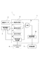
図5に例示するように、歩行者保護ECU7は、車速判定部71、衝突判定部72、変形作用部73、取付状態判定部74、AND回路75、および保護装置ドライバー76を含んでいる。
車速判定部71は、速度センサ4に接続されている。車速判定部71は、速度センサ4から入力された車速検出値Sdetと、所定の第1および第2車速閾値Sth1,Sth2と、を比較する。車速判定部71は、車速検出値Sdetが、第1車速閾値Sth1以上であり、かつ、第1車速閾値Sth1より大きい第2車速閾値Sth2以下であるか否かを判定する。つまり、車速判定部71は、車速検出値Sdetが、第1車速閾値Sth1から第2車速閾値Sth2までの範囲内の値(Sth1≦Sdet≦Sth2)か否かを判定する。車速判定部71は、車速検出値Sdetが、第1車速閾値Sth1以上であり、かつ、第2車速閾値Sth2以下である場合に、ハイ(H)信号を出力する。一方、車速判定部71は、車速検出値Sdetが、第1車速閾値Sth1未満、または、第2車速閾値Sthより大きい場合に、ロー(L)信号を出力する。つまり、車速判定部71は、車速検出値Sdetが、第1車速閾値Sth1から第2車速閾値Sth2までの範囲外の値である場合に、ロー(L)信号を出力する。
車速判定部71は、速度センサ4に接続されている。車速判定部71は、速度センサ4から入力された車速検出値Sdetと、所定の第1および第2車速閾値Sth1,Sth2と、を比較する。車速判定部71は、車速検出値Sdetが、第1車速閾値Sth1以上であり、かつ、第1車速閾値Sth1より大きい第2車速閾値Sth2以下であるか否かを判定する。つまり、車速判定部71は、車速検出値Sdetが、第1車速閾値Sth1から第2車速閾値Sth2までの範囲内の値(Sth1≦Sdet≦Sth2)か否かを判定する。車速判定部71は、車速検出値Sdetが、第1車速閾値Sth1以上であり、かつ、第2車速閾値Sth2以下である場合に、ハイ(H)信号を出力する。一方、車速判定部71は、車速検出値Sdetが、第1車速閾値Sth1未満、または、第2車速閾値Sthより大きい場合に、ロー(L)信号を出力する。つまり、車速判定部71は、車速検出値Sdetが、第1車速閾値Sth1から第2車速閾値Sth2までの範囲外の値である場合に、ロー(L)信号を出力する。
衝突判定部72は、衝突検知センサ3に接続されている。衝突判定部72は、センサ素子31から入力されたピエゾフィルム電圧Vpzと(衝突検知センサ3によって生成された出力信号)、所定の電圧閾値Vthと、を比較する。衝突判定部72は、ピエゾフィルム電圧Vpzが、電圧閾値Vth以上であるか否かを判定する。これにより、衝突判定部72は、保護装置5の作動を必要とする衝突が、バンパーカバー22において発生したか否かを判定する。つまり、衝突判定部72は、保護装置5の作動を必要とする衝突が、バンパーカバー22において発生したことを検出する。衝突判定部72は、ピエゾフィルム電圧Vpzが電圧閾値Vth以上の場合に、保護装置5の作動を必要とする衝突が、バンパーカバー22において発生したと判定し、ハイ(H)信号を出力する。一方、衝突判定部72は、ピエゾフィルム電圧Vpzが電圧閾値Vth未満の場合に、保護装置5の作動を必要とする衝突が発生していないと判定し、ロー(L)信号を出力する。なお、衝突判定部72では、次のような衝突判定を行ってもよい。具体的には、衝突判定部72は、ピエゾフィルム電圧Vpzに基づいて算出された電圧(演算電圧)が、所定の電圧閾値Vth以上であるか否かを判定する。衝突判定部72は、演算電圧が、電圧閾値Vth以上である場合に、保護装置5の作動を必要とする衝突が、バンパーカバー22において発生したと判定してもよい。
変形作用部73は、バンパーカバー22に接合されていない基材フィルム32の部位に対して荷重をかけ、基材フィルム32を変形させる。このとき、変形作用部73は、基材フィルム32を引っ張る方向に変更させている。
変形作用部73によって基材フィルム32が変形された場合に、取付状態判定部74は、第1分割電極31bと第2分割電極31cとの間で発生する変形電圧Vdg(第1信号に相当)を検出する。取付状態判定部74は、変形電圧Vdgに基づいて、バンパーカバー22に対するセンサ素子31の取付不良の有無を判定する。取付状態判定部74は、バンパーカバー22に対して、センサ素子31の取付不良が発生していないと判定した場合、ハイ(H)信号を出力する。一方、取付状態判定部74は、バンパーカバー22に対して、センサ素子31の取付不良が発生していると判定した場合、ロー(L)信号を出力する。このとき、取付状態判定部74は、インスツルメントパネル6を介して、運転者に対して、その旨を警告する。なお、基材フィルム32を変形させる方法の詳細、および、バンパーカバー22に対するセンサ素子31の取付不良の有無を判定する方法の詳細については後述する。以下、「バンパーカバー22に対するセンサ素子31の取付不良の有無の判定」という表現は、便宜上、「取付不良判定」と表現する場合がある。
変形作用部73によって基材フィルム32が変形された場合に、取付状態判定部74は、第1分割電極31bと第2分割電極31cとの間で発生する変形電圧Vdg(第1信号に相当)を検出する。取付状態判定部74は、変形電圧Vdgに基づいて、バンパーカバー22に対するセンサ素子31の取付不良の有無を判定する。取付状態判定部74は、バンパーカバー22に対して、センサ素子31の取付不良が発生していないと判定した場合、ハイ(H)信号を出力する。一方、取付状態判定部74は、バンパーカバー22に対して、センサ素子31の取付不良が発生していると判定した場合、ロー(L)信号を出力する。このとき、取付状態判定部74は、インスツルメントパネル6を介して、運転者に対して、その旨を警告する。なお、基材フィルム32を変形させる方法の詳細、および、バンパーカバー22に対するセンサ素子31の取付不良の有無を判定する方法の詳細については後述する。以下、「バンパーカバー22に対するセンサ素子31の取付不良の有無の判定」という表現は、便宜上、「取付不良判定」と表現する場合がある。
AND回路75の3つの入力端それぞれは、車速判定部71、衝突判定部72、および取付状態判定部74に接続されている。よって、AND回路75には、車速判定部71、衝突判定部72、および取付状態判定部74からの出力信号が入力される。AND回路75は、車速判定部71、衝突判定部72、および取付状態判定部74のすべてから、ハイ(H)信号が入力された場合に、ハイ(H)信号を出力する。すなわち、AND回路75は、車速判定部71、衝突判定部72、および取付状態判定部74のうち、少なくとも1つから、ロー(L)信号が入力された場合、ロー(L)信号を出力する。
保護装置ドライバー76は、AND回路75の出力端に接続されている。保護装置ドライバー76は、AND回路75からハイ(H)信号が入力された場合に、保護装置5(例えばカウルエアバッグ装置51またはポップアップフード52等)を作動させる。
保護装置ドライバー76は、AND回路75の出力端に接続されている。保護装置ドライバー76は、AND回路75からハイ(H)信号が入力された場合に、保護装置5(例えばカウルエアバッグ装置51またはポップアップフード52等)を作動させる。
(基材フィルムの変形方法およびセンサ素子の取付不良判定方法)
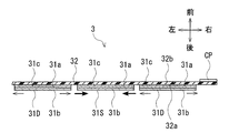
以下、図6および図7に基づいて、変形作用部73による、基材フィルム32の変形方法について詳述する。また、取付状態判定部74による、バンパーカバー22に対するセンサ素子31の取付不良判定方法について詳述する。変形作用部73は、センサ素子31の中から、荷重をかけて変形させる1又は複数の素子を選択する。そして、変形作用部73は、選択したセンサ素子31S(図6においてハッチングされた素子)が有する第1分割電極31bと第2分割電極31cとの間に、所定の駆動電圧Vipを印加する(荷重をかける)。これにより、変形作用部73は、図6に例示するように、選択したセンサ素子31Sを収縮させる。以下、「センサ素子31S」という表現は、便宜上、「変形素子31S」と表現する場合がある。
以下、図6および図7に基づいて、変形作用部73による、基材フィルム32の変形方法について詳述する。また、取付状態判定部74による、バンパーカバー22に対するセンサ素子31の取付不良判定方法について詳述する。変形作用部73は、センサ素子31の中から、荷重をかけて変形させる1又は複数の素子を選択する。そして、変形作用部73は、選択したセンサ素子31S(図6においてハッチングされた素子)が有する第1分割電極31bと第2分割電極31cとの間に、所定の駆動電圧Vipを印加する(荷重をかける)。これにより、変形作用部73は、図6に例示するように、選択したセンサ素子31Sを収縮させる。以下、「センサ素子31S」という表現は、便宜上、「変形素子31S」と表現する場合がある。
上述したように、基材フィルム32は、4つの固定部CPにおいて、バンパーカバー22に固定されている。そのため、変形素子31Sの収縮によって、基材フィルム32は、引っ張る方向に変形する。そして、基材フィルム32の変形によって、変形素子31Sに隣接した1又は複数のセンサ素子31D(検出セル)は、引っ張る方向に変形する。これにより、センサ素子31Dでは、図7に例示するように、第1分割電極31bと第2分割電極31cとの間に、所定の変形電圧Vdg(第1信号)が発生する。以下、「センサ素子31D」という表現は、便宜上、「検出素子31D(検出セル)」と表現する場合がある。なお、検出素子31Dには、変形作用部73によって、駆動電圧Vipが印加されていない(荷重がかけられていない)。また、検出素子31Dは、変形素子31Sに隣接していることが望ましい。しかし、検出素子31Dは、必ずしも変形素子31Sに隣接していなければならないわけではない。検出素子31Dは、電気ノイズから変形電圧Vdgを切り分けられる範囲において、変形素子31Sから離れた位置にあってもよい。
取付状態判定部74には、所定の規定電圧Vfxが記憶されている。例えば、基材フィルム32を介して、センサ素子31がバンパーカバー22に正常に取り付けられているとする。規定電圧Vfx(第2信号に相当)は、このような正常状態において、変形素子31Sに駆動電圧Vipを印加した場合に、検出素子31Dに発生する変形電圧Vdgである。規定電圧Vfxは、予め実施しておいた実験結果に基づき求められる。なお、上記正常状態とは、基材フィルム32がバンパーカバー22に対して正常に取り付けられており、かつ、センサ素子31が基材フィルム32に対して正常に取り付けられている状態である。規定電圧Vfxは、予め実験的に求められている。
これに対して、バンパーカバー22に対して、センサ素子31の取付不良が発生しているとする。このような不良状態では、変形素子31Sに駆動電圧Vipを印加しても、検出素子31Dに発生する変形電圧Vdgは、規定電圧Vfxとは異なる値となる。なお、上記不良状態とは、バンパーカバー22に対する基材フィルム32の剥がれ、および、基材フィルム32に対するセンサ素子31の剥がれ、のうちの少なくともいずれかに起因して発生した状態である。
例えば、バンパーカバー22から基材フィルム32が剥がれているとする。このような状態において、変形素子31Sに駆動電圧Vipが印加されたとする。その結果、基材フィルム32は、バンパーカバー22に固定されていないため、変形素子31Sの動きに合わせて移動するだけである。つまり、基材フィルム32は、変形しない。このため、検出素子31Dは、所定の変形電圧Vdg(第1信号)を発生しない。
一方、基材フィルム32から変形素子31Sが剥がれているとする。このような状態において、変形素子31Sに駆動電圧Vipが印加されたとする。その結果、変形素子31Sが剥がれているため、電圧印加による変形は、変形素子31Sから基材フィルム32に伝達されない。また、基材フィルム32から検出素子31Dが剥がれているとする。このような状態において、変形素子31Sに駆動電圧Vipが印加されたとする。その結果、検出素子31Dが剥がれているため、基材フィルム32に所定の変形が発生しても、当該変形が検出素子31Dに伝達されることはない。このため、検出素子31Dは、所定の変形電圧Vdg(第1信号)を発生しない。
取付状態判定部74は、検出素子31Dから発生した変形電圧Vdg(第1信号)と、規定電圧Vfx(第2信号)と、に基づいて、バンパーカバー22に対するセンサ素子31の取付不良の有無を判定する。具体的には、取付状態判定部74は、複数の検出素子31Dそれぞれについて、変形電圧Vdgと規定電圧Vfxとの差分(絶対値)を算出する。取付状態判定部74は、算出した差分が、判定条件の所定量であるか否かを判定する。取付状態判定部74は、複数の検出素子31Dのうち、差分が所定量である素子(差分が基準偏差より大きい素子)が、少なくとも1つでもある場合に、センサ素子31の取付不良が発生していると判定する。
一方、基材フィルム32から変形素子31Sが剥がれているとする。このような状態において、変形素子31Sに駆動電圧Vipが印加されたとする。その結果、変形素子31Sが剥がれているため、電圧印加による変形は、変形素子31Sから基材フィルム32に伝達されない。また、基材フィルム32から検出素子31Dが剥がれているとする。このような状態において、変形素子31Sに駆動電圧Vipが印加されたとする。その結果、検出素子31Dが剥がれているため、基材フィルム32に所定の変形が発生しても、当該変形が検出素子31Dに伝達されることはない。このため、検出素子31Dは、所定の変形電圧Vdg(第1信号)を発生しない。
取付状態判定部74は、検出素子31Dから発生した変形電圧Vdg(第1信号)と、規定電圧Vfx(第2信号)と、に基づいて、バンパーカバー22に対するセンサ素子31の取付不良の有無を判定する。具体的には、取付状態判定部74は、複数の検出素子31Dそれぞれについて、変形電圧Vdgと規定電圧Vfxとの差分(絶対値)を算出する。取付状態判定部74は、算出した差分が、判定条件の所定量であるか否かを判定する。取付状態判定部74は、複数の検出素子31Dのうち、差分が所定量である素子(差分が基準偏差より大きい素子)が、少なくとも1つでもある場合に、センサ素子31の取付不良が発生していると判定する。
取付状態判定部74は、センサ素子31の取付不良判定を、次のように実施してもよい。具体的には、取付不良判定では、複数のセンサ素子31の中で、変形素子31Sおよび検出素子31Dを変更する。そして、取付状態判定部74は、変形素子31Sへの駆動電圧Vipの印加と、検出素子31Dに発生する変形電圧Vdgの検出と、を順次行う。このように、取付不良判定では、素子の変更と電圧の検出とを繰り返し行ってもよい。また、取付不良判定の実施タイミングは、特に限定されない。例えば、図8に例示するように、取付不良判定は、歩行者保護システム1(車両用衝突検知装置)の制御処理が実行される度に行ってもよい。また、取付不良判定は、車両VEのイグニッションスイッチがオンされた直後に行ってもよい。取付不良判定は、イグニッションスイッチがオンされている間において、所定時間が経過する度に繰り返して行ってもよい。
(歩行者保護システムの制御方法)
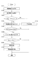
以下、図8に基づいて、歩行者保護システム1(車両用衝突検知装置)の制御方法を示す処理手順(制御処理)について説明する。本処理は、歩行者保護ECU7によって実行される。より具体的には、本処理は、歩行者保護ECU7が備える、車速判定部71、衝突判定部72、変形作用部73、取付状態判定部74、AND回路75、および保護装置ドライバー76によって実行される。
最初に、歩行者保護ECU7は、変形作用部73によって、変形素子31Sに対して、所定の駆動電圧Vipを印加する(ステップS101)。
次に、歩行者保護ECU7は、取付状態判定部74によって、検出素子31Dに発生した変形電圧Vdg(第1信号)を検出する(ステップS102)。
その後、取付状態判定部74は、複数の検出素子31Dのそれぞれについて、検出された変形電圧Vdgと規定電圧Vfxとの差分|Vdg-Vfx|を算出する。取付状態判定部74は、算出した差分が、基準偏差ε以下であるか否かを判定する(ステップS103)。このときの基準偏差εは、0に近似する所定の正値に設定されている。
その結果、取付状態判定部74は、複数の検出素子31Dのうち、少なくとも1つの素子について、差分|Vdg-Vfx|が、基準偏差εより大きいと判定した場合(ステップS103:No)、センサ素子31の取付不良が発生していると判定する。取付状態判定部74は、AND回路75にロー(L)信号を出力する。そして、取付状態判定部74は、インスツルメントパネル6を介して、バンパーカバー22に対するセンサ素子31の取付不良が発生している旨を警告する(ステップS110)。そして、歩行者保護ECU7は、本制御フローを終了する。よって、衝突検知センサ3による衝突検知は行われない。
以下、図8に基づいて、歩行者保護システム1(車両用衝突検知装置)の制御方法を示す処理手順(制御処理)について説明する。本処理は、歩行者保護ECU7によって実行される。より具体的には、本処理は、歩行者保護ECU7が備える、車速判定部71、衝突判定部72、変形作用部73、取付状態判定部74、AND回路75、および保護装置ドライバー76によって実行される。
最初に、歩行者保護ECU7は、変形作用部73によって、変形素子31Sに対して、所定の駆動電圧Vipを印加する(ステップS101)。
次に、歩行者保護ECU7は、取付状態判定部74によって、検出素子31Dに発生した変形電圧Vdg(第1信号)を検出する(ステップS102)。
その後、取付状態判定部74は、複数の検出素子31Dのそれぞれについて、検出された変形電圧Vdgと規定電圧Vfxとの差分|Vdg-Vfx|を算出する。取付状態判定部74は、算出した差分が、基準偏差ε以下であるか否かを判定する(ステップS103)。このときの基準偏差εは、0に近似する所定の正値に設定されている。
その結果、取付状態判定部74は、複数の検出素子31Dのうち、少なくとも1つの素子について、差分|Vdg-Vfx|が、基準偏差εより大きいと判定した場合(ステップS103:No)、センサ素子31の取付不良が発生していると判定する。取付状態判定部74は、AND回路75にロー(L)信号を出力する。そして、取付状態判定部74は、インスツルメントパネル6を介して、バンパーカバー22に対するセンサ素子31の取付不良が発生している旨を警告する(ステップS110)。そして、歩行者保護ECU7は、本制御フローを終了する。よって、衝突検知センサ3による衝突検知は行われない。
一方、取付状態判定部74は、すべての検出素子31Dについて、差分|Vdg-Vfx|が、基準偏差ε以下であると判定した場合(ステップS103:Yes)、センサ素子31の取付不良が発生していないと判定する。取付状態判定部74は、AND回路75にハイ(H)信号を出力する。その後、速度センサ4から車速判定部71に対して、車両VEの車速検出値Sdetが入力される(ステップS104)。
歩行者保護ECU7は、車速判定部71によって、車速検出値Sdetが、第1車速閾値Sth1から第2車速閾値Sth2までの範囲内の値(Sth1≦Sdet≦Sth2)か否かを判定する(ステップS105)。具体的には、車速判定部71は、車速検出値Sdetが、第1車速閾値Sth1以上であり、かつ、第2車速閾値Sth2以下であるか否かを判定する。
その結果、車速判定部71は、車速検出値Sdetが、第1車速閾値Sth1未満、または、第2車速閾値Sth2より大きいと判定した場合(ステップS105:No)、AND回路75にロー(L)信号を出力する。そして、歩行者保護ECU7は、本制御フローを終了する。一方、車速判定部71は、車速検出値Sdetが、第1車速閾値Sth1以上であり、かつ、第2車速閾値Sth2以下であると判定した場合(ステップS105:Yes)、AND回路75にハイ(H)信号を出力する。その後、センサ素子31から衝突判定部72に対して、ピエゾフィルム電圧Vpzが入力される(ステップS106)。
歩行者保護ECU7は、車速判定部71によって、車速検出値Sdetが、第1車速閾値Sth1から第2車速閾値Sth2までの範囲内の値(Sth1≦Sdet≦Sth2)か否かを判定する(ステップS105)。具体的には、車速判定部71は、車速検出値Sdetが、第1車速閾値Sth1以上であり、かつ、第2車速閾値Sth2以下であるか否かを判定する。
その結果、車速判定部71は、車速検出値Sdetが、第1車速閾値Sth1未満、または、第2車速閾値Sth2より大きいと判定した場合(ステップS105:No)、AND回路75にロー(L)信号を出力する。そして、歩行者保護ECU7は、本制御フローを終了する。一方、車速判定部71は、車速検出値Sdetが、第1車速閾値Sth1以上であり、かつ、第2車速閾値Sth2以下であると判定した場合(ステップS105:Yes)、AND回路75にハイ(H)信号を出力する。その後、センサ素子31から衝突判定部72に対して、ピエゾフィルム電圧Vpzが入力される(ステップS106)。
歩行者保護ECU7は、衝突判定部72によって、ピエゾフィルム電圧Vpzが、電圧閾値Vth以上であるか否かを判定する(ステップS107)。このときの電圧閾値Vthは、次のように設定されている。例えば、歩行者または自転車が、バンパーカバー22に衝突した場合に発生するピエゾフィルム電圧をVpz1とする。一方、歩行者または自転車以外の物体(地上構造物等)が、バンパーカバー22に衝突した場合に発生するピエゾフィルム電圧をVpz2とする。この場合の電圧閾値Vthは、Vpz1とVpz2との間の値に設定されている。
その結果、衝突判定部72は、ピエゾフィルム電圧Vpzが、電圧閾値Vth以上であると判定した場合(ステップS107:Yes)、保護装置5の作動を必要とする衝突が、バンパーカバー22において発生したと判定する(ステップS108)。衝突判定部72は、AND回路75にハイ(H)信号を出力する。そして、歩行者保護ECU7は、保護装置ドライバー76が、AND回路75の出力信号に基づいて、保護装置5を作動させる(ステップS109)。
一方、衝突判定部72は、ピエゾフィルム電圧Vpzが、電圧閾値Vth未満であると判定した場合(ステップS107:No)、AND回路75にロー(L)信号を出力する。そして、歩行者保護ECU7は、本制御フローを終了する。
その結果、衝突判定部72は、ピエゾフィルム電圧Vpzが、電圧閾値Vth以上であると判定した場合(ステップS107:Yes)、保護装置5の作動を必要とする衝突が、バンパーカバー22において発生したと判定する(ステップS108)。衝突判定部72は、AND回路75にハイ(H)信号を出力する。そして、歩行者保護ECU7は、保護装置ドライバー76が、AND回路75の出力信号に基づいて、保護装置5を作動させる(ステップS109)。
一方、衝突判定部72は、ピエゾフィルム電圧Vpzが、電圧閾値Vth未満であると判定した場合(ステップS107:No)、AND回路75にロー(L)信号を出力する。そして、歩行者保護ECU7は、本制御フローを終了する。
<第1実施形態の効果>
本実施形態によれば、歩行者保護システム1(車両用衝突検知装置)は、バンパーカバー22に対するセンサ素子31の取付不良の有無を判定する取付状態判定部74を備えている。取付状態判定部74は、変形作用部73によって基材フィルム32が変形された場合にセンサ素子31が発生する変形電圧Vdg(第1信号)と、基材フィルム32を介して、センサ素子31がバンパーカバー22に正常に取り付けられている場合の規定電圧Vfx(第2信号)と、に基づいて、バンパーカバー22に対するセンサ素子31の取付不良の有無を判定している。これにより、歩行者保護システム1では、基材フィルム32がバンパーカバー22から剥離したことに起因する、バンパーカバー22に対するセンサ素子31の取付不良を検出できる。または、歩行者保護システム1では、センサ素子31が基材フィルム32から剥離したことに起因する、バンパーカバー22に対するセンサ素子31の取付不良を検出できる。したがって、本実施形態では、センサ素子31の取付不良が発生した場合には、車両VEの運転者に警告するとともに、歩行者保護システム1の作動を停止できる。よって、本実施形態では、信頼性の高い歩行者保護システム1を提供できる。
本実施形態によれば、歩行者保護システム1(車両用衝突検知装置)は、バンパーカバー22に対するセンサ素子31の取付不良の有無を判定する取付状態判定部74を備えている。取付状態判定部74は、変形作用部73によって基材フィルム32が変形された場合にセンサ素子31が発生する変形電圧Vdg(第1信号)と、基材フィルム32を介して、センサ素子31がバンパーカバー22に正常に取り付けられている場合の規定電圧Vfx(第2信号)と、に基づいて、バンパーカバー22に対するセンサ素子31の取付不良の有無を判定している。これにより、歩行者保護システム1では、基材フィルム32がバンパーカバー22から剥離したことに起因する、バンパーカバー22に対するセンサ素子31の取付不良を検出できる。または、歩行者保護システム1では、センサ素子31が基材フィルム32から剥離したことに起因する、バンパーカバー22に対するセンサ素子31の取付不良を検出できる。したがって、本実施形態では、センサ素子31の取付不良が発生した場合には、車両VEの運転者に警告するとともに、歩行者保護システム1の作動を停止できる。よって、本実施形態では、信頼性の高い歩行者保護システム1を提供できる。
変形作用部73は、複数のセンサ素子31の中から、荷重をかけて変形させる変形素子31Sを選択する。そして、変形作用部73は、選択した変形素子31Sに駆動電圧Vipを印加する(荷重をかける)。これにより、変形作用部73は、変形素子31Sの収縮によって、基材フィルム32を変形させている。そして、取付状態判定部74は、駆動電圧Vipが印加されていない検出素子31Dに発生した変形電圧Vdg(第1信号)に基づいて、バンパーカバー22に対するセンサ素子31の取付不良判定を行っている。このように、歩行者保護システム1では、衝突検知をするためのセンサ素子31のみを用いて、センサ素子31の取付不良判定が行える。よって、本実施形態では、センサ素子31の取付不良判定のために、基材フィルム32を変形させる特別なアクチュエータ等を必要としない。
基材フィルム32において、取付状態判定部74によって変形電圧Vdgが検出される検出素子31Dは、変形作用部73によって駆動電圧Vipが印加された変形素子31Sに隣接している。これにより、歩行者保護システム1では、変形素子31Sの収縮による基材フィルム32の変形を容易に検出できる。よって、本実施形態では、バンパーカバー22に対するセンサ素子31の取付不良判定を精度よく実施できる。
基材フィルム32は、略矩形状をしている。基材フィルム32は、センサ素子31が接合されていない4つの固定部CPにおいて、バンパーカバー22に取り付けられている。これにより、歩行者保護システム1では、バンパーカバー22に対する基材フィルム32の取付工程を簡素化できる。また、歩行者保護システム1では、基材フィルム32において、バンパーカバー22に接合する4つの固定部CP以外の部位を変形させられる。そのため、本実施形態では、基材フィルム32において、変形素子31Sの配置可能範囲が広い。
基材フィルム32は、略矩形状をしている。基材フィルム32は、センサ素子31が接合されていない4つの固定部CPにおいて、バンパーカバー22に取り付けられている。これにより、歩行者保護システム1では、バンパーカバー22に対する基材フィルム32の取付工程を簡素化できる。また、歩行者保護システム1では、基材フィルム32において、バンパーカバー22に接合する4つの固定部CP以外の部位を変形させられる。そのため、本実施形態では、基材フィルム32において、変形素子31Sの配置可能範囲が広い。
以降、第1実施形態の変形例および他の実施形態について説明する。なお、以降では、第1実施形態と異なる事項について説明する。同一事項については、同一符号を付し、その説明を省略する。
<第1変形例>
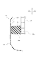
以下、図9に基づいて、第1実施形態の第1変形例に係る衝突検知センサ3のバンパーカバー22への取付方法について説明する。なお、図9には、衝突検知センサ3の左右方向の長さを実際より縮めて模式的に表している。本変形例の基材フィルム32は、第1実施形態と同様に、略矩形状をしている。基材フィルム32は、センサ素子31が接合されていない周縁固定部FPにおいて、バンパーカバー22に取り付けられている。図9に例示するように、周縁固定部FPは、上縁部、下縁部、左縁部、および右縁部を含む基材フィルム32の周縁部である。基材フィルム32は、このような周縁固定部FPにおいて、バンパーカバー22に固定されている。本変形例の衝突検知センサ3のその他の構成は、第1実施形態と同様である。そのため、これ以上の説明は省略する。
<第1変形例>
以下、図9に基づいて、第1実施形態の第1変形例に係る衝突検知センサ3のバンパーカバー22への取付方法について説明する。なお、図9には、衝突検知センサ3の左右方向の長さを実際より縮めて模式的に表している。本変形例の基材フィルム32は、第1実施形態と同様に、略矩形状をしている。基材フィルム32は、センサ素子31が接合されていない周縁固定部FPにおいて、バンパーカバー22に取り付けられている。図9に例示するように、周縁固定部FPは、上縁部、下縁部、左縁部、および右縁部を含む基材フィルム32の周縁部である。基材フィルム32は、このような周縁固定部FPにおいて、バンパーカバー22に固定されている。本変形例の衝突検知センサ3のその他の構成は、第1実施形態と同様である。そのため、これ以上の説明は省略する。
<第1変形例の効果>
本変形例によれば、基材フィルム32は、略矩形状をしている。基材フィルム32は、センサ素子31が接合されていない周縁固定部FPにおいて、バンパーカバー22に取り付けられている。これにより、歩行者保護システム1では、基材フィルム32をバンパーカバー22に強固に取り付けられる。また、歩行者保護システム1では、周縁固定部FPによって囲まれた部位のどの位置であっても基材フィルム32を変形させられる。よって、本変形例では、バンパーカバー22に対するセンサ素子31の取付不良判定が容易に行える。
本変形例によれば、基材フィルム32は、略矩形状をしている。基材フィルム32は、センサ素子31が接合されていない周縁固定部FPにおいて、バンパーカバー22に取り付けられている。これにより、歩行者保護システム1では、基材フィルム32をバンパーカバー22に強固に取り付けられる。また、歩行者保護システム1では、周縁固定部FPによって囲まれた部位のどの位置であっても基材フィルム32を変形させられる。よって、本変形例では、バンパーカバー22に対するセンサ素子31の取付不良判定が容易に行える。
<第2変形例>
以下、図10に基づいて、第1実施形態の第2変形例に係る衝突検知センサ3のバンパーカバー22への取付方法について説明する。なお、図10には、衝突検知センサ3の左右方向の長さを実際より縮めて模式的に表している。本変形例の基材フィルム32は、第1実施形態と同様に、略矩形状をしている。複数のセンサ素子31は、基材フィルム32において、縦列および横列を形成するように並べられている。
以下、図10に基づいて、第1実施形態の第2変形例に係る衝突検知センサ3のバンパーカバー22への取付方法について説明する。なお、図10には、衝突検知センサ3の左右方向の長さを実際より縮めて模式的に表している。本変形例の基材フィルム32は、第1実施形態と同様に、略矩形状をしている。複数のセンサ素子31は、基材フィルム32において、縦列および横列を形成するように並べられている。
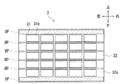
基材フィルム32は、列間固定部BPと、上下縁固定部OPと、において、バンパーカバー22に取り付けられている。列間固定部BPは、基材フィルム32において、センサ素子31の隣り合った横列同士の間に位置する部位に相当する。上下縁固定部OPは、センサ素子31が接合されていない上縁部および下縁部を含む基材フィルム32の縁部である。なお、列間固定部BPの説明の中で「部位に相当する」として説明している理由は次の通りである。センサ素子31は、基材フィルム32の一面32aに取り付けられている。これに対して、基材フィルム32は、一面32aと異なる他面32bを介して、バンパーカバー22に取り付けられている。つまり、センサ素子31の取付面とバンパーカバー22の取付面とは、基材フィルム32において同一面にないためである。また、基材フィルム32は、センサ素子31の隣り合った縦列同士の間に位置する部位において、バンパーカバー22に取り付けられていてもよい。本変形例の衝突検知センサ3のその他の構成は、第1実施形態と同様である。
そのため、これ以上の説明は省略する。
そのため、これ以上の説明は省略する。
<第2変形例の効果>
本変形例によれば、基材フィルム32は、センサ素子31の隣り合った横列同士の間に位置する列間固定部BPにおいて、バンパーカバー22に取り付けられている。これにより、歩行者保護システム1では、基材フィルム32において、バンパーカバー22への取付位置が均等に設けられる。よって、本変形例では、バンパーカバー22において発生した衝突を、衝突検知センサ3により精度よく検出できる。また、歩行者保護システム1では、変形素子31Sと検出素子31Dとを、横方向に隣り合うセンサ素子31として基材フィルム32に配置している。よって、本変形例では、変形素子31Sの収縮による基材フィルム32の変形を、検出素子31Dにより精度よく検出できる。
本変形例によれば、基材フィルム32は、センサ素子31の隣り合った横列同士の間に位置する列間固定部BPにおいて、バンパーカバー22に取り付けられている。これにより、歩行者保護システム1では、基材フィルム32において、バンパーカバー22への取付位置が均等に設けられる。よって、本変形例では、バンパーカバー22において発生した衝突を、衝突検知センサ3により精度よく検出できる。また、歩行者保護システム1では、変形素子31Sと検出素子31Dとを、横方向に隣り合うセンサ素子31として基材フィルム32に配置している。よって、本変形例では、変形素子31Sの収縮による基材フィルム32の変形を、検出素子31Dにより精度よく検出できる。
<第2実施形態>
以下、図11に基づいて、第2実施形態に係る衝突検知センサ3Aについて説明する。なお、図11には、衝突検知センサ3Aの左右方向の長さを実際より縮めて模式的に表している。本実施形態の衝突検知センサ3Aは、図11に例示するような基材フィルム32を備えている。基材フィルム32は、第1実施形態と同様に、略矩形状をしている。基材フィルム32は、センサ素子31が接合されていない4つの固定部CPにおいて、バンパーカバー22に取り付けられている。基材フィルム32には、複数のアクチュエータ金属片33(変形作用部)が形成されている。図11に例示するように、複数のアクチュエータ金属片33それぞれは、センサ素子31の隣り合った横列同士の間に配置されている。なお、図11の破線に示されるように、複数のアクチュエータ金属片33それぞれは、センサ素子31の隣り合った縦列同士の間に配置されていてもよい。
以下、図11に基づいて、第2実施形態に係る衝突検知センサ3Aについて説明する。なお、図11には、衝突検知センサ3Aの左右方向の長さを実際より縮めて模式的に表している。本実施形態の衝突検知センサ3Aは、図11に例示するような基材フィルム32を備えている。基材フィルム32は、第1実施形態と同様に、略矩形状をしている。基材フィルム32は、センサ素子31が接合されていない4つの固定部CPにおいて、バンパーカバー22に取り付けられている。基材フィルム32には、複数のアクチュエータ金属片33(変形作用部)が形成されている。図11に例示するように、複数のアクチュエータ金属片33それぞれは、センサ素子31の隣り合った横列同士の間に配置されている。なお、図11の破線に示されるように、複数のアクチュエータ金属片33それぞれは、センサ素子31の隣り合った縦列同士の間に配置されていてもよい。
複数のアクチュエータ金属片33それぞれは、例えば、形状記憶合金によって形成されている。アクチュエータ金属片33は、その全長に渡って基材フィルム32に固定されている。変形作用部73は、センサ素子31(変形素子31S)の収縮によって基材フィルム32を変形させることに代えて、アクチュエータ金属片33を用いて、基材フィルム32を変形させている。具体的には、変形作用部73は、アクチュエータ金属片33に電流を流し発熱させる。その結果、アクチュエータ金属片33は変形する。これにより、変形作用部73は、アクチュエータ金属片33が配置されている基材フィルム32を変形させている。変形作用部73によって、アクチュエータ金属片33に電流が流された場合に、取付状態判定部74は、いずれかのセンサ素子31(検出素子31D)に発生した変形電圧Vdg(第1信号)を検出する。取付状態判定部74は、変形電圧Vdgに基づいて、バンパーカバー22に対するセンサ素子31の取付不良の有無を判定する。なお、本実施形態では、アクチュエータ金属片33それぞれが、センサ素子31の隣り合った縦列同士の間に配置されていても、上述した場合と同様に機能する。本実施形態のその他の構成は、第1実施形態と同様である。また、本実施形態に係るセンサ素子31の取付不良判定の方法は、第1実施形態と同様である。そのため、これ以上の説明は省略する。
<第2実施形態の効果>
本実施形態によれば、変形作用部73は、基材フィルム32に設けられたアクチュエータ金属片33に電流を流し発熱させる。その結果、アクチュエータ金属片33は変形する。このように、変形作用部73は、アクチュエータ金属片33の変形によって、基材フィルム32を変形させている。その結果、基材フィルム32に配置されたセンサ素子31は、第1実施形態の構成に比べて大きく変形する。これにより、本実施形態では、電気ノイズからの変形電圧Vdgの切り分けを容易にできる。したがって、本実施形態では、センサ素子31の取付不良判定を精度よく行え、より信頼性の高い歩行者保護システム1を提供できる。また、本実施形態では、基材フィルム32を変形させるために、センサ素子31を用いる必要がない。そのため、本実施形態では、取付不良判定が、センサ素子31の機能に影響を与えることがない。アクチュエータ金属片33それぞれは、センサ素子31の隣り合った横列同士の間に配置されている。これにより、本実施形態では、基材フィルム32における、センサ素子31の配置および形状に影響を与えることがない。
本実施形態によれば、変形作用部73は、基材フィルム32に設けられたアクチュエータ金属片33に電流を流し発熱させる。その結果、アクチュエータ金属片33は変形する。このように、変形作用部73は、アクチュエータ金属片33の変形によって、基材フィルム32を変形させている。その結果、基材フィルム32に配置されたセンサ素子31は、第1実施形態の構成に比べて大きく変形する。これにより、本実施形態では、電気ノイズからの変形電圧Vdgの切り分けを容易にできる。したがって、本実施形態では、センサ素子31の取付不良判定を精度よく行え、より信頼性の高い歩行者保護システム1を提供できる。また、本実施形態では、基材フィルム32を変形させるために、センサ素子31を用いる必要がない。そのため、本実施形態では、取付不良判定が、センサ素子31の機能に影響を与えることがない。アクチュエータ金属片33それぞれは、センサ素子31の隣り合った横列同士の間に配置されている。これにより、本実施形態では、基材フィルム32における、センサ素子31の配置および形状に影響を与えることがない。
<第3実施形態>
以下、図12および図13に基づいて、第3実施形態に係る衝突検知センサ3Bについて説明する。なお、図12には、衝突検知センサ3Bの左右方向の長さを実際より縮めて模式的に表している。本実施形態の衝突検知センサ3Bは、図12に例示するように、センサ素子34(衝突センサ)と、基材フィルム32と、を備えている。本実施形態のセンサ素子34は、第1実施形態とは異なり、複数に分割されていない。センサ素子34は、一体に形成されている。図13に例示するように、センサ素子34は、圧電性高分子フィルム34a(圧電フィルム)と、第1および第2電極34b,34cと、を有している。第1および第2電極34b,34cは、平板状に形成されている。第1および第2電極34b,34cは、圧電性高分子フィルム34aの両面を挟むように形成されている。第1および第2電極34b,34cは、一対の電極に該当する。センサ素子34は、当該素子の変形量に応じて、第1電極34bと第2電極34cとの間に、ピエゾフィルム電圧Vpz(所定の出力電圧)を発生する。
以下、図12および図13に基づいて、第3実施形態に係る衝突検知センサ3Bについて説明する。なお、図12には、衝突検知センサ3Bの左右方向の長さを実際より縮めて模式的に表している。本実施形態の衝突検知センサ3Bは、図12に例示するように、センサ素子34(衝突センサ)と、基材フィルム32と、を備えている。本実施形態のセンサ素子34は、第1実施形態とは異なり、複数に分割されていない。センサ素子34は、一体に形成されている。図13に例示するように、センサ素子34は、圧電性高分子フィルム34a(圧電フィルム)と、第1および第2電極34b,34cと、を有している。第1および第2電極34b,34cは、平板状に形成されている。第1および第2電極34b,34cは、圧電性高分子フィルム34aの両面を挟むように形成されている。第1および第2電極34b,34cは、一対の電極に該当する。センサ素子34は、当該素子の変形量に応じて、第1電極34bと第2電極34cとの間に、ピエゾフィルム電圧Vpz(所定の出力電圧)を発生する。
第1実施形態と同様に、基材フィルム32の一面32aは、圧電性高分子フィルム34aに取り付けられていない、第2電極34cの面に接合されている。そして、各センサ素子34は、例えば、接着剤または両面接着テープによって基材フィルム32に接合されている。一方、基材フィルム32の他面32bは、バンパーカバー22の裏面22aに取り付けられている。また、基材フィルム32は、略矩形状をしている。基材フィルム32は、センサ素子34が接合されていない4つの固定部CPにおいて、バンパーカバー22に取り付けられている。
本実施形態では、基材フィルム32において、上縁部に形成された上端部入力点UP、および、右側部に形成された側端部入力点SPにはそれぞれ、変形作用装置35(変形作用部による制御対象装置)が接続されている。上端部入力点UPおよび側端部入力点SPは、4つの固定部CPとは異なる位置に形成されている。変形作用装置35は、例えば、電磁アクチュエータまたは静電アクチュエータによって構成されている。なお、変形作用装置35は、例えば、圧電素子または形状記憶合金によって形成されていてもよい。変形作用部73は、センサ素子31の収縮によって基材フィルム32を変形させることに代えて、変形作用装置35を用いて、基材フィルム32を変形させている。変形作用部73は、変形作用装置35を作動させる。その結果、変形作用装置35は、基材フィルム32の上端部入力点UPを上方に牽引する。または、変形作用装置35は、側端部入力点SPを右方に牽引する。
変形作用装置35によって、基材フィルム32が牽引された場合に、取付状態判定部74は、センサ素子34に発生した変形電圧Vdg(第1信号)を検出する。取付状態判定部74は、変形電圧Vdgに基づいて、バンパーカバー22に対するセンサ素子34の取付不良の有無を判定する。なお、変形作用装置35は、上端部入力点UPおよび側端部入力点SPの両方に接続されている必要はない。変形作用装置35は、上端部入力点UPおよび側端部入力点SPのうち、いずれか一方に接続されていればよい。また、変形作用装置35は、基材フィルム32の下縁部または左側部に接続されていてもよい。さらに、センサ素子34は、第1実施形態と同様に、複数のセンサ素子31に分割されていてもよい。本実施形態のその他の構成は、第1実施形態と同様である。また、本実施形態に係るセンサ素子31の取付不良判定の方法は、第1実施形態と同様である。そのため、これ以上の説明は省略する。
<他の実施形態>
本開示の技術は、上述した実施形態に限定されない。本開示の技術は、次のように変形または拡張できる。
例えば、歩行者保護システム1では、バンパーカバー22に対するセンサ素子31の取付不良の有無を判定する場合、必ずしも基材フィルム32を引っ張る方向に変形させなければならないわけではない。歩行者保護システム1では、基材フィルム32を縮む方向に変形させ、変形に伴って発生した変形電圧Vdgを検出し、センサ素子31の取付不良の有無を判定するようにしてもよい。
また、歩行者保護システム1では、第2実施形態において、基材フィルム32の周縁部に、アクチュエータ金属片33を取り付ける。そして、歩行者保護システム1では、第3実施形態と同様に一体に形成されたセンサ素子34を、基材フィルム32に接合してもよい。
本開示の技術は、上述した実施形態に限定されない。本開示の技術は、次のように変形または拡張できる。
例えば、歩行者保護システム1では、バンパーカバー22に対するセンサ素子31の取付不良の有無を判定する場合、必ずしも基材フィルム32を引っ張る方向に変形させなければならないわけではない。歩行者保護システム1では、基材フィルム32を縮む方向に変形させ、変形に伴って発生した変形電圧Vdgを検出し、センサ素子31の取付不良の有無を判定するようにしてもよい。
また、歩行者保護システム1では、第2実施形態において、基材フィルム32の周縁部に、アクチュエータ金属片33を取り付ける。そして、歩行者保護システム1では、第3実施形態と同様に一体に形成されたセンサ素子34を、基材フィルム32に接合してもよい。
1: 歩行者保護システム(車両用衝突検知装置)
5: 保護装置(歩行者保護装置)
22: バンパーカバー
31: センサ素子(衝突センサおよびセンサセル)
31a: 圧電性高分子フィルム(圧電フィルムおよび分割圧電フィルム)
31b: 第1分割電極(電極および分割電極)
31c: 第2分割電極(電極および分割電極)
31D: 検出素子(検出セル)
31S: 変形素子
32: 基材フィルム
33: アクチュエータ金属片(形状記憶合金)
34: センサ素子(衝突センサ)
34a: 圧電性高分子フィルム(圧電フィルム)
34b: 第1電極(電極)
34c: 第2電極(電極)
35: 変形作用装置
72: 衝突判定部
73: 変形作用部
74: 取付状態判定部
VE: 車両
5: 保護装置(歩行者保護装置)
22: バンパーカバー
31: センサ素子(衝突センサおよびセンサセル)
31a: 圧電性高分子フィルム(圧電フィルムおよび分割圧電フィルム)
31b: 第1分割電極(電極および分割電極)
31c: 第2分割電極(電極および分割電極)
31D: 検出素子(検出セル)
31S: 変形素子
32: 基材フィルム
33: アクチュエータ金属片(形状記憶合金)
34: センサ素子(衝突センサ)
34a: 圧電性高分子フィルム(圧電フィルム)
34b: 第1電極(電極)
34c: 第2電極(電極)
35: 変形作用装置
72: 衝突判定部
73: 変形作用部
74: 取付状態判定部
VE: 車両
Claims (8)
- 圧電フィルム(31a,34a)および該圧電フィルムの両面を挟む一対の平板状の電極(31b,31c,34b,34c)を含み、衝突による変形に応じて、前記電極の間に所定の出力信号(Vpz)を発生する衝突センサ(31,34)と、
前記衝突センサと、車両(VE)のバンパーカバー(22)の内側面(22a)と、の間に介装された基材フィルム(32)と、
前記衝突センサによって生成された前記出力信号に基づき、衝突物を保護する保護装置(5)の作動を必要とする衝突が、前記バンパーカバーにおいて発生したか否かを判定する衝突判定部(72)と、
を備える車両用衝突検知装置(1)であって、
前記バンパーカバーに接合されていない前記基材フィルムの部位(UP,SP)に対して荷重をかけ、前記基材フィルムを変形させる変形作用部(33,35,73)と、
前記変形作用部によって前記基材フィルムが変形された場合に前記衝突センサが発生する前記出力信号である第1信号(Vdg)と、前記基材フィルムを介して、前記衝突センサが前記バンパーカバー22に正常に取り付けられている場合に前記衝突センサが発生する前記出力信号である第2信号(Vfx)と、に基づいて、前記バンパーカバーに対する前記衝突センサの取付不良の有無を判定する取付状態判定部(74)と、
を備える、車両用衝突検知装置。 - 前記衝突センサは、
分割圧電フィルム(31a)と、該分割圧電フィルムの両面を挟む一対の分割電極(31b,31c)と、を有する、複数のセンサセル(31)によって構成されており、
前記基材フィルムは、
それぞれの前記センサセルに含まれる一方の前記分割電極に接合されることによって、複数の前記センサセルを隣接した素子同士が互いに離れた状態で保持しており、
前記変形作用部は、
いずれかの前記センサセルに含まれる前記分割電極に電圧を印加して、当該センサセルを用いて前記基材フィルムを変形させ、
前記取付状態判定部は、
前記変形作用部によって電圧が印加されていない前記センサセルである検出セル(31D)に発生した前記第1信号と、前記基材フィルムを介して、前記センサセルが前記バンパーカバーに正常に取り付けられている場合に前記検出セルに発生した前記第2信号と、に基づいて、前記バンパーカバーに対する前記衝突センサの取付不良の有無を判定する、請求項1に記載の車両用衝突検知装置。 - 前記検出セルは、前記変形作用部によって電圧が印加された前記センサセルに隣接している、請求項2に記載の車両用衝突検知装置。
- 複数の前記センサセルは、
前記基材フィルムにおいて、縦列および横列を形成するように並べられており、
前記基材フィルムは、
前記センサセルの隣り合った前記縦列同士の間、および、前記センサセルの隣り合った前記横列同士の間(BP)の、どちらか一方に該当する位置において、前記バンパーカバーに取り付けられている、請求項2又は3に記載の車両用衝突検知装置。 - 前記変形作用部は、
前記基材フィルムに取り付けられた形状記憶合金(33)を含み、
前記形状記憶合金に電流を流し発熱させ、前記形状記憶合金とともに前記基材フィルムを変形させる、請求項1に記載の車両用衝突検知装置。 - 前記衝突センサは、
分割圧電フィルム(31a)と、該分割圧電フィルムの両面を挟む一対の分割電極(31b,31c)と、有する、複数のセンサセル(31)によって構成されており、
前記基材フィルムは、
それぞれの前記センサセルに含まれる一方の前記分割電極に接合されることによって、複数の前記センサセルが縦列および横列を形成するように並べられるとともに、隣接した素子同士が互いに離れるように前記センサセルを保持しており、
前記形状記憶合金は、
前記センサセルの隣り合った前記縦列同士の間、または、前記センサセルの隣り合った前記横列同士の間に配置されており、
前記取付状態判定部は、
前記形状記憶合金に電流を流した場合に、前記センサセルのうちのいずれかに発生した前記第1信号と、前記基材フィルムを介して、前記センサセルが前記バンパーカバーに正常に取り付けられている場合に前記センサセルに発生した前記第2信号と、に基づいて、前記バンパーカバーに対する前記衝突センサの取付不良の有無を判定する、請求項5に記載の車両用衝突検知装置。 - 前記基材フィルムは、矩形状をしており、4つの固定部(CP)が前記バンパーカバーに取り付けられている、請求項1乃至6のいずれか一項に記載の車両用衝突検知装置。
- 前記基材フィルムは、矩形状をしており、周縁部(FP)が前記バンパーカバーに取り付けられている、請求項1乃至6のいずれか一項に記載の車両用衝突検知装置。
Priority Applications (1)
| Application Number | Priority Date | Filing Date | Title |
|---|---|---|---|
| DE112017003236.9T DE112017003236T5 (de) | 2016-06-28 | 2017-06-20 | Fahrzeugkollisionserfassungsvorrichtung |
Applications Claiming Priority (2)
| Application Number | Priority Date | Filing Date | Title |
|---|---|---|---|
| JP2016127998A JP6515881B2 (ja) | 2016-06-28 | 2016-06-28 | 車両用衝突検知装置 |
| JP2016-127998 | 2016-06-28 |
Publications (1)
| Publication Number | Publication Date |
|---|---|
| WO2018003592A1 true WO2018003592A1 (ja) | 2018-01-04 |
Family
ID=60785355
Family Applications (1)
| Application Number | Title | Priority Date | Filing Date |
|---|---|---|---|
| PCT/JP2017/022629 Ceased WO2018003592A1 (ja) | 2016-06-28 | 2017-06-20 | 車両用衝突検知装置 |
Country Status (3)
| Country | Link |
|---|---|
| JP (1) | JP6515881B2 (ja) |
| DE (1) | DE112017003236T5 (ja) |
| WO (1) | WO2018003592A1 (ja) |
Cited By (2)
| Publication number | Priority date | Publication date | Assignee | Title |
|---|---|---|---|---|
| WO2020011314A3 (de) * | 2018-07-09 | 2020-03-05 | Conti Temic Microelectronic Gmbh | Stereokameravorrichtung sowie verfahren zum betrieb der stereokameravorrichtung |
| US20240174197A1 (en) * | 2022-11-30 | 2024-05-30 | Purdue Research Foundation | Flexible piezoelectric composite films, flexible piezoelectric impact sensors, pedestrian protection systems, and related methods |
Families Citing this family (3)
| Publication number | Priority date | Publication date | Assignee | Title |
|---|---|---|---|---|
| JP7207176B2 (ja) * | 2019-05-31 | 2023-01-18 | 株式会社Soken | 衝突検知センサ、車載センサ、および車載システム |
| JP7526609B2 (ja) * | 2020-08-07 | 2024-08-01 | アルプスアルパイン株式会社 | 傷検知装置 |
| US20240241000A1 (en) * | 2020-11-23 | 2024-07-18 | Mechavision Inc. | Contact sensor with failure detection mechanism |
Citations (5)
| Publication number | Priority date | Publication date | Assignee | Title |
|---|---|---|---|---|
| JP2000346672A (ja) * | 1999-06-03 | 2000-12-15 | Nippon Signal Co Ltd:The | 物体接触検知装置 |
| JP2006117108A (ja) * | 2004-10-21 | 2006-05-11 | Denso Corp | 車両用衝突物体判別装置 |
| JP2009035251A (ja) * | 2007-07-31 | 2009-02-19 | Micronas Gmbh | 自動車内の安全装置のための作動装置 |
| JP2009051298A (ja) * | 2007-08-24 | 2009-03-12 | Honda Motor Co Ltd | 車両の衝突判定装置 |
| JP2009190732A (ja) * | 2009-05-25 | 2009-08-27 | Honda Motor Co Ltd | 車両用衝突検出装置 |
Family Cites Families (4)
| Publication number | Priority date | Publication date | Assignee | Title |
|---|---|---|---|---|
| JP2004096980A (ja) | 2002-08-30 | 2004-03-25 | Yoshihisa Osawa | 携帯用歩行発電装置 |
| JP5135757B2 (ja) | 2006-01-13 | 2013-02-06 | 日産自動車株式会社 | 導電性高分子からなる布帛を用いたセンサ、アクチュエータ |
| JP4726650B2 (ja) | 2006-02-24 | 2011-07-20 | 本田技研工業株式会社 | 車両用センサモジュール |
| JP5652352B2 (ja) | 2011-07-27 | 2015-01-14 | 株式会社デンソー | 車載用センサ |
-
2016
- 2016-06-28 JP JP2016127998A patent/JP6515881B2/ja not_active Expired - Fee Related
-
2017
- 2017-06-20 DE DE112017003236.9T patent/DE112017003236T5/de not_active Withdrawn
- 2017-06-20 WO PCT/JP2017/022629 patent/WO2018003592A1/ja not_active Ceased
Patent Citations (5)
| Publication number | Priority date | Publication date | Assignee | Title |
|---|---|---|---|---|
| JP2000346672A (ja) * | 1999-06-03 | 2000-12-15 | Nippon Signal Co Ltd:The | 物体接触検知装置 |
| JP2006117108A (ja) * | 2004-10-21 | 2006-05-11 | Denso Corp | 車両用衝突物体判別装置 |
| JP2009035251A (ja) * | 2007-07-31 | 2009-02-19 | Micronas Gmbh | 自動車内の安全装置のための作動装置 |
| JP2009051298A (ja) * | 2007-08-24 | 2009-03-12 | Honda Motor Co Ltd | 車両の衝突判定装置 |
| JP2009190732A (ja) * | 2009-05-25 | 2009-08-27 | Honda Motor Co Ltd | 車両用衝突検出装置 |
Cited By (4)
| Publication number | Priority date | Publication date | Assignee | Title |
|---|---|---|---|---|
| WO2020011314A3 (de) * | 2018-07-09 | 2020-03-05 | Conti Temic Microelectronic Gmbh | Stereokameravorrichtung sowie verfahren zum betrieb der stereokameravorrichtung |
| CN112136323A (zh) * | 2018-07-09 | 2020-12-25 | 康蒂-特米克微电子有限公司 | 立体摄像机装置以及运行立体摄像机装置的方法 |
| US20240174197A1 (en) * | 2022-11-30 | 2024-05-30 | Purdue Research Foundation | Flexible piezoelectric composite films, flexible piezoelectric impact sensors, pedestrian protection systems, and related methods |
| US12534043B2 (en) * | 2022-11-30 | 2026-01-27 | Purdue Research Foundation | Flexible piezoelectric composite films, flexible piezoelectric impact sensors, pedestrian protection systems, and related methods |
Also Published As
| Publication number | Publication date |
|---|---|
| JP6515881B2 (ja) | 2019-05-22 |
| DE112017003236T5 (de) | 2019-03-21 |
| JP2018001835A (ja) | 2018-01-11 |
Similar Documents
| Publication | Publication Date | Title |
|---|---|---|
| WO2018003592A1 (ja) | 車両用衝突検知装置 | |
| JP6369415B2 (ja) | 車両用衝突センサおよびそれを使用した車両用衝突検知装置 | |
| US8186471B2 (en) | Control apparatus and control method for high voltage power supply circuit and vehicle provided with control apparatus | |
| JP5104715B2 (ja) | 車両用衝突検知装置 | |
| JP5886949B2 (ja) | 乗員保護手段を起動させるための装置および方法、起動システム並びに車両 | |
| JP2002542111A (ja) | 乗物操縦者位置センサと、ホーンスイッチを備えたエアバッグカバー | |
| JP2009035251A (ja) | 自動車内の安全装置のための作動装置 | |
| JP4830475B2 (ja) | 車両用衝突荷重測定装置及びそれを用いた車両用衝突体判定装置 | |
| JP4890589B2 (ja) | 車両用衝突検出装置 | |
| JP2008107232A (ja) | 衝突検知手段 | |
| JP6406079B2 (ja) | 車両用衝突検知装置 | |
| JP2015529174A (ja) | エアバッグセンサーモジュール及びエアバッグセンサーモジュールが統合された車体 | |
| JP6376031B2 (ja) | 車両用衝突検知装置 | |
| JP4485962B2 (ja) | 車両用衝突センサ | |
| JP7140047B2 (ja) | 衝突センサ | |
| JP2018119810A (ja) | 車両用衝突センサ及びその取付構造 | |
| JP4083665B2 (ja) | 車両用衝突検出装置 | |
| WO2017006560A1 (ja) | 車両用衝突センサおよびそれを使用した車両用衝突検知装置 | |
| JP5429571B2 (ja) | 車両用衝突検知装置 | |
| JP2018114849A (ja) | 車両用衝突検知装置 | |
| JP6640016B2 (ja) | 車両用衝突検知装置 | |
| JP2010274699A (ja) | 衝突判定装置 | |
| JP2005147991A (ja) | 車両用衝突検出センサ | |
| JP6856053B2 (ja) | 衝突検知装置 | |
| JP2006168514A (ja) | 乗員保護装置の作動制御方法 |
Legal Events
| Date | Code | Title | Description |
|---|---|---|---|
| 121 | Ep: the epo has been informed by wipo that ep was designated in this application |
Ref document number: 17819951 Country of ref document: EP Kind code of ref document: A1 |
|
| 122 | Ep: pct application non-entry in european phase |
Ref document number: 17819951 Country of ref document: EP Kind code of ref document: A1 |