WO2018003568A1 - Dispositif de transmission de puissance - Google Patents
Dispositif de transmission de puissance Download PDFInfo
- Publication number
- WO2018003568A1 WO2018003568A1 PCT/JP2017/022515 JP2017022515W WO2018003568A1 WO 2018003568 A1 WO2018003568 A1 WO 2018003568A1 JP 2017022515 W JP2017022515 W JP 2017022515W WO 2018003568 A1 WO2018003568 A1 WO 2018003568A1
- Authority
- WO
- WIPO (PCT)
- Prior art keywords
- coil
- power
- power transmission
- frequency
- value
- Prior art date
Links
Images

Classifications
-
- H—ELECTRICITY
- H02—GENERATION; CONVERSION OR DISTRIBUTION OF ELECTRIC POWER
- H02J—CIRCUIT ARRANGEMENTS OR SYSTEMS FOR SUPPLYING OR DISTRIBUTING ELECTRIC POWER; SYSTEMS FOR STORING ELECTRIC ENERGY
- H02J50/00—Circuit arrangements or systems for wireless supply or distribution of electric power
- H02J50/10—Circuit arrangements or systems for wireless supply or distribution of electric power using inductive coupling
- H02J50/12—Circuit arrangements or systems for wireless supply or distribution of electric power using inductive coupling of the resonant type
-
- B—PERFORMING OPERATIONS; TRANSPORTING
- B60—VEHICLES IN GENERAL
- B60L—PROPULSION OF ELECTRICALLY-PROPELLED VEHICLES; SUPPLYING ELECTRIC POWER FOR AUXILIARY EQUIPMENT OF ELECTRICALLY-PROPELLED VEHICLES; ELECTRODYNAMIC BRAKE SYSTEMS FOR VEHICLES IN GENERAL; MAGNETIC SUSPENSION OR LEVITATION FOR VEHICLES; MONITORING OPERATING VARIABLES OF ELECTRICALLY-PROPELLED VEHICLES; ELECTRIC SAFETY DEVICES FOR ELECTRICALLY-PROPELLED VEHICLES
- B60L53/00—Methods of charging batteries, specially adapted for electric vehicles; Charging stations or on-board charging equipment therefor; Exchange of energy storage elements in electric vehicles
- B60L53/10—Methods of charging batteries, specially adapted for electric vehicles; Charging stations or on-board charging equipment therefor; Exchange of energy storage elements in electric vehicles characterised by the energy transfer between the charging station and the vehicle
- B60L53/12—Inductive energy transfer
-
- B—PERFORMING OPERATIONS; TRANSPORTING
- B60—VEHICLES IN GENERAL
- B60L—PROPULSION OF ELECTRICALLY-PROPELLED VEHICLES; SUPPLYING ELECTRIC POWER FOR AUXILIARY EQUIPMENT OF ELECTRICALLY-PROPELLED VEHICLES; ELECTRODYNAMIC BRAKE SYSTEMS FOR VEHICLES IN GENERAL; MAGNETIC SUSPENSION OR LEVITATION FOR VEHICLES; MONITORING OPERATING VARIABLES OF ELECTRICALLY-PROPELLED VEHICLES; ELECTRIC SAFETY DEVICES FOR ELECTRICALLY-PROPELLED VEHICLES
- B60L53/00—Methods of charging batteries, specially adapted for electric vehicles; Charging stations or on-board charging equipment therefor; Exchange of energy storage elements in electric vehicles
- B60L53/30—Constructional details of charging stations
- B60L53/31—Charging columns specially adapted for electric vehicles
-
- H—ELECTRICITY
- H01—ELECTRIC ELEMENTS
- H01F—MAGNETS; INDUCTANCES; TRANSFORMERS; SELECTION OF MATERIALS FOR THEIR MAGNETIC PROPERTIES
- H01F38/00—Adaptations of transformers or inductances for specific applications or functions
- H01F38/14—Inductive couplings
-
- B—PERFORMING OPERATIONS; TRANSPORTING
- B60—VEHICLES IN GENERAL
- B60L—PROPULSION OF ELECTRICALLY-PROPELLED VEHICLES; SUPPLYING ELECTRIC POWER FOR AUXILIARY EQUIPMENT OF ELECTRICALLY-PROPELLED VEHICLES; ELECTRODYNAMIC BRAKE SYSTEMS FOR VEHICLES IN GENERAL; MAGNETIC SUSPENSION OR LEVITATION FOR VEHICLES; MONITORING OPERATING VARIABLES OF ELECTRICALLY-PROPELLED VEHICLES; ELECTRIC SAFETY DEVICES FOR ELECTRICALLY-PROPELLED VEHICLES
- B60L2200/00—Type of vehicles
- B60L2200/32—Waterborne vessels
-
- B—PERFORMING OPERATIONS; TRANSPORTING
- B63—SHIPS OR OTHER WATERBORNE VESSELS; RELATED EQUIPMENT
- B63C—LAUNCHING, HAULING-OUT, OR DRY-DOCKING OF VESSELS; LIFE-SAVING IN WATER; EQUIPMENT FOR DWELLING OR WORKING UNDER WATER; MEANS FOR SALVAGING OR SEARCHING FOR UNDERWATER OBJECTS
- B63C11/00—Equipment for dwelling or working underwater; Means for searching for underwater objects
-
- H—ELECTRICITY
- H02—GENERATION; CONVERSION OR DISTRIBUTION OF ELECTRIC POWER
- H02J—CIRCUIT ARRANGEMENTS OR SYSTEMS FOR SUPPLYING OR DISTRIBUTING ELECTRIC POWER; SYSTEMS FOR STORING ELECTRIC ENERGY
- H02J50/00—Circuit arrangements or systems for wireless supply or distribution of electric power
- H02J50/80—Circuit arrangements or systems for wireless supply or distribution of electric power involving the exchange of data, concerning supply or distribution of electric power, between transmitting devices and receiving devices
-
- H—ELECTRICITY
- H02—GENERATION; CONVERSION OR DISTRIBUTION OF ELECTRIC POWER
- H02J—CIRCUIT ARRANGEMENTS OR SYSTEMS FOR SUPPLYING OR DISTRIBUTING ELECTRIC POWER; SYSTEMS FOR STORING ELECTRIC ENERGY
- H02J7/00—Circuit arrangements for charging or depolarising batteries or for supplying loads from batteries
- H02J7/00032—Circuit arrangements for charging or depolarising batteries or for supplying loads from batteries characterised by data exchange
- H02J7/00034—Charger exchanging data with an electronic device, i.e. telephone, whose internal battery is under charge
-
- Y—GENERAL TAGGING OF NEW TECHNOLOGICAL DEVELOPMENTS; GENERAL TAGGING OF CROSS-SECTIONAL TECHNOLOGIES SPANNING OVER SEVERAL SECTIONS OF THE IPC; TECHNICAL SUBJECTS COVERED BY FORMER USPC CROSS-REFERENCE ART COLLECTIONS [XRACs] AND DIGESTS
- Y02—TECHNOLOGIES OR APPLICATIONS FOR MITIGATION OR ADAPTATION AGAINST CLIMATE CHANGE
- Y02T—CLIMATE CHANGE MITIGATION TECHNOLOGIES RELATED TO TRANSPORTATION
- Y02T10/00—Road transport of goods or passengers
- Y02T10/60—Other road transportation technologies with climate change mitigation effect
- Y02T10/70—Energy storage systems for electromobility, e.g. batteries
-
- Y—GENERAL TAGGING OF NEW TECHNOLOGICAL DEVELOPMENTS; GENERAL TAGGING OF CROSS-SECTIONAL TECHNOLOGIES SPANNING OVER SEVERAL SECTIONS OF THE IPC; TECHNICAL SUBJECTS COVERED BY FORMER USPC CROSS-REFERENCE ART COLLECTIONS [XRACs] AND DIGESTS
- Y02—TECHNOLOGIES OR APPLICATIONS FOR MITIGATION OR ADAPTATION AGAINST CLIMATE CHANGE
- Y02T—CLIMATE CHANGE MITIGATION TECHNOLOGIES RELATED TO TRANSPORTATION
- Y02T10/00—Road transport of goods or passengers
- Y02T10/60—Other road transportation technologies with climate change mitigation effect
- Y02T10/7072—Electromobility specific charging systems or methods for batteries, ultracapacitors, supercapacitors or double-layer capacitors
-
- Y—GENERAL TAGGING OF NEW TECHNOLOGICAL DEVELOPMENTS; GENERAL TAGGING OF CROSS-SECTIONAL TECHNOLOGIES SPANNING OVER SEVERAL SECTIONS OF THE IPC; TECHNICAL SUBJECTS COVERED BY FORMER USPC CROSS-REFERENCE ART COLLECTIONS [XRACs] AND DIGESTS
- Y02—TECHNOLOGIES OR APPLICATIONS FOR MITIGATION OR ADAPTATION AGAINST CLIMATE CHANGE
- Y02T—CLIMATE CHANGE MITIGATION TECHNOLOGIES RELATED TO TRANSPORTATION
- Y02T90/00—Enabling technologies or technologies with a potential or indirect contribution to GHG emissions mitigation
- Y02T90/10—Technologies relating to charging of electric vehicles
- Y02T90/12—Electric charging stations
-
- Y—GENERAL TAGGING OF NEW TECHNOLOGICAL DEVELOPMENTS; GENERAL TAGGING OF CROSS-SECTIONAL TECHNOLOGIES SPANNING OVER SEVERAL SECTIONS OF THE IPC; TECHNICAL SUBJECTS COVERED BY FORMER USPC CROSS-REFERENCE ART COLLECTIONS [XRACs] AND DIGESTS
- Y02—TECHNOLOGIES OR APPLICATIONS FOR MITIGATION OR ADAPTATION AGAINST CLIMATE CHANGE
- Y02T—CLIMATE CHANGE MITIGATION TECHNOLOGIES RELATED TO TRANSPORTATION
- Y02T90/00—Enabling technologies or technologies with a potential or indirect contribution to GHG emissions mitigation
- Y02T90/10—Technologies relating to charging of electric vehicles
- Y02T90/14—Plug-in electric vehicles
Definitions
- the present disclosure relates to a power transmission device that wirelessly transmits power in water.
- an underwater base station as a power transmission device transmits power in a contactless manner with an underwater vehicle as a power receiving device using a magnetic resonance method (see, for example, Patent Document 1).
- the power transmission device includes a power transmission resonance coil, a balloon, and a balloon control mechanism.
- the power transmission resonance coil transmits power in a non-contact manner to the power reception resonance coil of the power receiving device by a magnetic field resonance method.
- the balloon contains a power transmission resonance coil.
- the balloon control mechanism removes water between the power transmission resonance coil and the power reception resonance coil by expanding the balloon during power transmission.
- an antenna device that transmits power and data to an IC-mounted medium using an electromagnetic induction method using a frequency of 13.56 MHz band is known (see, for example, Patent Document 2).
- This antenna apparatus has at least one feeding loop antenna to which a signal current is fed and at least one parasitic loop antenna to which no signal current is fed, and uses the magnetic field generated by the feeding loop antenna as a parasitic loop antenna. Also discloses that a signal current is generated and the communication range of the feed loop antenna is expanded.
- a Q factor Quality factor
- a plurality of coils including at least a power transmission resonance coil and a power reception resonance coil are used for power transmission by the magnetic field resonance method.
- the plurality of coils may have different characteristics (coil characteristics) such as size, material, length, and number of turns.
- the Q value of the coil varies depending on the coil characteristics. For this reason, if a frequency at which a Q value that matches the coil characteristics of one coil is set as a frequency (transmission frequency) used for power transmission, the transmission efficiency of power transmission may be reduced.
- This disclosure has been made in view of the above circumstances, and provides a power transmission device that can improve the transmission efficiency of non-contact power transmission to a power receiving device in water.
- the power transmission device of the present disclosure transmits power to a power reception device having a power reception coil in water.
- a power transmission device includes a power transmission coil that transmits power to a power reception coil via a magnetic field, a power transmission unit that transmits AC power of a predetermined frequency to the power transmission coil, and a resonance circuit that is connected to the power transmission coil and resonates with the power transmission coil.
- a first capacitor that forms The predetermined frequency is the first frequency at which the geometric mean value of the Q value of the power transmission coil and the Q value of the power reception coil is maximized, and the second frequency at which the Q value of the power transmission coil and the Q value of the power reception coil are the same value. Any frequency between.
- Schematic diagram showing an example of a simulation model used for the second simulation 6 is a graph showing an example of the frequency characteristic of the Q value of each coil when the simulation model of FIG. 6 is used.
- the graph which shows an example of the frequency characteristic of the Q value of the coil for every medium in which a coil is arranged Schematic diagram showing an example of an environment where a power transmission system provided with a reflection coil is placed
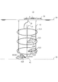
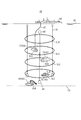
- FIG. 1 is a schematic diagram illustrating an example of an environment in which the power transmission system 10 according to the first embodiment is placed.
- the power transmission system 10 includes a power transmission device 100, a power reception device 200, and a coil CL (see FIG. 2).
- the power transmission device 100 transmits power to the power reception device 200 wirelessly (contactlessly) according to the magnetic resonance method via the plurality of coils CL.
- the number of coils CL to be arranged is n and is arbitrary.
- the coil CL is formed, for example, in an annular shape, and is covered with a resin cover to be insulated.
- the coil CL is, for example, a helical coil or a spiral coil.
- the coil CL is formed of, for example, a cabtyre cable.
- the coil CL includes a power transmission coil CLA and a power reception coil CLB.
- the power transmission coil CLA is a primary coil
- the power reception coil CLB is a secondary coil.
- the coil CL may include one or more relay coils CLC (Booster Coil) disposed between the power transmission coil CLA and the power reception coil CLB.
- the relay coils CLC are arranged substantially in parallel, and more than half of the opening surfaces formed by the relay coils CLC overlap. The interval between the plurality of relay coils CLC is ensured, for example, equal to or greater than the radius of the relay coil CLC.
- the relay coil CLC assists power transmission by the power transmission coil CLA.
- the power transmission coil CLA is provided in the power transmission device 100.
- the power receiving coil CLB is provided in the power receiving device 200.
- the relay coil CLC may be provided in the power transmission device 100, the power reception device 200, or provided separately from the power transmission device 100 and the power reception device 200. A part of the relay coil CLC may be provided in the power transmission device 100, and the other part may be provided in the power reception device 200.
- the power transmission device 100 is installed in the ship 50.
- the power receiving device 200 is installed in a movable underwater vehicle 60 (for example, a submersible craft 70 or a submarine excavator 80) or a fixed power receiving device (for example, a seismometer, a monitoring camera, or a geothermal generator).
- Each coil CL is disposed in water (for example, in the sea).
- the submersible 70 may be, for example, a remotely operated unmanned explorer (ROV), an unmanned underwater vehicle (UUV), or a self-sustained unmanned submersible (AUV: Autonomous).
- ROV remotely operated unmanned explorer
- UUV unmanned underwater vehicle
- UUV unmanned underwater vehicle
- AUV self-sustained unmanned submersible
- a part of the ship 50 exists above the water surface 90 (for example, the sea surface), that is, on the water, and another part of the ship 50 exists below the water surface 90, that is, in the water.
- the ship 50 can move on the water, for example, can move freely on the water of the data acquisition location.
- the power transmission device 100 of the ship 50 and the power transmission coil CLA are connected by the electric wire 20.
- the electric wire 20 is connected to, for example, a driver 151 (see FIG. 2) in the power transmission device 100 via a water connector.
- the underwater vehicle 60 exists underwater or at the bottom 95 (for example, the seabed) and travels underwater or the bottom 95. For example, it is possible to move freely to the data acquisition point according to an instruction from the ship 50 on the water.
- the instruction from the ship 50 may be transmitted by communication via each coil CL, or may be transmitted by other communication methods.
- Each coil CL is connected to the coupling body 30 and is arranged at equal intervals, for example.
- the distance between adjacent coils CL (coil interval) is, for example, 5 m.
- the coil interval is, for example, about half the diameter of the coil CL.
- the transmission frequency is, for example, 40 kHz or less and preferably less than 10 kHz in consideration of the attenuation amount of the magnetic field strength in water or in the sea.
- the transmission frequency is less than 10 kHz.
- the transmission frequency is determined based on coil characteristics such as the inductance of the coil CL, the diameter of the coil CL, and the number of turns of the coil CL.
- the diameter of the coil CL is, for example, several meters to several tens of meters. Further, the thicker the coil CL, that is, the larger the wire diameter of the coil CL, the lower the electric resistance in the coil CL and the smaller the power loss.
- the power transmitted through the coil CL is, for example, 50 W or more, and may be on the kW order.
- the number of the linked bodies 30 is three, but is not limited thereto.
- a weight 40 is connected to the end of the coupling body 30 on the power receiving coil CLB side.
- a buoy 45 is connected to the end of the coupling body 30 on the power transmission coil CLA side.
- the movement of the connection body 30 can be restricted by the weight 40, and the movement of each coil CL fixed to the connection body 30 can be restricted. Therefore, even if a water flow occurs in the water, the movement of each coil CL is restricted by the weight 40, so that it is possible to suppress a reduction in the efficiency of power transmission using the coil CL.
- the weight 40 is connected to the end on the power receiving coil CLB side, and the buoy 45 is connected to the end on the power transmission coil CLA side, so that the weight 40 becomes the water bottom side and the buoy 45 becomes the water surface side.
- the posture in which the connecting body 30 is substantially perpendicular to the water surface 90 can be maintained. Therefore, the surface defined by each coil CL is substantially parallel to the water surface 90, and power can be transmitted in the water depth direction (direction substantially orthogonal to the water surface) by the magnetic field resonance method.
- the weight 40 may be detached from the connection body 30 when the connection body 30 is transported, and the weight 40 may be attached to the connection body 30 when the transport of the connection body 30 is completed and installed at a predetermined position. . Thereby, conveyance of the connection body 30 becomes easy.
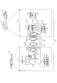
- FIG. 2 is a block diagram illustrating a configuration example of the power transmission system 10.
- the power transmission system 10 includes a power transmission device 100 and a power reception device 200.
- the power transmission apparatus 100 includes a power source 110, an ADC (AC / DC Converter) 120, a CPU (Central Processing Unit) 130, an information communication unit 140, and a power transmission circuit 150.
- ADC AC / DC Converter
- CPU Central Processing Unit
- the ADC 120 converts AC power supplied from the power source 110 into DC power.
- the converted DC power is sent to the power transmission circuit 150.
- the CPU 130 controls the operation of each unit (for example, the power supply 110, the ADC 120, the information communication unit 140, and the power transmission circuit 150) of the power transmission device 100.
- the information communication unit 140 includes a modulation / demodulation circuit 141 for modulating or demodulating communication data communicated with the power receiving apparatus 200.
- the information communication unit 140 transmits control information from the power transmission apparatus 100 to the power reception apparatus 200 via the coil CL.
- the information communication unit 140 receives data from the power receiving device 200 to the power transmitting device 100 via the coil CL.
- This data includes, for example, search result data obtained by underwater exploration or bottom exploration by the power receiving device 200.
- the information communication unit 140 allows the underwater vehicle 60 to quickly perform data communication with the underwater vehicle 60 while performing operations such as data collection.
- the power transmission circuit 150 includes a driver 151 and a resonance circuit 152.
- the driver 151 converts the DC power from the ADC 120 into an AC voltage (pulse waveform) having a predetermined frequency.
- the resonance circuit 152 includes a capacitor CA and a power transmission coil CLA, and generates an AC voltage with a sine wave waveform from an AC voltage with a pulse waveform from the driver 151.
- the power transmission coil CLA resonates at a predetermined resonance frequency according to the AC voltage applied from the driver 151.
- the power transmission coil CLA is impedance matched to the output impedance of the power transmission device 100.
- the predetermined frequency related to the AC voltage obtained by the conversion by the driver 151 corresponds to the transmission frequency of power transmission between the power transmission device 100 and the power reception device 200 and corresponds to the resonance frequency.
- this transmission frequency is set based on the Q value of each coil CL. Details of the set transmission frequency will be described later.
- the power receiving apparatus 200 includes a power receiving circuit 210, a CPU 220, a charge control circuit 230, a secondary battery 240, and an information communication unit 250.
- the power receiving circuit 210 includes a rectifier circuit 211, a regulator 212, and a resonance circuit 213.
- the resonance circuit 213 includes a capacitor CB and a power reception coil CLB, and receives AC power transmitted from the power transmission coil CLA.
- the power receiving coil CLB is impedance matched to the input impedance of the power receiving device 200.
- the rectifier circuit 211 converts AC power induced in the power receiving coil CLB into DC power.
- the regulator 212 converts the DC voltage sent from the rectifier circuit 211 into a predetermined voltage that is suitable for charging the secondary battery 240.
- the CPU 220 controls the operation of each unit of the power receiving device 200 (for example, the power receiving circuit 210, the charging control circuit 230, the secondary battery 240, and the information communication unit 250).
- the charging control circuit 230 controls charging to the secondary battery 240 according to the type of the secondary battery 240. For example, when the secondary battery 240 is a lithium ion battery, the charging control circuit 230 starts charging the secondary battery 240 with a constant voltage and DC power from the regulator 212.
- the secondary battery 240 stores the electric power transmitted from the power transmission device 100.
- the secondary battery 240 is, for example, a lithium ion battery.
- the information communication unit 250 includes a modulation / demodulation circuit 251 for modulating or demodulating communication data communicated with the power transmission device 100.
- the information communication unit 250 receives control information from the power transmission device 100 to the power reception device 200 via the coil CL.
- the information communication unit 250 transmits data from the power receiving device 200 to the power transmitting device 100 via the coil CL.
- This data includes, for example, search result data obtained by underwater exploration or bottom exploration by the power receiving device 200.
- the information communication unit 250 allows the underwater vehicle 60 to quickly perform data communication with the ship 50 while performing operations such as data collection.
- the relay coil CLC forms a resonance circuit together with the capacitor CC, like the power transmission coil CLA and the power reception coil CLB. That is, in this embodiment, electric power is transmitted by the magnetic resonance method by arranging the resonance circuits in multiple stages in water.
- the resonance circuit 152 when a current flows through the power transmission coil CLA of the power transmission device 100, a magnetic field is generated around the power transmission coil CLA.
- the generated vibration of the magnetic field is transmitted to a resonance circuit including a relay coil CLC that resonates at the same frequency or a resonance circuit 213 including a power receiving coil CLB.
- a current is excited in the relay coil CLC due to the vibration of the magnetic field, a current flows, and a magnetic field is further generated around the relay coil CLC.
- the generated vibration of the magnetic field is transmitted to a resonance circuit including another relay coil CLC that resonates at the same frequency or a resonance circuit 213 including a power receiving coil CLB.
- an alternating current is induced in the power receiving coil CLB by the vibration of the magnetic field of the relay coil CLC or the power transmitting coil CLA.
- the induced alternating current is rectified, converted into a predetermined voltage, and the secondary battery 240 is charged.
- FIG. 3 is a schematic diagram showing an example of a simulation model 300 used for the first simulation.
- the simulation model 300 includes a power transmission coil CL ⁇ and a power receiving coil CLB.
- the power transmission coil CL ⁇ is a coil used for power transmission, and includes, for example, a power transmission coil CLA and a relay coil CLC.
- the simulation model 300 is placed in the sea and simulated.
- the y direction is a direction orthogonal to the water surface 90 and is a direction in which power is transmitted.
- the xz plane is parallel to the water surface 90.
- the number of turns of the relay coil CLC) is 10, and the wire diameter of the power transmission coil CL ⁇ (power transmission coil CLA, relay coil CLC) is 9.1 mm. That is, the coil characteristics of the power transmission coil CLA and the relay coil CLC are the same. Therefore, the power transmission coil CLA and the relay coil CLC have, for example, the same frequency characteristics of the Q value.
- the number of turns of the power receiving coil CLB is 23, and the wire diameter of the power receiving coil CLB is 2.0 mm.
- the power receiving coil CLB is often mounted on various devices (for example, an underwater vehicle 60 described later). Therefore, the diameter of the power receiving coil CLB is often smaller than the diameters of the power transmitting coil CLA and the relay coil CLC for power transmission. When the diameter of the power receiving coil CLB is reduced, the inductance (L) of the coil is reduced. In comparison with the power transmission coil CL ⁇ , the power receiving coil CLB is often increased in the number of turns of the coil in order to suppress a decrease in inductance.
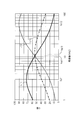
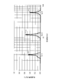
- FIG. 4 is a graph showing an example of the frequency characteristic of the Q value of each coil when the simulation model 300 is used.
- the horizontal axis in FIG. 4 indicates the frequency, and the vertical axis indicates the Q value.
- FIG. 4 shows a frequency characteristic L11 of the Q value of the power transmission coil CL ⁇ , a frequency characteristic L12 of the Q value of the power receiving coil CLB, and a frequency characteristic L13 of a virtual Q value described later.
- the Q value represents the sharpness of the resonance peak of the resonance circuit. Therefore, the transmission efficiency by the coil CL improves as the Q value increases.
- the Q value is represented by the following (Equation 1).
- the angular frequency ⁇ is expressed by the following (Equation 2) when the inductance component L and the capacitance component C are used.
- the virtual Q value indicated by the frequency characteristic L13 in FIG. 4 is derived based on the Q value of the power transmission coil CL ⁇ and the Q value of the power receiving coil CLB.
- Q3 is expressed by the following (formula 3).
- Q3 as the virtual Q value is calculated based on, for example, Q1 and Q2 for each frequency, and the frequency characteristic L13 is derived.
- Q3 is the geometric mean value of Q1 and Q2.
- a frequency fcp1 (for example, a frequency of 11 kHz) serving as an intersection (cross point) between the frequency characteristics L11 and L12, that is, in the vicinity of the frequency fcp1 where Q1 and Q2 are the same value. It can be understood that there is a maximum Q value at the position of the frequency fq13 (for example, the frequency of 12.3 kHz). Note that the specific Q value depends on the coil characteristics of the coil CL (each parameter related to the coil CL).
- the power transmission coil CL ⁇ has a larger coil diameter than the power receiving coil CLB. For this reason, the power transmission coil CL ⁇ has an inductance (L) larger than that of the power receiving coil CLB. Therefore, according to (Equation 2), the angular frequency ⁇ of the power transmission coil CL ⁇ is smaller than that of the power reception coil CLB. Therefore, the frequency fq11 at which the Q value of the power transmission coil CL ⁇ is maximum is the Q value of the power reception coil CLB. Becomes lower than the maximum frequency fq12.
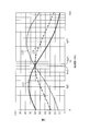
- FIG. 5 is a graph showing an example of frequency characteristics of transmission efficiency of each coil when the simulation model 300 is used.
- the horizontal axis in FIG. 5 indicates the frequency, and the vertical axis indicates the current or voltage transmission efficiency.
- This transmission characteristic indicates the ratio of the received power of the power receiving coil CLB to the transmission power of the power transmitting coil CLA, and corresponds to the S21 parameter.
- a peak value P11 for example, a value of 0.46 of transmission efficiency appears at the position of the frequency fq11 corresponding to the maximum value of Q1.
- a peak value P12 for example, a value of 0.38) of transmission efficiency appears at the position of the frequency fq12 corresponding to the maximum value of Q2.
- a peak value P13 of transmission efficiency (for example, a value of 0.57) appears at the position of the frequency fq13 corresponding to the maximum value of Q3.
- transmission efficiency becomes high, so that Q value is large, and transmission of electric power energy becomes inadequate when Q value is smaller than fixed value, and electric power transmission becomes difficult.
- the transmission efficiency ⁇ of power is derived by squaring the transmission efficiency on the vertical axis in FIG.
- the power transmission efficiency ⁇ at the frequency fq11 is 21.3%.
- the power transmission efficiency ⁇ at the frequency fq12 is 14.8%.
- the power transmission efficiency ⁇ at the frequency fq13 is 32.8%.
- the frequency at which the transmission efficiency ⁇ increases (for example, becomes the maximum) by deriving the geometric mean of the Q values of the coils. Can be derived.
- a CPU of a simulation apparatus for example, a PC (Personal Computer)
- a CPU 130 of the power transmission apparatus 100 for example, a PC (Personal Computer)
- a CPU 220 of the power reception apparatus 200 for example, a PC (Personal Computer)
- the peak value P13 is the maximum among the peak values P11 to P13. Accordingly, by selecting the frequency at which the peak value P13 as the maximum value of the transmission efficiency is obtained, that is, the frequency fq13 derived from the maximum value of the frequency characteristic L13 of Q3, the power transmission system 10 causes the power transmission coil CL ⁇ to It can be understood that the transmission efficiency of the power transmission by the magnetic field resonance method using the power receiving coil CLB can be maximized.
- the position of the frequency fcp1 at the cross point where the frequency characteristic L11 of Q1 and the frequency characteristic L11 of Q2 intersect may be slightly different from the position of the frequency fq13 corresponding to the maximum value of Q3.
- the magnitude of Q3 at the frequency fcp1 is close to the maximum value of Q3 (that is, Q3 at the frequency fq13). Therefore, even when any frequency between the frequency fcp1 and the frequency fq13 is set as the transmission frequency, the transmission efficiency approximate to the peak value P13 can be obtained and the transmission efficiency can be improved.
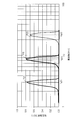
- FIG. 6 is a schematic diagram showing an example of a simulation model 600 used for the second simulation.
- the simulation model 600 is the same as the simulation model 300 except for the characteristics of the power receiving coil CLB. In the second simulation, the simulation model 600 is placed in the sea and simulated.
- FIG. 7 is a graph showing an example of the frequency characteristic of the Q value of each coil when the simulation model 600 is used.
- the horizontal axis indicates the frequency
- the vertical axis indicates the Q value.
- FIG. 7 shows a frequency characteristic L21 of the Q value of the power transmission coil CL ⁇ , a frequency characteristic L22 of the Q value of the power receiving coil CLB, and a frequency characteristic L23 of the virtual Q value. Note that the method for deriving Q3 as the virtual Q value is the same as in the first simulation, and Q3 is based on the geometric mean value of Q1 and Q2.
- the maximum value of Q2 is also small.
- the frequency fcp2 for example, frequency 8 kHz
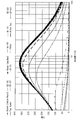
- FIG. 8 is a graph showing an example of frequency characteristics of transmission efficiency of each coil when the simulation model 600 is used.
- the horizontal axis in FIG. 5 indicates the frequency, and the vertical axis indicates the current or voltage transmission efficiency.
- This transmission characteristic indicates the ratio of the received power of the power receiving coil CLB to the transmitted power of the power transmitting coil CLA, as in the first simulation, and corresponds to the S21 parameter.
- a peak value P21 of transmission efficiency (for example, a value of 0.76) appears at the position of the frequency fq21 corresponding to the maximum value of Q1.
- a peak value P22 (for example, a value of 0.70) of transmission efficiency appears at the position of the frequency fq22 corresponding to the maximum value of Q2.
- a transmission efficiency peak value P23 (for example, a value of 0.78) appears at the position of the frequency fq23 corresponding to the maximum value of Q3.
- the power transmission efficiency ⁇ at the frequency fq21 is 58.3%.
- the power transmission efficiency ⁇ at the frequency fq22 is 48.5%.
- the power transmission efficiency ⁇ at the frequency fq23 is 61.6%.
- the peak value P23 is the maximum among the peak values P21 to P23. Therefore, by selecting the frequency fq23 derived from the maximum value of the frequency characteristic L23 of Q3, that is, the frequency at which the peak value P23 as the maximum value of transmission efficiency is obtained, the power transmission coil CL ⁇ and the power receiving coil CLB are used. It can be understood that the transmission efficiency of power transmission by the magnetic field resonance method can be maximized.
- the position of the frequency fcp2 at the cross point where the frequency characteristic L21 of Q1 and the frequency characteristic L22 of Q2 intersect may be slightly different from the position of the frequency fq23 corresponding to the maximum value of Q3.
- the magnitude of Q3 at the frequency fcp2 is close to the maximum value of Q3 (that is, Q3 at the frequency fq23). Therefore, even when any frequency between the frequency fcp2 and the frequency fq23 is set as the transmission frequency, the transmission efficiency approximate to the peak value P23 is obtained, and the transmission efficiency can be improved.
- FIG. 9 is a graph showing an example of frequency characteristics of the Q value of the coil CL for each medium in which the coil CL is arranged. Since the conductivity differs for each medium, FIG. 9 can also be said to be a graph showing the frequency characteristics of the Q value of the coil CL for each conductivity.
- a medium Debye model water “Water (Debye Model)”, distilled water “Water (distilled)”, normal water (for example, tap water) “Water”, seawater “Water_sea”, and other media are used. included.
- the frequency characteristics of the Debye model for water, distilled water, normal water, and seawater are the default material characteristics attached to the simulator (apparatus for simulating the frequency characteristics of the Q value of the coil CL for each medium). It was obtained.
- the frequency characteristic regarding the tap water measured with the conductivity meter is shown as “Tap Water”.
- the diameter of the coil CL was 4.0 m
- the wire diameter of the coil was 23.6 mm
- the number of turns of the coil was 5.
- the frequency characteristic of the Q value of the coil CL differs for each medium. Therefore, in the first simulation and the second simulation described above, it can be understood that, for example, when the simulation is performed underwater instead of in the sea, the Q value obtained is changed and the Q value is increased.
- the power transmission device 100 transmits power to the power reception device 200 having the power reception coil CLB in water.
- Power transmission device 100 power transmission coil CLA that transmits power to power reception coil CLB via a magnetic field, and driver 151 that transmits AC power of a predetermined frequency (for example, 11 kHz to 12.3 kHz, 8 kHz to 8.5 kHz) to power transmission coil CLA
- a capacitor CA that is connected to the power transmission coil CLA and forms a resonance circuit 152 that resonates with the power transmission coil CLA.
- the predetermined frequencies are frequencies fq13 and fq23 at which the geometric mean value (for example, Q3) of the Q value (for example, Q1) of the power transmission coil CLA and the Q value (for example, Q2) of the power reception coil CLB and the Q value of the power transmission coil CLA. And the frequencies fcp1 and fcp2 at which the Q values of the power receiving coils are the same.
- the driver 151 is an example of a power transmission unit.
- the capacitor CA is an example of a first capacitor.
- Q1 is an example of the Q value of the power transmission coil CLA.
- Q2 is an example of the Q value of the power receiving coil CLB.
- Q3 is an example of a geometric mean value of Q1 and Q2, that is, a virtual Q value derived by (Expression 2).
- the frequencies fq13 and fq23 are an example of the first frequency.
- the frequencies fcp1 and fcp2 are an example of the second frequency.
- the power transmission apparatus 100 determines the frequency (transmission frequency) for power transmission by taking into consideration the geometric mean of both the Q value of the power transmission coil CLA and the Q value of the power reception coil CLB, thereby transmitting power transmission. Efficiency can be improved.
- the transmission frequency the transmission efficiency of the coil of the power transmission coil CLA can be increased, but the transmission efficiency of the power reception coil CLB is decreased.
- the frequency at which the Q value of the power receiving coil CLB is near the maximum value is the transmission frequency
- the transmission efficiency of the coil of the power receiving coil CLB can be increased, but the transmission efficiency by the power transmitting coil CLA is decreased. That is, a suitable transmission frequency differs between the power transmission side and the power reception side.
- the power transmission apparatus 100 uses a plurality of coils by setting a frequency in the vicinity where the average value (synergistic average value) of the Q value of the power transmission coil CLA and the Q value of the power receiving coil CLB is the maximum as the transmission frequency.
- the transmission efficiency of the power transmission system 10 as a whole can be improved by taking into account the Q values of different CL.
- the predetermined frequencies may be frequencies fq13 and fq23.
- the power transmission device 100 is connected to the relay coil CLC with at least one relay coil CLC that transmits power to the power reception coil CLB using the magnetic field from the power transmission coil CLA, and resonates at the above frequency together with the relay coil CLC.
- You may provide at least 1 capacitor
- the frequency characteristic of the Q value of the relay coil CLC may be the same as the frequency characteristic of the Q value of the power transmission coil CLA.
- the capacitor CC is an example of a second capacitor.
- the power transmission device 100 has the same Q value for the power transmission coil CLA and the Q value for the relay coil CLC, so that the power transmission coil CLA and the relay coil CLC have the same characteristics related to power transmission. Transmission loss between the two can be reduced. Further, in the power transmission device 100, since the frequency near the maximum value (the geometric mean value) of the Q value of the relay coil CLC and the Q value of the power receiving coil CLB is the transmission frequency, the relay coil CLC and the power receiving coil Transmission loss with the CLB can also be reduced.
- the power transmission coil CLA may transmit power in a direction substantially orthogonal to the water surface 90.
- the power transmission device 100 can extend the power transmission distance in the water depth direction, can supply power to the power reception device 200 located in a deep water location (for example, deep sea), and can improve the work efficiency of the power reception device 200.
- the power transmission coil CLA may transmit power and communicate data.
- the power receiving apparatus 200 can charge the power from the power transmission apparatus 100 while suppressing a decrease in activity efficiency such as data collection, and can perform data communication with the power transmission apparatus 100.
- the power reception device 200 (for example, the underwater vehicle 60) does not need to contact the power transmission coil CLA even in an environment where there is a flow of water, and the power by the magnetic resonance method. A reduction in transmission efficiency can be suppressed and power can be stably supplied. Therefore, the underwater vehicle 60 can receive continuous power supply while performing activities such as data collection, and the operating rate of the underwater vehicle 60 when receiving power supply is improved. Therefore, the power transmission device 100 can improve the efficiency of data collection activities in water.
- the power transmission device 100 can transmit power wirelessly by the magnetic resonance method by using the power transmission coil CLA of the power transmission device 100 and the power reception coil CLB of the power reception device 200. Moreover, since the underwater vehicle 60 can receive power without moving the underwater vehicle 60 to a predetermined power supply location, the underwater vehicle 60 can move freely even during power supply, and position-free power transmission is possible. It becomes. Therefore, the power transmission device 100 can suppress the activity of the underwater vehicle 60 underwater or at the bottom 95 from being inhibited. Therefore, the underwater vehicle 60 can expand the work range even during charging, and can be continuously charged during work. Moreover, since the underwater vehicle 60 can be charged at an arbitrary timing, the working time can be shortened.
- the power transmission device 100 can extend the power transmission distance by continuous electromagnetic induction by using the relay coil CLC. For example, as illustrated in FIG. 1, by arranging the relay coils CLC in multiple stages from the vicinity of the water surface 90 toward the bottom of the water, the power transmission device 100 can transmit power to a deep water position (for example, a water depth of 1000 m or more). In this case, the power transmission device 100 can wirelessly transmit power to the underwater vehicle 60 that performs mining and investigation of the seabed resources, and can suppress a decrease in the operating rate of the underwater vehicle 60 during power feeding.
- a deep water position for example, a water depth of 1000 m or more.
- the power transmission device 100 can wirelessly transmit power to the underwater vehicle 60 that performs mining and investigation of the seabed resources, and can suppress a decrease in the operating rate of the underwater vehicle 60 during power feeding.
- the underwater vehicle 60 can be active. In this case, the underwater vehicle 60 can be reduced in size and weight.
- the first embodiment has been described as an example of the technique in the present disclosure.
- the technology in the present disclosure is not limited to this, and can also be applied to embodiments in which changes, replacements, additions, omissions, and the like are performed.
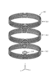
- the power transmission system 10 may include the reflection coil CLR as one of the power transmission coils CL ⁇ .
- the reflection coil CLR is disposed between the power transmission coil CLA and the water surface 90.
- the reflection coil CLR reflects the magnetic field emitted from the power transmission coil CLA toward the water surface 90 toward the water bottom 95.
- FIG. 10 is a schematic diagram showing an example of an environment where the power transmission system 10 provided with the reflection coil CLR is placed.
- the power transmission system 10 can suppress interference between the magnetic field emitted from the power transmission coil CLA and the communication of the ultra-long wave (VLF) band or the ultra-long wave (ULF) on or in water. Therefore, the power transmission system 10 can improve the transmission efficiency of the power transmitted from the power transmission coil to the power reception coil by providing the reflection coil CLR.
- VLF ultra-long wave
- ULF ultra-long wave
- the reflection coil CLR is not connected to a capacitor like the power reception coil CLB and the relay coil CLC, and does not form a resonance circuit. That is, the reflection coil CLR is a closed loop without a capacitor.
- a second reflection coil having a smaller coil diameter than the reflection coil CLR may be arranged inside the reflection coil CLR shown in FIG. 10 concentrically with the reflection coil CLR.
- the underwater vehicle 60 includes the secondary battery 240, so that underwater charging is possible.
- the underwater vehicle 60 may not include the secondary battery 240. Even in this case, the underwater vehicle 60 can be supplied with electric power through each coil CL, that is, can be supplied with water underwater.
- the power transmission system 10 is exemplified by a submarine camera system that collects data in the sea or at the bottom of the sea, but may be applied to other uses.
- the power receiving device 200 may be provided in an underwater robot or an unmanned explorer equipped with various sensors, and may be disposed in the water or in the bottom 95. This makes it possible to manage marine resources and aquaculture, maintain and manage infrastructure systems such as bridges and dams, and monitor the seabed of harbors, etc., using underwater robots and unmanned explorers.
- the power transmission coil CLA, the relay coil CLC, and the power reception coil CLB are arranged side by side from the water surface 90 toward the water bottom 95, but the arrangement direction of the coil CL is limited to this. Absent.
- the power transmission coil CLA, the relay coil CLC, and the power reception coil CLB may be arranged side by side in the direction along the water surface 90 or the water bottom 95. Thereby, the power transmission apparatus 100 can transmit electric power horizontally in water.
- the power transmission coil CLA, the relay coil CLC, and the power reception coil CLB are arranged side by side from the water surface 90 toward the water bottom 95, but this may be reversed. That is, the power transmission coil CLA, the relay coil CLC, and the power reception coil CLB may be arranged side by side from the water bottom 95 toward the water surface 90.
- a geothermal power generator may be used as the power source 110 of the power transmission apparatus 100 and the geothermal power generator may be connected to the power transmission coil CLA via the electric wire 20.
- the power transmission device 100 may not be installed on the ship 50.
- various generators for example, solar power generator, wind power generator, wave power generator
- various generators geothermal generators
- a part of the power transmission device 100 may be mounted.
- various generators may be used as the power source 110 of the power transmission device 100.
- the CPUs 130 and 220 are exemplified, but a processor other than the CPUs 130 and 220 may be used.
- the processor may be physically configured in any manner. Further, if a programmable processor is used, the processing contents can be changed by changing the program, so that the degree of freedom in designing the processor can be increased.
- the processor may be composed of one semiconductor chip or physically composed of a plurality of semiconductor chips. When configured by a plurality of semiconductor chips, each control of the first embodiment may be realized by separate semiconductor chips. In this case, it can be considered that a plurality of semiconductor chips constitute one processor.
- the processor may be configured by a member (capacitor or the like) having a function different from that of the semiconductor chip. Further, one semiconductor chip may be configured so as to realize the functions of the processor and other functions.
- This disclosure is useful for a power transmission device that can improve the transmission efficiency of non-contact power transmission to a power receiving device in water.
Abstract
L'invention concerne un dispositif de transmission de puissance qui peut améliorer l'efficacité de transmission de la transmission de puissance sans contact vers un dispositif de réception de puissance dans l'eau. Le dispositif de transmission de puissance transmet de l'énergie, dans l'eau, au dispositif de réception de puissance qui possède une bobine de réception de puissance. Le dispositif de transmission de puissance comprend : une bobine de transmission de puissance qui transmet de l'énergie à la bobine de réception de puissance par l'intermédiaire d'un champ magnétique ; une unité de transmission de puissance qui transmet une puissance en courant alternatif d'une fréquence prescrite à la bobine de transmission de puissance ; et un premier condensateur qui est connecté à la bobine de transmission de puissance et forme un circuit résonnant qui résonne avec la bobine de transmission de puissance. La fréquence prescrite est une fréquence quelconque entre une première fréquence à laquelle la valeur moyenne géométrique de la valeur Q de la bobine de transmission de puissance et la valeur Q de la bobine de réception de puissance est maximale, et une seconde fréquence à laquelle la valeur Q de la bobine de transmission de puissance et la valeur Q de la bobine de réception de puissance ont la même valeur.
Priority Applications (1)
| Application Number | Priority Date | Filing Date | Title |
|---|---|---|---|
| US16/314,139 US10790705B2 (en) | 2016-06-30 | 2017-06-19 | Power transmission device |
Applications Claiming Priority (2)
| Application Number | Priority Date | Filing Date | Title |
|---|---|---|---|
| JP2016130997A JP6737648B2 (ja) | 2016-06-30 | 2016-06-30 | 送電装置 |
| JP2016-130997 | 2016-06-30 |
Publications (1)
| Publication Number | Publication Date |
|---|---|
| WO2018003568A1 true WO2018003568A1 (fr) | 2018-01-04 |
Family
ID=60786848
Family Applications (1)
| Application Number | Title | Priority Date | Filing Date |
|---|---|---|---|
| PCT/JP2017/022515 WO2018003568A1 (fr) | 2016-06-30 | 2017-06-19 | Dispositif de transmission de puissance |
Country Status (3)
| Country | Link |
|---|---|
| US (1) | US10790705B2 (fr) |
| JP (3) | JP6737648B2 (fr) |
| WO (1) | WO2018003568A1 (fr) |
Cited By (2)
| Publication number | Priority date | Publication date | Assignee | Title |
|---|---|---|---|---|
| WO2018207899A1 (fr) * | 2017-05-10 | 2018-11-15 | パナソニック株式会社 | Dispositif de transmission d'énergie |
| US11569689B2 (en) * | 2018-07-31 | 2023-01-31 | Panasonic Intellectual Property Management Co., Ltd. | Power receiving device, power transmitting device, and underwater power supply system |
Families Citing this family (2)
| Publication number | Priority date | Publication date | Assignee | Title |
|---|---|---|---|---|
| JP6568133B2 (ja) * | 2017-03-30 | 2019-08-28 | パナソニック株式会社 | 伝送コイル及び送電装置 |
| JP7378084B2 (ja) * | 2019-12-25 | 2023-11-13 | 株式会社サムスン日本研究所 | 非接触給電システム |
Citations (3)
| Publication number | Priority date | Publication date | Assignee | Title |
|---|---|---|---|---|
| WO2014034491A1 (fr) * | 2012-08-31 | 2014-03-06 | 日本電気株式会社 | Dispositif de transmission de puissance électrique et procédé de transmission de puissance électrique |
| WO2015087724A1 (fr) * | 2013-12-09 | 2015-06-18 | 有限会社 アール・シー・エス | Antenne à boucle magnétique et dispositif de communication à champ magnétique l'utilisant |
| WO2017013825A1 (fr) * | 2015-07-21 | 2017-01-26 | パナソニックIpマネジメント株式会社 | Dispositif d'envoi d'énergie |
Family Cites Families (14)
| Publication number | Priority date | Publication date | Assignee | Title |
|---|---|---|---|---|
| WO1998034319A1 (fr) * | 1997-02-03 | 1998-08-06 | Sony Corporation | Equipement et procede pour le transfert d'energie electrique |
| JP2005102101A (ja) | 2003-09-01 | 2005-04-14 | Matsushita Electric Ind Co Ltd | ゲートアンテナ装置 |
| US20110076940A1 (en) * | 2009-09-25 | 2011-03-31 | Mark Rhodes | Underwater wireless communications hotspot |
| JP2011160634A (ja) * | 2010-02-04 | 2011-08-18 | Casio Computer Co Ltd | 電力伝送システム及び送電装置 |
| US8970070B2 (en) * | 2010-07-02 | 2015-03-03 | Panasonic Intellectual Property Management Co., Ltd. | Wireless power transmission system |
| JP6035711B2 (ja) * | 2011-07-21 | 2016-11-30 | ソニー株式会社 | 検知装置、受電装置、送電装置、非接触電力伝送システム及び検知方法 |
| JP2013110805A (ja) * | 2011-11-18 | 2013-06-06 | Nec Corp | 非接触給電システム及び給電方法 |
| JP5637319B2 (ja) | 2011-12-07 | 2014-12-10 | 株式会社Ihi | 電力伝送システム |
| JP2014103147A (ja) * | 2012-11-16 | 2014-06-05 | Panasonic Corp | 集合電線、これを用いた送電装置および電子機器、ならびにワイヤレス電力伝送システム |
| WO2014129531A1 (fr) * | 2013-02-20 | 2014-08-28 | 日本電気株式会社 | Système de transmission de puissance, appareil de transmission, appareil de réception, et procédé de transmission de puissance |
| CN105191064B (zh) * | 2013-05-10 | 2018-07-24 | 株式会社 Ihi | 非接触供电系统 |
| JP6387222B2 (ja) * | 2013-08-28 | 2018-09-05 | ソニー株式会社 | 給電装置、受電装置、給電システム、および、給電装置の制御方法 |
| JP2016059146A (ja) * | 2014-09-08 | 2016-04-21 | 株式会社リューテック | 海水中給電システム |
| US10181729B1 (en) * | 2015-11-13 | 2019-01-15 | X Development Llc | Mobile hybrid transmit/receive node for near-field wireless power delivery |
-
2016
- 2016-06-30 JP JP2016130997A patent/JP6737648B2/ja active Active
-
2017
- 2017-06-19 WO PCT/JP2017/022515 patent/WO2018003568A1/fr active Application Filing
- 2017-06-19 US US16/314,139 patent/US10790705B2/en active Active
-
2020
- 2020-07-15 JP JP2020121539A patent/JP6919033B2/ja active Active
-
2021
- 2021-07-21 JP JP2021120833A patent/JP7222035B2/ja active Active
Patent Citations (3)
| Publication number | Priority date | Publication date | Assignee | Title |
|---|---|---|---|---|
| WO2014034491A1 (fr) * | 2012-08-31 | 2014-03-06 | 日本電気株式会社 | Dispositif de transmission de puissance électrique et procédé de transmission de puissance électrique |
| WO2015087724A1 (fr) * | 2013-12-09 | 2015-06-18 | 有限会社 アール・シー・エス | Antenne à boucle magnétique et dispositif de communication à champ magnétique l'utilisant |
| WO2017013825A1 (fr) * | 2015-07-21 | 2017-01-26 | パナソニックIpマネジメント株式会社 | Dispositif d'envoi d'énergie |
Non-Patent Citations (2)
| Title |
|---|
| DAI FUTAGAMI ET AL.: "Creation of industrial value of sea floor by implementation of undersea wireless power transfer", 2015 PROCEEDINGS OF THE SOCIETY CONFERENCE OF IEICE 1, 8 September 2015 (2015-09-08), pages S62 - S63 * |
| RYOSUKE HASABA ET AL.: "Study of wireless power transmission for under seawater using EM simulation", PROCEEDINGS OF THE 2016 IEICE GENERAL CONFERENCE TSUSHIN 1, 15 March 2016 (2016-03-15), pages 681 * |
Cited By (4)
| Publication number | Priority date | Publication date | Assignee | Title |
|---|---|---|---|---|
| WO2018207899A1 (fr) * | 2017-05-10 | 2018-11-15 | パナソニック株式会社 | Dispositif de transmission d'énergie |
| US11031820B2 (en) | 2017-05-10 | 2021-06-08 | Panasonic Corporation | Power transmitting device |
| US11502550B2 (en) | 2017-05-10 | 2022-11-15 | Panasonic Holdings Corporation | Power transmitting device that transmits power to power receiving device having power receiving coil in water |
| US11569689B2 (en) * | 2018-07-31 | 2023-01-31 | Panasonic Intellectual Property Management Co., Ltd. | Power receiving device, power transmitting device, and underwater power supply system |
Also Published As
| Publication number | Publication date |
|---|---|
| US10790705B2 (en) | 2020-09-29 |
| JP2021170932A (ja) | 2021-10-28 |
| JP6737648B2 (ja) | 2020-08-12 |
| JP2020178531A (ja) | 2020-10-29 |
| US20190229557A1 (en) | 2019-07-25 |
| JP7222035B2 (ja) | 2023-02-14 |
| JP2018007400A (ja) | 2018-01-11 |
| JP6919033B2 (ja) | 2021-08-11 |
Similar Documents
| Publication | Publication Date | Title |
|---|---|---|
| JP6919033B2 (ja) | 送電装置 | |
| WO2017013825A1 (fr) | Dispositif d'envoi d'énergie | |
| JP6553465B2 (ja) | スマート無線給電のための磁界を制御する方法 | |
| WO2018079082A1 (fr) | Dispositif de transmission de puissance électrique | |
| JP6594373B2 (ja) | 送電装置 | |
| Yoshida et al. | Underwater wireless power transfer for non-fixed unmanned underwater vehicle in the ocean | |
| US11569689B2 (en) | Power receiving device, power transmitting device, and underwater power supply system | |
| WO2018180355A1 (fr) | Bobine de transmission et appareil de transmission de puissance | |
| CN109428325A (zh) | 一种深海机器人供电系统 | |
| JP6620906B1 (ja) | 水中通信装置及び水中通信システム | |
| JP6492651B2 (ja) | 給電システム、移動体および給電装置 | |
| US20210281328A1 (en) | Underwater communication device and underwater communication system | |
| JP2016207872A (ja) | 無線給電システムおよび無線給電方法 | |
| WO2016170769A1 (fr) | Système d'alimentation électrique sans fil et procédé d'alimentation électrique sans fil | |
| Haibing et al. | Comparison of two electromagnetic couplers in an inductive power transfer system for autonomous underwater vehicle docking application | |
| US11699923B2 (en) | Power receiver apparatus, power transmission voltage control method, and underwater power supply system | |
| US20220368162A1 (en) | Power transmission coil, power transmission device, and underwater power supply systems |
Legal Events
| Date | Code | Title | Description |
|---|---|---|---|
| 121 | Ep: the epo has been informed by wipo that ep was designated in this application |
Ref document number: 17819927 Country of ref document: EP Kind code of ref document: A1 |
|
| NENP | Non-entry into the national phase |
Ref country code: DE |
|
| 122 | Ep: pct application non-entry in european phase |
Ref document number: 17819927 Country of ref document: EP Kind code of ref document: A1 |