WO2018003568A1 - Power transmission device - Google Patents
Power transmission device Download PDFInfo
- Publication number
- WO2018003568A1 WO2018003568A1 PCT/JP2017/022515 JP2017022515W WO2018003568A1 WO 2018003568 A1 WO2018003568 A1 WO 2018003568A1 JP 2017022515 W JP2017022515 W JP 2017022515W WO 2018003568 A1 WO2018003568 A1 WO 2018003568A1
- Authority
- WO
- WIPO (PCT)
- Prior art keywords
- coil
- power
- power transmission
- frequency
- value
- Prior art date
Links
Images

Classifications
-
- H—ELECTRICITY
- H02—GENERATION; CONVERSION OR DISTRIBUTION OF ELECTRIC POWER
- H02J—CIRCUIT ARRANGEMENTS OR SYSTEMS FOR SUPPLYING OR DISTRIBUTING ELECTRIC POWER; SYSTEMS FOR STORING ELECTRIC ENERGY
- H02J50/00—Circuit arrangements or systems for wireless supply or distribution of electric power
- H02J50/10—Circuit arrangements or systems for wireless supply or distribution of electric power using inductive coupling
- H02J50/12—Circuit arrangements or systems for wireless supply or distribution of electric power using inductive coupling of the resonant type
-
- B—PERFORMING OPERATIONS; TRANSPORTING
- B60—VEHICLES IN GENERAL
- B60L—PROPULSION OF ELECTRICALLY-PROPELLED VEHICLES; SUPPLYING ELECTRIC POWER FOR AUXILIARY EQUIPMENT OF ELECTRICALLY-PROPELLED VEHICLES; ELECTRODYNAMIC BRAKE SYSTEMS FOR VEHICLES IN GENERAL; MAGNETIC SUSPENSION OR LEVITATION FOR VEHICLES; MONITORING OPERATING VARIABLES OF ELECTRICALLY-PROPELLED VEHICLES; ELECTRIC SAFETY DEVICES FOR ELECTRICALLY-PROPELLED VEHICLES
- B60L53/00—Methods of charging batteries, specially adapted for electric vehicles; Charging stations or on-board charging equipment therefor; Exchange of energy storage elements in electric vehicles
- B60L53/10—Methods of charging batteries, specially adapted for electric vehicles; Charging stations or on-board charging equipment therefor; Exchange of energy storage elements in electric vehicles characterised by the energy transfer between the charging station and the vehicle
- B60L53/12—Inductive energy transfer
-
- B—PERFORMING OPERATIONS; TRANSPORTING
- B60—VEHICLES IN GENERAL
- B60L—PROPULSION OF ELECTRICALLY-PROPELLED VEHICLES; SUPPLYING ELECTRIC POWER FOR AUXILIARY EQUIPMENT OF ELECTRICALLY-PROPELLED VEHICLES; ELECTRODYNAMIC BRAKE SYSTEMS FOR VEHICLES IN GENERAL; MAGNETIC SUSPENSION OR LEVITATION FOR VEHICLES; MONITORING OPERATING VARIABLES OF ELECTRICALLY-PROPELLED VEHICLES; ELECTRIC SAFETY DEVICES FOR ELECTRICALLY-PROPELLED VEHICLES
- B60L53/00—Methods of charging batteries, specially adapted for electric vehicles; Charging stations or on-board charging equipment therefor; Exchange of energy storage elements in electric vehicles
- B60L53/30—Constructional details of charging stations
- B60L53/31—Charging columns specially adapted for electric vehicles
-
- H—ELECTRICITY
- H01—ELECTRIC ELEMENTS
- H01F—MAGNETS; INDUCTANCES; TRANSFORMERS; SELECTION OF MATERIALS FOR THEIR MAGNETIC PROPERTIES
- H01F38/00—Adaptations of transformers or inductances for specific applications or functions
- H01F38/14—Inductive couplings
-
- B—PERFORMING OPERATIONS; TRANSPORTING
- B60—VEHICLES IN GENERAL
- B60L—PROPULSION OF ELECTRICALLY-PROPELLED VEHICLES; SUPPLYING ELECTRIC POWER FOR AUXILIARY EQUIPMENT OF ELECTRICALLY-PROPELLED VEHICLES; ELECTRODYNAMIC BRAKE SYSTEMS FOR VEHICLES IN GENERAL; MAGNETIC SUSPENSION OR LEVITATION FOR VEHICLES; MONITORING OPERATING VARIABLES OF ELECTRICALLY-PROPELLED VEHICLES; ELECTRIC SAFETY DEVICES FOR ELECTRICALLY-PROPELLED VEHICLES
- B60L2200/00—Type of vehicles
- B60L2200/32—Waterborne vessels
-
- B—PERFORMING OPERATIONS; TRANSPORTING
- B63—SHIPS OR OTHER WATERBORNE VESSELS; RELATED EQUIPMENT
- B63C—LAUNCHING, HAULING-OUT, OR DRY-DOCKING OF VESSELS; LIFE-SAVING IN WATER; EQUIPMENT FOR DWELLING OR WORKING UNDER WATER; MEANS FOR SALVAGING OR SEARCHING FOR UNDERWATER OBJECTS
- B63C11/00—Equipment for dwelling or working underwater; Means for searching for underwater objects
-
- H—ELECTRICITY
- H02—GENERATION; CONVERSION OR DISTRIBUTION OF ELECTRIC POWER
- H02J—CIRCUIT ARRANGEMENTS OR SYSTEMS FOR SUPPLYING OR DISTRIBUTING ELECTRIC POWER; SYSTEMS FOR STORING ELECTRIC ENERGY
- H02J50/00—Circuit arrangements or systems for wireless supply or distribution of electric power
- H02J50/80—Circuit arrangements or systems for wireless supply or distribution of electric power involving the exchange of data, concerning supply or distribution of electric power, between transmitting devices and receiving devices
-
- H—ELECTRICITY
- H02—GENERATION; CONVERSION OR DISTRIBUTION OF ELECTRIC POWER
- H02J—CIRCUIT ARRANGEMENTS OR SYSTEMS FOR SUPPLYING OR DISTRIBUTING ELECTRIC POWER; SYSTEMS FOR STORING ELECTRIC ENERGY
- H02J7/00—Circuit arrangements for charging or depolarising batteries or for supplying loads from batteries
- H02J7/00032—Circuit arrangements for charging or depolarising batteries or for supplying loads from batteries characterised by data exchange
- H02J7/00034—Charger exchanging data with an electronic device, i.e. telephone, whose internal battery is under charge
-
- Y—GENERAL TAGGING OF NEW TECHNOLOGICAL DEVELOPMENTS; GENERAL TAGGING OF CROSS-SECTIONAL TECHNOLOGIES SPANNING OVER SEVERAL SECTIONS OF THE IPC; TECHNICAL SUBJECTS COVERED BY FORMER USPC CROSS-REFERENCE ART COLLECTIONS [XRACs] AND DIGESTS
- Y02—TECHNOLOGIES OR APPLICATIONS FOR MITIGATION OR ADAPTATION AGAINST CLIMATE CHANGE
- Y02T—CLIMATE CHANGE MITIGATION TECHNOLOGIES RELATED TO TRANSPORTATION
- Y02T10/00—Road transport of goods or passengers
- Y02T10/60—Other road transportation technologies with climate change mitigation effect
- Y02T10/70—Energy storage systems for electromobility, e.g. batteries
-
- Y—GENERAL TAGGING OF NEW TECHNOLOGICAL DEVELOPMENTS; GENERAL TAGGING OF CROSS-SECTIONAL TECHNOLOGIES SPANNING OVER SEVERAL SECTIONS OF THE IPC; TECHNICAL SUBJECTS COVERED BY FORMER USPC CROSS-REFERENCE ART COLLECTIONS [XRACs] AND DIGESTS
- Y02—TECHNOLOGIES OR APPLICATIONS FOR MITIGATION OR ADAPTATION AGAINST CLIMATE CHANGE
- Y02T—CLIMATE CHANGE MITIGATION TECHNOLOGIES RELATED TO TRANSPORTATION
- Y02T10/00—Road transport of goods or passengers
- Y02T10/60—Other road transportation technologies with climate change mitigation effect
- Y02T10/7072—Electromobility specific charging systems or methods for batteries, ultracapacitors, supercapacitors or double-layer capacitors
-
- Y—GENERAL TAGGING OF NEW TECHNOLOGICAL DEVELOPMENTS; GENERAL TAGGING OF CROSS-SECTIONAL TECHNOLOGIES SPANNING OVER SEVERAL SECTIONS OF THE IPC; TECHNICAL SUBJECTS COVERED BY FORMER USPC CROSS-REFERENCE ART COLLECTIONS [XRACs] AND DIGESTS
- Y02—TECHNOLOGIES OR APPLICATIONS FOR MITIGATION OR ADAPTATION AGAINST CLIMATE CHANGE
- Y02T—CLIMATE CHANGE MITIGATION TECHNOLOGIES RELATED TO TRANSPORTATION
- Y02T90/00—Enabling technologies or technologies with a potential or indirect contribution to GHG emissions mitigation
- Y02T90/10—Technologies relating to charging of electric vehicles
- Y02T90/12—Electric charging stations
-
- Y—GENERAL TAGGING OF NEW TECHNOLOGICAL DEVELOPMENTS; GENERAL TAGGING OF CROSS-SECTIONAL TECHNOLOGIES SPANNING OVER SEVERAL SECTIONS OF THE IPC; TECHNICAL SUBJECTS COVERED BY FORMER USPC CROSS-REFERENCE ART COLLECTIONS [XRACs] AND DIGESTS
- Y02—TECHNOLOGIES OR APPLICATIONS FOR MITIGATION OR ADAPTATION AGAINST CLIMATE CHANGE
- Y02T—CLIMATE CHANGE MITIGATION TECHNOLOGIES RELATED TO TRANSPORTATION
- Y02T90/00—Enabling technologies or technologies with a potential or indirect contribution to GHG emissions mitigation
- Y02T90/10—Technologies relating to charging of electric vehicles
- Y02T90/14—Plug-in electric vehicles
Definitions
- the present disclosure relates to a power transmission device that wirelessly transmits power in water.
- an underwater base station as a power transmission device transmits power in a contactless manner with an underwater vehicle as a power receiving device using a magnetic resonance method (see, for example, Patent Document 1).
- the power transmission device includes a power transmission resonance coil, a balloon, and a balloon control mechanism.
- the power transmission resonance coil transmits power in a non-contact manner to the power reception resonance coil of the power receiving device by a magnetic field resonance method.
- the balloon contains a power transmission resonance coil.
- the balloon control mechanism removes water between the power transmission resonance coil and the power reception resonance coil by expanding the balloon during power transmission.
- an antenna device that transmits power and data to an IC-mounted medium using an electromagnetic induction method using a frequency of 13.56 MHz band is known (see, for example, Patent Document 2).
- This antenna apparatus has at least one feeding loop antenna to which a signal current is fed and at least one parasitic loop antenna to which no signal current is fed, and uses the magnetic field generated by the feeding loop antenna as a parasitic loop antenna. Also discloses that a signal current is generated and the communication range of the feed loop antenna is expanded.
- a Q factor Quality factor
- a plurality of coils including at least a power transmission resonance coil and a power reception resonance coil are used for power transmission by the magnetic field resonance method.
- the plurality of coils may have different characteristics (coil characteristics) such as size, material, length, and number of turns.
- the Q value of the coil varies depending on the coil characteristics. For this reason, if a frequency at which a Q value that matches the coil characteristics of one coil is set as a frequency (transmission frequency) used for power transmission, the transmission efficiency of power transmission may be reduced.
- This disclosure has been made in view of the above circumstances, and provides a power transmission device that can improve the transmission efficiency of non-contact power transmission to a power receiving device in water.
- the power transmission device of the present disclosure transmits power to a power reception device having a power reception coil in water.
- a power transmission device includes a power transmission coil that transmits power to a power reception coil via a magnetic field, a power transmission unit that transmits AC power of a predetermined frequency to the power transmission coil, and a resonance circuit that is connected to the power transmission coil and resonates with the power transmission coil.
- a first capacitor that forms The predetermined frequency is the first frequency at which the geometric mean value of the Q value of the power transmission coil and the Q value of the power reception coil is maximized, and the second frequency at which the Q value of the power transmission coil and the Q value of the power reception coil are the same value. Any frequency between.
- Schematic diagram showing an example of a simulation model used for the second simulation 6 is a graph showing an example of the frequency characteristic of the Q value of each coil when the simulation model of FIG. 6 is used.
- the graph which shows an example of the frequency characteristic of the Q value of the coil for every medium in which a coil is arranged Schematic diagram showing an example of an environment where a power transmission system provided with a reflection coil is placed
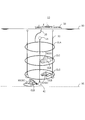
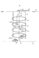
- FIG. 1 is a schematic diagram illustrating an example of an environment in which the power transmission system 10 according to the first embodiment is placed.
- the power transmission system 10 includes a power transmission device 100, a power reception device 200, and a coil CL (see FIG. 2).
- the power transmission device 100 transmits power to the power reception device 200 wirelessly (contactlessly) according to the magnetic resonance method via the plurality of coils CL.
- the number of coils CL to be arranged is n and is arbitrary.
- the coil CL is formed, for example, in an annular shape, and is covered with a resin cover to be insulated.
- the coil CL is, for example, a helical coil or a spiral coil.
- the coil CL is formed of, for example, a cabtyre cable.
- the coil CL includes a power transmission coil CLA and a power reception coil CLB.
- the power transmission coil CLA is a primary coil
- the power reception coil CLB is a secondary coil.
- the coil CL may include one or more relay coils CLC (Booster Coil) disposed between the power transmission coil CLA and the power reception coil CLB.
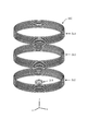
- the relay coils CLC are arranged substantially in parallel, and more than half of the opening surfaces formed by the relay coils CLC overlap. The interval between the plurality of relay coils CLC is ensured, for example, equal to or greater than the radius of the relay coil CLC.
- the relay coil CLC assists power transmission by the power transmission coil CLA.
- the power transmission coil CLA is provided in the power transmission device 100.
- the power receiving coil CLB is provided in the power receiving device 200.
- the relay coil CLC may be provided in the power transmission device 100, the power reception device 200, or provided separately from the power transmission device 100 and the power reception device 200. A part of the relay coil CLC may be provided in the power transmission device 100, and the other part may be provided in the power reception device 200.
- the power transmission device 100 is installed in the ship 50.
- the power receiving device 200 is installed in a movable underwater vehicle 60 (for example, a submersible craft 70 or a submarine excavator 80) or a fixed power receiving device (for example, a seismometer, a monitoring camera, or a geothermal generator).
- Each coil CL is disposed in water (for example, in the sea).
- the submersible 70 may be, for example, a remotely operated unmanned explorer (ROV), an unmanned underwater vehicle (UUV), or a self-sustained unmanned submersible (AUV: Autonomous).
- ROV remotely operated unmanned explorer
- UUV unmanned underwater vehicle
- UUV unmanned underwater vehicle
- AUV self-sustained unmanned submersible
- a part of the ship 50 exists above the water surface 90 (for example, the sea surface), that is, on the water, and another part of the ship 50 exists below the water surface 90, that is, in the water.
- the ship 50 can move on the water, for example, can move freely on the water of the data acquisition location.
- the power transmission device 100 of the ship 50 and the power transmission coil CLA are connected by the electric wire 20.
- the electric wire 20 is connected to, for example, a driver 151 (see FIG. 2) in the power transmission device 100 via a water connector.
- the underwater vehicle 60 exists underwater or at the bottom 95 (for example, the seabed) and travels underwater or the bottom 95. For example, it is possible to move freely to the data acquisition point according to an instruction from the ship 50 on the water.
- the instruction from the ship 50 may be transmitted by communication via each coil CL, or may be transmitted by other communication methods.
- Each coil CL is connected to the coupling body 30 and is arranged at equal intervals, for example.
- the distance between adjacent coils CL (coil interval) is, for example, 5 m.
- the coil interval is, for example, about half the diameter of the coil CL.
- the transmission frequency is, for example, 40 kHz or less and preferably less than 10 kHz in consideration of the attenuation amount of the magnetic field strength in water or in the sea.
- the transmission frequency is less than 10 kHz.
- the transmission frequency is determined based on coil characteristics such as the inductance of the coil CL, the diameter of the coil CL, and the number of turns of the coil CL.
- the diameter of the coil CL is, for example, several meters to several tens of meters. Further, the thicker the coil CL, that is, the larger the wire diameter of the coil CL, the lower the electric resistance in the coil CL and the smaller the power loss.
- the power transmitted through the coil CL is, for example, 50 W or more, and may be on the kW order.
- the number of the linked bodies 30 is three, but is not limited thereto.
- a weight 40 is connected to the end of the coupling body 30 on the power receiving coil CLB side.
- a buoy 45 is connected to the end of the coupling body 30 on the power transmission coil CLA side.
- the movement of the connection body 30 can be restricted by the weight 40, and the movement of each coil CL fixed to the connection body 30 can be restricted. Therefore, even if a water flow occurs in the water, the movement of each coil CL is restricted by the weight 40, so that it is possible to suppress a reduction in the efficiency of power transmission using the coil CL.
- the weight 40 is connected to the end on the power receiving coil CLB side, and the buoy 45 is connected to the end on the power transmission coil CLA side, so that the weight 40 becomes the water bottom side and the buoy 45 becomes the water surface side.
- the posture in which the connecting body 30 is substantially perpendicular to the water surface 90 can be maintained. Therefore, the surface defined by each coil CL is substantially parallel to the water surface 90, and power can be transmitted in the water depth direction (direction substantially orthogonal to the water surface) by the magnetic field resonance method.
- the weight 40 may be detached from the connection body 30 when the connection body 30 is transported, and the weight 40 may be attached to the connection body 30 when the transport of the connection body 30 is completed and installed at a predetermined position. . Thereby, conveyance of the connection body 30 becomes easy.
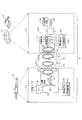
- FIG. 2 is a block diagram illustrating a configuration example of the power transmission system 10.
- the power transmission system 10 includes a power transmission device 100 and a power reception device 200.
- the power transmission apparatus 100 includes a power source 110, an ADC (AC / DC Converter) 120, a CPU (Central Processing Unit) 130, an information communication unit 140, and a power transmission circuit 150.
- ADC AC / DC Converter
- CPU Central Processing Unit
- the ADC 120 converts AC power supplied from the power source 110 into DC power.
- the converted DC power is sent to the power transmission circuit 150.
- the CPU 130 controls the operation of each unit (for example, the power supply 110, the ADC 120, the information communication unit 140, and the power transmission circuit 150) of the power transmission device 100.
- the information communication unit 140 includes a modulation / demodulation circuit 141 for modulating or demodulating communication data communicated with the power receiving apparatus 200.
- the information communication unit 140 transmits control information from the power transmission apparatus 100 to the power reception apparatus 200 via the coil CL.
- the information communication unit 140 receives data from the power receiving device 200 to the power transmitting device 100 via the coil CL.
- This data includes, for example, search result data obtained by underwater exploration or bottom exploration by the power receiving device 200.
- the information communication unit 140 allows the underwater vehicle 60 to quickly perform data communication with the underwater vehicle 60 while performing operations such as data collection.
- the power transmission circuit 150 includes a driver 151 and a resonance circuit 152.
- the driver 151 converts the DC power from the ADC 120 into an AC voltage (pulse waveform) having a predetermined frequency.
- the resonance circuit 152 includes a capacitor CA and a power transmission coil CLA, and generates an AC voltage with a sine wave waveform from an AC voltage with a pulse waveform from the driver 151.
- the power transmission coil CLA resonates at a predetermined resonance frequency according to the AC voltage applied from the driver 151.
- the power transmission coil CLA is impedance matched to the output impedance of the power transmission device 100.
- the predetermined frequency related to the AC voltage obtained by the conversion by the driver 151 corresponds to the transmission frequency of power transmission between the power transmission device 100 and the power reception device 200 and corresponds to the resonance frequency.
- this transmission frequency is set based on the Q value of each coil CL. Details of the set transmission frequency will be described later.
- the power receiving apparatus 200 includes a power receiving circuit 210, a CPU 220, a charge control circuit 230, a secondary battery 240, and an information communication unit 250.
- the power receiving circuit 210 includes a rectifier circuit 211, a regulator 212, and a resonance circuit 213.
- the resonance circuit 213 includes a capacitor CB and a power reception coil CLB, and receives AC power transmitted from the power transmission coil CLA.
- the power receiving coil CLB is impedance matched to the input impedance of the power receiving device 200.
- the rectifier circuit 211 converts AC power induced in the power receiving coil CLB into DC power.
- the regulator 212 converts the DC voltage sent from the rectifier circuit 211 into a predetermined voltage that is suitable for charging the secondary battery 240.
- the CPU 220 controls the operation of each unit of the power receiving device 200 (for example, the power receiving circuit 210, the charging control circuit 230, the secondary battery 240, and the information communication unit 250).
- the charging control circuit 230 controls charging to the secondary battery 240 according to the type of the secondary battery 240. For example, when the secondary battery 240 is a lithium ion battery, the charging control circuit 230 starts charging the secondary battery 240 with a constant voltage and DC power from the regulator 212.
- the secondary battery 240 stores the electric power transmitted from the power transmission device 100.
- the secondary battery 240 is, for example, a lithium ion battery.
- the information communication unit 250 includes a modulation / demodulation circuit 251 for modulating or demodulating communication data communicated with the power transmission device 100.
- the information communication unit 250 receives control information from the power transmission device 100 to the power reception device 200 via the coil CL.
- the information communication unit 250 transmits data from the power receiving device 200 to the power transmitting device 100 via the coil CL.
- This data includes, for example, search result data obtained by underwater exploration or bottom exploration by the power receiving device 200.
- the information communication unit 250 allows the underwater vehicle 60 to quickly perform data communication with the ship 50 while performing operations such as data collection.
- the relay coil CLC forms a resonance circuit together with the capacitor CC, like the power transmission coil CLA and the power reception coil CLB. That is, in this embodiment, electric power is transmitted by the magnetic resonance method by arranging the resonance circuits in multiple stages in water.
- the resonance circuit 152 when a current flows through the power transmission coil CLA of the power transmission device 100, a magnetic field is generated around the power transmission coil CLA.
- the generated vibration of the magnetic field is transmitted to a resonance circuit including a relay coil CLC that resonates at the same frequency or a resonance circuit 213 including a power receiving coil CLB.
- a current is excited in the relay coil CLC due to the vibration of the magnetic field, a current flows, and a magnetic field is further generated around the relay coil CLC.
- the generated vibration of the magnetic field is transmitted to a resonance circuit including another relay coil CLC that resonates at the same frequency or a resonance circuit 213 including a power receiving coil CLB.
- an alternating current is induced in the power receiving coil CLB by the vibration of the magnetic field of the relay coil CLC or the power transmitting coil CLA.
- the induced alternating current is rectified, converted into a predetermined voltage, and the secondary battery 240 is charged.
- FIG. 3 is a schematic diagram showing an example of a simulation model 300 used for the first simulation.
- the simulation model 300 includes a power transmission coil CL ⁇ and a power receiving coil CLB.
- the power transmission coil CL ⁇ is a coil used for power transmission, and includes, for example, a power transmission coil CLA and a relay coil CLC.
- the simulation model 300 is placed in the sea and simulated.
- the y direction is a direction orthogonal to the water surface 90 and is a direction in which power is transmitted.
- the xz plane is parallel to the water surface 90.
- the number of turns of the relay coil CLC) is 10, and the wire diameter of the power transmission coil CL ⁇ (power transmission coil CLA, relay coil CLC) is 9.1 mm. That is, the coil characteristics of the power transmission coil CLA and the relay coil CLC are the same. Therefore, the power transmission coil CLA and the relay coil CLC have, for example, the same frequency characteristics of the Q value.
- the number of turns of the power receiving coil CLB is 23, and the wire diameter of the power receiving coil CLB is 2.0 mm.
- the power receiving coil CLB is often mounted on various devices (for example, an underwater vehicle 60 described later). Therefore, the diameter of the power receiving coil CLB is often smaller than the diameters of the power transmitting coil CLA and the relay coil CLC for power transmission. When the diameter of the power receiving coil CLB is reduced, the inductance (L) of the coil is reduced. In comparison with the power transmission coil CL ⁇ , the power receiving coil CLB is often increased in the number of turns of the coil in order to suppress a decrease in inductance.
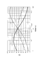
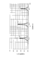
- FIG. 4 is a graph showing an example of the frequency characteristic of the Q value of each coil when the simulation model 300 is used.
- the horizontal axis in FIG. 4 indicates the frequency, and the vertical axis indicates the Q value.
- FIG. 4 shows a frequency characteristic L11 of the Q value of the power transmission coil CL ⁇ , a frequency characteristic L12 of the Q value of the power receiving coil CLB, and a frequency characteristic L13 of a virtual Q value described later.
- the Q value represents the sharpness of the resonance peak of the resonance circuit. Therefore, the transmission efficiency by the coil CL improves as the Q value increases.
- the Q value is represented by the following (Equation 1).
- the angular frequency ⁇ is expressed by the following (Equation 2) when the inductance component L and the capacitance component C are used.
- the virtual Q value indicated by the frequency characteristic L13 in FIG. 4 is derived based on the Q value of the power transmission coil CL ⁇ and the Q value of the power receiving coil CLB.
- Q3 is expressed by the following (formula 3).
- Q3 as the virtual Q value is calculated based on, for example, Q1 and Q2 for each frequency, and the frequency characteristic L13 is derived.
- Q3 is the geometric mean value of Q1 and Q2.
- a frequency fcp1 (for example, a frequency of 11 kHz) serving as an intersection (cross point) between the frequency characteristics L11 and L12, that is, in the vicinity of the frequency fcp1 where Q1 and Q2 are the same value. It can be understood that there is a maximum Q value at the position of the frequency fq13 (for example, the frequency of 12.3 kHz). Note that the specific Q value depends on the coil characteristics of the coil CL (each parameter related to the coil CL).
- the power transmission coil CL ⁇ has a larger coil diameter than the power receiving coil CLB. For this reason, the power transmission coil CL ⁇ has an inductance (L) larger than that of the power receiving coil CLB. Therefore, according to (Equation 2), the angular frequency ⁇ of the power transmission coil CL ⁇ is smaller than that of the power reception coil CLB. Therefore, the frequency fq11 at which the Q value of the power transmission coil CL ⁇ is maximum is the Q value of the power reception coil CLB. Becomes lower than the maximum frequency fq12.
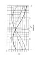
- FIG. 5 is a graph showing an example of frequency characteristics of transmission efficiency of each coil when the simulation model 300 is used.
- the horizontal axis in FIG. 5 indicates the frequency, and the vertical axis indicates the current or voltage transmission efficiency.
- This transmission characteristic indicates the ratio of the received power of the power receiving coil CLB to the transmission power of the power transmitting coil CLA, and corresponds to the S21 parameter.
- a peak value P11 for example, a value of 0.46 of transmission efficiency appears at the position of the frequency fq11 corresponding to the maximum value of Q1.
- a peak value P12 for example, a value of 0.38) of transmission efficiency appears at the position of the frequency fq12 corresponding to the maximum value of Q2.
- a peak value P13 of transmission efficiency (for example, a value of 0.57) appears at the position of the frequency fq13 corresponding to the maximum value of Q3.
- transmission efficiency becomes high, so that Q value is large, and transmission of electric power energy becomes inadequate when Q value is smaller than fixed value, and electric power transmission becomes difficult.
- the transmission efficiency ⁇ of power is derived by squaring the transmission efficiency on the vertical axis in FIG.
- the power transmission efficiency ⁇ at the frequency fq11 is 21.3%.
- the power transmission efficiency ⁇ at the frequency fq12 is 14.8%.
- the power transmission efficiency ⁇ at the frequency fq13 is 32.8%.
- the frequency at which the transmission efficiency ⁇ increases (for example, becomes the maximum) by deriving the geometric mean of the Q values of the coils. Can be derived.
- a CPU of a simulation apparatus for example, a PC (Personal Computer)
- a CPU 130 of the power transmission apparatus 100 for example, a PC (Personal Computer)
- a CPU 220 of the power reception apparatus 200 for example, a PC (Personal Computer)
- the peak value P13 is the maximum among the peak values P11 to P13. Accordingly, by selecting the frequency at which the peak value P13 as the maximum value of the transmission efficiency is obtained, that is, the frequency fq13 derived from the maximum value of the frequency characteristic L13 of Q3, the power transmission system 10 causes the power transmission coil CL ⁇ to It can be understood that the transmission efficiency of the power transmission by the magnetic field resonance method using the power receiving coil CLB can be maximized.
- the position of the frequency fcp1 at the cross point where the frequency characteristic L11 of Q1 and the frequency characteristic L11 of Q2 intersect may be slightly different from the position of the frequency fq13 corresponding to the maximum value of Q3.
- the magnitude of Q3 at the frequency fcp1 is close to the maximum value of Q3 (that is, Q3 at the frequency fq13). Therefore, even when any frequency between the frequency fcp1 and the frequency fq13 is set as the transmission frequency, the transmission efficiency approximate to the peak value P13 can be obtained and the transmission efficiency can be improved.
- FIG. 6 is a schematic diagram showing an example of a simulation model 600 used for the second simulation.
- the simulation model 600 is the same as the simulation model 300 except for the characteristics of the power receiving coil CLB. In the second simulation, the simulation model 600 is placed in the sea and simulated.
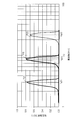
- FIG. 7 is a graph showing an example of the frequency characteristic of the Q value of each coil when the simulation model 600 is used.
- the horizontal axis indicates the frequency
- the vertical axis indicates the Q value.
- FIG. 7 shows a frequency characteristic L21 of the Q value of the power transmission coil CL ⁇ , a frequency characteristic L22 of the Q value of the power receiving coil CLB, and a frequency characteristic L23 of the virtual Q value. Note that the method for deriving Q3 as the virtual Q value is the same as in the first simulation, and Q3 is based on the geometric mean value of Q1 and Q2.
- the maximum value of Q2 is also small.
- the frequency fcp2 for example, frequency 8 kHz
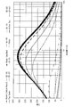
- FIG. 8 is a graph showing an example of frequency characteristics of transmission efficiency of each coil when the simulation model 600 is used.
- the horizontal axis in FIG. 5 indicates the frequency, and the vertical axis indicates the current or voltage transmission efficiency.
- This transmission characteristic indicates the ratio of the received power of the power receiving coil CLB to the transmitted power of the power transmitting coil CLA, as in the first simulation, and corresponds to the S21 parameter.
- a peak value P21 of transmission efficiency (for example, a value of 0.76) appears at the position of the frequency fq21 corresponding to the maximum value of Q1.
- a peak value P22 (for example, a value of 0.70) of transmission efficiency appears at the position of the frequency fq22 corresponding to the maximum value of Q2.
- a transmission efficiency peak value P23 (for example, a value of 0.78) appears at the position of the frequency fq23 corresponding to the maximum value of Q3.
- the power transmission efficiency ⁇ at the frequency fq21 is 58.3%.
- the power transmission efficiency ⁇ at the frequency fq22 is 48.5%.
- the power transmission efficiency ⁇ at the frequency fq23 is 61.6%.
- the peak value P23 is the maximum among the peak values P21 to P23. Therefore, by selecting the frequency fq23 derived from the maximum value of the frequency characteristic L23 of Q3, that is, the frequency at which the peak value P23 as the maximum value of transmission efficiency is obtained, the power transmission coil CL ⁇ and the power receiving coil CLB are used. It can be understood that the transmission efficiency of power transmission by the magnetic field resonance method can be maximized.
- the position of the frequency fcp2 at the cross point where the frequency characteristic L21 of Q1 and the frequency characteristic L22 of Q2 intersect may be slightly different from the position of the frequency fq23 corresponding to the maximum value of Q3.
- the magnitude of Q3 at the frequency fcp2 is close to the maximum value of Q3 (that is, Q3 at the frequency fq23). Therefore, even when any frequency between the frequency fcp2 and the frequency fq23 is set as the transmission frequency, the transmission efficiency approximate to the peak value P23 is obtained, and the transmission efficiency can be improved.
- FIG. 9 is a graph showing an example of frequency characteristics of the Q value of the coil CL for each medium in which the coil CL is arranged. Since the conductivity differs for each medium, FIG. 9 can also be said to be a graph showing the frequency characteristics of the Q value of the coil CL for each conductivity.
- a medium Debye model water “Water (Debye Model)”, distilled water “Water (distilled)”, normal water (for example, tap water) “Water”, seawater “Water_sea”, and other media are used. included.
- the frequency characteristics of the Debye model for water, distilled water, normal water, and seawater are the default material characteristics attached to the simulator (apparatus for simulating the frequency characteristics of the Q value of the coil CL for each medium). It was obtained.
- the frequency characteristic regarding the tap water measured with the conductivity meter is shown as “Tap Water”.
- the diameter of the coil CL was 4.0 m
- the wire diameter of the coil was 23.6 mm
- the number of turns of the coil was 5.
- the frequency characteristic of the Q value of the coil CL differs for each medium. Therefore, in the first simulation and the second simulation described above, it can be understood that, for example, when the simulation is performed underwater instead of in the sea, the Q value obtained is changed and the Q value is increased.
- the power transmission device 100 transmits power to the power reception device 200 having the power reception coil CLB in water.
- Power transmission device 100 power transmission coil CLA that transmits power to power reception coil CLB via a magnetic field, and driver 151 that transmits AC power of a predetermined frequency (for example, 11 kHz to 12.3 kHz, 8 kHz to 8.5 kHz) to power transmission coil CLA
- a capacitor CA that is connected to the power transmission coil CLA and forms a resonance circuit 152 that resonates with the power transmission coil CLA.
- the predetermined frequencies are frequencies fq13 and fq23 at which the geometric mean value (for example, Q3) of the Q value (for example, Q1) of the power transmission coil CLA and the Q value (for example, Q2) of the power reception coil CLB and the Q value of the power transmission coil CLA. And the frequencies fcp1 and fcp2 at which the Q values of the power receiving coils are the same.
- the driver 151 is an example of a power transmission unit.
- the capacitor CA is an example of a first capacitor.
- Q1 is an example of the Q value of the power transmission coil CLA.
- Q2 is an example of the Q value of the power receiving coil CLB.
- Q3 is an example of a geometric mean value of Q1 and Q2, that is, a virtual Q value derived by (Expression 2).
- the frequencies fq13 and fq23 are an example of the first frequency.
- the frequencies fcp1 and fcp2 are an example of the second frequency.
- the power transmission apparatus 100 determines the frequency (transmission frequency) for power transmission by taking into consideration the geometric mean of both the Q value of the power transmission coil CLA and the Q value of the power reception coil CLB, thereby transmitting power transmission. Efficiency can be improved.
- the transmission frequency the transmission efficiency of the coil of the power transmission coil CLA can be increased, but the transmission efficiency of the power reception coil CLB is decreased.
- the frequency at which the Q value of the power receiving coil CLB is near the maximum value is the transmission frequency
- the transmission efficiency of the coil of the power receiving coil CLB can be increased, but the transmission efficiency by the power transmitting coil CLA is decreased. That is, a suitable transmission frequency differs between the power transmission side and the power reception side.
- the power transmission apparatus 100 uses a plurality of coils by setting a frequency in the vicinity where the average value (synergistic average value) of the Q value of the power transmission coil CLA and the Q value of the power receiving coil CLB is the maximum as the transmission frequency.
- the transmission efficiency of the power transmission system 10 as a whole can be improved by taking into account the Q values of different CL.
- the predetermined frequencies may be frequencies fq13 and fq23.
- the power transmission device 100 is connected to the relay coil CLC with at least one relay coil CLC that transmits power to the power reception coil CLB using the magnetic field from the power transmission coil CLA, and resonates at the above frequency together with the relay coil CLC.
- You may provide at least 1 capacitor
- the frequency characteristic of the Q value of the relay coil CLC may be the same as the frequency characteristic of the Q value of the power transmission coil CLA.
- the capacitor CC is an example of a second capacitor.
- the power transmission device 100 has the same Q value for the power transmission coil CLA and the Q value for the relay coil CLC, so that the power transmission coil CLA and the relay coil CLC have the same characteristics related to power transmission. Transmission loss between the two can be reduced. Further, in the power transmission device 100, since the frequency near the maximum value (the geometric mean value) of the Q value of the relay coil CLC and the Q value of the power receiving coil CLB is the transmission frequency, the relay coil CLC and the power receiving coil Transmission loss with the CLB can also be reduced.
- the power transmission coil CLA may transmit power in a direction substantially orthogonal to the water surface 90.
- the power transmission device 100 can extend the power transmission distance in the water depth direction, can supply power to the power reception device 200 located in a deep water location (for example, deep sea), and can improve the work efficiency of the power reception device 200.
- the power transmission coil CLA may transmit power and communicate data.
- the power receiving apparatus 200 can charge the power from the power transmission apparatus 100 while suppressing a decrease in activity efficiency such as data collection, and can perform data communication with the power transmission apparatus 100.
- the power reception device 200 (for example, the underwater vehicle 60) does not need to contact the power transmission coil CLA even in an environment where there is a flow of water, and the power by the magnetic resonance method. A reduction in transmission efficiency can be suppressed and power can be stably supplied. Therefore, the underwater vehicle 60 can receive continuous power supply while performing activities such as data collection, and the operating rate of the underwater vehicle 60 when receiving power supply is improved. Therefore, the power transmission device 100 can improve the efficiency of data collection activities in water.
- the power transmission device 100 can transmit power wirelessly by the magnetic resonance method by using the power transmission coil CLA of the power transmission device 100 and the power reception coil CLB of the power reception device 200. Moreover, since the underwater vehicle 60 can receive power without moving the underwater vehicle 60 to a predetermined power supply location, the underwater vehicle 60 can move freely even during power supply, and position-free power transmission is possible. It becomes. Therefore, the power transmission device 100 can suppress the activity of the underwater vehicle 60 underwater or at the bottom 95 from being inhibited. Therefore, the underwater vehicle 60 can expand the work range even during charging, and can be continuously charged during work. Moreover, since the underwater vehicle 60 can be charged at an arbitrary timing, the working time can be shortened.
- the power transmission device 100 can extend the power transmission distance by continuous electromagnetic induction by using the relay coil CLC. For example, as illustrated in FIG. 1, by arranging the relay coils CLC in multiple stages from the vicinity of the water surface 90 toward the bottom of the water, the power transmission device 100 can transmit power to a deep water position (for example, a water depth of 1000 m or more). In this case, the power transmission device 100 can wirelessly transmit power to the underwater vehicle 60 that performs mining and investigation of the seabed resources, and can suppress a decrease in the operating rate of the underwater vehicle 60 during power feeding.
- a deep water position for example, a water depth of 1000 m or more.
- the power transmission device 100 can wirelessly transmit power to the underwater vehicle 60 that performs mining and investigation of the seabed resources, and can suppress a decrease in the operating rate of the underwater vehicle 60 during power feeding.
- the underwater vehicle 60 can be active. In this case, the underwater vehicle 60 can be reduced in size and weight.
- the first embodiment has been described as an example of the technique in the present disclosure.
- the technology in the present disclosure is not limited to this, and can also be applied to embodiments in which changes, replacements, additions, omissions, and the like are performed.
- the power transmission system 10 may include the reflection coil CLR as one of the power transmission coils CL ⁇ .
- the reflection coil CLR is disposed between the power transmission coil CLA and the water surface 90.
- the reflection coil CLR reflects the magnetic field emitted from the power transmission coil CLA toward the water surface 90 toward the water bottom 95.
- FIG. 10 is a schematic diagram showing an example of an environment where the power transmission system 10 provided with the reflection coil CLR is placed.
- the power transmission system 10 can suppress interference between the magnetic field emitted from the power transmission coil CLA and the communication of the ultra-long wave (VLF) band or the ultra-long wave (ULF) on or in water. Therefore, the power transmission system 10 can improve the transmission efficiency of the power transmitted from the power transmission coil to the power reception coil by providing the reflection coil CLR.
- VLF ultra-long wave
- ULF ultra-long wave
- the reflection coil CLR is not connected to a capacitor like the power reception coil CLB and the relay coil CLC, and does not form a resonance circuit. That is, the reflection coil CLR is a closed loop without a capacitor.
- a second reflection coil having a smaller coil diameter than the reflection coil CLR may be arranged inside the reflection coil CLR shown in FIG. 10 concentrically with the reflection coil CLR.
- the underwater vehicle 60 includes the secondary battery 240, so that underwater charging is possible.
- the underwater vehicle 60 may not include the secondary battery 240. Even in this case, the underwater vehicle 60 can be supplied with electric power through each coil CL, that is, can be supplied with water underwater.
- the power transmission system 10 is exemplified by a submarine camera system that collects data in the sea or at the bottom of the sea, but may be applied to other uses.
- the power receiving device 200 may be provided in an underwater robot or an unmanned explorer equipped with various sensors, and may be disposed in the water or in the bottom 95. This makes it possible to manage marine resources and aquaculture, maintain and manage infrastructure systems such as bridges and dams, and monitor the seabed of harbors, etc., using underwater robots and unmanned explorers.
- the power transmission coil CLA, the relay coil CLC, and the power reception coil CLB are arranged side by side from the water surface 90 toward the water bottom 95, but the arrangement direction of the coil CL is limited to this. Absent.
- the power transmission coil CLA, the relay coil CLC, and the power reception coil CLB may be arranged side by side in the direction along the water surface 90 or the water bottom 95. Thereby, the power transmission apparatus 100 can transmit electric power horizontally in water.
- the power transmission coil CLA, the relay coil CLC, and the power reception coil CLB are arranged side by side from the water surface 90 toward the water bottom 95, but this may be reversed. That is, the power transmission coil CLA, the relay coil CLC, and the power reception coil CLB may be arranged side by side from the water bottom 95 toward the water surface 90.
- a geothermal power generator may be used as the power source 110 of the power transmission apparatus 100 and the geothermal power generator may be connected to the power transmission coil CLA via the electric wire 20.
- the power transmission device 100 may not be installed on the ship 50.
- various generators for example, solar power generator, wind power generator, wave power generator
- various generators geothermal generators
- a part of the power transmission device 100 may be mounted.
- various generators may be used as the power source 110 of the power transmission device 100.
- the CPUs 130 and 220 are exemplified, but a processor other than the CPUs 130 and 220 may be used.
- the processor may be physically configured in any manner. Further, if a programmable processor is used, the processing contents can be changed by changing the program, so that the degree of freedom in designing the processor can be increased.
- the processor may be composed of one semiconductor chip or physically composed of a plurality of semiconductor chips. When configured by a plurality of semiconductor chips, each control of the first embodiment may be realized by separate semiconductor chips. In this case, it can be considered that a plurality of semiconductor chips constitute one processor.
- the processor may be configured by a member (capacitor or the like) having a function different from that of the semiconductor chip. Further, one semiconductor chip may be configured so as to realize the functions of the processor and other functions.
- This disclosure is useful for a power transmission device that can improve the transmission efficiency of non-contact power transmission to a power receiving device in water.
Abstract
Provided is a power transmission device that can improve the transmission efficiency of contactless power transmission to a power reception device in water. The power transmission device transmits power, in water, to the power reception device which has a power reception coil. The power transmission device comprises: a power transmission coil that transmits power to the power reception coil via a magnetic field; a power transmission unit that transmits alternating-current power of a prescribed frequency to the power transmission coil; and a first capacitor that is connected to the power transmission coil and forms a resonant circuit that resonates with the power transmission coil. The prescribed frequency is any frequency between a first frequency at which the geometrical mean value of the Q value of the power transmission coil and the Q value of the power reception coil is maximum, and a second frequency at which the Q value of the power transmission coil and the Q value of the power reception coil have the same value.
Description
本開示は、水中において無線で送電する送電装置に関する。
The present disclosure relates to a power transmission device that wirelessly transmits power in water.
従来、送電装置としての水中基地局が、受電装置としての水中航走体との間で、磁気共鳴方式を用いて非接触で電力伝送することが知られている(例えば特許文献1参照)。この送電装置は、送電用共鳴コイルと、風船と、風船制御機構と、を具備する。送電用共鳴コイルは、磁界共鳴方式により受電装置の受電用共鳴コイルに非接触で電力伝送する。風船は、送電用共鳴コイルを内包する。風船制御機構は、風船を電力伝送時に膨張させることにより、送電用共鳴コイルと受電用共鳴コイルとの間の水を排除する。
Conventionally, it is known that an underwater base station as a power transmission device transmits power in a contactless manner with an underwater vehicle as a power receiving device using a magnetic resonance method (see, for example, Patent Document 1). The power transmission device includes a power transmission resonance coil, a balloon, and a balloon control mechanism. The power transmission resonance coil transmits power in a non-contact manner to the power reception resonance coil of the power receiving device by a magnetic field resonance method. The balloon contains a power transmission resonance coil. The balloon control mechanism removes water between the power transmission resonance coil and the power reception resonance coil by expanding the balloon during power transmission.
また、13.56MHz帯の周波数を用いる電磁誘導方式を利用して、電力とデータをIC搭載媒体に送信するアンテナ装置が知られている(例えば特許文献2参照)。このアンテナ装置は、信号電流が給電される少なくとも1つの給電ループアンテナと信号電流が給電されない少なくとも1つの無給電ループアンテナを有し、給電ループアンテナが発生する磁界を利用して無給電ループアンテナにも信号電流を発生させ、給電ループアンテナの通信範囲を拡大させる点を開示している。
In addition, an antenna device that transmits power and data to an IC-mounted medium using an electromagnetic induction method using a frequency of 13.56 MHz band is known (see, for example, Patent Document 2). This antenna apparatus has at least one feeding loop antenna to which a signal current is fed and at least one parasitic loop antenna to which no signal current is fed, and uses the magnetic field generated by the feeding loop antenna as a parasitic loop antenna. Also discloses that a signal current is generated and the communication range of the feed loop antenna is expanded.
磁界共鳴方式による電力伝送の伝送効率を表す1つの指標として、電力伝送に用いられるコイルのQ値(Quality factor)がある。磁界共鳴方式による電力伝送には、少なくとも送電用共鳴コイルと受電用共鳴コイルを含む複数のコイルが用いられる。複数のコイルは、大きさ、材質、長さ、巻き数などの特性(コイル特性)が異なることがある。コイルのQ値は、コイル特性に応じて異なる。そのため、1つのコイルのコイル特性に合わせたQ値が得られる周波数が、電力伝送に用いられる周波数(伝送周波数)として設定されると、電力伝送の伝送効率が低下する虞がある。
As one index representing the transmission efficiency of power transmission by the magnetic field resonance method, there is a Q factor (Quality factor) of a coil used for power transmission. A plurality of coils including at least a power transmission resonance coil and a power reception resonance coil are used for power transmission by the magnetic field resonance method. The plurality of coils may have different characteristics (coil characteristics) such as size, material, length, and number of turns. The Q value of the coil varies depending on the coil characteristics. For this reason, if a frequency at which a Q value that matches the coil characteristics of one coil is set as a frequency (transmission frequency) used for power transmission, the transmission efficiency of power transmission may be reduced.
本開示は、上記事情に鑑みてなされたものであり、水中における受電装置への非接触電力伝送の伝送効率を向上できる送電装置を提供する。
This disclosure has been made in view of the above circumstances, and provides a power transmission device that can improve the transmission efficiency of non-contact power transmission to a power receiving device in water.
本開示の送電装置は、水中において、受電コイルを有する受電装置に電力を伝送する。送電装置は、磁界を介して受電コイルに電力を伝送する送電コイルと、所定の周波数の交流電力を送電コイルへ送電する送電部と、送電コイルに接続されると共に、送電コイルと共に共振する共振回路を形成する第1のコンデンサと、を備える。上記の所定の周波数は、送電コイルのQ値及び受電コイルのQ値の相乗平均値が最大となる第1の周波数と、送電コイルのQ値及び受電コイルのQ値が同値となる第2の周波数と、の間のいずれかの周波数である。
The power transmission device of the present disclosure transmits power to a power reception device having a power reception coil in water. A power transmission device includes a power transmission coil that transmits power to a power reception coil via a magnetic field, a power transmission unit that transmits AC power of a predetermined frequency to the power transmission coil, and a resonance circuit that is connected to the power transmission coil and resonates with the power transmission coil. And a first capacitor that forms The predetermined frequency is the first frequency at which the geometric mean value of the Q value of the power transmission coil and the Q value of the power reception coil is maximized, and the second frequency at which the Q value of the power transmission coil and the Q value of the power reception coil are the same value. Any frequency between.
本開示によれば、水中における受電装置への非接触電力伝送の伝送効率を向上できる。
According to the present disclosure, it is possible to improve the transmission efficiency of non-contact power transmission to the power receiving device in water.
以下、適宜図面を参照しながら、実施形態を詳細に説明する。但し、必要以上に詳細な説明は省略する場合がある。例えば、既によく知られた事項の詳細説明や実質的に同一の構成に対する重複説明を省略する場合がある。これは、以下の説明が不必要に冗長になることを避け、当業者の理解を容易にするためである。尚、添付図面及び以下の説明は、当業者が本開示を十分に理解するために提供されるものであり、これらにより特許請求の範囲に記載の主題を限定することは意図されていない。
Hereinafter, embodiments will be described in detail with reference to the drawings as appropriate. However, more detailed description than necessary may be omitted. For example, detailed descriptions of already well-known matters and repeated descriptions for substantially the same configuration may be omitted. This is to avoid the following description from becoming unnecessarily redundant and to facilitate understanding by those skilled in the art. The accompanying drawings and the following description are provided to enable those skilled in the art to fully understand the present disclosure, and are not intended to limit the claimed subject matter.
(第1の実施形態)
[構成等]
図1は、第1の実施形態における電力伝送システム10が置かれる環境の一例を示す模式図である。電力伝送システム10は、送電装置100、受電装置200、及びコイルCLを備える(図2参照)。送電装置100は、受電装置200に対して、複数のコイルCLを介して、磁気共鳴方式に従ってワイヤレス(無接点)で電力伝送する。配置されるコイルCLの数は、n個であり、任意である。 (First embodiment)
[Configuration]
FIG. 1 is a schematic diagram illustrating an example of an environment in which thepower transmission system 10 according to the first embodiment is placed. The power transmission system 10 includes a power transmission device 100, a power reception device 200, and a coil CL (see FIG. 2). The power transmission device 100 transmits power to the power reception device 200 wirelessly (contactlessly) according to the magnetic resonance method via the plurality of coils CL. The number of coils CL to be arranged is n and is arbitrary.
[構成等]
図1は、第1の実施形態における電力伝送システム10が置かれる環境の一例を示す模式図である。電力伝送システム10は、送電装置100、受電装置200、及びコイルCLを備える(図2参照)。送電装置100は、受電装置200に対して、複数のコイルCLを介して、磁気共鳴方式に従ってワイヤレス(無接点)で電力伝送する。配置されるコイルCLの数は、n個であり、任意である。 (First embodiment)
[Configuration]
FIG. 1 is a schematic diagram illustrating an example of an environment in which the
コイルCLは、例えば、環状に形成され、樹脂のカバーで被覆されて絶縁されている。コイルCLは、例えば、ヘリカルコイルやスパイラルコイルである。また、コイルCLは、例えばキャプタイヤケーブルで形成される。コイルCLは、送電コイルCLA及び受電コイルCLBを含む。送電コイルCLAは、一次コイル(Primary Coil)であり、受電コイルCLBは、二次コイル(Secondary Coil)である。
The coil CL is formed, for example, in an annular shape, and is covered with a resin cover to be insulated. The coil CL is, for example, a helical coil or a spiral coil. The coil CL is formed of, for example, a cabtyre cable. The coil CL includes a power transmission coil CLA and a power reception coil CLB. The power transmission coil CLA is a primary coil, and the power reception coil CLB is a secondary coil.
また、コイルCLは、送電コイルCLAと受電コイルCLBとの間に配置された1つ以上の中継コイルCLC(Booster Coil)を含んでもよい。中継コイルCLC同志は、略平行に配置され、中継コイルCLCにより形成される開口面の半分以上が重なる。複数の中継コイルCLC間の間隔は、例えば中継コイルCLCの半径以上確保される。中継コイルCLCは、送電コイルCLAによる電力伝送を補助する。
The coil CL may include one or more relay coils CLC (Booster Coil) disposed between the power transmission coil CLA and the power reception coil CLB. The relay coils CLC are arranged substantially in parallel, and more than half of the opening surfaces formed by the relay coils CLC overlap. The interval between the plurality of relay coils CLC is ensured, for example, equal to or greater than the radius of the relay coil CLC. The relay coil CLC assists power transmission by the power transmission coil CLA.
送電コイルCLAは、送電装置100に設けられる。受電コイルCLBは、受電装置200に設けられる。中継コイルCLCは、送電装置100に設けられても、受電装置200に設けられても、送電装置100及び受電装置200とは別に設けられてもよい。中継コイルCLCは、一部が送電装置100に設けられ、他の一部が受電装置200に設けられてもよい。
The power transmission coil CLA is provided in the power transmission device 100. The power receiving coil CLB is provided in the power receiving device 200. The relay coil CLC may be provided in the power transmission device 100, the power reception device 200, or provided separately from the power transmission device 100 and the power reception device 200. A part of the relay coil CLC may be provided in the power transmission device 100, and the other part may be provided in the power reception device 200.
送電装置100は、船舶50に設置される。受電装置200は、移動可能な水中航走体60(例えば潜水艇70や水底掘削機80)や固定的に設置される受電装置(例えば地震計、監視カメラ、地熱発電機)に設置される。各コイルCLは、水中(例えば海中)に配置される。
The power transmission device 100 is installed in the ship 50. The power receiving device 200 is installed in a movable underwater vehicle 60 (for example, a submersible craft 70 or a submarine excavator 80) or a fixed power receiving device (for example, a seismometer, a monitoring camera, or a geothermal generator). Each coil CL is disposed in water (for example, in the sea).
潜水艇70は、例えば、遠隔操作無人探査機(ROV:Remotely Operated Vehicle)、無人潜水艇(UUV:Unmanned Underwater Vehicle)、又は自立型無人潜水機(AUV:Autonomous Underwater Vehicle)を含んでもよい。
The submersible 70 may be, for example, a remotely operated unmanned explorer (ROV), an unmanned underwater vehicle (UUV), or a self-sustained unmanned submersible (AUV: Autonomous).
船舶50の一部は、水面90(例えば海面)より上部つまり水上に存在し、船舶50の他の一部は、水面90よりも下部つまり水中に存在する。船舶50は、水上で移動可能であり、例えばデータ取得場所の水上へ自由に移動可能である。船舶50の送電装置100と送電コイルCLAとの間は、電線20により接続される。電線20は、水上のコネクタを介して、例えば送電装置100内のドライバ151(図2参照)と接続される。
A part of the ship 50 exists above the water surface 90 (for example, the sea surface), that is, on the water, and another part of the ship 50 exists below the water surface 90, that is, in the water. The ship 50 can move on the water, for example, can move freely on the water of the data acquisition location. The power transmission device 100 of the ship 50 and the power transmission coil CLA are connected by the electric wire 20. The electric wire 20 is connected to, for example, a driver 151 (see FIG. 2) in the power transmission device 100 via a water connector.
水中航走体60は、水中又は水底95(例えば海底)に存在し、水中又は水底95を航走する。例えば、水上の船舶50からの指示により、データ取得ポイントへ自由に移動可能である。船舶50からの指示は、各コイルCLを介した通信により伝送されてもよいし、その他の通信方法により伝送されてもよい。
The underwater vehicle 60 exists underwater or at the bottom 95 (for example, the seabed) and travels underwater or the bottom 95. For example, it is possible to move freely to the data acquisition point according to an instruction from the ship 50 on the water. The instruction from the ship 50 may be transmitted by communication via each coil CL, or may be transmitted by other communication methods.
各コイルCLは、連結体30と接続され、例えば等間隔に配置される。隣り合うコイルCL間の距離(コイル間隔)は、例えば5mである。コイル間隔は、例えばコイルCLの直径の半分程度の長さである。伝送周波数は、水中又は海中での磁界強度の減衰量を考慮すると、例えば40kHz以下であり、10kHz未満とされることが好ましい。また、10kHz以上の送信周波数で電力伝送する場合には、電波法の規定に基づいて所定のシミュレーションを行う必要があり、10kHz未満の場合にはこの作業を省略できる。尚、伝送周波数が低周波であるほど、電力伝送距離が長くなり、コイルCLが大きくなり、コイル間隔が長くなる。
Each coil CL is connected to the coupling body 30 and is arranged at equal intervals, for example. The distance between adjacent coils CL (coil interval) is, for example, 5 m. The coil interval is, for example, about half the diameter of the coil CL. The transmission frequency is, for example, 40 kHz or less and preferably less than 10 kHz in consideration of the attenuation amount of the magnetic field strength in water or in the sea. In addition, when power is transmitted at a transmission frequency of 10 kHz or more, it is necessary to perform a predetermined simulation based on the regulations of the Radio Law, and this work can be omitted when the frequency is less than 10 kHz. The lower the transmission frequency, the longer the power transmission distance, the larger the coil CL, and the longer the coil interval.
伝送周波数は、コイルCLのインダクタンス、コイルCLの直径、コイルのCLの巻き数等のコイル特性に基づき定まる。コイルCLの直径は、例えば数m~数10mである。また、コイルCLの太さが太い程、つまりコイルCLの線径が大きい程、コイルCLでの電気抵抗が減り、電力損失が小さくなる。また、コイルCLを介して伝送される電力は、例えば50W以上であり、kWオーダーでもよい。
The transmission frequency is determined based on coil characteristics such as the inductance of the coil CL, the diameter of the coil CL, and the number of turns of the coil CL. The diameter of the coil CL is, for example, several meters to several tens of meters. Further, the thicker the coil CL, that is, the larger the wire diameter of the coil CL, the lower the electric resistance in the coil CL and the smaller the power loss. The power transmitted through the coil CL is, for example, 50 W or more, and may be on the kW order.
図1では、連結体30の数が3つであるが、これに限られない。連結体30における受電コイルCLB側の端部には、錘40が接続される。連結体30における送電コイルCLA側の端部には、ブイ(Buoy)45が接続される。
In FIG. 1, the number of the linked bodies 30 is three, but is not limited thereto. A weight 40 is connected to the end of the coupling body 30 on the power receiving coil CLB side. A buoy 45 is connected to the end of the coupling body 30 on the power transmission coil CLA side.
錘40により、連結体30の移動を規制でき、連結体30に固定された各コイルCLの移動を規制できる。よって、水中において水流が発生しても、錘40により各コイルCLの移動が規制されるので、コイルCLを用いた電力伝送の効率が低下することを抑制できる。
The movement of the connection body 30 can be restricted by the weight 40, and the movement of each coil CL fixed to the connection body 30 can be restricted. Therefore, even if a water flow occurs in the water, the movement of each coil CL is restricted by the weight 40, so that it is possible to suppress a reduction in the efficiency of power transmission using the coil CL.
また、連結体30において、受電コイルCLB側の端部に錘40が接続され、送電コイルCLA側の端部にブイ45が接続されることで、錘40が水底側、ブイ45が水面側となり、連結体30が水面90と略垂直となる姿勢を維持できる。よって、各コイルCLにより定義される面は、水面90と略平行となり、磁界共鳴方式によって水深方向(水面と略直交する方向)に電力伝送できる。
Further, in the coupling body 30, the weight 40 is connected to the end on the power receiving coil CLB side, and the buoy 45 is connected to the end on the power transmission coil CLA side, so that the weight 40 becomes the water bottom side and the buoy 45 becomes the water surface side. Thus, the posture in which the connecting body 30 is substantially perpendicular to the water surface 90 can be maintained. Therefore, the surface defined by each coil CL is substantially parallel to the water surface 90, and power can be transmitted in the water depth direction (direction substantially orthogonal to the water surface) by the magnetic field resonance method.
尚、錘40は、連結体30の運搬時には連結体30から取り外され、連結体30の運搬が終了し、所定の位置に設置される際に、連結体30に錘40が取り付けられてもよい。これにより、連結体30の運搬が容易になる。
The weight 40 may be detached from the connection body 30 when the connection body 30 is transported, and the weight 40 may be attached to the connection body 30 when the transport of the connection body 30 is completed and installed at a predetermined position. . Thereby, conveyance of the connection body 30 becomes easy.
図2は、電力伝送システム10の構成例を示すブロック図である。電力伝送システム10は、送電装置100及び受電装置200を備える。
FIG. 2 is a block diagram illustrating a configuration example of the power transmission system 10. The power transmission system 10 includes a power transmission device 100 and a power reception device 200.
送電装置100は、電源110、ADC(AC/DC Converter)120、CPU(Central Processing Unit)130、情報通信部140、及び送電回路150、を備える。
The power transmission apparatus 100 includes a power source 110, an ADC (AC / DC Converter) 120, a CPU (Central Processing Unit) 130, an information communication unit 140, and a power transmission circuit 150.
ADC120は、電源110から供給される交流電力を直流電力に変換する。変換された直流電力は、送電回路150へ送られる。
The ADC 120 converts AC power supplied from the power source 110 into DC power. The converted DC power is sent to the power transmission circuit 150.
CPU130は、送電装置100の各部(例えば電源110、ADC120、情報通信部140、送電回路150)の動作を統括する。
The CPU 130 controls the operation of each unit (for example, the power supply 110, the ADC 120, the information communication unit 140, and the power transmission circuit 150) of the power transmission device 100.
情報通信部140は、受電装置200との間で通信される通信データを変調又は復調するための変復調回路141を含む。情報通信部140は、例えば、送電装置100から受電装置200への制御情報を、コイルCLを介して送信する。情報通信部140は、例えば、受電装置200から送電装置100へのデータを、コイルCLを介して受信する。このデータは、例えば、受電装置200により水中探査や水底探査された探査結果のデータが含まれる。情報通信部140により、水中航走体60がデータ収集等の作業しながら、水中航走体60との間で迅速にデータ通信できる。
The information communication unit 140 includes a modulation / demodulation circuit 141 for modulating or demodulating communication data communicated with the power receiving apparatus 200. For example, the information communication unit 140 transmits control information from the power transmission apparatus 100 to the power reception apparatus 200 via the coil CL. For example, the information communication unit 140 receives data from the power receiving device 200 to the power transmitting device 100 via the coil CL. This data includes, for example, search result data obtained by underwater exploration or bottom exploration by the power receiving device 200. The information communication unit 140 allows the underwater vehicle 60 to quickly perform data communication with the underwater vehicle 60 while performing operations such as data collection.
送電回路150は、ドライバ151及び共振回路152を含む。ドライバ151は、ADC120からの直流電力を所定の周波数の交流電圧(パルス波形)に変換する。共振回路152は、コンデンサCAと送電コイルCLAとを含んで構成され、ドライバ151からのパルス波形の交流電圧から正弦波波形の交流電圧を生成する。送電コイルCLAは、ドライバ151から印加される交流電圧に応じて、所定の共振周波数で共振する。尚、送電コイルCLAは、送電装置100の出力インピーダンスにインピーダンス整合される。
The power transmission circuit 150 includes a driver 151 and a resonance circuit 152. The driver 151 converts the DC power from the ADC 120 into an AC voltage (pulse waveform) having a predetermined frequency. The resonance circuit 152 includes a capacitor CA and a power transmission coil CLA, and generates an AC voltage with a sine wave waveform from an AC voltage with a pulse waveform from the driver 151. The power transmission coil CLA resonates at a predetermined resonance frequency according to the AC voltage applied from the driver 151. The power transmission coil CLA is impedance matched to the output impedance of the power transmission device 100.
尚、ドライバ151が変換することで得られる交流電圧に係る所定の周波数は、送電装置100と受電装置200との間での電力伝送の伝送周波数に相当し、共振周波数に相当する。本実施形態では、この伝送周波数が、各コイルCLのQ値に基づき設定される。設定される伝送周波数の詳細について後述する。
Note that the predetermined frequency related to the AC voltage obtained by the conversion by the driver 151 corresponds to the transmission frequency of power transmission between the power transmission device 100 and the power reception device 200 and corresponds to the resonance frequency. In this embodiment, this transmission frequency is set based on the Q value of each coil CL. Details of the set transmission frequency will be described later.
受電装置200は、受電回路210、CPU220、充電制御回路230、2次電池240、及び情報通信部250を備える。
The power receiving apparatus 200 includes a power receiving circuit 210, a CPU 220, a charge control circuit 230, a secondary battery 240, and an information communication unit 250.
受電回路210は、整流回路211、レギュレータ212、及び共振回路213を含む。共振回路213は、コンデンサCBと受電コイルCLBとを含んで構成され、送電コイルCLAから送電された交流電力を受電する。尚、受電コイルCLBは、受電装置200の入力インピーダンスにインピーダンス整合される。整流回路211は、受電コイルCLBに誘起された交流電力を直流電力に変換する。レギュレータ212は、整流回路211から送られる直流電圧を、2次電池240の充電に適合する所定の電圧に変換する。
The power receiving circuit 210 includes a rectifier circuit 211, a regulator 212, and a resonance circuit 213. The resonance circuit 213 includes a capacitor CB and a power reception coil CLB, and receives AC power transmitted from the power transmission coil CLA. The power receiving coil CLB is impedance matched to the input impedance of the power receiving device 200. The rectifier circuit 211 converts AC power induced in the power receiving coil CLB into DC power. The regulator 212 converts the DC voltage sent from the rectifier circuit 211 into a predetermined voltage that is suitable for charging the secondary battery 240.
CPU220は、受電装置200の各部(例えば受電回路210、充電制御回路230、2次電池240、情報通信部250)の動作を統括する。
The CPU 220 controls the operation of each unit of the power receiving device 200 (for example, the power receiving circuit 210, the charging control circuit 230, the secondary battery 240, and the information communication unit 250).
充電制御回路230は、2次電池240の種別に応じて2次電池240への充電を制御する。例えば、2次電池240がリチウムイオン電池の場合、充電制御回路230は、定電圧で、レギュレータ212からの直流電力により2次電池240への充電を開始する。
The charging control circuit 230 controls charging to the secondary battery 240 according to the type of the secondary battery 240. For example, when the secondary battery 240 is a lithium ion battery, the charging control circuit 230 starts charging the secondary battery 240 with a constant voltage and DC power from the regulator 212.
2次電池240は、送電装置100から伝送された電力を蓄積する。2次電池240は、例えばリチウムイオン電池である。
The secondary battery 240 stores the electric power transmitted from the power transmission device 100. The secondary battery 240 is, for example, a lithium ion battery.
情報通信部250は、送電装置100との間で通信される通信データを変調又は復調するための変復調回路251を含む。情報通信部250は、例えば、送電装置100から受電装置200への制御情報を、コイルCLを介して受信する。情報通信部250は、例えば、受電装置200から送電装置100へのデータを、コイルCLを介して送信する。このデータは、例えば、受電装置200により水中探査や水底探査された探査結果のデータが含まれる。情報通信部250により、水中航走体60がデータ収集等の作業しながら、船舶50との間で迅速にデータ通信できる。
The information communication unit 250 includes a modulation / demodulation circuit 251 for modulating or demodulating communication data communicated with the power transmission device 100. For example, the information communication unit 250 receives control information from the power transmission device 100 to the power reception device 200 via the coil CL. For example, the information communication unit 250 transmits data from the power receiving device 200 to the power transmitting device 100 via the coil CL. This data includes, for example, search result data obtained by underwater exploration or bottom exploration by the power receiving device 200. The information communication unit 250 allows the underwater vehicle 60 to quickly perform data communication with the ship 50 while performing operations such as data collection.
尚、中継コイルCLCは、送電コイルCLA及び受電コイルCLBと同様に、コンデンサCCとともに共振回路を構成する。つまり、本実施形態では、共振回路が水中において多段に配置されることで、磁気共鳴方式により電力が伝送される。
The relay coil CLC forms a resonance circuit together with the capacitor CC, like the power transmission coil CLA and the power reception coil CLB. That is, in this embodiment, electric power is transmitted by the magnetic resonance method by arranging the resonance circuits in multiple stages in water.
次に、送電装置100から受電装置200への電力伝送について説明する。
Next, power transmission from the power transmission device 100 to the power reception device 200 will be described.
共振回路152では、送電装置100の送電コイルCLAに電流が流れると送電コイルCLAの周囲に磁場が発生する。発生した磁場の振動は、同一の周波数で共振する中継コイルCLCを含む共振回路又は受電コイルCLBを含む共振回路213に伝達される。
In the resonance circuit 152, when a current flows through the power transmission coil CLA of the power transmission device 100, a magnetic field is generated around the power transmission coil CLA. The generated vibration of the magnetic field is transmitted to a resonance circuit including a relay coil CLC that resonates at the same frequency or a resonance circuit 213 including a power receiving coil CLB.
中継コイルCLCを含む共振回路では、磁場の振動により中継コイルCLCに電流が励起され、電流が流れ、中継コイルCLCの周囲に更に磁場が発生する。発生した磁場の振動は、同一の周波数で共振する他の中継コイルCLCを含む共振回路又は受電コイルCLBを含む共振回路213に伝達される。
In the resonance circuit including the relay coil CLC, a current is excited in the relay coil CLC due to the vibration of the magnetic field, a current flows, and a magnetic field is further generated around the relay coil CLC. The generated vibration of the magnetic field is transmitted to a resonance circuit including another relay coil CLC that resonates at the same frequency or a resonance circuit 213 including a power receiving coil CLB.
共振回路213では、中継コイルCLC又は送電コイルCLAの磁場の振動により、受電コイルCLBに交流電流が誘起される。誘起された交流電流が整流され、所定の電圧に変換され、2次電池240に充電される。
In the resonance circuit 213, an alternating current is induced in the power receiving coil CLB by the vibration of the magnetic field of the relay coil CLC or the power transmitting coil CLA. The induced alternating current is rectified, converted into a predetermined voltage, and the secondary battery 240 is charged.
[コイルの共振条件]
まず、第1のシミュレーションについて説明する。 [Resonance condition of coil]
First, the first simulation will be described.
まず、第1のシミュレーションについて説明する。 [Resonance condition of coil]
First, the first simulation will be described.
図3は、第1のシミュレーションに用いられるシミュレーションモデル300の一例を示す模式図である。シミュレーションモデル300は、電力伝送用コイルCLα及び受電コイルCLBを含む。電力伝送用コイルCLαは、電力伝送に用いられるコイルであり、例えば、送電コイルCLA及び中継コイルCLCを含む。第1のシミュレーションでは、シミュレーションモデル300が海中に配置されてシミュレーションされる。図3では、例えば、y方向が水面90と直交する方向であり、電力が伝送される方向である。また、例えば、xz面が水面90と平行になる。
FIG. 3 is a schematic diagram showing an example of a simulation model 300 used for the first simulation. The simulation model 300 includes a power transmission coil CLα and a power receiving coil CLB. The power transmission coil CLα is a coil used for power transmission, and includes, for example, a power transmission coil CLA and a relay coil CLC. In the first simulation, the simulation model 300 is placed in the sea and simulated. In FIG. 3, for example, the y direction is a direction orthogonal to the water surface 90 and is a direction in which power is transmitted. For example, the xz plane is parallel to the water surface 90.
シミュレーションモデル300では、電力伝送用コイルCLα(送電コイルCLA,中継コイルCLC)のコイル特性として、電力伝送用コイルCLαの直径を1000mm(=1.0m)とし、電力伝送用コイルCLα(送電コイルCLA,中継コイルCLC)の巻き数を10回とし、電力伝送用コイルCLα(送電コイルCLA,中継コイルCLC)の線径を9.1mmとしている。つまり、送電コイルCLAと中継コイルCLCとのコイル特性は同じである。よって、送電コイルCLAと中継コイルCLCとは、例えばQ値の周波数特性が同じになる。
In the simulation model 300, as a coil characteristic of the power transmission coil CLα (power transmission coil CLA, relay coil CLC), the power transmission coil CLα has a diameter of 1000 mm (= 1.0 m), and the power transmission coil CLα (power transmission coil CLA). , The number of turns of the relay coil CLC) is 10, and the wire diameter of the power transmission coil CLα (power transmission coil CLA, relay coil CLC) is 9.1 mm. That is, the coil characteristics of the power transmission coil CLA and the relay coil CLC are the same. Therefore, the power transmission coil CLA and the relay coil CLC have, for example, the same frequency characteristics of the Q value.
また、受電コイルCLBのコイル特性として、受電コイルCLBの直径を150mm(=15cm)とし、受電コイルCLBの巻き数を23回とし、受電コイルCLBの線径を2.0mmとしている。
Further, as coil characteristics of the power receiving coil CLB, the diameter of the power receiving coil CLB is 150 mm (= 15 cm), the number of turns of the power receiving coil CLB is 23, and the wire diameter of the power receiving coil CLB is 2.0 mm.
尚、受電コイルCLBは、各種機器(例えば後述する水中航走体60)に搭載されることが多い。そのため、受電コイルCLBの直径は、電力伝送用の送電コイルCLAや中継コイルCLCの直径と比較すると、小さいことが多い。受電コイルCLBの直径が小さくなると、コイルのインダクタンス(L)が小さくなる。受電コイルCLBは、電力伝送用コイルCLαと比較すると、インダクタンスの低下を抑制するために、コイルの巻き数を多くされることが多い。
The power receiving coil CLB is often mounted on various devices (for example, an underwater vehicle 60 described later). Therefore, the diameter of the power receiving coil CLB is often smaller than the diameters of the power transmitting coil CLA and the relay coil CLC for power transmission. When the diameter of the power receiving coil CLB is reduced, the inductance (L) of the coil is reduced. In comparison with the power transmission coil CLα, the power receiving coil CLB is often increased in the number of turns of the coil in order to suppress a decrease in inductance.
図4は、シミュレーションモデル300を用いた場合の各コイルのQ値の周波数特性の一例を示すグラフである。図4の横軸は周波数を示し、縦軸はQ値を示す。図4では、電力伝送用コイルCLαのQ値の周波数特性L11と、受電コイルCLBのQ値の周波数特性L12と、後述する仮想Q値の周波数特性L13と、が示されている。
FIG. 4 is a graph showing an example of the frequency characteristic of the Q value of each coil when the simulation model 300 is used. The horizontal axis in FIG. 4 indicates the frequency, and the vertical axis indicates the Q value. FIG. 4 shows a frequency characteristic L11 of the Q value of the power transmission coil CLα, a frequency characteristic L12 of the Q value of the power receiving coil CLB, and a frequency characteristic L13 of a virtual Q value described later.
Q値は、共振回路の共振のピークの鋭さを表す。よって、Q値が高い程、コイルCLによる伝送効率が向上する。Q値は、角周波数ω、抵抗成分R,インダクタンス成分L、キャパシタンス成分Cを用いると、以下の(式1)で示される。

The Q value represents the sharpness of the resonance peak of the resonance circuit. Therefore, the transmission efficiency by the coil CL improves as the Q value increases. When the angular frequency ω, the resistance component R, the inductance component L, and the capacitance component C are used, the Q value is represented by the following (Equation 1).
また、角周波数ωは、インダクタンス成分L、キャパシタンス成分Cを用いると、以下の(式2)で示される。

The angular frequency ω is expressed by the following (Equation 2) when the inductance component L and the capacitance component C are used.
図4において周波数特性L13で示された仮想Q値は、電力伝送用コイルCLαのQ値及び受電コイルCLBのQ値に基づいて導出される。例えば、電力伝送用コイルCLαのQ値をQ1とし、受電コイルCLBのQ値をQ2とし、仮想コイルXの仮想Q値をQ3とすると、Q3は、以下の(式3)で表される。仮想Q値としてのQ3は、例えば、周波数毎にQ1及びQ2に基づいて算出され、周波数特性L13が導出される。(式3)では、Q3は、Q1及びQ2の相乗平均値となっている。

The virtual Q value indicated by the frequency characteristic L13 in FIG. 4 is derived based on the Q value of the power transmission coil CLα and the Q value of the power receiving coil CLB. For example, when the Q value of the power transmission coil CLα is Q1, the Q value of the power receiving coil CLB is Q2, and the virtual Q value of the virtual coil X is Q3, Q3 is expressed by the following (formula 3). Q3 as the virtual Q value is calculated based on, for example, Q1 and Q2 for each frequency, and the frequency characteristic L13 is derived. In (Formula 3), Q3 is the geometric mean value of Q1 and Q2.
図4を参照すると、電力伝送用コイルCLαのQ値(=Q1)の周波数特性L11では、比較的低い周波数fq11(例えば周波数3.0kHz)の位置に、Q値の最大値が存在することが理解できる。また、受電コイルCLBのQ値(=Q2)の周波数特性L12では、比較的高い周波数fq12(例えば周波数59.3kHz)の位置に、Q値の最大値が存在することが理解できる。また、仮想Q値(=Q3)の周波数特性L13では、周波数特性L11とL12との交点(クロスポイント)となる周波数fcp1(例えば周波数11kHz)、つまりQ1とQ2とが同値となる周波数fcp1近傍の周波数fq13(例えば周波数12.3kHz)の位置に、Q値の最大値が存在することが理解できる。尚、具体的なQ値の大きさは、コイルCLのコイル特性(コイルCLに関する各パラメータ)に依存する。
Referring to FIG. 4, in the frequency characteristic L11 of the Q value (= Q1) of the power transmission coil CLα, the maximum value of the Q value may exist at a relatively low frequency fq11 (for example, frequency 3.0 kHz). Understandable. Further, in the frequency characteristic L12 of the Q value (= Q2) of the power receiving coil CLB, it can be understood that the maximum value of the Q value exists at a position of a relatively high frequency fq12 (for example, a frequency of 59.3 kHz). Further, in the frequency characteristic L13 of the virtual Q value (= Q3), a frequency fcp1 (for example, a frequency of 11 kHz) serving as an intersection (cross point) between the frequency characteristics L11 and L12, that is, in the vicinity of the frequency fcp1 where Q1 and Q2 are the same value. It can be understood that there is a maximum Q value at the position of the frequency fq13 (for example, the frequency of 12.3 kHz). Note that the specific Q value depends on the coil characteristics of the coil CL (each parameter related to the coil CL).
シミュレーションモデル300では、電力伝送用コイルCLαと受電コイルCLBとを比較すると、電力伝送用コイルCLαは受電コイルCLBよりもコイルの直径が大きい。そのため、電力伝送用コイルCLαは受電コイルCLBよりもインダクタンス(L)が大きくなる。そのため、(式2)より、電力伝送用コイルCLαは受電コイルCLBよりも角周波数ωが小さくなる、よって、電力伝送用コイルCLαのQ値が最大となる周波数fq11は、受電コイルCLBのQ値が最大となる周波数fq12よりも低くなる。
In the simulation model 300, when the power transmission coil CLα and the power receiving coil CLB are compared, the power transmission coil CLα has a larger coil diameter than the power receiving coil CLB. For this reason, the power transmission coil CLα has an inductance (L) larger than that of the power receiving coil CLB. Therefore, according to (Equation 2), the angular frequency ω of the power transmission coil CLα is smaller than that of the power reception coil CLB. Therefore, the frequency fq11 at which the Q value of the power transmission coil CLα is maximum is the Q value of the power reception coil CLB. Becomes lower than the maximum frequency fq12.
図4のQ値の周波数特性L11~L13を参照すると、電力伝送用コイルCLαから受電コイルCLBへ電力伝送する場合、つまり、送電コイルCLAから中継コイルCLCを介して受電コイルCLBへ電力伝送する場合、伝送周波数として以下の3つのいずれかが想定される。具体的には、電力伝送用コイルCLαのQ値が高くなる周波数fq11付近の周波数を用いるか、受電コイルCLBのQ値が高くなる周波数fq12付近の周波数を用いるか、仮想Q値が高くなる周波数fq13付近の周波数を用いるか、の3つが考えられる。
Referring to the frequency characteristics L11 to L13 of the Q value in FIG. 4, when power is transmitted from the power transmission coil CLα to the power receiving coil CLB, that is, when power is transmitted from the power transmitting coil CLA to the power receiving coil CLB via the relay coil CLC. One of the following three is assumed as the transmission frequency. Specifically, a frequency near the frequency fq11 at which the Q value of the power transmission coil CLα increases, a frequency near the frequency fq12 at which the Q value of the power receiving coil CLB increases, or a frequency at which the virtual Q value increases. It is conceivable to use a frequency near fq13.
図5は、シミュレーションモデル300を用いた場合の各コイルの伝送効率の周波数特性の一例を示すグラフである。図5の横軸は周波数を示し、縦軸は電流又は電圧の伝送効率を示す。この伝送特性は、送電コイルCLAの送信電力に対する受電コイルCLBの受電電力の比率を示し、S21パラメータに相当する。
FIG. 5 is a graph showing an example of frequency characteristics of transmission efficiency of each coil when the simulation model 300 is used. The horizontal axis in FIG. 5 indicates the frequency, and the vertical axis indicates the current or voltage transmission efficiency. This transmission characteristic indicates the ratio of the received power of the power receiving coil CLB to the transmission power of the power transmitting coil CLA, and corresponds to the S21 parameter.
図5では、Q1の最大値に対応する周波数fq11の位置に、伝送効率のピーク値P11(例えば値0.46)が出現している。また、Q2の最大値に対応する周波数fq12の位置に、伝送効率のピーク値P12(例えば値0.38)が出現している。また、Q3の最大値に対応する周波数fq13の位置に、伝送効率のピーク値P13(例えば値0.57)が出現する。尚、Q値が大きい程、伝送効率が高くなり、Q値が一定以上に小さい場合、電力エネルギーの伝達が不十分となり、電力伝送が困難となる。
In FIG. 5, a peak value P11 (for example, a value of 0.46) of transmission efficiency appears at the position of the frequency fq11 corresponding to the maximum value of Q1. Further, a peak value P12 (for example, a value of 0.38) of transmission efficiency appears at the position of the frequency fq12 corresponding to the maximum value of Q2. Further, a peak value P13 of transmission efficiency (for example, a value of 0.57) appears at the position of the frequency fq13 corresponding to the maximum value of Q3. In addition, transmission efficiency becomes high, so that Q value is large, and transmission of electric power energy becomes inadequate when Q value is smaller than fixed value, and electric power transmission becomes difficult.
尚、図5の縦軸の伝送効率が2乗されることで、電力の伝送効率ηが導出される。図5では、周波数fq11での電力の伝送効率ηは、21.3%である。周波数fq12での電力の伝送効率ηは、14.8%である。周波数fq13での電力の伝送効率ηは、32.8%である。
Note that the transmission efficiency η of power is derived by squaring the transmission efficiency on the vertical axis in FIG. In FIG. 5, the power transmission efficiency η at the frequency fq11 is 21.3%. The power transmission efficiency η at the frequency fq12 is 14.8%. The power transmission efficiency η at the frequency fq13 is 32.8%.
このように電力の伝送効率ηは、上記のように2乗で表されるため、各コイルのQ値の相乗平均を導出することで、伝送効率ηが高くなる(例えば最大となる)周波数を導出できる。
Since the power transmission efficiency η is expressed by the square as described above, the frequency at which the transmission efficiency η increases (for example, becomes the maximum) by deriving the geometric mean of the Q values of the coils. Can be derived.
尚、シミュレーションにおける各種処理や各種演算は、例えば、シミュレーション装置(例えばPC(Personal Computer))のCPU、送電装置100のCPU130、又は受電装置200のCPU220により行われる。
Various processes and various calculations in the simulation are performed by, for example, a CPU of a simulation apparatus (for example, a PC (Personal Computer)), a CPU 130 of the power transmission apparatus 100, or a CPU 220 of the power reception apparatus 200.
図5を参照すると、ピーク値P11~P13のうち、ピーク値P13が最大である。従って、伝送効率の最大値としてのピーク値P13が得られる周波数、つまりQ3の周波数特性L13の最大値から導出された周波数fq13が選択されることにより、電力伝送システム10は、電力伝送用コイルCLα及び受電コイルCLBを用いた磁界共鳴方式による電力伝送の伝送効率を最大化できることが理解できる。
Referring to FIG. 5, the peak value P13 is the maximum among the peak values P11 to P13. Accordingly, by selecting the frequency at which the peak value P13 as the maximum value of the transmission efficiency is obtained, that is, the frequency fq13 derived from the maximum value of the frequency characteristic L13 of Q3, the power transmission system 10 causes the power transmission coil CLα to It can be understood that the transmission efficiency of the power transmission by the magnetic field resonance method using the power receiving coil CLB can be maximized.
また、図4を参照すると、Q1の周波数特性L11とQ2の周波数特性L11とが交差するクロスポイントの周波数fcp1の位置は、Q3の最大値に対応する周波数fq13の位置と若干異なることがある。周波数fcp1でのQ3の大きさは、Q3の最大値(つまり周波数fq13でのQ3)に近い値となる。よって、伝送周波数として、周波数fcp1と周波数fq13との間のいずれかの周波数が設定された場合でも、ピーク値P13に近似した伝送効率が得られ、伝送効率を向上できる。
Referring to FIG. 4, the position of the frequency fcp1 at the cross point where the frequency characteristic L11 of Q1 and the frequency characteristic L11 of Q2 intersect may be slightly different from the position of the frequency fq13 corresponding to the maximum value of Q3. The magnitude of Q3 at the frequency fcp1 is close to the maximum value of Q3 (that is, Q3 at the frequency fq13). Therefore, even when any frequency between the frequency fcp1 and the frequency fq13 is set as the transmission frequency, the transmission efficiency approximate to the peak value P13 can be obtained and the transmission efficiency can be improved.
次に、第2のシミュレーションについて説明する。
第2のシミュレーションでは、主に第1のシミュレーションと異なる箇所について説明し、第1のシミュレーションと同様の事項については、説明を省略又は簡略化する。 Next, the second simulation will be described.
In the second simulation, portions that are different from the first simulation will be mainly described, and descriptions of matters similar to the first simulation will be omitted or simplified.
図6は、第2のシミュレーションに用いられるシミュレーションモデル600の一例を示す模式図である。シミュレーションモデル600は、シミュレーションモデル300と比較すると、受電コイルCLBの特性が異なる。具体的には、受電コイルCLBの直径を300mm(=30cm)とし、受電コイルCLBの巻き数を10回とし、受電コイルCLBの線径を3.7mmとしている。つまり、シミュレーションモデル600では、シミュレーションモデル300と比較して受電コイルCLBを大型化している。受電コイルCLBの特性以外は、シミュレーションモデル600は、シミュレーションモデル300と同様である。第2のシミュレーションでは、シミュレーションモデル600が海中に配置されてシミュレーションされる。
FIG. 6 is a schematic diagram showing an example of a simulation model 600 used for the second simulation. The simulation model 600 differs from the simulation model 300 in the characteristics of the power receiving coil CLB. Specifically, the diameter of the power receiving coil CLB is 300 mm (= 30 cm), the number of turns of the power receiving coil CLB is 10 times, and the wire diameter of the power receiving coil CLB is 3.7 mm. That is, in the simulation model 600, the receiving coil CLB is enlarged as compared with the simulation model 300. The simulation model 600 is the same as the simulation model 300 except for the characteristics of the power receiving coil CLB. In the second simulation, the simulation model 600 is placed in the sea and simulated.
図7は、シミュレーションモデル600を用いた場合の各コイルのQ値の周波数特性の一例を示すグラフである。図7の横軸は周波数を示し、縦軸はQ値を示す。図7では、電力伝送用コイルCLαのQ値の周波数特性L21と、受電コイルCLBのQ値の周波数特性L22と、仮想Q値の周波数特性L23と、が示されている。尚、仮想Q値としてのQ3の導出方法は、第1のシミュレーションと同様であり、Q3はQ1とQ2との相乗平均値に基づく。
FIG. 7 is a graph showing an example of the frequency characteristic of the Q value of each coil when the simulation model 600 is used. In FIG. 7, the horizontal axis indicates the frequency, and the vertical axis indicates the Q value. FIG. 7 shows a frequency characteristic L21 of the Q value of the power transmission coil CLα, a frequency characteristic L22 of the Q value of the power receiving coil CLB, and a frequency characteristic L23 of the virtual Q value. Note that the method for deriving Q3 as the virtual Q value is the same as in the first simulation, and Q3 is based on the geometric mean value of Q1 and Q2.
図7を参照すると、電力伝送用コイルCLαのQ値(=Q1)の周波数特性L21は、第1のシミュレーションと同様である。つまり、Q1が最大となる周波数fq21(例えば周波数3kHz)は、第1のシミュレーションでの周波数fq11と同じである。電力伝送用コイルCLαのコイル特性(例えばコイルの直径、コイルの巻き数、コイルの線径)が、両シミュレーションにおいて同じためである。
Referring to FIG. 7, the frequency characteristic L21 of the Q value (= Q1) of the power transmission coil CLα is the same as that in the first simulation. That is, the frequency fq21 (for example, the frequency of 3 kHz) at which Q1 is maximum is the same as the frequency fq11 in the first simulation. This is because the coil characteristics of the power transmission coil CLα (for example, the diameter of the coil, the number of turns of the coil, and the wire diameter of the coil) are the same in both simulations.
一方、受電コイルCLBのQ値(=Q2)の周波数特性L22では、第1のシミュレーションでのQ2の周波数特性L12と比較すると、Q2が最大値となる周波数fq22(例えば周波数25kHz)が低くなっており、Q2の最大値も小さくなっている。
On the other hand, in the frequency characteristic L22 of the Q value (= Q2) of the power receiving coil CLB, compared with the frequency characteristic L12 of Q2 in the first simulation, the frequency fq22 (for example, frequency 25 kHz) at which Q2 becomes the maximum value is lower. The maximum value of Q2 is also small.
また、仮想Q値(=Q3)の周波数特性L23は、Q2の周波数特性L22に依存するので、第1のシミュレーションの場合と異なる。Q2の周波数特性L11,L22が第1,第2のシミュレーション間で変化しているためである。具体的には、Q2の最大値が最大となる周波数fq22が低周波数側に移動していることに伴い、Q3の周波数特性L23では、Q3の最大値となる周波数fq23(例えば周波数8.5kHz)が低くなる。また、Q3の最大値が大きくなっている。また、周波数特性L22とL23との交点(クロスポイント)の周波数fcp2(例えば周波数8kHz)の位置も、第1のシミュレーションと比較すると、低周波数側に移動している。
Also, the frequency characteristic L23 of the virtual Q value (= Q3) is different from the first simulation because it depends on the frequency characteristic L22 of Q2. This is because the frequency characteristics L11 and L22 of Q2 change between the first and second simulations. Specifically, as the frequency fq22 at which the maximum value of Q2 is maximum moves to the low frequency side, the frequency characteristic L23 of Q3 has a frequency fq23 (for example, frequency 8.5 kHz) at which the maximum value of Q3 is reached. Becomes lower. Also, the maximum value of Q3 is large. Further, the position of the frequency fcp2 (for example, frequency 8 kHz) at the intersection (cross point) between the frequency characteristics L22 and L23 is also moved to the low frequency side as compared with the first simulation.
図8は、シミュレーションモデル600を用いた場合の各コイルの伝送効率の周波数特性の一例を示すグラフである。図5の横軸は周波数を示し、縦軸は電流又は電圧の伝送効率を示す。この伝送特性は、第1のシミュレーションと同様に、送電コイルCLAの送信電力に対する受電コイルCLBの受電電力の比率を示し、S21パラメータに相当する。
FIG. 8 is a graph showing an example of frequency characteristics of transmission efficiency of each coil when the simulation model 600 is used. The horizontal axis in FIG. 5 indicates the frequency, and the vertical axis indicates the current or voltage transmission efficiency. This transmission characteristic indicates the ratio of the received power of the power receiving coil CLB to the transmitted power of the power transmitting coil CLA, as in the first simulation, and corresponds to the S21 parameter.
図8では、Q1の最大値に対応する周波数fq21の位置に、伝送効率のピーク値P21(例えば値0.76)が出現している。また、Q2の最大値に対応する周波数fq22の位置に、伝送効率のピーク値P22(例えば値0.70)が出現している。また、Q3の最大値に対応する周波数fq23の位置に、伝送効率のピーク値P23(例えば値0.78)が出現する。
In FIG. 8, a peak value P21 of transmission efficiency (for example, a value of 0.76) appears at the position of the frequency fq21 corresponding to the maximum value of Q1. Further, a peak value P22 (for example, a value of 0.70) of transmission efficiency appears at the position of the frequency fq22 corresponding to the maximum value of Q2. In addition, a transmission efficiency peak value P23 (for example, a value of 0.78) appears at the position of the frequency fq23 corresponding to the maximum value of Q3.
尚、図8では、周波数fq21での電力の伝送効率ηは、58.3%である。周波数fq22での電力の伝送効率ηは、48.5%である。周波数fq23での電力の伝送効率ηは、61.6%である。
In FIG. 8, the power transmission efficiency η at the frequency fq21 is 58.3%. The power transmission efficiency η at the frequency fq22 is 48.5%. The power transmission efficiency η at the frequency fq23 is 61.6%.
図8を参照すると、ピーク値P21~P23のうち、ピーク値P23が最大である。従って、伝送効率の最大値としてのピーク値P23が得られる周波数、つまりQ3の周波数特性L23の最大値から導出された周波数fq23が選択されることにより、電力伝送用コイルCLα及び受電コイルCLBを用いた磁界共鳴方式による電力伝送の伝送効率を最大化できることが理解できる。
Referring to FIG. 8, the peak value P23 is the maximum among the peak values P21 to P23. Therefore, by selecting the frequency fq23 derived from the maximum value of the frequency characteristic L23 of Q3, that is, the frequency at which the peak value P23 as the maximum value of transmission efficiency is obtained, the power transmission coil CLα and the power receiving coil CLB are used. It can be understood that the transmission efficiency of power transmission by the magnetic field resonance method can be maximized.
また、図8を参照すると、Q1の周波数特性L21とQ2の周波数特性L22とが交差するクロスポイントの周波数fcp2の位置は、Q3の最大値に対応する周波数fq23の位置と若干異なることがある。周波数fcp2でのQ3の大きさは、Q3の最大値(つまり周波数fq23でのQ3)に近い値となる。よって、伝送周波数として、周波数fcp2と周波数fq23との間のいずれかの周波数が設定された場合でも、ピーク値P23に近似した伝送効率が得られ、伝送効率を向上できる。
Referring to FIG. 8, the position of the frequency fcp2 at the cross point where the frequency characteristic L21 of Q1 and the frequency characteristic L22 of Q2 intersect may be slightly different from the position of the frequency fq23 corresponding to the maximum value of Q3. The magnitude of Q3 at the frequency fcp2 is close to the maximum value of Q3 (that is, Q3 at the frequency fq23). Therefore, even when any frequency between the frequency fcp2 and the frequency fq23 is set as the transmission frequency, the transmission efficiency approximate to the peak value P23 is obtained, and the transmission efficiency can be improved.
次に、導電率毎のQ値の周波数特性について説明する。
Next, the frequency characteristics of the Q value for each conductivity will be described.
図9は、コイルCLが配置される媒質毎のコイルCLのQ値の周波数特性の一例を示すグラフである。媒質毎に導電率は異なるので、図9は、導電率毎のコイルCLのQ値の周波数特性を示すグラフとも言える。図9では、媒質として、デバイモデルの水「Water (Debye Model)」、蒸留水「Water (distilled)」、通常の水(例えば水道水)「Water」、海水「Water_sea」、及びその他の媒質が含まれる。このデバイモデルの水、蒸留水、通常の水、及び海水に係る周波数特性は、シミュレータ(媒質毎のコイルCLのQ値の周波数特性をシミュレーションするための装置)に付属のデフォルトの材料特性を用いて得られたものである。また、図9では、導電率計で実測された水道水に係る周波数特性が、「Tap Water」として示されている。尚、図9の結果を得るためのコイルCLの特性として、コイルCLの直径を4.0mとし、コイルの線径を23.6mmとし、コイルの巻き数を5回とした。
FIG. 9 is a graph showing an example of frequency characteristics of the Q value of the coil CL for each medium in which the coil CL is arranged. Since the conductivity differs for each medium, FIG. 9 can also be said to be a graph showing the frequency characteristics of the Q value of the coil CL for each conductivity. In FIG. 9, as a medium, Debye model water “Water (Debye Model)”, distilled water “Water (distilled)”, normal water (for example, tap water) “Water”, seawater “Water_sea”, and other media are used. included. The frequency characteristics of the Debye model for water, distilled water, normal water, and seawater are the default material characteristics attached to the simulator (apparatus for simulating the frequency characteristics of the Q value of the coil CL for each medium). It was obtained. Moreover, in FIG. 9, the frequency characteristic regarding the tap water measured with the conductivity meter is shown as “Tap Water”. In addition, as the characteristics of the coil CL for obtaining the result of FIG. 9, the diameter of the coil CL was 4.0 m, the wire diameter of the coil was 23.6 mm, and the number of turns of the coil was 5.
図9を参照すると、媒質毎にコイルCLのQ値の周波数特性が異なることが理解できる。よって、先述の第1のシミュレーション及び第2のシミュレーションにおいて、例えば海中でなく水中でシミュレーションした場合には、得られるQ値の値が変化し、Q値が大きくなることが理解できる。
Referring to FIG. 9, it can be understood that the frequency characteristic of the Q value of the coil CL differs for each medium. Therefore, in the first simulation and the second simulation described above, it can be understood that, for example, when the simulation is performed underwater instead of in the sea, the Q value obtained is changed and the Q value is increased.
このように、第1のシミュレーション及び第2のシミュレーションに示したように、電力伝送用コイルCLαと受電コイルCLBとのQ値が変化すると、Q3が最大となる周波数fq13,fq23やQ1とQ2とが同値となるクロスポイントの周波数fcp1,fcp2の位置も変化することが理解できる。また、このように周波数の位置が変化しても、Q3が最大となる周波数fq13,fq23とクロスポイントの周波数fcp1,fcp2との間の周波数では、いずれも高い伝送効率を得られることが理解できる。また、媒質毎にQ値が変化することが理解できる。
In this way, as shown in the first simulation and the second simulation, when the Q values of the power transmission coil CLα and the power receiving coil CLB change, the frequencies fq13 and fq23 and Q1 and Q2 at which Q3 becomes maximum are obtained. It can be understood that the positions of the cross-point frequencies fcp1 and fcp2 at which the values become equal also change. In addition, even if the frequency position changes in this way, it can be understood that high transmission efficiency can be obtained at any frequency between the frequencies fq13 and fq23 at which Q3 is maximum and the cross-point frequencies fcp1 and fcp2. . Further, it can be understood that the Q value changes for each medium.
[効果等]
このように、送電装置100は、水中において、受電コイルCLBを有する受電装置200に電力を伝送する。送電装置100、磁界を介して受電コイルCLBに電力を伝送する送電コイルCLAと、所定の周波数(例えば11kHz~12.3kHz、8kHz~8.5kHz)の交流電力を送電コイルCLAへ送電するドライバ151と、送電コイルCLAに接続されると共に、送電コイルCLAと共に共振する共振回路152を形成するコンデンサCAと、を備える。所定の周波数は、送電コイルCLAのQ値(例えばQ1)及び受電コイルCLBのQ値(例えばQ2)の相乗平均値(例えばQ3)が最大となる周波数fq13,fq23と、送電コイルCLAのQ値及び受電コイルのQ値が同値となる周波数fcp1,fcp2と、の間のいずれかの周波数である。 [Effects]
In this way, thepower transmission device 100 transmits power to the power reception device 200 having the power reception coil CLB in water. Power transmission device 100, power transmission coil CLA that transmits power to power reception coil CLB via a magnetic field, and driver 151 that transmits AC power of a predetermined frequency (for example, 11 kHz to 12.3 kHz, 8 kHz to 8.5 kHz) to power transmission coil CLA And a capacitor CA that is connected to the power transmission coil CLA and forms a resonance circuit 152 that resonates with the power transmission coil CLA. The predetermined frequencies are frequencies fq13 and fq23 at which the geometric mean value (for example, Q3) of the Q value (for example, Q1) of the power transmission coil CLA and the Q value (for example, Q2) of the power reception coil CLB and the Q value of the power transmission coil CLA. And the frequencies fcp1 and fcp2 at which the Q values of the power receiving coils are the same.
このように、送電装置100は、水中において、受電コイルCLBを有する受電装置200に電力を伝送する。送電装置100、磁界を介して受電コイルCLBに電力を伝送する送電コイルCLAと、所定の周波数(例えば11kHz~12.3kHz、8kHz~8.5kHz)の交流電力を送電コイルCLAへ送電するドライバ151と、送電コイルCLAに接続されると共に、送電コイルCLAと共に共振する共振回路152を形成するコンデンサCAと、を備える。所定の周波数は、送電コイルCLAのQ値(例えばQ1)及び受電コイルCLBのQ値(例えばQ2)の相乗平均値(例えばQ3)が最大となる周波数fq13,fq23と、送電コイルCLAのQ値及び受電コイルのQ値が同値となる周波数fcp1,fcp2と、の間のいずれかの周波数である。 [Effects]
In this way, the
ドライバ151は、送電部の一例である。コンデンサCAは、第1のコンデンサの一例である。Q1は、送電コイルCLAのQ値の一例である。Q2は、受電コイルCLBのQ値の一例である。Q3は、Q1とQ2の相乗平均値、つまり(式2)で導出される仮想Q値の一例である。周波数fq13,fq23は、第1の周波数の一例である。周波数fcp1,fcp2は、第2の周波数の一例である。
The driver 151 is an example of a power transmission unit. The capacitor CA is an example of a first capacitor. Q1 is an example of the Q value of the power transmission coil CLA. Q2 is an example of the Q value of the power receiving coil CLB. Q3 is an example of a geometric mean value of Q1 and Q2, that is, a virtual Q value derived by (Expression 2). The frequencies fq13 and fq23 are an example of the first frequency. The frequencies fcp1 and fcp2 are an example of the second frequency.
これにより、送電装置100は、送電コイルCLAのQ値及び受電コイルCLBのQ値の双方の相乗平均を加味して電力伝送のための周波数(伝送周波数)を決定することで、電力伝送の伝送効率を向上できる。
Thereby, the power transmission apparatus 100 determines the frequency (transmission frequency) for power transmission by taking into consideration the geometric mean of both the Q value of the power transmission coil CLA and the Q value of the power reception coil CLB, thereby transmitting power transmission. Efficiency can be improved.
送電コイルCLAのQ値が最大値付近となる周波数を伝送周波数とすると、送電コイルCLAのコイルの伝送効率を高くできるが、受電コイルCLBによる伝送効率が低くなる。一方、受電コイルCLBのQ値が最大値付近となる周波数を伝送周波数とすると、受電コイルCLBのコイルの伝送効率を高くできるが、送電コイルCLAによる伝送効率が低くなる。つまり、送電側と受電側とで好適な伝送周波数が異なる。
If the frequency at which the Q value of the power transmission coil CLA is near the maximum value is the transmission frequency, the transmission efficiency of the coil of the power transmission coil CLA can be increased, but the transmission efficiency of the power reception coil CLB is decreased. On the other hand, if the frequency at which the Q value of the power receiving coil CLB is near the maximum value is the transmission frequency, the transmission efficiency of the coil of the power receiving coil CLB can be increased, but the transmission efficiency by the power transmitting coil CLA is decreased. That is, a suitable transmission frequency differs between the power transmission side and the power reception side.
これに対して、送電装置100は、送電コイルCLAのQ値と受電コイルCLBのQ値との平均値(相乗平均値)が最大となる付近の周波数を伝送周波数とすることで、複数のコイルCLの異なるQ値を加味して、電力伝送システム10全体での伝送効率を向上できる。
On the other hand, the power transmission apparatus 100 uses a plurality of coils by setting a frequency in the vicinity where the average value (synergistic average value) of the Q value of the power transmission coil CLA and the Q value of the power receiving coil CLB is the maximum as the transmission frequency. The transmission efficiency of the power transmission system 10 as a whole can be improved by taking into account the Q values of different CL.
また、所定の周波数は、周波数fq13,fq23であってもよい。これにより、送電装置100は、全周波数帯域においてQ3の値が最大となるので、送電コイルCLAと受電コイルCLBを用いた電力伝送の伝送効率を最大化できる。
Further, the predetermined frequencies may be frequencies fq13 and fq23. Thereby, since the value of Q3 becomes the maximum in all frequency bands, the power transmission device 100 can maximize the transmission efficiency of power transmission using the power transmission coil CLA and the power reception coil CLB.
また、送電装置100は、送電コイルCLAからの磁界を用いて受電コイルCLBに電力を伝送する少なくとも1つの中継コイルCLCと、中継コイルCLCに接続されると共に、中継コイルCLCと共に上記の周波数で共振する共振回路を形成する少なくとも1つのコンデンサCCと、送電コイルCLAと中継コイルCLCとを連結する連結体30と、を備えてもよい。中継コイルCLCのQ値の周波数特性は、送電コイルCLAのQ値の周波数特性と同じであってもよい。コンデンサCCは、第2のコンデンサの一例である。
The power transmission device 100 is connected to the relay coil CLC with at least one relay coil CLC that transmits power to the power reception coil CLB using the magnetic field from the power transmission coil CLA, and resonates at the above frequency together with the relay coil CLC. You may provide at least 1 capacitor | condenser CC which forms the resonance circuit to perform, and the coupling body 30 which connects the power transmission coil CLA and the relay coil CLC. The frequency characteristic of the Q value of the relay coil CLC may be the same as the frequency characteristic of the Q value of the power transmission coil CLA. The capacitor CC is an example of a second capacitor.
これにより、送電装置100は、送電コイルCLAのQ値と中継コイルCLCのQ値とが同じになることで、送電コイルCLAの電力伝送に係る特性が同じになり、送電コイルCLAと中継コイルCLCとの間での伝送損失を低減できる。また、送電装置100は、中継コイルCLCのQ値と受電コイルCLBのQ値との平均値(相乗平均値)が最大となる付近の周波数が伝送周波数とされるので、中継コイルCLCと受電コイルCLBとの間の伝送損失も低減できる。
As a result, the power transmission device 100 has the same Q value for the power transmission coil CLA and the Q value for the relay coil CLC, so that the power transmission coil CLA and the relay coil CLC have the same characteristics related to power transmission. Transmission loss between the two can be reduced. Further, in the power transmission device 100, since the frequency near the maximum value (the geometric mean value) of the Q value of the relay coil CLC and the Q value of the power receiving coil CLB is the transmission frequency, the relay coil CLC and the power receiving coil Transmission loss with the CLB can also be reduced.
また、送電コイルCLAは、水面90と略直交する方向に電力を伝送してもよい。
Further, the power transmission coil CLA may transmit power in a direction substantially orthogonal to the water surface 90.
これにより、送電装置100は、水深方向に電力伝送距離を延長でき、水深の深い場所(例えば深海)に位置する受電装置200に対して給電でき、受電装置200の作業効率を向上できる。
Thereby, the power transmission device 100 can extend the power transmission distance in the water depth direction, can supply power to the power reception device 200 located in a deep water location (for example, deep sea), and can improve the work efficiency of the power reception device 200.
また、送電コイルCLAは、電力を伝送するとともに、データを通信してもよい。
Further, the power transmission coil CLA may transmit power and communicate data.
これにより、受電装置200は、データ収集等の活動効率の低下を抑制しながら、送電装置100からの電力を充電でき、送電装置100との間でデータ通信できる。
Thereby, the power receiving apparatus 200 can charge the power from the power transmission apparatus 100 while suppressing a decrease in activity efficiency such as data collection, and can perform data communication with the power transmission apparatus 100.
また、送電装置100及び電力伝送システム10によれば、受電装置200(例えば水中航走体60)は、水中の流れがある環境においても、送電コイルCLAに接触する必要なく、磁気共鳴方式による電力伝送の効率低下を抑制して、安定的に電力の供給を受けることができる。従って、水中航走体60は、データ収集等の活動を行いながら連続給電を受けることが可能になり、給電を受ける際の水中航走体60の稼働率が向上する。よって、送電装置100は、水中でのデータ収集活動の効率を向上できる。
Further, according to the power transmission device 100 and the power transmission system 10, the power reception device 200 (for example, the underwater vehicle 60) does not need to contact the power transmission coil CLA even in an environment where there is a flow of water, and the power by the magnetic resonance method. A reduction in transmission efficiency can be suppressed and power can be stably supplied. Therefore, the underwater vehicle 60 can receive continuous power supply while performing activities such as data collection, and the operating rate of the underwater vehicle 60 when receiving power supply is improved. Therefore, the power transmission device 100 can improve the efficiency of data collection activities in water.
また、送電装置100は、送電装置100の送電コイルCLA及び受電装置200の受電コイルCLBを用いることで、磁気共鳴方式によりワイヤレスで電力伝送できる。また、送電装置100は、水中航走体60が所定の給電場所に移動することなく電力を受けられるので、給電時においても水中航走体60は自由に移動でき、ポジションフリーの電力伝送が可能となる。よって、送電装置100は、水中航走体60による水中や水底95での活動が阻害されることを抑制できる。よって、水中航走体60は、充電中でも作業範囲を拡大でき、作業中に連続充電できる。また、水中航走体60は、任意のタイミングで充電できるので、作業時間を短縮できる。
Further, the power transmission device 100 can transmit power wirelessly by the magnetic resonance method by using the power transmission coil CLA of the power transmission device 100 and the power reception coil CLB of the power reception device 200. Moreover, since the underwater vehicle 60 can receive power without moving the underwater vehicle 60 to a predetermined power supply location, the underwater vehicle 60 can move freely even during power supply, and position-free power transmission is possible. It becomes. Therefore, the power transmission device 100 can suppress the activity of the underwater vehicle 60 underwater or at the bottom 95 from being inhibited. Therefore, the underwater vehicle 60 can expand the work range even during charging, and can be continuously charged during work. Moreover, since the underwater vehicle 60 can be charged at an arbitrary timing, the working time can be shortened.
また、送電装置100は、中継コイルCLCを用いることで、連続した電磁誘導により電力伝送距離を延長できる。例えば、図1に示したように、中継コイルCLCを多段に水面90付近から水底方向へ配置することで、送電装置100は、水深の深い位置(例えば水深1000m以上)まで電力伝送可能となる。この場合、送電装置100は、海底資源の採掘や調査を行う水中航走体60に対して、ワイヤレスで電力伝送でき、給電時の水中航走体60の稼働率の低下を抑制できる。
In addition, the power transmission device 100 can extend the power transmission distance by continuous electromagnetic induction by using the relay coil CLC. For example, as illustrated in FIG. 1, by arranging the relay coils CLC in multiple stages from the vicinity of the water surface 90 toward the bottom of the water, the power transmission device 100 can transmit power to a deep water position (for example, a water depth of 1000 m or more). In this case, the power transmission device 100 can wirelessly transmit power to the underwater vehicle 60 that performs mining and investigation of the seabed resources, and can suppress a decrease in the operating rate of the underwater vehicle 60 during power feeding.
また、無給電により動作するための大型のバッテリを水中航走体60が備えなくても、水中航走体60が活動できる。この場合には、水中航走体60を小型化、軽量化できる。
Moreover, even if the underwater vehicle 60 does not have a large battery for operation without power supply, the underwater vehicle 60 can be active. In this case, the underwater vehicle 60 can be reduced in size and weight.
(他の実施形態)
以上のように、本開示における技術の例示として、第1の実施形態を説明した。しかし、本開示における技術は、これに限定されず、変更、置き換え、付加、省略などを行った実施形態にも適用できる。 (Other embodiments)
As described above, the first embodiment has been described as an example of the technique in the present disclosure. However, the technology in the present disclosure is not limited to this, and can also be applied to embodiments in which changes, replacements, additions, omissions, and the like are performed.
上記実施形態では、電力伝送システム10は、電力伝送用コイルCLαの1つとして、反射コイルCLRを有してもよい。この場合、反射コイルCLRは、送電コイルCLAと水面90の間に配置される。反射コイルCLRは、送電コイルCLAから水面90の方向へ放出される磁界を水底95の方向へ反射する。図10は、反射コイルCLRが設けられた電力伝送システム10が置かれる環境の一例を示す模式図である。
In the above embodiment, the power transmission system 10 may include the reflection coil CLR as one of the power transmission coils CLα. In this case, the reflection coil CLR is disposed between the power transmission coil CLA and the water surface 90. The reflection coil CLR reflects the magnetic field emitted from the power transmission coil CLA toward the water surface 90 toward the water bottom 95. FIG. 10 is a schematic diagram showing an example of an environment where the power transmission system 10 provided with the reflection coil CLR is placed.
反射コイルCLRが設けられることで、送電コイルCLAから放出された磁界が水面90から放出されることを抑制できる。よって、電力伝送システム10は、送電コイルCLAから放出された磁界と水上や水中での超長波(VLF)帯や極超長波(ULF)の通信との干渉を抑制することが可能になる。よって、電力伝送システム10は、反射コイルCLRを設けることで、送電コイルから受電コイルへ伝送される電力の伝送効率を向上できる。
By providing the reflection coil CLR, it is possible to prevent the magnetic field emitted from the power transmission coil CLA from being emitted from the water surface 90. Therefore, the power transmission system 10 can suppress interference between the magnetic field emitted from the power transmission coil CLA and the communication of the ultra-long wave (VLF) band or the ultra-long wave (ULF) on or in water. Therefore, the power transmission system 10 can improve the transmission efficiency of the power transmitted from the power transmission coil to the power reception coil by providing the reflection coil CLR.
尚、反射コイルCLRは、送電コイルCLAとの共振を避ける必要があるため、受電コイルCLBや中継コイルCLCの様にコンデンサが接続されておらず、共振回路を形成しない。すなわち、反射コイルCLRはコンデンサの無い閉ループになる。
In addition, since it is necessary to avoid resonance with the power transmission coil CLA, the reflection coil CLR is not connected to a capacitor like the power reception coil CLB and the relay coil CLC, and does not form a resonance circuit. That is, the reflection coil CLR is a closed loop without a capacitor.
また、図10に示す反射コイルCLRの内側に、反射コイルCLRよりもコイル直径の小さな第2の反射コイルを反射コイルCLRと同心円状に配置してもよい。これにより、送電コイルCLAから発生する磁界を水底方向へ反射可能な面積が増えるので、水面90から磁界が放出されることをより確実に抑えることができる。また、反射コイルCLRが3つ以上設けられてもよい。
Further, a second reflection coil having a smaller coil diameter than the reflection coil CLR may be arranged inside the reflection coil CLR shown in FIG. 10 concentrically with the reflection coil CLR. Thereby, since the area which can reflect the magnetic field which generate | occur | produces from the power transmission coil CLA to a water bottom direction increases, it can suppress more reliably that a magnetic field is discharge | released from the water surface 90. FIG. Three or more reflection coils CLR may be provided.
第1の実施形態では、水中航走体60が2次電池240を備えることにより、水中充電が可能となることを例示した。尚、水中航走体60は2次電池240を備えなくてもよい。この場合でも、水中航走体60は各コイルCLを介して電力供給を受けることができ、つまり水中給電可能である。
In the first embodiment, it is exemplified that the underwater vehicle 60 includes the secondary battery 240, so that underwater charging is possible. Note that the underwater vehicle 60 may not include the secondary battery 240. Even in this case, the underwater vehicle 60 can be supplied with electric power through each coil CL, that is, can be supplied with water underwater.
第1の実施形態では、電力伝送システム10として、海中又は海底においてデータ収集等を行う海底カメラシステムを例示したが、これ以外の用途に適用されてもよい。例えば、受電装置200を様々なセンサを備える水中ロボットや無人探査機に設け、水中や水底95に配置してもよい。これにより、水中ロボットや無人探査機により、水産資源や養殖の管理、橋梁やダムなどのインフラシステムの維持管理、港湾などの海底監視が可能となる。
In the first embodiment, the power transmission system 10 is exemplified by a submarine camera system that collects data in the sea or at the bottom of the sea, but may be applied to other uses. For example, the power receiving device 200 may be provided in an underwater robot or an unmanned explorer equipped with various sensors, and may be disposed in the water or in the bottom 95. This makes it possible to manage marine resources and aquaculture, maintain and manage infrastructure systems such as bridges and dams, and monitor the seabed of harbors, etc., using underwater robots and unmanned explorers.
第1の実施形態では、水面90から水底95に向かって、送電コイルCLA、中継コイルCLC、及び受電コイルCLBが並んで配置されることを例示したが、コイルCLの配置方向はこれに限られない。例えば、水面90や水底95に沿う方向に、送電コイルCLA、中継コイルCLC、及び受電コイルCLBが並んで配置されてもよい。これにより、送電装置100は、水中で水平方向に電力伝送できる。
In the first embodiment, the power transmission coil CLA, the relay coil CLC, and the power reception coil CLB are arranged side by side from the water surface 90 toward the water bottom 95, but the arrangement direction of the coil CL is limited to this. Absent. For example, the power transmission coil CLA, the relay coil CLC, and the power reception coil CLB may be arranged side by side in the direction along the water surface 90 or the water bottom 95. Thereby, the power transmission apparatus 100 can transmit electric power horizontally in water.
第1の実施形態では、水面90から水底95に向かって、送電コイルCLA、中継コイルCLC、及び受電コイルCLBが並んで配置されることを例示したが、この逆でもよい。つまり、水底95から水面90に向かって、送電コイルCLA、中継コイルCLC、及び受電コイルCLBが並んで配置されてもよい。例えば、地熱発電機を送電装置100の電源110として用い、電線20を介して地熱発電機が送電コイルCLAに接続されてもよい。
In the first embodiment, the power transmission coil CLA, the relay coil CLC, and the power reception coil CLB are arranged side by side from the water surface 90 toward the water bottom 95, but this may be reversed. That is, the power transmission coil CLA, the relay coil CLC, and the power reception coil CLB may be arranged side by side from the water bottom 95 toward the water surface 90. For example, a geothermal power generator may be used as the power source 110 of the power transmission apparatus 100 and the geothermal power generator may be connected to the power transmission coil CLA via the electric wire 20.
また、送電装置100は、船舶50に設置されなくてもよい。例えば、水上(一部水中であってもよい)に設置される各種発電機(例えば、太陽光発電機、風力発電機、波力発電機)や水中又は水底95の各種発電機(地熱発電機)やその他の電源に、送電装置100の一部が搭載されてもよい。例えば、各種発電機は、送電装置100の電源110として用いられてもよい。
Moreover, the power transmission device 100 may not be installed on the ship 50. For example, various generators (for example, solar power generator, wind power generator, wave power generator) installed on the water (some may be underwater) and various generators (geothermal generators) in the water or in the bottom 95 ) And other power sources, a part of the power transmission device 100 may be mounted. For example, various generators may be used as the power source 110 of the power transmission device 100.
第1の実施形態では、CPU130,220を例示したが、CPU130,220以外のプロセッサが用いられてもよい。プロセッサは、物理的にどのように構成してもよい。また、プログラム可能なプロセッサを用いれば、プログラムの変更により処理内容を変更できるので、プロセッサの設計の自由度を高めることができる。プロセッサは、1つの半導体チップで構成してもよいし、物理的に複数の半導体チップで構成してもよい。複数の半導体チップで構成する場合、第1の実施形態の各制御をそれぞれ別の半導体チップで実現してもよい。この場合、それらの複数の半導体チップで1つのプロセッサを構成すると考えることができる。また、プロセッサは、半導体チップと別の機能を有する部材(コンデンサ等)で構成してもよい。また、プロセッサが有する機能とそれ以外の機能とを実現するように、1つの半導体チップを構成してもよい。
In the first embodiment, the CPUs 130 and 220 are exemplified, but a processor other than the CPUs 130 and 220 may be used. The processor may be physically configured in any manner. Further, if a programmable processor is used, the processing contents can be changed by changing the program, so that the degree of freedom in designing the processor can be increased. The processor may be composed of one semiconductor chip or physically composed of a plurality of semiconductor chips. When configured by a plurality of semiconductor chips, each control of the first embodiment may be realized by separate semiconductor chips. In this case, it can be considered that a plurality of semiconductor chips constitute one processor. Further, the processor may be configured by a member (capacitor or the like) having a function different from that of the semiconductor chip. Further, one semiconductor chip may be configured so as to realize the functions of the processor and other functions.
本発明を詳細にまた特定の実施態様を参照して説明したが、本発明の精神と範囲を逸脱することなく様々な変更や修正を加えることができることは当業者にとって明らかである。
本出願は、2016年6月30日出願の日本特許出願No.2016-130997に基づくものであり、その内容はここに参照として取り込まれる。 Although the present invention has been described in detail and with reference to specific embodiments, it will be apparent to those skilled in the art that various changes and modifications can be made without departing from the spirit and scope of the invention.
This application is based on Japanese Patent Application No. 2016-130997 filed on June 30, 2016, the contents of which are incorporated herein by reference.
本開示は、水中における受電装置への非接触電力伝送の伝送効率を向上できる送電装置等に有用である。
This disclosure is useful for a power transmission device that can improve the transmission efficiency of non-contact power transmission to a power receiving device in water.
10 電力伝送システム
20 電線
30 連結体
40 錘
45 ブイ
50 船舶
60 水中航走体
70 潜水艇
80 水底掘削機
90 水面
95 水底
100 送電装置
110 電源
120 ADC
130 CPU
140 情報通信部
141 変復調回路
150 送電回路
151 ドライバ
152 共振回路
200 受電装置
210 受電回路
211 整流回路
212 レギュレータ
220 CPU
230 充電制御回路
240 2次電池
250 情報通信部
251 変復調回路
300,600 シミュレーションモデル
CL コイル
CLA 送電コイル
CLB 受電コイル
CLC 中継コイル
CLR 反射コイル
CA,CB,CC コンデンサ
DESCRIPTION OFSYMBOLS 10 Electric power transmission system 20 Electric wire 30 Connection body 40 Weight 45 Buoy 50 Ship 60 Underwater navigation body 70 Submersible craft 80 Submarine excavator 90 Water surface 95 Submarine 100 Power transmission apparatus 110 Power supply 120 ADC
130 CPU
140Information communication unit 141 Modulation / demodulation circuit 150 Power transmission circuit 151 Driver 152 Resonance circuit 200 Power reception device 210 Power reception circuit 211 Rectification circuit 212 Regulator 220 CPU
230 ChargingControl Circuit 240 Secondary Battery 250 Information Communication Unit 251 Modulation / Demodulation Circuit 300, 600 Simulation Model CL Coil CLA Power Transmission Coil CLB Power Reception Coil CLC Relay Coil CLR Reflection Coil CA, CB, CC Capacitor
20 電線
30 連結体
40 錘
45 ブイ
50 船舶
60 水中航走体
70 潜水艇
80 水底掘削機
90 水面
95 水底
100 送電装置
110 電源
120 ADC
130 CPU
140 情報通信部
141 変復調回路
150 送電回路
151 ドライバ
152 共振回路
200 受電装置
210 受電回路
211 整流回路
212 レギュレータ
220 CPU
230 充電制御回路
240 2次電池
250 情報通信部
251 変復調回路
300,600 シミュレーションモデル
CL コイル
CLA 送電コイル
CLB 受電コイル
CLC 中継コイル
CLR 反射コイル
CA,CB,CC コンデンサ
DESCRIPTION OF
130 CPU
140
230 Charging
Claims (5)
- 水中において、受電コイルを有する受電装置に電力を伝送する送電装置であって、
磁界を介して前記受電コイルに電力を伝送する送電コイルと、
所定の周波数の交流電力を前記送電コイルへ送電する送電部と、
前記送電コイルに接続されると共に、前記送電コイルと共に共振する共振回路を形成する第1のコンデンサと、
を備え、
前記所定の周波数は、前記送電コイルのQ値及び前記受電コイルのQ値の相乗平均値が最大となる第1の周波数と、前記送電コイルのQ値及び前記受電コイルのQ値が同値となる第2の周波数と、の間のいずれかの周波数である、送電装置。 A power transmitting device that transmits power to a power receiving device having a power receiving coil in water,
A power transmission coil that transmits power to the power reception coil via a magnetic field;
A power transmission unit that transmits AC power of a predetermined frequency to the power transmission coil;
A first capacitor connected to the power transmission coil and forming a resonant circuit that resonates with the power transmission coil;
With
The predetermined frequency is the same as the first frequency at which the geometrical average value of the Q value of the power transmission coil and the Q value of the power reception coil is maximized, and the Q value of the power transmission coil and the Q value of the power reception coil. A power transmission device having a frequency between the second frequency and the second frequency. - 請求項1に記載の送電装置であって、更に、
前記所定の周波数は、前記第1の周波数である、送電装置。 The power transmission device according to claim 1, further comprising:
The power transmission apparatus, wherein the predetermined frequency is the first frequency. - 請求項1に記載の送電装置であって、更に、
前記送電コイルからの磁界を用いて前記受電コイルに電力を伝送する少なくとも1つの中継コイルと、
前記中継コイルに接続されると共に、前記中継コイルと共に前記周波数で共振する共振回路を形成する少なくとも1つの第2のコンデンサと、
前記送電コイルと前記中継コイルとを連結する連結体と、
を備え、
前記中継コイルのQ値の周波数特性は、前記送電コイルのQ値の周波数特性と同じである、送電装置。 The power transmission device according to claim 1, further comprising:
At least one relay coil for transmitting power to the power receiving coil using a magnetic field from the power transmitting coil;
At least one second capacitor connected to the relay coil and forming a resonant circuit that resonates with the relay coil at the frequency;
A connecting body for connecting the power transmission coil and the relay coil;
With
The frequency characteristic of the Q value of the relay coil is the same as the frequency characteristic of the Q value of the power transmission coil. - 請求項1に記載の送電装置であって、
前記送電コイルは、水面と略直交する方向に電力を伝送する、送電装置。 The power transmission device according to claim 1,
The power transmission coil transmits power in a direction substantially orthogonal to the water surface. - 請求項1に記載の送電装置であって、
前記送電コイルは、前記電力を伝送するとともに、データを通信する、送電装置。
The power transmission device according to claim 1,
The power transmission coil is a power transmission device that transmits the power and communicates data.
Priority Applications (1)
| Application Number | Priority Date | Filing Date | Title |
|---|---|---|---|
| US16/314,139 US10790705B2 (en) | 2016-06-30 | 2017-06-19 | Power transmission device |
Applications Claiming Priority (2)
| Application Number | Priority Date | Filing Date | Title |
|---|---|---|---|
| JP2016-130997 | 2016-06-30 | ||
| JP2016130997A JP6737648B2 (en) | 2016-06-30 | 2016-06-30 | Power transmission equipment |
Publications (1)
| Publication Number | Publication Date |
|---|---|
| WO2018003568A1 true WO2018003568A1 (en) | 2018-01-04 |
Family
ID=60786848
Family Applications (1)
| Application Number | Title | Priority Date | Filing Date |
|---|---|---|---|
| PCT/JP2017/022515 WO2018003568A1 (en) | 2016-06-30 | 2017-06-19 | Power transmission device |
Country Status (3)
| Country | Link |
|---|---|
| US (1) | US10790705B2 (en) |
| JP (3) | JP6737648B2 (en) |
| WO (1) | WO2018003568A1 (en) |
Cited By (2)
| Publication number | Priority date | Publication date | Assignee | Title |
|---|---|---|---|---|
| WO2018207899A1 (en) * | 2017-05-10 | 2018-11-15 | パナソニック株式会社 | Power transmitting device |
| US11569689B2 (en) * | 2018-07-31 | 2023-01-31 | Panasonic Intellectual Property Management Co., Ltd. | Power receiving device, power transmitting device, and underwater power supply system |
Families Citing this family (2)
| Publication number | Priority date | Publication date | Assignee | Title |
|---|---|---|---|---|
| JP6568133B2 (en) * | 2017-03-30 | 2019-08-28 | パナソニック株式会社 | Transmission coil and power transmission device |
| JP7378084B2 (en) | 2019-12-25 | 2023-11-13 | 株式会社サムスン日本研究所 | Contactless power transfer system |
Citations (3)
| Publication number | Priority date | Publication date | Assignee | Title |
|---|---|---|---|---|
| WO2014034491A1 (en) * | 2012-08-31 | 2014-03-06 | 日本電気株式会社 | Electric power transmission device and electric power transmission method |
| WO2015087724A1 (en) * | 2013-12-09 | 2015-06-18 | 有限会社 アール・シー・エス | Magnetic loop antenna and magnetic-field communication device using same |
| WO2017013825A1 (en) * | 2015-07-21 | 2017-01-26 | パナソニックIpマネジメント株式会社 | Power transmission device |
Family Cites Families (14)
| Publication number | Priority date | Publication date | Assignee | Title |
|---|---|---|---|---|
| TW493312B (en) * | 1997-02-03 | 2002-07-01 | Sony Corp | Power transmission apparatus and power transmission method |
| JP2005102101A (en) * | 2003-09-01 | 2005-04-14 | Matsushita Electric Ind Co Ltd | Gate antenna device |
| US20110076940A1 (en) * | 2009-09-25 | 2011-03-31 | Mark Rhodes | Underwater wireless communications hotspot |
| JP2011160634A (en) | 2010-02-04 | 2011-08-18 | Casio Computer Co Ltd | Power transmission system and power transmission device |
| US8970070B2 (en) * | 2010-07-02 | 2015-03-03 | Panasonic Intellectual Property Management Co., Ltd. | Wireless power transmission system |
| JP6035711B2 (en) | 2011-07-21 | 2016-11-30 | ソニー株式会社 | Detection device, power reception device, power transmission device, non-contact power transmission system, and detection method |
| JP2013110805A (en) | 2011-11-18 | 2013-06-06 | Nec Corp | Non-contact power supply system and power supply method |
| WO2013085030A1 (en) * | 2011-12-07 | 2013-06-13 | 株式会社Ihi | Power transmission system |
| JP2014103147A (en) | 2012-11-16 | 2014-06-05 | Panasonic Corp | Collective wires, power transmission device using the same, electronic apparatus and wireless power transmission system |
| US9887681B2 (en) * | 2013-02-20 | 2018-02-06 | Nec Corporation | Power transmission system, transmission apparatus, receiving apparatus, and power transmission method |
| EP2996221B1 (en) * | 2013-05-10 | 2017-10-04 | IHI Corporation | Contactless power supply system |
| JP6387222B2 (en) * | 2013-08-28 | 2018-09-05 | ソニー株式会社 | Power feeding device, power receiving device, power feeding system, and method for controlling power feeding device |
| JP2016059146A (en) * | 2014-09-08 | 2016-04-21 | 株式会社リューテック | Under seawater power supply system |
| US10181729B1 (en) * | 2015-11-13 | 2019-01-15 | X Development Llc | Mobile hybrid transmit/receive node for near-field wireless power delivery |
-
2016
- 2016-06-30 JP JP2016130997A patent/JP6737648B2/en active Active
-
2017
- 2017-06-19 WO PCT/JP2017/022515 patent/WO2018003568A1/en active Application Filing
- 2017-06-19 US US16/314,139 patent/US10790705B2/en active Active
-
2020
- 2020-07-15 JP JP2020121539A patent/JP6919033B2/en active Active
-
2021
- 2021-07-21 JP JP2021120833A patent/JP7222035B2/en active Active
Patent Citations (3)
| Publication number | Priority date | Publication date | Assignee | Title |
|---|---|---|---|---|
| WO2014034491A1 (en) * | 2012-08-31 | 2014-03-06 | 日本電気株式会社 | Electric power transmission device and electric power transmission method |
| WO2015087724A1 (en) * | 2013-12-09 | 2015-06-18 | 有限会社 アール・シー・エス | Magnetic loop antenna and magnetic-field communication device using same |
| WO2017013825A1 (en) * | 2015-07-21 | 2017-01-26 | パナソニックIpマネジメント株式会社 | Power transmission device |
Non-Patent Citations (2)
| Title |
|---|
| DAI FUTAGAMI ET AL.: "Creation of industrial value of sea floor by implementation of undersea wireless power transfer", 2015 PROCEEDINGS OF THE SOCIETY CONFERENCE OF IEICE 1, 8 September 2015 (2015-09-08), pages S62 - S63 * |
| RYOSUKE HASABA ET AL.: "Study of wireless power transmission for under seawater using EM simulation", PROCEEDINGS OF THE 2016 IEICE GENERAL CONFERENCE TSUSHIN 1, 15 March 2016 (2016-03-15), pages 681 * |
Cited By (4)
| Publication number | Priority date | Publication date | Assignee | Title |
|---|---|---|---|---|
| WO2018207899A1 (en) * | 2017-05-10 | 2018-11-15 | パナソニック株式会社 | Power transmitting device |
| US11031820B2 (en) | 2017-05-10 | 2021-06-08 | Panasonic Corporation | Power transmitting device |
| US11502550B2 (en) | 2017-05-10 | 2022-11-15 | Panasonic Holdings Corporation | Power transmitting device that transmits power to power receiving device having power receiving coil in water |
| US11569689B2 (en) * | 2018-07-31 | 2023-01-31 | Panasonic Intellectual Property Management Co., Ltd. | Power receiving device, power transmitting device, and underwater power supply system |
Also Published As
| Publication number | Publication date |
|---|---|
| JP7222035B2 (en) | 2023-02-14 |
| US20190229557A1 (en) | 2019-07-25 |
| JP2021170932A (en) | 2021-10-28 |
| JP2020178531A (en) | 2020-10-29 |
| JP2018007400A (en) | 2018-01-11 |
| US10790705B2 (en) | 2020-09-29 |
| JP6737648B2 (en) | 2020-08-12 |
| JP6919033B2 (en) | 2021-08-11 |
Similar Documents
| Publication | Publication Date | Title |
|---|---|---|
| JP6919033B2 (en) | Power transmission device | |
| WO2017013825A1 (en) | Power transmission device | |
| JP6553465B2 (en) | Method of controlling a magnetic field for smart wireless powering | |
| WO2018079082A1 (en) | Electric power transmission device | |
| JP6594373B2 (en) | Power transmission equipment | |
| Yoshida et al. | Underwater wireless power transfer for non-fixed unmanned underwater vehicle in the ocean | |
| US11569689B2 (en) | Power receiving device, power transmitting device, and underwater power supply system | |
| WO2018180355A1 (en) | Transmission coil and power transmission apparatus | |
| CN109428325A (en) | A kind of deepwater robot power supply system | |
| JP6620906B1 (en) | Underwater communication device and underwater communication system | |
| JP6492651B2 (en) | Power feeding system, moving body and power feeding device | |
| US20210281328A1 (en) | Underwater communication device and underwater communication system | |
| JP2016207872A (en) | Radio power supply system and radio power supply method | |
| Haibing et al. | Comparison of two electromagnetic couplers in an inductive power transfer system for autonomous underwater vehicle docking application | |
| WO2016170769A1 (en) | Wireless power supply system and wireless power supply method | |
| US11699923B2 (en) | Power receiver apparatus, power transmission voltage control method, and underwater power supply system | |
| US20220368162A1 (en) | Power transmission coil, power transmission device, and underwater power supply systems |
Legal Events
| Date | Code | Title | Description |
|---|---|---|---|
| 121 | Ep: the epo has been informed by wipo that ep was designated in this application |
Ref document number: 17819927 Country of ref document: EP Kind code of ref document: A1 |
|
| NENP | Non-entry into the national phase |
Ref country code: DE |
|
| 122 | Ep: pct application non-entry in european phase |
Ref document number: 17819927 Country of ref document: EP Kind code of ref document: A1 |