WO2018079082A1 - Electric power transmission device - Google Patents
Electric power transmission device Download PDFInfo
- Publication number
- WO2018079082A1 WO2018079082A1 PCT/JP2017/031865 JP2017031865W WO2018079082A1 WO 2018079082 A1 WO2018079082 A1 WO 2018079082A1 JP 2017031865 W JP2017031865 W JP 2017031865W WO 2018079082 A1 WO2018079082 A1 WO 2018079082A1
- Authority
- WO
- WIPO (PCT)
- Prior art keywords
- coil
- power
- power transmission
- buoyancy body
- transmission device
- Prior art date
Links
Images


Classifications
-
- B—PERFORMING OPERATIONS; TRANSPORTING
- B60—VEHICLES IN GENERAL
- B60L—PROPULSION OF ELECTRICALLY-PROPELLED VEHICLES; SUPPLYING ELECTRIC POWER FOR AUXILIARY EQUIPMENT OF ELECTRICALLY-PROPELLED VEHICLES; ELECTRODYNAMIC BRAKE SYSTEMS FOR VEHICLES IN GENERAL; MAGNETIC SUSPENSION OR LEVITATION FOR VEHICLES; MONITORING OPERATING VARIABLES OF ELECTRICALLY-PROPELLED VEHICLES; ELECTRIC SAFETY DEVICES FOR ELECTRICALLY-PROPELLED VEHICLES
- B60L53/00—Methods of charging batteries, specially adapted for electric vehicles; Charging stations or on-board charging equipment therefor; Exchange of energy storage elements in electric vehicles
- B60L53/10—Methods of charging batteries, specially adapted for electric vehicles; Charging stations or on-board charging equipment therefor; Exchange of energy storage elements in electric vehicles characterised by the energy transfer between the charging station and the vehicle
- B60L53/12—Inductive energy transfer
- B60L53/122—Circuits or methods for driving the primary coil, e.g. supplying electric power to the coil
-
- B—PERFORMING OPERATIONS; TRANSPORTING
- B60—VEHICLES IN GENERAL
- B60L—PROPULSION OF ELECTRICALLY-PROPELLED VEHICLES; SUPPLYING ELECTRIC POWER FOR AUXILIARY EQUIPMENT OF ELECTRICALLY-PROPELLED VEHICLES; ELECTRODYNAMIC BRAKE SYSTEMS FOR VEHICLES IN GENERAL; MAGNETIC SUSPENSION OR LEVITATION FOR VEHICLES; MONITORING OPERATING VARIABLES OF ELECTRICALLY-PROPELLED VEHICLES; ELECTRIC SAFETY DEVICES FOR ELECTRICALLY-PROPELLED VEHICLES
- B60L53/00—Methods of charging batteries, specially adapted for electric vehicles; Charging stations or on-board charging equipment therefor; Exchange of energy storage elements in electric vehicles
- B60L53/50—Charging stations characterised by energy-storage or power-generation means
- B60L53/51—Photovoltaic means
-
- B—PERFORMING OPERATIONS; TRANSPORTING
- B60—VEHICLES IN GENERAL
- B60L—PROPULSION OF ELECTRICALLY-PROPELLED VEHICLES; SUPPLYING ELECTRIC POWER FOR AUXILIARY EQUIPMENT OF ELECTRICALLY-PROPELLED VEHICLES; ELECTRODYNAMIC BRAKE SYSTEMS FOR VEHICLES IN GENERAL; MAGNETIC SUSPENSION OR LEVITATION FOR VEHICLES; MONITORING OPERATING VARIABLES OF ELECTRICALLY-PROPELLED VEHICLES; ELECTRIC SAFETY DEVICES FOR ELECTRICALLY-PROPELLED VEHICLES
- B60L53/00—Methods of charging batteries, specially adapted for electric vehicles; Charging stations or on-board charging equipment therefor; Exchange of energy storage elements in electric vehicles
- B60L53/50—Charging stations characterised by energy-storage or power-generation means
- B60L53/52—Wind-driven generators
-
- B—PERFORMING OPERATIONS; TRANSPORTING
- B60—VEHICLES IN GENERAL
- B60L—PROPULSION OF ELECTRICALLY-PROPELLED VEHICLES; SUPPLYING ELECTRIC POWER FOR AUXILIARY EQUIPMENT OF ELECTRICALLY-PROPELLED VEHICLES; ELECTRODYNAMIC BRAKE SYSTEMS FOR VEHICLES IN GENERAL; MAGNETIC SUSPENSION OR LEVITATION FOR VEHICLES; MONITORING OPERATING VARIABLES OF ELECTRICALLY-PROPELLED VEHICLES; ELECTRIC SAFETY DEVICES FOR ELECTRICALLY-PROPELLED VEHICLES
- B60L53/00—Methods of charging batteries, specially adapted for electric vehicles; Charging stations or on-board charging equipment therefor; Exchange of energy storage elements in electric vehicles
- B60L53/50—Charging stations characterised by energy-storage or power-generation means
- B60L53/57—Charging stations without connection to power networks
-
- B—PERFORMING OPERATIONS; TRANSPORTING
- B63—SHIPS OR OTHER WATERBORNE VESSELS; RELATED EQUIPMENT
- B63C—LAUNCHING, HAULING-OUT, OR DRY-DOCKING OF VESSELS; LIFE-SAVING IN WATER; EQUIPMENT FOR DWELLING OR WORKING UNDER WATER; MEANS FOR SALVAGING OR SEARCHING FOR UNDERWATER OBJECTS
- B63C11/00—Equipment for dwelling or working underwater; Means for searching for underwater objects
- B63C11/52—Tools specially adapted for working underwater, not otherwise provided for
-
- B—PERFORMING OPERATIONS; TRANSPORTING
- B63—SHIPS OR OTHER WATERBORNE VESSELS; RELATED EQUIPMENT
- B63G—OFFENSIVE OR DEFENSIVE ARRANGEMENTS ON VESSELS; MINE-LAYING; MINE-SWEEPING; SUBMARINES; AIRCRAFT CARRIERS
- B63G8/00—Underwater vessels, e.g. submarines; Equipment specially adapted therefor
-
- H—ELECTRICITY
- H01—ELECTRIC ELEMENTS
- H01Q—ANTENNAS, i.e. RADIO AERIALS
- H01Q1/00—Details of, or arrangements associated with, antennas
- H01Q1/04—Adaptation for subterranean or subaqueous use
-
- H—ELECTRICITY
- H01—ELECTRIC ELEMENTS
- H01Q—ANTENNAS, i.e. RADIO AERIALS
- H01Q7/00—Loop antennas with a substantially uniform current distribution around the loop and having a directional radiation pattern in a plane perpendicular to the plane of the loop
-
- H—ELECTRICITY
- H02—GENERATION; CONVERSION OR DISTRIBUTION OF ELECTRIC POWER
- H02J—CIRCUIT ARRANGEMENTS OR SYSTEMS FOR SUPPLYING OR DISTRIBUTING ELECTRIC POWER; SYSTEMS FOR STORING ELECTRIC ENERGY
- H02J50/00—Circuit arrangements or systems for wireless supply or distribution of electric power
- H02J50/10—Circuit arrangements or systems for wireless supply or distribution of electric power using inductive coupling
- H02J50/12—Circuit arrangements or systems for wireless supply or distribution of electric power using inductive coupling of the resonant type
-
- H—ELECTRICITY
- H02—GENERATION; CONVERSION OR DISTRIBUTION OF ELECTRIC POWER
- H02J—CIRCUIT ARRANGEMENTS OR SYSTEMS FOR SUPPLYING OR DISTRIBUTING ELECTRIC POWER; SYSTEMS FOR STORING ELECTRIC ENERGY
- H02J50/00—Circuit arrangements or systems for wireless supply or distribution of electric power
- H02J50/50—Circuit arrangements or systems for wireless supply or distribution of electric power using additional energy repeaters between transmitting devices and receiving devices
-
- H—ELECTRICITY
- H02—GENERATION; CONVERSION OR DISTRIBUTION OF ELECTRIC POWER
- H02J—CIRCUIT ARRANGEMENTS OR SYSTEMS FOR SUPPLYING OR DISTRIBUTING ELECTRIC POWER; SYSTEMS FOR STORING ELECTRIC ENERGY
- H02J50/00—Circuit arrangements or systems for wireless supply or distribution of electric power
- H02J50/80—Circuit arrangements or systems for wireless supply or distribution of electric power involving the exchange of data, concerning supply or distribution of electric power, between transmitting devices and receiving devices
-
- B—PERFORMING OPERATIONS; TRANSPORTING
- B60—VEHICLES IN GENERAL
- B60L—PROPULSION OF ELECTRICALLY-PROPELLED VEHICLES; SUPPLYING ELECTRIC POWER FOR AUXILIARY EQUIPMENT OF ELECTRICALLY-PROPELLED VEHICLES; ELECTRODYNAMIC BRAKE SYSTEMS FOR VEHICLES IN GENERAL; MAGNETIC SUSPENSION OR LEVITATION FOR VEHICLES; MONITORING OPERATING VARIABLES OF ELECTRICALLY-PROPELLED VEHICLES; ELECTRIC SAFETY DEVICES FOR ELECTRICALLY-PROPELLED VEHICLES
- B60L2200/00—Type of vehicles
- B60L2200/32—Waterborne vessels
-
- Y—GENERAL TAGGING OF NEW TECHNOLOGICAL DEVELOPMENTS; GENERAL TAGGING OF CROSS-SECTIONAL TECHNOLOGIES SPANNING OVER SEVERAL SECTIONS OF THE IPC; TECHNICAL SUBJECTS COVERED BY FORMER USPC CROSS-REFERENCE ART COLLECTIONS [XRACs] AND DIGESTS
- Y02—TECHNOLOGIES OR APPLICATIONS FOR MITIGATION OR ADAPTATION AGAINST CLIMATE CHANGE
- Y02T—CLIMATE CHANGE MITIGATION TECHNOLOGIES RELATED TO TRANSPORTATION
- Y02T10/00—Road transport of goods or passengers
- Y02T10/60—Other road transportation technologies with climate change mitigation effect
- Y02T10/70—Energy storage systems for electromobility, e.g. batteries
-
- Y—GENERAL TAGGING OF NEW TECHNOLOGICAL DEVELOPMENTS; GENERAL TAGGING OF CROSS-SECTIONAL TECHNOLOGIES SPANNING OVER SEVERAL SECTIONS OF THE IPC; TECHNICAL SUBJECTS COVERED BY FORMER USPC CROSS-REFERENCE ART COLLECTIONS [XRACs] AND DIGESTS
- Y02—TECHNOLOGIES OR APPLICATIONS FOR MITIGATION OR ADAPTATION AGAINST CLIMATE CHANGE
- Y02T—CLIMATE CHANGE MITIGATION TECHNOLOGIES RELATED TO TRANSPORTATION
- Y02T10/00—Road transport of goods or passengers
- Y02T10/60—Other road transportation technologies with climate change mitigation effect
- Y02T10/7072—Electromobility specific charging systems or methods for batteries, ultracapacitors, supercapacitors or double-layer capacitors
-
- Y—GENERAL TAGGING OF NEW TECHNOLOGICAL DEVELOPMENTS; GENERAL TAGGING OF CROSS-SECTIONAL TECHNOLOGIES SPANNING OVER SEVERAL SECTIONS OF THE IPC; TECHNICAL SUBJECTS COVERED BY FORMER USPC CROSS-REFERENCE ART COLLECTIONS [XRACs] AND DIGESTS
- Y02—TECHNOLOGIES OR APPLICATIONS FOR MITIGATION OR ADAPTATION AGAINST CLIMATE CHANGE
- Y02T—CLIMATE CHANGE MITIGATION TECHNOLOGIES RELATED TO TRANSPORTATION
- Y02T90/00—Enabling technologies or technologies with a potential or indirect contribution to GHG emissions mitigation
- Y02T90/10—Technologies relating to charging of electric vehicles
- Y02T90/12—Electric charging stations
-
- Y—GENERAL TAGGING OF NEW TECHNOLOGICAL DEVELOPMENTS; GENERAL TAGGING OF CROSS-SECTIONAL TECHNOLOGIES SPANNING OVER SEVERAL SECTIONS OF THE IPC; TECHNICAL SUBJECTS COVERED BY FORMER USPC CROSS-REFERENCE ART COLLECTIONS [XRACs] AND DIGESTS
- Y02—TECHNOLOGIES OR APPLICATIONS FOR MITIGATION OR ADAPTATION AGAINST CLIMATE CHANGE
- Y02T—CLIMATE CHANGE MITIGATION TECHNOLOGIES RELATED TO TRANSPORTATION
- Y02T90/00—Enabling technologies or technologies with a potential or indirect contribution to GHG emissions mitigation
- Y02T90/10—Technologies relating to charging of electric vehicles
- Y02T90/14—Plug-in electric vehicles
Definitions
- the present disclosure relates to a power transmission device that wirelessly transmits power in water.
- an underwater base station as a power transmission device transmits power in a contactless manner with an underwater vehicle as a power receiving device using a magnetic resonance method (see, for example, Patent Document 1).
- the power transmission device includes a power transmission resonance coil, a balloon, and a balloon control mechanism.
- the power transmission resonance coil transmits power in a non-contact manner to the power reception resonance coil of the power receiving device by a magnetic field resonance method.
- the balloon contains a power transmission resonance coil.
- the balloon control mechanism removes water between the power transmission resonance coil and the power reception resonance coil by expanding the balloon during power transmission.
- an antenna device that transmits power and data to an IC-mounted medium using an electromagnetic induction method using a frequency of 13.56 MHz band is known (see, for example, Patent Document 2).
- This antenna apparatus has at least one feeding loop antenna to which a signal current is fed and at least one parasitic loop antenna to which no signal current is fed, and uses the magnetic field generated by the feeding loop antenna as a parasitic loop antenna. Also discloses that a signal current is generated and the communication range of the feed loop antenna is expanded.
- This disclosure aims to reduce various costs related to the installation of a coil for transmitting power in water.
- the power transmission device of the present disclosure transmits power to a power reception device having a power reception coil in water.
- the power transmission device includes one or more transmission coils including a power transmission coil that transmits power to the power reception coil via a magnetic field, a power transmission unit that transmits AC power to the power transmission coil, and the transmission coil.
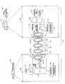
- FIG. 1 is a schematic diagram illustrating an example of an environment in which the power transmission system according to the first embodiment is placed.
- FIG. 2 is a block diagram illustrating a configuration example of the power transmission system.
- FIG. 3 is a schematic diagram showing a first example of attachment of a buoyant body to a coil.
- FIG. 4 is a schematic diagram showing a second example of attaching the buoyancy body to the coil.
- FIG. 5 is a schematic diagram showing a third example of attachment of a buoyant body to a coil.
- FIG. 6 is a schematic diagram showing a fourth example of attachment of a buoyant body to a coil.
- FIG. 7 is a schematic diagram illustrating an example of an environment in which the power transmission system according to the second embodiment is placed.
- FIG. 8 is a schematic diagram illustrating a first modification of an environment where the power transmission system is placed.
- FIG. 9 is a schematic diagram illustrating a second modification of the environment where the power transmission system is placed.
- FIG. 10 is a schematic diagram illustrating a third modification of the environment in which the power transmission system is placed.
- FIG. 11 is a schematic diagram illustrating a fourth modification of the environment where the power transmission system is placed.
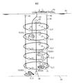
- FIG. 1 is a schematic diagram illustrating an example of an environment in which the power transmission system 10 according to the first embodiment is placed.
- the power transmission system 10 includes a power transmission device 100, a power reception device 200, and a coil CL (see FIG. 2).
- the power transmission device 100 transmits power to the power reception device 200 wirelessly (contactlessly) according to the magnetic resonance method via the plurality of coils CL.
- the number of coils CL to be arranged is n and is arbitrary.
- the coil CL is formed, for example, in an annular shape, and is covered with a resin cover to be insulated.
- the coil CL is, for example, a helical coil or a spiral coil.
- the coil CL is, for example, a cabtyre cable.
- the coil CL includes a power transmission coil CLA and a power reception coil CLB.
- the power transmission coil CLA is a primary coil
- the power reception coil CLB is a secondary coil.
- the coil CL may include one or more relay coils CLC (Booster Coil) disposed between the power transmission coil CLA and the power reception coil CLB.
- the relay coils CLC are arranged substantially in parallel, and more than half of the opening surfaces formed by the relay coils CLC overlap. The interval between the plurality of relay coils CLC is ensured, for example, equal to or greater than the radius of the relay coil CLC.
- the power transmission coil CLA is provided in the power transmission device 100.
- the power receiving coil CLB is provided in the power receiving device 200.
- the relay coil CLC may be provided in the power transmission device 100, the power reception device 200, or provided separately from the power transmission device 100 and the power reception device 200. A part of the relay coil CLC may be provided in the power transmission device 100, and the other part may be provided in the power reception device 200.
- the power transmission coil CLA and the relay coil CLC have a diameter of about 10 m, for example.
- the power receiving coil CLB has a diameter of about 1 m, for example.
- the wire diameter of the coil CL is, for example, about 0.01 m to 0.04 m.
- the number of turns of the coil CL (coil turn) is arbitrary, for example, value 1 or value 5.
- the power transmission device 100 is installed in the ship 50.
- the power receiving device 200 is installed in a movable underwater vehicle 60 (for example, a submersible craft 70 or a submarine excavator 80) or a fixed power receiving device (for example, a seismometer, a monitoring camera, or a geothermal generator).
- Each coil CL is disposed in water (for example, in the sea).
- the submersible 70 may be, for example, a remotely operated unmanned explorer (ROV), an unmanned underwater vehicle (UUV), or a self-sustained unmanned submersible (AUV: Autonomous).
- ROV remotely operated unmanned explorer
- UUV unmanned underwater vehicle
- UUV unmanned underwater vehicle
- AUV self-sustained unmanned submersible
- a part of the ship 50 exists above the water surface 90 (for example, the sea surface), that is, on the water, and the other part of the ship 50 exists below the water surface 90, that is, in the water.
- the ship 50 can move on the water, for example, can move freely on the water of the data acquisition location.
- the power transmission device 100 of the ship 50 and the power transmission coil CLA are connected by the electric wire 20.
- the electric wire 20 is connected to, for example, a driver 151 (see FIG. 2) in the power transmission device 100 via a water connector.
- the underwater vehicle 60 exists underwater or at the bottom 95 (for example, the seabed) and travels underwater or the bottom 95. For example, it is possible to move freely to the data acquisition point according to an instruction from the ship 50 on the water.
- the instruction from the ship 50 may be transmitted by communication via each coil CL, or may be transmitted by other communication methods.
- Each coil CL is connected to the coupling body 30 and is arranged at equal intervals, for example.
- the distance between adjacent coils CL (coil interval) is, for example, 5 m.
- the coil interval is, for example, about half the diameter of the coil CL.
- the power transmission frequency is, for example, 40 kHz or less and preferably less than 10 kHz in consideration of the attenuation amount of the magnetic field strength in water or in the sea.
- the power transmission frequency is, for example, 40 kHz or less and preferably less than 10 kHz in consideration of the attenuation amount of the magnetic field strength in water or in the sea.
- the frequency is less than 10 kHz. Note that the lower the power transmission frequency, the longer the power transmission distance, the larger the coil CL, and the longer the coil interval.
- the inductance of the coil CL is determined based on the transmission frequency, and the diameter and the number of turns of the coil CL are determined.
- the diameter of the coil CL is, for example, several meters to several hundred meters. Further, as the thickness of the coil CL is increased, the electric resistance in the coil CL is reduced and the power loss is reduced.
- the power transmitted through the coil CL is, for example, 50 W or more, and may be on the kW order.
- the transmission frequency is 3 kHz or less.
- the transmission power is 100W.
- the transmission efficiency that is, the ratio of the power transmitted by the power transmission coil CLA and the power received by the power reception coil CLB is 30% or more.
- the power transmission distance by the coil CL is 10 m or more.
- the number of the linked bodies 30 is three, but is not limited thereto.
- a weight 40 is connected to the end of the coupling body 30 on the power receiving coil CLB side.
- a buoy 45 is connected to the end of the coupling body 30 on the power transmission coil CLA side.
- the movement of the connection body 30 can be restricted by the weight 40, and the movement of each coil CL fixed to the connection body 30 can be restricted. Therefore, even if a water flow occurs in the water, the movement of each coil CL is restricted by the weight 40, so that it is possible to suppress a reduction in the efficiency of power transmission using the coil CL.
- the weight 40 is connected to the end on the power receiving coil CLB side, and the buoy 45 is connected to the end on the power transmission coil CLA side, so that the weight 40 becomes the water bottom side and the buoy 45 becomes the water surface side.
- the connection body 30 can maintain a posture that is substantially perpendicular to the water surface. Therefore, the surface defined by each coil CL is substantially parallel to the water surface, and power can be transmitted in the water depth direction (direction substantially orthogonal to the water surface) by the magnetic field resonance method.
- the weight 40 may be detached from the connection body 30 when the connection body 30 is transported, and the weight 40 may be attached to the connection body 30 when the transport of the connection body 30 is completed and installed at a predetermined position. . Thereby, conveyance of the connection body 30 becomes easy.
- the buoyancy body 15 may be connected to the coil CL.
- the coil CL includes a power transmission coil CLA, a power reception coil CLB, and one or more relay coils CLC, and the buoyancy body 15 is connected to the one or more coils CL.
- the coil CL to which the buoyancy body 15 is connected obtains buoyancy by the buoyancy body 15.
- the coil CL preferably obtains neutral buoyancy in water by the buoyancy obtained by the buoyancy body 15.
- the system structure including the plurality of coils CL and the coupling body 30 obtains neutral buoyancy in water as a whole by the buoyancy body 15.
- the system structure includes an underwater facility (for example, a coil CL and a connecting body 30) used for power transmission. Details of the buoyancy body 15 will be described later.
- FIG. 2 is a block diagram illustrating a configuration example of the power transmission system 10.
- the power transmission system 10 includes a power transmission device 100 and a power reception device 200.
- the power transmission apparatus 100 includes a power source 110, an ADC (AC / DC Converter) 120, a CPU (Central Processing Unit) 130, an information communication unit 140, and a power transmission circuit 150.
- ADC AC / DC Converter
- CPU Central Processing Unit
- the ADC 120 converts AC power supplied from the power source 110 into DC power.
- the converted DC power is sent to the power transmission circuit 150.
- the CPU 130 controls the operation of each unit (for example, the power supply 110, the ADC 120, the information communication unit 140, and the power transmission circuit 150) of the power transmission device 100.
- the information communication unit 140 includes a modulation / demodulation circuit 141 for modulating or demodulating communication data communicated with the power receiving apparatus 200.
- the information communication unit 140 transmits control information from the power transmission apparatus 100 to the power reception apparatus 200 via the coil CL.
- the information communication unit 140 receives data from the power receiving device 200 to the power transmitting device 100 via the coil CL.
- This data includes, for example, search result data obtained by underwater exploration or bottom exploration by the power receiving device 200.
- the information communication unit 140 allows the underwater vehicle 60 to quickly perform data communication with the underwater vehicle 60 while performing operations such as data collection.
- the power transmission circuit 150 includes a driver 151 and a resonance circuit 152.
- the driver 151 converts the DC power from the ADC 120 into an AC voltage (pulse waveform) having a predetermined frequency.
- the resonance circuit 152 includes a capacitor CA and a power transmission coil CLA, and generates an AC voltage with a sine wave waveform from an AC voltage with a pulse waveform from the driver 151.
- the power transmission coil CLA resonates at a predetermined resonance frequency according to the AC voltage applied from the driver 151.
- the power transmission coil CLA is impedance matched to the output impedance of the power transmission device 100.
- the power receiving apparatus 200 includes a power receiving circuit 210, a CPU 220, a charge control circuit 230, a secondary battery 240, and an information communication unit 250.
- the power receiving circuit 210 includes a rectifier circuit 211, a regulator 212, and a resonance circuit 213.
- the resonance circuit 213 includes a capacitor CB and a power reception coil CLB, and receives AC power transmitted from the power transmission coil CLA.
- the power receiving coil CLB is impedance matched to the input impedance of the power receiving device 200.
- the rectifier circuit 211 converts AC power induced in the power receiving coil CLB into DC power.
- the regulator 212 converts the DC voltage sent from the rectifier circuit 211 into a predetermined voltage suitable for charging the secondary battery 240.
- the CPU 220 controls the operation of each unit of the power receiving device 200 (for example, the power receiving circuit 210, the charging control circuit 230, the secondary battery 240, and the information communication unit 250).
- the charging control circuit 230 controls charging to the secondary battery 240 according to the type of the secondary battery 240. For example, when the secondary battery 240 is a lithium ion battery, the charging control circuit 230 starts charging the secondary battery 24 with a constant voltage and DC power from the regulator 212.
- the secondary battery 240 stores the electric power transmitted from the power transmission device 100.
- the secondary battery 240 is, for example, a lithium ion battery.
- the information communication unit 250 includes a modulation / demodulation circuit 251 for modulating or demodulating communication data communicated with the power transmission device 100.
- the information communication unit 250 receives control information from the power transmission device 100 to the power reception device 200 via the coil CL.
- the information communication unit 250 transmits data from the power receiving device 200 to the power transmitting device 100 via the coil CL.
- This data includes, for example, search result data obtained by underwater exploration or bottom exploration by the power receiving device 200.
- the information communication unit 250 allows the underwater vehicle 60 to quickly perform data communication with the ship 50 while performing operations such as data collection.
- the relay coil CLC forms a resonance circuit together with the capacitor CC, like the power transmission coil CLA and the power reception coil CLB. That is, in this embodiment, electric power is transmitted by the magnetic resonance method by arranging the resonance circuits in multiple stages in water.
- the resonance circuit 152 when a current flows through the power transmission coil CLA of the power transmission device 100, a magnetic field is generated around the power transmission coil CLA.
- the generated vibration of the magnetic field is transmitted to a resonance circuit including a relay coil CLC that resonates at the same frequency or a resonance circuit 13 including a power receiving coil CLB.
- a current is excited in the relay coil CLC due to the vibration of the magnetic field, a current flows, and a magnetic field is further generated around the relay coil CLC.
- the generated vibration of the magnetic field is transmitted to a resonance circuit including another relay coil CLC that resonates at the same frequency or a resonance circuit 213 including a power receiving coil CLB.
- an alternating current is induced in the power receiving coil CLB by the vibration of the magnetic field of the relay coil CLC or the power transmitting coil CLA.
- the induced alternating current is rectified, converted into a predetermined voltage, and the secondary battery 240 is charged.
- the buoyancy body 15 is connected to at least one coil CL and imparts buoyancy to the coil CL.
- Various materials and structures of the buoyancy body 15 are conceivable.
- the buoyancy body 15 is formed including an air balloon, a polystyrene foam, an epoxy material containing air or not containing air, polyethylene, polypropylene, and the like.
- the buoyancy body 15 may be formed by containing glass beads or microballoons in an epoxy material.
- the buoyancy body 15 may include a bead, and air may be enclosed in the bead.
- the buoyancy body 15 is made of an insulating material.
- the buoyancy body 15 may be formed of a material other than the above having a specific gravity close to that of water (a specific gravity is slightly small).
- Epoxies have superior pressure resistance compared to polyethylene and polypropylene.
- polyethylene and polypropylene are less expensive than epoxy materials.
- the buoyancy can be adjusted by the amount of air contained in the beads or microballoons or by the number of beads or microballoons contained in the buoyancy body 15.
- the surface area of the buoyancy body 15 can be reduced, and the pressure resistance can be improved.
- it is suitable as a buoyancy body 15 connected to a coil CL or a system structure disposed in the deep sea.
- the material and structure of the buoyancy body 15 may be changed according to the water depth where the coil CL to which the buoyancy body 15 is connected is located.
- the buoyancy body 15 is formed including an air balloon, a polystyrene foam, an epoxy material, polyethylene, polypropylene, and the like.
- the buoyancy body 15 includes an epoxy material that does not contain air, an epoxy material containing glass beads or microballoons, air Bead containing, and the like.
- the buoyancy body 15 may be filled with oil.
- Oil has a specific gravity of about 0.8 to 1.0 and is slightly smaller than the specific gravity of water, and is suitable for making the coil CL have neutral buoyancy in water. Note that a liquid other than oil, which is close to the specific gravity of water, may be filled in the buoyancy body 15.
- the buoyancy body 15 by filling the inside of the buoyancy body 15 with a liquid such as oil, the buoyancy body 15 is deformed or damaged by the water pressure around the buoyancy body 15 as compared with the case where the buoyancy body 15 is filled with air. Can be suppressed.
- a liquid such as oil
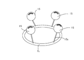
- FIG. 3 is a schematic diagram showing a first attachment example of the buoyancy body 15 to the coil CL.
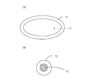
- 4A and 4B are schematic views showing a second example of attachment of the buoyancy body 15 to the coil CL.
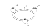
- FIG. 5 is a schematic diagram showing a third example of attachment of the buoyancy body 15 to the coil CL.
- 6A to 6C are schematic views showing a fourth example of attachment of the buoyancy body 15 to the coil CL.
- a balloon method is adopted.
- an air balloon is used as the buoyancy body 15.
- the air balloon is formed to include an epoxy material, polyethylene, polypropylene, or the like as an outer layer of the buoyancy body 15, and the inside of the outer layer is filled with air.
- the buoyancy body 15 is connected to the coil CL via a cable 15a with or without flexibility.
- the buoyancy body 15 may be disposed in water or may be disposed on water.
- the buoyancy body 15 is connected to the annular coil CL at equally spaced positions via a cable 15a.
- the buoyancy applied to the coil CL becomes symmetric (for example, point symmetric) with respect to the center of the coil CL, and the coil CL can be easily made parallel to the water surface 90.
- the number of buoyancy bodies 15 may be 1 to 3, or 5 or more. Further, the surface of the coil CL only needs to follow a desired direction (for example, a direction substantially parallel to the water surface 90), and the buoyancy body 15 may not be connected to the equally spaced positions in the coil CL.
- the coil CL when the coil CL is disposed at a relatively shallow position, neutral buoyancy can be easily given to the coil CL, and transportation and installation of the coil CL can be facilitated. Further, since the work of connecting the buoyancy body 15 with the cable 15a (wire) is sufficient, the installation work is easy.
- FIGS. 4A and 4B a method of covering the entire surface of the coil CL is adopted.
- the outer periphery of the coil CL is surrounded by the buoyancy body 15. That is, the buoyancy body 15 is formed in an annular shape (for example, an annular shape) of the same shape as the coil CL, and is formed in a cylindrical shape (hollow) so as to surround the coil CL. And the buoyancy body 15 encloses the coil CL inside.
- 4A is a schematic view showing the buoyancy body 15 including the coil CL
- FIG. 4B is a cross-sectional view taken along the line A-A ′ of FIG.
- the buoyancy body 15 uniformly covers the periphery of the coil CL, the coil CL obtains buoyancy uniformly at each point on the coil CL. Therefore, the balance of the buoyancy of the coil CL is good, and the coil CL can be prevented from being tilted or rotated from a desired direction. Moreover, the situation where pressure is locally applied with respect to the buoyancy body 15 and the buoyancy body 15 remove
- the mounting method on the inner periphery or outer periphery is adopted.
- the buoyancy body 15 contacts the outer periphery or the inner periphery of the coil CL.
- the contact portion of the outer periphery or inner periphery of the coil CL is bonded with an adhesive, screwed with a screw, or attached with a rope, a binding band, a binding tape, or the like.
- three buoyancy bodies 15 are attached to the outer periphery of the coil CL.
- the number of buoyancy bodies 15 may be 1 to 2, or 4 or more.
- the buoyancy bodies 15 are attached at equal intervals on the coil CL, but the attachment intervals may not be equal.
- the installation work is easy.
- region containing the coil CL and the buoyancy body 15 becomes small, and the influence by water pressure can be reduced.
- the sandwiching method is adopted.
- the buoyancy body 15 encloses a part of the coil CL inside the buoyancy body 15. That is, in the fourth attachment example, a part of the annular buoyancy body 15 shown in the second attachment example is omitted, and a part of the coil CL is exposed.
- FIG. 6A is a schematic diagram showing the coil CL and the buoyancy body 15 that encloses a part of the coil CL.
- FIG. 6B is an enlarged view showing a first example of the area “are” in FIG.
- FIG. 6C is a diagram illustrating a second example of the area “are” in FIG.
- the outer periphery of the coil CL is surrounded by a polyethylene foam 15b (for example, chemically cross-linked polyethylene foam).
- the outer periphery of the polyethylene foam 15b is covered with an outer layer 15c.
- the binding band 15d is attached to the outer layer 15c and bound.
- the buoyancy body 15 has two cut surfaces 15e along the extending direction of the coil CL. That is, the buoyancy body 15 is separated into two. The separated buoyancy body 15 is sandwiched from opposite directions (see reference numeral 15x1) and bound by a binding band 15d (reference numeral 15y1). Thereby, the buoyancy body 15 is attached to the coil CL.
- 6B shows a state in which the buoyancy body 15 is separated along the extending direction of the coil CL on the front side of the buoyancy body 15 in the drawing for the sake of explanation.
- the coil CL and the buoyancy body 15 are disposed in the water with the outer peripheral surface of the coil CL covered with the buoyancy body 15 as on the side.
- 6B illustrates that the buoyancy body 15 is separated into four buoyancy body parts by being separated by a plane orthogonal to the extending direction of the coil CL, but one or more buoyancy body parts are illustrated.
- the buoyancy body portion may be included, and the number of buoyancy body portions included in the buoyancy body 15 is arbitrary.
- the coil CL can obtain buoyancy.
- the buoyancy by a buoyancy body can be easily adjusted by adjusting the number of attachments of the buoyancy body 15.
- the buoyancy body 15 has one cut surface 15e along the extending direction of the coil CL. That is, although the buoyancy body 15 is one, the buoyancy body 15 has a notch and the buoyancy body 15 opens. With the buoyancy body 15 opened, the coil CL is inserted into the buoyancy body 15 (see reference numeral 15x2), and the buoyancy body 15 is closed by matching the cut surface 15e of the buoyancy body 15, and the outer periphery of the buoyancy body 15 is bound. They are bound by a band 15d (see reference numeral 15y2). Thereby, the buoyancy body 15 is attached to the coil CL.
- 6C shows a state in which the buoyancy body 15 is opened along the extending direction of the coil CL on the front side of the buoyancy body 15 in the drawing for the sake of explanation.
- the coil CL and the buoyancy body 15 are disposed in the water with the buoyancy body 15 covering the outer peripheral surface of the coil CL.
- 6C illustrates that the buoyancy body 15 is separated into four buoyancy body parts by being separated by a plane orthogonal to the extending direction of the coil CL.
- the buoyancy body portion may be included, and the number of buoyancy body portions included in the buoyancy body 15 is arbitrary.
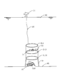
- FIG. 7 is a schematic diagram illustrating an example of an environment in which the power transmission system 400 according to the second embodiment is placed.
- the same reference numerals are used for portions common to the first embodiment.
- the description common to the first embodiment will be omitted as appropriate.
- the power transmission system 400 is different from the first embodiment in that a reflection coil CLR is provided between the power transmission coil CLA and the water surface 90.
- the reflection coil CLR reflects the magnetic field emitted from the power transmission coil CLA toward the water surface 90 toward the water bottom 95. Thereby, it can suppress that the magnetic field discharge
- FIG. Therefore, it is possible to suppress interference between the magnetic field emitted from the power transmission coil CLA and the communication of the ultra long wave (VLF) band or the ultra long wave (ULF) on or in water.
- VLF ultra long wave
- ULF ultra long wave
- the reflection coil CLR is not connected to a capacitor like the power reception coil CLB and the relay coil CLC, and does not form a resonance circuit. That is, the reflection coil CLR is a closed loop without a capacitor.
- the reflection coil CLR is not necessarily a single ring as shown in FIG.
- a second reflection coil having a smaller coil diameter than the reflection coil CLR may be disposed inside the reflection coil CLR so as to be concentric with the reflection coil CLR.
- the buoyancy body 15 may be connected to the coil CL.
- the coil CL includes a power transmission coil CLA, a power reception coil CLB, one or more relay coils CLC, and a reflection coil CLR, and the buoyancy body 15 is connected to the one or more coils CL. Therefore, the buoyancy body 15 may be connected to the reflection coil CLR.
- the coil CL to which the buoyancy body 15 is connected obtains buoyancy by the buoyancy body 15.
- the coil CL preferably obtains neutral buoyancy in water.
- the details of the material / structure and attachment method of the buoyancy body 15 are the same as those in the first embodiment.
- FIG. 8 is a schematic diagram showing a first modification of the environment where the power transmission system 10 is placed.
- a plurality of coils CL (a reflection coil CLR, a power transmission coil CLA, and three relay coils CLC1 to CLC3) are connected via a coupling body 30.
- the UUV 71a travels inside the relay coil CLC2 (in an area surrounded by the relay coil CLC1). Further, the UUV 71b travels below the relay coil CLC3 (in the direction of the water bottom). It has UUV71a, 71b and the receiving coil CLB.
- the power receiving coil CLB is disposed substantially parallel to the water surface 90 so as to receive power transmission using a magnetic field.
- the UUV 71a receives power transmission via the power transmission coil CLA and the relay coil CLC1.
- the UUV 71b receives power transmission via the power transmission coil CLA and the three relay coils CLC1 to CLC3. Thereby, UUV71a, 71b can implement data acquisition activity etc.
- a seismometer 72 and an underwater surveillance camera 73 are installed near the bottom 95 of the relay coil CLC3.
- the seismometer 72 and the underwater monitoring camera 73 have a power receiving coil CLB.
- the power receiving coil CLB is disposed substantially parallel to the water surface 90 so as to receive power transmission using a magnetic field.
- the power receiving coil CLB included in the seismometer 72 and the underwater monitoring camera 73 receives the electric power transmitted from the power transmitting coil CLA through the one or more relay coils CLC as required by the magnetic field resonance method.
- the seismometer 72 receives power from the ship 50 near the water surface 90 without connecting a power supply source and a cable or the like, and without moving close to the power supply source. It becomes possible to detect the seabed shaking as 95.
- the underwater surveillance camera 73 receives power from the ship 50 in the vicinity of the water surface 90, does not connect the power supply source with a cable or the like, and does not move so as to approach the power supply source.
- an image of the vicinity of the sea bottom as the water bottom 95 can be taken, and the vicinity of the sea bottom can be monitored.
- electric power may be transmitted to the non-moving device other than the underwater vehicle 60 using the coil CL.
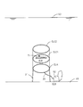
- FIG. 9 is a schematic diagram showing a second modification of the environment where the power transmission system 10 is placed.
- a plurality of coils CL (the power transmission coil CLA and the two relay coils CLC1 and CLC2) are connected via the coupling body 30.
- the solar power generator 51 is arrange
- the solar power generator 51 is connected to the power transmission coil CLA via a submarine cable as the electric wire 20.
- the relay coil CLC ⁇ b> 2 is installed on the water bottom 95 by the support 31. Note that the column 31 may not be in contact with the water bottom 95.
- a self-propelled robot 81 as the bottom excavator 80 travels on the bottom 95.
- the self-propelled robot 81 inspects the underwater or the bottom 95, for example.
- the self-running robot 81 has a power receiving coil CLB.
- the power receiving coil CLB is disposed, for example, substantially in parallel with the water surface 90 so as to receive power from the solar power generator 51 using a magnetic field.
- the power transmission system 10 can supply power from the solar power generator 51 that does not move on the water to the self-propelled robot 81 underwater or on the bottom of the water by the magnetic field resonance method using the coil CL. Therefore, the self-running robot 81 does not need to receive power by wire, and does not need to float near the water surface 90 when receiving power supply. Therefore, the self-running robot 81 can continue the work in the water or in the bottom 95 while receiving power supply.
- a generator other than the solar power generator 51 may be installed on the water.
- connection body 30 is not provided, and the plurality of coils CL (the power transmission coil CLA and the two relay coils CLC1 and CLC2) may not be connected via the connection body 30.
- FIG. 10 is a schematic diagram showing a third modification of the environment where the power transmission system 10 is placed.
- a plurality of coils CL power transmission coil CLA and two relay coils CLC ⁇ b> 1 and CLC ⁇ b> 2 are connected via a coupling body 30.
- the vicinity of the water bottom 95 is a hydrothermal deposit, and a geothermal power generator 52 is installed on the water bottom 95.
- the geothermal power generator 52 is connected to the power transmission coil CLA via an undersea cable as the electric wire 20.
- the power transmission coil CLA is disposed closer to the water bottom 95 than the other coils CL (relay coils CLC1, CLC2).
- the power transmission coil CLA is installed on the water bottom 95 by the support column 31.
- the support column 31 may not be in contact with the water bottom 95.
- the UUV71 sails in the center of relay coil CLC1.
- the UUV 71 has a power receiving coil CLB.
- the power receiving coil CLB is disposed, for example, substantially in parallel with the water surface 90 so as to receive electric power from the geothermal power generator 52 using a magnetic field.
- the power transmission system 10 can supply power from the geothermal power generator 52 that does not move at the bottom 95 to the UUV 71 underwater or at the bottom by magnetic field resonance using the coil CL. Therefore, the UUV 71 does not need to receive power by wire, and does not need to move in the direction of the water bottom 95 when receiving power supply. Therefore, the UUV 71 can continue working in water or in the bottom 95 while receiving power supply.
- FIG. 11 is a schematic diagram showing a fourth modification of the environment where the power transmission system 10 is placed.
- a power transmission coil CLA connected to a power source (for example, a ship 50 or various generators as a power supply source) via a cable is disposed in water.
- a power source for example, a ship 50 or various generators as a power supply source
- the UUV 71 sails and the underwater inspection of the pier 91 is performed.
- the UUV 71 has a power receiving coil CLB.
- the power receiving coil CLB is disposed, for example, substantially in parallel with the water surface 90 so as to receive electric power from the geothermal power generator 52 using a magnetic field.
- the power transmission coil CLA is installed so that the entirety of the plurality of piers 91 existing in the water is included in the power transmission coil CLA, but is not limited thereto.
- the power transmission coil CLA may be disposed so as to include a part of the pier 91 inside the power transmission coil CLA.
- the power transmission system 10 can supply power from the power source to the UUV 71 that is underwater inspection of the pier 91 in water or at the bottom of the water using a magnetic resonance method using the coil CL. Therefore, the UUV 71 does not need to receive power by wire, and does not need to move in the direction of the water bottom 95 when receiving power supply. Therefore, the UUV 71 can continue the underwater inspection of the pier 91 underwater or at the bottom 95 while receiving power supply.
- the power transmission system 10 can be used for marine mineral resource exploration.
- Marine mineral resources include, for example, shale gas, manganese nodules, titanium hydrate, methane hydrate, and rare earths.
- the power transmission system 10 can be used for management and monitoring of fisheries resources.
- the power transmission system 10 can be used for an underwater observation network. Underwater observation includes, for example, earthquake observation, temperature observation, and CO2 observation.
- the power transmission system 10 can be used for maintenance management of the pier 91 and the pier.
- the coil CL and the system structure may sink toward the bottom of the water, and transport in the water may be difficult.
- the coil CL and the system structure can be pulled underwater, the coil CL and the system structure have a large weight, and the force that sinks in the bottom of the water acts greatly.
- the transport ship becomes large in order to transport the coil CL and the system structure, and the installation work of the coil CL and the system structure becomes large.
- the power transmission device 100 transmits power to the power reception device 200 having the power reception coil in water.
- the power transmission device 100 is connected to one or more transmission coils including a power transmission coil CLA that transmits power to the power reception coil CLB via a magnetic field, a driver 151 that transmits AC power to the power transmission coil CLA, and the transmission coil. And a capacitor CA that forms a resonance circuit 152 that resonates with the transmission coil, and a buoyancy body 15 connected to at least one of the transmission coils.
- the driver 151 is an example of a power transmission unit.
- the transmission coil includes a power transmission coil, for example.
- the transmission coil in water is reduced in weight by connecting the buoyancy body 15 to the transmission coil. Therefore, the power transmission systems 10 and 400 can transport the transmission coil and the system structure in water, and can reduce the force that acts when transporting the transmission coil and the system structure.
- the entire system structure may be transported at a time or may be transported in a distributed manner.
- the specific gravity of seawater and the specific gravity of the transmission coil can be made equal. Therefore, the traction force required when transporting the transmission coil or the system structure can be reduced.
- the power transmission systems 10 and 400 can reduce costs such as material costs, transportation costs, and construction costs of the system structure.
- the transport ship can be downsized. Further, since the transmission coil and the system structure have neutral buoyancy, the transmission coil and the system structure can be transported from the sea, and can be transported by towing by a transport ship. In addition, the inertial force at the time of transporting the transmission coil and the system structure is reduced, and the shaking of the transport ship can be reduced. Moreover, since the weight of the transmission coil and the system structure is reduced, disconnection of the cable connecting the system structure and the transport ship can be suppressed.
- the power transmission device 100 and the power transmission systems 10 and 400 can reduce various costs related to the installation of the transmission coil for transmitting power in water.
- the power transmission device 100 may include the coupling body 30.
- the transmission coil may include at least one relay coil CLC that transmits power to the power reception coil CLB using a magnetic field from the power transmission coil CLA.
- the connection body 30 may connect the power transmission coil CLA and the relay coil CLC.
- the power transmission apparatus 100 can make the relay coil CLC neutral buoyancy by connecting the buoyancy body 15 to the relay coil CLC, and can easily arrange the relay coil CLC at a desired position. Power transmission between 100 and the power receiving apparatus 200 can be suitably relayed.
- the power transmission device 100 can extend the power transmission distance using the relay coil CLC. Further, similarly to the above, various costs related to the installation of the relay coil CLC can be reduced.
- the power transmission apparatus 100 can restrict
- the transmission coil may include a reflection coil CLR that reflects the magnetic field generated by the power transmission coil CLA toward the water bottom 95.
- the power transmission apparatus 100 can make the reflection coil CLR neutral buoyancy by connecting the buoyancy body 15 to the transmission coil, and can easily arrange the reflection coil CLR at a desired position.
- the power transmission device 100 can suppress the magnetic field emitted from the power transmission coil CLA from being released from the water surface 90, and communication between the magnetic field emitted from the power transmission coil CLA and the ultra-long wave band or the ultra-long wave on the water or in water. Interference can be suppressed. Therefore, the power transmission device 100 can improve the power transmission efficiency with the power receiving device 200.
- the buoyancy body 15 may be connected to the coupling body 30.
- the connection body 30 can be made into neutral buoyancy, and conveyance of the system structure containing the connection body 30 can be facilitated. Therefore, similarly to the above, various costs related to the installation of the system structure can be reduced.
- buoyancy bodies 15 may be connected at equally spaced positions in the transmission coil.
- the power transmission device 100 can uniformly apply buoyancy to the transmission coil at a point-symmetrical position with respect to the central portion of the transmission coil. Therefore, after the transmission coil is installed in water, for example, it becomes easy to maintain the posture of the transmission coil along a plane parallel to the water surface 90, and the loss of the magnetic field passing through the transmission coil can be reduced.
- the buoyancy body 15 may be connected to the transmission coil via the cable 15a and filled with air.
- the buoyancy body 15 can be easily handled by fixing the buoyancy body 15 to the transmission coil with a wire as the cable 15a. Further, since the air balloon is used, the buoyancy body 15 can be configured at low cost. Moreover, the buoyancy by the buoyancy body 15 can be easily adjusted by adjusting the number of attachments of the buoyancy body 15.
- buoyancy body 15 may contact the inner periphery or the outer periphery of the transmission coil.
- the buoyancy body 15 can be directly attached to the transmission coil, and the attachment work of the buoyancy body 15 can be facilitated. Moreover, when the buoyancy body 15 contacts the inner periphery of the transmission coil, the area of the region including the transmission coil and the buoyancy body 15 can be reduced, and the influence of power flow and the like can be reduced.
- the buoyancy body 15 may be formed in a cylindrical shape and an annular shape, and the transmission coil may be included in the buoyancy body 15.
- the power transmission device 100 can reduce the surface area in which the transmission coil and the buoyancy body 15 receive a force such as a tidal current because the buoyancy body 15 includes the transmission coil. Therefore, the durability of the buoyancy body 15 is improved. Further, the transmission coil can be protected by covering the entire outer periphery of the transmission coil. Moreover, since the buoyancy body 15 includes the transmission coil and is integrally formed, the buoyancy body 15 does not become a protrusion, and the buoyancy body 15 can receive water pressure uniformly.
- the buoyancy body 15 may include a part of the transmission coil therein. Thereby, a buoyancy can be given to a transmission coil partially, for example, can be made neutral buoyancy. In addition, as compared with the case where the entire transmission coil is included in the buoyancy body 15, the material of the buoyancy body 15 can be reduced and the transmission coil can be configured at low cost.
- the buoyancy body 15 may be filled with oil.
- the power transmission device 100 can suppress the buoyancy body 15 from being deformed or damaged by water pressure by filling the buoyancy body 15 with oil.
- the buoyancy body may be formed of different materials depending on the water depth where the transmission coil is disposed.
- the transmission coil may transmit power in a direction substantially orthogonal to the water surface 90.
- the power transmission device 100 can extend the power transmission distance in the water depth direction, can supply power to the power reception device 200 located in a deep water location (deep sea), and can improve the work efficiency of the power reception device 200.
- the transmission coil may transmit power and communicate data.
- the power receiving apparatus 200 can charge the power from the power transmission apparatus 100 while suppressing a decrease in activity efficiency such as data collection, and can perform data communication with the power transmission apparatus 100.
- the power reception device 200 (for example, the underwater vehicle 60) does not need to contact the power transmission coil CLA even in an environment where there is an underwater flow, and the magnetic resonance method. Therefore, it is possible to stably receive power supply by suppressing the reduction in efficiency of power transmission. Therefore, the underwater vehicle 60 can receive continuous power supply while performing activities such as data collection, and the operating rate of the underwater vehicle 60 when receiving power supply is improved. Therefore, the power transmission device 100 can improve the efficiency of data collection activities in water.
- the power transmission device 100 can transmit power wirelessly by the magnetic resonance method by using the power transmission coil CLA of the power transmission device 100 and the power reception coil CLB of the power reception device 200. Moreover, since the underwater vehicle 60 can receive power without moving the underwater vehicle 60 to a predetermined power supply location, the underwater vehicle 60 can move freely even during power supply, and position-free power transmission is possible. It becomes. Therefore, the power transmission device 100 can suppress the activity of the underwater vehicle 60 underwater or at the bottom 95 from being inhibited. Therefore, the underwater vehicle 60 can expand the work range even during charging, and can be continuously charged during work. Moreover, since the underwater vehicle 60 can be charged at an arbitrary timing, the working time can be shortened.
- the power transmission device 100 can extend the power transmission distance by continuous electromagnetic induction by using the relay coil CLC. For example, as illustrated in FIG. 1, by arranging the relay coils CLC in multiple stages from the vicinity of the water surface 90 toward the bottom of the water, the power transmission device 100 can transmit power to a deep water position (for example, a water depth of 1000 m or more). In this case, the power transmission device 100 can wirelessly transmit power to the underwater vehicle 60 that performs mining and investigation of the seabed resources, and can suppress a decrease in the operating rate of the underwater vehicle 60 during power feeding.
- a deep water position for example, a water depth of 1000 m or more.
- the power transmission device 100 can wirelessly transmit power to the underwater vehicle 60 that performs mining and investigation of the seabed resources, and can suppress a decrease in the operating rate of the underwater vehicle 60 during power feeding.
- the underwater vehicle 60 can be active. In this case, the underwater vehicle 60 can be reduced in size and weight.
- the first and second embodiments have been described as examples of the technology in the present disclosure.
- the technology in the present disclosure is not limited to this, and can also be applied to embodiments in which changes, replacements, additions, omissions, and the like are performed.
- the buoyant body 15 is illustrated as being filled with a liquid such as oil, but the coil CL may be filled with a liquid such as oil.
- a coil is comprised including the electric wire wound once or more, and the coating
- the coil CL When the liquid such as oil is enclosed in the coil CL, the coil CL is hardly deformed and is not easily damaged. Even when the buoyancy body 15 is not used, a certain degree of buoyancy is applied to the coil CL, and the coil CL can be easily transported.
- the circumference of the electric wire formed in an annular shape may be covered with the covering material, and oil may be filled between the electric wire and the covering material.
- buoyancy is imparted to the transmission coil itself by the oil in the transmission coil. Therefore, when trying to obtain neutral buoyancy by the sum of the buoyancy of the transmission coil itself and the buoyancy of the buoyancy body 15 connected to the transmission coil, the buoyancy by the buoyancy body 15 can be reduced, and the cost of the buoyancy body 15 can be reduced.
- the buoyancy body 15 is connected to the transmission coil (for example, the power transmission coil CLA, the relay coil CLC, or the reflection coil CLR), but the buoyancy body 15 is connected to the power reception coil CLB. May be.
- the power transmission system 10 can reduce the weight load of the underwater vehicle 60 (for example, AUV) equipped with the power receiving coil CLB, and can reduce the power consumption of the underwater vehicle 60 (for example, the power consumption of the secondary battery 240). Can be suppressed.
- the buoyancy body 15 is connected to the coil CL.
- various cables for example, the electric wire 20 and the cable 15a used in water.
- the attachment method of the buoyancy body 15 to various cables is the same as the attachment method of the buoyancy body 15 to the coil CL, for example. Thereby, for example, like the coil CL, various cables can be easily transported in water.
- the buoyancy body 15 is connected to the coil CL.
- the buoyancy body 15 may be connected to the coupling body 30 (for example, a rope), and the buoyancy body is connected to the support 31. 15 may be connected.
- pillar 31 is the same as the attachment method of the buoyancy body 15 to the coil CL, for example.
- pillar 31 can be easily conveyed in the water.
- the buoyancy body 15 connected to the coupling body 30 may be a buoy 45 or a buoyancy body provided separately from the buoy 45.
- the buoyant body 15 is illustrated as having a spherical shape in FIGS. 3 and 5, but other shapes may be used.
- 4A and 4B and FIGS. 6A to 6C are cross-sectional views cut along a plane orthogonal to the extending direction of the coil CL, the outer peripheral shape of the buoyant body is circular. Although exemplified, there may be other shapes.
- the underwater vehicle 60 includes the secondary battery 240 so that underwater charging is possible.
- the underwater vehicle 60 may not include the secondary battery 240. Even in this case, the underwater vehicle 60 can be supplied with electric power through each coil CL, that is, can be supplied with water underwater.
- the power transmission system 10 is exemplified by a submarine camera system that performs data collection or the like in the sea or the sea floor, but may be applied to other uses.
- the power receiving device 200 may be provided in an underwater robot or an unmanned explorer equipped with various sensors, and may be disposed in the water or in the bottom 95. This makes it possible to manage marine resources and aquaculture, maintain and manage infrastructure systems such as bridges and dams, and monitor the seabed of harbors, etc., using underwater robots and unmanned explorers.
- the power transmission coil CLA, the relay coil CLC, and the power reception coil CLB are arranged side by side from the water surface 90 toward the water bottom 95, but the arrangement direction of the coil CL is this. Not limited to.
- the power transmission coil CLA, the relay coil CLC, and the power reception coil CLB may be arranged side by side in the direction along the water surface 90 or the water bottom 95. Thereby, the power transmission apparatus 100 can transmit electric power horizontally in water.
- the CPUs 130 and 220 are exemplified, but a processor other than the CPUs 130 and 220 may be used.
- the processor may be physically configured in any manner. Further, if a programmable processor is used, the processing contents can be changed by changing the program, so that the degree of freedom in designing the processor can be increased.
- the processor may be composed of one semiconductor chip or physically composed of a plurality of semiconductor chips. When configured by a plurality of semiconductor chips, each control of the first embodiment may be realized by separate semiconductor chips. In this case, it can be considered that a plurality of semiconductor chips constitute one processor.
- the processor may be configured by a member (capacitor or the like) having a function different from that of the semiconductor chip. Further, one semiconductor chip may be configured so as to realize the functions of the processor and other functions.
- the present disclosure is useful for a power transmission device that can reduce various costs related to installation of a coil for transmitting power in water.
Abstract
Provided is an electric power transmission device capable of effectively wirelessly transmitting power to an underwater vehicle in water. The electric power transmission device transmits power to an electric power receiving device having a power receiving coil in water and is provided with: one or more transmission coils including a power transmission coil for transmitting power to the power receiving coil through a magnetic field; an electric power transmission unit transmitting AC power to the power transmission coil; capacitors connected to the transmission coils and forming resonant circuits that are resonant together with the transmission coils; and a buoyant body connected to at least one of the transmission coils.
Description
本開示は、水中において無線で送電する送電装置に関する。
The present disclosure relates to a power transmission device that wirelessly transmits power in water.
送電装置としての水中基地局が、受電装置としての水中航走体との間で、磁気共鳴方式を用いて非接触で電力伝送することが知られている(例えば特許文献1参照)。この送電装置は、送電用共鳴コイルと、風船と、風船制御機構と、を具備する。送電用共鳴コイルは、磁界共鳴方式により受電装置の受電用共鳴コイルに非接触で電力伝送する。風船は、送電用共鳴コイルを内包する。風船制御機構は、風船を電力伝送時に膨張させることにより、送電用共鳴コイルと受電用共鳴コイルとの間の水を排除する。
It is known that an underwater base station as a power transmission device transmits power in a contactless manner with an underwater vehicle as a power receiving device using a magnetic resonance method (see, for example, Patent Document 1). The power transmission device includes a power transmission resonance coil, a balloon, and a balloon control mechanism. The power transmission resonance coil transmits power in a non-contact manner to the power reception resonance coil of the power receiving device by a magnetic field resonance method. The balloon contains a power transmission resonance coil. The balloon control mechanism removes water between the power transmission resonance coil and the power reception resonance coil by expanding the balloon during power transmission.
また、13.56MHz帯の周波数を用いる電磁誘導方式を利用して、電力とデータをIC搭載媒体に送信するアンテナ装置が知られている(例えば特許文献2参照)。このアンテナ装置は、信号電流が給電される少なくとも1つの給電ループアンテナと信号電流が給電されない少なくとも1つの無給電ループアンテナを有し、給電ループアンテナが発生する磁界を利用して無給電ループアンテナにも信号電流を発生させ、給電ループアンテナの通信範囲を拡大させる点を開示している。
In addition, an antenna device that transmits power and data to an IC-mounted medium using an electromagnetic induction method using a frequency of 13.56 MHz band is known (see, for example, Patent Document 2). This antenna apparatus has at least one feeding loop antenna to which a signal current is fed and at least one parasitic loop antenna to which no signal current is fed, and uses the magnetic field generated by the feeding loop antenna as a parasitic loop antenna. Also discloses that a signal current is generated and the communication range of the feed loop antenna is expanded.
ところで、送電装置と受電装置とが水中で接近せずに磁気共鳴方式により電力伝送するためには、少なくとも1つのコイルを水中の所定位置に設置する必要がある。この場合において、磁気共鳴方式の電力伝送に用いる周波数が比較的低い場合、コイルの直径を長くする必要がある。コイルの直径が大きいと、コイルが重くなり、コイルが水底方向に沈みやすくなる。
By the way, in order to transmit power by the magnetic resonance method without the power transmission device and the power reception device approaching in water, it is necessary to install at least one coil at a predetermined position in water. In this case, when the frequency used for magnetic resonance power transmission is relatively low, it is necessary to increase the coil diameter. If the diameter of the coil is large, the coil becomes heavier and the coil tends to sink in the bottom direction.
また、水中にコイルを設置するためには、コイルを所望の位置に固定するための支柱やロープが必要となるが、コイルの比重が水や海水の比重よりも大きい場合、支柱やロープの耐力を大きくする必要がある。そのため、コイル設置のための建設費やコイルの材料費が高くなる。また、コイルが重いと、コイルを運搬する船の大型化が必要となり、コイルを運搬するための輸送コストも高くなる。
In addition, in order to install the coil in the water, it is necessary to have a support and rope to fix the coil in the desired position. If the specific gravity of the coil is greater than that of water and seawater, the strength of the support and rope Need to be larger. Therefore, the construction cost for coil installation and the material cost of the coil become high. Further, if the coil is heavy, it is necessary to increase the size of the ship that carries the coil, and the transportation cost for carrying the coil also increases.
本開示は、水中において電力伝送するためのコイルの設置に係る様々なコストを低減することを目的とする。
This disclosure aims to reduce various costs related to the installation of a coil for transmitting power in water.
本開示の送電装置は、水中において、受電コイルを有する受電装置に電力を伝送する。送電装置は、磁界を介して受電コイルに電力を伝送する送電コイルを含む1つ以上の伝送コイルと、交流電力を送電コイルへ送電する送電部と、伝送コイルに接続されると共に、伝送コイルと共に共振する共振回路を形成するコンデンサと、伝送コイルの少なくとも1つに接続された浮力体と、を備える。
The power transmission device of the present disclosure transmits power to a power reception device having a power reception coil in water. The power transmission device includes one or more transmission coils including a power transmission coil that transmits power to the power reception coil via a magnetic field, a power transmission unit that transmits AC power to the power transmission coil, and the transmission coil. A capacitor that forms a resonant circuit that resonates; and a buoyant body connected to at least one of the transmission coils.
本開示によれば、水中において電力伝送するためのコイルの設置に係る様々なコストを低減できる。
According to the present disclosure, it is possible to reduce various costs related to installation of a coil for transmitting power in water.
以下、適宜図面を参照しながら、実施形態を詳細に説明する。但し、必要以上に詳細な説明は省略する場合がある。例えば、既によく知られた事項の詳細説明や実質的に同一の構成に対する重複説明を省略する場合がある。これは、以下の説明が不必要に冗長になることを避け、当業者の理解を容易にするためである。尚、添付図面及び以下の説明は、当業者が本開示を十分に理解するために提供されるものであり、これらにより特許請求の範囲に記載の主題を限定することは意図されていない。
Hereinafter, embodiments will be described in detail with reference to the drawings as appropriate. However, more detailed description than necessary may be omitted. For example, detailed descriptions of already well-known matters and repeated descriptions for substantially the same configuration may be omitted. This is to avoid the following description from becoming unnecessarily redundant and to facilitate understanding by those skilled in the art. The accompanying drawings and the following description are provided to enable those skilled in the art to fully understand the present disclosure, and are not intended to limit the claimed subject matter.
(第1の実施形態)
図1は、第1の実施形態における電力伝送システム10が置かれる環境の一例を示す模式図である。電力伝送システム10は、送電装置100、受電装置200、及びコイルCLを備える(図2参照)。送電装置100は、受電装置200に対して、複数のコイルCLを介して、磁気共鳴方式に従ってワイヤレス(無接点)で電力伝送する。配置されるコイルCLの数は、n個であり、任意である。 (First embodiment)
FIG. 1 is a schematic diagram illustrating an example of an environment in which thepower transmission system 10 according to the first embodiment is placed. The power transmission system 10 includes a power transmission device 100, a power reception device 200, and a coil CL (see FIG. 2). The power transmission device 100 transmits power to the power reception device 200 wirelessly (contactlessly) according to the magnetic resonance method via the plurality of coils CL. The number of coils CL to be arranged is n and is arbitrary.
図1は、第1の実施形態における電力伝送システム10が置かれる環境の一例を示す模式図である。電力伝送システム10は、送電装置100、受電装置200、及びコイルCLを備える(図2参照)。送電装置100は、受電装置200に対して、複数のコイルCLを介して、磁気共鳴方式に従ってワイヤレス(無接点)で電力伝送する。配置されるコイルCLの数は、n個であり、任意である。 (First embodiment)
FIG. 1 is a schematic diagram illustrating an example of an environment in which the
コイルCLは、例えば、環状に形成され、樹脂のカバーで被覆されて絶縁されている。コイルCLは、例えば、ヘリカルコイルやスパイラルコイルである。また、コイルCLは、例えばキャプタイヤケーブルである。コイルCLは、送電コイルCLA及び受電コイルCLBを含む。送電コイルCLAは、一次コイル(Primary Coil)であり、受電コイルCLBは、二次コイル(Secondary Coil)である。
The coil CL is formed, for example, in an annular shape, and is covered with a resin cover to be insulated. The coil CL is, for example, a helical coil or a spiral coil. The coil CL is, for example, a cabtyre cable. The coil CL includes a power transmission coil CLA and a power reception coil CLB. The power transmission coil CLA is a primary coil, and the power reception coil CLB is a secondary coil.
また、コイルCLは、送電コイルCLAと受電コイルCLBとの間に配置された1つ以上の中継コイルCLC(Booster Coil)を含んでもよい。中継コイルCLC同志は、略平行に配置され、中継コイルCLCにより形成される開口面の半分以上が重なる。複数の中継コイルCLC間の間隔は、例えば中継コイルCLCの半径以上確保される。
The coil CL may include one or more relay coils CLC (Booster Coil) disposed between the power transmission coil CLA and the power reception coil CLB. The relay coils CLC are arranged substantially in parallel, and more than half of the opening surfaces formed by the relay coils CLC overlap. The interval between the plurality of relay coils CLC is ensured, for example, equal to or greater than the radius of the relay coil CLC.
送電コイルCLAは、送電装置100に設けられる。受電コイルCLBは、受電装置200に設けられる。中継コイルCLCは、送電装置100に設けられても、受電装置200に設けられても、送電装置100及び受電装置200とは別に設けられてもよい。中継コイルCLCは、一部が送電装置100に設けられ、他の一部が受電装置200に設けられてもよい。
The power transmission coil CLA is provided in the power transmission device 100. The power receiving coil CLB is provided in the power receiving device 200. The relay coil CLC may be provided in the power transmission device 100, the power reception device 200, or provided separately from the power transmission device 100 and the power reception device 200. A part of the relay coil CLC may be provided in the power transmission device 100, and the other part may be provided in the power reception device 200.
また、送電コイルCLA及び中継コイルCLCは、例えば直径が10m程度である。受電コイルCLBは、例えば直径が1m程度である。コイルCLの線径は、例えば0.01m~0.04m程度である。コイルCLの巻き数(コイルターン)は、任意であり、例えば値1や値5である。
Further, the power transmission coil CLA and the relay coil CLC have a diameter of about 10 m, for example. The power receiving coil CLB has a diameter of about 1 m, for example. The wire diameter of the coil CL is, for example, about 0.01 m to 0.04 m. The number of turns of the coil CL (coil turn) is arbitrary, for example, value 1 or value 5.
送電装置100は、船舶50に設置される。受電装置200は、移動可能な水中航走体60(例えば潜水艇70や水底掘削機80)や固定的に設置される受電装置(例えば地震計、監視カメラ、地熱発電機)に設置される。各コイルCLは、水中(例えば海中)に配置される。
The power transmission device 100 is installed in the ship 50. The power receiving device 200 is installed in a movable underwater vehicle 60 (for example, a submersible craft 70 or a submarine excavator 80) or a fixed power receiving device (for example, a seismometer, a monitoring camera, or a geothermal generator). Each coil CL is disposed in water (for example, in the sea).
潜水艇70は、例えば、遠隔操作無人探査機(ROV:Remotely Operated Vehicle)、無人潜水艇(UUV:Unmanned Underwater Vehicle)、又は自立型無人潜水機(AUV:Autonomous Underwater Vehicle)を含んでもよい。
The submersible 70 may be, for example, a remotely operated unmanned explorer (ROV), an unmanned underwater vehicle (UUV), or a self-sustained unmanned submersible (AUV: Autonomous).
船舶50の一部は、水面90(例えば海面)より上部つまり水上に存在し、船舶50の他の一部は、水面90よりも下部つまり水中に存在する。船舶50は、水上で移動可能であり、例えばデータ取得場所の水上へ自由に移動可能である。船舶50の送電装置100と送電コイルCLAとの間は、電線20により接続される。電線20は、水上のコネクタを介して、例えば送電装置100内のドライバ151(図2参照)と接続される。
A part of the ship 50 exists above the water surface 90 (for example, the sea surface), that is, on the water, and the other part of the ship 50 exists below the water surface 90, that is, in the water. The ship 50 can move on the water, for example, can move freely on the water of the data acquisition location. The power transmission device 100 of the ship 50 and the power transmission coil CLA are connected by the electric wire 20. The electric wire 20 is connected to, for example, a driver 151 (see FIG. 2) in the power transmission device 100 via a water connector.
水中航走体60は、水中又は水底95(例えば海底)に存在し、水中又は水底95を航走する。例えば、水上の船舶50からの指示により、データ取得ポイントへ自由に移動可能である。船舶50からの指示は、各コイルCLを介した通信により伝送されてもよいし、その他の通信方法により伝送されてもよい。
The underwater vehicle 60 exists underwater or at the bottom 95 (for example, the seabed) and travels underwater or the bottom 95. For example, it is possible to move freely to the data acquisition point according to an instruction from the ship 50 on the water. The instruction from the ship 50 may be transmitted by communication via each coil CL, or may be transmitted by other communication methods.
各コイルCLは、連結体30と接続され、例えば等間隔に配置される。隣り合うコイルCL間の距離(コイル間隔)は、例えば5mである。コイル間隔は、例えばコイルCLの直径の半分程度の長さである。送電周波数は、水中又は海中での磁界強度の減衰量を考慮すると、例えば40kHz以下であり、10kHz未満とされることが好ましい。また、10kHz以上の送信周波数で電力伝送する場合には、電波法の規定に基づいて所定のシミュレーションを行う必要があり、10kHz未満の場合にはこの作業を省略できる。尚、送電周波数が低周波であるほど、電力伝送距離が長くなり、コイルCLが大きくなり、コイル間隔を長くなる。
Each coil CL is connected to the coupling body 30 and is arranged at equal intervals, for example. The distance between adjacent coils CL (coil interval) is, for example, 5 m. The coil interval is, for example, about half the diameter of the coil CL. The power transmission frequency is, for example, 40 kHz or less and preferably less than 10 kHz in consideration of the attenuation amount of the magnetic field strength in water or in the sea. In addition, when power is transmitted at a transmission frequency of 10 kHz or more, it is necessary to perform a predetermined simulation based on the regulations of the Radio Law, and this work can be omitted when the frequency is less than 10 kHz. Note that the lower the power transmission frequency, the longer the power transmission distance, the larger the coil CL, and the longer the coil interval.
また、送電周波数に基づいてコイルCLのインダクタンスが定まり、コイルCLの直径と巻き数とが定まる。コイルCLの直径は、例えば数m~数100mである。また、コイルCLの太さが太い程、コイルCLでの電気抵抗が減り、電力損失が小さくなる。また、コイルCLを介して伝送される電力は、例えば50W以上であり、kWオーダーでもよい。
Further, the inductance of the coil CL is determined based on the transmission frequency, and the diameter and the number of turns of the coil CL are determined. The diameter of the coil CL is, for example, several meters to several hundred meters. Further, as the thickness of the coil CL is increased, the electric resistance in the coil CL is reduced and the power loss is reduced. The power transmitted through the coil CL is, for example, 50 W or more, and may be on the kW order.
本実施形態では、一例として、送信周波数は3kHz以下である。送信電力は、100Wである。送信効率、つまり送電コイルCLAによる送電電力と受電コイルCLBによる受電電力との比率は、30%以上である。コイルCLによる送電距離は、10m以上である。
In this embodiment, as an example, the transmission frequency is 3 kHz or less. The transmission power is 100W. The transmission efficiency, that is, the ratio of the power transmitted by the power transmission coil CLA and the power received by the power reception coil CLB is 30% or more. The power transmission distance by the coil CL is 10 m or more.
図1では、連結体30の数が3つであるが、これに限られない。連結体30における受電コイルCLB側の端部には、錘40が接続される。連結体30における送電コイルCLA側の端部には、ブイ(Buoy)45が接続される。
In FIG. 1, the number of the linked bodies 30 is three, but is not limited thereto. A weight 40 is connected to the end of the coupling body 30 on the power receiving coil CLB side. A buoy 45 is connected to the end of the coupling body 30 on the power transmission coil CLA side.
錘40により、連結体30の移動を規制でき、連結体30に固定された各コイルCLの移動を規制できる。よって、水中において水流が発生しても、錘40により各コイルCLの移動が規制されるので、コイルCLを用いた電力伝送の効率が低下することを抑制できる。
The movement of the connection body 30 can be restricted by the weight 40, and the movement of each coil CL fixed to the connection body 30 can be restricted. Therefore, even if a water flow occurs in the water, the movement of each coil CL is restricted by the weight 40, so that it is possible to suppress a reduction in the efficiency of power transmission using the coil CL.
また、連結体30において、受電コイルCLB側の端部に錘40が接続され、送電コイルCLA側の端部にブイ45が接続されることで、錘40が水底側、ブイ45が水面側となり、連結体30が水面と略垂直となる姿勢を維持できる。よって、各コイルCLにより定義される面は、水面と略平行となり、磁界共鳴方式によって水深方向(水面と略直交する方向)に電力伝送できる。
Further, in the coupling body 30, the weight 40 is connected to the end on the power receiving coil CLB side, and the buoy 45 is connected to the end on the power transmission coil CLA side, so that the weight 40 becomes the water bottom side and the buoy 45 becomes the water surface side. The connection body 30 can maintain a posture that is substantially perpendicular to the water surface. Therefore, the surface defined by each coil CL is substantially parallel to the water surface, and power can be transmitted in the water depth direction (direction substantially orthogonal to the water surface) by the magnetic field resonance method.
尚、錘40は、連結体30の運搬時には連結体30から取り外され、連結体30の運搬が終了し、所定の位置に設置される際に、連結体30に錘40が取り付けられてもよい。これにより、連結体30の運搬が容易になる。
The weight 40 may be detached from the connection body 30 when the connection body 30 is transported, and the weight 40 may be attached to the connection body 30 when the transport of the connection body 30 is completed and installed at a predetermined position. . Thereby, conveyance of the connection body 30 becomes easy.
また、コイルCLには、浮力体15が接続されてもよい。コイルCLには、送電コイルCLA、受電コイルCLB、及び1つ以上の中継コイルCLCが含まれるが、1つ以上のコイルCLに浮力体15が接続される。浮力体15により、浮力体15が接続されたコイルCLが浮力を得る。コイルCLは、浮力体15により得た浮力により、水中において中性浮力を得ることが好ましい。
Further, the buoyancy body 15 may be connected to the coil CL. The coil CL includes a power transmission coil CLA, a power reception coil CLB, and one or more relay coils CLC, and the buoyancy body 15 is connected to the one or more coils CL. The coil CL to which the buoyancy body 15 is connected obtains buoyancy by the buoyancy body 15. The coil CL preferably obtains neutral buoyancy in water by the buoyancy obtained by the buoyancy body 15.
また、浮力体15により、複数のコイルCL及び連結体30を含むシステム構造物は、全体として水中において中性浮力を得ることが好ましい。中性浮力を得ることにより、例えばシステム構造物の水中での運搬が容易になる。システム構造物は、電力伝送に用いられる水中の設備(例えばコイルCL、連結体30)を含む。浮力体15の詳細については後述する。
Further, it is preferable that the system structure including the plurality of coils CL and the coupling body 30 obtains neutral buoyancy in water as a whole by the buoyancy body 15. By obtaining neutral buoyancy, for example, the system structure can be easily transported in water. The system structure includes an underwater facility (for example, a coil CL and a connecting body 30) used for power transmission. Details of the buoyancy body 15 will be described later.
図2は、電力伝送システム10の構成例を示すブロック図である。電力伝送システム10は、送電装置100及び受電装置200を備える。
FIG. 2 is a block diagram illustrating a configuration example of the power transmission system 10. The power transmission system 10 includes a power transmission device 100 and a power reception device 200.
送電装置100は、電源110、ADC(AC/DC Converter)120、CPU(Central Processing Unit)130、情報通信部140、及び送電回路150、を備える。
The power transmission apparatus 100 includes a power source 110, an ADC (AC / DC Converter) 120, a CPU (Central Processing Unit) 130, an information communication unit 140, and a power transmission circuit 150.
ADC120は、電源110から供給される交流電力を直流電力に変換する。変換された直流電力は、送電回路150へ送られる。
The ADC 120 converts AC power supplied from the power source 110 into DC power. The converted DC power is sent to the power transmission circuit 150.
CPU130は、送電装置100の各部(例えば電源110、ADC120、情報通信部140、送電回路150)の動作を統括する。
The CPU 130 controls the operation of each unit (for example, the power supply 110, the ADC 120, the information communication unit 140, and the power transmission circuit 150) of the power transmission device 100.
情報通信部140は、受電装置200との間で通信される通信データを変調又は復調するための変復調回路141を含む。情報通信部140は、例えば、送電装置100から受電装置200への制御情報を、コイルCLを介して送信する。情報通信部140は、例えば、受電装置200から送電装置100へのデータを、コイルCLを介して受信する。このデータは、例えば、受電装置200により水中探査や水底探査された探査結果のデータが含まれる。情報通信部140により、水中航走体60がデータ収集等の作業しながら、水中航走体60との間で迅速にデータ通信できる。
The information communication unit 140 includes a modulation / demodulation circuit 141 for modulating or demodulating communication data communicated with the power receiving apparatus 200. For example, the information communication unit 140 transmits control information from the power transmission apparatus 100 to the power reception apparatus 200 via the coil CL. For example, the information communication unit 140 receives data from the power receiving device 200 to the power transmitting device 100 via the coil CL. This data includes, for example, search result data obtained by underwater exploration or bottom exploration by the power receiving device 200. The information communication unit 140 allows the underwater vehicle 60 to quickly perform data communication with the underwater vehicle 60 while performing operations such as data collection.
送電回路150は、ドライバ151及び共振回路152を含む。ドライバ151は、ADC120からの直流電力を所定の周波数の交流電圧(パルス波形)に変換する。共振回路152は、コンデンサCAと送電コイルCLAとを含んで構成され、ドライバ151からのパルス波形の交流電圧から正弦波波形の交流電圧を生成する。送電コイルCLAは、ドライバ151から印加される交流電圧に応じて、所定の共振周波数で共振する。尚、送電コイルCLAは、送電装置100の出力インピーダンスにインピーダンス整合される。
The power transmission circuit 150 includes a driver 151 and a resonance circuit 152. The driver 151 converts the DC power from the ADC 120 into an AC voltage (pulse waveform) having a predetermined frequency. The resonance circuit 152 includes a capacitor CA and a power transmission coil CLA, and generates an AC voltage with a sine wave waveform from an AC voltage with a pulse waveform from the driver 151. The power transmission coil CLA resonates at a predetermined resonance frequency according to the AC voltage applied from the driver 151. The power transmission coil CLA is impedance matched to the output impedance of the power transmission device 100.
受電装置200は、受電回路210、CPU220、充電制御回路230、2次電池240、及び情報通信部250を備える。
The power receiving apparatus 200 includes a power receiving circuit 210, a CPU 220, a charge control circuit 230, a secondary battery 240, and an information communication unit 250.
受電回路210は、整流回路211、レギュレータ212、及び共振回路213を含む。共振回路213は、コンデンサCBと受電コイルCLBとを含んで構成され、送電コイルCLAから送電された交流電力を受電する。尚、受電コイルCLBは、受電装置200の入力インピーダンスにインピーダンス整合される。整流回路211は、受電コイルCLBに誘起された交流電力を直流電力に変換する。レギュレータ212は、整流回路211から送られる直流電圧を、2次電池240の充電に適合する所定電圧に変換する。
The power receiving circuit 210 includes a rectifier circuit 211, a regulator 212, and a resonance circuit 213. The resonance circuit 213 includes a capacitor CB and a power reception coil CLB, and receives AC power transmitted from the power transmission coil CLA. The power receiving coil CLB is impedance matched to the input impedance of the power receiving device 200. The rectifier circuit 211 converts AC power induced in the power receiving coil CLB into DC power. The regulator 212 converts the DC voltage sent from the rectifier circuit 211 into a predetermined voltage suitable for charging the secondary battery 240.
CPU220は、受電装置200の各部(例えば受電回路210、充電制御回路230、2次電池240、情報通信部250)の動作を統括する。
The CPU 220 controls the operation of each unit of the power receiving device 200 (for example, the power receiving circuit 210, the charging control circuit 230, the secondary battery 240, and the information communication unit 250).
充電制御回路230は、2次電池240の種別に応じて2次電池240への充電を制御する。例えば、2次電池240がリチウムイオン電池の場合、充電制御回路230は、定電圧で、レギュレータ212からの直流電力により2次電池24への充電を開始する。
The charging control circuit 230 controls charging to the secondary battery 240 according to the type of the secondary battery 240. For example, when the secondary battery 240 is a lithium ion battery, the charging control circuit 230 starts charging the secondary battery 24 with a constant voltage and DC power from the regulator 212.
2次電池240は、送電装置100から伝送された電力を蓄積する。2次電池240は、例えばリチウムイオン電池である。
The secondary battery 240 stores the electric power transmitted from the power transmission device 100. The secondary battery 240 is, for example, a lithium ion battery.
情報通信部250は、送電装置100との間で通信される通信データを変調又は復調するための変復調回路251を含む。情報通信部250は、例えば、送電装置100から受電装置200への制御情報を、コイルCLを介して受信する。情報通信部250は、例えば、受電装置200から送電装置100へのデータを、コイルCLを介して送信する。このデータは、例えば、受電装置200により水中探査や水底探査された探査結果のデータが含まれる。情報通信部250により、水中航走体60がデータ収集等の作業しながら、船舶50との間で迅速にデータ通信できる。
The information communication unit 250 includes a modulation / demodulation circuit 251 for modulating or demodulating communication data communicated with the power transmission device 100. For example, the information communication unit 250 receives control information from the power transmission device 100 to the power reception device 200 via the coil CL. For example, the information communication unit 250 transmits data from the power receiving device 200 to the power transmitting device 100 via the coil CL. This data includes, for example, search result data obtained by underwater exploration or bottom exploration by the power receiving device 200. The information communication unit 250 allows the underwater vehicle 60 to quickly perform data communication with the ship 50 while performing operations such as data collection.
尚、中継コイルCLCは、送電コイルCLA及び受電コイルCLBと同様に、コンデンサCCとともに共振回路を構成する。つまり、本実施形態では、共振回路が水中において多段に配置されることで、磁気共鳴方式により電力が伝送される。
The relay coil CLC forms a resonance circuit together with the capacitor CC, like the power transmission coil CLA and the power reception coil CLB. That is, in this embodiment, electric power is transmitted by the magnetic resonance method by arranging the resonance circuits in multiple stages in water.
次に、送電装置100から受電装置200への電力伝送について説明する。
Next, power transmission from the power transmission device 100 to the power reception device 200 will be described.
共振回路152では、送電装置100の送電コイルCLAに電流が流れると送電コイルCLAの周囲に磁場が発生する。発生した磁場の振動は、同一の周波数で共振する中継コイルCLCを含む共振回路又は受電コイルCLBを含む共振回路13に伝達される。
In the resonance circuit 152, when a current flows through the power transmission coil CLA of the power transmission device 100, a magnetic field is generated around the power transmission coil CLA. The generated vibration of the magnetic field is transmitted to a resonance circuit including a relay coil CLC that resonates at the same frequency or a resonance circuit 13 including a power receiving coil CLB.
中継コイルCLCを含む共振回路では、磁場の振動により中継コイルCLCに電流が励起され、電流が流れ、中継コイルCLCの周囲に更に磁場が発生する。発生した磁場の振動は、同一の周波数で共振する他の中継コイルCLCを含む共振回路又は受電コイルCLBを含む共振回路213に伝達される。
In the resonance circuit including the relay coil CLC, a current is excited in the relay coil CLC due to the vibration of the magnetic field, a current flows, and a magnetic field is further generated around the relay coil CLC. The generated vibration of the magnetic field is transmitted to a resonance circuit including another relay coil CLC that resonates at the same frequency or a resonance circuit 213 including a power receiving coil CLB.
共振回路213では、中継コイルCLC又は送電コイルCLAの磁場の振動により、受電コイルCLBに交流電流が誘起される。誘起された交流電流が整流され、所定の電圧に変換され、2次電池240に充電される。
In the resonance circuit 213, an alternating current is induced in the power receiving coil CLB by the vibration of the magnetic field of the relay coil CLC or the power transmitting coil CLA. The induced alternating current is rectified, converted into a predetermined voltage, and the secondary battery 240 is charged.
次に、浮力体15の詳細について説明する。
Next, the details of the buoyancy body 15 will be described.
浮力体15は、少なくとも1つのコイルCLに接続され、コイルCLに浮力を与える。浮力体15の材料や構造として、様々なものが考えられる。
The buoyancy body 15 is connected to at least one coil CL and imparts buoyancy to the coil CL. Various materials and structures of the buoyancy body 15 are conceivable.
例えば、浮力体15は、空気バルーン、発泡スチロール、空気を含む又は空気を含まないエポキシ材、ポリエチレン、ポリプロピレン、等を含んで形成される。また、浮力体15は、エポキシ材にガラスのビーズやマイクロバルーンが含有されて形成されてもよい。また、浮力体15は、ビーズを含み、このビーズの中に空気が封入されて形成されてもよい。尚、浮力体15は、絶縁材料で形成される。浮力体15は、水対して比重が近い(比重が少し小さい)上記以外の材料で形成されてもよい。
For example, the buoyancy body 15 is formed including an air balloon, a polystyrene foam, an epoxy material containing air or not containing air, polyethylene, polypropylene, and the like. The buoyancy body 15 may be formed by containing glass beads or microballoons in an epoxy material. The buoyancy body 15 may include a bead, and air may be enclosed in the bead. The buoyancy body 15 is made of an insulating material. The buoyancy body 15 may be formed of a material other than the above having a specific gravity close to that of water (a specific gravity is slightly small).
エポキシ材は、ポリエチレン、ポリプロピレンと比較すると、耐圧性に優れる。また、ポリエチレン及びポリプロピレンは、エポキシ材と比較すると安価である。ビーズやマイクロバルーンに含まれる空気の量によって、又は、浮力体15に含まれるビーズやマイクロバルーンの個数によって、浮力を調整可能である。また、ビーズやマイクロバルーンを小さくして真球形状に近似させると、浮力体15の表面積を小さくでき、耐圧性を向上できる。この場合、例えば深海に配置されるコイルCLやシステム構造物に接続される浮力体15として向いている。
Epoxies have superior pressure resistance compared to polyethylene and polypropylene. In addition, polyethylene and polypropylene are less expensive than epoxy materials. The buoyancy can be adjusted by the amount of air contained in the beads or microballoons or by the number of beads or microballoons contained in the buoyancy body 15. In addition, if the beads and microballoons are made smaller and approximate to a true spherical shape, the surface area of the buoyancy body 15 can be reduced, and the pressure resistance can be improved. In this case, for example, it is suitable as a buoyancy body 15 connected to a coil CL or a system structure disposed in the deep sea.
また、浮力体15が接続されるコイルCLが位置する水深に応じて、浮力体15の材質や構造が変更されてもよい。例えば、コイルCLが位置する水深が比較的浅い(例えば水深10m未満である)場合、浮力体15は、空気バルーン、発泡スチロール、エポキシ材、ポリエチレン、ポリプロピレン、等を含んで形成される。また、コイルCLが位置する水深が比較的深い(例えば水深10m未満である)場合、浮力体15は、空気を含まないエポキシ材、エポキシ材にガラスのビーズやマイクロバルーンが含有されたもの、空気を含むビーズ、等を含んで形成される。
Further, the material and structure of the buoyancy body 15 may be changed according to the water depth where the coil CL to which the buoyancy body 15 is connected is located. For example, when the water depth at which the coil CL is located is relatively shallow (for example, the water depth is less than 10 m), the buoyancy body 15 is formed including an air balloon, a polystyrene foam, an epoxy material, polyethylene, polypropylene, and the like. When the water depth at which the coil CL is located is relatively deep (for example, the water depth is less than 10 m), the buoyancy body 15 includes an epoxy material that does not contain air, an epoxy material containing glass beads or microballoons, air Bead containing, and the like.
また、浮力体15は、内部に油が充填されてもよい。油は、比重が0.8~1.0程度であり、水の比重よりも少し小さく、水中においてコイルCLを中性浮力とするために適している。尚、油以外の液体であって、水の比重に近い液体が、浮力体15の内部に充填されてもよい。
Also, the buoyancy body 15 may be filled with oil. Oil has a specific gravity of about 0.8 to 1.0 and is slightly smaller than the specific gravity of water, and is suitable for making the coil CL have neutral buoyancy in water. Note that a liquid other than oil, which is close to the specific gravity of water, may be filled in the buoyancy body 15.
送電装置100は、油等の液体により浮力体15の内部を満たすことにより、浮力体15に空気が充填される場合と比較すると、浮力体15周囲の水圧により浮力体15が変形や破損することを抑制できる。
In the power transmission device 100, by filling the inside of the buoyancy body 15 with a liquid such as oil, the buoyancy body 15 is deformed or damaged by the water pressure around the buoyancy body 15 as compared with the case where the buoyancy body 15 is filled with air. Can be suppressed.
また、コイルCLへの浮力体15の取付方法(接続方法)として、様々な方法が考えられる。
Further, various methods are conceivable as a method for attaching the buoyant body 15 to the coil CL (connection method).
図3は、コイルCLへの浮力体15の第1取付例を示す模式図である。図4の(A),(B)は、コイルCLへの浮力体15の第2取付例を示す模式図である。図5は、コイルCLへの浮力体15の第3取付例を示す模式図である。図6の(A)~(C)は、コイルCLへの浮力体15の第4取付例を示す模式図である。
FIG. 3 is a schematic diagram showing a first attachment example of the buoyancy body 15 to the coil CL. 4A and 4B are schematic views showing a second example of attachment of the buoyancy body 15 to the coil CL. FIG. 5 is a schematic diagram showing a third example of attachment of the buoyancy body 15 to the coil CL. 6A to 6C are schematic views showing a fourth example of attachment of the buoyancy body 15 to the coil CL.
図3に示す第1取付例では、バルーン方式を採用している。バルーン方式では、浮力体15として空気バルーンが用いられる。空気バルーンは、浮力体15の外層としてエポキシ材、ポリエチレン、ポリプロピレン、等を含んで形成され、この外層の内部に空気が充填されている。浮力体15は、可撓性を有する又は有しないケーブル15aを介してコイルCLに接続される。バルーン方式では、浮力体15は水中に配置されてもよいし、水上に配置されてもよい。
In the first mounting example shown in FIG. 3, a balloon method is adopted. In the balloon system, an air balloon is used as the buoyancy body 15. The air balloon is formed to include an epoxy material, polyethylene, polypropylene, or the like as an outer layer of the buoyancy body 15, and the inside of the outer layer is filled with air. The buoyancy body 15 is connected to the coil CL via a cable 15a with or without flexibility. In the balloon method, the buoyancy body 15 may be disposed in water or may be disposed on water.
図3では、浮力体15が円環状のコイルCLにおいて、等間隔の位置に、ケーブル15aを介して接続されている。等間隔の位置に浮力体15が取り付けられることで、コイルCLに付加される浮力がコイルCLの中心を基準として対称(例えば点対称)となり、コイルCLを水面90に平行にし易くできる。
In FIG. 3, the buoyancy body 15 is connected to the annular coil CL at equally spaced positions via a cable 15a. By attaching the buoyancy bodies 15 at equally spaced positions, the buoyancy applied to the coil CL becomes symmetric (for example, point symmetric) with respect to the center of the coil CL, and the coil CL can be easily made parallel to the water surface 90.
尚、浮力体15の数は、1~3個でも、5個以上でもよい。また、コイルCLの面が所望の方向(例えば水面90と略平行な方向)に沿えばよく、浮力体15がコイルCLにおいて等間隔の位置に接続されなくてもよい。
The number of buoyancy bodies 15 may be 1 to 3, or 5 or more. Further, the surface of the coil CL only needs to follow a desired direction (for example, a direction substantially parallel to the water surface 90), and the buoyancy body 15 may not be connected to the equally spaced positions in the coil CL.
第1取付例によれば、例えばコイルCLが比較的浅い位置に配置される場合に、コイルCLに対して中性浮力を与えやすくでき、コイルCLの運搬や設置を容易化できる。また、浮力体15をケーブル15a(ワイヤ)で接続する作業で済むため、設置作業が手軽である。
According to the first mounting example, for example, when the coil CL is disposed at a relatively shallow position, neutral buoyancy can be easily given to the coil CL, and transportation and installation of the coil CL can be facilitated. Further, since the work of connecting the buoyancy body 15 with the cable 15a (wire) is sufficient, the installation work is easy.
図4の(A),(B)に示す第2取付例では、コイルCLの全面を覆う方式を採用している。コイルCLの全面を覆う方式では、コイルCLの外周を浮力体15により包囲する。つまり、浮力体15は、コイルCLと同形状の環状(例えば円環状)に形成され、コイルCLを包囲するように筒状に(中空に)形成される。そして、浮力体15は、内部にコイルCLを内包する。図4の(A)は、コイルCLを内包する浮力体15を示す模式図であり、図4の(B)は、図4の(A)のA-A’断面図である。
In the second mounting example shown in FIGS. 4A and 4B, a method of covering the entire surface of the coil CL is adopted. In the method of covering the entire surface of the coil CL, the outer periphery of the coil CL is surrounded by the buoyancy body 15. That is, the buoyancy body 15 is formed in an annular shape (for example, an annular shape) of the same shape as the coil CL, and is formed in a cylindrical shape (hollow) so as to surround the coil CL. And the buoyancy body 15 encloses the coil CL inside. 4A is a schematic view showing the buoyancy body 15 including the coil CL, and FIG. 4B is a cross-sectional view taken along the line A-A ′ of FIG.
第2取付例によれば、コイルCLの周囲に浮力体15が均一に連続的に覆っているので、コイルCLは、コイルCL上の各点において均一に浮力を得る。よって、コイルCLの浮力のバランスが良く、コイルCLが所望の向きから傾いたり回転したりすることを抑制できる。また、浮力体15に対して局所的に圧力がかかり、浮力体15がコイルCLから外れる、という事態を回避できる。
According to the second mounting example, since the buoyancy body 15 uniformly covers the periphery of the coil CL, the coil CL obtains buoyancy uniformly at each point on the coil CL. Therefore, the balance of the buoyancy of the coil CL is good, and the coil CL can be prevented from being tilted or rotated from a desired direction. Moreover, the situation where pressure is locally applied with respect to the buoyancy body 15 and the buoyancy body 15 remove | deviates from the coil CL can be avoided.
図5に示す第3取付例では、内周又は外周への取付方式を採用している。内周又は外周への取付方式では、浮力体15が、コイルCLの外周又は内周に当接する。コイルCLの外周又は内周の当接部分は、例えば、接着剤により接着され、螺子により螺合され、又は、ロープ、結束バンド、結束テープなどで取り付けられる。図5では、コイルCLの外周に3つの浮力体15が取り付けられている。尚、浮力体15の数は1~2個でも、4個以上でもよい。また、図5では、コイルCL上において浮力体15が等間隔に取り付けられているが、取付間隔は等間隔でなくてもよい。
In the third mounting example shown in FIG. 5, the mounting method on the inner periphery or outer periphery is adopted. In the attachment method to the inner periphery or the outer periphery, the buoyancy body 15 contacts the outer periphery or the inner periphery of the coil CL. The contact portion of the outer periphery or inner periphery of the coil CL is bonded with an adhesive, screwed with a screw, or attached with a rope, a binding band, a binding tape, or the like. In FIG. 5, three buoyancy bodies 15 are attached to the outer periphery of the coil CL. The number of buoyancy bodies 15 may be 1 to 2, or 4 or more. Further, in FIG. 5, the buoyancy bodies 15 are attached at equal intervals on the coil CL, but the attachment intervals may not be equal.
第3取付例によれば、コイルCLの内周又は外周に浮力体15を接続する作業で済むため、設置作業が手軽である。また、コイルCLの内周に浮力体15を取り付ける場合には、コイルCLと浮力体15とを含む領域の体積が小さくなり、水圧による影響を低減できる。
According to the third mounting example, since the work of connecting the buoyant body 15 to the inner periphery or outer periphery of the coil CL is sufficient, the installation work is easy. Moreover, when attaching the buoyancy body 15 to the inner periphery of the coil CL, the volume of the area | region containing the coil CL and the buoyancy body 15 becomes small, and the influence by water pressure can be reduced.
図6の(A)~(C)に示す第4取付例では、挟み込み方式を採用している。挟み込み方式では、浮力体15は、この浮力体15の内部にコイルCLの一部分を内包する。つまり、第4取付例では、第2取付例に示した円環状の浮力体15の一部分が省略され、コイルCLの一部分が露出された状態となっている。
In the fourth mounting example shown in FIGS. 6A to 6C, the sandwiching method is adopted. In the sandwiching method, the buoyancy body 15 encloses a part of the coil CL inside the buoyancy body 15. That is, in the fourth attachment example, a part of the annular buoyancy body 15 shown in the second attachment example is omitted, and a part of the coil CL is exposed.
図6の(A)は、コイルCLと、このコイルCLの一部分をそれぞれ内包する浮力体15と、を示す模式図である。図6の(B)は、図6の(A)の領域areの第1例を示す拡大図である。図6の(C)は、図6の(A)の領域areの第2例を示す図である。
FIG. 6A is a schematic diagram showing the coil CL and the buoyancy body 15 that encloses a part of the coil CL. FIG. 6B is an enlarged view showing a first example of the area “are” in FIG. FIG. 6C is a diagram illustrating a second example of the area “are” in FIG.
図6の(B)に示すように、コイルCLの外周が、ポリエチレン製の発泡材15b(例えば化学架橋ポリエチレンフォーム)により包囲されている。ポリエチレン製の発泡材15bの外周は、外層15cにより覆われている。コイルCLがポリエチレン製の発泡材15bで覆われた後、外層15cに結束バンド15dが取り付けられて結束される。
As shown in FIG. 6B, the outer periphery of the coil CL is surrounded by a polyethylene foam 15b (for example, chemically cross-linked polyethylene foam). The outer periphery of the polyethylene foam 15b is covered with an outer layer 15c. After the coil CL is covered with the polyethylene foam material 15b, the binding band 15d is attached to the outer layer 15c and bound.
図6の(B)では、浮力体15がコイルCLの延在方向に沿って2つの切断面15eを有する。つまり、浮力体15は2つに分離されている。分離された浮力体15を対向する方向から挟み込み(符号15x1参照)、結束バンド15dで結束する(符号15y1)。これにより、コイルCLに浮力体15を装着する。
6B, the buoyancy body 15 has two cut surfaces 15e along the extending direction of the coil CL. That is, the buoyancy body 15 is separated into two. The separated buoyancy body 15 is sandwiched from opposite directions (see reference numeral 15x1) and bound by a binding band 15d (reference numeral 15y1). Thereby, the buoyancy body 15 is attached to the coil CL.
尚、図6の(B)では、説明のために、浮力体15の図中手前側においてコイルCLの延在方向に沿って分離された状態を示しているが、浮力体15が図中奥側のように浮力体15でコイルCLの外周面が覆われた状態で、コイルCL及び浮力体15が水中に配置される。また、図6の(B)では、浮力体15は、コイルCLの延在方向に直交する面で分離されることで、4つの浮力体部分に分離されることを例示するが、1つ以上の浮力体部分を含めばよく、浮力体15に含まれる浮力体部分の数は任意である。
6B shows a state in which the buoyancy body 15 is separated along the extending direction of the coil CL on the front side of the buoyancy body 15 in the drawing for the sake of explanation. The coil CL and the buoyancy body 15 are disposed in the water with the outer peripheral surface of the coil CL covered with the buoyancy body 15 as on the side. 6B illustrates that the buoyancy body 15 is separated into four buoyancy body parts by being separated by a plane orthogonal to the extending direction of the coil CL, but one or more buoyancy body parts are illustrated. The buoyancy body portion may be included, and the number of buoyancy body portions included in the buoyancy body 15 is arbitrary.
このように、コイルCLの一部分を浮力体15が内包する場合でも、コイルCLは浮力を得ることができる。また、浮力体15の取付数を調整することで、容易に浮力体による浮力を調整可能である。
Thus, even when the buoyancy body 15 encloses a part of the coil CL, the coil CL can obtain buoyancy. Moreover, the buoyancy by a buoyancy body can be easily adjusted by adjusting the number of attachments of the buoyancy body 15.
また、切断面15eを複数にすることで、コイルCLへの浮力体15の取り付けが容易になる。
In addition, by using a plurality of cut surfaces 15e, it becomes easy to attach the buoyant body 15 to the coil CL.
一方、図6の(C)では、浮力体15がコイルCLの延在方向に沿って1つの切断面15eを有する。つまり、浮力体15は1つであるが、浮力体15が切り込みを有し、浮力体15が開くようになっている。浮力体15が開かれた状態で浮力体15の内部にコイルCLを挿入し(符号15x2参照)、浮力体15の切断面15eを合わせることで浮力体15を閉じ、浮力体15の外周を結束バンド15dで結束する(符号15y2参照)。これにより、コイルCLに浮力体15を装着する。
On the other hand, in FIG. 6C, the buoyancy body 15 has one cut surface 15e along the extending direction of the coil CL. That is, although the buoyancy body 15 is one, the buoyancy body 15 has a notch and the buoyancy body 15 opens. With the buoyancy body 15 opened, the coil CL is inserted into the buoyancy body 15 (see reference numeral 15x2), and the buoyancy body 15 is closed by matching the cut surface 15e of the buoyancy body 15, and the outer periphery of the buoyancy body 15 is bound. They are bound by a band 15d (see reference numeral 15y2). Thereby, the buoyancy body 15 is attached to the coil CL.
尚、図6の(C)では、説明のために、浮力体15の図中手前側においてコイルCLの延在方向に沿って開いた状態を示しているが、浮力体15が図中奥側のように浮力体15でコイルCLの外周面が覆われた状態で、コイルCL及び浮力体15が水中に配置される。また、図6の(C)では、浮力体15は、コイルCLの延在方向に直交する面で分離されることで、4つの浮力体部分に分離されることを例示するが、1つ以上の浮力体部分を含めばよく、浮力体15に含まれる浮力体部分の数は任意である。
6C shows a state in which the buoyancy body 15 is opened along the extending direction of the coil CL on the front side of the buoyancy body 15 in the drawing for the sake of explanation. As described above, the coil CL and the buoyancy body 15 are disposed in the water with the buoyancy body 15 covering the outer peripheral surface of the coil CL. 6C illustrates that the buoyancy body 15 is separated into four buoyancy body parts by being separated by a plane orthogonal to the extending direction of the coil CL. The buoyancy body portion may be included, and the number of buoyancy body portions included in the buoyancy body 15 is arbitrary.
このように、浮力体15の切断面15eを1つにすることで、コイルCLへの浮力体15の取付後に浮力体15を水が通過し難くなり、浮力体15内部のコイルCL側に水が浸入し難くできるので、浮力の低減を抑制できる。また、浮力体15内への水の侵入を抑制することで、コイルCLの腐食を低減でき、コイルCLの耐久性を向上できる。
Thus, by making the cut surface 15e of the buoyancy body 15 into one, it becomes difficult for water to pass through the buoyancy body 15 after the buoyancy body 15 is attached to the coil CL, and the water is moved to the coil CL side inside the buoyancy body 15. Since it is difficult to enter, buoyancy reduction can be suppressed. Further, by suppressing the intrusion of water into the buoyancy body 15, the corrosion of the coil CL can be reduced and the durability of the coil CL can be improved.
(第2の実施形態)
図7は、第2の実施形態における電力伝送システム400が置かれる環境の一例を示す模式図である。図7において、第1の実施形態と共通する部分については同じ符号を用いている。また、説明の簡潔のために、第1の実施形態と共通する部分については、適宜、説明を省略する。 (Second Embodiment)
FIG. 7 is a schematic diagram illustrating an example of an environment in which thepower transmission system 400 according to the second embodiment is placed. In FIG. 7, the same reference numerals are used for portions common to the first embodiment. For the sake of brevity, the description common to the first embodiment will be omitted as appropriate.
図7は、第2の実施形態における電力伝送システム400が置かれる環境の一例を示す模式図である。図7において、第1の実施形態と共通する部分については同じ符号を用いている。また、説明の簡潔のために、第1の実施形態と共通する部分については、適宜、説明を省略する。 (Second Embodiment)
FIG. 7 is a schematic diagram illustrating an example of an environment in which the
電力伝送システム400は、送電コイルCLAと水面90の間に反射コイルCLRを有する点で、第1の実施形態と相違する。反射コイルCLRは、送電コイルCLAから水面90の方向へ放出される磁界を水底95の方向へ反射する。これにより、送電コイルCLAから放出された磁界が水面90から放出されることを抑制できる。よって、送電コイルCLAから放出された磁界と水上や水中での超長波(VLF)帯や極超長波(ULF)の通信との干渉を抑制することが可能になる。
The power transmission system 400 is different from the first embodiment in that a reflection coil CLR is provided between the power transmission coil CLA and the water surface 90. The reflection coil CLR reflects the magnetic field emitted from the power transmission coil CLA toward the water surface 90 toward the water bottom 95. Thereby, it can suppress that the magnetic field discharge | released from the power transmission coil CLA is discharge | released from the water surface 90. FIG. Therefore, it is possible to suppress interference between the magnetic field emitted from the power transmission coil CLA and the communication of the ultra long wave (VLF) band or the ultra long wave (ULF) on or in water.
尚、反射コイルCLRは、送電コイルCLAとの共振を避ける必要があるため、受電コイルCLBや中継コイルCLCの様にコンデンサが接続されておらず、共振回路を形成しない。すなわち、反射コイルCLRはコンデンサの無い閉ループになる。
In addition, since it is necessary to avoid resonance with the power transmission coil CLA, the reflection coil CLR is not connected to a capacitor like the power reception coil CLB and the relay coil CLC, and does not form a resonance circuit. That is, the reflection coil CLR is a closed loop without a capacitor.
また、反射コイルCLRは、図7に示すような一つの環とは限らない。例えば、反射コイルCLRの内側に、反射コイルCLRよりもコイル直径の小さな第2の反射コイルを反射コイルCLRと同心円状に配置してもよい。これにより、送電コイルCLAから発生する磁界を水底方向へ反射可能な面積が増えるので、水面90から磁界が放出されることをより確実に抑えることができる。また、反射コイルCLRが3つ以上設けられてもよい。
Further, the reflection coil CLR is not necessarily a single ring as shown in FIG. For example, a second reflection coil having a smaller coil diameter than the reflection coil CLR may be disposed inside the reflection coil CLR so as to be concentric with the reflection coil CLR. Thereby, since the area which can reflect the magnetic field which generate | occur | produces from the power transmission coil CLA to a water bottom direction increases, it can suppress more reliably that a magnetic field is discharge | released from the water surface 90. FIG. Three or more reflection coils CLR may be provided.
また、コイルCLには、浮力体15が接続されてもよい。コイルCLには、送電コイルCLA、受電コイルCLB、1つ以上の中継コイルCLC、及び反射コイルCLRが含まれるが、1つ以上のコイルCLに浮力体15が接続される。よって、反射コイルCLRに浮力体15が接続されてもよい。
Further, the buoyancy body 15 may be connected to the coil CL. The coil CL includes a power transmission coil CLA, a power reception coil CLB, one or more relay coils CLC, and a reflection coil CLR, and the buoyancy body 15 is connected to the one or more coils CL. Therefore, the buoyancy body 15 may be connected to the reflection coil CLR.
浮力体15により、浮力体15が接続されたコイルCLが浮力を得る。コイルCLは、水中において中性浮力を得ることが好ましい。また、浮力体15により、複数のコイルCL及び連結体30は、全体として水中において中性浮力を得ることが好ましい。中性浮力を得ることにより、例えば水中での運搬が容易になる。浮力体15の材料・構造や取付方法の詳細は、第1の実施形態と同様である。
The coil CL to which the buoyancy body 15 is connected obtains buoyancy by the buoyancy body 15. The coil CL preferably obtains neutral buoyancy in water. Moreover, it is preferable that the plurality of coils CL and the coupling body 30 obtain a neutral buoyancy in water as a whole by the buoyancy body 15. By obtaining neutral buoyancy, for example, transportation in water becomes easy. The details of the material / structure and attachment method of the buoyancy body 15 are the same as those in the first embodiment.
(電力伝送システムの設置環境の変形例)
次に、第1,第2の実施形態の電力伝送システム10,400が置かれる環境の変形例について説明する。ここでは、電力伝送システム10として例示するが、電力伝送システム400についても同様である。 (Modified example of installation environment of power transmission system)
Next, a modified example of the environment in which the power transmission systems 10 and 400 according to the first and second embodiments are placed will be described. Although illustrated as the power transmission system 10 here, the same applies to the power transmission system 400.
次に、第1,第2の実施形態の電力伝送システム10,400が置かれる環境の変形例について説明する。ここでは、電力伝送システム10として例示するが、電力伝送システム400についても同様である。 (Modified example of installation environment of power transmission system)
Next, a modified example of the environment in which the
図8は、電力伝送システム10が置かれる環境の第1変形例を示す模式図である。図8では、複数のコイルCL(反射コイルCLR、送電コイルCLA及び3つの中継コイルCLC1~3)が連結体30を介して接続されている。中継コイルCLC2の内部(中継コイルCLC1により包囲する領域内)には、UUV71aが航走している。また、中継コイルCLC3の下方(水底方向)には、UUV71bが航走している。UUV71a,71b、受電コイルCLBを有する。受電コイルCLBは、磁界を用いて電力伝送を受けられるように、例えば水面90と略平行に配置される。
FIG. 8 is a schematic diagram showing a first modification of the environment where the power transmission system 10 is placed. In FIG. 8, a plurality of coils CL (a reflection coil CLR, a power transmission coil CLA, and three relay coils CLC1 to CLC3) are connected via a coupling body 30. The UUV 71a travels inside the relay coil CLC2 (in an area surrounded by the relay coil CLC1). Further, the UUV 71b travels below the relay coil CLC3 (in the direction of the water bottom). It has UUV71a, 71b and the receiving coil CLB. For example, the power receiving coil CLB is disposed substantially parallel to the water surface 90 so as to receive power transmission using a magnetic field.
UUV71aは、送電コイルCLA及び中継コイルCLC1を介して電力伝送を受ける。UUV71bは、送電コイルCLA及び3つの中継コイルCLC1~CLC3を介して電力伝送を受ける。これにより、UUV71a,71bは、データ取得活動等を実施できる。
The UUV 71a receives power transmission via the power transmission coil CLA and the relay coil CLC1. The UUV 71b receives power transmission via the power transmission coil CLA and the three relay coils CLC1 to CLC3. Thereby, UUV71a, 71b can implement data acquisition activity etc.
中継コイルCLC3の更に下方の水底95付近には、地震計72及び海中監視カメラ73が設置されている。地震計72及び海中監視カメラ73は、受電コイルCLBを有する。受電コイルCLBは、磁界を用いて電力伝送を受けられるように、例えば水面90と略平行に配置される。地震計72及び海中監視カメラ73が有する受電コイルCLBは、送電コイルCLAから送電された電力を、必要に応じて1つ以上の中継コイルCLCを介して、磁界共鳴方式によって受ける。
A seismometer 72 and an underwater surveillance camera 73 are installed near the bottom 95 of the relay coil CLC3. The seismometer 72 and the underwater monitoring camera 73 have a power receiving coil CLB. For example, the power receiving coil CLB is disposed substantially parallel to the water surface 90 so as to receive power transmission using a magnetic field. The power receiving coil CLB included in the seismometer 72 and the underwater monitoring camera 73 receives the electric power transmitted from the power transmitting coil CLA through the one or more relay coils CLC as required by the magnetic field resonance method.
これにより、地震計72は、電力供給元とケーブル等を接続することなく、また電力供給元に接近するよう移動することなく、水面90付近にある船舶50からの電力を受けて、地震による水底95としての海底の揺れを検出可能となる。また、海中監視カメラ73は、水面90付近にある船舶50からの電力を受けて、電力供給元とケーブル等を接続することなく、また電力供給元に接近するよう移動することなく、水面90付近にある船舶50からの電力を受けて、水底95としての海底付近の画像を撮像でき、海底付近を監視可能である。このように、水中航走体60以外の移動しない装置に対して、コイルCLを用いて電力伝送されてもよい。
As a result, the seismometer 72 receives power from the ship 50 near the water surface 90 without connecting a power supply source and a cable or the like, and without moving close to the power supply source. It becomes possible to detect the seabed shaking as 95. The underwater surveillance camera 73 receives power from the ship 50 in the vicinity of the water surface 90, does not connect the power supply source with a cable or the like, and does not move so as to approach the power supply source. By receiving the electric power from the ship 50, an image of the vicinity of the sea bottom as the water bottom 95 can be taken, and the vicinity of the sea bottom can be monitored. Thus, electric power may be transmitted to the non-moving device other than the underwater vehicle 60 using the coil CL.
図9は、電力伝送システム10が置かれる環境の第2変形例を示す模式図である。図9では、複数のコイルCL(送電コイルCLA及び2つの中継コイルCLC1,CLC2)が連結体30を介して接続されている。また、水上には、船舶50ではなく、太陽光発電機51が配置される。太陽光発電機51は、電線20としての海中ケーブルを介して送電コイルCLAと接続される。中継コイルCLC2は、支柱31によって水底95に設置されている。尚、支柱31は、水底95に接していなくてもよい。
FIG. 9 is a schematic diagram showing a second modification of the environment where the power transmission system 10 is placed. In FIG. 9, a plurality of coils CL (the power transmission coil CLA and the two relay coils CLC1 and CLC2) are connected via the coupling body 30. Moreover, not the ship 50 but the solar power generator 51 is arrange | positioned on the water. The solar power generator 51 is connected to the power transmission coil CLA via a submarine cable as the electric wire 20. The relay coil CLC <b> 2 is installed on the water bottom 95 by the support 31. Note that the column 31 may not be in contact with the water bottom 95.
中継コイルCLC2の下方には、水底掘削機80としての自走ロボット81が水底95を航走している。自走ロボット81は、例えば水中又は水底95の検査を行う。自走ロボット81は、受電コイルCLBを有する。受電コイルCLBは、磁界を用いて太陽光発電機51からの電力を受けられるように、例えば水面90と略平行に配置される。
Below the relay coil CLC2, a self-propelled robot 81 as the bottom excavator 80 travels on the bottom 95. The self-propelled robot 81 inspects the underwater or the bottom 95, for example. The self-running robot 81 has a power receiving coil CLB. The power receiving coil CLB is disposed, for example, substantially in parallel with the water surface 90 so as to receive power from the solar power generator 51 using a magnetic field.
これにより、電力伝送システム10は、水上を移動しない太陽光発電機51から、コイルCLを用いて磁界共鳴方式によって、水中又は水底の自走ロボット81に対して電力供給できる。よって、自走ロボット81は、有線によって電力を受ける必要がなく、電力供給を受ける際に水面90付近に浮上する必要がない。よって、自走ロボット81は、電力供給を受けながら、水中又は水底95において作業を継続できる。
Thereby, the power transmission system 10 can supply power from the solar power generator 51 that does not move on the water to the self-propelled robot 81 underwater or on the bottom of the water by the magnetic field resonance method using the coil CL. Therefore, the self-running robot 81 does not need to receive power by wire, and does not need to float near the water surface 90 when receiving power supply. Therefore, the self-running robot 81 can continue the work in the water or in the bottom 95 while receiving power supply.
尚、太陽光発電機51以外の発電機(例えば風力発電機、波力発電機)が水上に設置されてもよい。
A generator other than the solar power generator 51 (for example, a wind power generator or a wave power generator) may be installed on the water.
尚、連結体30が設けられず、複数のコイルCL(送電コイルCLA及び2つの中継コイルCLC1,CLC2)が連結体30を介して接続されていなくてもよい。
In addition, the connection body 30 is not provided, and the plurality of coils CL (the power transmission coil CLA and the two relay coils CLC1 and CLC2) may not be connected via the connection body 30.
図10は、電力伝送システム10が置かれる環境の第3変形例を示す模式図である。図10では、複数のコイルCL(送電コイルCLA及び2つの中継コイルCLC1,CLC2)が連結体30を介して接続されている。また、水底95付近は熱水鉱床となっており、水底95には、地熱発電機52が設置されている。地熱発電機52は、電線20としての海中ケーブルを介して送電コイルCLAと接続される。図10では、送電コイルCLAが他のコイルCL(中継コイルCLC1,CLC2)よりも水底95側に配置されている。送電コイルCLAは、支柱31によって水底95に設置されている。支柱31は、水底95に接していなくてもよい。
FIG. 10 is a schematic diagram showing a third modification of the environment where the power transmission system 10 is placed. In FIG. 10, a plurality of coils CL (power transmission coil CLA and two relay coils CLC <b> 1 and CLC <b> 2) are connected via a coupling body 30. The vicinity of the water bottom 95 is a hydrothermal deposit, and a geothermal power generator 52 is installed on the water bottom 95. The geothermal power generator 52 is connected to the power transmission coil CLA via an undersea cable as the electric wire 20. In FIG. 10, the power transmission coil CLA is disposed closer to the water bottom 95 than the other coils CL (relay coils CLC1, CLC2). The power transmission coil CLA is installed on the water bottom 95 by the support column 31. The support column 31 may not be in contact with the water bottom 95.
中継コイルCLC1の中心部には、UUV71が航走している。UUV71は、受電コイルCLBを有する。受電コイルCLBは、磁界を用いて地熱発電機52からの電力を受けられるように、例えば水面90と略平行に配置される。
UUV71 sails in the center of relay coil CLC1. The UUV 71 has a power receiving coil CLB. The power receiving coil CLB is disposed, for example, substantially in parallel with the water surface 90 so as to receive electric power from the geothermal power generator 52 using a magnetic field.
これにより、電力伝送システム10は、水底95で移動しない地熱発電機52から、コイルCLを用いて磁界共鳴方式によって、水中又は水底のUUV71に対して電力供給できる。よって、UUV71は、有線によって電力を受ける必要がなく、電力供給を受ける際に水底95方向に移動する必要がない。よって、UUV71は、電力供給を受けながら、水中又は水底95において作業を継続できる。
Thus, the power transmission system 10 can supply power from the geothermal power generator 52 that does not move at the bottom 95 to the UUV 71 underwater or at the bottom by magnetic field resonance using the coil CL. Therefore, the UUV 71 does not need to receive power by wire, and does not need to move in the direction of the water bottom 95 when receiving power supply. Therefore, the UUV 71 can continue working in water or in the bottom 95 while receiving power supply.
図11は、電力伝送システム10が置かれる環境の第4変形例を示す模式図である。図11では、電源(例えば電力供給元としての船舶50や各種発電機)にケーブルを介して接続された送電コイルCLAが、水中に配置されている。送電コイルCLAの下方(水底方向)では、UUV71が航走し、橋脚91の水中検査を行っている。
FIG. 11 is a schematic diagram showing a fourth modification of the environment where the power transmission system 10 is placed. In FIG. 11, a power transmission coil CLA connected to a power source (for example, a ship 50 or various generators as a power supply source) via a cable is disposed in water. Below the power transmission coil CLA (in the direction of the bottom of the water), the UUV 71 sails and the underwater inspection of the pier 91 is performed.
UUV71は、受電コイルCLBを有する。受電コイルCLBは、磁界を用いて地熱発電機52からの電力を受けられるように、例えば水面90と略平行に配置される。
The UUV 71 has a power receiving coil CLB. The power receiving coil CLB is disposed, for example, substantially in parallel with the water surface 90 so as to receive electric power from the geothermal power generator 52 using a magnetic field.
図11では、水中に存在する複数の橋脚91の全体を送電コイルCLA内部に含むように、送電コイルCLAが設置されているが、これに限られない。例えば、送電コイルCLAは、橋脚91の一部を送電コイルCLA内部に含むように配置されてもよい。
In FIG. 11, the power transmission coil CLA is installed so that the entirety of the plurality of piers 91 existing in the water is included in the power transmission coil CLA, but is not limited thereto. For example, the power transmission coil CLA may be disposed so as to include a part of the pier 91 inside the power transmission coil CLA.
これにより、電力伝送システム10は、電源から、コイルCLを用いて磁界共鳴方式によって、水中又は水底において橋脚91を水中検査中のUUV71に対して電力供給できる。よって、UUV71は、有線によって電力を受ける必要がなく、電力供給を受ける際に水底95方向に移動する必要がない。よって、UUV71は、電力供給を受けながら、水中又は水底95において橋脚91の水中検査を継続できる。
Thereby, the power transmission system 10 can supply power from the power source to the UUV 71 that is underwater inspection of the pier 91 in water or at the bottom of the water using a magnetic resonance method using the coil CL. Therefore, the UUV 71 does not need to receive power by wire, and does not need to move in the direction of the water bottom 95 when receiving power supply. Therefore, the UUV 71 can continue the underwater inspection of the pier 91 underwater or at the bottom 95 while receiving power supply.
電力伝送システム10は、海洋鉱物資源探査に利用され得る。海洋鉱物資源は、例えばシェールガス、マンガン団塊、チタンハイドレード、メタンハイドレード、レアアースを含む。電力伝送システム10は、水産資源の管理や監視に利用され得る。電力伝送システム10は、海中観測網に利用され得る。海中観測は、例えば、地震観測、温度観測、CO2観測を含む。電力伝送システム10は、橋脚91や桟橋の維持管理に利用され得る。
The power transmission system 10 can be used for marine mineral resource exploration. Marine mineral resources include, for example, shale gas, manganese nodules, titanium hydrate, methane hydrate, and rare earths. The power transmission system 10 can be used for management and monitoring of fisheries resources. The power transmission system 10 can be used for an underwater observation network. Underwater observation includes, for example, earthquake observation, temperature observation, and CO2 observation. The power transmission system 10 can be used for maintenance management of the pier 91 and the pier.
[第1,第2の実施形態の効果等]
コイルCLの線材として例えば銅が用いられている場合、銅は比重が値8.9程度であるので、水に対してかなり重い。また、コイルCLに対して連結体30(例えばロープ)や支柱31が接続されると、システム構造物を運搬する場合の重量は更に大きくなる。 [Effects of the first and second embodiments]
When copper is used as the wire material of the coil CL, for example, the specific gravity of copper is about 8.9, so that it is considerably heavier than water. Moreover, if the coupling body 30 (for example, rope) and the support |pillar 31 are connected with respect to the coil CL, the weight in the case of conveying a system structure will become still larger.
コイルCLの線材として例えば銅が用いられている場合、銅は比重が値8.9程度であるので、水に対してかなり重い。また、コイルCLに対して連結体30(例えばロープ)や支柱31が接続されると、システム構造物を運搬する場合の重量は更に大きくなる。 [Effects of the first and second embodiments]
When copper is used as the wire material of the coil CL, for example, the specific gravity of copper is about 8.9, so that it is considerably heavier than water. Moreover, if the coupling body 30 (for example, rope) and the support |
この場合に、浮力体15を用いずにコイルCLやシステム構造物を運搬すると、コイルCLやシステム構造物が水底方向に沈み、水中での運搬が困難となる可能性がある。この場合、運搬船に台車を繋ぎ、水上の台車にコイルCLやシステム構造物を乗せて牽引し、設置場所まで水上で移動させる必要がある。また、水中でのコイルCLやシステム構造物の牽引が可能であっても、コイルCLやシステム構造物が大きな重量のために水底方向に沈み込む力が大きく作用し、運搬時に大きな力を作用させる必要がある。また、コイルCLやシステム構造物を運搬するために運搬船が大型化し、コイルCLやシステム構造物の設置作業が大がかりとなる。また、コイルCLやシステム構造物の重量が大きいので、運搬時に慣性力が働き、コイルCLやシステム構造物の運搬船が大きく揺れることがある。また、運搬時にコイルCLやシステム構造物と運搬船とを接続するケーブルが、大きな重量により断線する可能性もある。
In this case, if the coil CL and the system structure are transported without using the buoyancy body 15, the coil CL and the system structure may sink toward the bottom of the water, and transport in the water may be difficult. In this case, it is necessary to connect a carriage to the carrier ship, tow the coil CL and the system structure on the carriage on the water, and move it to the installation location on the water. Even if the coil CL and the system structure can be pulled underwater, the coil CL and the system structure have a large weight, and the force that sinks in the bottom of the water acts greatly. There is a need. In addition, the transport ship becomes large in order to transport the coil CL and the system structure, and the installation work of the coil CL and the system structure becomes large. Moreover, since the weight of the coil CL and the system structure is large, an inertial force acts during transportation, and the transportation ship of the coil CL and the system structure may shake greatly. Further, there is a possibility that the cable connecting the coil CL or the system structure and the transport ship at the time of transportation is disconnected due to a large weight.
これに対し、送電装置100は、水中において、受電コイルを有する受電装置200に電力を伝送する。送電装置100は、磁界を介して受電コイルCLBに電力を伝送する送電コイルCLAを含む1つ以上の伝送コイルと、交流電力を送電コイルCLAへ送電するドライバ151と、伝送コイルに接続されると共に、伝送コイルと共に共振する共振回路152を形成するコンデンサCAと、伝送コイルの少なくとも1つに接続された浮力体15と、を備える。ドライバ151は、送電部の一例である。伝送コイルは、例えば送電コイルを含む。
In contrast, the power transmission device 100 transmits power to the power reception device 200 having the power reception coil in water. The power transmission device 100 is connected to one or more transmission coils including a power transmission coil CLA that transmits power to the power reception coil CLB via a magnetic field, a driver 151 that transmits AC power to the power transmission coil CLA, and the transmission coil. And a capacitor CA that forms a resonance circuit 152 that resonates with the transmission coil, and a buoyancy body 15 connected to at least one of the transmission coils. The driver 151 is an example of a power transmission unit. The transmission coil includes a power transmission coil, for example.
これにより、伝送コイルに浮力体15が接続されることで、水中における伝送コイルが軽量化される。よって、電力伝送システム10,400は、水中での伝送コイルやシステム構造物の運搬が可能となり、伝送コイルやシステム構造物の運搬時に作用させる力を低減することができる。尚、システム構造物は、全体が一度に運搬されてもよいし、分散して運搬されてもよい。
Thus, the transmission coil in water is reduced in weight by connecting the buoyancy body 15 to the transmission coil. Therefore, the power transmission systems 10 and 400 can transport the transmission coil and the system structure in water, and can reduce the force that acts when transporting the transmission coil and the system structure. The entire system structure may be transported at a time or may be transported in a distributed manner.
また、伝送コイルに浮力を与え、中性浮力とすることで、海水の比重と伝送コイルの比重とを同等とすることができる。そのため、伝送コイルやシステム構造物の運搬時に要する牽引力を小さくできる。
Also, by giving buoyancy to the transmission coil to neutral buoyancy, the specific gravity of seawater and the specific gravity of the transmission coil can be made equal. Therefore, the traction force required when transporting the transmission coil or the system structure can be reduced.
また、伝送コイルの重量が軽減することで、伝送コイルの重量に対する連結体30や支柱31の耐力を小さくできる。よって、電力伝送システム10,400は、システム構造物の材料費、運搬費、建設費などのコストを低減できる。
Also, since the weight of the transmission coil is reduced, the strength of the coupling body 30 and the support column 31 against the weight of the transmission coil can be reduced. Therefore, the power transmission systems 10 and 400 can reduce costs such as material costs, transportation costs, and construction costs of the system structure.
また、伝送コイルやシステム構造物の重量が小さくなることで、運搬船を小型化できる。また、伝送コイルやシステム構造物が中性浮力となることで、伝送コイルやシステム構造物を海上から運搬可能となり、運搬船による曳航での搬送が可能となる。また、伝送コイルやシステム構造物の運搬時の慣性力も小さくなり、運搬船の揺れも低減できる。また、伝送コイルやシステム構造物の重量が軽減されることで、システム構造物と運搬船とを接続するケーブルの断線も抑制できる。
Also, since the weight of the transmission coil and system structure is reduced, the transport ship can be downsized. Further, since the transmission coil and the system structure have neutral buoyancy, the transmission coil and the system structure can be transported from the sea, and can be transported by towing by a transport ship. In addition, the inertial force at the time of transporting the transmission coil and the system structure is reduced, and the shaking of the transport ship can be reduced. Moreover, since the weight of the transmission coil and the system structure is reduced, disconnection of the cable connecting the system structure and the transport ship can be suppressed.
このように、送電装置100及び電力伝送システム10,400は、水中において電力伝送するための伝送コイルの設置に係る様々なコストを低減できる。
Thus, the power transmission device 100 and the power transmission systems 10 and 400 can reduce various costs related to the installation of the transmission coil for transmitting power in water.
また、送電装置100は、連結体30を備えてもよい。伝送コイルは、送電コイルCLAからの磁界を用いて受電コイルCLBに電力を伝送する少なくとも1つの中継コイルCLCを含んでもよい。連結体30は、送電コイルCLAと中継コイルCLCとを連結してもよい。
Further, the power transmission device 100 may include the coupling body 30. The transmission coil may include at least one relay coil CLC that transmits power to the power reception coil CLB using a magnetic field from the power transmission coil CLA. The connection body 30 may connect the power transmission coil CLA and the relay coil CLC.
これにより、送電装置100は、中継コイルCLCに浮力体15が接続されることで、中継コイルCLCを中性浮力とすることができ、中継コイルCLCを所望の位置に配置し易くなり、送電装置100と受電装置200との間の電力伝送を好適に中継できる。また、送電装置100は、中継コイルCLCを用いて、電力伝送距離を延長できる。また、上記と同様に、中継コイルCLCの設置に係る様々なコストを低減できる。また、送電装置100は、連結体30により各伝送コイルの移動を制限でき、共振回路152による共振効率を向上できるので、電力伝送効率を向上できる。従って、送電装置100は、水中において水流が発生しても、水中航走体60の充電効率が低下することを抑制できる。
Thereby, the power transmission apparatus 100 can make the relay coil CLC neutral buoyancy by connecting the buoyancy body 15 to the relay coil CLC, and can easily arrange the relay coil CLC at a desired position. Power transmission between 100 and the power receiving apparatus 200 can be suitably relayed. In addition, the power transmission device 100 can extend the power transmission distance using the relay coil CLC. Further, similarly to the above, various costs related to the installation of the relay coil CLC can be reduced. Moreover, since the power transmission apparatus 100 can restrict | limit the movement of each transmission coil with the coupling body 30 and can improve the resonance efficiency by the resonance circuit 152, it can improve power transmission efficiency. Therefore, the power transmission device 100 can suppress a decrease in charging efficiency of the underwater vehicle 60 even when a water flow occurs in the water.
また、伝送コイルは、送電コイルCLAが発生する磁界を水底95に向けて反射する反射コイルCLRを含んでもよい。
The transmission coil may include a reflection coil CLR that reflects the magnetic field generated by the power transmission coil CLA toward the water bottom 95.
これにより、送電装置100は、伝送コイルに浮力体15が接続されることで、反射コイルCLRを中性浮力とすることができ、反射コイルCLRを所望の位置に配置し易くなる。また、送電装置100は、送電コイルCLAから放出された磁界が水面90から放出されることを抑制でき、送電コイルCLAから放出された磁界と水上や水中での超長波帯や極超長波の通信との干渉を抑制できる。よって、送電装置100は、受電装置200との間での電力伝送効率を向上できる。
Thereby, the power transmission apparatus 100 can make the reflection coil CLR neutral buoyancy by connecting the buoyancy body 15 to the transmission coil, and can easily arrange the reflection coil CLR at a desired position. In addition, the power transmission device 100 can suppress the magnetic field emitted from the power transmission coil CLA from being released from the water surface 90, and communication between the magnetic field emitted from the power transmission coil CLA and the ultra-long wave band or the ultra-long wave on the water or in water. Interference can be suppressed. Therefore, the power transmission device 100 can improve the power transmission efficiency with the power receiving device 200.
また、浮力体15は、連結体30に接続されてもよい。これにより、連結体30を中性浮力にすることができ、連結体30を含むシステム構造物の運搬を容易化できる。よって、上記と同様に、システム構造物の設置に係る様々なコストを低減できる。
Further, the buoyancy body 15 may be connected to the coupling body 30. Thereby, the connection body 30 can be made into neutral buoyancy, and conveyance of the system structure containing the connection body 30 can be facilitated. Therefore, similarly to the above, various costs related to the installation of the system structure can be reduced.
また、浮力体15は、伝送コイルにおける等間隔の位置に複数接続されてもよい。
In addition, a plurality of buoyancy bodies 15 may be connected at equally spaced positions in the transmission coil.
これにより、送電装置100は、伝送コイルに対して、伝送コイルの中心部を基準として点対称の位置で均一に浮力を付与できる。よって、伝送コイルが水中の設置後には、例えば伝送コイルを水面90と平行な面に沿って姿勢を維持し易くなり、伝送コイルを通過する磁界の損失を低減できる。
Thereby, the power transmission device 100 can uniformly apply buoyancy to the transmission coil at a point-symmetrical position with respect to the central portion of the transmission coil. Therefore, after the transmission coil is installed in water, for example, it becomes easy to maintain the posture of the transmission coil along a plane parallel to the water surface 90, and the loss of the magnetic field passing through the transmission coil can be reduced.
また、浮力体15は、ケーブル15aを介して伝送コイルに接続され、内部に空気が充填されてもよい。
Also, the buoyancy body 15 may be connected to the transmission coil via the cable 15a and filled with air.
これにより、例えば、伝送コイルに対して浮力体15がケーブル15aとしてのワイヤで固定されることで、浮力体15を容易に取扱いできる。また、空気バルーンを用いるので、浮力体15を安価に構成できる。また、浮力体15の取付数を調整することで、容易に浮力体15による浮力を調整可能である。
Thereby, for example, the buoyancy body 15 can be easily handled by fixing the buoyancy body 15 to the transmission coil with a wire as the cable 15a. Further, since the air balloon is used, the buoyancy body 15 can be configured at low cost. Moreover, the buoyancy by the buoyancy body 15 can be easily adjusted by adjusting the number of attachments of the buoyancy body 15.
また、浮力体15は、伝送コイルの内周又は外周に当接してもよい。
Further, the buoyancy body 15 may contact the inner periphery or the outer periphery of the transmission coil.
これにより、浮力体15を伝送コイルに直接取付でき、浮力体15の取付作業を容易にできる。また、伝送コイルの内周に浮力体15が当接する場合、伝送コイルと浮力体15とを含む領域の面積を小さくでき、潮流等の影響を低減できる。
Thereby, the buoyancy body 15 can be directly attached to the transmission coil, and the attachment work of the buoyancy body 15 can be facilitated. Moreover, when the buoyancy body 15 contacts the inner periphery of the transmission coil, the area of the region including the transmission coil and the buoyancy body 15 can be reduced, and the influence of power flow and the like can be reduced.
また、浮力体15は、筒状且つ環状に形成され、浮力体15の内部に伝送コイルを内包してもよい。
Further, the buoyancy body 15 may be formed in a cylindrical shape and an annular shape, and the transmission coil may be included in the buoyancy body 15.
これにより、送電装置100は、浮力体15が伝送コイルを内包することで、伝送コイルと浮力体15とが潮流等の力を受ける表面積を小さくできる。そのため、浮力体15の耐久性が向上する。また、伝送コイルの外周の全面を覆うことで、伝送コイルを保護できる。また、浮力体15が伝送コイルを内包して一体に形成されることで、浮力体15が突起部とならず、浮力体15は、水圧を均一に受けることができる。
Thereby, the power transmission device 100 can reduce the surface area in which the transmission coil and the buoyancy body 15 receive a force such as a tidal current because the buoyancy body 15 includes the transmission coil. Therefore, the durability of the buoyancy body 15 is improved. Further, the transmission coil can be protected by covering the entire outer periphery of the transmission coil. Moreover, since the buoyancy body 15 includes the transmission coil and is integrally formed, the buoyancy body 15 does not become a protrusion, and the buoyancy body 15 can receive water pressure uniformly.
また、浮力体15は、内部に伝送コイルの一部を内包してもよい。これにより、伝送コイルに対して部分的に浮力を与えて、例えば中性浮力とすることができる。また、伝送コイル全体を浮力体15が内包する場合と比較して、浮力体15の材料が少なく済み、安価に構成できる。
Further, the buoyancy body 15 may include a part of the transmission coil therein. Thereby, a buoyancy can be given to a transmission coil partially, for example, can be made neutral buoyancy. In addition, as compared with the case where the entire transmission coil is included in the buoyancy body 15, the material of the buoyancy body 15 can be reduced and the transmission coil can be configured at low cost.
また、浮力体15は、内部に油が充填されてもよい。
Also, the buoyancy body 15 may be filled with oil.
これにより、油が水や海水と比重が同程度であるので、伝送コイルに対して容易に中性浮力を付与できる。また、送電装置100は、浮力体15に油が充填されることで、浮力体15が水圧により変形したり破損したりすることを抑制できる。
This makes it possible to easily impart neutral buoyancy to the transmission coil because the specific gravity of oil is comparable to that of water or seawater. In addition, the power transmission device 100 can suppress the buoyancy body 15 from being deformed or damaged by water pressure by filling the buoyancy body 15 with oil.
また、浮力体は、伝送コイルが配置された水深に応じて、異なる材料で形成されてもよい。
Also, the buoyancy body may be formed of different materials depending on the water depth where the transmission coil is disposed.
これにより、水深に応じて異なる浮力を与えることができ、例えば伝送コイルを多段に水深方向に連結した場合でも、それぞれの伝送コイルで中性浮力にし易くなる。これにより、多段の伝送コイルを水深方向に沿って所望の位置に配置し易くなり、多段の伝送コイルを用いた電力伝送の信頼性が向上する。
This makes it possible to give different buoyancy depending on the water depth. For example, even when the transmission coils are connected in multiple depths in the water depth direction, it becomes easy to achieve neutral buoyancy with each transmission coil. Thereby, it becomes easy to arrange a multistage transmission coil in a desired position along the water depth direction, and the reliability of power transmission using the multistage transmission coil is improved.
また、伝送コイルは、水面90と略直交する方向に電力を伝送してもよい。
The transmission coil may transmit power in a direction substantially orthogonal to the water surface 90.
これにより、送電装置100は、水深方向に電力伝送距離を延長でき、水深の深い場所(深海)に位置する受電装置200に対して給電でき、受電装置200の作業効率を向上できる。
Thus, the power transmission device 100 can extend the power transmission distance in the water depth direction, can supply power to the power reception device 200 located in a deep water location (deep sea), and can improve the work efficiency of the power reception device 200.
また、伝送コイルは、電力を伝送するとともに、データを通信してもよい。
Further, the transmission coil may transmit power and communicate data.
これにより、受電装置200は、データ収集等の活動効率の低下を抑制しながら、送電装置100からの電力を充電でき、送電装置100との間でデータ通信できる。
Thereby, the power receiving apparatus 200 can charge the power from the power transmission apparatus 100 while suppressing a decrease in activity efficiency such as data collection, and can perform data communication with the power transmission apparatus 100.
また、送電装置100及び電力伝送システム10,400によれば、受電装置200(例えば水中航走体60)は、水中の流れがある環境においても、送電コイルCLAに接触する必要なく、磁気共鳴方式による電力伝送の効率低下を抑制して、安定的に電力の供給を受けることができる。従って、水中航走体60は、データ収集等の活動を行いながら連続給電を受けることが可能になり、給電を受ける際の水中航走体60の稼働率が向上する。よって、送電装置100は、水中でのデータ収集活動の効率を向上できる。
Further, according to the power transmission device 100 and the power transmission systems 10 and 400, the power reception device 200 (for example, the underwater vehicle 60) does not need to contact the power transmission coil CLA even in an environment where there is an underwater flow, and the magnetic resonance method. Therefore, it is possible to stably receive power supply by suppressing the reduction in efficiency of power transmission. Therefore, the underwater vehicle 60 can receive continuous power supply while performing activities such as data collection, and the operating rate of the underwater vehicle 60 when receiving power supply is improved. Therefore, the power transmission device 100 can improve the efficiency of data collection activities in water.
また、送電装置100は、送電装置100の送電コイルCLA及び受電装置200の受電コイルCLBを用いることで、磁気共鳴方式によりワイヤレスで電力伝送できる。また、送電装置100は、水中航走体60が所定の給電場所に移動することなく電力を受けられるので、給電時においても水中航走体60は自由に移動でき、ポジションフリーの電力伝送が可能となる。よって、送電装置100は、水中航走体60による水中や水底95での活動が阻害されることを抑制できる。よって、水中航走体60は、充電中でも作業範囲を拡大でき、作業中に連続充電できる。また、水中航走体60は、任意のタイミングで充電できるので、作業時間を短縮できる。
Further, the power transmission device 100 can transmit power wirelessly by the magnetic resonance method by using the power transmission coil CLA of the power transmission device 100 and the power reception coil CLB of the power reception device 200. Moreover, since the underwater vehicle 60 can receive power without moving the underwater vehicle 60 to a predetermined power supply location, the underwater vehicle 60 can move freely even during power supply, and position-free power transmission is possible. It becomes. Therefore, the power transmission device 100 can suppress the activity of the underwater vehicle 60 underwater or at the bottom 95 from being inhibited. Therefore, the underwater vehicle 60 can expand the work range even during charging, and can be continuously charged during work. Moreover, since the underwater vehicle 60 can be charged at an arbitrary timing, the working time can be shortened.
また、送電装置100は、中継コイルCLCを用いることで、連続した電磁誘導により電力伝送距離を延長できる。例えば、図1に示したように、中継コイルCLCを多段に水面90付近から水底方向へ配置することで、送電装置100は、水深の深い位置(例えば水深1000m以上)まで電力伝送可能となる。この場合、送電装置100は、海底資源の採掘や調査を行う水中航走体60に対して、ワイヤレスで電力伝送でき、給電時の水中航走体60の稼働率の低下を抑制できる。
In addition, the power transmission device 100 can extend the power transmission distance by continuous electromagnetic induction by using the relay coil CLC. For example, as illustrated in FIG. 1, by arranging the relay coils CLC in multiple stages from the vicinity of the water surface 90 toward the bottom of the water, the power transmission device 100 can transmit power to a deep water position (for example, a water depth of 1000 m or more). In this case, the power transmission device 100 can wirelessly transmit power to the underwater vehicle 60 that performs mining and investigation of the seabed resources, and can suppress a decrease in the operating rate of the underwater vehicle 60 during power feeding.
また、無給電により動作するための大型のバッテリを水中航走体60が備えなくても、水中航走体60が活動できる。この場合には、水中航走体60を小型化、軽量化できる。
Moreover, even if the underwater vehicle 60 does not have a large battery for operation without power supply, the underwater vehicle 60 can be active. In this case, the underwater vehicle 60 can be reduced in size and weight.
(他の実施形態)
以上のように、本開示における技術の例示として、第1,第2の実施形態を説明した。しかし、本開示における技術は、これに限定されず、変更、置き換え、付加、省略などを行った実施形態にも適用できる。 (Other embodiments)
As described above, the first and second embodiments have been described as examples of the technology in the present disclosure. However, the technology in the present disclosure is not limited to this, and can also be applied to embodiments in which changes, replacements, additions, omissions, and the like are performed.
第1,第2の実施形態では、浮力体15に油等の液体が封入されることを例示したが、コイルCLに油等の液体が封入されてもよい。コイルは、1回以上巻回された電線と、巻回された電線全体の外周を覆う被覆材と、を含んで構成される。コイルCLに油が封入される場合、コイルCL内の電線と被覆材との間に油が封入される。
In the first and second embodiments, the buoyant body 15 is illustrated as being filled with a liquid such as oil, but the coil CL may be filled with a liquid such as oil. A coil is comprised including the electric wire wound once or more, and the coating | covering material which covers the outer periphery of the whole wound electric wire. When oil is sealed in the coil CL, the oil is sealed between the electric wire in the coil CL and the covering material.
コイルCLに油等の液体が封入されることで、コイルCLが変形し難く、破損し難い。また、浮力体15を用いない場合でも、ある程度の浮力がコイルCLに与えられ、コイルCLの運搬を容易化できる。
When the liquid such as oil is enclosed in the coil CL, the coil CL is hardly deformed and is not easily damaged. Even when the buoyancy body 15 is not used, a certain degree of buoyancy is applied to the coil CL, and the coil CL can be easily transported.
このように、伝送コイルは、環状に形成された電線の周囲が被覆材により被覆され、電線と被覆材との間に油が充填されてもよい。
Thus, in the transmission coil, the circumference of the electric wire formed in an annular shape may be covered with the covering material, and oil may be filled between the electric wire and the covering material.
これにより、伝送コイル内の油により、伝送コイル自体に浮力が付与される。よって、伝送コイル自体の浮力と伝送コイルに接続された浮力体15による浮力との合計により中性浮力を得ようとする場合、浮力体15による浮力を小さくでき、浮力体15のコストを低減できる。
Thereby, buoyancy is imparted to the transmission coil itself by the oil in the transmission coil. Therefore, when trying to obtain neutral buoyancy by the sum of the buoyancy of the transmission coil itself and the buoyancy of the buoyancy body 15 connected to the transmission coil, the buoyancy by the buoyancy body 15 can be reduced, and the cost of the buoyancy body 15 can be reduced. .
第1,第2の実施形態では、伝送コイル(例えば送電コイルCLA、中継コイルCLC、又は反射コイルCLR)に浮力体15が接続されることを例示したが、受電コイルCLBに浮力体15が接続されてもよい。これにより、電力伝送システム10は、受電コイルCLBを搭載する水中航走体60(例えばAUV)の重量負荷を低減でき、水中航走体60の電力消費(例えば2次電池240の電力消費)を抑制できる。
In the first and second embodiments, it is exemplified that the buoyancy body 15 is connected to the transmission coil (for example, the power transmission coil CLA, the relay coil CLC, or the reflection coil CLR), but the buoyancy body 15 is connected to the power reception coil CLB. May be. Thereby, the power transmission system 10 can reduce the weight load of the underwater vehicle 60 (for example, AUV) equipped with the power receiving coil CLB, and can reduce the power consumption of the underwater vehicle 60 (for example, the power consumption of the secondary battery 240). Can be suppressed.
第1,第2の実施形態では、コイルCLに浮力体15が接続されることを例示したが、水中で使用される各種ケーブル(例えば電線20,ケーブル15a)に浮力体15が接続されてもよい。各種ケーブルへの浮力体15の取付方法は、例えばコイルCLへの浮力体15の取付方法と同様である。これにより、例えば、コイルCLと同様に、各種ケーブルの水中での運搬を容易にできる。
In the first and second embodiments, it is exemplified that the buoyancy body 15 is connected to the coil CL. However, even if the buoyancy body 15 is connected to various cables (for example, the electric wire 20 and the cable 15a) used in water. Good. The attachment method of the buoyancy body 15 to various cables is the same as the attachment method of the buoyancy body 15 to the coil CL, for example. Thereby, for example, like the coil CL, various cables can be easily transported in water.
第1,第2の実施形態では、コイルCLに浮力体15が接続されることを例示したが、連結体30(例えばロープ)に浮力体15が接続されてもよいし、支柱31に浮力体15が接続されてもよい。連結体30や支柱31への浮力体15の取付方法は、例えばコイルCLへの浮力体15の取付方法と同様である。これにより、例えば、コイルCLと同様に、連結体30や支柱31の水中での運搬を容易にできる。尚、連結体30に接続される浮力体15は、ブイ45であってもよいし、ブイ45とは別体に設けられる浮力体であってもよい。
In the first and second embodiments, it is exemplified that the buoyancy body 15 is connected to the coil CL. However, the buoyancy body 15 may be connected to the coupling body 30 (for example, a rope), and the buoyancy body is connected to the support 31. 15 may be connected. The attachment method of the buoyancy body 15 to the connection body 30 or the support | pillar 31 is the same as the attachment method of the buoyancy body 15 to the coil CL, for example. Thereby, similarly to the coil CL, the connection body 30 and the support | pillar 31 can be easily conveyed in the water. Note that the buoyancy body 15 connected to the coupling body 30 may be a buoy 45 or a buoyancy body provided separately from the buoy 45.
また、第1,第2の実施形態では、図3及び図5において浮力体15が球形状であることを例示したが、他の形状でもよい。また、図4の(A),(B)及び図6の(A)~(C)において、コイルCLの延在方向に直交する面で切断した断面図では、浮力体の外周形状が円形であることを例示したが、他の形状であってもよい。
In the first and second embodiments, the buoyant body 15 is illustrated as having a spherical shape in FIGS. 3 and 5, but other shapes may be used. 4A and 4B and FIGS. 6A to 6C are cross-sectional views cut along a plane orthogonal to the extending direction of the coil CL, the outer peripheral shape of the buoyant body is circular. Although exemplified, there may be other shapes.
第1,第2の実施形態では、水中航走体60が2次電池240を備えることにより、水中充電が可能となることを例示した。尚、水中航走体60は2次電池240を備えなくてもよい。この場合でも、水中航走体60は各コイルCLを介して電力供給を受けることができ、つまり水中給電可能である。
In the first and second embodiments, it has been exemplified that the underwater vehicle 60 includes the secondary battery 240 so that underwater charging is possible. Note that the underwater vehicle 60 may not include the secondary battery 240. Even in this case, the underwater vehicle 60 can be supplied with electric power through each coil CL, that is, can be supplied with water underwater.
第1,第2の実施形態では、電力伝送システム10として、海中又は海底においてデータ収集等を行う海底カメラシステムを例示したが、これ以外の用途に適用されてもよい。例えば、受電装置200を様々なセンサを備える水中ロボットや無人探査機に設け、水中や水底95に配置してもよい。これにより、水中ロボットや無人探査機により、水産資源や養殖の管理、橋梁やダムなどのインフラシステムの維持管理、港湾などの海底監視が可能となる。
In the first and second embodiments, the power transmission system 10 is exemplified by a submarine camera system that performs data collection or the like in the sea or the sea floor, but may be applied to other uses. For example, the power receiving device 200 may be provided in an underwater robot or an unmanned explorer equipped with various sensors, and may be disposed in the water or in the bottom 95. This makes it possible to manage marine resources and aquaculture, maintain and manage infrastructure systems such as bridges and dams, and monitor the seabed of harbors, etc., using underwater robots and unmanned explorers.
第1,第2の実施形態では、水面90から水底95に向かって、送電コイルCLA、中継コイルCLC、及び受電コイルCLBが並んで配置されることを例示したが、コイルCLの配置方向はこれに限られない。例えば、水面90や水底95に沿う方向に、送電コイルCLA、中継コイルCLC、及び受電コイルCLBが並んで配置されてもよい。これにより、送電装置100は、水中で水平方向に電力伝送できる。
In the first and second embodiments, the power transmission coil CLA, the relay coil CLC, and the power reception coil CLB are arranged side by side from the water surface 90 toward the water bottom 95, but the arrangement direction of the coil CL is this. Not limited to. For example, the power transmission coil CLA, the relay coil CLC, and the power reception coil CLB may be arranged side by side in the direction along the water surface 90 or the water bottom 95. Thereby, the power transmission apparatus 100 can transmit electric power horizontally in water.
第1,第2の実施形態では、CPU130,220を例示したが、CPU130,220以外のプロセッサが用いられてもよい。プロセッサは、物理的にどのように構成してもよい。また、プログラム可能なプロセッサを用いれば、プログラムの変更により処理内容を変更できるので、プロセッサの設計の自由度を高めることができる。プロセッサは、1つの半導体チップで構成してもよいし、物理的に複数の半導体チップで構成してもよい。複数の半導体チップで構成する場合、第1の実施形態の各制御をそれぞれ別の半導体チップで実現してもよい。この場合、それらの複数の半導体チップで1つのプロセッサを構成すると考えることができる。また、プロセッサは、半導体チップと別の機能を有する部材(コンデンサ等)で構成してもよい。また、プロセッサが有する機能とそれ以外の機能とを実現するように、1つの半導体チップを構成してもよい。
In the first and second embodiments, the CPUs 130 and 220 are exemplified, but a processor other than the CPUs 130 and 220 may be used. The processor may be physically configured in any manner. Further, if a programmable processor is used, the processing contents can be changed by changing the program, so that the degree of freedom in designing the processor can be increased. The processor may be composed of one semiconductor chip or physically composed of a plurality of semiconductor chips. When configured by a plurality of semiconductor chips, each control of the first embodiment may be realized by separate semiconductor chips. In this case, it can be considered that a plurality of semiconductor chips constitute one processor. Further, the processor may be configured by a member (capacitor or the like) having a function different from that of the semiconductor chip. Further, one semiconductor chip may be configured so as to realize the functions of the processor and other functions.
本開示を詳細にまた特定の実施態様を参照して説明したが、本開示の精神と範囲を逸脱することなく様々な変更や修正を加えることができることは当業者にとって明らかである。
本出願は、2016年10月28日出願の日本特許出願No.2016-212218に基づくものであり、その内容はここに参照として取り込まれる。 Although the present disclosure has been described in detail and with reference to specific embodiments, it will be apparent to those skilled in the art that various changes and modifications can be made without departing from the spirit and scope of the disclosure.
This application is based on Japanese Patent Application No. 2016-212218 filed on Oct. 28, 2016, the contents of which are incorporated herein by reference.
本開示は、水中において電力伝送するためのコイルの設置に係る様々なコストを低減できる送電装置等に有用である。
The present disclosure is useful for a power transmission device that can reduce various costs related to installation of a coil for transmitting power in water.
10,400 電力伝送システム
15 浮力体
15a ケーブル
15b ポリエチレン製の発泡材
15c 外層
15d 結束バンド
15e 切断面
20 電線
30 連結体
31 支柱
40 錘
45 ブイ
50 船舶
51 太陽光発電機
52 地熱発電機
60 水中航走体
70 潜水艇
71 UUV
72 地震計
73 海中監視カメラ
80 水底掘削機
81 自走ロボット
90 水面
91 橋脚
95 水底
100 送電装置
110 電源
120 ADC
130 CPU
140 情報通信部
141 変復調回路
150 送電回路
151 ドライバ
152 共振回路
200 受電装置
210 受電回路
211 整流回路
212 レギュレータ
220 CPU
230 充電制御回路
240 2次電池
250 情報通信部
251 変復調回路
CL コイル
CLA 送電コイル
CLB 受電コイル
CLC,CLC1,CLC2,CLC3 中継コイル
CLR 反射コイル
CA,CB,CC コンデンサ 10,400 Electricpower transmission system 15 Buoyant body 15a Cable 15b Polyethylene foam 15c Outer layer 15d Bundling band 15e Cut surface 20 Electric wire 30 Connector 31 Post 40 Weight 45 Buoy 50 Ship 51 Solar power generator 52 Geothermal power generator 60 Underwater navigation Running body 70 submersible 71 UUV
72 Seismometer 73Underwater surveillance camera 80 Submarine excavator 81 Self-propelled robot 90 Water surface 91 Bridge pier 95 Submarine 100 Power transmission device 110 Power supply 120 ADC
130 CPU
140Information communication unit 141 Modulation / demodulation circuit 150 Power transmission circuit 151 Driver 152 Resonance circuit 200 Power reception device 210 Power reception circuit 211 Rectification circuit 212 Regulator 220 CPU
230charge control circuit 240 secondary battery 250 information communication unit 251 modulation / demodulation circuit CL coil CLA power transmission coil CLB power reception coil CLC, CLC1, CLC2, CLC3 relay coil CLR reflection coil CA, CB, CC capacitor
15 浮力体
15a ケーブル
15b ポリエチレン製の発泡材
15c 外層
15d 結束バンド
15e 切断面
20 電線
30 連結体
31 支柱
40 錘
45 ブイ
50 船舶
51 太陽光発電機
52 地熱発電機
60 水中航走体
70 潜水艇
71 UUV
72 地震計
73 海中監視カメラ
80 水底掘削機
81 自走ロボット
90 水面
91 橋脚
95 水底
100 送電装置
110 電源
120 ADC
130 CPU
140 情報通信部
141 変復調回路
150 送電回路
151 ドライバ
152 共振回路
200 受電装置
210 受電回路
211 整流回路
212 レギュレータ
220 CPU
230 充電制御回路
240 2次電池
250 情報通信部
251 変復調回路
CL コイル
CLA 送電コイル
CLB 受電コイル
CLC,CLC1,CLC2,CLC3 中継コイル
CLR 反射コイル
CA,CB,CC コンデンサ 10,400 Electric
72 Seismometer 73
130 CPU
140
230
Claims (14)
- 水中において、受電コイルを有する受電装置に電力を伝送する送電装置であって、
磁界を介して前記受電コイルに電力を伝送する送電コイルを含む1つ以上の伝送コイルと、
交流電力を前記送電コイルへ送電する送電部と、
前記伝送コイルに接続されると共に、前記伝送コイルと共に共振する共振回路を形成するコンデンサと、
前記伝送コイルの少なくとも1つに接続された浮力体と、
を備える送電装置。 A power transmitting device that transmits power to a power receiving device having a power receiving coil in water,
One or more transmission coils including a power transmission coil that transmits power to the power reception coil via a magnetic field;
A power transmission unit for transmitting AC power to the power transmission coil;
A capacitor connected to the transmission coil and forming a resonant circuit that resonates with the transmission coil;
A buoyant body connected to at least one of the transmission coils;
A power transmission device comprising: - 請求項1に記載の送電装置であって、更に、
連結体を備え、
前記伝送コイルは、前記送電コイルからの磁界を用いて前記受電コイルに電力を伝送する少なくとも1つの中継コイルを含み、
前記連結体は、前記送電コイルと前記中継コイルとを連結する、送電装置。 The power transmission device according to claim 1, further comprising:
With a connector,
The transmission coil includes at least one relay coil that transmits power to the power reception coil using a magnetic field from the power transmission coil,
The connection body is a power transmission device that connects the power transmission coil and the relay coil. - 請求項1に記載の送電装置であって、更に、
前記伝送コイルは、前記送電コイルが発生する磁界を水底に向けて反射する反射コイルを含む、送電装置。 The power transmission device according to claim 1, further comprising:
The transmission coil includes a reflection coil that reflects a magnetic field generated by the power transmission coil toward a water bottom. - 請求項2に記載の送電装置であって、更に、
前記浮力体は、前記連結体に接続された、送電装置。 The power transmission device according to claim 2, further comprising:
The buoyancy body is a power transmission device connected to the coupling body. - 請求項1に記載の送電装置であって、
前記浮力体は、前記伝送コイルにおける等間隔の位置に複数接続された、送電装置。 The power transmission device according to claim 1,
A plurality of the buoyancy bodies are connected at equal intervals in the transmission coil. - 請求項1に記載の送電装置であって、
前記浮力体は、ケーブルを介して前記伝送コイルに接続され、内部に空気が充填された送電装置。 The power transmission device according to claim 1,
The buoyancy body is connected to the transmission coil via a cable and is filled with air. - 請求項1に記載の送電装置であって、
前記浮力体は、前記伝送コイルの内周又は外周に当接する、送電装置。 The power transmission device according to claim 1,
The power transmission apparatus, wherein the buoyancy body is in contact with an inner periphery or an outer periphery of the transmission coil. - 請求項1に記載の送電装置であって、
前記浮力体は、筒状且つ環状に形成され、当該浮力体の内部に前記伝送コイルを内包する、送電装置。 The power transmission device according to claim 1,
The power transmission apparatus, wherein the buoyancy body is formed in a cylindrical shape and an annular shape, and the transmission coil is included in the buoyancy body. - 請求項1に記載の送電装置であって、
前記浮力体は、当該浮力体の内部に前記伝送コイルの一部を内包する、送電装置。 The power transmission device according to claim 1,
The buoyancy body is a power transmission device in which a part of the transmission coil is included in the buoyancy body. - 請求項7に記載の送電装置であって、
前記浮力体は、内部に油が充填された、送電装置。 The power transmission device according to claim 7,
The buoyancy body is a power transmission device filled with oil. - 請求項1に記載の送電装置であって、
前記浮力体は、前記伝送コイルが配置された水深に応じて、異なる材料で形成された、送電装置。 The power transmission device according to claim 1,
The buoyancy body is a power transmission device formed of a different material according to a water depth in which the transmission coil is disposed. - 請求項1に記載の送電装置であって、
前記伝送コイルは、環状に形成された電線の周囲が被覆材により被覆され、前記電線と被覆材との間に油が充填された、送電装置。 The power transmission device according to claim 1,
The transmission coil is a power transmission device in which an electric wire formed in an annular shape is covered with a covering material, and oil is filled between the electric wire and the covering material. - 請求項1に記載の送電装置であって、
前記伝送コイルは、水面と略直交する方向に電力を伝送する、送電装置。 The power transmission device according to claim 1,
The transmission coil transmits power in a direction substantially orthogonal to the water surface. - 請求項1に記載の送電装置であって、
前記伝送コイルは、前記電力を伝送するとともに、データを通信する、送電装置。 The power transmission device according to claim 1,
The transmission coil is a power transmission device that transmits the power and communicates data.
Priority Applications (1)
| Application Number | Priority Date | Filing Date | Title |
|---|---|---|---|
| US16/344,703 US10862341B2 (en) | 2016-10-28 | 2017-09-05 | Electric power transmission device |
Applications Claiming Priority (2)
| Application Number | Priority Date | Filing Date | Title |
|---|---|---|---|
| JP2016212218A JP6927688B2 (en) | 2016-10-28 | 2016-10-28 | Power transmission system |
| JP2016-212218 | 2016-10-28 |
Publications (1)
| Publication Number | Publication Date |
|---|---|
| WO2018079082A1 true WO2018079082A1 (en) | 2018-05-03 |
Family
ID=62023328
Family Applications (1)
| Application Number | Title | Priority Date | Filing Date |
|---|---|---|---|
| PCT/JP2017/031865 WO2018079082A1 (en) | 2016-10-28 | 2017-09-05 | Electric power transmission device |
Country Status (3)
| Country | Link |
|---|---|
| US (1) | US10862341B2 (en) |
| JP (1) | JP6927688B2 (en) |
| WO (1) | WO2018079082A1 (en) |
Cited By (2)
| Publication number | Priority date | Publication date | Assignee | Title |
|---|---|---|---|---|
| WO2018207899A1 (en) * | 2017-05-10 | 2018-11-15 | パナソニック株式会社 | Power transmitting device |
| US11569689B2 (en) * | 2018-07-31 | 2023-01-31 | Panasonic Intellectual Property Management Co., Ltd. | Power receiving device, power transmitting device, and underwater power supply system |
Families Citing this family (4)
| Publication number | Priority date | Publication date | Assignee | Title |
|---|---|---|---|---|
| JP6568133B2 (en) * | 2017-03-30 | 2019-08-28 | パナソニック株式会社 | Transmission coil and power transmission device |
| WO2019053945A1 (en) * | 2017-09-12 | 2019-03-21 | 株式会社村田製作所 | Power transmission device and power receiving device |
| JP7359618B2 (en) | 2019-09-26 | 2023-10-11 | パナソニックホールディングス株式会社 | Power transmission coils, power transmission equipment and underwater power supply systems |
| CN112186328B (en) * | 2020-10-10 | 2023-11-28 | 深圳市一加一无线通讯技术有限公司 | Ocean beacon antenna with double-ball structure |
Citations (9)
| Publication number | Priority date | Publication date | Assignee | Title |
|---|---|---|---|---|
| JPH05120925A (en) * | 1991-10-29 | 1993-05-18 | Shimizu Corp | Cabtire cable with float |
| JPH07189290A (en) * | 1993-12-27 | 1995-07-28 | Toa Harbor Works Co Ltd | Excavation method of seabed buried pipeline |
| JPH10223057A (en) * | 1997-02-05 | 1998-08-21 | Kubota Corp | Underwater cable |
| JP2007247218A (en) * | 2006-03-15 | 2007-09-27 | Toa Harbor Works Co Ltd | Underwater rock drilling apparatus and underwater rock drilling method |
| JP2013215049A (en) * | 2012-04-02 | 2013-10-17 | Advantest Corp | Wireless power feeding device and wireless power transmission system |
| WO2014073207A1 (en) * | 2012-11-08 | 2014-05-15 | 日本電気株式会社 | Power transmission device and power transmission method |
| JP2014222975A (en) * | 2013-05-13 | 2014-11-27 | 株式会社Ihi | Non-contact power supply system |
| JP2015023669A (en) * | 2013-07-18 | 2015-02-02 | Ihi運搬機械株式会社 | Non-contact power feeding system |
| WO2016098151A1 (en) * | 2014-12-15 | 2016-06-23 | 中国電力株式会社 | Power supply method and power supply system |
Family Cites Families (4)
| Publication number | Priority date | Publication date | Assignee | Title |
|---|---|---|---|---|
| JP2005102101A (en) | 2003-09-01 | 2005-04-14 | Matsushita Electric Ind Co Ltd | Gate antenna device |
| EP2790294B1 (en) | 2011-12-07 | 2016-05-11 | IHI Corporation | Power transmission system |
| WO2014181669A1 (en) | 2013-05-10 | 2014-11-13 | 株式会社Ihi | Contactless power supply system |
| JP2016059146A (en) * | 2014-09-08 | 2016-04-21 | 株式会社リューテック | Under seawater power supply system |
-
2016
- 2016-10-28 JP JP2016212218A patent/JP6927688B2/en active Active
-
2017
- 2017-09-05 US US16/344,703 patent/US10862341B2/en active Active
- 2017-09-05 WO PCT/JP2017/031865 patent/WO2018079082A1/en active Application Filing
Patent Citations (9)
| Publication number | Priority date | Publication date | Assignee | Title |
|---|---|---|---|---|
| JPH05120925A (en) * | 1991-10-29 | 1993-05-18 | Shimizu Corp | Cabtire cable with float |
| JPH07189290A (en) * | 1993-12-27 | 1995-07-28 | Toa Harbor Works Co Ltd | Excavation method of seabed buried pipeline |
| JPH10223057A (en) * | 1997-02-05 | 1998-08-21 | Kubota Corp | Underwater cable |
| JP2007247218A (en) * | 2006-03-15 | 2007-09-27 | Toa Harbor Works Co Ltd | Underwater rock drilling apparatus and underwater rock drilling method |
| JP2013215049A (en) * | 2012-04-02 | 2013-10-17 | Advantest Corp | Wireless power feeding device and wireless power transmission system |
| WO2014073207A1 (en) * | 2012-11-08 | 2014-05-15 | 日本電気株式会社 | Power transmission device and power transmission method |
| JP2014222975A (en) * | 2013-05-13 | 2014-11-27 | 株式会社Ihi | Non-contact power supply system |
| JP2015023669A (en) * | 2013-07-18 | 2015-02-02 | Ihi運搬機械株式会社 | Non-contact power feeding system |
| WO2016098151A1 (en) * | 2014-12-15 | 2016-06-23 | 中国電力株式会社 | Power supply method and power supply system |
Non-Patent Citations (1)
| Title |
|---|
| RYOSUKE HASABA ET AL.: "Study of wireless power transmission for under seawater using EM simulation", PROCEEDINGS OF THE 2016 IEICE GENERAL CONFERENCE TSUSHIN 1, 16 March 2016 (2016-03-16), pages 681 * |
Cited By (4)
| Publication number | Priority date | Publication date | Assignee | Title |
|---|---|---|---|---|
| WO2018207899A1 (en) * | 2017-05-10 | 2018-11-15 | パナソニック株式会社 | Power transmitting device |
| US11031820B2 (en) | 2017-05-10 | 2021-06-08 | Panasonic Corporation | Power transmitting device |
| US11502550B2 (en) | 2017-05-10 | 2022-11-15 | Panasonic Holdings Corporation | Power transmitting device that transmits power to power receiving device having power receiving coil in water |
| US11569689B2 (en) * | 2018-07-31 | 2023-01-31 | Panasonic Intellectual Property Management Co., Ltd. | Power receiving device, power transmitting device, and underwater power supply system |
Also Published As
| Publication number | Publication date |
|---|---|
| US20190334380A1 (en) | 2019-10-31 |
| JP6927688B2 (en) | 2021-09-01 |
| JP2018074760A (en) | 2018-05-10 |
| US10862341B2 (en) | 2020-12-08 |
Similar Documents
| Publication | Publication Date | Title |
|---|---|---|
| WO2018079082A1 (en) | Electric power transmission device | |
| WO2017013825A1 (en) | Power transmission device | |
| JP6594373B2 (en) | Power transmission equipment | |
| JP7222035B2 (en) | transmission equipment | |
| WO2019187708A1 (en) | Power transmission device | |
| WO2020026592A1 (en) | Power receiving device, power transmitting device, and underwater power supply system | |
| WO2018180355A1 (en) | Transmission coil and power transmission apparatus | |
| JP6620906B1 (en) | Underwater communication device and underwater communication system | |
| US20210281328A1 (en) | Underwater communication device and underwater communication system | |
| JP2016207872A (en) | Radio power supply system and radio power supply method | |
| WO2016170769A1 (en) | Wireless power supply system and wireless power supply method | |
| JP7359618B2 (en) | Power transmission coils, power transmission equipment and underwater power supply systems | |
| US20220173619A1 (en) | Power receiver apparatus, power transmission voltage control method, and underwater power supply system | |
| JP2016208709A (en) | Radio power supply system and radio power supply method |
Legal Events
| Date | Code | Title | Description |
|---|---|---|---|
| 121 | Ep: the epo has been informed by wipo that ep was designated in this application |
Ref document number: 17865352 Country of ref document: EP Kind code of ref document: A1 |
|
| NENP | Non-entry into the national phase |
Ref country code: DE |
|
| 122 | Ep: pct application non-entry in european phase |
Ref document number: 17865352 Country of ref document: EP Kind code of ref document: A1 |