WO2017222010A1 - 接続構造体、金属原子含有粒子及び接合用組成物 - Google Patents
接続構造体、金属原子含有粒子及び接合用組成物 Download PDFInfo
- Publication number
- WO2017222010A1 WO2017222010A1 PCT/JP2017/023014 JP2017023014W WO2017222010A1 WO 2017222010 A1 WO2017222010 A1 WO 2017222010A1 JP 2017023014 W JP2017023014 W JP 2017023014W WO 2017222010 A1 WO2017222010 A1 WO 2017222010A1
- Authority
- WO
- WIPO (PCT)
- Prior art keywords
- particles
- metal
- metal atom
- particle
- connection structure
- Prior art date
- Legal status (The legal status is an assumption and is not a legal conclusion. Google has not performed a legal analysis and makes no representation as to the accuracy of the status listed.)
- Ceased
Links
Images

Classifications
-
- H—ELECTRICITY
- H01—ELECTRIC ELEMENTS
- H01R—ELECTRICALLY-CONDUCTIVE CONNECTIONS; STRUCTURAL ASSOCIATIONS OF A PLURALITY OF MUTUALLY-INSULATED ELECTRICAL CONNECTING ELEMENTS; COUPLING DEVICES; CURRENT COLLECTORS
- H01R4/00—Electrically-conductive connections between two or more conductive members in direct contact, i.e. touching one another; Means for effecting or maintaining such contact; Electrically-conductive connections having two or more spaced connecting locations for conductors and using contact members penetrating insulation
- H01R4/04—Electrically-conductive connections between two or more conductive members in direct contact, i.e. touching one another; Means for effecting or maintaining such contact; Electrically-conductive connections having two or more spaced connecting locations for conductors and using contact members penetrating insulation using electrically conductive adhesives
-
- H—ELECTRICITY
- H01—ELECTRIC ELEMENTS
- H01B—CABLES; CONDUCTORS; INSULATORS; SELECTION OF MATERIALS FOR THEIR CONDUCTIVE, INSULATING OR DIELECTRIC PROPERTIES
- H01B1/00—Conductors or conductive bodies characterised by the conductive materials; Selection of materials as conductors
-
- H—ELECTRICITY
- H01—ELECTRIC ELEMENTS
- H01B—CABLES; CONDUCTORS; INSULATORS; SELECTION OF MATERIALS FOR THEIR CONDUCTIVE, INSULATING OR DIELECTRIC PROPERTIES
- H01B1/00—Conductors or conductive bodies characterised by the conductive materials; Selection of materials as conductors
- H01B1/20—Conductive material dispersed in non-conductive organic material
- H01B1/22—Conductive material dispersed in non-conductive organic material the conductive material comprising metals or alloys
-
- H—ELECTRICITY
- H01—ELECTRIC ELEMENTS
- H01B—CABLES; CONDUCTORS; INSULATORS; SELECTION OF MATERIALS FOR THEIR CONDUCTIVE, INSULATING OR DIELECTRIC PROPERTIES
- H01B5/00—Non-insulated conductors or conductive bodies characterised by their form
-
- H—ELECTRICITY
- H01—ELECTRIC ELEMENTS
- H01B—CABLES; CONDUCTORS; INSULATORS; SELECTION OF MATERIALS FOR THEIR CONDUCTIVE, INSULATING OR DIELECTRIC PROPERTIES
- H01B5/00—Non-insulated conductors or conductive bodies characterised by their form
- H01B5/16—Non-insulated conductors or conductive bodies characterised by their form comprising conductive material in insulating or poorly conductive material, e.g. conductive rubber
-
- H—ELECTRICITY
- H05—ELECTRIC TECHNIQUES NOT OTHERWISE PROVIDED FOR
- H05K—PRINTED CIRCUITS; CASINGS OR CONSTRUCTIONAL DETAILS OF ELECTRIC APPARATUS; MANUFACTURE OF ASSEMBLAGES OF ELECTRICAL COMPONENTS
- H05K3/00—Apparatus or processes for manufacturing printed circuits
- H05K3/30—Assembling printed circuits with electric components, e.g. with resistors
- H05K3/32—Assembling printed circuits with electric components, e.g. with resistors electrically connecting electric components or wires to printed circuits
-
- H—ELECTRICITY
- H10—SEMICONDUCTOR DEVICES; ELECTRIC SOLID-STATE DEVICES NOT OTHERWISE PROVIDED FOR
- H10W—GENERIC PACKAGES, INTERCONNECTIONS, CONNECTORS OR OTHER CONSTRUCTIONAL DETAILS OF DEVICES COVERED BY CLASS H10
- H10W72/00—Interconnections or connectors in packages
- H10W72/071—Connecting or disconnecting
Definitions
- the present invention relates to a connection structure, metal atom-containing particles used for forming the connection structure, and a bonding composition.
- connection member is used to fix a semiconductor element in a non-insulated semiconductor device which is one of power semiconductor devices (power devices) used for an inverter or the like.
- a connection member can be one of the electrodes of the semiconductor device.
- a connection member (base material) connecting two connection target members serves as a collector electrode of the power transistor.
- connection structures such as semiconductor devices as described above, it has been desired to further improve performance such as heat-resistant temperature, thermal conductivity, and volume resistance. Therefore, various methods for assembling a connection structure such as a semiconductor device using a material other than the soldering material have been studied.
- a method of assembling a connection structure using a material containing a metal having a small particle diameter as a connection material has been devised (for example, Patent Document 1).
- Patent Document 1 a method of assembling a connection structure using a material containing a metal having a small particle diameter as a connection material.
- metal particles having an average particle size of 100 nm or less whose surface is coated with an organic substance are used as a connection material, and an adhesive layer is formed by decomposing the organic substance by heating and sintering the metal particles, thereby connecting two connections.
- the target member can be connected.
- a connection method since the metal particles after the connection are changed into a bulk metal, a connection by metal bonding is obtained at the connection interface, so that the heat resistance, connection reliability, and heat dissipation of the connection structure are further improved. be able to.
- connection structure such as a semiconductor device
- the connection target member such as the semiconductor wafer and the semiconductor chip is warped due to stress. Cracks are likely to occur.
- the collector electrode a current of several amperes or more flows when the semiconductor device is operated, so that the transistor chip generates heat and a thermal stress is generated, which causes a problem that the semiconductor chip is warped.
- connection materials for assembling the connection structure other than Patent Document 1 have been proposed, no attempt has been made to improve the connection material from the viewpoint of preventing warpage and cracks caused by stress. Therefore, even if stress is applied to the connection structure, the present situation is that it is desired to construct a high-performance connection structure that is less prone to warpage and cracking and is more durable.
- the present invention has been made in view of the above, and a connection structure in which generation of warpage and cracks are suppressed even when stress is applied to the connection structure, and a metal used for assembling the connection structure
- An object is to provide atomic-containing particles and a bonding composition.
- the present inventor has conducted extensive research to achieve the above object, and in order to prevent warping and cracks in the connection structure, stress applied to the adhesive layer connecting the two connection structures of the connection structure. I thought it was important to relax. And as a result of repeated earnest research, while making the adhesive layer contain particles having a stress relaxation action, and increasing the contact area between the surface of the particles and the sintered body constituting the adhesive layer, the above object is achieved.
- the present invention has been completed.
- connection structure including an adhesion layer including metal atom-containing particles and a sintered body of metal particles, The metal atom-containing particles and the sintered body are in contact via chemical bonds, In the cross section of the adhesive layer, a bonded structure in which 5% or more of the outer peripheral length of the metal atom-containing particles is in contact with the sintered body.
- Item 2. Item 2. The connection structure according to Item 1, wherein the metal atom-containing particles include base particles and metal parts disposed on the surfaces of the base particles.
- Item 3. The connection structure according to claim 2, wherein the metal part has a plurality of protrusions on an outer surface.
- connection structure according to Item 3 wherein the average diameter of the base of the protrusion is 3 nm or more and 5000 nm or less.
- Item 5. The connection structure according to Item 3 or 4, wherein the average height of the protrusions is 1 nm or more and 1000 nm or less.
- Item 6. Item 6. The connection structure according to any one of Items 3 to 5, wherein the protrusion occupies 30% or more in a total surface area of 100% of the outer surface of the metal part.
- Item 7. Item 7. The connection structure according to any one of Items 2 to 6, wherein the metal part has a total amount of nickel, chromium, platinum, and rhodium of 30% by mass or less based on the total mass of the metal part.
- the metal part is gold, silver, tin, copper, germanium, indium, palladium, tellurium, thallium, bismuth, zinc, arsenic, selenium, and an alloy containing at least one of these metal elements, Item 8.
- Item 10. Item 10.
- Item 11 Item 11.
- a bonding composition comprising the metal atom-containing particles according to Item 10 and metal particles.
- connection structure according to the present invention is excellent in durability because warpage and cracks are unlikely to occur even when stress is applied to the connection structure. Therefore, according to the connection structure according to the present invention, for example, it is possible to provide a power device having high reliability and excellent performance.
- the metal atom-containing particles according to the present invention are suitable as a material for assembling the above connection structure, and can provide a connection structure in which warpage and cracks are unlikely to occur.
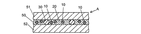
- connection structure of this embodiment is shown and it is a mimetic diagram of the section of a connection structure.
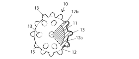
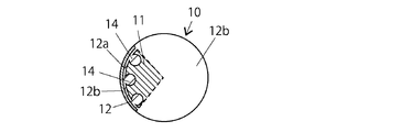
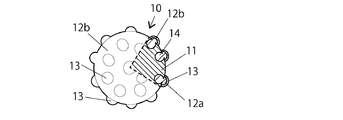
- grain is shown, and it is a schematic diagram of the external appearance and partial cross-section. It shows another example of the structure of the metal atom-containing particles, and is a schematic view of the appearance and partial cross-sectional structure. It shows another example of the structure of the metal atom-containing particles, and is a schematic view of the appearance and partial cross-sectional structure. It shows another example of the structure of the metal atom-containing particles, and is a schematic view of the appearance and partial cross-sectional structure.
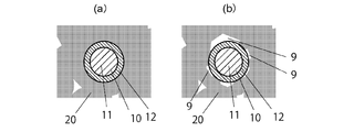
- (A) is a schematic diagram of the cross-sectional structure of the contact bonding layer in the connection structure of this embodiment
- (b) is a schematic diagram of the cross-section structure of the contact bonding layer in the conventional connection structure.
- FIG. 1 shows an example of the connection structure of the present embodiment, and schematically shows a cross-sectional structure of the connection structure.
- connection structure includes an adhesive layer including metal atom-containing particles and a sintered body of metal particles, and the metal atom-containing particles and the sintered body are in contact with each other through a chemical bond.
- the adhesive layer 5% or more of the outer peripheral length of the metal atom-containing particles is in contact with the sintered body.
- connection structure of the present embodiment has a large contact area of the metal atom-containing particles with the sintered metal particles, even if stress is applied to the connection structure, warpage and cracks are unlikely to occur in the connection structure. . Thereby, the connection structure can have excellent durability.
- first connection target member 51 includes a first connection target member 51, a second connection target member 52, and an adhesive layer 50 connecting the first and second connection target members.
- the first connection target member 51 and the second connection target member 52 are connected by the adhesive layer 50.
- the adhesive layer 50 is formed including the metal atom-containing particles 10 and the sintered body 20 of metal particles. Further, like the connection structure A of the present embodiment, the adhesive layer 50 can include gap control particles 30.
- the particle diameter of the gap control particles 30 is the same as the thickness of the adhesive layer 50, so to speak, it can serve as a spacer between the first connection target member 51 and the second connection target member 52.
- the gap control particles 30 can be, for example, known conductive particles, but are not limited thereto.
- connection target members 51 and 52 include electronic components such as semiconductor chips, capacitors and diodes, and electronic components such as printed boards, flexible printed boards, glass epoxy boards and glass boards.
- electronic components such as semiconductor chips, capacitors and diodes
- electronic components such as printed boards, flexible printed boards, glass epoxy boards and glass boards.
- the connection target members 51 and 52 are preferably electronic components.
- connection structure A is preferably a semiconductor device.
- the type of metal atom-containing particles is not particularly limited as long as it can form a chemical bond with the sintered body of metal particles.
- the metal atom-containing particles include base particles and metal portions disposed on the surfaces of the base particles.
- the metal atom-containing particles can easily form a chemical bond, particularly a metal bond, with the sintered body of the metal particles, and more specifically, the metal portion on the surface of the metal atom-containing particle and the sintered body of the metal particles.
- a so-called solid solution can be formed, whereby the metal atom-containing particles and the sintered body are more strongly joined to further suppress the occurrence of warpage and cracks in the connection structure.
- the type of the substrate particles is not particularly limited, and examples thereof include resin particles, inorganic particles excluding metal particles, organic-inorganic hybrid particles, and metal particles.
- the substrate particles are preferably resin particles, inorganic particles excluding metal particles, or organic-inorganic hybrid particles.
- the substrate particles are resin particles
- various organic materials are suitably used as a material for forming the resin particles.
- examples of such materials include polyolefin resins such as polyethylene, polypropylene, polystyrene, silicone resin, polyvinyl chloride, polyvinylidene chloride, polyisobutylene, and polybutadiene; acrylic resins such as polymethyl methacrylate and polymethyl acrylate; and polyalkylene terephthalate.
- the resin particles can also be obtained by polymerizing one or more kinds of various polymerizable monomers having an ethylenically unsaturated group.
- various polymerizable monomers having an ethylenically unsaturated group it is possible to design and synthesize resin particles having physical properties at the time of compression suitable for anisotropic conductive materials.
- the hardness of the base particle can be easily controlled within a suitable range.
- the material of the resin particles is preferably a polymer obtained by polymerizing one or more polymerizable monomers having a plurality of ethylenically unsaturated groups.
- the monomer having an ethylenically unsaturated group may be a non-crosslinkable monomer and / or a crosslinkable monomer.
- (meth) acryl means one or both of “acryl” and “methacryl”
- (meth) acrylate means one or both of “acrylate” and “methacrylate”. means.
- non-crosslinkable monomer examples include, as vinyl compounds, styrene monomers such as styrene, ⁇ -methylstyrene, chlorostyrene; methyl vinyl ether, ethyl vinyl ether, n-propyl vinyl ether, 1,4-butane.
- Vinyl ethers such as diol divinyl ether, cyclohexane dimethanol divinyl ether, and diethylene glycol divinyl ether; vinyl acid acetates such as vinyl acetate, vinyl butyrate, vinyl laurate, and vinyl stearate; halogen-containing simple substances such as vinyl chloride and vinyl fluoride
- a (meth) acrylic compound methyl (meth) acrylate, ethyl (meth) acrylate, propyl (meth) acrylate, butyl (meth) acrylate, 2-ethylhexyl (meth) acrylate, lauryl Alkyl (meth) acrylates such as (meth) acrylate, cetyl (meth) acrylate, stearyl (meth) acrylate, cyclohexyl (meth) acrylate, isobornyl (meth) acrylate; 2-hydroxyethyl (meth) acrylate, glycerol (
- crosslinkable monomer examples include vinyl monomers such as vinyl compounds such as divinylbenzene, 1,4-divinyloxybutane and divinylsulfone; (meth) acrylic compounds such as tetramethylolmethanetetra ( (Meth) acrylate, tetramethylolmethane tri (meth) acrylate, tetramethylolmethane di (meth) acrylate, trimethylolpropane tri (meth) acrylate, dipentaerythritol hexa (meth) acrylate, dipentaerythritol penta (meth) acrylate, glycerol Tri (meth) acrylate, glycerol di (meth) acrylate, (poly) ethylene glycol di (meth) acrylate, (poly) propylene glycol di (meth) acrylate, (poly) tetramethyleneglycol Polyfunctional (meth) acrylates
- crosslinkable and non-crosslinkable monomers are not limited to the monomers listed above, but may be other polymerizable monomers, for example, known polymerizable monomers.
- the resin particles can be obtained by polymerizing the polymerizable monomer having an ethylenically unsaturated group by a known method. Examples of this method include suspension polymerization in the presence of a radical polymerization initiator, and polymerization by swelling monomers together with a radical polymerization initiator using non-crosslinked seed particles (so-called seed weight). Legal). Conditions for these polymerization methods are not particularly limited, and known conditions can be widely applied.
- the substrate particles are inorganic particles or organic-inorganic hybrid particles excluding metal particles
- examples of the inorganic material that is a material of the substrate particles include silica and carbon black. This inorganic substance is preferably not a metal.
- the particles formed from the silica are not particularly limited. For example, after forming a crosslinked polymer particle by hydrolyzing a silicon compound having two or more hydrolyzable alkoxysilyl groups, firing may be performed as necessary. The particle
- the organic / inorganic hybrid particles include organic / inorganic hybrid particles formed of a crosslinked alkoxysilyl polymer and an acrylic resin.
- a resin containing polyrotaxane can be given as another example of the material of the base material particles.
- the polyrotaxane refers to a structure in which a chain polymer is formed through an opening of a cyclic molecule.
- the kind of polyrotaxane is not specifically limited, For example, a well-known polyrotaxane is mentioned.
- the polyrotaxane is preferably a crosslinked body.
- a structure in which a cyclic molecule in a polyrotaxane and a cyclic molecule in another polyrotaxane are crosslinked with a polymer chain is preferable.
- the flexibility of the base particles is increased, so that the stress relaxation effect is easily exhibited, and thereby, it is easy to suppress the occurrence of cracks and warpage of the connection structure.
- the kind is not specifically limited, For example, a well-known crosslinked polyrotaxane is mentioned.
- the polyrotaxane can be produced by, for example, a known method.
- a polyrotaxane having a crosslinked structure is produced by reacting a polyrotaxane having a cyclic molecule having a polymerizable functional group with a mixture of a polymerizable monomer. This reaction can be performed by, for example, a known method.
- the type of polyrotaxane having a cyclic molecule having a polymerizable functional group is not particularly limited. Specific examples include “Celum (registered trademark) Superpolymer SM3405P”, “Celum (registered trademark) Key Mixture SM3400C”, and “Celum (registered trademark) Superpolymer, commercially available from Advanced Soft Materials Co., Ltd. “SA3405P”, “Celum® Super Polymer SA2405P”, “Celum® Key Mixture SA3400C”, “Celum® Key Mixture SA2400C”, “Celum® Superpolymer SA3405P”, “ CELUM (registered trademark) superpolymer SA2405P "and the like.
- the average particle diameter of the substrate particles is not particularly limited, but can be, for example, less than 1 ⁇ 2 of the thickness of the adhesive layer in the connection structure.
- the average particle diameter of the substrate particles is as described above, cracks and warpage of the adhesive layer are unlikely to occur, and a decrease in the adhesive force of the adhesive layer is unlikely to occur.
- the average particle diameter of the base particles is preferably 0.1 ⁇ m or more and 55 ⁇ m or less. In this case, cracks and warpage of the connection structure in the cooling / heating cycle are unlikely to occur, and the adhesive force of the adhesive layer is hardly reduced even after the cooling / heating cycle test.
- the average particle diameter of the substrate particles is preferably 0.5 ⁇ m or more, more preferably 1 ⁇ m or more, and preferably 40 ⁇ m or less, more preferably 10 ⁇ m or less, and particularly preferably 6 ⁇ m or less.
- the average particle diameter of the substrate particles can be the same as the thickness of the adhesive layer.
- the metal atom-containing particles can also play the role of the gap control particles 30 described with reference to FIG.
- the above-mentioned average particle diameter of the base particles means the diameter when the shape is a true sphere, and means the average value of the maximum diameter and the minimum diameter when the shape is a shape other than the true sphere.
- the average particle diameter of the substrate particles means an average value obtained by observing the substrate particles with a scanning electron microscope and measuring the particle diameters of 50 randomly selected substrate particles with calipers.
- covered with another material (for example, metal part) as mentioned above also includes the coating layer.
- the coefficient of variation (CV value) of the particle diameter of the substrate particles is, for example, 50% or less.
- the coefficient of variation (CV value) is expressed by the following equation.
- CV value (%) ( ⁇ / Dn) ⁇ 100 ⁇ : standard deviation of particle diameter of particles
- Dn average value of particle diameter of particles
- the CV value of the particle diameter of the base particles is preferably 40%. Below, more preferably 30% or less.
- the lower limit of the CV value of the particle diameter of the substrate particles is not particularly limited.
- the CV value may be 0% or more, 5% or more, 7% or more, or 10% or more.
- the hardness of the substrate particles is not particularly limited, and is, for example, 10 N / mm 2 or more and 3000 N / mm 2 or less at a 10% K value.
- 10% K value is preferably 100 N / mm 2 or more, more preferably 1000 N / mm 2 or more, preferably 2500N / mm 2 or less, particularly preferably is less than or equal to 2000N / mm 2.
- the 10% K value referred to here is a compression elastic modulus when the substrate particles are compressed by 10%. It can be measured as follows. First, using a micro-compression tester, base material particles are compressed under a condition that a smooth tester end face of a cylinder (diameter 50 ⁇ m, made of diamond) is loaded at 25 ° C. and a maximum test load 20 mN over 60 seconds. The load value (N) and compression displacement (mm) at this time are measured. From the measured value obtained, the compression elastic modulus can be obtained by the following formula.
- the base particles preferably have 100 or less aggregated particles per 1 million particles.
- the agglomerated particles are particles in which one particle is in contact with at least one other particle.
- 1 million base particles include 3 particles in which 3 particles are aggregated (aggregates of 3 particles)
- the aggregated particles per 1 million base particles The number is nine.
- a method of measuring the aggregated particles a method of counting aggregated particles using a microscope set with a magnification so that about 50,000 particles are observed in one field of view, and measuring aggregated particles as a total of 20 fields of view, etc. Is mentioned.
- the substrate particles preferably have a thermal decomposition temperature of 200 ° C. or higher.
- the thermal decomposition temperature of the base particles is preferably 220 ° C. or higher, more preferably 250 ° C. or higher, and further preferably 300 ° C. or higher.
- a base particle has the below-mentioned coating layer, let temperature which thermally decomposes first among base material particle and a coating layer be the thermal decomposition temperature of base material particle.
- a metal part may be disposed on the surface of the base particle.
- the metal part is present so as to cover the surface of the base particle.
- the metal part is formed of a material containing metal.
- the metal include gold, silver, tin, copper, copper, germanium, indium, palladium, tellurium, thallium, bismuth, zinc, arsenic, selenium, iron, lead, ruthenium, aluminum, cobalt, titanium, antimony, and cadmium. , Silicon, nickel, chromium, platinum, rhodium and the like.
- the metal part may be any one of these metals, or may include two or more. Further, the metal part may be an alloy of two or more metals among the metals exemplified above.
- the metal is contained in an amount of 50% by mass or more, preferably 80% by mass or more, more preferably 90% by mass or more, and particularly preferably 99% by mass or more with respect to the total mass of the metal part. Moreover, the metal part may be formed only with the metal.
- the metal part preferably has a total amount of nickel, chromium, platinum and rhodium of 30% by mass or less based on the total mass of the metal part.
- the total amount of the nickel, chromium, platinum and rhodium is within the above range with respect to the total mass of the metal part, metal diffusion occurs when the particles constituting the sintered body, in particular, the sintered body are silver. As a result, the metal atom-containing particles are more easily brought into contact with the sintered body.
- the total amount of nickel, chromium, platinum and rhodium is preferably 25% by mass or less, more preferably 20% by mass or less, still more preferably 10% by mass or less, and particularly preferably 0% by mass with respect to the total mass of the metal part. It is. In the case where the total amount of nickel, chromium, platinum and rhodium in the metal part is within the above ranges with respect to the total mass of the metal part, the metal atom-containing particles are particularly likely to come into contact with the sintered body.
- the metal portion is made of gold, silver, tin, copper, germanium, indium, palladium, tellurium, thallium, bismuth, zinc, arsenic, selenium, and an alloy containing at least one of these metal elements. It is preferable to include one or more selected from the group. In this case, the metal atom-containing particles and the sintered body of the metal particles are more likely to come into contact, and the warpage and cracks of the connection structure can be further suppressed.
- Particularly preferred metal part is to contain a metal having a thermal conductivity of 200 W / m ⁇ K or more.
- a metal having a thermal conductivity of 200 W / m ⁇ K or more When such a metal is included, the occurrence of warping and cracks in the connection structure can be further suppressed, and heat dissipation can be enhanced.
- Examples of such a metal include one selected from the group consisting of gold, silver, and copper.
- the metal part may be formed of one layer or may be formed of a plurality of layers.
- the metal part preferably has a so-called multilayer structure formed of a plurality of layers.
- the metal contained in each layer may be different.
- the metal part can be formed in a two-layer structure.
- FIG. 2 schematically shows the appearance of metal atom-containing particles having a metal portion formed in a two-layer structure.
- the portion surrounded by the broken line in FIG. 2 is shown broken.
- the metal part 12 includes metal particles 11 and metal parts 12.
- the metal part 12 is disposed so as to cover the surface of the base particle 11.
- the metal part 12 is formed in a two-layer structure with a first metal part 12a and a second metal part 12b, the first metal part 12a being on the inside and the second metal part 12b being on the outside. It is arranged. That is, the first metal part 12a is in contact with the surface of the base particle 11, and the second metal part 12b is present so as to cover the surface of the first metal part 12a.
- the first metal part 12a and the second metal part 12b are made of gold, silver, and copper. It is particularly preferable to include one or more selected.
- the 1st metal part 12a contains copper
- the 2nd metal part 12b contains silver.
- the contact area with the metal sintered body is likely to be larger, and the metal sintered body is easily contacted.
- the 1st metal part 12a is copper, since the usage-amount of silver of the 2nd metal part 12b can be reduced, it becomes advantageous economically.
- the thickness of the metal part is preferably 0.5 nm or more, more preferably 10 nm or more, preferably 10 ⁇ m or less, more preferably 1 ⁇ m or less, More preferably, it is 500 nm or less, Most preferably, it is 300 nm or less.
- the thickness of the metal part is not less than the above lower limit and not more than the above upper limit, the metal atom-containing particles are more easily dispersed more uniformly in the sintered body of the metal particles, and more easily contacted with the sintered body (that is, Since the contact area of the metal atom-containing particles with respect to the sintered body is increased), warping and cracking of the connection structure can be further suppressed.
- the thickness of the metal part means the total thickness of each layer, that is, the thickness of the entire metal part.
- the method for forming the metal part on the surface of the base material particles is not particularly limited.
- a method for forming a metal part for example, a method by electroless plating, a method by electroplating, a method by physical vapor deposition, and a method of coating the surface of base particles with metal powder or a paste containing metal powder and a binder Etc. From the viewpoint that the formation of the metal part is simple, a method by electroless plating is preferred.
- Examples of the method by physical vapor deposition include methods such as vacuum vapor deposition, ion plating, and ion sputtering.
- the metal part When the metal part has a multilayer structure, the metal part can be formed by the same method. For example, by adopting the above-described method for forming a metal part, a first layer metal part is formed on the surface of the substrate particles, and further layers are sequentially formed on the surface of the first layer. A metal part of the structure can be formed.
- the form of the metal part mentioned above is only an example, and the metal atom-containing particle may include a metal part having a form other than the above.
- the metal part may have a plurality of protrusions on the outer surface.
- FIG. 3 schematically shows the appearance of metal atom-containing particles having a metal portion having a plurality of protrusions on the outer surface.
- FIG. 3 schematically shows the appearance of metal atom-containing particles having a metal portion having a plurality of protrusions on the outer surface.
- FIG. 3 schematically shows the appearance of metal atom-containing particles having a metal portion having a plurality of protrusions on the outer surface.
- FIG. 3 schematically shows the appearance of metal atom-containing particles having a metal portion having a plurality of protrusions on the outer surface.
- the metal part 12 is disposed so as to cover the surface of the base particle 11.
- the metal part 12 is formed in a two-layer structure with a first metal part 12a and a second metal part 12b, the first metal part 12a being on the inside and the second metal part 12b being on the outside. It is arranged. That is, the first metal part 12a is in contact with the surface of the base particle 11, and the second metal part 12b is present so as to cover the surface of the first metal part 12a.
- the configuration of the metal portion 12 formed in a two-layer structure can be the same as the configuration of the metal atom-containing particle 10 in the form of FIG. 2 described above.
- a plurality of protrusions 13 are formed on the outer surface of the metal part 12.
- the protrusion 13 is formed so as to protrude from the base portion to the surface side with the base portion as a bottom surface.
- the presence of such a plurality of protrusions 13 makes it easier for the metal atom-containing particles and the sintered body of the metal particles to come into contact with each other, and as a result, the warpage of the connection structure and the generation of cracks are easily suppressed. .
- the position where the base is formed is on the surface of the metal part 12.
- the method for forming the protrusion is not particularly limited, and for example, a known method can be adopted. Specifically, after a core material is attached to the surface of the substrate particles, a metal portion is formed by electroless plating, and after the metal portion is formed by electroless plating on the surface of the substrate particles, the core material is formed. And a method of forming a metal part by electroless plating. Furthermore, as another method for forming the protrusion, after forming the first metal part on the surface of the base particle, a core substance is arranged on the first metal part, and then the second metal part is formed. Examples thereof include a method of forming a metal part, and a method of adding a core substance in the middle of forming the metal part on the surface of the base particle.
- a core substance is added to the dispersion of the base particle, and the core substance is applied to the surface of the base particle by, for example, van der Waals force.
- examples thereof include a method of accumulating and adhering, and a method of adding a core substance to a container containing base particles and attaching the core substance to the surface of the base particles by a mechanical action such as rotation of the container.
- a method in which the core substance is accumulated on the surface of the substrate particles in the dispersion and attached is preferable. If the core substance is embedded in the metal part, the protrusion can be easily formed on the outer surface of the metal part.
- the material of the core substance includes a conductive substance and a non-conductive substance.
- the conductive substance include metals, metal oxides, conductive non-metals such as graphite, and conductive polymers.
- the conductive polymer include polyacetylene.
- the nonconductive material include silica, alumina, and zirconia.
- a metal is preferable from a viewpoint that it becomes easier to contact a sintered compact.
- the core substance is preferably metal particles.
- the metal in this case include the various metals described above that can form the metal portion. More preferably, it is the same as the kind of metal constituting the outermost layer of the metal part. Therefore, it is particularly preferable that the metal constituting the protrusion includes one or more selected from the group consisting of gold, silver, and copper.
- the shape of the core substance is not particularly limited.
- the shape of the core substance is preferably a lump.
- Examples of the core substance include a particulate lump, an agglomerate in which a plurality of fine particles are aggregated, and an irregular lump.
- the average diameter (average particle diameter) of the core substance is preferably 0.001 ⁇ m or more, more preferably 0.05 ⁇ m or more, preferably 0.9 ⁇ m or less, more preferably 0.2 ⁇ m or less.
- the average diameter (average particle diameter) of the core substance indicates a number average diameter (number average particle diameter).
- the average diameter of the core material is obtained by observing 50 arbitrary core materials with an electron microscope or an optical microscope and calculating an average value. When measuring the average diameter of the core substance in the metal atom-containing particles, for example, the average diameter of the core substance can be measured as follows.
- An embedded resin for inspecting metal atom-containing particles is prepared by adding and dispersing metal atom-containing particles in “Technobit 4000” manufactured by Kulzer so that the content is 30% by weight.
- a cross section of the metal atom-containing particles is cut out using an ion milling device (“IM4000” manufactured by Hitachi High-Technologies Corporation) so as to pass near the center of the dispersed metal atom-containing particles in the embedded resin for inspection.
- IM4000 manufactured by Hitachi High-Technologies Corporation
- FE-SEM field emission scanning electron microscope
- the diameter of the core substance in the obtained metal atom-containing particles is measured, and is arithmetically averaged to obtain the average diameter of the core substance.
- the shape of the protrusion is not particularly limited.
- the protrusion may be formed in a spherical or elliptical cross section, or may be formed in a needle shape that becomes sharper toward the tip.
- the shape of such a protrusion can be controlled according to, for example, the material of the core substance.
- the average height of the protrusions can be 1 nm or more and 1000 nm or less, preferably 5 nm or more, more preferably 50 nm or more, preferably 900 nm or less, more preferably 500 nm or less.
- the average height of the protrusions is not less than the above lower limit and not more than the above upper limit, the metal atom-containing particles are more likely to come into contact with the sintered body.
- the average height of the protrusions can be measured as follows, for example.
- An embedded resin for inspecting metal atom-containing particles is prepared by adding and dispersing metal atom-containing particles in “Technobit 4000” manufactured by Kulzer so that the content is 30% by weight.
- a cross section of the metal atom-containing particles is cut out using an ion milling device (“IM4000” manufactured by Hitachi High-Technologies Corporation) so as to pass near the center of the dispersed metal atom-containing particles in the embedded resin for inspection.
- IM4000 manufactured by Hitachi High-Technologies Corporation
- FE-SEM field emission scanning electron microscope
- the image magnification is set to 50,000 times, 20 metal atom-containing particles are randomly selected, and the protrusion 50 of each metal atom-containing particle is selected. Observe the pieces.
- the height from the base, which is the bottom surface of the protrusion, to the top of the protrusion is defined as the height of the protrusion, and the arithmetic average
- the average diameter of the base of the protrusion can be 3 nm or more and 5000 nm or less, preferably 50 nm or more, more preferably 80 nm or more, preferably 1000 nm or less, more preferably 500 nm or less.
- the average diameter of the base here is the same as the method for measuring the average height of the protrusions described above, and the protrusions of 20 metal atom-containing particles randomly selected by FE-SEM observation using an embedded resin were used. Each of them is observed, the distance between both ends of each base is measured, and the value obtained by arithmetically averaging them is said.
- the protrusion can occupy 30% or more in the total surface area of 100% of the outer surface of the metal part.
- the metal atom-containing particles are more likely to come into contact with the sintered body.
- the area occupied by the protrusions on the outer surface of the metal part can be measured, for example, as follows. First, an orthographic plan view of metal atom-containing particles is taken with a field emission scanning electron microscope (FE-SEM). A 6000 ⁇ photograph taken with the FE-SEM is analyzed with a commercially available image analysis software.
- FE-SEM field emission scanning electron microscope
- the area of the protrusion (area in plan view) is obtained, and the ratio of the area of the protrusion to the area of the metal atom-containing particles is defined as the area occupied by the protrusion.
- the area occupied by the protrusions on the outer surface of the metal part is determined.
- a base particle having a recess and a metal portion arranged on the surface of the base particle may be provided.
- a metal part can also be formed in the recess.
- FIG. 4 shows an example of a metal atom-containing particle 10 that includes a base particle 11 having a recess 14 and a metal portion 12 disposed on the surface of the base particle 11.
- 10 schematically shows the external appearance of 10.
- FIG. 4 shows the part enclosed with the broken line part.
- a plurality of recesses 14 are formed on the surface of the base particle 11.
- the metal part 12 is disposed so as to cover the surface of the base particle 11.
- the metal part 12 is formed in a two-layer structure with a first metal part 12a and a second metal part 12b, and the first metal part 12a is on the inner side and the second metal part 12b is on the inner side. Arranged outside. That is, the first metal part 12a is in contact with the surface of the base particle 11, and the second metal part 12b is present so as to cover the surface of the first metal part 12a.
- the configuration of the metal portion 12 formed in a two-layer structure can be the same as the configuration of the metal atom-containing particle 10 in the form of FIG. 2 described above.
- the metal part 12 is also formed on the surface of the recess 14. In the form of FIG. 4, a first metal portion 12 a is formed in the recess 14.
- the metal atom-containing particles in which the metal portion is formed on the surface of the base particle having a plurality of concave portions as described above in addition to the metal atom-containing particles and the sintered body of the metal particles being more easily contacted, The effect
- the metal atom-containing particles since the metal atom-containing particles have a recess, the metal atom-containing particles can easily follow deformation, and as a result, even if stress is applied to the connection structure, generation of warpage and Cracks are less likely to occur.
- the method for preparing the base particles having the recesses is not particularly limited.
- the recesses can be formed in the base particles by post-processing the above base particles.
- the formation method of the recess by the post-treatment is not particularly limited, and for example, a known method can be adopted. Specifically, a method of etching the surface of the substrate particles, a method of plasma treatment in an oxygen atmosphere, a method of ozone treatment and heat treatment, a method of humidification treatment, a method of heat treatment in vacuum, under pressure and humidification conditions Examples thereof include a heat treatment method, a wet treatment method using an oxidizing agent, and a physical treatment method using a ball mill.
- the average depth of the recess is not particularly limited.
- the average depth of the recesses can be 0.1% or more and 80% or less of the average radius of the base particles.
- the depth of a recessed part here refers to the distance from the surface of the spherical base material particle to the point which becomes the bottom face of a recessed part on the assumption that the base material particle which has a recessed part is spherical.
- each of the projections of 20 metal atom-containing particles randomly selected by FE-SEM observation using an embedded resin was observed in the same procedure as the above-described method for measuring the average height of the projections. A value obtained by arithmetically averaging the depth of each recess.
- FIG. 5 shows a further modification of the metal atom-containing particle 10 and schematically shows the appearance of the metal atom-containing particle.
- FIG. 5 shows a further modification of the metal atom-containing particle 10 and schematically shows the appearance of the metal atom-containing particle.
- the metal atom-containing particle 10 of FIG. 5 includes a base particle 11 having a plurality of recesses 14 and a metal part 12 disposed on the surface of the base particle 11, A plurality of protrusions 13 are formed.
- the metal part 12 is formed in a two-layer structure with a first metal part 12a and a second metal part 12b. That is, the metal atom-containing particle 10 in the form of FIG. 5 has the characteristics of both the metal atom-containing particles 10 of FIGS. 3 and 4.
- the presence of the plurality of protrusions 13 makes it easier for the metal atom-containing particle and the sintered body of the metal particle to come into contact with each other.
- the metal atom-containing particles can easily follow the deformation. Therefore, in the connection structure including the metal atom-containing particles 10 in the form of FIG. 5, the occurrence of warpage and cracks are particularly easily suppressed.
- the metal atom-containing particle 10 in the form of FIG. 5 is manufactured by the same method as the metal atom-containing particle 10 in the form of FIG. 3 except that the base particle 11 having a plurality of recesses 14 is used as the base particle 11. Can be done.
- the hardness of the metal atom-containing particles 10 is not particularly limited, for example, 10% K value 10 N / mm 2 or more and 6000 N / mm 2 or less. From the viewpoint of suppressing the generation of cracks and warpage of the connection structure further, 10% K value of the metal atom-containing particles 10 is preferably 100 N / mm 2 or more, more preferably 1000 N / mm 2 or more, preferably 5500N / mm 2 or less, particularly preferably 5000 N / mm 2 or less.
- the metal contained in the sintered body of metal particles is not particularly limited.
- the metal contained in the sintered body of metal particles includes gold, silver, tin, copper, germanium, indium, palladium, tellurium, thallium, bismuth, zinc, arsenic, selenium, and at least one of these metal elements. It is preferable to include at least one selected from the group consisting of alloys containing various metal elements. In this case, the metal atom-containing particles and the sintered body of the metal particles are more likely to come into contact, and the warpage and cracks of the connection structure can be further suppressed. It is particularly preferable that the metal contained in the sintered body of metal particles contains one or more selected from the group consisting of gold, silver and copper. Moreover, the sintered body of metal particles may be formed only of metal.
- the metal atom-containing particles exist so as to be embedded in the sintered body of metal particles.
- the metal atom-containing particles are present such that part or all of the surface thereof is in contact with the sintered body of metal particles.
- the metal atom-containing particles and the sintered body are in contact via chemical bonds.
- a metal bond is mentioned.
- the metal contained in the metal part or protrusion existing on the surface of the metal atom-containing particle and the metal contained in the sintered body form a solid solution. In this case, since the metal atom-containing particles and the sintered body are more firmly in contact with each other, even if stress is applied to the connection structure, generation of warpage and cracks are further less likely to occur.
- a part of the surface of the metal atom-containing particles may be in contact with the sintered body, or the entire surface of the metal atom-containing particles may be in contact with the sintered body.
- connection structure of the present embodiment 5% or more of the outer peripheral length of the metal atom-containing particles is in contact with the sintered body in the cross section of the adhesive layer.
- the surface area of the metal atom-containing particles it is preferable that 5% or more of the entire surface area of the metal atom-containing particles is in contact with the sintered body.
- FIG. 6 schematically shows a cross-sectional structure of the adhesive layer 50 in the connection structure according to the present embodiment.
- the adhesive layer 50 includes the metal atom-containing particles 10 and the sintered body 20.
- the metal atom-containing particle 10 is formed to have at least a base particle 11 and a metal part 12.
- most of the outer periphery of the metal atom-containing particle 10 (for example, 5% or more of the entire outer periphery is in contact with the sintered body 20. In this form, stress is applied to the connection structure. Even if it occurs, warping and cracking are less likely to occur.
- 10% or more of the outer peripheral length of the metal atom-containing particles is preferably in contact with the sintered body, more preferably 50% or more is in contact with the sintered body, and 90% It is particularly preferable that the above is in contact with the sintered body.
- the fact that the outer periphery of the metal atom-containing particles is in contact with the sintered body in the cross section of the adhesive layer can be confirmed, for example, by observation with a transmission electron microscope FE-TEM.
- the contact between the metal atom-containing particles and the sintered body can be confirmed, for example, as follows.
- a paste for sintering (bonding composition) is prepared by adding to and dispersing in a sintering material described later so that the content of the metal atom-containing particles is 5% by weight. Further, a power semiconductor element having a connection surface with Ni / Au plating is prepared as a first connection target member. As a second connection target member, an aluminum nitride substrate having a connection surface plated with Cu is prepared. On the 2nd connection object member, the said paste for sintering is apply
- the obtained laminate is preheated with a hot plate at 130 ° C. for 60 seconds, and then the laminate is heated at 300 ° C. for 3 minutes under a pressure of 10 MPa, so that the above-mentioned paste contained in the sintering paste
- the metal atom-containing particles are sintered to form a connection part including the sintered product and the metal atom-containing particles, and the first and second connection target members are joined by the sintered product, thereby connecting structure Get.
- connection structure is put in “Technobit 4000” manufactured by Kulzer and cured to produce an embedded resin for connection structure inspection.
- Mechanical polishing is performed so as to pass through the vicinity of the center of the connection structure in the inspection embedded resin, and a cross section of the metal atom-containing particles is cut out using an ion milling device ("IM4000” manufactured by Hitachi High-Technologies Corporation).
- the contact ratio between the outer periphery of the metal atom-containing particles and the sintered body can be calculated by automatic calculation or the like, and thereby the contact ratio can be quantified.
- the sintered body of metal particles can be formed, for example, by sintering a sintering material containing metal particles at a predetermined temperature.
- the metal particles contained in the sintering material may be single metal particles or metal compound particles.
- a metal compound is a compound containing a metal atom and atoms other than the metal atom.
- the metal compound examples include metal oxides, metal carbonates, metal carboxylates and metal complexes.
- the metal compound is preferably a metal oxide.
- the metal oxide is sintered after becoming metal particles by heating at the time of connection in the presence of a reducing agent.
- the metal oxide is a precursor of metal particles.
- the metal carboxylate particles include metal acetate particles.
- the metal contained in the metal particles and the metal compound is gold, silver, tin, copper, germanium, indium, palladium, tellurium, thallium, bismuth, zinc, arsenic, selenium, and at least one metal element of these metal elements It is preferable to include one or more selected from the group consisting of alloys containing. In this case, the metal atom-containing particles and the sintered body of the metal particles are more likely to come into contact, and the warpage and cracks of the connection structure can be further suppressed. It is particularly preferable that the metal contained in the sintered body of metal particles contains one or more selected from the group consisting of gold, silver and copper. When silver particles and silver oxide particles are used, the sintered body is more likely to come into stronger contact with the metal atom-containing particles. Examples of silver oxide include Ag 2 O and AgO.
- the average particle diameter of the metal particles is preferably 10 nm or more and 10 ⁇ m or less. Moreover, it is preferable to have 2 or more types of metal particles from which an average particle diameter differs from a viewpoint of improving the connection intensity
- the average particle diameter of the metal particles having a small average particle diameter is preferably 10 nm or more, and preferably 100 nm or less.
- the average particle diameter of the metal particles having a large average particle diameter is preferably 1 ⁇ m or more, and preferably 10 ⁇ m or less.
- the ratio of the amount of the metal particles having a small average particle diameter to the metal particles having a large average particle diameter is preferably 1/9 or more and 9 or less.
- the said average particle diameter is calculated
- the metal particles are preferably sintered by heating at less than 400 ° C.
- the temperature at which the metal particles are sintered (sintering temperature) is more preferably 350 ° C. or lower, and preferably 300 ° C. or higher.
- sintering temperature is more preferably 350 ° C. or lower, and preferably 300 ° C. or higher.
- the sintering material including the metal particles preferably contains a reducing agent.
- the reducing agent include alcohols (compounds having an alcoholic hydroxyl group), carboxylic acids (compounds having a carboxy group), amines (compounds having an amino group), and the like.
- the said reducing agent only 1 type may be used and 2 or more types may be used together.
- Alcohol is mentioned as said alcohol.
- the alcohols include, for example, ethanol, propanol, butyl alcohol, pentyl alcohol, hexyl alcohol, heptyl alcohol, octyl alcohol, nonyl alcohol, decyl alcohol, undecyl alcohol, dodecyl alcohol, tridecyl alcohol, tetradecyl alcohol.
- the alcohols are not limited to primary alcohol compounds, but secondary alcohol compounds, tertiary alcohol compounds, alkane diols, and alcohol compounds having a cyclic structure can also be used. Furthermore, as the alcohols, compounds having many alcohol groups such as ethylene glycol and triethylene glycol may be used. Moreover, you may use compounds, such as a citric acid, ascorbic acid, and glucose, as said alcohol.
- carboxylic acids examples include alkyl carboxylic acids. Specific examples of the carboxylic acids include butanoic acid, pentanoic acid, hexanoic acid, heptanoic acid, octanoic acid, nonanoic acid, decanoic acid, undecanoic acid, dodecanoic acid, tridecanoic acid, tetradecanoic acid, pentadecanoic acid, hexadecanoic acid, heptadecanoic acid , Octadecanoic acid, nonadecanoic acid and icosanoic acid.
- the carboxylic acids are not limited to primary carboxylic acid type compounds, but secondary carboxylic acid type compounds, tertiary carboxylic acid type compounds, dicarboxylic acids, and carboxyl compounds having a cyclic structure can also be used.
- Examples of the amines include alkylamines. Specific examples of the amines include butylamine, pentylamine, hexylamine, heptylamine, octylamine, nonylamine, decylamine, undecylamine, dodecylamine, tridecylamine, tetradecylamine, pentadecylamine, hexadecylamine, Examples include heptadecylamine, octadecylamine, nonadecylamine and icodecylamine.
- the amines may have a branched structure.
- Examples of amines having a branched structure include 2-ethylhexylamine and 1,5-dimethylhexylamine.
- the amines are not limited to primary amine compounds, and secondary amine compounds, tertiary amine compounds, and amine compounds having a cyclic structure can also be used.
- the reducing agent may be an organic substance having an aldehyde group, an ester group, a sulfonyl group, or a ketone group, or an organic substance such as a carboxylic acid metal salt. While the carboxylic acid metal salt is used as a precursor of metal particles, it also contains an organic substance, so that it is also used as a reducing agent for metal oxide particles.
- the content of the reducing agent is preferably 1 part by weight or more, more preferably 10 parts by weight or more, preferably 1000 parts by weight or less, more preferably 500 parts by weight or less, based on 100 parts by weight of the metal particles.
- the amount is preferably 100 parts by weight or less.
- connection temperature the sintering temperature of the metal atom-containing particles
- the particles tend to aggregate at the time of connection and voids are likely to occur at the connection part.
- the carboxylic acid metal salt By using the carboxylic acid metal salt, the carboxylic acid metal salt is not melted by heating at the time of connection.
- a metal compound containing an organic substance may be used as the reducing agent.
- the sintering material containing metal particles may include other materials.
- a resin component may be included in the sintering material. When the resin component is included, the occurrence of cracks, warpage, and peeling of the adhesive layer of the connection structure are suppressed.
- the resin component is not particularly limited.
- the resin component preferably includes a thermoplastic resin or a curable resin, and more preferably includes a curable resin.
- the curable resin include a photocurable resin and a thermosetting resin.
- the photocurable resin preferably contains a photocurable resin and a photopolymerization initiator.
- the thermosetting resin preferably contains a thermosetting resin and a thermosetting agent.
- the resin include known vinyl resins, thermoplastic resins, curable resins, thermoplastic block copolymers, and elastomers. As for the said resin, only 1 type may be used and 2 or more types may be used together.
- the sintering material containing metal particles may contain a dispersion medium.
- the dispersion medium include known solvents.
- the sintering material containing the metal particles may be a commercially available product. Specific examples include “CT2700” manufactured by Kyocera Chemical Co., “ASP295”, “ASP016”, “ASP043” manufactured by Heraeus, “LOCTITE ABLESTIK SSP2020” manufactured by Henkel, “H9890-6A” manufactured by NAMICS, and manufactured by Harima Chemicals. “NH-4000”, “NH-225D”, “NH-3000D”, “CM-3212”, “CR-3520” manufactured by Kaken Tech, “Arconano silver paste ANP-1” manufactured by Nippon Superior, etc. It is done.
- the content of the metal atom-containing particles is preferably 0.1% by weight or more, more preferably 1% by weight or more, preferably 20% by weight or less, more preferably 10% by weight or less.
- production of the crack of a connection structure and a curvature is further suppressed as content of a metal atom containing particle is more than the said minimum and below the said upper limit.
- the content of the metal particles is preferably larger than the content of the metal atom-containing particles, for example, more preferably 10% by weight or more, and still more preferably 20% by weight or more.
- the content of the metal particles is preferably 70% by weight or more, more preferably 80% by weight or more, preferably 98% by weight or less, more preferably 95% by weight or less.
- production of the crack of a connection structure and a curvature is further suppressed as content of the said metal atom containing particle
- the manufacturing method of the connection structure according to the present embodiment is not particularly limited.
- a mixture of the metal atom-containing particles and the above-described sintering material is disposed and laminated between the first connection target member and the second connection target member.
- Examples include a method of forming a body and heating and pressurizing the laminate. Thereby, the metal particles contained in the laminate are sintered, an adhesive layer in which the metal atom-containing particles are dispersed is formed in the sintered body, and the first connection target member and the second connection target member are bonded to each other. Connected by.
- connection structure of the present embodiment most of the surface of the metal atom-containing particles in the adhesive layer is in contact with the sintered body, and since the contact is strong, pressure mounting is not necessarily required, so-called It becomes possible to mount without pressure. Therefore, the connection structure can be manufactured advantageously in terms of the process.
- the metal atom-containing particles described above are suitable as materials for assembling the connection structure because the contact area of the metal particles with the sintered body can be increased in the adhesive layer included in the connection structure. Therefore, according to the metal atom-containing particles, it is possible to provide a connection structure in which warpage and cracks are unlikely to occur.
- the metal atom-containing particles are also suitable as a constituent component of the bonding composition.
- a bonding composition can be prepared by combining the metal atom-containing particles and the metal particles for sintering described above.
- the above bonding composition contains metal atom-containing particles and metal particles, it is suitable as a material for assembling the connection structure. Specifically, the bonding composition is applied between the first connection target member and the second connection target member, and the metal particles in the bonding composition are sintered to bond the metal atom-containing particles. A layer may be formed.
- the bonding composition can be prepared by mixing metal atom-containing particles and metal particles in a predetermined blending amount.
- a bonding composition can be prepared by mixing the above-described metal atom-containing particles and a sintering material containing metal particles.
- the mixing method of a metal atom containing particle and a metal particle is not specifically limited, A well-known mixing method is employable.
- the mixing ratio of the metal atom-containing particles and the metal particles is not particularly limited.
- the content of the metal atom-containing particles is preferably 0.1% by weight or more, more preferably 1% by weight or more, preferably 20% by weight or less. More preferably, it is 10% by weight or less.
- the content of the metal atom-containing particles is not less than the above lower limit and not more than the above upper limit, the metal particles can be sintered more densely, and the contact area of the metal atom-containing particles with the sintered body is increased.
- the content of the metal particles is preferably 70% by weight or more, more preferably 80% by weight or more, preferably 98% by weight or less, more preferably 95% by weight or less.
- the metal particles can be sintered more densely.
- the content of the resin component is preferably 1% by weight or more, more preferably 5% by weight or more in 100% by weight of the component excluding the dispersion medium of the bonding composition. , Preferably 20% by weight or less, more preferably 15% by weight or less.
- the content of the resin component is not less than the lower limit and not more than the upper limit, the metal particles can be sintered more densely.
- Example 1 As the base particle S1, divinylbenzene copolymer resin particles (“Micropearl SP-203” manufactured by Sekisui Chemical Co., Ltd.) having a particle diameter of 3.0 ⁇ m were prepared.
- divinylbenzene copolymer resin particles (“Micropearl SP-203” manufactured by Sekisui Chemical Co., Ltd.) having a particle diameter of 3.0 ⁇ m were prepared.
- the base material particles S1 After dispersing 10 parts by weight of the base material particles S1 in 100 parts by weight of an alkaline solution containing 5% by weight of a palladium catalyst solution using an ultrasonic disperser, the base material particles S1 were taken out by filtering the solution. Subsequently, the base particle S1 was added to 100 parts by weight of a 1% by weight dimethylamine borane solution to activate the surface of the base particle S1. The substrate particles S1 whose surface was activated were sufficiently washed with water, and then added to 500 parts by weight of distilled water and dispersed to obtain a suspension (A1).
- Suspension (A1) was put in a solution containing 20 g / L of copper sulfate and 30 g / L of ethylenediaminetetraacetic acid to obtain a particle mixture (B1).
- an electroless copper plating solution a mixed solution containing 250 g / L of copper sulfate, 150 g / L of ethylenediaminetetraacetic acid, 100 g / L of sodium gluconate, and 50 g / L of formaldehyde is adjusted to pH 10.5 with ammonia.
- a plating solution (C1) was prepared.
- a silver plating solution (D1) prepared by adjusting a mixed solution containing 30 g / L of silver nitrate, 100 g / L of succinimide, and 20 g / L of formaldehyde to pH 8.0 with aqueous ammonia is prepared. did.
- the copper plating solution (C1) was gradually dropped into the dispersed particle mixture (B1) adjusted to 55 ° C. to perform electroless copper plating.
- the dropping rate of the copper plating solution (C1) was 30 mL / min, the dropping time was 30 minutes, and electroless copper plating was performed. In this way, a particle mixed liquid (E1) containing particles having a copper metal part as the first metal part on the surface of the resin particle was obtained.
- the particle mixture liquid (E1) was filtered to take out the particles and washed with water to obtain particles in which the copper metal part was disposed on the surface of the base particle S1.
- the particles were sufficiently washed with water, and then added to 500 parts by weight of distilled water and dispersed to obtain a particle mixture (F1).
- the silver plating solution (D1) was gradually dropped into the dispersed particle mixture (F1) adjusted to 60 ° C. to perform electroless silver plating.
- the dropping rate of the silver plating solution (D1) was 10 mL / min, the dropping time was 30 minutes, and electroless silver plating was performed.
- the particles are taken out by filtration, washed with water, and dried to obtain metal atom-containing particles comprising copper and a silver metal part (total thickness of the metal part: 0.1 ⁇ m) on the surface of the base particle S1. It was.
- Example 2 The base particle S1 of Example 1 was prepared. Also, a suspension (A2) similar to the suspension (A1) of Example 1 was prepared.
- Suspension (B2) was put in a solution containing 20 g / L of copper sulfate and 30 g / L of ethylenediaminetetraacetic acid to obtain a particle mixture (C2).
- the copper plating solution (D2) was gradually dropped into the dispersed particle mixture (C2) adjusted to 55 ° C. to perform electroless copper plating.
- the dropping rate of the copper plating solution (D2) was 30 mL / min, the dropping time was 30 minutes, and electroless copper plating was performed.
- positioned as the 1st metal part on the surface of the resin particle and the metal part which has protrusion on the surface was obtained.
- the particles are taken out and washed with water, whereby a copper metal part is disposed on the surface of the base particle S1, and a metal part having a protrusion on the surface is provided. Particles were obtained. The particles were sufficiently washed with water, and then added to 500 parts by weight of distilled water and dispersed to obtain a particle mixture (G2).
- the silver plating solution (E2) was gradually added dropwise to the dispersed particle mixture (G2) adjusted to 60 ° C. to perform electroless silver plating.
- the dropping rate of the silver plating solution (E2) was 10 mL / min, the dropping time was 30 minutes, and electroless silver plating was performed.
- the particles are taken out by filtration, washed with water, and dried, so that the copper and silver metal parts (thickness of the whole metal part in the part having no protrusions: 0.1 ⁇ m) are arranged on the surface of the base particle S1.
- metal atom-containing particles having a metal part having a plurality of protrusions on the surface were obtained.
- Example 3 Metal atom-containing particles were obtained in the same manner as in Example 2 except that the metal nickel particle slurry was changed to alumina particle slurry (average particle diameter 150 nm).
- Example 4 Metal atom-containing particles were obtained in the same manner as in Example 2 except that the metal nickel particle slurry was changed to a copper particle slurry (average particle diameter 150 nm).
- Example 5 The suspension (A1) obtained in Example 1 was put in a solution containing nickel sulfate 40 ppm, trisodium citrate 2 g / L, and aqueous ammonia 10 g / L to obtain a particle mixture (B5).
- a plating solution (C5) for forming an acicular protrusion which is an electroless copper-nickel-phosphorus alloy plating solution prepared by adjusting a mixed solution containing polyethylene glycol 1000 (molecular weight: 1000) 5 mg / L as an agent to pH 10.0 with ammonia water. ) was prepared.
- a silver plating solution (D5) prepared by adjusting a mixed solution of silver nitrate 30 g / L, succinimide 100 g / L, and formaldehyde 20 g / L to pH 8.0 with aqueous ammonia was prepared. .
- the acicular protrusion-forming plating solution (C5) was gradually dropped into the dispersed particle mixture (B5) adjusted to 70 ° C. to form acicular protrusions.
- Electrolytic copper-nickel-phosphorus alloy plating was performed at a dropping rate of the needle-like projection forming plating solution (C5) of 40 mL / min and a dropping time of 60 minutes (needle-like projection formation and copper-nickel-phosphorus alloy plating). Process). Thereafter, the particles are taken out by filtration, and a particle (E5) having a metal part in which a copper-nickel-phosphorus alloy metal part is disposed on the surface of the base particle S1 and having a convex part (precipitation protrusion) on the surface. Got.
- the particles (E5) were added to 500 parts by weight of distilled water and dispersed to obtain a suspension (F5).
- the particles are taken out and washed with water, whereby the copper-nickel-phosphorus alloy metal part is arranged on the surface of the base particle A, and the surface is needle-like.
- grains provided with the metal part which has a convex part were obtained.
- the particles were sufficiently washed with water, and then added to 500 parts by weight of distilled water and dispersed to obtain a particle mixture (G5).
- the silver plating solution (D5) was gradually dropped into the dispersed particle mixture (G5) adjusted to 60 ° C. to perform electroless silver plating.
- the dropping rate of the silver plating solution (D5) was 10 mL / min, the dropping time was 30 minutes, and electroless silver plating was performed.
- the particles are taken out by filtration, washed with water, and dried to obtain a copper-nickel-phosphorus alloy part and a silver metal part on the surface of the base particle S1 (the thickness of the entire metal part in the part having no protrusions: 0). .1 ⁇ m), and metal atom-containing particles having a metal part having a plurality of needle-like protrusions on the surface were obtained.
- Example 6 The suspension (A1) obtained in Example 1 was put into a solution containing 500 ppm of potassium cyanide, 10 g / L of potassium cyanide and 10 g / L of potassium hydroxide to obtain a particle mixture (B6).
- the electroless silver plating solution (C6) was gradually dropped into the dispersed particle mixture (B6) adjusted to 80 ° C. to form needle-like protrusions.
- the dropping rate of the electroless silver plating solution (C6) was 10 mL / min, the dropping time was 60 minutes, and electroless silver plating was performed (acicular protrusion formation and silver plating step). Thereafter, the particles are taken out by filtration, washed with water, and dried, whereby a silver metal part (the thickness of the whole metal part in the part where there is no protrusion: 0.1 ⁇ m) is arranged on the surface of the resin particles, Metal atom-containing particles provided with a silver metal part having a plurality of needle-like protrusions were obtained.
- Example 7 The suspension (B2) obtained in Example 2 was put in a solution containing 20 g / L of copper sulfate and 30 g / L of ethylenediaminetetraacetic acid to obtain a particle mixture (C7).
- a plating solution (D7) was prepared as an electroless copper plating solution.
- the copper plating solution (D7) was gradually added dropwise to the dispersed particle mixture (C7) adjusted to 55 ° C. to perform electroless copper plating.
- the dropping rate of the copper plating solution (D7) was 30 mL / min, the dropping time was 30 minutes, and electroless copper plating was performed. Thereafter, the particles are taken out by filtration, and in this way, a particle mixed liquid (F7) containing particles in which the copper metal part is arranged on the surface of the base particle A and the metal part having a convex part on the surface is provided. )
- the particles are taken out by filtration, washed with water, and dried, whereby a copper metal part (the thickness of the whole metal part in the part having no protrusions: 0.1 ⁇ m) is arranged on the surface of the base particle A.
- grains provided with the metal part which has several protrusion on the surface were obtained.
- Example 8 The suspension (B2) obtained in Example 2 was put in a solution containing 20 g / L of copper sulfate and 30 g / L of ethylenediaminetetraacetic acid to obtain a particle mixture (C8).
- an electroless copper plating solution a mixed solution containing 250 g / L of copper sulfate, 150 g / L of ethylenediaminetetraacetic acid, 100 g / L of sodium gluconate, and 50 g / L of formaldehyde is adjusted to pH 10.5 with ammonia.
- a plating solution (D8) was prepared.
- tin chloride 20 g / L As electroless tin plating solutions, tin chloride 20 g / L, nitrilotriacetic acid 50 g / L, thiourea 2 g / L, thiomalic acid 1 g / L, ethylenediaminetetraacetic acid 7.5 g / L, and titanium trichloride 15 g / L
- a tin plating solution (E8) prepared by adjusting the pH of the mixed solution to pH 7.0 with sulfuric acid was prepared.
- the copper plating solution (D8) was gradually added dropwise to the dispersed particle mixture (C8) adjusted to 55 ° C. to perform electroless copper plating.
- the dropping rate of the copper plating solution (D8) was 30 mL / min, the dropping time was 30 minutes, and electroless copper plating was performed. Thereafter, the particles are taken out by filtration, and in this way, a particle mixed solution (F8) containing particles in which the copper metal part is arranged on the surface of the base particle A and the surface has a metal part having a convex part. )
- the particles are taken out and washed with water, thereby arranging a copper metal part on the surface of the substrate particle A, and a metal part having a convex part on the surface. Particles were obtained.
- the particles were sufficiently washed with water, and then added to 500 parts by weight of distilled water and dispersed to obtain a particle mixture (G8).
- the tin plating solution (E8) was gradually added dropwise to the dispersed particle mixture (G8) adjusted to 60 ° C. to perform electroless tin plating.
- the dropping rate of the tin plating solution (E8) was 10 mL / min, the dropping time was 30 minutes, and electroless tin plating was performed.
- the particles are taken out by filtration, washed with water, and dried, so that copper and tin metal parts (thickness of the whole metal part in the part having no protrusions: 0.1 ⁇ m) are arranged on the surface of the base particle A.
- metal atom-containing particles having a metal part having a plurality of protrusions on the surface were obtained.
- Example 9 The suspension (A1) obtained in Example 1 was put in a solution containing nickel sulfate 25 g / L, thallium nitrate 15 ppm and bismuth nitrate 10 ppm to obtain a particle mixture (B9).
- a nickel plating solution (C9) (pH 5.5) containing 100 g / L of nickel sulfate, 40 g / L of sodium hypophosphite, 15 g / L of sodium citrate, 25 ppm of thallium nitrate, and 10 ppm of bismuth nitrate was prepared.
- a gold plating solution (D9) containing potassium gold cyanide 10 g / L, sodium citrate 20 g / L, ethylenediaminetetraacetic acid 3.0 g / L, and sodium hydroxide 20 g / L ( pH 9.0) was prepared.
- the nickel plating solution (C9) was gradually dropped into the dispersed particle mixture (B9) adjusted to 50 ° C. to perform electroless nickel plating.
- the dropping rate of the nickel plating solution (C8) was 12.5 mL / min, the dropping time was 30 minutes, and electroless nickel plating was performed (Ni plating step).
- a particle mixed liquid (E9) containing particles having a nickel metal part as the first metal part on the surface of the resin particle was obtained.
- the particles were taken out and washed with water, whereby particles having a nickel metal part disposed on the surface of the base particle A were obtained.
- the particles were sufficiently washed with water, and then added to 500 parts by weight of distilled water and dispersed to obtain a particle mixture (F9).
- the gold plating solution (D9) was gradually added dropwise to the dispersed particle mixture (F9) adjusted to 60 ° C. to perform electroless displacement gold plating.
- the dropping rate of the gold plating solution (D9) was 2 mL / min, the dropping time was 45 minutes, and electroless displacement gold plating was performed.
- the particles are taken out by filtration, washed with water, and dried to obtain metal atom-containing particles having nickel and a gold metal part (thickness of the entire metal part: 0.05 ⁇ m) on the surface of the base particle A. It was.
- Example 10 The base particle S1 of Example 1 was prepared. After dispersing 10 parts by weight of the base particle S1 in 100 parts by weight of an alkaline solution containing 10% by weight of potassium permanganate using an ultrasonic disperser, the base material particle S1 was taken out by filtering the solution. The surface of the base particle S1 had a recess.
- Example 10 parts by weight of the base material particles S1 are dispersed in 100 parts by weight of an alkaline solution containing 5% by weight of the palladium catalyst solution using an ultrasonic disperser, and the base material particles S1 are filtered by filtering the solution. I took it out.
- the base particle S1 was added to 100 parts by weight of a 1% by weight dimethylamine borane solution to activate the surface of the base particle S1.
- the substrate particles A whose surfaces were activated were sufficiently washed with water, and then added to 500 parts by weight of distilled water and dispersed to obtain a suspension (A10).
- metal atom-containing particles were obtained in the same manner as in Example 1 except that the suspension (A10) was used instead of the suspension (A1).
- Example 11 The base particle S1 of Example 1 was prepared. After dispersing 10 parts by weight of the base particle S1 in 100 parts by weight of an alkaline solution containing 10% by weight of potassium permanganate using an ultrasonic disperser, the base material particle S1 was taken out by filtering the solution. The surface of the base particle S1 had a recess.
- the base material particles S1 are dispersed in 100 parts by weight of an alkaline solution containing 5% by weight of the palladium catalyst solution using an ultrasonic disperser, and the base material particles S1 are filtered by filtering the solution. I took it out. Subsequently, the base particle S1 was added to 100 parts by weight of a 1% by weight dimethylamine borane solution to activate the surface of the base particle S1. Suspension (A11) was obtained by thoroughly washing the substrate particles A whose surface was activated, and then adding and dispersing them in 500 parts by weight of distilled water.
- the suspension (B11) was put into a solution containing 5 g / L of copper sulfate and 8 g / L of ethylenediaminetetraacetic acid to obtain a particle mixed solution (C11).
- an electroless copper plating solution a mixed solution containing copper sulfate 50 g / L, ethylenediaminetetraacetic acid 30 g / L, sodium gluconate 20 g / L, and formaldehyde 10 g / L was adjusted to pH 10.5 with ammonia.
- a plating solution (D11) was prepared.
- a silver plating solution (E11) prepared by adjusting a mixed solution containing 6 g / L of silver nitrate, 20 g / L of succinimide, and 5 g / L of formaldehyde to pH 8.0 with aqueous ammonia is prepared. did.
- the copper plating solution (D11) was gradually added dropwise to the dispersed particle mixture (C11) adjusted to 55 ° C. to perform electroless copper plating.
- the dropping rate of the copper plating solution (D11) was 5 mL / min, the dropping time was 40 minutes, and electroless copper plating was performed.
- protrusion on the surface was obtained.
- the particles are taken out and washed with water, whereby a copper metal part is disposed on the surface of the base material particle S1, and a metal part having a protrusion on the surface is provided. Particles were obtained. The particles were sufficiently washed with water, and then added to 500 parts by weight of distilled water and dispersed to obtain a particle mixture (G11).
- the silver plating solution (E11) was gradually dropped into the dispersed particle mixture (G11) adjusted to 60 ° C. to perform electroless silver plating.
- the dropping rate of the silver plating solution (E11) was 5 mL / min, the dropping time was 15 minutes, and electroless silver plating was performed.
- the particles are taken out by filtration, washed with water, and dried, whereby concave portions and copper and silver metal parts (the thickness of the whole metal part in the parts having no protrusions: 0.01 ⁇ m) are formed on the surface of the base particle S1.
- positioned and are provided with the metal part which has a some protrusion on the surface were obtained.
- Example 12 The base particle S1 of Example 1 was prepared. After dispersing 10 parts by weight of the base material particles S1 in 100 parts by weight of an acid solution containing 10% by weight of potassium chromate using an ultrasonic disperser, the base material particles S1 were taken out by filtering the solution. The surface of the base particle S1 had a recess.
- the base material particles S1 are dispersed in 100 parts by weight of an alkaline solution containing 5% by weight of the palladium catalyst solution using an ultrasonic disperser, and the base material particles S1 are filtered by filtering the solution. I took it out. Subsequently, the base particle S1 was added to 100 parts by weight of a 1% by weight dimethylamine borane solution to activate the surface of the base particle S1. The substrate particles A whose surface was activated were sufficiently washed with water, and then added to 500 parts by weight of distilled water and dispersed to obtain a suspension (A12).
- Example 2 Metal atom-containing particles were obtained in the same manner as in Example 2 except that the suspension (B12) was used instead of the suspension (B2).
- Example 13 Preparation of Silicone Oligomer A 100 ml separable flask placed in a hot tub was charged with 1 part by weight of 1,3-divinyltetramethyldisiloxane and 20 parts by weight of 0.5 wt% p-toluenesulfonic acid aqueous solution. After stirring at 40 ° C. for 1 hour, 0.05 part by weight of sodium bicarbonate was added. Thereafter, 10 parts by weight of dimethoxymethylphenylsilane, 49 parts by weight of dimethyldimethoxysilane, 0.6 part by weight of trimethylmethoxysilane, and 3.6 parts by weight of methyltrimethoxysilane were added and stirred for 1 hour.
- Silicone Particle Material (Including Organic Polymer) 30 parts by weight of the obtained silicone oligomer was added to 0.5 parts by weight of tert-butyl-2-ethylperoxyhexanoate (polymerization initiator, “Perbutyl O” manufactured by NOF Corporation). Dissolved solution A in which parts were dissolved was prepared.
- aqueous solution B was prepared by mixing 80 parts by weight of a 5 wt% aqueous solution of “GOHSENOL GH-20” manufactured by Synthetic Chemical Co., Ltd. After the said solution A was put into the separable flask installed in the warm bath, the said aqueous solution B was added.
- a metal part was formed in the same manner as in Example 2 except that the base particle S1 was changed to the base particle S2, and metal atom-containing particles were obtained.
- Example 14 Silicone particles having a particle diameter of 3.0 ⁇ m (basic particles) were produced in the same manner as in Example 13 except that both-end acrylic silicone oil (“X-22-2445” manufactured by Shin-Etsu Chemical Co., Ltd.) was used instead of the silicone oligomer. Material particles S3) were obtained.
- a metal part was formed in the same manner as in Example 2 except that the base particle S1 was changed to the base particle S3 to obtain metal atom-containing particles.
- Example 15 A substrate particle S4 having a particle diameter of 2.0 ⁇ m, which is different from the substrate particle S1 only in particle diameter, was prepared.
- a metal part was formed in the same manner as in Example 2 except that the base particle S1 was changed to the base particle S4 to obtain metal atom-containing particles.
- Example 16 A substrate particle S5 having a particle diameter of 10.0 ⁇ m, which differs from the substrate particle S1 only in particle diameter, was prepared.
- a metal part was formed in the same manner as in Example 2 except that the base particle S1 was changed to the base particle S5 to obtain metal atom-containing particles.
- Example 17 A substrate particle S6 having a particle diameter of 35.0 ⁇ m, which is different from the substrate particle S1 only in particle diameter, was prepared.
- a metal part was formed in the same manner as in Example 1 except that the base material particle S1 was changed to the base material particle S6 to obtain metal atom-containing particles.
- Example 18 A metal part was formed in the same manner as in Example 8 except that the base material particle S1 was changed to the base material particle S6 in Example 17 to obtain metal atom-containing particles.
- Example 19 100 g of ethylene glycol dimethacrylate, 800 g of isobornyl acrylate, 100 g of cyclohexyl methacrylate, and 35 g of benzoyl peroxide were mixed and dissolved uniformly to obtain a monomer mixture. 5 kg of a 1% by weight aqueous solution of polyvinyl alcohol was prepared and placed in a reaction kettle. The above-mentioned monomer mixture was put into this and stirred for 2 to 4 hours to adjust the particle size so that the monomer droplets had a predetermined particle size. Thereafter, the reaction was performed in a nitrogen atmosphere at 90 ° C. for 9 hours to obtain particles. The obtained particles were washed several times with hot water and then classified to obtain base material particles S7 having an average particle size of 35.0 ⁇ m.
- a metal part was formed in the same manner as in Example 1 except that the base particle S1 was changed to the base particle S7 to obtain metal atom-containing particles.
- Example 20 A metal part was formed in the same manner as in Example 9 except that the base material particle S1 was changed to the base material particle S7 of Example 19, and metal atom-containing particles were obtained.
- Example 21 A substrate particle S8 having a particle diameter of 50.0 ⁇ m, which is different from the substrate particle S7 of Example 19 only in particle diameter, was prepared. A metal part was formed in the same manner as in Example 1 except that the base material particle S7 was changed to the base material particle S8 to obtain metal atom-containing particles.
- Suspension (a1) was put in a solution containing 50 g / L of nickel sulfate, 30 ppm of thallium nitrate and 20 ppm of bismuth nitrate to obtain a particle mixture (b1).
- a nickel plating solution (c1) (pH 6.5) containing 200 g / L of nickel sulfate, 85 g / L of sodium hypophosphite, 30 g / L of sodium citrate, 50 ppm of thallium nitrate, and 20 ppm of bismuth nitrate was prepared.
- the nickel plating solution (c1) was gradually dropped into the dispersed particle mixture (b1) adjusted to 50 ° C. to perform electroless nickel plating.
- the dropping rate of the nickel plating solution (c1) was 25 mL / min, the dropping time was 60 minutes, and electroless nickel plating was performed (Ni plating step). Thereafter, the particles are taken out by filtration, washed with water, and dried, whereby the nickel-phosphorus metal part is disposed on the surface of the base particle S1, and the metal part is provided with a metal part having protrusions on the surface. Metal atom-containing particles (thickness of the entire metal part: 0.1 ⁇ m) were obtained.
- the suspension (b2) was put in a solution containing 50 g / L of nickel sulfate, 30 ppm of thallium nitrate and 20 ppm of bismuth nitrate to obtain a particle mixture (c2).
- a nickel plating solution (d2) (pH 6.5) containing 200 g / L of nickel sulfate, 85 g / L of sodium hypophosphite, 30 g / L of sodium citrate, 50 ppm of thallium nitrate, and 20 ppm of bismuth nitrate was prepared.
- the nickel plating solution (d2) was gradually dropped into the dispersed particle mixture (c2) adjusted to 50 ° C. to perform electroless nickel plating.
- the dropping rate of the nickel plating solution (d2) was 25 mL / min, the dropping time was 60 minutes, and electroless nickel plating was performed (Ni plating step).
- the particles are taken out by filtration, washed with water, and dried, whereby a nickel-phosphorus metal part is disposed on the surface of the base particle A, and a metal part having a metal part having protrusions on the surface is provided.
- Metal atom-containing particles were obtained.
- FE-TEM field emission transmission electron microscope
- JEM-ARM200F manufactured by JEOL Ltd.
- the image magnification was set to 50,000 times, and 20 metal atom-containing particles were randomly selected.
- the protrusions of the respective metal atom-containing particles were observed.
- the heights of the protrusions in the obtained metal atom-containing particles were measured, and they were arithmetically averaged to obtain the average height of the protrusions.
- FE-TEM field emission transmission electron microscope
- JEM-ARM200F manufactured by JEOL Ltd.
- the image magnification was set to 50,000 times, and 20 metal atom-containing particles were randomly selected.
- the protrusions of the respective metal atom-containing particles were observed.
- the base diameter of the protrusions in the obtained metal atom-containing particles was measured, and was arithmetically averaged to obtain the average diameter of the base of the protrusions.
- the obtained metal atom-containing particles are added to “Technobit 4000” manufactured by Kulzer and dispersed so that the content is 30% by weight.
- An embedded resin for inspecting metal atom-containing particles was prepared. A cross section of the metal atom-containing particles was cut out using an ion milling device (“IM4000” manufactured by Hitachi High-Technologies Corporation) so as to pass near the center of the metal atom-containing particles dispersed in the embedded resin for inspection.
- IM4000 manufactured by Hitachi High-Technologies Corporation
- FE-TEM field emission transmission electron microscope
- JEM-ARM200F manufactured by JEOL Ltd.
- the image magnification was set to 50,000 times, and 20 metal atom-containing particles were randomly selected.
- the metal portion in the portion where each metal atom-containing particle had no protrusion was observed.
- the thickness of the whole metal part in the part without the protrusion in the obtained metal atom-containing particles was measured, and was arithmetically averaged to obtain the thickness of the whole metal part in the part without the protrusion.
- the area of the protrusion is determined, the ratio of the area of the protrusion to the area of the metal atom-containing particles is determined for 20 metal atom-containing particles, and the average value is the occupied area ratio. did.
- FE-TEM field emission transmission electron microscope
- JEM-ARM200F manufactured by JEOL Ltd.
- the image magnification was set to 50,000 times, and 50 metal atom-containing particles were randomly selected.
- the concave portions in the surface portions of the base material particles of each metal atom-containing particle were observed.
- the depth of the concave portion of the surface portion of the base material particle in the obtained metal atom-containing particles was measured, and was arithmetically averaged to obtain the depth of the concave portion of the surface portion of the base material particle.
- Compressive elastic modulus of metal atom-containing particles (10% K value) The compression modulus (10% K value) of the obtained metal atom-containing particles was measured using a micro compression tester (“Fischer Scope H-100” manufactured by Fischer) at 23 ° C. and 10% The K value was determined.
- connection target member As a first connection target member, a power semiconductor element having Ni / Au plating on the connection surface was prepared. As a second connection target member, an aluminum nitride substrate having a connection surface plated with Cu was prepared.
- the above-mentioned sintering paste was applied to a thickness of about 70 ⁇ m to form a sintering paste layer. Then, the said 1st connection object member was laminated
- the obtained laminated body is preheated with a hot plate at 130 ° C. for 60 seconds, and then the laminated body is heated at 300 ° C. for 3 minutes under a pressure of 10 MPa, whereby the metal atoms contained in the sintering paste
- the contained particles are sintered to form a connection portion including the sintered product and the metal atom-containing particles, and the first and second connection target members are joined by the sintered product, thereby connecting the connection structure A1. Obtained.
- connection structure A1 was put into “Technobit 4000” manufactured by Kulzer and cured to prepare an embedded resin for connection structure inspection.
- a cross section of the metal atom-containing particles was cut out using an ion milling device (“IM4000” manufactured by Hitachi High-Technologies Corporation) so as to pass near the center of the connection structure A1 in the embedded resin for inspection.
- the contact ratio between the outer periphery of the metal atom-containing particles and the sintered body was calculated by mapping the diffusion state of the metal.
- connection reliability in connection structure A1 The connection structure A1 obtained by the evaluation in (8) above was put into a thermal shock tester (manufactured by Espec: TSA-101S-W), and the minimum temperature ⁇ 40 The treatment condition was measured for 3000 cycles with a shear strength tester (STRA-1000, STR-1000) after setting the treatment conditions at 1 ° C. for a retention time of 30 minutes and a maximum temperature of 200 ° C. for a retention time of 30 minutes.
- Bonding strength exceeds 50 MPa.
- ⁇ The bonding strength exceeds 40 MPa and is 50 MPa or less.
- ⁇ Bonding strength exceeds 30 MPa and 40 MPa or less.
- X Joining strength is 20 MPa or less.
- connection target member As a first connection target member, a power semiconductor element having Ni / Au plating on the connection surface was prepared. As a second connection target member, an aluminum nitride substrate having a connection surface plated with Cu was prepared.
- the sintered silver paste was applied to a thickness of about 70 ⁇ m to form a sintering paste layer. Then, the said 1st connection object member was laminated
- the obtained laminate is put into a reflow furnace in a nitrogen atmosphere, and then the laminate is heated at a rate of temperature increase of 10 ° C./min, a peak temperature of 250 ° C. for 60 minutes, whereby the metal contained in the sintering paste
- the atom-containing particles are sintered to form a connection portion including the sintered product and the metal atom-containing particles, and the first and second connection target members are joined by the sintered product, and the connection structure A2 Got.
- connection structure A2 was put into “Technobit 4000” manufactured by Kulzer and cured to prepare an embedded resin for connection structure inspection.
- a cross section of the metal atom-containing particles was cut out using an ion milling device (“IM4000” manufactured by Hitachi High-Technologies Corporation) so as to pass near the center of the connection structure in the embedded resin for inspection.
- the contact ratio between the outer periphery of the metal atom-containing particles and the sintered body was calculated by mapping the diffusion state of the metal.
- connection reliability in connection structure A2 The connection structure A2 obtained by the evaluation in (11) above was put into a thermal shock tester (manufactured by Espec: TSA-101S-W), and the minimum temperature ⁇ 40 The treatment condition was measured for 3000 cycles with a shear strength tester (STRA-1000, STR-1000) after setting the treatment conditions at 1 ° C. for a retention time of 30 minutes and a maximum temperature of 200 ° C. for a retention time of 30 minutes.
- Bonding strength exceeds 40 MPa.
- ⁇ Bond strength exceeds 30 MPa and 40 MPa or less.
- ⁇ Bonding strength exceeds 20 MPa and is 30 MPa or less.
- X Joining strength is 10 MPa or less.
- Table 1 shows the results of performance evaluation of the connection structure A1 and the connection structure A2 obtained by using the metal atom-containing particles obtained in the examples and comparative examples.
- connection structure A1 and the connection structure A2 obtained using the metal atom-containing particles obtained in each example since the flatness and the connection reliability are both excellent, the occurrence of warpage and cracks are suppressed. You can see that In particular, it was shown that even the connection structure A2 manufactured under no-pressure condition has excellent performance.
- Connection structure 10 Metal atom-containing particle 11: Base material particle 12: Metal part 12a: First metal part 12b: Second metal part 13: Projection 14: Recess 20: Sintered body 50: Adhesive layer
Landscapes
- Engineering & Computer Science (AREA)
- Physics & Mathematics (AREA)
- Chemical & Material Sciences (AREA)
- Dispersion Chemistry (AREA)
- Spectroscopy & Molecular Physics (AREA)
- Microelectronics & Electronic Packaging (AREA)
- Manufacturing & Machinery (AREA)
- Powder Metallurgy (AREA)
- Conductive Materials (AREA)
- Wire Bonding (AREA)
- Adhesives Or Adhesive Processes (AREA)
- Connections Effected By Soldering, Adhesion, Or Permanent Deformation (AREA)
- Non-Insulated Conductors (AREA)
Abstract
Description
項1.金属原子含有粒子と、金属粒子の焼結体とを含む接着層を備えた接続構造体であって、
前記金属原子含有粒子と前記焼結体とは化学結合を介して接触しており、
前記接着層の断面において、前記金属原子含有粒子の外周長さの5%以上が前記焼結体と接触している、接合構造体。
項2.前記金属原子含有粒子は、基材粒子と、前記基材粒子の表面上に配置された金属部とを備える、項1に記載の接続構造体。
項3.前記金属部が外表面に複数の突起を有する、請求項2に記載の接続構造体。
項4.前記突起の基部の平均径が、3nm以上、5000nm以下である、項3に記載の接続構造体。
項5.前記突起の平均高さが、1nm以上、1000nm以下である、項3又は4に記載の接続構造体。
項6.前記金属部の外表面の全表面積100%中、前記突起が30%以上を占める、項3~5のいずれか1項に記載の接続構造体。
項7.前記金属部はニッケル、クロム、白金及びロジウムの全量が、前記金属部の総質量に対して30質量%以下である、項2~6のいずれか1項に記載の接続構造体。
項8.前記金属部が、金、銀、錫、銅、ゲルマニウム、インジウム、パラジウム、テルル、タリウム、ビスマス、亜鉛、ヒ素、セレン、及び、これらの金属元素のうちの少なくとも1種の金属元素を含む合金、からなる群より選ばれる1種以上を含む、項2~7のいずれか1項に記載の接続構造体。
項9.前記基材粒子の表面には複数の凹部が形成されている、項2~8のいずれか1項に記載の接続構造体。
項10.項1~9のいずれか1項に記載の接続構造体に用いられる金属原子含有粒子。
項11.項10に記載の金属原子含有粒子と、金属粒子とを含む、接合用組成物。
CV値(%)=(ρ/Dn)×100
ρ:粒子の粒子径の標準偏差
Dn:粒子の粒子径の平均値
接続構造体のクラック又は剥離の発生をより一層抑える観点からは、基材粒子の粒子径のCV値は、好ましくは40%以下、より好ましくは30%以下である。基材粒子の粒子径のCV値の下限は特に限定されない。上記CV値は0%以上であってもよく、5%以上であってもよく、7%以上であってもよく、10%以上であってもよい。
10%K値(N/mm2)=(3/21/2)・F・S-3/2・R-1/2
F:粒子が10%圧縮変形したときの荷重値(N)
S:粒子が10%圧縮変形したときの圧縮変位(mm)
R:粒子の半径(mm)
上記微小圧縮試験機として、例えば、フィッシャー社製「フィッシャースコープH-100」等が用いられる。なお、30%K値を求める場合も、粒子を30%圧縮変形させたときの上記各パラメータを求めることで算出できる。
基材粒子S1として、粒子径が3.0μmであるジビニルベンゼン共重合体樹脂粒子(積水化学工業社製「ミクロパールSP-203」)を用意した。
実施例1の基材粒子S1を用意した。また、実施例1の懸濁液(A1)と同様の懸濁液(A2)を用意した。
金属ニッケル粒子スラリーをアルミナ粒子スラリー(平均粒子径150nm)に変更したこと以外は実施例2と同様にして、金属原子含有粒子を得た。
金属ニッケル粒子スラリーを銅粒子スラリー(平均粒子径150nm)に変更したこと以外は実施例2と同様にして、金属原子含有粒子を得た。
実施例1で得られた懸濁液(A1)を、硫酸ニッケル40ppm、クエン酸3ナトリウム2g/L、及びアンモニア水10g/Lを含む溶液中に入れ、粒子混合液(B5)を得た。
実施例1で得られた懸濁液(A1)を、シアン化銀カリウム500ppm、シアン化カリウム10g/L、及び水酸化カリウム10g/Lを含む溶液中に入れ、粒子混合液(B6)を得た。
実施例2で得られた懸濁液(B2)を、硫酸銅20g/L、及びエチレンジアミン四酢酸30g/Lを含む溶液中に入れ、粒子混合液(C7)を得た。
実施例2で得られた懸濁液(B2)を、硫酸銅20g/L、及びエチレンジアミン四酢酸30g/Lを含む溶液中に入れ、粒子混合液(C8)を得た。
実施例1で得られた懸濁液(A1)を、硫酸ニッケル25g/L、硝酸タリウム15ppm及び硝酸ビスマス10ppmを含む溶液中に入れ、粒子混合液(B9)を得た。
実施例1の基材粒子S1を用意した。過マンガン酸カリウム10重量%を含むアルカリ溶液100重量部に、10重量部の基材粒子S1を超音波分散器により分散させた後、溶液をろ過することにより、基材粒子S1を取り出した。基材粒子S1の表面上には凹部を有していた。
実施例1の基材粒子S1を用意した。過マンガン酸カリウム10重量%を含むアルカリ溶液100重量部に、10重量部の基材粒子S1を超音波分散器により分散させた後、溶液をろ過することにより、基材粒子S1を取り出した。基材粒子S1の表面上には凹部を有していた。
実施例1の基材粒子S1を用意した。クロム酸カリウム10重量%を含む酸溶液100重量部に、10重量部の基材粒子S1を超音波分散器により分散させた後、溶液をろ過することにより、基材粒子S1を取り出した。基材粒子S1の表面上には凹部を有していた。
1.シリコーンオリゴマーの作製
温浴槽内に設置した100mlのセパラブルフラスコに、1,3-ジビニルテトラメチルジシロキサン1重量部と、0.5重量%p-トルエンスルホン酸水溶液20重量部とを入れた。40℃で1時間撹拌した後、炭酸水素ナトリウム0.05重量部を添加した。その後、ジメトキシメチルフェニルシラン10重量部、ジメチルジメトキシシラン49重量部、トリメチルメトキシシラン0.6重量部、及びメチルトリメトキシシラン3.6重量部を添加し、1時間撹拌を行った。その後、10重量%水酸化カリウム水溶液1.9重量部を添加して、85℃まで昇温してアスピレーターで減圧しながら、10時間撹拌、反応を行った。反応終了後、常圧に戻し40℃まで冷却して、酢酸0.2重量部を添加し、12時間以上分液漏斗内で静置した。二層分離後の下層を取り出して、エバポレーターにて精製することでシリコーンオリゴマーを得た。
2.シリコーン粒子材料(有機ポリマーを含む)の作製
得られたシリコーンオリゴマー30重量部に、tert-ブチル-2-エチルペルオキシヘキサノアート(重合開始剤、日油社製「パーブチルO」)0.5重量部を溶解させた溶解液Aを用意した。また、イオン交換水150重量部に、ラウリル硫酸トリエタノールアミン塩40重量%水溶液(乳化剤)0.8重量部とポリビニルアルコール(重合度:約2000、けん化度:86.5~89モル%、日本合成化学社製「ゴーセノールGH-20」)の5重量%水溶液80重量部とを混合して、水溶液Bを用意した。温浴槽中に設置したセパラブルフラスコに、上記溶解液Aを入れた後、上記水溶液Bを添加した。その後、Shirasu Porous Glass(SPG)膜(細孔平均径約1μm)を用いることで、乳化を行った。その後、85℃に昇温して、9時間重合を行った。重合後の粒子の全量を遠心分離により水洗浄し、凍結乾燥を行った。乾燥後、粒子の凝集体が目的の比(平均2次粒子径/平均1次粒子径)になるまでボールミルにて粉砕して、粒子径が3.0μmのシリコーン粒子(基材粒子S2)を得た。
シリコーンオリゴマーの代わりに両末端アクリルシリコーンオイル(信越化学工業社製「X-22-2445」)を用いたこと以外は、実施例13と同様の方法で粒子径が3.0μmのシリコーン粒子(基材粒子S3)を得た。
基材粒子S1と粒子径のみが異なる、粒子径が2.0μmである基材粒子S4を用意した。
(実施例16)
基材粒子S1と粒子径のみが異なる、粒子径が10.0μmである基材粒子S5を用意した。
基材粒子S1と粒子径のみが異なる、粒子径が35.0μmである基材粒子S6を用意した。
基材粒子S1を実施例17の上記基材粒子S6に変更したこと以外は実施例8と同様にして金属部を形成して、金属原子含有粒子を得た。
エチレングリコールジメタクリレート100gと、イソボルニルアクリレート800gと、シクロヘキシルメタクリレート100gと、過酸化ベンゾイル35gとを混合し、均一に溶解させて、モノマー混合液を得た。5kgのポリビニルアルコール1重量%水溶液を作製し、反応釜にて入れた。この中に前述したモノマー混合液を入れ、2~4時間攪拌することで、モノマーの液滴が所定の粒子径になるように、粒子径を調整した。この後90℃の窒素雰囲気下で9時間反応を行い、粒子を得た。得られた粒子を熱水にて数回洗浄した後、分級操作を行い、平均粒子径が35.0μmの基材粒子S7を得た。
基材粒子S1を実施例19の基材粒子S7に変更したこと以外は実施例9と同様にして金属部を形成して、金属原子含有粒子を得た。
実施例19の基材粒子S7と粒子径のみが異なる、粒子径が50.0μmである基材粒子S8を用意した。上記基材粒子S7を上記基材粒子S8に変更したこと以外は、実施例1と同様にして金属部を形成して、金属原子含有粒子を得た。
基材粒子S1として、粒子径が3.0μmであるジビニルベンゼン共重合体樹脂粒子(積水化学工業社製「ミクロパールSP-203」)を用意した。
パラジウム触媒液5重量%を含むアルカリ溶液100重量部に、10重量部の上記基材粒子S1を、超音波分散器により分散させた後、溶液をろ過することにより、基材粒子S1を取り出した。次いで、基材粒子S1をジメチルアミンボラン1重量%溶液100重量部に添加し、基材粒子S1の表面を活性化させた。表面が活性化された基材粒子S1を十分に水洗した後、蒸留水500重量部に加え、分散させることにより、懸濁液(a1)を得た。
金属ニッケル粒子スラリー(三井金属社製「2020SUS」、平均粒子径150nm)1gを3分間かけて比較例1と同様の懸濁液(a1)に添加し、芯物質が付着された基材粒子S1を含む懸濁液(b2)を得た。
(1)突起の高さの測定
得られた金属原子含有粒子を含有量が30重量%となるように、Kulzer社製「テクノビット4000」に添加し、分散させて、金属原子含有粒子検査用埋め込み樹脂を作製した。その検査用埋め込み樹脂中に分散した金属原子含有粒子の中心付近を通るようにイオンミリング装置(日立ハイテクノロジーズ社製「IM4000」)を用いて、金属原子含有粒子の断面を切り出した。
得られた金属原子含有粒子を含有量が30重量%となるように、Kulzer社製「テクノビット4000」に添加し、分散させて、金属原子含有粒子検査用埋め込み樹脂を作製した。その検査用埋め込み樹脂中に分散した金属原子含有粒子の中心付近を通るようにイオンミリング装置(日立ハイテクノロジーズ社製「IM4000」)を用いて、金属原子含有粒子の断面を切り出した。
走査型電子顕微鏡(FE-SEM)を用いて、画像倍率を25000倍に設定し、20個の金属原子含有粒子を無作為に選択し、それぞれの金属原子含有粒子の突起を観察し、全ての突起の属する形状の種類を調査した。
得られた金属原子含有粒子を含有量が30重量%となるように、Kulzer社製「テクノビット4000」に添加し、分散させて、金属原子含有粒子検査用埋め込み樹脂を作製した。その検査用埋め込み樹脂中に分散した金属原子含有粒子の中心付近を通るようにイオンミリング装置(日立ハイテクノロジーズ社製「IM4000」)を用いて、金属原子含有粒子の断面を切り出した。
走査型電子顕微鏡(FE-SEM)を用いて、画像倍率を6000倍に設定し、20個の金属原子含有粒子を無作為に選択し、それぞれの金属原子含有粒子を撮影した。その後、FE-SEM写真を市販の画像解析ソフトにより解析した。
60%硝酸5mLと37%塩酸10mLとの混合液に、金属原子含有粒子5gを加え、導電層を完全に溶解させ、溶液を得た。得られた溶液を用いて、ニッケルの含有量をICP-MS分析器(日立製作所社製)により分析した。
得られた金属原子含有粒子を含有量が30重量%となるように、Kulzer社製「テクノビット4000」に添加し、分散させて、金属原子含有粒子検査用埋め込み樹脂を作製した。その検査用埋め込み樹脂中に分散した金属原子含有粒子の中心付近を通るようにイオンミリング装置(日立ハイテクノロジーズ社製「IM4000」)を用いて、金属原子含有粒子の断面を切り出した。
得られた金属原子含有粒子の上記圧縮弾性率(10%K値)を、23℃の条件で、微小圧縮試験機(フィッシャー社製「フィッシャースコープH-100」)を用いて測定し、10%K値を求めた。
得られた金属原子含有粒子を含有量が5重量%となるように、日本スペリア社製「ANP-1」(銀ペースト)に添加し、分散させて、焼結用ペースト(接合用組成物)を作製した。
○○○:接触割合が80%を超え、100%以下。
○○:接触割合が50%を超え、80%以下。
○:接触割合が30%を超え、50%以下。
△:接触割合が5%以上、30%以下。
×:接触割合が5%未満。
上記(8)の評価で得られた接続構造体A1のパワー半導体素子の平坦度を高精度レーザー変位計(株式会社キーエンス社製:LK-G5000)にて、最大変位量と最低変位量を測定した。得られた測定値から、上記平坦度を下記式により求めた。
平坦度(μm)=最大変位量(μm)-最低変位量(μm)
[平坦度の判定基準]
○○○:平坦度が0.5μm以下。
○○:平坦度が0.5μmを超え、1μm以下。
○:平坦度が1μmを超え、5μm以下。
△:平坦度が5μmを超え、10μm以下。
×:平坦度が10μmを超える。
上記(8)の評価で得られた接続構造体A1を、冷熱衝撃試験機(エスペック社製:TSA-101S-W)に投入し、最低温度-40℃で保持時間30分、最高温度200℃で保持時間30分の処理条件を1サイクルとして3000サイクル後にせん断強度試験機(レスカ社製:STR-1000)で接合強度測定を行った。
○○○:接合強度が50MPaを超える。
○○:接合強度が40MPaを超え、50MPa以下。
○:接合強度が30MPaを超え、40MPa以下。
△:接合強度が20MPaを超え、30MPa以下。
×:接合強度が20MPa以下。
得られた金属原子含有粒子を含有量が5重量%となるように、日本スペリア社製「ANP-1」(銀ペースト)に添加し、分散させて、焼結用ペースト(接合用組成物)を作製した。
○○○:接触割合が80%を超え、100%以下。
○○:接触割合が50%を超え、80%以下。
○:接触割合が30%を超え、50%以下。
△:接触割合が5%以上、30%以下。
×:接触割合が5%未満。
上記(11)の評価で得られた接続構造体A2のパワー半導体素子の平坦度を高精度レーザー変位計(株式会社キーエンス社製:LK-G5000)にて、最大変位量と最低変位量を測定した。得られた測定値から、上記平坦度を下記式により求めた。
平坦度(μm)=最大変位量(μm)-最低変位量(μm)
[平坦度の判定基準]
○○○:平坦度が0.5μm以下。
○○:平坦度が0.5μmを超え、1μm以下。
○:平坦度が1μmを超え、5μm以下。
△:平坦度が5μmを超え、10μm以下。
×:平坦度が10μmを超える。
上記(11)の評価で得られた接続構造体A2を、冷熱衝撃試験機(エスペック社製:TSA-101S-W)に投入し、最低温度-40℃で保持時間30分、最高温度200℃で保持時間30分の処理条件を1サイクルとして3000サイクル後にせん断強度試験機(レスカ社製:STR-1000)で接合強度測定を行った。
○○○:接合強度が40MPaを超える。
○○:接合強度が30MPaを超え、40MPa以下。
○:接合強度が20MPaを超え、30MPa以下。
△:接合強度が10MPaを超え、20MPa以下。
×:接合強度が10MPa以下。

10:金属原子含有粒子
11:基材粒子
12:金属部
12a:第1の金属部
12b:第2の金属部
13:突起
14:凹部
20:焼結体
50:接着層
Claims (11)
- 金属原子含有粒子と、金属粒子の焼結体とを含む接着層を備えた接続構造体であって、
前記金属原子含有粒子と前記焼結体とは化学結合を介して接触しており、
前記接着層の断面において、前記金属原子含有粒子の外周長さの5%以上が前記焼結体と接触している、接合構造体。 - 前記金属原子含有粒子は、基材粒子と、前記基材粒子の表面上に配置された金属部とを備える、請求項1に記載の接続構造体。
- 前記金属部が外表面に複数の突起を有する、請求項2に記載の接続構造体。
- 前記突起の基部の平均径が、3nm以上、5000nm以下である、請求項3に記載の接続構造体。
- 前記突起の平均高さが、1nm以上、1000nm以下である、請求項3又は4に記載の接続構造体。
- 前記金属部の外表面の全表面積100%中、前記突起が30%以上を占める、請求項3~5のいずれか1項に記載の接続構造体。
- 前記金属部はニッケル、クロム、白金及びロジウムの全量が、前記金属部の総質量に対して30質量%以下である、請求項2~6のいずれか1項に記載の接続構造体。
- 前記金属部が、金、銀、錫、銅、ゲルマニウム、インジウム、パラジウム、テルル、タリウム、ビスマス、亜鉛、ヒ素、セレン、及び、これらの金属元素のうちの少なくとも1種の金属元素を含む合金、からなる群より選ばれる1種以上を含む、請求項2~7のいずれか1項に記載の接続構造体。
- 前記基材粒子の表面には複数の凹部が形成されている、請求項2~8のいずれか1項に記載の接続構造体。
- 請求項1~9のいずれか1項に記載の接続構造体に用いられる金属原子含有粒子。
- 請求項10に記載の金属原子含有粒子と、金属粒子とを含む、接合用組成物。
Priority Applications (4)
| Application Number | Priority Date | Filing Date | Title |
|---|---|---|---|
| JP2017537325A JPWO2017222010A1 (ja) | 2016-06-22 | 2017-06-22 | 接続構造体、金属原子含有粒子及び接合用組成物 |
| KR1020197000332A KR102446470B1 (ko) | 2016-06-22 | 2017-06-22 | 접속 구조체, 금속 원자 함유 입자 및 접합용 조성물 |
| CN201780038324.6A CN109314320B (zh) | 2016-06-22 | 2017-06-22 | 连接结构体、含有金属原子的粒子以及接合用组合物 |
| JP2022142187A JP7804550B2 (ja) | 2016-06-22 | 2022-09-07 | 接続構造体、金属原子含有粒子及び接合用組成物 |
Applications Claiming Priority (2)
| Application Number | Priority Date | Filing Date | Title |
|---|---|---|---|
| JP2016-123533 | 2016-06-22 | ||
| JP2016123533 | 2016-06-22 |
Publications (1)
| Publication Number | Publication Date |
|---|---|
| WO2017222010A1 true WO2017222010A1 (ja) | 2017-12-28 |
Family
ID=60784112
Family Applications (1)
| Application Number | Title | Priority Date | Filing Date |
|---|---|---|---|
| PCT/JP2017/023014 Ceased WO2017222010A1 (ja) | 2016-06-22 | 2017-06-22 | 接続構造体、金属原子含有粒子及び接合用組成物 |
Country Status (5)
| Country | Link |
|---|---|
| JP (2) | JPWO2017222010A1 (ja) |
| KR (1) | KR102446470B1 (ja) |
| CN (1) | CN109314320B (ja) |
| TW (1) | TWI783938B (ja) |
| WO (1) | WO2017222010A1 (ja) |
Cited By (2)
| Publication number | Priority date | Publication date | Assignee | Title |
|---|---|---|---|---|
| WO2019198328A1 (ja) * | 2018-04-12 | 2019-10-17 | パナソニックIpマネジメント株式会社 | 実装構造体およびナノ粒子実装材料 |
| DE102024202012B3 (de) * | 2024-03-05 | 2025-06-12 | Zf Friedrichshafen Ag | Vorrichtung und Verfahren zum Fertigen einer Leistungshalbleiter-Baugruppe sowie eine derart hergestellte Leistungshalbleiter-Baugruppe |
Families Citing this family (3)
| Publication number | Priority date | Publication date | Assignee | Title |
|---|---|---|---|---|
| KR102707149B1 (ko) * | 2021-12-13 | 2024-09-19 | 주식회사 티에프이 | 반도체 소자 테스트용 러버 소켓 및 러버 소켓용 도전성 부재 |
| KR102730632B1 (ko) * | 2021-12-13 | 2024-11-15 | 주식회사 티에프이 | 러버 소켓용 도전성 부재 제조 방법 |
| JP2023122750A (ja) * | 2022-02-24 | 2023-09-05 | 株式会社 日立パワーデバイス | 半導体装置および半導体装置の製造方法 |
Citations (6)
| Publication number | Priority date | Publication date | Assignee | Title |
|---|---|---|---|---|
| JP2006228474A (ja) * | 2005-02-15 | 2006-08-31 | Sekisui Chem Co Ltd | 導電性微粒子及び異方性導電材料 |
| WO2008053873A1 (fr) * | 2006-10-31 | 2008-05-08 | Hitachi Chemical Company, Ltd. | Structure de connexion de circuit |
| JP2012052198A (ja) * | 2010-09-02 | 2012-03-15 | Nippon Handa Kk | ペースト状銀粒子組成物、金属製部材接合体の製造方法および金属製部材接合体 |
| WO2013114930A1 (ja) * | 2012-01-31 | 2013-08-08 | 株式会社村田製作所 | 金属端子接合用導電ペースト、金属端子付き電子部品およびその製造方法 |
| JP2014067705A (ja) * | 2012-09-05 | 2014-04-17 | Sekisui Chem Co Ltd | 異方性導電材料、接続構造体及び接続構造体の製造方法 |
| JP2014170864A (ja) * | 2013-03-05 | 2014-09-18 | Ibiden Co Ltd | 接合体およびその製造方法 |
Family Cites Families (21)
| Publication number | Priority date | Publication date | Assignee | Title |
|---|---|---|---|---|
| JP2000030526A (ja) * | 1998-07-10 | 2000-01-28 | Sekisui Chem Co Ltd | 導電性微粒子、異方性導電接着剤及び導電接続構造体 |
| JP4387175B2 (ja) * | 2003-07-07 | 2009-12-16 | 積水化学工業株式会社 | 被覆導電性粒子、異方性導電材料及び導電接続構造体 |
| CN101529574A (zh) * | 2006-10-31 | 2009-09-09 | 日立化成工业株式会社 | 电路连接结构体 |
| JP4746116B2 (ja) * | 2008-10-14 | 2011-08-10 | 日本化学工業株式会社 | 導電性粉体及びそれを含む導電性材料並びに導電性粒子の製造方法 |
| JP5358328B2 (ja) * | 2009-07-16 | 2013-12-04 | デクセリアルズ株式会社 | 導電性粒子、並びに異方性導電フィルム、接合体、及び接続方法 |
| ES2833274T3 (es) * | 2010-11-03 | 2021-06-14 | Alpha Assembly Solutions Inc | Materiales de sinterización y métodos de fijación mediante el uso de los mismos |
| JP5114607B2 (ja) * | 2011-02-23 | 2013-01-09 | 積水化学工業株式会社 | 導電性粒子、導電性粒子の製造方法、異方性導電材料及び接続構造体 |
| JP6018831B2 (ja) * | 2011-08-05 | 2016-11-02 | 積水化学工業株式会社 | 接合構造体の製造方法 |
| JP5687248B2 (ja) * | 2012-07-03 | 2015-03-18 | 株式会社ノリタケカンパニーリミテド | 導電性接合材とこれを用いたセラミック電子デバイス |
| WO2014061545A1 (ja) * | 2012-10-15 | 2014-04-24 | 積水化学工業株式会社 | 有機無機ハイブリッド粒子、導電性粒子、導電材料及び接続構造体 |
| KR102103710B1 (ko) * | 2012-11-08 | 2020-04-23 | 엠. 테크닉 가부시키가이샤 | 돌기를 구비한 금속 미립자 |
| JP2014185372A (ja) * | 2013-03-25 | 2014-10-02 | Mitsui Mining & Smelting Co Ltd | 銀粉 |
| KR101443347B1 (ko) | 2013-05-14 | 2014-10-02 | 덕산하이메탈(주) | 도전입자 및 그 제조방법 |
| JP6454154B2 (ja) * | 2014-01-10 | 2019-01-16 | 積水化学工業株式会社 | 導電性粒子、導電性粒子の製造方法、導電材料及び接続構造体 |
| WO2015115566A1 (ja) * | 2014-01-31 | 2015-08-06 | 日立化成株式会社 | 電極接続セット、太陽電池の製造方法、太陽電池及び太陽電池モジュール |
| JP5975054B2 (ja) * | 2014-03-10 | 2016-08-23 | 日立化成株式会社 | 導電粒子、異方導電性接着剤、接続構造体及び導電粒子の製造方法 |
| EP2942129B1 (de) * | 2014-05-05 | 2017-07-05 | Heraeus Deutschland GmbH & Co. KG | Metallpaste und deren Verwendung zum Verbinden von Bauelementen |
| JP6346807B2 (ja) * | 2014-07-02 | 2018-06-20 | 積水化学工業株式会社 | 導電性粒子、接合用組成物、接合構造体及び接合構造体の製造方法 |
| CN106573307B (zh) * | 2014-07-28 | 2019-06-11 | 贺利氏德国有限两合公司 | 制造具有氧化银表面的银烧结件的方法及其在通过加压烧结将元件接合的方法中的用途 |
| CN110349691B (zh) * | 2014-08-29 | 2021-09-24 | 三井金属矿业株式会社 | 导电体的连接结构及其制造方法、导电性组合物以及电子部件模块 |
| DK3230749T3 (da) * | 2014-12-11 | 2019-08-26 | Brueel & Kjaer Sound & Vibration Measurement As | Piezoelektrisk sensorelement til en forskydningsmodusaccelerationsmåler |
-
2017
- 2017-06-22 TW TW106121175A patent/TWI783938B/zh active
- 2017-06-22 KR KR1020197000332A patent/KR102446470B1/ko active Active
- 2017-06-22 WO PCT/JP2017/023014 patent/WO2017222010A1/ja not_active Ceased
- 2017-06-22 CN CN201780038324.6A patent/CN109314320B/zh active Active
- 2017-06-22 JP JP2017537325A patent/JPWO2017222010A1/ja active Pending
-
2022
- 2022-09-07 JP JP2022142187A patent/JP7804550B2/ja active Active
Patent Citations (6)
| Publication number | Priority date | Publication date | Assignee | Title |
|---|---|---|---|---|
| JP2006228474A (ja) * | 2005-02-15 | 2006-08-31 | Sekisui Chem Co Ltd | 導電性微粒子及び異方性導電材料 |
| WO2008053873A1 (fr) * | 2006-10-31 | 2008-05-08 | Hitachi Chemical Company, Ltd. | Structure de connexion de circuit |
| JP2012052198A (ja) * | 2010-09-02 | 2012-03-15 | Nippon Handa Kk | ペースト状銀粒子組成物、金属製部材接合体の製造方法および金属製部材接合体 |
| WO2013114930A1 (ja) * | 2012-01-31 | 2013-08-08 | 株式会社村田製作所 | 金属端子接合用導電ペースト、金属端子付き電子部品およびその製造方法 |
| JP2014067705A (ja) * | 2012-09-05 | 2014-04-17 | Sekisui Chem Co Ltd | 異方性導電材料、接続構造体及び接続構造体の製造方法 |
| JP2014170864A (ja) * | 2013-03-05 | 2014-09-18 | Ibiden Co Ltd | 接合体およびその製造方法 |
Cited By (2)
| Publication number | Priority date | Publication date | Assignee | Title |
|---|---|---|---|---|
| WO2019198328A1 (ja) * | 2018-04-12 | 2019-10-17 | パナソニックIpマネジメント株式会社 | 実装構造体およびナノ粒子実装材料 |
| DE102024202012B3 (de) * | 2024-03-05 | 2025-06-12 | Zf Friedrichshafen Ag | Vorrichtung und Verfahren zum Fertigen einer Leistungshalbleiter-Baugruppe sowie eine derart hergestellte Leistungshalbleiter-Baugruppe |
Also Published As
| Publication number | Publication date |
|---|---|
| JP2022184887A (ja) | 2022-12-13 |
| JP7804550B2 (ja) | 2026-01-22 |
| KR20190015527A (ko) | 2019-02-13 |
| KR102446470B1 (ko) | 2022-09-22 |
| JPWO2017222010A1 (ja) | 2019-04-18 |
| TWI783938B (zh) | 2022-11-21 |
| CN109314320B (zh) | 2021-11-05 |
| CN109314320A (zh) | 2019-02-05 |
| TW201816802A (zh) | 2018-05-01 |
Similar Documents
| Publication | Publication Date | Title |
|---|---|---|
| JP7804550B2 (ja) | 接続構造体、金属原子含有粒子及び接合用組成物 | |
| JP7128115B2 (ja) | 金属含有粒子、接続材料、接続構造体、接続構造体の製造方法、導通検査用部材及び導通検査装置 | |
| JP2022050542A (ja) | 金属原子含有粒子、接続材料、接続構造体及び接続構造体の製造方法 | |
| JP7131908B2 (ja) | 金属含有粒子、接続材料、接続構造体及び接続構造体の製造方法 | |
| JP2022008953A (ja) | 粒子、接続材料及び接続構造体 | |
| JP2022008950A (ja) | 粒子、接続材料及び接続構造体 | |
| JP2017179257A (ja) | 応力緩和剤、接続構造体組立用接着剤、接続構造体組立用接合材、半導体装置及び電子機器 | |
| JP7463069B2 (ja) | 導電性粒子、導電材料、接続構造体及び接続構造体の製造方法 | |
| JP5982217B2 (ja) | 導電性粒子、異方性導電材料及び接続構造体 | |
| JPWO2017051842A1 (ja) | 導電性粒子、導電材料、および接続構造体 | |
| JP7265598B2 (ja) | 接続材料及び接続構造体 | |
| US11961815B2 (en) | Sintered material, connection structure, composite particle, joining composition, and method for manufacturing sintered material | |
| JP7235611B2 (ja) | 導電材料及び接続構造体 | |
| JP2019041085A (ja) | 微粒子及び該微粒子を含む接続材料並びに接続構造体 |
Legal Events
| Date | Code | Title | Description |
|---|---|---|---|
| ENP | Entry into the national phase |
Ref document number: 2017537325 Country of ref document: JP Kind code of ref document: A |
|
| 121 | Ep: the epo has been informed by wipo that ep was designated in this application |
Ref document number: 17815476 Country of ref document: EP Kind code of ref document: A1 |
|
| NENP | Non-entry into the national phase |
Ref country code: DE |
|
| ENP | Entry into the national phase |
Ref document number: 20197000332 Country of ref document: KR Kind code of ref document: A |
|
| 122 | Ep: pct application non-entry in european phase |
Ref document number: 17815476 Country of ref document: EP Kind code of ref document: A1 |