WO2017221839A1 - 可変ノズルベーン及び可変容量型ターボチャージャ - Google Patents
可変ノズルベーン及び可変容量型ターボチャージャ Download PDFInfo
- Publication number
- WO2017221839A1 WO2017221839A1 PCT/JP2017/022371 JP2017022371W WO2017221839A1 WO 2017221839 A1 WO2017221839 A1 WO 2017221839A1 JP 2017022371 W JP2017022371 W JP 2017022371W WO 2017221839 A1 WO2017221839 A1 WO 2017221839A1
- Authority
- WO
- WIPO (PCT)
- Prior art keywords
- nozzle vane
- variable nozzle
- variable
- flow path
- end surface
- Prior art date
- Legal status (The legal status is an assumption and is not a legal conclusion. Google has not performed a legal analysis and makes no representation as to the accuracy of the status listed.)
- Ceased
Links
Images


Classifications
-
- F—MECHANICAL ENGINEERING; LIGHTING; HEATING; WEAPONS; BLASTING
- F01—MACHINES OR ENGINES IN GENERAL; ENGINE PLANTS IN GENERAL; STEAM ENGINES
- F01D—NON-POSITIVE DISPLACEMENT MACHINES OR ENGINES, e.g. STEAM TURBINES
- F01D5/00—Blades; Blade-carrying members; Heating, heat-insulating, cooling or antivibration means on the blades or the members
- F01D5/12—Blades
- F01D5/14—Form or construction
- F01D5/20—Specially-shaped blade tips to seal space between tips and stator
-
- F—MECHANICAL ENGINEERING; LIGHTING; HEATING; WEAPONS; BLASTING
- F01—MACHINES OR ENGINES IN GENERAL; ENGINE PLANTS IN GENERAL; STEAM ENGINES
- F01D—NON-POSITIVE DISPLACEMENT MACHINES OR ENGINES, e.g. STEAM TURBINES
- F01D9/00—Stators
- F01D9/02—Nozzles; Nozzle boxes; Stator blades; Guide conduits, e.g. individual nozzles
-
- F—MECHANICAL ENGINEERING; LIGHTING; HEATING; WEAPONS; BLASTING
- F01—MACHINES OR ENGINES IN GENERAL; ENGINE PLANTS IN GENERAL; STEAM ENGINES
- F01D—NON-POSITIVE DISPLACEMENT MACHINES OR ENGINES, e.g. STEAM TURBINES
- F01D11/00—Preventing or minimising internal leakage of working-fluid, e.g. between stages
- F01D11/02—Preventing or minimising internal leakage of working-fluid, e.g. between stages by non-contact sealings, e.g. of labyrinth type
-
- F—MECHANICAL ENGINEERING; LIGHTING; HEATING; WEAPONS; BLASTING
- F01—MACHINES OR ENGINES IN GENERAL; ENGINE PLANTS IN GENERAL; STEAM ENGINES
- F01D—NON-POSITIVE DISPLACEMENT MACHINES OR ENGINES, e.g. STEAM TURBINES
- F01D17/00—Regulating or controlling by varying flow
- F01D17/10—Final actuators
- F01D17/12—Final actuators arranged in stator parts
- F01D17/14—Final actuators arranged in stator parts varying effective cross-sectional area of nozzles or guide conduits
- F01D17/16—Final actuators arranged in stator parts varying effective cross-sectional area of nozzles or guide conduits by means of nozzle vanes
-
- F—MECHANICAL ENGINEERING; LIGHTING; HEATING; WEAPONS; BLASTING
- F01—MACHINES OR ENGINES IN GENERAL; ENGINE PLANTS IN GENERAL; STEAM ENGINES
- F01D—NON-POSITIVE DISPLACEMENT MACHINES OR ENGINES, e.g. STEAM TURBINES
- F01D25/00—Component parts, details, or accessories, not provided for in, or of interest apart from, other groups
-
- F—MECHANICAL ENGINEERING; LIGHTING; HEATING; WEAPONS; BLASTING
- F02—COMBUSTION ENGINES; HOT-GAS OR COMBUSTION-PRODUCT ENGINE PLANTS
- F02B—INTERNAL-COMBUSTION PISTON ENGINES; COMBUSTION ENGINES IN GENERAL
- F02B37/00—Engines characterised by provision of pumps driven at least for part of the time by exhaust
- F02B37/12—Control of the pumps
- F02B37/24—Control of the pumps by using pumps or turbines with adjustable guide vanes
-
- F—MECHANICAL ENGINEERING; LIGHTING; HEATING; WEAPONS; BLASTING
- F02—COMBUSTION ENGINES; HOT-GAS OR COMBUSTION-PRODUCT ENGINE PLANTS
- F02B—INTERNAL-COMBUSTION PISTON ENGINES; COMBUSTION ENGINES IN GENERAL
- F02B39/00—Component parts, details, or accessories relating to, driven charging or scavenging pumps, not provided for in groups F02B33/00 - F02B37/00
Definitions
- This disclosure relates to a variable nozzle vane and a variable displacement turbocharger.
- variable displacement turbocharger adjusts the flow of exhaust gas from the scroll flow path in the turbine housing to the turbine rotor by a variable nozzle vane, thereby increasing the supercharging effect by changing the flow rate and pressure of the exhaust gas to the turbine blade. Is.
- the efficiency of the turbocharger can be improved.
- the clearance is too small, the nozzle vane and the channel wall may come into contact with each other due to thermal deformation.
- the nozzle vane and the flow path wall come into contact with each other due to thermal deformation, there is a possibility that abrasion occurs due to the operation of the nozzle vane.
- Patent Document 1 discloses a configuration of a variable nozzle vane for the purpose of suppressing a clearance flow. Both end portions of the variable nozzle vane described in Patent Document 1 are formed thicker than the center portion, and concave portions are provided on end surfaces of both end portions. Patent Document 1 describes that the sealing performance against the clearance flow is improved by the labyrinth sealing effect by the concave portion provided on the end face of the nozzle vane.
- Patent Document 1 describes that a concave portion is provided on an end face of a variable nozzle vane in order to suppress a clearance flow in the variable nozzle vane.
- the specific shape of the recess only the cross-sectional shape along the blade thickness direction is disclosed, and the overall shape of the recess for effectively suppressing the clearance flow is not disclosed.
- the present invention has been made in view of the above-described conventional problems, and an object thereof is to provide a variable nozzle vane capable of effectively suppressing a clearance flow and a variable displacement turbocharger including the same. That is.
- a variable nozzle vane is a variable nozzle vane of a variable displacement turbocharger, and the variable displacement turbocharger includes a turbine rotor and a scroll passage on an outer peripheral side of the turbine rotor. And a flue gas passage forming portion for forming a flue gas flow passage for guiding the flue gas from the scroll flow passage to the turbine rotor.
- the variable nozzle vane includes a first side wall provided on one side of the variable nozzle vane and a second side wall provided on the other side, and the variable nozzle vane is rotatably provided in the exhaust gas flow path.
- One side end face facing the one side wall part and the other side end face facing the other side wall part, the one side end face and the other side The least one of the end faces, recesses are formed, the dimensions of the recess in the camber direction along the camber line is greater than the dimension of the recess in the camber direction orthogonal to the camber direction.
- variable nozzle vane According to the variable nozzle vane described in (1) above, the clearance flowing through the gap between the end surface (at least one of the one side end surface and the other side end surface) provided with the recess in the variable nozzle vane and the wall surface facing the end surface. A part of the flow becomes a circulating flow (vortex) in the gap, and the flow rate of the clearance flow passing through the gap can be reduced. For this reason, turbine efficiency can be improved.
- the clearance flow passing through the gap from the pressure surface side to the suction surface side is effectively spread over a wide range along the camber line. Can be suppressed.
- the recess extends between the front edge and the rear edge so as not to reach each of the front edge and the rear edge. Exists.
- variable nozzle vane compared with the case where the concave portion is provided so as to reach the front edge or the rear edge, the action of forming the circulating flow in the gap is strengthened, and the clearance flow Can be effectively reduced.
- the interval between the recess and the rear edge is larger than the interval between the recess and the front edge.
- variable nozzle vane described in (3) above the effect of suppressing the above-described clearance flow can be obtained without excessively reducing the thickness of the trailing edge side of the variable nozzle vane. That is, it is possible to effectively improve the turbine efficiency while suppressing the occurrence of breakage at the rear edge side portion of the variable nozzle vane.
- the width of the concave portion in the camber orthogonal direction increases as the concave portion moves toward the trailing edge.
- a trailing edge side portion connected to the leading edge side portion and having a width of the recess in the camber orthogonal direction decreasing toward the trailing edge side.
- variable nozzle vane described in (4) above, the effect of suppressing the above-described clearance flow while ensuring the thickness of the peripheral edge of the recess by appropriately changing the width of the recess in the variable nozzle vane in the camber direction. Can be obtained. That is, it is possible to effectively improve the turbine efficiency while suppressing the occurrence of damage at the peripheral edge of the recess.
- the recess is provided on the pressure surface side with respect to the bottom surface and the camber line.
- a pressure surface side surface, and a suction surface side surface provided on the suction surface side with respect to the camber line.
- variable nozzle vane According to the variable nozzle vane described in (5) above, a part of the clearance flow that flows through the gap between the end surface of the variable nozzle vane provided with the recess and the wall surface is provided on each of the pressure surface side surface and the suction surface side surface. Circulating flows can be formed in the vicinity to effectively reduce the flow rate of the clearance flow.
- the pressure surface side surface is curved along the pressure surface, and the suction surface side surface is formed on the suction surface. Curved along.
- variable nozzle vane described in (6) above, it is possible to obtain the effect of suppressing the above-described clearance flow while ensuring the thickness of the peripheral edge portion of the recess in the variable nozzle vane. That is, it is possible to effectively improve the turbine efficiency while suppressing the occurrence of damage at the peripheral edge of the recess.
- an angle formed between the bottom surface and the pressure surface side surface is 90 degrees or less.
- variable nozzle vane described in (7) above, the effect of forming a circulating flow in the vicinity of the pressure surface side surface is enhanced as compared with the case where the angle formed between the bottom surface and the pressure surface side surface is greater than 90 degrees.
- the flow rate of the clearance flow can be effectively reduced.
- the said angle is 90 degree
- variable nozzle vane in the variable nozzle vane according to any one of (5) to (7), an angle formed between the bottom surface and the suction surface side surface is 90 degrees or less.
- variable nozzle vane described in (8) above, the effect of forming a circulation flow in the vicinity of the suction side surface is enhanced as compared with the case where the angle formed between the bottom surface and the suction side surface is greater than 90 degrees.
- the flow rate of the clearance flow can be effectively reduced. If the angle is 90 degrees, it is advantageous from the viewpoint of manufacturability, and if the angle is less than 90 degrees, it is advantageous from the viewpoint of forming a circulating flow near the suction side surface.
- the bottom surface has a downward slope from the pressure surface side surface toward the suction surface side surface.
- the clearance flow that has flowed into the recess of the variable nozzle vane flows to the suction surface side along the bottom surface having a downward slope, but the height of the suction surface side surface is the pressure surface side. Since it becomes higher than the height of a side surface, it becomes difficult to flow out smoothly from a recessed part.
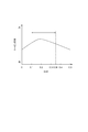
- the concave portion has a blade height of the variable nozzle vane as a cross section orthogonal to the camber direction. It includes a cross section where the ratio D / H of the depth D of the recess to H satisfies 0.1 ⁇ D / H ⁇ 0.2.
- variable nozzle vane described in (10) above, the action of forming a circulating flow in the gap can be strengthened, and the flow rate of the clearance flow can be effectively reduced. Thereby, turbine efficiency can be improved effectively.
- the concave portion has a cross section perpendicular to the camber direction, and the width relative to the width W of the concave portion. It includes a cross section where the ratio D / W of the depth D of the recess satisfies 0.1 ⁇ D / W ⁇ 0.35.
- variable nozzle vane described in (11) above, the action of forming a circulating flow in the gap can be strengthened, and the flow rate of the clearance flow can be effectively reduced. Thereby, turbine efficiency can be improved effectively.
- the variable nozzle vane is a piece on one of the one side wall and the other side wall.
- the wall portion that cantilever-supports the variable nozzle vane is referred to as a support wall portion
- the wall portion that does not cantilever the variable nozzle vane is referred to as a non-support wall portion
- the end surface facing the support wall portion is referred to as a support wall side end surface
- the end surface facing the non-support wall portion is referred to as a non-support wall side end surface.
- the clearance flow passing through the gap from the pressure surface side to the suction surface side is effectively spread over a wide range along the camber line. Can be suppressed.
- the end of the variable nozzle vane on the non-supporting wall portion side has a blade thickness that increases toward the non-supporting wall portion side.
- the taper part formed in this way is included.
- variable nozzle vane described in (13) above, by providing the tapered portion as compared with the case where the variable nozzle vane is not provided with the tapered portion, the non-supporting wall side end surface and the wall surface of the non-supporting wall portion are provided.
- the flow path length of the gap can be increased. For this reason, the pressure gradient between the pressure surface side and the suction surface side in the gap is reduced, and the flow rate of the clearance flow can be reduced.
- the suction surface of the tapered portion is arranged in the blade height direction so that the blade thickness increases as it approaches the non-supporting wall portion side. It includes a tapered surface that is inclined with respect to it.
- variable nozzle vane described in (14) above, the flow from the nozzle throat portion is less likely to be attracted to the wall surface of the non-supporting wall portion by the tapered surface of the suction surface of the tapered portion. For this reason, compared with the case where a taper part is not provided, the loss resulting from mixing (collision) with the flow from the said throat part and the clearance flow which flows through the said clearance gap can be reduced.
- the pressure surface of the tapered portion is formed in parallel to the blade height direction.
- variable nozzle vane described in (15) above, it is possible to reduce a loss due to mixing of the flow from the throat portion and the clearance flow while suppressing a decrease in the aerodynamic performance of the variable nozzle vane.
- the pressure surface of the tapered portion may be configured such that the blade thickness increases as it approaches the non-supporting wall portion side.
- a tapered surface inclined with respect to the height direction is included.
- the flow of the gap between the end surface on the non-supporting wall side and the wall surface of the non-supporting wall portion is compared with the case where the taper surface is not provided on the pressure surface of the taper portion.
- the road length can be increased. For this reason, the pressure gradient between the pressure surface side and the suction surface side in the gap is reduced, and the flow rate of the clearance flow can be reduced.
- the tapered portion is provided on the non-supporting wall side from the position of 80% of the blade height H in the nozzle vane. It is done.
- the ratio T2 of the maximum blade thickness T2 of the non-support wall side end surface to the maximum blade thickness T1 of the support wall side end surface / T1 satisfies 1.5 ⁇ T2 / T1 ⁇ 2.5.
- the flow path length of the gap between the end surface on the non-supporting wall side and the wall surface of the non-supporting wall portion is significantly increased as compared with the case where the tapered portion is not provided. For this reason, the pressure gradient between the pressure surface side and the suction surface side in the gap is reduced, and the flow rate of the clearance flow can be effectively reduced.
- variable nozzle vane in the variable nozzle vane described in (1) to (18) above, is a variable nozzle vane of a variable displacement turbocharger for an automobile.
- variable nozzle vane described in (19) above, the clearance flow of the variable nozzle vane in the variable displacement turbocharger for automobiles can be effectively suppressed.
- a variable capacity turbocharger includes a turbine rotor, a scroll flow path forming portion that forms a scroll flow path on an outer peripheral side of the turbine rotor, and the turbine from the scroll flow path.
- An exhaust gas flow path forming unit that forms an exhaust gas flow path for guiding the exhaust gas to the rotor, and the variable nozzle vane described in any one of (1) to (19) above.
- variable capacity turbocharger described in (20) above, since the variable nozzle vane described in any one of (1) to (19) is provided, the clearance flow is effectively suppressed and high turbine efficiency is achieved. Can be realized.
- variable nozzle vane capable of effectively suppressing the clearance flow and a variable displacement turbocharger including the same are provided.
- variable nozzle vane 2 (2A) It is a schematic sectional drawing in alignment with the axis of rotation of variable capacity type turbocharger 100 concerning one embodiment of the present invention. It is a perspective view showing a schematic structure of variable nozzle vane 2 (2A) concerning one embodiment. It is a perspective view showing a schematic structure of variable nozzle vane 2 (2A) concerning one embodiment. It is a figure which shows the schematic cross section (cross section orthogonal to the camber direction along the camber line of the non-supporting wall side end surface 32) of the variable nozzle vane 2 (2A). It is the elements on larger scale of the schematic cross section (cross section orthogonal to the camber direction along the camber line of the non-supporting wall side end surface 32) of the variable nozzle vane 2 (2A).
- variable nozzle vane 2 (2A) It is the elements on larger scale of the schematic cross section (cross section orthogonal to the camber direction along the camber line of the non-supporting wall side end surface 32) of the variable nozzle vane 2 (2A). It is a figure which shows the relationship between ratio D / W of the depth D of the recessed part 34 with respect to the width W of the recessed part 34, and turbine efficiency. It is the perspective view which looked at the variable nozzle vane 2 (2A) in FIG. 2 from the other direction. It is a figure which shows the relationship between the flow FD from the throat part in the variable nozzle vane in which the taper part is not provided, and the clearance flow FE.
- variable nozzle vane 2 2A
- clearance flow FE clearance flow FE
- FIG. 2B It is a perspective view showing a schematic structure of variable nozzle vane 2 (2B) concerning one embodiment. It is a figure which shows the schematic cross section of the variable nozzle vane 2 (2B). It is a figure which shows the schematic cross section of the variable nozzle vane 2 which concerns on other embodiment.
- an expression indicating that things such as “identical”, “equal”, and “homogeneous” are in an equal state not only represents an exactly equal state, but also has a tolerance or a difference that can provide the same function. It also represents the existing state.
- expressions representing shapes such as quadrangular shapes and cylindrical shapes represent not only geometrically strict shapes such as quadrangular shapes and cylindrical shapes, but also irregularities and chamfers as long as the same effects can be obtained. A shape including a part or the like is also expressed.
- the expressions “comprising”, “comprising”, “comprising”, “including”, or “having” one constituent element are not exclusive expressions for excluding the existence of the other constituent elements.
- FIG. 1 is a schematic cross-sectional view along the rotational axis of a variable capacity turbocharger 100 according to an embodiment of the present invention.
- the variable capacity turbocharger 100 is a turbocharger for automobiles, for example.
- variable capacity turbocharger 100 includes a turbine rotor 4, a scroll flow path forming portion 8 that forms a scroll flow path 6 on the outer peripheral side of the turbine rotor 4, and the scroll rotor 6 to the turbine rotor 4.
- the exhaust gas flow path forming part 12 for forming the exhaust gas flow path 10 for guiding the exhaust gas to the exhaust gas and the variable nozzle vane 2 provided in the exhaust gas flow path 10 are provided.
- the scroll flow path forming portion 8 is constituted by a turbine housing 14 that houses the turbine rotor 4.
- the exhaust gas flow path forming part 12 is provided in parallel with the support wall part 16 facing the support wall part 16 and supporting the variable nozzle vane 2 in a cantilever manner.
- the variable nozzle vane 2 is not supported in a cantilever manner.
- the support wall 16 is provided on the opposite side of the scroll flow path 6 (bearing housing 20 side) with respect to the variable nozzle vane 2 in the axial direction of the turbine rotor 4, and extends in the radial direction on the outer peripheral side of the turbine rotor 4.
- An annular plate (nozzle mount) is formed.
- the support wall portion 16 is formed with a through hole 22 penetrating in the thickness direction, and rotatably supports the shaft 24 of the variable nozzle vane 2 inserted through the through hole 22.
- the variable nozzle vane 2 is configured to rotate by transmitting a driving force from an actuator (not shown) to the shaft 24.
- the non-supporting wall portion 18 is provided on the scroll flow path 6 side (the side opposite to the bearing housing 20) with respect to the variable nozzle vane 2 in the axial direction of the turbine rotor 4, and extends radially along the outer peripheral side of the turbine rotor 4. It is comprised by the existing annular plate (nozzle plate).
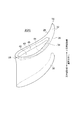
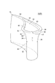
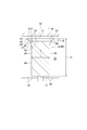
- FIG. 2 is a perspective view which shows schematic structure of the variable nozzle vane 2 (2A) which concerns on one Embodiment.
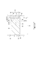
- FIG. 4 is a schematic cross-sectional view of the variable nozzle vane 2 (2A).
- variable nozzle vane 2 includes a pressure surface 26 (back surface), a suction surface 28 (abdominal surface), and a wall surface 17 (exhaust gas channel 10) of the support wall portion 16. And a non-supporting wall side end surface 32 facing the wall surface 19 of the non-supporting wall portion 18 (a wall surface facing the exhaust gas flow path 10). A recess 34 is formed in the end surface 32 on the non-supporting wall side.
- the dimension A1 of the recess 34 in the camber direction along the camber line CL of the non-supporting wall side end face 32 is larger than the dimension A2 of the recess 34 in the camber orthogonal direction orthogonal to the camber direction. For this reason, the clearance flow which passes the clearance gap C from the pressure surface 26 side to the negative pressure surface 28 side can be effectively suppressed over the wide range along the camber line CL.
- the recess 34 extends between the leading edge LE and the trailing edge TE so as not to reach each of the leading edge LE and the trailing edge TE.
- the interval d1 between the recess 34 and the rear edge TE is larger than the interval d2 between the recess 34 and the front edge LE.
- the above-described clearance flow can be suppressed without excessively reducing the wall thickness t on the trailing edge TE side of the variable nozzle vane 2. That is, it is possible to effectively improve the turbine efficiency while suppressing the occurrence of breakage in the portion on the trailing edge TE side of the variable nozzle vane 2.
- the recess 34 is connected to the front edge side portion 36 and the front edge side portion 36 in which the width W of the recess 34 in the camber orthogonal direction increases toward the rear edge TE side. And a trailing edge side portion 38 in which the width W of the concave portion 34 in the camber orthogonal direction decreases toward the edge side.
- the recess 34 has a bottom surface 42, a pressure surface side surface 44 provided on the pressure surface 26 side with respect to the camber line CL, and a camber line CL. And a suction surface side surface 46 provided on the suction surface 28 side.
- the pressure surface side surface 44 is curved along the pressure surface 26, and the suction surface side surface 46 is curved along the suction surface 28.
- the angle ⁇ p formed between the bottom surface 42 and the pressure surface side surface 44 is 90 degrees or less.
- the angle ⁇ p is 90 degrees, it is advantageous from the viewpoint of manufacturability, and if the angle ⁇ p is less than 90 degrees, it is advantageous from the viewpoint of forming the circulating flow FA in the vicinity of the pressure surface side surface 44. .
- the angle ⁇ s formed between the bottom surface 42 and the suction surface side surface 46 is 90 degrees or less.
- the angle ⁇ s is 90 degrees, it is advantageous from the viewpoint of manufacturability, and if the angle ⁇ s is less than 90 degrees, it is advantageous from the viewpoint of forming the circulating flow FC in the vicinity of the suction side surface 46. .
- the recess 34 has a cross section perpendicular to the camber direction, and the ratio D / W of the depth D of the recess 34 to the width W of the recess 34 is 0.1 ⁇ D / W. Includes a cross section that satisfies ⁇ 0.35.
- the recess 34 has a cross section orthogonal to the camber direction, and the ratio D / H of the depth D of the recess 34 to the blade height H of the variable nozzle vane 2 is 0.1 ⁇ . Includes a cross section that satisfies D / H ⁇ 0.2.
- the action of forming a circulating flow in the gap C can be strengthened, and the flow rate of the clearance flow can be effectively reduced. Thereby, turbine efficiency can be improved effectively.
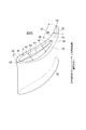
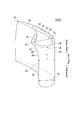
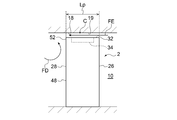
- FIG. 8 is a perspective view of the variable nozzle vane 2 (2A) in FIG. 2 viewed from the other direction.
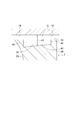
- the variable nozzle vane 2 (2A) includes a blade thickness constant portion 48 provided along the blade height direction (rotational axis direction of the variable nozzle vane 2), And a tapered portion 50 provided on the non-supporting wall portion 18 side with respect to the constant blade thickness portion.
- the tapered portion 50 is provided at the end portion 52 on the non-supporting wall portion 18 side of the variable nozzle vane 2 (2A), and is formed such that the blade thickness T increases as it approaches the non-supporting wall portion 18 side.
- the end surface 32 on the non-supporting wall side is provided by providing the tapered portion 50 as compared with the case where the tapered portion 50 is not provided on the variable nozzle vane (see FIG. 9).
- the flow path length Lp of the gap C between the non-supporting wall portion 18 can be increased. For this reason, the pressure gradient between the pressure surface 26 side and the negative pressure surface 28 side in the gap C is reduced, and the flow rate of the clearance flow can be reduced.
- the taper part 50 is provided in the non-supporting wall part 18 side from the position P1 of 80% of blade height H among the variable nozzle vanes 2 (2A).
- the aerodynamic performance of the variable nozzle vane is greatly deteriorated. Therefore, by providing the tapered portion 50 in the above range, the decrease in the aerodynamic performance is suppressed and the clearance flow is reduced. The flow rate can be reduced.
- the suction surface 28 of the tapered portion 50 is inclined with respect to the blade height direction so that the blade thickness T increases as it approaches the non-supporting wall portion 18 side.
- a tapered surface 54 is included.
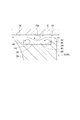
- the flow FD from the nozzle throat portion flows to the wall surface 19 of the non-supporting wall portion 18 by the tapered surface 54 of the suction surface 28 of the tapered portion 50. It becomes difficult to be attracted. For this reason, compared with the case where the taper part 50 is not provided (refer FIG. 9), the loss resulting from mixing (collision) with the said flow FD and the clearance flow FE which flows through the said clearance gap C can be reduced. .
- the pressure surface 26 of the tapered portion 50 is formed in parallel to the blade height direction from the support wall side end surface 30 to the non-support wall side end surface 32. .
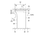
- FIG. 11 is a perspective view illustrating a schematic configuration of the variable nozzle vane 2 (2B) according to the embodiment.
- FIG. 4 is a schematic cross-sectional view of the variable nozzle vane 2 (2B).
- the pressure surface 26 of the tapered portion 50 is inclined with respect to the blade height direction so that the blade thickness T increases as it approaches the non-supporting wall portion 18 side.
- a tapered surface 56 is included.
- the present invention is not limited to the above-described embodiments, and includes forms obtained by modifying the above-described embodiments and forms obtained by appropriately combining these forms.
- the bottom surface 42 of the recess 34 may have a downward slope from the pressure surface side surface 44 toward the suction surface side surface 46. That is, the bottom surface 42 of the recess 34 may be inclined such that the distance d3 between the non-supporting wall portion 18 and the wall surface 19 increases from the pressure surface side surface 44 toward the suction surface side surface 46.
- the configuration in which the recess 34 is provided in the non-supporting wall side end surface 32 is illustrated. It only has to be done. However, in the form in which the variable nozzle vane 2 is cantilevered by the support wall portion 16, the clearance flow of the gap C between the wall surface 19 of the non-support wall portion 18 and the non-support wall side end surface 32 of the variable nozzle vane 2 is likely to be a problem. Therefore, it is desirable to provide the above-described recess 34 in the end surface 32 on the non-supporting wall side.
- variable nozzle vane 2 is cantilevered on the support wall 16 of the exhaust gas flow path forming unit 12.
- the variable nozzle vane is supported at both ends of the exhaust gas flow path forming unit. It may be supported. Even in this case, a recess is formed on at least one end face of the variable nozzle vane, and the dimension of the recess in the camber direction along the camber line is made larger than the dimension of the recess in the camber orthogonal direction perpendicular to the camber direction, Clearance flow can be effectively suppressed.
Landscapes
- Engineering & Computer Science (AREA)
- Mechanical Engineering (AREA)
- General Engineering & Computer Science (AREA)
- Chemical & Material Sciences (AREA)
- Combustion & Propulsion (AREA)
- Supercharger (AREA)
- Control Of Turbines (AREA)
- Turbine Rotor Nozzle Sealing (AREA)
Applications Claiming Priority (2)
| Application Number | Priority Date | Filing Date | Title |
|---|---|---|---|
| JP2016-123223 | 2016-06-22 | ||
| JP2016123223A JP6820161B2 (ja) | 2016-06-22 | 2016-06-22 | 可変ノズルベーン及び可変容量型ターボチャージャ |
Publications (1)
| Publication Number | Publication Date |
|---|---|
| WO2017221839A1 true WO2017221839A1 (ja) | 2017-12-28 |
Family
ID=60784791
Family Applications (1)
| Application Number | Title | Priority Date | Filing Date |
|---|---|---|---|
| PCT/JP2017/022371 Ceased WO2017221839A1 (ja) | 2016-06-22 | 2017-06-16 | 可変ノズルベーン及び可変容量型ターボチャージャ |
Country Status (2)
| Country | Link |
|---|---|
| JP (1) | JP6820161B2 (enExample) |
| WO (1) | WO2017221839A1 (enExample) |
Cited By (2)
| Publication number | Priority date | Publication date | Assignee | Title |
|---|---|---|---|---|
| WO2020011837A1 (de) * | 2018-07-12 | 2020-01-16 | Vitesco Technologies GmbH | Leitschaufel und mit einer solchen versehene turbinenanordnung |
| CN118224120A (zh) * | 2024-01-15 | 2024-06-21 | 中水珠江规划勘测设计有限公司 | 一种抑制叶顶泄漏涡的圆弧型凹槽叶顶及具有其的叶片泵 |
Families Citing this family (2)
| Publication number | Priority date | Publication date | Assignee | Title |
|---|---|---|---|---|
| JP7196819B2 (ja) * | 2019-11-06 | 2022-12-27 | 株式会社豊田自動織機 | ノズルベーン |
| JP2021105370A (ja) * | 2019-12-26 | 2021-07-26 | トヨタ自動車株式会社 | 過給機 |
Citations (8)
| Publication number | Priority date | Publication date | Assignee | Title |
|---|---|---|---|---|
| US20050226718A1 (en) * | 2004-04-12 | 2005-10-13 | Richard Marcis | Variable turbine geometry turbocharger |
| JP2007321721A (ja) * | 2006-06-05 | 2007-12-13 | Toshiba Corp | 軸流タービン段落および軸流タービン |
| JP2010112223A (ja) * | 2008-11-05 | 2010-05-20 | Ihi Corp | ターボチャージャ |
| KR20120048439A (ko) * | 2010-11-05 | 2012-05-15 | 한국항공대학교산학협력단 | 스퀄러팁을 갖는 가스터빈 블레이드 |
| WO2013026653A1 (de) * | 2011-08-18 | 2013-02-28 | Bosch Mahle Turbo Systems Gmbh & Co. Kg | Variable turbinen-/verdichtergeometrie |
| WO2014102962A1 (ja) * | 2012-12-27 | 2014-07-03 | 三菱重工業株式会社 | 可変容量型排気ターボ過給機 |
| US20140286750A1 (en) * | 2011-05-13 | 2014-09-25 | Bosch Mahle Turbo Systems Gmbh & Co. Kg | Variable turbine/compressor geometry |
| US20150152741A1 (en) * | 2012-01-13 | 2015-06-04 | Borgwarner Inc. | Turbocharger with variable turbine geometry having grooved guide vanes |
-
2016
- 2016-06-22 JP JP2016123223A patent/JP6820161B2/ja active Active
-
2017
- 2017-06-16 WO PCT/JP2017/022371 patent/WO2017221839A1/ja not_active Ceased
Patent Citations (8)
| Publication number | Priority date | Publication date | Assignee | Title |
|---|---|---|---|---|
| US20050226718A1 (en) * | 2004-04-12 | 2005-10-13 | Richard Marcis | Variable turbine geometry turbocharger |
| JP2007321721A (ja) * | 2006-06-05 | 2007-12-13 | Toshiba Corp | 軸流タービン段落および軸流タービン |
| JP2010112223A (ja) * | 2008-11-05 | 2010-05-20 | Ihi Corp | ターボチャージャ |
| KR20120048439A (ko) * | 2010-11-05 | 2012-05-15 | 한국항공대학교산학협력단 | 스퀄러팁을 갖는 가스터빈 블레이드 |
| US20140286750A1 (en) * | 2011-05-13 | 2014-09-25 | Bosch Mahle Turbo Systems Gmbh & Co. Kg | Variable turbine/compressor geometry |
| WO2013026653A1 (de) * | 2011-08-18 | 2013-02-28 | Bosch Mahle Turbo Systems Gmbh & Co. Kg | Variable turbinen-/verdichtergeometrie |
| US20150152741A1 (en) * | 2012-01-13 | 2015-06-04 | Borgwarner Inc. | Turbocharger with variable turbine geometry having grooved guide vanes |
| WO2014102962A1 (ja) * | 2012-12-27 | 2014-07-03 | 三菱重工業株式会社 | 可変容量型排気ターボ過給機 |
Cited By (5)
| Publication number | Priority date | Publication date | Assignee | Title |
|---|---|---|---|---|
| WO2020011837A1 (de) * | 2018-07-12 | 2020-01-16 | Vitesco Technologies GmbH | Leitschaufel und mit einer solchen versehene turbinenanordnung |
| CN112368467A (zh) * | 2018-07-12 | 2021-02-12 | 纬湃科技有限责任公司 | 导向叶片和设置有该导向叶片的涡轮机组件 |
| CN112368467B (zh) * | 2018-07-12 | 2024-01-30 | 纬湃科技有限责任公司 | 导向叶片和设置有该导向叶片的涡轮机组件 |
| CN118224120A (zh) * | 2024-01-15 | 2024-06-21 | 中水珠江规划勘测设计有限公司 | 一种抑制叶顶泄漏涡的圆弧型凹槽叶顶及具有其的叶片泵 |
| CN118224120B (zh) * | 2024-01-15 | 2025-10-24 | 中水珠江规划勘测设计有限公司 | 一种抑制叶顶泄漏涡的圆弧型凹槽叶顶及具有其的叶片泵 |
Also Published As
| Publication number | Publication date |
|---|---|
| JP2017227159A (ja) | 2017-12-28 |
| JP6820161B2 (ja) | 2021-01-27 |
Similar Documents
| Publication | Publication Date | Title |
|---|---|---|
| CN102365464B (zh) | 叶轮和旋转机械 | |
| JP6309651B2 (ja) | ターボ機械 | |
| US8251649B2 (en) | Blade row of axial flow type compressor | |
| WO2017221839A1 (ja) | 可変ノズルベーン及び可変容量型ターボチャージャ | |
| CN106715838B (zh) | 膨胀涡轮及涡轮增压器 | |
| US10837297B2 (en) | Centrifugal compressor and turbocharger | |
| JP6234600B2 (ja) | タービン | |
| JP5651459B2 (ja) | タービンエンジンにおける圧縮機の動作に関するシステム及び装置 | |
| WO2018147128A1 (ja) | 遠心圧縮機、ターボチャージャ | |
| CN104870775B (zh) | 可变容量型排气涡轮增压器 | |
| JP2021032106A (ja) | ベーンドディフューザ及び遠心圧縮機 | |
| US12460562B2 (en) | Mixed flow turbine and turbocharger | |
| JP6633761B2 (ja) | タービン及びターボチャージャ | |
| JP6959992B2 (ja) | タービン及びターボチャージャ | |
| WO2018116394A1 (ja) | ターボチャージャ及びターボチャージャのノズルベーン並びにタービン | |
| CN109312658B (zh) | 可变容量型涡轮增压器 | |
| CN111448374B (zh) | 涡轮及涡轮增压器 | |
| JP2024071544A (ja) | 遠心圧縮機のインペラ及び遠心圧縮機 | |
| WO2018146752A1 (ja) | 圧縮機及びターボチャージャ | |
| JP7165804B2 (ja) | ノズルベーン | |
| JP7755460B2 (ja) | ベーンドディフューザおよび遠心圧縮機 | |
| JPWO2018116395A1 (ja) | ターボチャージャ及びターボチャージャのノズルベーン並びにタービン | |
| JP6759463B2 (ja) | ターボチャージャ用タービン及びターボチャージャ | |
| JP2023023914A (ja) | 遠心圧縮機 | |
| JP2021124046A (ja) | 遠心圧縮機のディフューザ構造及び遠心圧縮機 |
Legal Events
| Date | Code | Title | Description |
|---|---|---|---|
| 121 | Ep: the epo has been informed by wipo that ep was designated in this application |
Ref document number: 17815307 Country of ref document: EP Kind code of ref document: A1 |
|
| NENP | Non-entry into the national phase |
Ref country code: DE |
|
| 122 | Ep: pct application non-entry in european phase |
Ref document number: 17815307 Country of ref document: EP Kind code of ref document: A1 |