WO2017221603A1 - 覚醒維持装置 - Google Patents
覚醒維持装置 Download PDFInfo
- Publication number
- WO2017221603A1 WO2017221603A1 PCT/JP2017/018957 JP2017018957W WO2017221603A1 WO 2017221603 A1 WO2017221603 A1 WO 2017221603A1 JP 2017018957 W JP2017018957 W JP 2017018957W WO 2017221603 A1 WO2017221603 A1 WO 2017221603A1
- Authority
- WO
- WIPO (PCT)
- Prior art keywords
- fluctuation
- intensity
- controller
- stimulus
- stimulation
- Prior art date
- Legal status (The legal status is an assumption and is not a legal conclusion. Google has not performed a legal analysis and makes no representation as to the accuracy of the status listed.)
- Ceased
Links
Images








Classifications
-
- B—PERFORMING OPERATIONS; TRANSPORTING
- B60—VEHICLES IN GENERAL
- B60K—ARRANGEMENT OR MOUNTING OF PROPULSION UNITS OR OF TRANSMISSIONS IN VEHICLES; ARRANGEMENT OR MOUNTING OF PLURAL DIVERSE PRIME-MOVERS IN VEHICLES; AUXILIARY DRIVES FOR VEHICLES; INSTRUMENTATION OR DASHBOARDS FOR VEHICLES; ARRANGEMENTS IN CONNECTION WITH COOLING, AIR INTAKE, GAS EXHAUST OR FUEL SUPPLY OF PROPULSION UNITS IN VEHICLES
- B60K28/00—Safety devices for propulsion-unit control, specially adapted for, or arranged in, vehicles, e.g. preventing fuel supply or ignition in the event of potentially dangerous conditions
- B60K28/02—Safety devices for propulsion-unit control, specially adapted for, or arranged in, vehicles, e.g. preventing fuel supply or ignition in the event of potentially dangerous conditions responsive to conditions relating to the driver
- B60K28/06—Safety devices for propulsion-unit control, specially adapted for, or arranged in, vehicles, e.g. preventing fuel supply or ignition in the event of potentially dangerous conditions responsive to conditions relating to the driver responsive to incapacity of driver
-
- B—PERFORMING OPERATIONS; TRANSPORTING
- B60—VEHICLES IN GENERAL
- B60W—CONJOINT CONTROL OF VEHICLE SUB-UNITS OF DIFFERENT TYPE OR DIFFERENT FUNCTION; CONTROL SYSTEMS SPECIALLY ADAPTED FOR HYBRID VEHICLES; ROAD VEHICLE DRIVE CONTROL SYSTEMS FOR PURPOSES NOT RELATED TO THE CONTROL OF A PARTICULAR SUB-UNIT
- B60W50/00—Details of control systems for road vehicle drive control not related to the control of a particular sub-unit, e.g. process diagnostic or vehicle driver interfaces
- B60W50/08—Interaction between the driver and the control system
- B60W50/14—Means for informing the driver, warning the driver or prompting a driver intervention
-
- G—PHYSICS
- G08—SIGNALLING
- G08B—SIGNALLING SYSTEMS, e.g. PERSONAL CALLING SYSTEMS; ORDER TELEGRAPHS; ALARM SYSTEMS
- G08B21/00—Alarms responsive to a single specified undesired or abnormal condition and not otherwise provided for
- G08B21/02—Alarms for ensuring the safety of persons
- G08B21/06—Alarms for ensuring the safety of persons indicating a condition of sleep, e.g. anti-dozing alarms
-
- G—PHYSICS
- G08—SIGNALLING
- G08G—TRAFFIC CONTROL SYSTEMS
- G08G1/00—Traffic control systems for road vehicles
- G08G1/16—Anti-collision systems
Definitions
- the present disclosure relates to a wakefulness maintaining device for maintaining a driver's wakefulness.
- Patent Document 1 discloses a technique for generating a fragrance as a second stimulus after a warning sound is emitted with a buzzer as a first stimulus when a driver's drowsiness is detected.
- Patent Document 1 In the technology disclosed in Patent Document 1, an attempt is made to continue the driver's awakening effect for a long time by generating a fragrance behind the warning sound. However, since the driver becomes accustomed while repeating such a stimulus many times, there is a possibility that the driver's awakening effect cannot be continued for a long time.
- the present disclosure has been made based on this situation, and an object of the present disclosure is to provide a wakefulness maintaining device that enables a driver's wakefulness effect to be continued for a longer time.
- a wakefulness maintaining device includes a trigger detection circuit that detects a predetermined trigger, and a wakefulness state of a subject when a trigger is detected by the trigger detection circuit.
- a plurality of stimulation devices that generate different types of stimuli for maintaining the stimulation, and a stimulation control circuit that generates those stimulations, and the stimulation control circuit sequentially determines the intensity of the stimulation generated from each of the plurality of stimulation devices.
- a rotation controller that changes the intensity of the stimulus so as to be stronger.
- a trigger when a trigger is detected, a plurality of types of stimuli for maintaining the awake state of the subject are generated, so that the driver is less likely to get used to the stimulus than when a single stimulus is generated.
- the intensity of a plurality of types of stimuli is changed so that the intensity of each of the stimuli generated from the plurality of stimulators increases in order, it is difficult to get used to each stimulus and it is very difficult to get used to the stimulus. As a result, the driver's awakening effect can be continued for a longer time.
- the wakefulness maintaining device includes a trigger detection circuit that detects a predetermined trigger, and a target person when a trigger is detected by the trigger detection circuit.
- a plurality of stimulation devices that generate different types of stimuli for maintaining the state of arousal, and a stimulation control circuit that generates the stimulations.
- a fluctuation controller is provided for changing the intensity of the stimulus so that fluctuation occurs in each intensity.
- a trigger when a trigger is detected, a plurality of types of stimuli for maintaining the awake state of the subject are generated, so that the driver is less likely to get used to the stimulus than when a single stimulus is generated.
- the intensity of each type of stimulus is changed so that the intensity of each of the stimuli generated from the plurality of stimulation devices fluctuates, it is difficult for the user to become accustomed to each stimulus due to this fluctuation. Hateful. As a result, the driver's awakening effect can be continued for a longer time.
- a driving assistance system 1 shown in FIG. 1 is used in an automobile (hereinafter simply referred to as a vehicle), and includes an ADAS (Advanced Driver Assistance Systems) locator 2, a peripheral monitoring sensor 3, an HMI (Human Machine Interface) system 4, and an air conditioning system. 5, vehicle control ECU6 and driving assistance ECU7 are included. Assume that the ADAS locator 2, the periphery monitoring sensor 3, the HMI system 4, the air conditioning system 5, the vehicle control ECU 6, and the driving support ECU 7 are connected to the in-vehicle LAN 8, for example.
- the vehicle equipped with the driving support system 1 is referred to as a host vehicle.
- the ADAS locator 2 includes a GNSS (Global Navigation Satellite System) receiver, an inertial sensor, and a map database (hereinafter referred to as DB) storing map data.
- the GNSS receiver receives positioning signals from a plurality of artificial satellites.
- the inertial sensor includes, for example, a triaxial gyro sensor and a triaxial acceleration sensor.
- the map DB is a non-volatile memory and stores map data such as link data, node data, and road shapes.
- the ADAS locator 2 sequentially measures the vehicle position of the host vehicle equipped with the ADAS locator 2 by combining the positioning signal received by the GNSS receiver and the measurement result of the inertial sensor.
- the vehicle position may be measured by using a travel distance obtained from a pulse signal sequentially output from a wheel speed sensor mounted on the host vehicle. And the measured vehicle position is output to in-vehicle LAN8.
- the ADAS locator 2 also reads map data from the map DB and outputs it to the in-vehicle LAN 8.
- the map data may be obtained from a server outside the vehicle using a vehicle-mounted communication module used for telematics communication such as DCM (Data Communication Module) mounted on the vehicle.
- DCM Data Communication Module
- the peripheral monitoring sensor 3 detects obstacles around the vehicle such as pedestrians, animals other than humans, moving objects such as bicycles, motorcycles, and other vehicles, and falling objects on the road, guardrails, curbs, and stationary objects such as trees. To detect. In addition, road markings such as travel lane lines and stop lines around the vehicle are detected.
- the peripheral monitoring sensor 3 is, for example, a peripheral monitoring camera that captures a predetermined range around the host vehicle, a millimeter wave radar that transmits an exploration wave to the predetermined range around the host vehicle, sonar, LIDAR (Light Detection and Ranging / Laser Imaging Detection and Ranging). The peripheral monitoring camera sequentially outputs captured images that are sequentially captured to the driving support ECU 7 as sensing information.
- a sensor that transmits an exploration wave such as sonar, millimeter wave radar, or LIDAR sequentially outputs a scanning result based on a received signal obtained when a reflected wave reflected by an obstacle is received to the driving support ECU 7 as sensing information.
- Information is used not only as countable nouns but also as countable nouns.
- Information is equivalent to an information item, and a plurality of information is equivalent to a plurality of information items.
- the HMI system 4 includes an HCU (Human Machine Interface Control Unit) 40, a DSM (Driver Status Monitor) 41, a display device 42, an audio output device 43, a vibrator 44, and an operation device 45.
- the HMI system 4 receives an input operation from the driver, presents information to the driver, and monitors the state of the driver. This driver is also referred to as the subject.
- the DSM 41 includes a near-infrared light source and a near-infrared camera, and a control unit that controls them.
- the DSM 41 is disposed, for example, on the upper surface of the instrument panel in a posture in which the near-infrared camera faces the driver's seat side of the own vehicle.
- the DSM 41 photographs the head of the driver irradiated with near infrared light from a near infrared light source with a near infrared camera.
- the image captured by the near-infrared camera is analyzed by the control unit.
- the control unit detects, for example, the driver's face direction and / or line-of-sight direction from the captured image.
- the DSM 41 extracts the degree of opening of the driver's eyes and the like from the captured image, and detects the driver's arousal level (that is, sleepiness).
- the DSM 41 is also referred to as a detection device or a monitor device.
- the case where the DSM 41 detects the wakefulness by classifying into 6 levels of sleepiness of 1 to 6 will be described as an example.
- the sleepiness classified into six levels is, in descending order of arousal level, sleepiness “1” that seems to be completely sleepless (in other words, awake state), sleepiness “2” that seems to be a little sleepy, sleepiness that is likely to sleep “3” ”, Sleepiness“ 4 ”that seems to be quite sleepy, sleepiness“ 5 ”that seems to be very sleepy, and sleepiness“ 6 ”that is sleeping (in other words, a sleep state).
- the DSM 41 outputs the detected sleepiness to the in-vehicle LAN 8.
- Examples of the display device 42 include a combination meter, CID (Center Information Display), HUD (Head-Up Display), LED, and the like.
- This display device 42 is also referred to as a stimulator.
- the combination meter is arranged in front of the driver's seat.
- the CID is arranged above the center cluster in the passenger compartment.
- the combination meter displays various images for information presentation on the display screen of the liquid crystal display based on the image data acquired from the HCU 40.
- the HUD projects image light based on image data acquired from the HCU 40 onto a projection area defined by the windshield. The light of the image reflected on the vehicle interior side by the windshield is perceived by the driver sitting in the driver's seat.
- the driver can visually recognize the virtual image of the image projected by the HUD by superimposing it on the outside scene in front of the vehicle.
- the LED is disposed at a position that is noticeable to the driver, such as an instrument panel, and the light emission is controlled by the HCU 40.
- Examples of the sound output device 43 include an audio speaker that outputs sound and a buzzer that outputs sound. This audio output device 43 is also referred to as a stimulator.
- the vibrator 44 is provided at a location where the driver of the own vehicle comes into contact, such as a steering wheel or a seat of the driver's seat, and gives a stimulus to the driver by vibration. The vibration of the vibrator 44 is controlled by the HCU 40. This vibrator 44 is also referred to as a stimulator.
- the operation device 45 is also referred to as an operation switch 45, and is a switch group operated by the driver.
- the operation device 45 includes a steering switch provided in a spoke spoke portion of the own vehicle, a touch switch integrated with a display device 42 having a display, and the like.
- the operation device 45 includes a switch (hereinafter referred to as a stimulus request switch) for a driver to request generation of a stimulus for maintaining arousal (hereinafter referred to as an arousal stimulus).
- the stimulus request switch in the operation device 45 is also referred to as an operation input device or an operation input switch.
- the HCU 40 includes a CPU, a volatile memory, a non-volatile memory, an I / O, and a bus connecting them, and executes various processes by executing a control program stored in the non-volatile memory.
- This HCU 40 is also referred to as a wakefulness maintenance device. Details of the processing in the HCU 40 will be described later.
- the air conditioning system 5 is an air conditioning system for a vehicle that acquires air conditioning request information including air conditioning related setting values set by a passenger of the own vehicle from the HCU 40 and adjusts the temperature, cleanliness, airflow, and the like in the passenger compartment.
- the air conditioning system 5 includes an air conditioning control ECU 50, an air conditioner unit 51, and an aroma unit 52.
- the air conditioner unit 51 generates hot air and cold air that are supplied to the passenger compartment from an air outlet provided in an instrument panel or the like.
- the aroma unit 52 atomizes aroma oil such as essential oil containing a fragrance (aroma) component.
- a fragrance component a component having an arousal effect is used.
- the fragrance component atomized by the aroma unit 52 is mixed with the airflow generated by the air conditioner unit 51 and supplied to the passenger compartment.
- the air conditioner unit 51 and the aroma unit 52 are also referred to as a stimulator.
- the air conditioning control ECU 50 includes a CPU, a volatile memory, a nonvolatile memory, an I / O, and a bus for connecting them, and executes various processes by executing a control program stored in the nonvolatile memory.
- the air conditioning control ECU 50 is connected to the in-vehicle LAN 8 and receives the air conditioning request information output from the HCU 40 to the in-vehicle LAN 8.
- the air conditioning control ECU 50 is connected to the air conditioner unit 51 and the aroma unit 52, and controls the operation of the air conditioner unit 51 and the aroma unit 52 based on the acquired air conditioning request information.
- the vehicle control ECU 6 is an electronic control device that performs acceleration / deceleration control and / or steering control of the host vehicle.
- the vehicle control ECU 6 includes a steering ECU that performs steering control, a power unit control ECU that performs acceleration / deceleration control, a brake ECU, and the like.
- the vehicle control ECU 6 obtains detection signals output from sensors such as an accelerator position sensor, a brake pedal force sensor, a rudder angle sensor, and a wheel speed sensor mounted on the host vehicle, and performs electronic control throttle, brake actuator, EPS (Electric Power Steering) Outputs control signals to each travel control device such as a motor. Further, the vehicle control ECU 6 can output the detection signals of the above-described sensors to the in-vehicle LAN 8.
- the driving support ECU 7 includes a volatile memory, a non-volatile memory, an I / O, and a bus connecting them, and executes various processes by executing a control program stored in the non-volatile memory.
- the driving assistance ECU 7 recognizes the traveling environment of the host vehicle from the vehicle position and map data of the host vehicle acquired from the ADAS locator 2, the sensing information acquired from the surrounding monitoring sensor 3, and the like.
- the driving assistance ECU 7 generates a driving plan for driving the vehicle by automatic driving based on the recognized driving environment. For example, a recommended route for directing the vehicle to the destination is generated as a medium- to long-term travel plan. Also, a short-term travel plan for traveling according to the recommended route is generated.
- the driving support ECU 7 causes the vehicle control ECU 6 to automatically perform acceleration, braking, and / or steering according to the generated travel plan.
- the driving support ECU 7 can switch the level of automation of automatic driving (hereinafter referred to as the automation level).
- the automation levels include automation level 0 (No-Automation), automation level 1 (Function-specific Automation), and automation level 2 (Combined) according to the classification defined by NHTSA (National Highway Traffic Safety Safety Administration). There are five stages: Function (Automation), Automation level 3 (Limited Self-Driving Automation), and Automation level 4 (Full Self-Driving Automation).
- the automation level 0 is a stage where the driver operates all the main control systems such as the brake, steering, throttle, and driving force of the vehicle without performing automation. In other words, it is a stage where automatic driving is not carried out in which any of acceleration, braking, and steering is not automatically controlled. That is, it is a stage of manual operation.
- Automation level 1 is a stage in which a function that automates one of the main control systems of the host vehicle is executed independently. In other words, it is a stage of automating a specific function that automatically controls any one of acceleration, braking, and steering.
- the automation level 2 is a stage in which functions obtained by automating one of the main control systems of the host vehicle are executed in combination.
- the automation level 3 is a stage in which all of the main control system of the vehicle is automated, and the driver performs a driving operation only when the driver changes to a traffic situation to be driven. In other words, it is a semi-automatic operation stage in which acceleration, braking, and steering are all automatically controlled except in an emergency.
- the automation level 4 is a stage in which all of the main control system of the vehicle is automated, and the driver does not need to perform a driving operation at any time during traveling. In other words, even in an emergency, it is a fully automatic operation stage in which acceleration, braking, and steering are all automatically controlled.
- the automation level 1 to the automation level 4 can be said to be an automatic driving stage in which at least one of acceleration, braking, and steering is automatically controlled.
- Switching of the execution of the automatic driving in the driving support ECU 7 is autonomous depending on the end of the driving in the scheduled automatic driving section, the recognized driving environment, the sensing failure in the peripheral monitoring sensor 3, or the like. What is necessary is just to be the structure performed. In addition, it may be configured to be performed according to an input operation by the driver to the operation device 45. Further, the stage division when switching the automation level is not limited to the example described above. For example, it may be divided into stages such as a stage of manual driving, a stage where some driving operations are performed automatically, and a stage of fully automatic driving, or may be divided into other stages.
- the HCU 40 includes a trigger detection circuit 401 and a stimulus control circuit 402, and the stimulus control circuit 402 includes a rotation controller 403 and a fluctuation controller 408.
- the rotation controller 403 includes an order controller 404, a steepness controller 405, a change cycle controller 406, and an intensity difference controller 407.
- the fluctuation controller 408 includes a fluctuation cycle controller 409 and a fluctuation width controller 410. Note that part or all of the functions executed by the HCU 40 may be configured by hardware using one or a plurality of ICs.
- the controller is also referred to as a control unit.
- the trigger detection circuit 401 is also referred to as a trigger detector, and detects a trigger for generating an arousal stimulus. For example, when the drowsiness detected by the DSM 41 is greater than or equal to the threshold, the trigger detection circuit 401 detects this as a trigger.
- the threshold value referred to here is drowsiness to the extent that the driver needs to be awake when performing a driving operation by the driver, and may be drowsiness “3” as an example.
- the trigger detection circuit 401 detects this as a trigger.
- the stimulus request switch may be operated by the driver when the driver wants to generate an arousal stimulus at his / her own timing.
- the DSM41 does not detect a sleepiness exceeding the threshold value and the wakeful stimulus does not occur Etc.
- the trigger detection circuit 401 may be configured to detect, as a trigger, that the automation level of automatic driving is switched to a threshold value or less by monitoring the driving support ECU 7.
- the threshold value referred to here may be a level that corresponds to the boundary between automation levels at which the driver needs to wake up.
- the automation level 3 that is a boundary that requires monitoring by the driver, such as switching from the automation level 4 to the automation level 3 or lower, may be used as the threshold value.
- the automation level 2 that is a boundary where the driving operation by the driver is required, such as switching from the automation level 3 or higher to the automation level 2 or lower, may be used as the threshold value.
- the automation level 0 that is the boundary from the automatic operation to the manual operation, such as switching from the automation level 1 or higher (for example, the automation level 3 or 4) to the automation level 0, may be used as the threshold value.
- the trigger detection circuit 401 may be configured to detect that the automation level is switched to a threshold value or less when the automation level of the automatic driving is switched to a threshold value or less, and the automation level is a threshold value. It is good also as a structure which detects that it switches to the following as a trigger.
- a configuration that detects that the automation level is switched to a threshold value or less as a trigger it is predicted in advance from the travel plan generated by the driving support ECU 7 that the automation level is switched to a threshold value or less, and the automation level is set to a threshold value or less. What is necessary is just to detect a trigger before the timing which switches. How long before the timing when the automation level is switched below the threshold may be arbitrarily set. For example, it may be 4 seconds ago, or 100 meters ago.
- the stimulus control circuit 402 is also referred to as a stimulus electronic control unit.
- the trigger detection circuit 401 detects a trigger
- the stimulus control circuit 402 simultaneously generates a wake-up stimulus from a plurality of stimulus devices that generate the wake-up stimulus.
- the stimulation device include a display device 42, an audio output device 43, a vibrator 44, an air conditioner unit 51, and an aroma unit 52.
- the stimulus control circuit 402 controls the operation of the air conditioner unit 51 and the aroma unit 52 by outputting air conditioning request information to the air conditioning control ECU 50.
- the awakening stimulus generated from the display device 42 is, for example, LED light emission.
- the arousal stimulus generated from the audio output device 43 is an alarm sound.
- the awakening stimulus generated from the vibrator 44 is a vibration.
- the awakening stimulus generated from the air conditioner unit 51 is cold air.
- the arousal stimulus generated from the aroma unit 52 is a fragrance having an arousal effect.
- the stimulus control circuit 402 includes the rotation controller 403 and the fluctuation controller 408 as described above, and the intensity of the arousal stimulus is sequentially increased by the rotation controller 403 so that the intensity of the arousal stimulus generated from each of the plurality of stimulation devices increases in order. Is changed (that is, rotated). Further, the stimulus control circuit 402 causes the fluctuation controller 408 to change the intensity of the arousal stimulus so that fluctuation occurs in the intensity of each of the arousal stimuli respectively generated from the plurality of stimulation devices.
- the fluctuation here refers to a state in which the intensity of the arousal stimulus periodically fluctuates up and down around the reference intensity.
- the intensity of the light emission of the LED may be changed as an example.
- the volume of the alarm sound may be changed as an example.
- the configuration may be such that the intensity of vibration is changed as an example.
- the temperature or the air volume of the cold air may be changed.
- the configuration may be such that the concentration of fragrance is changed.
- the rotation controller 403 sequentially increases the intensity of a plurality of types of wakeful stimuli by rotation. That is, the generation mode of the awakening stimulus generated from each of the plurality of stimulation devices is sequentially changed.
- the rotation controller 403 when the intensity of a certain type of arousal stimulus is increased, the intensity of the other type of arousal stimulus is decreased.
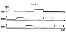
- FIG. 3 shows an example in which the intensity is increased in the order of the arousal stimulus A, the arousal stimulus B, and the arousal stimulus C.
- the rotation controller 403 uses the order controller 404, the steepness controller 405, the change period controller 406, and the intensity difference controller 407 to increase the timing of the awakening stimulus in each stimulation device, the magnitude of the intensity, and the time variation of the intensity. Control and switch rate (ie, steepness).
- the rotation controller 403 also changes the generation mode of the awakening stimulus generated from each of the plurality of stimulation devices by this switching.
- the order controller 404 controls the order of rotation for generating awakening stimuli from each stimulating device.
- the order controller 404 may be configured to control the order of rotation in accordance with a default setting value for the order of rotation stored in advance in the nonvolatile memory of the HCU 40.
- the order controller 404 when satisfying a predetermined condition, changes this order when the intensity of the arousal stimulus generated from each of the plurality of stimulating devices is increased in order by rotation as shown in FIG. Switch.
- a predetermined condition An example of the predetermined condition will be described later.
- FIG. 4 shows an example in which the rotation in the order of the arousal stimulus A, the arousal stimulus B, and the arousal stimulus C is switched to the order of the arousal stimulus C, the arousal stimulus B, and the arousal stimulus A.
- the order controller 404 may be configured to randomly switch the rotation order, or may be configured to switch in the reverse order of the default setting value.
- the steepness controller 405 controls the steepness of the intensity change when the intensity of the arousal stimulus generated from each stimulating device is strongly changed by rotation.
- the steepness controller 405 may be configured to control the rotation order according to the default setting value of the time change rate when the intensity of the wakefulness stimulus stored in advance in the nonvolatile memory of the HCU 40 is changed. .
- the steepness controller 405 switches the steepness of the intensity change of the awakening stimulus generated from each of the plurality of stimulation devices as shown in FIG.
- FIG. 5 shows an example in which switching is performed so that the steepness of the intensity change of the arousal stimulus is increased.
- the switching of the steepness of the intensity change may be configured so as to increase the steepness, may be configured so as to decrease the steepness, or may be configured to switch the steepness randomly.
- the change cycle controller 406 controls a change cycle (hereinafter referred to as a change cycle) when the intensity of the arousal stimulus generated from each stimulation device is strongly changed by rotation.
- a change cycle a change cycle
- the change cycle controller 406 may be configured to control the change cycle according to the default setting value of the change cycle stored in advance in the nonvolatile memory of the HCU 40.
- the change cycle controller 406 switches the change cycle of the arousal stimulus generated from each of the plurality of stimulation devices as shown in FIG.
- FIG. 6 shows an example in the case of switching so that the change cycle Pc2 after switching is shorter than the change cycle Pc1 before switching.
- the change period may be switched so that the change period becomes shorter, may be changed so that the change period becomes longer, or may be changed randomly.
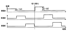
- the intensity difference controller 407 controls an intensity difference between the upper limit and the lower limit of each arousal stimulus (hereinafter, changed intensity difference) when the intensity of the arousal stimulus generated from each stimulation device is strongly changed by rotation.
- the change intensity difference can be rephrased as an intensity difference between when the intensity is increased and when the intensity is decreased when the intensity of the arousal stimulus is changed into two patterns of strength and weakness by rotation.
- the intensity difference controller 407 may be configured to control the change intensity difference according to a default setting value of the change intensity difference stored in advance in the nonvolatile memory of the HCU 40.
- the intensity difference controller 407 switches the change intensity difference of the awakening stimulus generated from each of the plurality of stimulation devices as shown in FIG. An example of the predetermined condition will be described later.
- FIG. 7 shows an example in which switching is performed such that the change intensity difference Id2 after switching is larger than the change intensity difference Id1 before switching.
- the change intensity difference may be switched so that the change intensity difference becomes large, may be changed so that the change intensity difference becomes small, or may be changed randomly.
- strength and it is good also as a structure which switches a change intensity difference by changing only the minimum intensity
- the steepness controller 405, the change cycle controller 406, and the intensity difference controller 407 may have different values for each type of arousal stimulus for the steepness, change cycle, and change intensity difference.
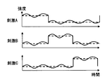
- the fluctuation controller 408 changes the intensity of the arousal stimulus so that fluctuation occurs in the intensity of each of the arousal stimuli generated from the plurality of stimulation devices. That is, the generation mode of the awakening stimulus generated from each of the plurality of stimulation devices is sequentially changed.
- this criterion is the center. An example in which the intensity is periodically changed up and down is shown.
- the fluctuation cycle controller 409 controls the fluctuation period (hereinafter referred to as fluctuation period) when changing the intensity of the arousal stimulus so that fluctuation occurs in each intensity of the arousal stimulus generated from each stimulation device.
- the fluctuation cycle controller 409 may be configured to control the fluctuation period according to the default setting value of the fluctuation period stored in advance in the nonvolatile memory of the HCU 40.
- the fluctuation cycle controller 409 switches the fluctuation period of the awakening stimulus generated from each stimulation device as shown in FIG. An example of the predetermined condition will be described later.
- FIG. 9 shows an example in which switching is performed such that the fluctuation period Pc4 after switching is shorter than the fluctuation period Pc3 before switching.
- the switching of the fluctuation cycle may be configured so as to shorten the fluctuation period, may be configured so as to increase the fluctuation period, or may be configured to switch the fluctuation period randomly.
- the fluctuation cycle controller 409 compares the fluctuation cycle after switching with the change cycle (see Pc6 in FIG. 10) controlled by the change cycle controller 406. To do. If the fluctuation period is equal to or longer than the change period, the fluctuation period after switching is changed to a fluctuation period shorter than the change period. That is, when switching the fluctuation cycle, the fluctuation cycle controller 409 switches the fluctuation cycle so that the fluctuation cycle is shorter than the change cycle.
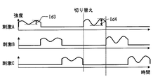
- the fluctuation width controller 410 controls the fluctuation width of the intensity of the arousal stimulus in this fluctuation when changing the intensity of the awakening stimulus so that fluctuation occurs in each intensity of the awakening stimulus generated from each stimulation device.
- the fluctuation width can be paraphrased as an intensity difference between the upper limit and the lower limit of the intensity of the arousal stimulus in the fluctuation.
- the fluctuation width controller 410 may be configured to control the fluctuation width in accordance with a default setting value of the fluctuation width stored in advance in the nonvolatile memory of the HCU 40.
- the fluctuation width controller 410 switches the fluctuation width of the awakening stimulus generated from each stimulation device as shown in FIG.
- FIG. 11 shows an example in which switching is performed such that the fluctuation width Id4 after switching is larger than the fluctuation width Id3 before switching.
- the switching of the fluctuation width may be configured so as to increase the fluctuation width, may be configured so as to decrease the fluctuation width, or may be configured to switch the fluctuation width randomly.
- the fluctuation width may be changed by changing only the upper limit of the fluctuation width, the fluctuation width may be changed by changing only the lower limit of the fluctuation width, and the upper and lower limits of the fluctuation width may be changed. It is good also as a structure which switches a fluctuation width by changing both.
- the fluctuation width controller 410 switches the fluctuation width (see Id5 in FIG. 12), the fluctuation width after switching and the changed intensity difference controlled by the intensity difference controller 407 (see Id6 in FIG. 12). Compare. If the fluctuation width is equal to or greater than the change intensity difference, the fluctuation width after switching is changed to a fluctuation width in which the difference between the upper limit and the lower limit of the intensity is smaller than the change intensity difference. That is, when switching the fluctuation width, the fluctuation width controller 410 switches the fluctuation width so that the fluctuation width becomes smaller than the change intensity difference.
- arousal stimulus related processing a flow of processing related to control for generating an arousal stimulus in the HCU 40 (hereinafter, arousal stimulus related processing) will be described using the flowchart of FIG. 13 may be configured such that, for example, when the ignition power of the host vehicle is turned on, the power of the HCU 40 is also turned on and started.
- the described flowchart includes a plurality of sections (or referred to as steps), and each section is expressed as, for example, S1. Further, each section can be divided into a plurality of subsections, while a plurality of sections can be combined into one section. Each section is also referred to as a device, module, unit, or unique name.
- the detection section can be referred to as a detection device, a detection module, a detector, or a detector.
- the section includes (i) not only a section of software combined with a hardware unit (eg, a computer) but also (ii) a section of hardware (eg, an integrated circuit, a wiring logic circuit) and related devices. It can be realized with or without the function.
- the hardware section can be included inside the microcomputer.
- the stimulus control circuit 402 simultaneously generates awakening stimuli from a plurality of stimulating devices.
- the rotation controller 403 rotates the intensity of the awakening stimulus generated from each stimulation device. That is, rotation is added to the arousal stimulus generated from each stimulator. Further, regarding the order of rotating the intensity of the arousal stimulus, the steepness of the intensity change, the change period, and the change intensity difference, the order controller 404, the abruptness controller 405, the change period controller 406, and the intensity difference according to the default setting values. It is controlled by the controller 407.
- the fluctuation controller 408 causes fluctuation in the intensity of each awakening stimulus generated from each stimulation apparatus. That is, the fluctuation is added to the awakening stimulus generated from each stimulating device. Further, the fluctuation cycle and fluctuation width at the time of causing fluctuation in the intensity of the arousal stimulus are controlled by the fluctuation period controller 409 and the fluctuation width controller 410 according to default setting values.
- the stimulus control circuit 402 Determines that the driver is drowsy (YES in S6), and proceeds to S7. That is, it is determined that the awakening effect is insufficient in the conventional awakening stimulation, and the process proceeds to S7.
- the trigger detection circuits 401 detects the trigger, it is determined that there is no driver drowsiness (NO in S6), and the arousal stimulus related processing is terminated. That is, the arousal stimulus related processing is terminated as if the driver has been awakened by the arousal stimulus.
- the order controller 404 switches the order in which the intensity of the arousal stimulus generated from each stimulating device is increased in order by rotation from the previous order.
- the change cycle controller 406 switches the change cycle of the awakening stimulus generated from each stimulation device from the change cycle so far. In order to enhance the awakening effect, it is preferable to switch so that the change period is shortened.
- the intensity difference controller 407 switches the change intensity difference of the awakening stimulus generated from each stimulation device from the change intensity difference so far. In order to enhance the awakening effect, it is preferable to switch so that the change intensity difference becomes large.
- the steepness controller 405 switches the steepness of the intensity change of the awakening stimulus generated from each stimulating device from the steepness so far. In order to enhance the awakening effect, it is preferable to switch so as to increase the steepness.
- the fluctuation width controller 410 switches the fluctuation width of the awakening stimulus generated from each stimulation device from the fluctuation width until then. In order to enhance the awakening effect, it is preferable to switch so that the fluctuation width becomes large.
- the fluctuation width controller 410 compares the fluctuation width after switching in S11 with the current change intensity difference controlled by the intensity difference controller 407. If the fluctuation width is less than the change intensity difference (YES in S12), the process proceeds to S14. On the other hand, if the fluctuation width is equal to or greater than the change intensity difference (NO in S12), the process proceeds to S13. In S13, the fluctuation width controller 410 changes the fluctuation width after switching in S11 to be smaller than the current change intensity difference while making the fluctuation width different from the fluctuation width before switching in S11.
- the fluctuation cycle controller 409 switches the fluctuation cycle of the awakening stimulus generated from each stimulation device from the fluctuation cycle so far. In order to enhance the awakening effect, it is preferable to switch so that the fluctuation cycle is shortened.
- the fluctuation cycle controller 409 compares the fluctuation cycle after switching in S14 with the current change cycle controlled by the change cycle controller 406. If the fluctuation cycle is less than the change cycle (YES in S15), the process proceeds to S17. On the other hand, when the fluctuation cycle is equal to or longer than the change cycle (NO in S15), the process proceeds to S16. In S16, the fluctuation cycle controller 409 changes the fluctuation period after switching in S14 to be shorter than the current change period while making the fluctuation period different from the fluctuation period before switching in S14.
- the stimulus control circuit 402 determines that the driver is drowsy in S ⁇ b> 6, the order of rotating the intensity of the wakeful stimulus, the sharpness of the intensity change, the change period, the change intensity difference,
- the present invention is not necessarily limited thereto.
- the stimulus control circuit 402 determines whether or not the driver is drowsy each time. It is good also as a structure which increases the kind of generation
- the processing of S12 and S13 in the flowchart of FIG. 13 may be omitted, or the processing of S15 and S16 may be omitted.
- the stimulus control circuit 402 determines that there is no driver drowsiness in S6 after switching the generation mode of the arousal stimulus, the setting value used for the control of the arousal stimulus at that time is changed to a new default value. It is good also as a structure which resets as a setting value.
- ⁇ Summary of Embodiment 1> since a plurality of types of arousal stimuli are generated at the same time, the driver is less likely to get used to the stimulation than when a single stimulus is generated. Moreover, since the intensity
- the switching of the order when rotating the intensity of the arousal stimulus is considered to be easily recognized by the driver, so that the driver is likely to feel uncomfortable, and it is considered that it is particularly difficult to get used to the arousal stimulus.
- habituation to the awakening stimulus is less likely to occur, so that the driver's awakening effect can be continued for a longer time.
- the trigger detection circuit 401 detects that the automatic operation automation level is switched to a threshold value or less. Therefore, even if the driver's arousal level is reduced due to the reduction of monitoring and driving operations during automatic driving, the awakening is required when the automation level is lowered and the driver's monitoring and driving operations are required. It becomes possible to make it.
- the configuration is not limited to the configuration shown in the first embodiment, and a configuration in which fluctuation is attenuated and amplified in accordance with a change in the intensity of the awakening stimulus in the rotation controller 403 (hereinafter, a second embodiment) may be employed.
- a second embodiment a configuration in which fluctuation is attenuated and amplified in accordance with a change in the intensity of the awakening stimulus in the rotation controller 403.
- the configuration of the second embodiment will be described.
- the driving support system 1 of the second embodiment is the same as the driving support system 1 of the first embodiment except that the stimulus control circuit 402 of the HCU 40 includes a fluctuation controller 408a instead of the fluctuation controller 408.
- the fluctuation controller 408a a schematic configuration of the fluctuation controller 408a will be described with reference to FIG.
- the fluctuation controller 408a includes a fluctuation cycle controller 409a and a fluctuation width controller 410a.
- the fluctuation cycle controller 409a and the fluctuation width controller 410a are the fluctuation period controller 409 and the fluctuation width controller 410 of the first embodiment, except that the fluctuation attenuation and amplification are performed in accordance with the change of the intensity of the awakening stimulus in the rotation controller 403. It is the same.
- a configuration related to attenuation and amplification of fluctuations in the fluctuation period controller 409a and fluctuation width controller 410a, which is different from the fluctuation period controller 409 and fluctuation width controller 410 of the first embodiment, will be described.
- the controller is also referred to as a control unit.
- the fluctuation period controller 409a includes a fluctuation period extender 4091 and a fluctuation period shortener 4092 as shown in FIG.
- the fluctuation cycle extender 4091 switches the fluctuation cycle longer than before the change.
- the fluctuation period shortener 4092 switches the fluctuation period to be shorter than that before the change when the rotation controller 403 changes the intensity of the arousal stimulus strongly.
- the fluctuation cycle controller 409a preferably switches the fluctuation period so that the fluctuation period is shorter than the change period controlled by the change period controller 406 when switching the fluctuation period.
- the fluctuation width controller 410 a includes a fluctuation width attenuator 4101 and a fluctuation width amplifier 4102.
- the fluctuation width attenuator 4101 switches the fluctuation width to be smaller than that before the change when the rotation controller 403 changes the intensity of the awakening stimulus to be weak.
- the fluctuation width amplifier 4102 switches the fluctuation width to be larger than that before the change when the rotation controller 403 changes the intensity of the awakening stimulus strongly.
- the fluctuation width controller 410 a preferably switches the fluctuation width so that the fluctuation width becomes smaller than the change intensity difference controlled by the intensity difference controller 407 when switching the fluctuation width.
- the fluctuation controller 408a may make it easier for the driver to recognize the change in the intensity of the arousal stimulus by stopping the fluctuation itself, as shown in FIG. 15, when the rotation controller 403 changes the intensity of the awakening stimulus to be weak. .
- the fluctuation controller 408a changes the intensity of the arousal stimulus to be weaker by the rotation controller 403, the intensity of the arousal stimulus is changed by switching the fluctuation cycle longer and changing the fluctuation width smaller as shown in FIG. The change may be easily recognized by the driver.
- the fluctuation controller 408a strongly changes the intensity of the wakeful stimulus by the rotation controller 403, as shown in FIG. 17, the intensity of the wakeful stimulus is changed by switching the fluctuation cycle shorter and changing the fluctuation width larger as shown in FIG. May be easily recognized by the driver.
- the flowchart of FIG. 18 may be configured to start when rotation is added to the arousal stimulus generated from each stimulating device in the arousal stimulus related processing of the HCU 40.
- the rotation emphasis related process may be configured to be performed for the rotation of the awakening stimulus in each stimulation device.
- the fluctuation cycle extender 4091 switches the fluctuation cycle longer than before the change of the intensity of the arousal stimulus for the stimulation device that weakens the intensity of the arousal stimulation.
- the fluctuation width attenuator 4101 switches the fluctuation width to be smaller than that before the change of the intensity of the arousal stimulus for the stimulation device that weakens the intensity of the arousal stimulation, and proceeds to S27.
- the fluctuation period shortener 4092 switches the fluctuation period shorter than before the change of the intensity of the arousal stimulus for the stimulation device that increases the intensity of the arousal stimulation.
- the fluctuation width amplifier 4102 switches the fluctuation width to be greater than that before the change of the intensity of the arousal stimulus for the stimulation device that increases the intensity of the arousal stimulation, and proceeds to S27.
- the driver in addition to the effect of the configuration of the first embodiment, it is possible to achieve an effect that the driver can more easily recognize the change in the intensity of the arousal stimulus while adding the fluctuation to the arousal stimulus. .
- the intensity of the wakeful stimulus changes, the wakefulness is attenuated by attenuating the fluctuation when it is weak, or by amplifying the fluctuation when it is strong. make it easier for the driver to recognize the rotation of the intensity of the stimulus. Therefore, it is possible to expect a high effect of both the prevention of habituation of two types of arousal stimuli such as rotation and fluctuation of arousal stimuli, and the driver's arousal level can be maintained high.
- switching the fluctuation width makes it easier for the driver to notice the change in the intensity of the arousal stimulus, so the configuration that switches the fluctuation width is better. More preferred.
- by stopping the fluctuation itself as the fluctuation attenuation it becomes easier for the driver to notice a change in the intensity of the arousal stimulus. Therefore, it is more preferable to stop the fluctuation itself as the fluctuation attenuation.
- the rotation controller 403 switches the order of rotating the intensity of the arousal stimulus, the steepness of the intensity change, the change period, and the change intensity difference, but the configuration is not necessarily limited thereto. For example, only a part of the order of rotating the intensity of the arousal stimulus, the steepness of the intensity change, the change cycle, and the change intensity difference may be switched.
- Modification 2 In the above-described embodiment, the configuration in which the fluctuation controller 408 switches the fluctuation cycle and the fluctuation width when causing fluctuations in the intensity of the arousal stimulus has been described, but the present invention is not necessarily limited thereto. For example, only one of a fluctuation cycle and a fluctuation width at the time of causing fluctuation in the intensity of the arousal stimulus may be switched.
- the stimulus control circuit 402 includes the rotation controller 403 and the fluctuation controller 408 is shown, but the configuration is not necessarily limited thereto.
- the stimulus control circuit 402 may include only one of the rotation controller 403 and the fluctuation controller 408.
- Modification 4 In the above-described embodiment, the case where light, sound, vibration, wind, and fragrance are used as an awakening stimulus has been described as an example, but the present invention is not necessarily limited thereto. If there are a plurality of types of arousal stimuli, a configuration using a part of light, sound, vibration, wind, and aroma may be used, or a configuration using other types of arousal stimuli may be used. Further, the plurality of types of stimuli are not limited to the configuration in which stimuli having different sensations are generated as the plurality of types of stimuli, but may be configured to use stimuli having different human body parts to be stimulated as the plurality of types of stimuli. Furthermore, it is good also as a structure using what mixed the stimulus from which the produced sense differs and the stimulus from which the part of the human body which performs a stimulus mixes as multiple types of stimulus.
- the trigger detection circuit 401 is triggered by the fact that the drowsiness detected by the DSM 41 is greater than or equal to the threshold, that the operation is accepted by the stimulus request switch, and that the automatic driving automation level is switched to the threshold or less.
- the structure to detect was shown, it is not necessarily restricted to this. For example, only a part of the above may be detected as a trigger. Moreover, it may be triggered by the voice recognition device recognizing the voice command that the driver requests to generate the arousal stimulus.
- the configuration in which the awakening stimulus is simultaneously generated from the plurality of stimulation devices has been described, but the configuration is not necessarily limited thereto.
- the configuration in which the trigger detection circuit 401 detects that the drowsiness of the driver detected by the DSM 41 is equal to or greater than the threshold value is described as a trigger.
- the trigger detection circuit 401 may be configured to detect that the driver's sleepiness detected from the measurement result measured by the measurement device that measures the driver's biological information is equal to or greater than a threshold as a trigger.
- the detection of drowsiness from the measurement result measured by the measurement device may be configured to be performed by the HCU 40, for example.
- measuring devices and measurement results used to detect drowsiness include EEG measured by an electroencephalograph, heart rate measured by a heart rate monitor, heart rate fluctuation, pulse wave measured by a sphygmomanometer, and skin measured by an electrodermal activity meter. There is conductance.
- a known method may be used as a method for detecting drowsiness from the measurement result.
- the measuring device may be a wearable device that is worn by a driver and measures biological information, or may be provided on a steering wheel of a vehicle.
- the trigger detection circuit 401 may be configured to detect that the driver's drowsiness detected from information detected by an in-vehicle sensor mounted on the vehicle is equal to or greater than a threshold.
- the drowsiness detection from the information detected by the sensor mounted on the host vehicle may be configured to be performed by the HCU 40, for example.
- an in-vehicle sensor and information used for detecting drowsiness there are a steering angle detected by a rudder angle sensor, a travel lane line detected by a peripheral monitoring camera, and the like.
- a method for detecting drowsiness from information detected by an in-vehicle sensor a known method may be used.
- drowsiness can be detected from the rolling of the vehicle obtained from the position of the lane markings that are sequentially detected by the surrounding surveillance camera, or drowsiness can be detected from the amount of steering operation variation obtained from the steering angle that is sequentially detected by the steering angle sensor. You can do it.
- the driving support system 1 can be used in various moving bodies.
- the driving support system 1 may be configured to be used in a vehicle other than an automobile such as a railway vehicle or a motorbike, or a moving body other than a vehicle such as an aircraft or a ship. It is good also as a structure used by. Moreover, this indication is good also as a structure used indoors, such as a house other than a mobile body and a facility.
Landscapes
- Engineering & Computer Science (AREA)
- General Physics & Mathematics (AREA)
- Physics & Mathematics (AREA)
- Automation & Control Theory (AREA)
- Emergency Management (AREA)
- Transportation (AREA)
- Mechanical Engineering (AREA)
- Business, Economics & Management (AREA)
- Chemical & Material Sciences (AREA)
- Combustion & Propulsion (AREA)
- Human Computer Interaction (AREA)
- Traffic Control Systems (AREA)
- Emergency Alarm Devices (AREA)
- Auxiliary Drives, Propulsion Controls, And Safety Devices (AREA)
Abstract
覚醒維持の装置(Apparatus)は、所定のトリガを検知するトリガ検知回路(401)と、トリガ検知回路でトリガを検知した場合に、対象者の覚醒状態を維持するためのそれぞれ異なる種類の刺激を発生する複数の刺激装置(42,43,44,51,52)から、それらの刺激を発生させる刺激制御回路(402)とを備える。刺激制御回路は、複数の刺激装置からそれぞれ発生させる刺激の強度が順番に強くなるように刺激の強度を変更させるローテーションコントローラ(403)を備える。
Description
本出願は、2016年6月21日に出願された日本出願番号2016-122771号と、2017年4月19日に出願された日本出願番号2017-083105号に基づくもので、ここにその記載内容を援用する。
本開示は、ドライバの覚醒状態を維持するための覚醒維持装置に関するものである。
従来、ドライバの居眠りを検知した場合にドライバに刺激を与えて覚醒状態に回復させることで、覚醒状態を維持しようとする技術が知られている。例えば、特許文献1には、ドライバの居眠りを検知した場合に、第1の刺激としてブザーで警告音を鳴らした後、遅れて第2の刺激として芳香を発生させる技術が開示されている。
特許文献1に開示の技術では、警告音に遅れて芳香を発生させることにより、ドライバの覚醒効果を長い時間継続させることを試みている。しかしながら、このような態様の刺激を何度も繰り返すうちにドライバに慣れが生じてしまうため、ドライバの覚醒効果を長い時間継続させることができなくなってしまう可能性ある。
本開示は、この事情に基づいて成されたものであり、その目的とするところは、ドライバの覚醒効果をより長い時間継続させることを可能にする覚醒維持装置を提供することにある。
上記目的を達成するために、本開示の一つの例によれば、覚醒維持装置は、所定のトリガを検知するトリガ検知回路と、トリガ検知回路でトリガを検知した場合に、対象者の覚醒状態を維持するためのそれぞれ異なる種類の刺激を発生する複数の刺激装置から、それらの刺激を発生させる刺激制御回路とを備え、刺激制御回路は、複数の刺激装置からそれぞれ発生させる刺激の強度が順番に強くなるように刺激の強度を変更させるローテーションコントローラを備える。
これによれば、トリガを検知した場合に、対象者の覚醒状態を維持するための複数種類の刺激を発生させるので、単一の刺激を発生させる場合に比べて運転手が刺激に慣れにくい。また、複数種類の刺激の強度を複数の刺激装置からそれぞれ発生させる刺激の強度が順番に強くなるように変更させるので、それぞれの刺激についての慣れも生じにくく、非常に刺激に慣れにくい。その結果、ドライバの覚醒効果をより長い時間継続させることが可能になる。
また、上記目的を達成するために、本開示のもう一つの例によれば、覚醒維持装置は、所定のトリガを検知するトリガ検知回路と、トリガ検知回路でトリガを検知した場合に、対象者の覚醒状態を維持するためのそれぞれ異なる種類の刺激を発生する複数の刺激装置から、それらの刺激を発生させる刺激制御回路とを備え、刺激制御回路は、複数の刺激装置からそれぞれ発生させる刺激の各々の強度にゆらぎが生じるように刺激の強度を変更させるゆらぎコントローラを備える。
これによれば、トリガを検知した場合に、対象者の覚醒状態を維持するための複数種類の刺激を発生させるので、単一の刺激を発生させる場合に比べて運転手が刺激に慣れにくい。また、複数種類の刺激の強度を複数の刺激装置からそれぞれ発生させる刺激の各々の強度にゆらぎが生じるように変更させるので、このゆらぎによってそれぞれの刺激についての慣れも生じにくく、非常に刺激に慣れにくい。その結果、ドライバの覚醒効果をより長い時間継続させることが可能になる。
本開示についての上記目的およびその他の目的、特徴や利点は、添付の図面を参照しながら下記の詳細な記述により、より明確になる。
運転支援システムの概略的な構成の一例を示す図である。
HCUの概略的な構成の一例を示す図である。
ローテーションコントローラでの覚醒刺激の強度の制御の一例について説明を行うための図である。
ローテーションコントローラでの覚醒刺激の強度の制御の一例について説明を行うための図である。
ローテーションコントローラでの覚醒刺激の強度の制御の一例について説明を行うための図である。
ローテーションコントローラでの覚醒刺激の強度の制御の一例について説明を行うための図である。
ローテーションコントローラでの覚醒刺激の強度の制御の一例について説明を行うための図である。
ゆらぎコントローラでの覚醒刺激の強度の制御の一例について説明を行うための図である。
ゆらぎコントローラでの覚醒刺激の強度の制御の一例について説明を行うための図である。
ゆらぎコントローラでの覚醒刺激の強度の制御の一例について説明を行うための図である。
ゆらぎコントローラでの覚醒刺激の強度の制御の一例について説明を行うための図である。
ゆらぎコントローラでの覚醒刺激の強度の制御の一例について説明を行うための図である。
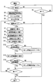
HCUでの覚醒刺激関連処理の流れの一例を示すフローチャートである。
ゆらぎコントローラの概略的な構成の一例を示す図である。
ゆらぎコントローラでのゆらぎの減衰の制御の一例について説明を行うための図である。
ゆらぎコントローラでのゆらぎの減衰の制御の一例について説明を行うための図である。
ゆらぎコントローラでのゆらぎの増幅の制御の一例について説明を行うための図である。
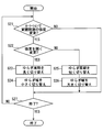
ゆらぎコントローラでのローテーション強調関連処理の流れの一例を示すフローチャートである。
図面を参照しながら、開示のための複数の実施形態及び変形例を説明する。なお、説明の便宜上、複数の実施形態及び変形例の間において、それまでの説明に用いた図に示した部分と同一の機能を有する部分については、同一の符号を付し、その説明を省略する場合がある。同一の符号を付した部分については、他の実施形態及び/又は変形例における説明を参照することができる。
(実施形態1)
<運転支援システム1の概略構成>
以下、本実施形態について図面を用いて説明する。図1に示す運転支援システム1は、自動車(以下、単に車両)で用いられるものであり、ADAS(Advanced Driver Assistance Systems)ロケータ2、周辺監視センサ3、HMI(Human Machine Interface)システム4、空調システム5、車両制御ECU6、及び運転支援ECU7を含んでいる。ADASロケータ2、周辺監視センサ3、HMIシステム4、空調システム5、車両制御ECU6、及び運転支援ECU7は、例えば車内LAN8に接続されているものとする。運転支援システム1を搭載している車両を以降では自車(Host vehicle)と呼ぶ。
<運転支援システム1の概略構成>
以下、本実施形態について図面を用いて説明する。図1に示す運転支援システム1は、自動車(以下、単に車両)で用いられるものであり、ADAS(Advanced Driver Assistance Systems)ロケータ2、周辺監視センサ3、HMI(Human Machine Interface)システム4、空調システム5、車両制御ECU6、及び運転支援ECU7を含んでいる。ADASロケータ2、周辺監視センサ3、HMIシステム4、空調システム5、車両制御ECU6、及び運転支援ECU7は、例えば車内LAN8に接続されているものとする。運転支援システム1を搭載している車両を以降では自車(Host vehicle)と呼ぶ。
ADASロケータ2は、GNSS(Global Navigation Satellite System)受信機、慣性センサ、地図データを格納した地図データベース(以下、DB)を備えている。GNSS受信機は、複数の人工衛星からの測位信号を受信する。慣性センサは、例えば3軸ジャイロセンサ及び3軸加速度センサを備える。地図DBは、不揮発性メモリであって、リンクデータ、ノードデータ、道路形状等の地図データを格納している。
ADASロケータ2は、GNSS受信機で受信する測位信号と、慣性センサの計測結果とを組み合わせることにより、ADASロケータ2を搭載した自車の車両位置を逐次測位する。なお、車両位置の測位には、自車に搭載された車輪速センサから逐次出力されるパルス信号から求めた走行距離等を用いる構成としてもよい。そして、測位した車両位置を車内LAN8へ出力する。また、ADASロケータ2は、地図DBから地図データを読み出し、車内LAN8へ出力することも行う。なお、地図データは、例えば自車に搭載されたDCM(Data Communication Module)といったテレマティクス通信に用いられる車載通信モジュールを用いて自車外のサーバから取得する構成としてもよい。
周辺監視センサ3は、歩行者、人間以外の動物、自転車、オートバイ、及び他車等の移動物体、さらに路上の落下物、ガードレール、縁石、及び樹木等の静止物体といった自車周辺の障害物を検出する。他にも、自車周辺の走行区画線、停止線等の路面標示を検出する。周辺監視センサ3は、例えば、自車周囲の所定範囲を撮像する周辺監視カメラ、自車周囲の所定範囲に探査波を送信するミリ波レーダ、ソナー、LIDAR(Light Detection and Ranging/Laser Imaging Detection and Ranging)等のセンサである。周辺監視カメラは、逐次撮像する撮像画像をセンシング情報として運転支援ECU7へ逐次出力する。ソナー、ミリ波レーダ、LIDAR等の探査波を送信するセンサは、障害物によって反射された反射波を受信した場合に得られる受信信号に基づく走査結果をセンシング情報として運転支援ECU7へ逐次出力する。なお、情報は、不可算名詞のみならず、可算名詞として使用される。情報は情報項目と同等であり、複数の情報は複数の情報項目と同等である。
HMIシステム4は、HCU(Human Machine Interface Control Unit)40、DSM(Driver Status Monitor)41、表示装置42、音声出力装置43、振動子44、及び操作デバイス45を備えている。HMIシステム4は、運転手からの入力操作を受け付けたり、運転手に向けて情報を提示したり、運転手の状態を監視したりする。この運転手は対象者とも言及される。
DSM41は、近赤外光源及び近赤外カメラと、これらを制御する制御ユニット等とによって構成されている。DSM41は、近赤外カメラを自車の運転席側に向けた姿勢にて、例えばインスツルメントパネルの上面に配置される。DSM41は、近赤外光源によって近赤外光を照射されたドライバの頭部を、近赤外カメラによって撮影する。近赤外カメラによる撮像画像は、制御ユニットによって画像解析される。制御ユニットは、例えばドライバの顔向き及び/又は視線方向を、撮像画像から検出する。
また、DSM41は、運転者の目の開き具合等を撮像画像から抽出し、運転者の覚醒度(つまり、眠気)を検知する。このDSM41は検知装置あるいはモニタ装置とも言及される。本実施形態では、DSM41において覚醒度を1~6の6段階の眠気に区分して検知する場合を例に挙げて説明を行う。6段階に区分される眠気は、覚醒度の高いものから順に、全く眠くなさそうな(言い換えると覚醒状態である)眠気「1」,やや眠そうな眠気「2」,眠そうな眠気「3」,かなり眠そうな眠気「4」,非常に眠そうな眠気「5」,眠っている(言い換えると睡眠状態である)眠気「6」とする。DSM41は、検知した眠気を車内LAN8へ出力する。
表示装置42としては、例えばコンビネーションメータ、CID(Center Information Display)、HUD(Head-Up Display)、LED等がある。この表示装置42は刺激装置とも言及される。コンビネーションメータは、運転席の前方に配置される。CIDは、車室内にてセンタクラスタの上方に配置される。コンビネーションメータは、HCU40から取得した画像データに基づいて、情報提示のための種々の画像を液晶ディスプレイの表示画面に表示する。HUDは、HCU40から取得した画像データに基づく画像の光を、ウインドシールドに規定された投影領域に投影する。ウインドシールドによって車室内側に反射された画像の光は、運転席に着座するドライバによって知覚される。ドライバは、HUDによって投影された画像の虚像を、自車前方の外界風景と重ねて視認可能となる。LEDは、インストルメントパネル等の運転手の目に付く位置に配置され、HCU40によって発光が制御される。
音声出力装置43としては、例えば音声を出力するオーディオスピーカ,音を出力するブザー等がある。この音声出力装置43は刺激装置とも言及される。振動子44は、例えばステアリングホイール,運転席のシート等の自車の運転手が接触する箇所に設けられ、運転手に振動による刺激を与える。振動子44は、HCU40によって振動が制御される。この振動子44は刺激装置とも言及される。
操作デバイス45は、操作スイッチ45とも言及され、運転手が操作するスイッチ群である。例えば、操作デバイス45としては、自車のステアリングのスポーク部に設けられたステアリングスイッチ,ディスプレイを有する表示装置42と一体となったタッチスイッチ等がある。本実施形態では、操作デバイス45に、覚醒を維持するための刺激(以下、覚醒刺激)の発生を運転手が要求するためのスイッチ(以下、刺激要求スイッチ)が含まれるものとして以降の説明を行う。この操作デバイス45のうちの刺激要求スイッチは操作入力器、操作入力スイッチとも言及される。
HCU40は、CPU、揮発性メモリ、不揮発性メモリ、I/O、これらを接続するバスを備え、不揮発性メモリに記憶された制御プログラムを実行することで各種の処理を実行する。このHCU40は覚醒維持装置とも言及される。HCU40での処理の詳細については後述する。
空調システム5は、自車の乗員によって設定された空調関連の設定値等を含む空調要求情報をHCU40から取得し、車室内の温度、清浄、及び気流等を調整する車両用の冷暖房システムである。空調システム5は、空調制御ECU50、エアコンユニット51、及びアロマユニット52を備えている。
エアコンユニット51は、インストルメントパネル等に設けられた吹出口から車室内に供給される温風及び冷風を生成する。アロマユニット52は、芳香(アロマ)成分を含むエッセンシャルオイル等のアロマオイルを霧状にする。芳香成分としては、覚醒効果がある成分を用いるものとする。アロマユニット52によって霧状にされた芳香成分は、エアコンユニット51によって生成された気流と混ぜられて車室内へと供給される。このエアコンユニット51及びアロマユニット52は、刺激装置とも言及される。
空調制御ECU50は、CPU、揮発性メモリ、不揮発性メモリ、I/O、これらを接続するバスを備え、不揮発性メモリに記憶された制御プログラムを実行することで各種の処理を実行する。空調制御ECU50は、車内LAN8と接続されており、HCU40から車内LAN8に出力された空調要求情報を受信する。空調制御ECU50は、エアコンユニット51及びアロマユニット52と接続されており、取得した空調要求情報に基づいて、エアコンユニット51及びアロマユニット52の作動を制御する。
車両制御ECU6は、自車の加減速制御及び/又は操舵制御を行う電子制御装置である。車両制御ECU6としては、操舵制御を行う操舵ECU、加減速制御を行うパワーユニット制御ECU及びブレーキECU等がある。車両制御ECU6は、自車に搭載されたアクセルポジションセンサ、ブレーキ踏力センサ、舵角センサ、車輪速センサ等の各センサから出力される検出信号を取得し、電子制御スロットル、ブレーキアクチュエータ、EPS(Electric Power Steering)モータ等の各走行制御デバイスへ制御信号を出力する。また、車両制御ECU6は、上述の各センサの検出信号を車内LAN8へ出力可能である。
運転支援ECU7は、揮発性メモリ、不揮発性メモリ、I/O、これらを接続するバスを備え、不揮発性メモリに記憶された制御プログラムを実行することで各種の処理を実行する。運転支援ECU7は、ADASロケータ2から取得した自車の車両位置及び地図データ、周辺監視センサ3から取得したセンシング情報等から、自車の走行環境を認識する。また、運転支援ECU7は、認識した走行環境をもとに、自動運転によって自車を走行させるための走行計画を生成する。例えば中長期の走行計画として、自車を目的地へ向かわせるための推奨経路を生成する。また、推奨経路に従った走行を行うための短期の走行計画を生成する。具体例としては、車線変更のための操舵、速度調整のための加減速、及び障害物回避のための操舵及び制動等の実行を決定する。そして、運転支援ECU7は、生成した走行計画に従い、自車の加速、制動、及び/又は操舵を車両制御ECU6に自動で行わせることで、自動運転を行わせる。
他にも、運転支援ECU7は、自動運転の自動化のレベル(以下、自動化レベル)を切り替えられるものとする。一例として、自動化レベルには、NHTSA(National Highway Traffic Safety Administration)が定義付けている分類に沿った、自動化レベル0(No-Automation)、自動化レベル1(Function-specific Automation)、自動化レベル2(Combined Function Automation)、自動化レベル3(Limited Self-Driving Automation)、自動化レベル4(Full Self-Driving Automation)の5段階が存在する。
自動化レベル0は、自車のブレーキ、ステアリング、スロットル、原動力といった主操縦系統について自動化を行わずにドライバが全て操作する段階である。言い換えると、加速、制動、及び操舵のいずれについても自動で制御しない自動運転不実施の段階である。つまり、手動運転の段階である。自動化レベル1は、自車の主操縦系統の1つを自動化した機能を単独で実行する段階である。言い換えると、加速、制動、及び操舵のいずれかを自動で制御する、特定機能の自動化の段階である。自動化レベル2は、自車の主操縦系統の1つを自動化した機能を複合して実行する段階である。言い換えると、加速、制動、及び操舵のうちの複数を自動で制御する、複合機能の自動化の段階である。自動化レベル3は、自車の主操縦系統の全てを自動化し、ドライバが運転すべき交通状況への変化時に限ってドライバが運転操作を行う段階である。言い換えると、緊急時を除いて、加速、制動、及び操舵の全てを自動で制御する、半自動運転の段階である。自動化レベル4は、自車の主操縦系統の全てを自動化し、走行中のいかなるときもドライバが運転操作を行う必要にない段階である。言い換えると、緊急時にも、加速、制動、及び操舵の全てを自動で制御する、完全自動運転の段階である。自動化レベル1~自動化レベル4については、加速、制動、及び操舵の少なくともいずれかを自動で制御する自動運転実施の段階と言うこともできる。
運転支援ECU7での自動運転の実施不実施の切り替えは、予定している自動運転区間の走行の終了、認識される走行環境若しくは周辺監視センサ3でのセンシングの不具合等に応じて、自律的に行われる構成とすればよい。他にも、操作デバイス45へのドライバによる入力操作に従って行われる構成としてもよい。また、自動化レベルを切り替える場合の段階分けは、前述した例に限らない。例えば、手動運転の段階、一部の運転操作を自動で行う段階、及び完全自動運転の段階といった段階分けであってもよいし、さらに他の段階分けであってもよい。
<HCU40の概略構成>
続いて、図2を用いて、HCU40の概略構成について説明を行う。HCU40は、トリガ検知回路401及び刺激制御回路402を備えており、刺激制御回路402は、ローテーションコントローラ403及びゆらぎコントローラ408を備えている。また、ローテーションコントローラ403は、順番コントローラ404、急峻さコントローラ405、変更周期コントローラ406、及び強度差コントローラ407を備えており、ゆらぎコントローラ408は、ゆらぎ周期コントローラ409及びゆらぎ幅コントローラ410を備えている。なお、HCU40が実行する機能の一部または全部を、一つあるいは複数のIC等によりハードウェア的に構成してもよい。なお、コントローラは、制御部とも言及される。
続いて、図2を用いて、HCU40の概略構成について説明を行う。HCU40は、トリガ検知回路401及び刺激制御回路402を備えており、刺激制御回路402は、ローテーションコントローラ403及びゆらぎコントローラ408を備えている。また、ローテーションコントローラ403は、順番コントローラ404、急峻さコントローラ405、変更周期コントローラ406、及び強度差コントローラ407を備えており、ゆらぎコントローラ408は、ゆらぎ周期コントローラ409及びゆらぎ幅コントローラ410を備えている。なお、HCU40が実行する機能の一部または全部を、一つあるいは複数のIC等によりハードウェア的に構成してもよい。なお、コントローラは、制御部とも言及される。
トリガ検知回路401は、トリガディテクタとも言及され、覚醒刺激を発生させるためのトリガを検知する。例えばトリガ検知回路401は、DSM41で検知した眠気が閾値以上であった場合に、これをトリガとして検知する。ここで言うところの閾値とは、運転手による運転操作を行う場合に、覚醒させる必要が生じる程度の眠気であって、一例としては眠気「3」とすればよい。
また、トリガ検知回路401は、操作デバイス45のうちの刺激要求スイッチで操作を受け付けた場合に、これをトリガとして検知する。刺激要求スイッチは、運転手が自らのタイミングで覚醒刺激を発生させたい場合に、運転手が操作を行うものとすればよい。運転手が自らのタイミングで覚醒刺激を発生させたい場合の一例としては、運転手が強い眠気を感じ始めたにも関わらず、DSM41で閾値以上の眠気が検知されず、覚醒刺激が発生しない場合等がある。
さらに、トリガ検知回路401は、運転支援ECU7をモニタすることにより、自動運転の自動化レベルが閾値以下に切り替わることをトリガとして検知する構成としてもよい。ここで言うところの閾値とは、運転手が覚醒する必要が生じる自動化レベルの切り替えの境目にあたるレベルとすればよい。一例としては、自動化レベル4から自動化レベル3以下への切り替わりといった、運転手による監視が必要となる境目にあたる自動化レベル3を閾値とすればよい。また、自動化レベル3以上から自動化レベル2以下への切り替わりといった、運転手による運転操作が必要となる境目にあたる自動化レベル2を閾値としてもよい。他にも、自動化レベル1以上(例えば自動化レベル3若しくは4)から自動化レベル0への切り替わりといった、自動運転から手動運転への境目にあたる自動化レベル0を閾値としてもよい。
また、トリガ検知回路401は、自動運転の自動化レベルが閾値以下に切り替わることをトリガとして検知する場合、自動化レベルが閾値以下に切り替わったことをトリガとして検知する構成としてもよいし、自動化レベルが閾値以下に切り替わることをトリガとして検知する構成としてもよい。自動化レベルが閾値以下に切り替わることをトリガとして検知する構成を採用する場合には、運転支援ECU7で生成する走行計画から、自動化レベルが閾値以下に切り替わることを予め予測し、自動化レベルが閾値以下に切り替わるタイミングよりも前にトリガを検知すればよい。自動化レベルが閾値以下に切り替わるタイミングよりもどの程度前にトリガを検知するかは、任意に設定可能とすればよい。例えば4秒前等としてもよいし、100m前等としてもよい。
刺激制御回路402は、刺激電子制御ユニットとも言及され、トリガ検知回路401でトリガを検知した場合に、覚醒刺激を発生する複数の刺激装置から、覚醒刺激を同時に発生させる。刺激装置としては、表示装置42、音声出力装置43、振動子44、エアコンユニット51、及びアロマユニット52がある。刺激制御回路402は、エアコンユニット51及びアロマユニット52については、空調制御ECU50へ向けて空調要求情報を出力することにより作動を制御する。
表示装置42から発生させる覚醒刺激は、一例としてLEDの発光とする。音声出力装置43から発生させる覚醒刺激は、一例としてアラーム音とする。振動子44から発生させる覚醒刺激は、一例として振動とする。エアコンユニット51から発生させる覚醒刺激は、一例として冷風とする。アロマユニット52から発生させる覚醒刺激は、一例として覚醒効果のある芳香とする。
また、刺激制御回路402は、前述したようにローテーションコントローラ403及びゆらぎコントローラ408を備え、ローテーションコントローラ403によって、複数の刺激装置からそれぞれ発生させる覚醒刺激の強度が順番に強くなるように覚醒刺激の強度を変更させる(つまり、ローテーションさせる)。さらに、刺激制御回路402は、ゆらぎコントローラ408によって、複数の刺激装置からそれぞれ発生させる覚醒刺激の各々の強度にゆらぎが生じるように覚醒刺激の強度を変更させる。ここで言うところのゆらぎとは、覚醒刺激の強度が、基準となる強度を中心に周期的に上下に変動する状態を示す。
表示装置42から発生させる覚醒刺激の強度を変更させる場合は、一例としてLEDの発光の強度を変更させる構成とすればよい。音声出力装置43から発生させる覚醒刺激の強度を変更させる場合には、一例としてアラーム音の音量を変更させる構成とすればよい。振動子44から発生させる覚醒刺激を変更させる場合には、一例として振動の強度を変更させる構成とすればよい。エアコンユニット51から発生させる覚醒刺激を変更させる場合には、一例として冷風の温度若しくは風量を変更させる構成とすればよい。アロマユニット52から発生させる覚醒刺激を変更させる場合には、一例として芳香の濃度を変更させる構成とすればよい。
ここで、図3~図7を用いて、ローテーションコントローラ403での覚醒刺激の強度の制御について説明を行う。図3~7では、便宜上、覚醒刺激の種類は覚醒刺激A~Cの3種類である場合を例に挙げて説明を行う。図3~図7のグラフの縦軸が強度を示しており、横軸が時間を示している。
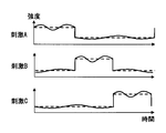
まず、ローテーションコントローラ403は、図3に示すように、複数種類の覚醒刺激の強度をローテーションで順に強くしていく。つまり、複数の刺激装置からそれぞれ発生させる覚醒刺激の発生態様を逐次変更させる。なお、ローテーションコントローラ403では、ある種類の覚醒刺激の強度を強くしている場合には、他の種類の覚醒刺激の強度は弱くしている。図3では、覚醒刺激A,覚醒刺激B,覚醒刺激Cの順に強度を強くしていく場合の例を示している。
さらに、ローテーションコントローラ403は、順番コントローラ404、急峻さコントローラ405、変更周期コントローラ406、及び強度差コントローラ407により、各刺激装置で覚醒刺激の強度を強くするタイミング,強度の大きさ,強度の時間変化率(つまり、急峻さ)を制御し、切り替える。ローテーションコントローラ403は、この切り替えによっても、複数の刺激装置からそれぞれ発生させる覚醒刺激の発生態様を変更させる。
順番コントローラ404は、各刺激装置から覚醒刺激を発生させるローテーションの順番を制御する。一例として、順番コントローラ404は、HCU40の不揮発性メモリに予め記憶されているローテーションの順番についてのデフォルトの設定値に従い、ローテーションの順番を制御する構成とすればよい。
また、順番コントローラ404は、所定の条件を満たした場合に、図4に示すように、複数の刺激装置からそれぞれ発生させる覚醒刺激の強度をローテーションで順番に強くしていく際の、この順番を切り替える。所定の条件の一例については後述する。図4では、覚醒刺激A,覚醒刺激B,覚醒刺激Cの順番であったローテーションを、覚醒刺激C,覚醒刺激B,覚醒刺激Aの順番に切り替える場合の例を示している。順番コントローラ404は、ローテーションの順番を、ランダムに切り替える構成としてもよいし、デフォルトの設定値と逆の順番に切り替える構成としてもよい。
急峻さコントローラ405は、各刺激装置から発生させる覚醒刺激の強度をローテーションで強く変更していく際の強度変化の急峻さを制御する。一例として、急峻さコントローラ405は、HCU40の不揮発性メモリに予め記憶されている覚醒刺激の強度を変化させる際の時間変化率のデフォルトの設定値に従い、ローテーションの順番を制御する構成とすればよい。
また、急峻さコントローラ405は、所定の条件を満たした場合に、図5に示すように、複数の刺激装置からそれぞれ発生させる覚醒刺激の強度変化の急峻さを切り替える。所定の条件の一例については後述する。図5では、覚醒刺激の強度変化の急峻さが大きくなるように切り替える場合の例を示している。強度変化の急峻さの切り替えは、急峻さが大きくなるように切り替える構成としてもよいし、急峻さが小さくなるように切り替える構成としてもよいし、急峻さをランダムに切り替える構成としてもよい。
変更周期コントローラ406は、各刺激装置からそれぞれ発生させる覚醒刺激の強度をローテーションで強く変更していく際の変更の周期(以下、変更周期)を制御する。一例として、変更周期コントローラ406は、HCU40の不揮発性メモリに予め記憶されている変更周期のデフォルトの設定値に従い、変更周期を制御する構成とすればよい。
また、変更周期コントローラ406は、所定の条件を満たした場合に、図6に示すように、複数の刺激装置からそれぞれ発生させる覚醒刺激の変更周期を切り替える。所定の条件の一例については後述する。図6では、切り替え前の変更周期Pc1に比べ、切り替え後の変更周期Pc2が短くなるように切り替える場合の例を示している。変更周期の切り替えは、変更周期が短くなるように切り替える構成としてもよいし、変更周期が長くなるように切り替える構成としてもよいし、変更周期をランダムに切り替える構成としてもよい。
強度差コントローラ407は、各刺激装置からそれぞれ発生させる覚醒刺激の強度をローテーションで強く変更していく際の、各々の覚醒刺激の上限と下限との強度差(以下、変更強度差)を制御する。変更強度差は、ローテーションで覚醒刺激の強度を強弱2つのパターンに変化させる際の、強度を強くしているときと強度を弱くしているときの強度差と言い換えることもできる。一例として、強度差コントローラ407は、HCU40の不揮発性メモリに予め記憶されている変更強度差のデフォルトの設定値に従い、変更強度差を制御する構成とすればよい。
また、強度差コントローラ407は、所定の条件を満たした場合に、図7に示すように、複数の刺激装置からそれぞれ発生させる覚醒刺激の変更強度差を切り替える。所定の条件の一例については後述する。図7では、切り替え前の変更強度差Id1に比べ、切り替え後の変更強度差Id2が大きくなるように切り替える場合の例を示している。変更強度差の切り替えは、変更強度差が大きくなるように切り替える構成としてもよいし、変更強度差が小さくなるように切り替える構成としてもよいし、変更強度差をランダムに切り替える構成としてもよい。また、強度の上限のみを変化させることで変更強度差を切り替える構成としてもよいし、強度の下限のみを変化させることで変更強度差を切り替える構成としてもよいし、強度の上限と下限との両方を変化させることで変更強度差を切り替える構成としてもよい。
なお、急峻さコントローラ405,変更周期コントローラ406,強度差コントローラ407によって制御する急峻さ,変更周期,変更強度差については、覚醒刺激の種類ごとに異なる値であってもよい。
続いて、図8~図12を用いて、ゆらぎコントローラ408での覚醒刺激の強度の制御について説明を行う。図8~図10でも、便宜上、覚醒刺激の種類は覚醒刺激A~Cの3種類である場合を例に挙げて説明を行う。図8~図12のグラフの縦軸が強度を示しており、横軸が時間を示している。
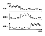
まず、ゆらぎコントローラ408は、図8に示すように、複数の刺激装置からそれぞれ発生させる覚醒刺激の各々の強度にゆらぎが生じるように覚醒刺激の強度を変更させる。つまり、複数の刺激装置からそれぞれ発生させる覚醒刺激の発生態様を逐次変更させる。図8では、覚醒刺激A,覚醒刺激B,覚醒刺激Cのそれぞれについて、ローテーションコントローラ403での制御に用いる設定値に従った強度(図8中の破線参照)を基準として、この基準を中心に周期的に強度を上下に変動させる場合の例を示している。
ゆらぎ周期コントローラ409は、各刺激装置からそれぞれ発生させる覚醒刺激の各々の強度にゆらぎが生じるように覚醒刺激の強度を変更させる際の、このゆらぎの周期を(以下、ゆらぎ周期)を制御する。一例として、ゆらぎ周期コントローラ409は、HCU40の不揮発性メモリに予め記憶されているゆらぎ周期のデフォルトの設定値に従い、ゆらぎ周期を制御する構成とすればよい。
また、ゆらぎ周期コントローラ409は、所定の条件を満たした場合に、図9に示すように、各刺激装置からそれぞれ発生させる覚醒刺激のゆらぎ周期を切り替える。所定の条件の一例については後述する。図9では、切り替え前のゆらぎ周期Pc3に比べ、切り替え後のゆらぎ周期Pc4が短くなるように切り替える場合の例を示している。ゆらぎ周期の切り替えは、ゆらぎ周期が短くなるように切り替える構成としてもよいし、ゆらぎ周期が長くなるように切り替える構成としてもよいし、ゆらぎ周期をランダムに切り替える構成としてもよい。
さらに、ゆらぎ周期コントローラ409は、ゆらぎ周期(図10のPc5参照)を切り替える場合に、切り替え後のゆらぎ周期と、変更周期コントローラ406で制御されている変更周期(図10のPc6参照)とを比較する。そして、ゆらぎ周期が変更周期以上であった場合には、切り替え後のゆらぎ周期を、変更周期よりも短いゆらぎ周期に変更する。つまり、ゆらぎ周期コントローラ409は、ゆらぎ周期を切り替える場合に、ゆらぎ周期が変更周期よりも短くなるようにゆらぎ周期を切り替える。これは、ゆらぎ周期が変更周期以上の長さとなった場合、変更周期コントローラ406での覚醒刺激の強度のローテーションとゆらぎ周期コントローラ409での覚醒刺激の強度のゆらぎとが、運転手に混同され、強度のローテーションとゆらぎとの相乗効果による覚醒状態の維持の効果が弱まるためである。
ゆらぎ幅コントローラ410は、各刺激装置からそれぞれ発生させる覚醒刺激の各々の強度にゆらぎが生じるように覚醒刺激の強度を変更させる際の、このゆらぎにおける覚醒刺激の強度のゆらぎ幅を制御する。ゆらぎ幅は、ゆらぎにおける覚醒刺激の強度の上限と下限との強度差と言い換えることもできる。一例として、ゆらぎ幅コントローラ410は、HCU40の不揮発性メモリに予め記憶されているゆらぎ幅のデフォルトの設定値に従い、ゆらぎ幅を制御する構成とすればよい。
また、ゆらぎ幅コントローラ410は、所定の条件を満たした場合に、図11に示すように、各刺激装置からそれぞれ発生させる覚醒刺激のゆらぎ幅を切り替える。所定の条件の一例については後述する。図11では、切り替え前のゆらぎ幅Id3に比べ、切り替え後のゆらぎ幅Id4が大きくなるように切り替える場合の例を示している。ゆらぎ幅の切り替えは、ゆらぎ幅が大きくなるように切り替える構成としてもよいし、ゆらぎ幅が小さくなるように切り替える構成としてもよいし、ゆらぎ幅をランダムに切り替える構成としてもよい。また、ゆらぎ幅の上限のみを変化させることでゆらぎ幅を切り替える構成としてもよいし、ゆらぎ幅の下限のみを変化させることでゆらぎ幅を切り替える構成としてもよいし、ゆらぎ幅の上限と下限との両方を変化させることでゆらぎ幅を切り替える構成としてもよい。
さらに、ゆらぎ幅コントローラ410は、ゆらぎ幅(図12のId5参照)を切り替える場合に、切り替え後のゆらぎ幅と、強度差コントローラ407で制御されている変更強度差(図12のId6参照)とを比較する。そして、ゆらぎ幅が変更強度差以上であった場合には、切り替え後のゆらぎ幅を、変更強度差よりも強度の上限と下限との差が小さいゆらぎ幅に変更する。つまり、ゆらぎ幅コントローラ410は、ゆらぎ幅を切り替える場合に、ゆらぎ幅が変更強度差よりも小さくなるようにゆらぎ幅を切り替える。これは、ゆらぎ幅が変更強度差以上の大きさとなった場合、強度差コントローラ407での覚醒刺激の強度のローテーションとゆらぎ幅コントローラ410での覚醒刺激の強度のゆらぎとが、運転手に混同され、強度のローテーションとゆらぎとの相乗効果による覚醒状態の維持の効果が弱まるためである。
<HCU40での覚醒刺激関連処理>
続いて、図13のフローチャートを用いて、HCU40での覚醒刺激を発生させる制御に関連する処理(以下、覚醒刺激関連処理)の流れの一例について説明を行う。図13のフローチャートは、例えば、自車のイグニッション電源がオンになったときにHCU40の電源もオンになり開始する構成とすればよい。
続いて、図13のフローチャートを用いて、HCU40での覚醒刺激を発生させる制御に関連する処理(以下、覚醒刺激関連処理)の流れの一例について説明を行う。図13のフローチャートは、例えば、自車のイグニッション電源がオンになったときにHCU40の電源もオンになり開始する構成とすればよい。
記載されるフローチャートは、複数のセクション(あるいはステップと言及される)を含み、各セクションは、たとえば、S1と表現される。さらに、各セクションは、複数のサブセクションに分割されることができる、一方、複数のセクションが合わさって一つのセクションにすることも可能である。各セクションは、デバイス、モジュール、ユニット、あるいは、固有名として、も言及される。例えば、検出セクションは、検出デバイス、検出モジュール、検出器、あるいは、ディテクタとして、言及されることができる。また、セクションは、(i)ハードウエアユニット(例えば、コンピュータ)と組み合わさったソフトウエアのセクションのみならず、(ii)ハードウエア(例えば、集積回路、配線論理回路)のセクションとして、関連する装置の機能を含みあるいは含まずに実現できる。さらに、ハードウエアのセクションは、マイクロコンピュータの内部に含まれることもできる。
まず、S1では、トリガ検知回路401が、覚醒刺激を発生させるためのトリガを検知した場合(S1でYES)には、S3に移る。一方、トリガを検知していない場合(S1でNO)には、S2に移る。S2では、覚醒刺激関連処理の終了タイミングであった場合(S2でYES)には、覚醒刺激関連処理を終了する。一方、覚醒刺激関連処理の終了タイミングでなかった場合(S2でNO)には、S1に戻って処理を繰り返す。覚醒刺激関連処理の終了タイミングの一例としては、自車のイグニッション電源がオフになったこと,完全自動運転に切り替わったこと等がある。
S3では、刺激制御回路402が、複数の刺激装置から、覚醒刺激を同時に発生させる。S4では、ローテーションコントローラ403が、各刺激装置から発生させる覚醒刺激の強度をローテーションさせる。つまり、各刺激装置から発生させる覚醒刺激にローテーションを付加する。また、覚醒刺激の強度をローテーションさせる際の順番,強度変化の急峻さ,変更周期,変更強度差については、デフォルトの設定値に従って順番コントローラ404、急峻さコントローラ405、変更周期コントローラ406、及び強度差コントローラ407で制御される。
S5では、ゆらぎコントローラ408が、各刺激装置から発生させる各覚醒刺激の強度にゆらぎを生じさせる。つまり、各刺激装置から発生させる覚醒刺激にゆらぎを付加する。また、覚醒刺激の強度にゆらぎを生じさせる際のゆらぎ周期,ゆらぎ幅については、デフォルトの設定値に従ってゆらぎ周期コントローラ409及びゆらぎ幅コントローラ410で制御される。
S6では、トリガ検知回路401が、DSM41で検知した眠気が閾値以上であったことをトリガとして検知するか、若しくは刺激要求スイッチで操作を受け付けたことをトリガとして検知した場合に、刺激制御回路402が運転手の眠気あり(S6でYES)と判断し、S7に移る。つまり、これまでの覚醒刺激では覚醒効果が乏しいものとして、S7に移る。一方、トリガ検知回路401が、いずれもトリガとして検知していない場合には、運転手の眠気なし(S6でNO)と判断して、覚醒刺激関連処理を終了する。つまり、覚醒刺激によって運転手が覚醒状態となったものとして覚醒刺激関連処理を終了する。
S7では、順番コントローラ404が、各刺激装置からそれぞれ発生させる覚醒刺激の強度をローテーションで順番に強くしていく際のこの順番を、それまでの順番から切り替える。S8では、変更周期コントローラ406が、各刺激装置からそれぞれ発生させる覚醒刺激の変更周期を、それまでの変更周期から切り替える。覚醒効果を高めるためには、変更周期が短くなるように切り替えることが好ましい。
S9では、強度差コントローラ407が、各刺激装置からそれぞれ発生させる覚醒刺激の変更強度差を、それまでの変更強度差から切り替える。覚醒効果を高めるためには、変更強度差が大きくなるように切り替えることが好ましい。S10では、急峻さコントローラ405が、各刺激装置からそれぞれ発生させる覚醒刺激の強度変化の急峻さを、それまでの急峻さから切り替える。覚醒効果を高めるためには、急峻さが増すように切り替えることが好ましい。
S11では、ゆらぎ幅コントローラ410が、各刺激装置からそれぞれ発生させる覚醒刺激のゆらぎ幅を、それまでのゆらぎ幅から切り替える。覚醒効果を高めるためには、ゆらぎ幅が大きくなるように切り替えることが好ましい。
S12では、ゆらぎ幅コントローラ410が、S11で切り替え後のゆらぎ幅と、強度差コントローラ407で制御されている現在の変更強度差とを比較する。そして、ゆらぎ幅が変更強度差未満であった場合(S12でYES)には、S14に移る。一方、ゆらぎ幅が変更強度差以上であった場合(S12でNO)には、S13に移る。S13では、ゆらぎ幅コントローラ410が、S11で切り替え後のゆらぎ幅を、S11で切り替え前のゆらぎ幅とは異なるようにしつつ、現在の変更強度差よりも小さくなるように変更する。
S14では、ゆらぎ周期コントローラ409が、各刺激装置からそれぞれ発生させる覚醒刺激のゆらぎ周期を、それまでのゆらぎ周期から切り替える。覚醒効果を高めるためには、ゆらぎ周期が短くなるように切り替えることが好ましい。
S15では、ゆらぎ周期コントローラ409が、S14で切り替え後のゆらぎ周期と、変更周期コントローラ406で制御されている現在の変更周期とを比較する。そして、ゆらぎ周期が変更周期未満であった場合(S15でYES)には、S17に移る。一方、ゆらぎ周期が変更周期以上であった場合(S15でNO)には、S16に移る。S16では、ゆらぎ周期コントローラ409が、S14で切り替え後のゆらぎ周期を、S14で切り替え前のゆらぎ周期とは異なるようにしつつ、現在の変更周期よりも短くなるように変更する。
S17では、覚醒刺激関連処理の終了タイミングであった場合(S17でYES)には、各刺激装置からの覚醒刺激の発生を終了させ、覚醒刺激関連処理を終了する。一方、覚醒刺激関連処理の終了タイミングでなかった場合(S17でNO)には、S6に戻って処理を繰り返す。
なお、図13のフローチャートでは、S6で刺激制御回路402が運転手の眠気ありと判断した場合に、覚醒刺激の強度をローテーションさせる際の順番,強度変化の急峻さ,変更周期,変更強度差、並びに覚醒刺激の強度にゆらぎを生じさせる際のゆらぎ周期,ゆらぎ幅といった覚醒刺激の発生態様の全てを切り替える構成を示したが、必ずしもこれに限らない。例えば、覚醒刺激の発生態様を1種類ずつ切り替えながら、その都度刺激制御回路402が運転手の眠気ありか否かを判断し、運転手の眠気ありとの判断が続く場合に、切り替える覚醒刺激の発生態様の種類を逐一増やしていく構成としてもよい。また、図13のフローチャートにおけるS12及びS13の処理を省略する構成としてもよいし、S15及びS16の処理を省略する構成としてもよい。他にも、覚醒刺激の発生態様を切り替えた後にS6で刺激制御回路402が運転手の眠気なしと判断した場合に、その時点で覚醒刺激の制御に用いている設定値を、新たなデフォルトの設定値として設定し直す構成としてもよい。
<実施形態1のまとめ>
実施形態1の構成によれば、複数種類の覚醒刺激を同時に発生させるので、単一の刺激を発生させる場合に比べて運転手が刺激に慣れにくい。また、複数種類の覚醒刺激の強度をローテーションさせたり、ゆらぎを生じさせたりするので、それぞれの覚醒刺激についての慣れも生じにくい。さらに、覚醒刺激による覚醒効果が薄れた場合に、覚醒刺激の強度をローテーションさせる際の順番,強度変化の急峻さ,変更周期,変更強度差、並びに覚醒刺激の強度にゆらぎを生じさせる際のゆらぎ周期,ゆらぎ幅を、切り替えるので、覚醒刺激についての慣れが非常に生じにくくなる。特に、覚醒刺激の強度をローテーションさせる際の順番の切り替えは、運転手が認識しやすいと考えられることから、運転手が違和感を生じやすく、特に覚醒刺激への慣れが生じにくくなると考えられる。以上のように、本実施形態の構成によれば、覚醒刺激への慣れがより生じにくくなるため、ドライバの覚醒効果をより長い時間継続させることが可能になる。
実施形態1の構成によれば、複数種類の覚醒刺激を同時に発生させるので、単一の刺激を発生させる場合に比べて運転手が刺激に慣れにくい。また、複数種類の覚醒刺激の強度をローテーションさせたり、ゆらぎを生じさせたりするので、それぞれの覚醒刺激についての慣れも生じにくい。さらに、覚醒刺激による覚醒効果が薄れた場合に、覚醒刺激の強度をローテーションさせる際の順番,強度変化の急峻さ,変更周期,変更強度差、並びに覚醒刺激の強度にゆらぎを生じさせる際のゆらぎ周期,ゆらぎ幅を、切り替えるので、覚醒刺激についての慣れが非常に生じにくくなる。特に、覚醒刺激の強度をローテーションさせる際の順番の切り替えは、運転手が認識しやすいと考えられることから、運転手が違和感を生じやすく、特に覚醒刺激への慣れが生じにくくなると考えられる。以上のように、本実施形態の構成によれば、覚醒刺激への慣れがより生じにくくなるため、ドライバの覚醒効果をより長い時間継続させることが可能になる。
また、実施形態1の構成によれば、トリガ検知回路401でトリガを検知した場合に覚醒刺激を発生させるため、常に覚醒刺激を発生させ続ける構成に比べ、運転手が覚醒刺激を与えられる機会が少なく、覚醒刺激への慣れが生じにくい。さらに、本実施形態の構成によれば、自動運転の自動化レベルが閾値以下に切り替わることをトリガとしてトリガ検知回路401が検知する。よって、自動運転中に監視,運転操作が軽減されることにより運転手の覚醒度が低下していた場合でも、自動化レベルが下がって運転手の監視,運転操作等が必要となる際には覚醒させることが可能になる。
(実施形態2)
また、実施形態1に示した構成に限らず、ローテーションコントローラ403での覚醒刺激の強度の変更に合わせて、ゆらぎの減衰及び増幅を行う構成(以下、実施形態2)としてもよい。以下、実施形態2の構成について説明する。
また、実施形態1に示した構成に限らず、ローテーションコントローラ403での覚醒刺激の強度の変更に合わせて、ゆらぎの減衰及び増幅を行う構成(以下、実施形態2)としてもよい。以下、実施形態2の構成について説明する。
実施形態2の運転支援システム1は、HCU40の刺激制御回路402にゆらぎコントローラ408の代わりにゆらぎコントローラ408aを備える点を除けば、実施形態1の運転支援システム1と同様である。ここで、図14を用いて、ゆらぎコントローラ408aの概略構成を説明する。
図14に示すように、ゆらぎコントローラ408aは、ゆらぎ周期コントローラ409a及びゆらぎ幅コントローラ410aを備えている。ゆらぎ周期コントローラ409a及びゆらぎ幅コントローラ410aは、ローテーションコントローラ403での覚醒刺激の強度の変更に合わせてゆらぎの減衰及び増幅を行う点を除けば、実施形態1のゆらぎ周期コントローラ409及びゆらぎ幅コントローラ410と同様である。以下では、実施形態1のゆらぎ周期コントローラ409及びゆらぎ幅コントローラ410と異なる、ゆらぎ周期コントローラ409a及びゆらぎ幅コントローラ410aでの、このゆらぎの減衰及び増幅に関する構成について説明を行う。なお、コントローラは制御部とも言及される。
まず、ゆらぎ周期コントローラ409aは、図14に示すように、ゆらぎ周期延長器4091及びゆらぎ周期短縮器4092を備えている。ゆらぎ周期延長器4091は、ローテーションコントローラ403で覚醒刺激の強度を弱く変更する場合に、ゆらぎ周期をこの変更前よりも長く切り替える。ゆらぎ周期が長く切り替わることにより、運転手にとってゆらぎがより目立たなくなり、覚醒刺激の強度の変更を運転手がより認識しやすくなる。ゆらぎ周期短縮器4092は、ローテーションコントローラ403で覚醒刺激の強度を強く変更する場合に、ゆらぎ周期をこの変更前よりも短く切り替える。ゆらぎ周期が短く切り替わることにより、覚醒刺激の強度の変更を運転手がより認識しやすくなる。なお、ゆらぎ周期コントローラ409aは、ゆらぎ周期を切り替える場合に、ゆらぎ周期が変更周期コントローラ406で制御されている変更周期よりも短くなるようにゆらぎ周期を切り替えることが好ましい。
続いて、ゆらぎ幅コントローラ410aは、図14に示すように、ゆらぎ幅減衰器4101及びゆらぎ幅増幅器4102を備えている。ゆらぎ幅減衰器4101は、ローテーションコントローラ403で覚醒刺激の強度を弱く変更する場合に、ゆらぎ幅をこの変更前よりも小さく切り替える。ゆらぎ幅が小さく切り替わることにより、運転手にとってゆらぎがより目立たなくなり、覚醒刺激の強度の変更を運転手がより認識しやすくなる。ゆらぎ幅増幅器4102は、ローテーションコントローラ403で覚醒刺激の強度を強く変更する場合に、ゆらぎ幅をこの変更前よりも大きく切り替える。ゆらぎ幅が大きく切り替わることにより、覚醒刺激の強度の変更を運転手がより認識しやすくなる。なお、ゆらぎ幅コントローラ410aは、ゆらぎ幅を切り替える場合に、ゆらぎ幅が強度差コントローラ407で制御されている変更強度差よりも小さくなるようにゆらぎ幅を切り替えることが好ましい。
ゆらぎコントローラ408aは、ローテーションコントローラ403で覚醒刺激の強度を弱く変更する場合に、図15に示すように、ゆらぎ自体を止めることで覚醒刺激の強度の変更を運転手により認識しやすくしてもよい。他にも、ゆらぎコントローラ408aは、ローテーションコントローラ403で覚醒刺激の強度を弱く変更する場合に、図16に示すように、ゆらぎ周期をより長く切り替えるとともにゆらぎ幅をより小さく切り替えることで覚醒刺激の強度の変更を運転手により認識しやすくしてもよい。また、ゆらぎコントローラ408aは、ローテーションコントローラ403で覚醒刺激の強度を強く変更する場合に、図17に示すように、ゆらぎ周期をより短く切り替えるとともにゆらぎ幅をより大きく切り替えることで覚醒刺激の強度の変更を運転手により認識しやすくしてもよい。
ここで、図18を用いて、ローテーションコントローラ403での覚醒刺激の強度の変更に合わせたゆらぎコントローラ408aでのゆらぎの減衰及び増幅に関する処理(以下、ローテーション強調関連処理)の流れの一例について説明を行う。図18では、ローテーションで覚醒刺激の強度を弱く変更する場合に、ゆらぎ周期をより長く切り替えるとともにゆらぎ幅をより小さく切り替える一方、ローテーションで覚醒刺激の強度を強く変更する場合に、ゆらぎ周期をより短く切り替えるとともにゆらぎ幅をより大きく切り替える場合を例に挙げて説明を行う。
図18のフローチャートは、HCU40の覚醒刺激関連処理で各刺激装置から発生させる覚醒刺激にローテーションを付加した場合に開始する構成とすればよい。ローテーション強調関連処理は、各刺激装置のそれぞれでの覚醒刺激のローテーションについて行う構成とすればよい。
まず、S21では、ローテーションコントローラ403での覚醒刺激の強度の変更がある場合(S21でYES)には、S22に移る。一方、ローテーションコントローラ403での覚醒刺激の強度の変更がない場合(S21でNO)には、S27に移る。S22では、覚醒刺激の強度の変更が強度を弱くする変更である場合(S22でYES)には、S23に移る。一方、覚醒刺激の強度の変更が強度を強くする変更である場合(S22でNO)には、S25に移る。
S23では、ゆらぎ周期延長器4091が、覚醒刺激の強度を弱くする刺激装置について、ゆらぎ周期を覚醒刺激の強度の変更前よりも長く切り替える。S24では、ゆらぎ幅減衰器4101が、覚醒刺激の強度を弱くする刺激装置について、ゆらぎ幅を覚醒刺激の強度の変更前よりも小さく切り替え、S27に移る。
一方、S25では、ゆらぎ周期短縮器4092が、覚醒刺激の強度を強くする刺激装置について、ゆらぎ周期を覚醒刺激の強度の変更前よりも短く切り替える。S26では、ゆらぎ幅増幅器4102が、覚醒刺激の強度を強くする刺激装置について、ゆらぎ幅を覚醒刺激の強度の変更前よりも大きく切り替え、S27に移る。
S27では、ローテーション強調関連処理の終了タイミングであった場合(S27でYES)には、ローテーション強調関連処理を終了する。一方、ローテーション強調関連処理の終了タイミングでなかった場合(S27でNO)には、S21に戻って処理を繰り返す。ローテーション強調関連処理の終了タイミングの一例としては、HCU40の覚醒刺激関連処理が終了したこと等がある。
以上の構成によれば、実施形態1の構成による効果に加え、ゆらぎを覚醒刺激に付加しながらも覚醒刺激の強度の変更を運転手がより認識しやすくなるという効果を奏することが可能になる。詳しくは、覚醒刺激の強度が強弱変化する際の、弱の時にはゆらぎを減衰したり、強の時にはゆらぎを増幅したりすることで、覚醒刺激の強度のローテーションに注意を向けさせることで、覚醒刺激の強度のローテーションを運転手に認識しやすくする。従って、覚醒刺激のローテーションとゆらぎといった2種類の覚醒刺激の慣れ防止の両方の高い効果が期待でき、運転手の覚醒度を高く維持することが可能になる。
なお、ここでは、ゆらぎの減衰及び増幅のいずれも行う構成を示したが、必ずしもこれに限らない。例えば、ゆらぎの減衰及び増幅のうちのいずれか一方を行うことによって、覚醒刺激の強度のローテーションを運転手に認識しやすくする構成であっても構わない。また、ここでは、ゆらぎの減衰及び増幅を、ゆらぎ周期及びゆらぎ幅の切り替えによって行う構成を示したが、必ずしもこれに限らない。例えば、ゆらぎの減衰及び増幅を、ゆらぎ周期及びゆらぎ幅のいずれか一方の切り替えによって行う構成としても構わない。
ゆらぎ周期及びゆらぎ幅のいずれか一方の切り替えのみを行う場合には、ゆらぎ幅の切り替えの方が覚醒刺激の強度の変化に運転手が気づきやすくなるため、ゆらぎ幅の切り替えを行う構成の方がより好ましい。また、ゆらぎの減衰としてゆらぎ自体を止めることで、覚醒刺激の強度の変化に運転手がより気づきやすくなるため、ゆらぎの減衰としてゆらぎ自体を止めることがより好ましい。
(変形例1)
前述の実施形態では、ローテーションコントローラ403が、覚醒刺激の強度をローテーションさせる際の順番、強度変化の急峻さ、変更周期、及び変更強度差を切り替える構成を示したが、必ずしもこれに限らない。例えば、覚醒刺激の強度をローテーションさせる際の順番、強度変化の急峻さ、変更周期、及び変更強度差のうちの一部のみを切り替える構成としてもよい。
前述の実施形態では、ローテーションコントローラ403が、覚醒刺激の強度をローテーションさせる際の順番、強度変化の急峻さ、変更周期、及び変更強度差を切り替える構成を示したが、必ずしもこれに限らない。例えば、覚醒刺激の強度をローテーションさせる際の順番、強度変化の急峻さ、変更周期、及び変更強度差のうちの一部のみを切り替える構成としてもよい。
(変形例2)
前述の実施形態では、ゆらぎコントローラ408が、覚醒刺激の強度にゆらぎを生じさせる際のゆらぎ周期及びゆらぎ幅を切り替える構成を示したが、必ずしもこれに限らない。例えば、覚醒刺激の強度にゆらぎを生じさせる際のゆらぎ周期及びゆらぎ幅のうちのいずれかのみを切り替える構成としてもよい。
前述の実施形態では、ゆらぎコントローラ408が、覚醒刺激の強度にゆらぎを生じさせる際のゆらぎ周期及びゆらぎ幅を切り替える構成を示したが、必ずしもこれに限らない。例えば、覚醒刺激の強度にゆらぎを生じさせる際のゆらぎ周期及びゆらぎ幅のうちのいずれかのみを切り替える構成としてもよい。
(変形例3)
前述の実施形態では、刺激制御回路402がローテーションコントローラ403とゆらぎコントローラ408とを備える構成を示したが、必ずしもこれに限らない。例えば、刺激制御回路402がローテーションコントローラ403とゆらぎコントローラ408とのいずれか一方のみを備える構成としてもよい。
前述の実施形態では、刺激制御回路402がローテーションコントローラ403とゆらぎコントローラ408とを備える構成を示したが、必ずしもこれに限らない。例えば、刺激制御回路402がローテーションコントローラ403とゆらぎコントローラ408とのいずれか一方のみを備える構成としてもよい。
(変形例4)
前述の実施形態では、覚醒刺激として、光、音、振動、風、及び芳香を用いる場合を例に挙げて説明を行ったが、必ずしもこれに限らない。覚醒刺激の種類が複数種類であれば、光、音、振動、風、及び芳香のうちの一部を用いる構成としてもよいし、他の種類の覚醒刺激を用いる構成としてもよい。また、複数種類の刺激としては、生じる感覚が異なる刺激を複数種類の刺激として用いる構成に限らず、刺激を行う人体の部位が異なる刺激を複数種類の刺激として用いる構成としてもよい。さらに、複数種類の刺激としては、生じる感覚が異なる刺激と刺激を行う人体の部位が異なる刺激とが混在したものを用いる構成としてもよい。
前述の実施形態では、覚醒刺激として、光、音、振動、風、及び芳香を用いる場合を例に挙げて説明を行ったが、必ずしもこれに限らない。覚醒刺激の種類が複数種類であれば、光、音、振動、風、及び芳香のうちの一部を用いる構成としてもよいし、他の種類の覚醒刺激を用いる構成としてもよい。また、複数種類の刺激としては、生じる感覚が異なる刺激を複数種類の刺激として用いる構成に限らず、刺激を行う人体の部位が異なる刺激を複数種類の刺激として用いる構成としてもよい。さらに、複数種類の刺激としては、生じる感覚が異なる刺激と刺激を行う人体の部位が異なる刺激とが混在したものを用いる構成としてもよい。
(変形例5)
前述の実施形態では、トリガ検知回路401が、DSM41で検知した眠気が閾値以上であったこと、刺激要求スイッチで操作を受け付けたこと、及び自動運転の自動化レベルが閾値以下に切り替わることをトリガとして検知する構成を示したが、必ずしもこれに限らない。例えば、上述のうちの一部のみをトリガとして検知する構成としてもよい。また、覚醒刺激の発生を運転手が要求する音声コマンドを音声認識装置で認識したことをトリガとする等してもよい。
前述の実施形態では、トリガ検知回路401が、DSM41で検知した眠気が閾値以上であったこと、刺激要求スイッチで操作を受け付けたこと、及び自動運転の自動化レベルが閾値以下に切り替わることをトリガとして検知する構成を示したが、必ずしもこれに限らない。例えば、上述のうちの一部のみをトリガとして検知する構成としてもよい。また、覚醒刺激の発生を運転手が要求する音声コマンドを音声認識装置で認識したことをトリガとする等してもよい。
(変形例6)
前述の実施形態では、複数の刺激装置から覚醒刺激を同時に発生させる構成を示したが、必ずしもこれに限らない。例えば、複数の刺激装置から発生させる覚醒刺激のうちの一部の覚醒刺激の強度が0になるタイミングが存在する構成としてもよい。つまり、複数の刺激装置から覚醒刺激の少なくとも一部を同時に発生させる構成としてもよいし、複数の刺激装置から全ての覚醒刺激を異なるタイミングで順番に発生させる構成としてもよい。
前述の実施形態では、複数の刺激装置から覚醒刺激を同時に発生させる構成を示したが、必ずしもこれに限らない。例えば、複数の刺激装置から発生させる覚醒刺激のうちの一部の覚醒刺激の強度が0になるタイミングが存在する構成としてもよい。つまり、複数の刺激装置から覚醒刺激の少なくとも一部を同時に発生させる構成としてもよいし、複数の刺激装置から全ての覚醒刺激を異なるタイミングで順番に発生させる構成としてもよい。
(変形例7)
前述の実施形態では、DSM41で検知した運転手の眠気が閾値以上であったことをトリガ検知回路401がトリガとして検知する構成を示したが、必ずしもこれに限らない。例えば、運転手の生体情報を計測する計測装置で計測した計測結果から検知した運転手の眠気が閾値以上であったことをトリガ検知回路401がトリガとして検知する構成としてもよい。計測装置で計測した計測結果からの眠気の検知は、例えばHCU40で行う構成とすればよい。
前述の実施形態では、DSM41で検知した運転手の眠気が閾値以上であったことをトリガ検知回路401がトリガとして検知する構成を示したが、必ずしもこれに限らない。例えば、運転手の生体情報を計測する計測装置で計測した計測結果から検知した運転手の眠気が閾値以上であったことをトリガ検知回路401がトリガとして検知する構成としてもよい。計測装置で計測した計測結果からの眠気の検知は、例えばHCU40で行う構成とすればよい。
眠気の検知に用いる計測装置及び計測結果の一例としては、脳波計で計測する脳波、心拍計で計測する心拍数,心拍ゆらぎ、脈波計で計測する脈波、皮膚電気活動計で計測する皮膚コンダクタンス等がある。また、計測結果からの眠気の検知方法については、公知の方法を用いればよい。なお、計測装置は、運転手に装着されて生体情報を計測するウェアラブルデバイスであってもよいし、車両のステアリングホイール等に設けられたものであってもよい。
他にも、自車に搭載された車載センサで検出した情報から検知した運転手の眠気が閾値以上であったことをトリガ検知回路401がトリガとして検知する構成としてもよい。自車に搭載されたセンサで検出した情報からの眠気の検知は、例えばHCU40で行う構成とすればよい。眠気の検知に用いる車載センサ及び情報の一例としては、舵角センサで検出する操舵角、周辺監視カメラで検出した走行区画線等がある。車載センサで検出した情報からの眠気の検知方法については、公知の方法を用いればよい。例えば、周辺監視カメラで逐次検出する走行区画線の位置から求められる自車の横揺れから眠気を検知したり、舵角センサで逐次検出する操舵角から求められるステアリング操作のばらつき量から眠気を検知したりすればよい。
(変形例8)
前述の実施形態では、運転支援システム1が自動車で用いられる構成を示したが、必ずしもこれに限らない。運転支援システム1は種々の移動体で用いることが可能であり、例えば、鉄道車両,原動機付自転車等の自動車以外の車両で用いられる構成としてもよいし、航空機,船舶等の車両以外の移動体で用いる構成としてもよい。また、本開示は、移動体以外の家屋,施設等の室内で用いる構成としてもよい。
前述の実施形態では、運転支援システム1が自動車で用いられる構成を示したが、必ずしもこれに限らない。運転支援システム1は種々の移動体で用いることが可能であり、例えば、鉄道車両,原動機付自転車等の自動車以外の車両で用いられる構成としてもよいし、航空機,船舶等の車両以外の移動体で用いる構成としてもよい。また、本開示は、移動体以外の家屋,施設等の室内で用いる構成としてもよい。
本開示は、実施例に準拠して記述されたが、本開示は当該実施例や構造に限定されるものではないと理解される。本開示は、様々な変形例や均等範囲内の変形をも包含する。加えて、様々な組み合わせや形態、さらには、それらに一要素のみ、それ以上、あるいはそれ以下、を含む他の組み合わせや形態をも、本開示の範疇や思想範囲に入るものである。
Claims (21)
- 所定のトリガを検知するトリガ検知回路(401)と、
前記トリガ検知回路で前記トリガを検知した場合に、対象者の覚醒状態を維持するためのそれぞれ異なる種類の刺激を発生する複数の刺激装置(42,43,44,51,52)から、それらの刺激を発生させる刺激制御回路(402)とを備え、
前記刺激制御回路は、複数の前記刺激装置からそれぞれ発生させる前記刺激の強度が順番に強くなるように前記刺激の強度を変更させるローテーションコントローラ(403)を備える覚醒維持装置。 - 前記ローテーションコントローラは、複数の前記刺激装置からそれぞれ発生させる前記刺激の強度が順番に強くなるように変更させる際の、この順番を切り替える順番コントローラ(404)を備える請求項1に記載の覚醒維持装置。
- 前記ローテーションコントローラは、複数の前記刺激装置からそれぞれ発生させる前記刺激の強度が順番に強くなるように変更させる際の強度変化の急峻さを切り替える急峻さコントローラ(405)を備える請求項1又は2に記載の覚醒維持装置。
- 前記ローテーションコントローラは、複数の前記刺激装置からそれぞれ発生させる前記刺激の強度が順番に強くなるように変更させる際の変更の周期を切り替える変更周期コントローラ(406)を備える請求項1~3のいずれか1項に記載の覚醒維持装置。
- 前記ローテーションコントローラは、複数の前記刺激装置からそれぞれ発生させる前記刺激の強度が順番に強くなるように変更させる際の、各々の刺激についての強度の上限と下限との強度差を切り替える強度差コントローラ(407)を備える請求項1~4のいずれか1項に記載の覚醒維持装置。
- 前記刺激制御回路は、複数の前記刺激装置からそれぞれ発生させる前記刺激の各々の強度にゆらぎが生じるように前記刺激の強度を変更させるゆらぎコントローラ(408)をさらに備え、
前記ゆらぎコントローラは、複数の前記刺激装置からそれぞれ発生させる前記刺激の各々の強度にゆらぎが生じるように前記刺激の強度を変更させる際の、このゆらぎの周期を切り替えるゆらぎ周期コントローラ(409)を備え、
前記ゆらぎ周期コントローラは、前記ゆらぎの周期が、前記変更周期コントローラで切り替えられる前記変更の周期よりも短くなるように、前記ゆらぎの周期を切り替える請求項4に記載の覚醒維持装置。 - 前記刺激制御回路は、複数の前記刺激装置からそれぞれ発生させる前記刺激の各々の強度にゆらぎが生じるように前記刺激の強度を変更させるゆらぎコントローラ(408)をさらに備え、
前記ゆらぎコントローラは、複数の前記刺激装置からそれぞれ発生させる前記刺激の各々の強度にゆらぎが生じるように前記刺激の強度を変更させる際の、このゆらぎにおける前記刺激の強度のゆらぎ幅を切り替えるゆらぎ幅コントローラ(410)を備え、
前記ゆらぎ幅コントローラは、前記ゆらぎ幅が、前記強度差コントローラで切り替えられる前記強度差よりも小さくなるように、このゆらぎ幅を切り替える請求項5に記載の覚醒維持装置。 - 前記ローテーションコントローラは、複数の前記刺激装置からそれぞれ発生させる前記刺激の強度が順番に強くなるように変更させる際の変更の周期を切り替える変更周期コントローラを備えるものであって、
前記刺激制御回路は、複数の前記刺激装置からそれぞれ発生させる前記刺激の各々の強度にゆらぎが生じるように前記刺激の強度を変更させるゆらぎコントローラ(408)をさらに備え、
前記ゆらぎコントローラは、
複数の前記刺激装置からそれぞれ発生させる前記刺激の各々の強度にゆらぎが生じるように前記刺激の強度を変更させる際の、このゆらぎの周期を切り替えるゆらぎ周期コントローラ(409)と、
前記ゆらぎコントローラは、複数の前記刺激装置からそれぞれ発生させる前記刺激の各々の強度にゆらぎが生じるように前記刺激の強度を変更させる際の、このゆらぎにおける前記刺激の強度のゆらぎ幅を切り替えるゆらぎ幅コントローラ(410)とを備え、
前記ゆらぎ周期コントローラは、前記ゆらぎの周期が、前記変更周期コントローラで切り替えられる前記変更の周期よりも短くなるように、前記ゆらぎの周期を切り替え、
前記ゆらぎ幅コントローラは、前記ゆらぎ幅が、前記強度差コントローラで切り替えられる前記強度差よりも小さくなるように、このゆらぎ幅を切り替える請求項5に記載の覚醒維持装置。 - 所定のトリガを検知するトリガ検知回路(401)と、
前記トリガ検知回路で前記トリガを検知した場合に、対象者の覚醒状態を維持するためのそれぞれ異なる種類の刺激を発生する複数の刺激装置(42,43,44,51,52)から、それらの刺激を発生させる刺激制御回路(402)とを備え、
前記刺激制御回路は、複数の前記刺激装置からそれぞれ発生させる前記刺激の各々の強度にゆらぎが生じるように前記刺激の強度を変更させるゆらぎコントローラ(408)を備える覚醒維持装置。 - 前記ゆらぎコントローラは、複数の前記刺激装置からそれぞれ発生させる前記刺激の各々の強度にゆらぎが生じるように前記刺激の強度を変更させる際の、このゆらぎの周期を切り替えるゆらぎ周期コントローラ(409)を備える請求項9に記載の覚醒維持装置。
- 前記ゆらぎコントローラは、複数の前記刺激装置からそれぞれ発生させる前記刺激の各々の強度にゆらぎが生じるように前記刺激の強度を変更させる際の、このゆらぎにおける前記刺激の強度のゆらぎ幅を切り替えるゆらぎ幅コントローラ(410)を備える請求項9又は10に記載の覚醒維持装置。
- 前記刺激制御回路は、複数の前記刺激装置からそれぞれ発生させる前記刺激の強度が順番に強くなるように前記刺激の強度を変更させるローテーションコントローラ(403)を備えるものであって、
前記ゆらぎ幅コントローラは、前記ローテーションコントローラでの前記刺激の強度の変更に合わせて、前記ゆらぎの減衰及び増幅の少なくともいずれかを行う請求項6~11のいずれか1項に記載の覚醒維持装置。 - 前記ゆらぎ幅コントローラは、前記ローテーションコントローラでの前記刺激の強度の変更に合わせて、少なくとも前記ゆらぎの減衰を行うものであって、
前記ゆらぎ幅コントローラは、前記ローテーションコントローラで前記刺激の強度を弱く変更した場合に、前記ゆらぎの周期を長くするゆらぎ周期延長器(4091)を備える請求項12に記載の覚醒維持装置。 - 前記ゆらぎ幅コントローラは、前記ローテーションコントローラでの前記刺激の強度の変更に合わせて、少なくとも前記ゆらぎの減衰を行うものであって、
前記ゆらぎ幅コントローラは、前記ローテーションコントローラで前記刺激の強度を弱く変更した場合に、前記ゆらぎにおける前記刺激の強度のゆらぎ幅を小さくするゆらぎ幅減衰器(4101)を備える請求項12又は13に記載の覚醒維持装置。 - 前記ゆらぎ幅コントローラは、前記ローテーションコントローラでの前記刺激の強度の変更に合わせて、少なくとも前記ゆらぎの増幅を行うものであって、
前記ゆらぎ幅コントローラは、前記ローテーションコントローラで前記刺激の強度を強く変更した場合に、前記ゆらぎの周期を短くするゆらぎ周期短縮器(4092)を備える請求項12~14のいずれか1項に記載の覚醒維持装置。 - 前記ゆらぎ幅コントローラは、前記ローテーションコントローラでの前記刺激の強度の変更に合わせて、少なくとも前記ゆらぎの増幅を行うものであって、
前記ゆらぎ幅コントローラは、前記ローテーションコントローラで前記刺激の強度を強く変更した場合に、前記ゆらぎにおける前記刺激の強度のゆらぎ幅を大きくするゆらぎ幅増幅器(4102)を備える請求項12~15のいずれか1項に記載の覚醒維持装置。 - 前記刺激制御回路は、複数の前記刺激装置から前記刺激を同時に発生させる請求項1~16のいずれか1項に記載の覚醒維持装置。
- 移動体で用いられ、
前記刺激制御回路は、前記対象者としての前記移動体の運転手の覚醒状態を維持するためのそれぞれ異なる種類の刺激を発生する複数の刺激装置から、それらの刺激を発生させる請求項1~17のいずれか1項に記載の覚醒維持装置。 - 前記トリガ検知回路は、前記運転手の眠気を検知する検知装置(41)で閾値以上の眠気を検知したことを前記トリガとして検知する請求項18に記載の覚醒維持装置。
- 前記トリガ検知回路は、前記運転手の覚醒状態を維持するための刺激を前記運転手が要求する際に操作入力を行う操作入力器(45)でこの操作入力を受け付けたことを前記トリガとして検知する請求項18又は19に記載の覚醒維持装置。
- 加速、制動、及び操舵の少なくともいずれかを自動で制御する自動運転を行うことができる車両で用いられ、
前記自動運転は、自動化のレベルを切り替えられるものであり、
前記トリガ検知回路は、前記自動運転の自動化のレベルが閾値以下に切り替わることを前記トリガとして検知する請求項18~20のいずれか1項に記載の覚醒維持装置。
Applications Claiming Priority (4)
| Application Number | Priority Date | Filing Date | Title |
|---|---|---|---|
| JP2016122771 | 2016-06-21 | ||
| JP2016-122771 | 2016-06-21 | ||
| JP2017083105A JP6589930B2 (ja) | 2016-06-21 | 2017-04-19 | 覚醒維持装置 |
| JP2017-083105 | 2017-04-19 |
Publications (1)
| Publication Number | Publication Date |
|---|---|
| WO2017221603A1 true WO2017221603A1 (ja) | 2017-12-28 |
Family
ID=60783891
Family Applications (1)
| Application Number | Title | Priority Date | Filing Date |
|---|---|---|---|
| PCT/JP2017/018957 Ceased WO2017221603A1 (ja) | 2016-06-21 | 2017-05-22 | 覚醒維持装置 |
Country Status (1)
| Country | Link |
|---|---|
| WO (1) | WO2017221603A1 (ja) |
Cited By (4)
| Publication number | Priority date | Publication date | Assignee | Title |
|---|---|---|---|---|
| WO2020100584A1 (ja) * | 2018-11-13 | 2020-05-22 | ソニー株式会社 | 情報処理装置、および情報処理方法、並びにプログラム |
| CN114194207A (zh) * | 2020-09-17 | 2022-03-18 | 华为技术有限公司 | 一种自动驾驶方法、ads及自动驾驶车辆 |
| WO2022124163A1 (ja) * | 2020-12-11 | 2022-06-16 | 株式会社デンソー | 覚醒装置、覚醒刺激制御方法 |
| US20220284717A1 (en) * | 2019-12-02 | 2022-09-08 | Denso Corporation | Consciousness determination device and consciousness determination method |
Citations (8)
| Publication number | Priority date | Publication date | Assignee | Title |
|---|---|---|---|---|
| JPS562228A (en) * | 1979-06-13 | 1981-01-10 | Nissan Motor Co Ltd | Detector for dozing of driver at wheel |
| JPH0516694A (ja) * | 1991-07-16 | 1993-01-26 | Nissan Motor Co Ltd | 居眠り運転防止装置 |
| JPH05169962A (ja) * | 1991-12-24 | 1993-07-09 | Nippondenso Co Ltd | 車両用空調装置 |
| JPH1074595A (ja) * | 1996-08-29 | 1998-03-17 | Niles Parts Co Ltd | 放電灯の調光装置及びそれを用いた居眠り運転防止装置 |
| JPH11310054A (ja) * | 1998-04-28 | 1999-11-09 | Mitsubishi Motors Corp | 車両用覚醒維持装置 |
| JPH11310053A (ja) * | 1998-04-28 | 1999-11-09 | Mitsubishi Motors Corp | 車両用覚醒維持装置 |
| JP2006232229A (ja) * | 2005-02-28 | 2006-09-07 | Matsushita Electric Ind Co Ltd | 車載用酸素供給システム |
| JP2007055321A (ja) * | 2005-08-22 | 2007-03-08 | Clarion Co Ltd | 車両用異常報知装置及び制御プログラム |
-
2017
- 2017-05-22 WO PCT/JP2017/018957 patent/WO2017221603A1/ja not_active Ceased
Patent Citations (8)
| Publication number | Priority date | Publication date | Assignee | Title |
|---|---|---|---|---|
| JPS562228A (en) * | 1979-06-13 | 1981-01-10 | Nissan Motor Co Ltd | Detector for dozing of driver at wheel |
| JPH0516694A (ja) * | 1991-07-16 | 1993-01-26 | Nissan Motor Co Ltd | 居眠り運転防止装置 |
| JPH05169962A (ja) * | 1991-12-24 | 1993-07-09 | Nippondenso Co Ltd | 車両用空調装置 |
| JPH1074595A (ja) * | 1996-08-29 | 1998-03-17 | Niles Parts Co Ltd | 放電灯の調光装置及びそれを用いた居眠り運転防止装置 |
| JPH11310054A (ja) * | 1998-04-28 | 1999-11-09 | Mitsubishi Motors Corp | 車両用覚醒維持装置 |
| JPH11310053A (ja) * | 1998-04-28 | 1999-11-09 | Mitsubishi Motors Corp | 車両用覚醒維持装置 |
| JP2006232229A (ja) * | 2005-02-28 | 2006-09-07 | Matsushita Electric Ind Co Ltd | 車載用酸素供給システム |
| JP2007055321A (ja) * | 2005-08-22 | 2007-03-08 | Clarion Co Ltd | 車両用異常報知装置及び制御プログラム |
Cited By (8)
| Publication number | Priority date | Publication date | Assignee | Title |
|---|---|---|---|---|
| WO2020100584A1 (ja) * | 2018-11-13 | 2020-05-22 | ソニー株式会社 | 情報処理装置、および情報処理方法、並びにプログラム |
| JPWO2020100584A1 (ja) * | 2018-11-13 | 2021-11-04 | ソニーグループ株式会社 | 情報処理装置、および情報処理方法、並びにプログラム |
| JP7424305B2 (ja) | 2018-11-13 | 2024-01-30 | ソニーグループ株式会社 | 情報処理装置、および情報処理方法、並びにプログラム |
| US20220284717A1 (en) * | 2019-12-02 | 2022-09-08 | Denso Corporation | Consciousness determination device and consciousness determination method |
| CN114194207A (zh) * | 2020-09-17 | 2022-03-18 | 华为技术有限公司 | 一种自动驾驶方法、ads及自动驾驶车辆 |
| CN114194207B (zh) * | 2020-09-17 | 2024-03-15 | 华为技术有限公司 | 一种自动驾驶方法、ads及自动驾驶车辆 |
| US12409860B2 (en) | 2020-09-17 | 2025-09-09 | Shenzhen Yinwang Intelligent Technologies Co., Ltd. | Autonomous driving method, ads, and autonomous driving vehicle |
| WO2022124163A1 (ja) * | 2020-12-11 | 2022-06-16 | 株式会社デンソー | 覚醒装置、覚醒刺激制御方法 |
Similar Documents
| Publication | Publication Date | Title |
|---|---|---|
| JP6589930B2 (ja) | 覚醒維持装置 | |
| JP7560486B2 (ja) | 情報処理装置、情報処理システム、情報処理方法及び情報処理プログラム | |
| JP7155122B2 (ja) | 車両制御装置及び車両制御方法 | |
| CN105073474B (zh) | 针对驾驶员行为的协调的车辆响应系统和方法 | |
| JP6482096B2 (ja) | 運転者の挙動に応答するシステムおよび方法 | |
| JP6287728B2 (ja) | 車載システム、車両制御装置、および車両制御装置用のプログラム | |
| US10906550B2 (en) | Vehicle control apparatus | |
| JP2018180594A (ja) | 走行支援装置 | |
| JP6662080B2 (ja) | ドライバ状態判定装置 | |
| JP7251524B2 (ja) | 眠気兆候通知システム、眠気兆候通知方法、及び眠気兆候通知プログラム | |
| US11299010B2 (en) | Alertness maintenance apparatus | |
| WO2017221603A1 (ja) | 覚醒維持装置 | |
| JP7035810B2 (ja) | 覚醒維持装置 | |
| JP7567821B2 (ja) | 自動運行装置、通知制御装置、通知制御方法 | |
| JP6946789B2 (ja) | 覚醒維持装置 | |
| JP7087286B2 (ja) | 覚醒維持装置 | |
| WO2023058494A1 (ja) | 車両用制御装置及び車両用制御方法 | |
| WO2018235469A1 (ja) | 覚醒維持装置 | |
| JP2018139070A (ja) | 車両用表示制御装置 | |
| JP6973019B2 (ja) | 走行支援システム及び車載装置 | |
| JP2019079096A (ja) | 状態改善装置、状態改善方法、及び制御プログラム | |
| US12539877B2 (en) | Automated operation device, notification control device, and notification control method | |
| JP7670009B2 (ja) | 車両用制御装置及び車両用制御方法 | |
| JP7043726B2 (ja) | 適正状態判定方法及び適正状態判定装置 | |
| JP6773075B2 (ja) | 覚醒維持装置 |
Legal Events
| Date | Code | Title | Description |
|---|---|---|---|
| 121 | Ep: the epo has been informed by wipo that ep was designated in this application |
Ref document number: 17815072 Country of ref document: EP Kind code of ref document: A1 |
|
| NENP | Non-entry into the national phase |
Ref country code: DE |
|
| 122 | Ep: pct application non-entry in european phase |
Ref document number: 17815072 Country of ref document: EP Kind code of ref document: A1 |