WO2017221370A1 - 電動弁 - Google Patents
電動弁 Download PDFInfo
- Publication number
- WO2017221370A1 WO2017221370A1 PCT/JP2016/068644 JP2016068644W WO2017221370A1 WO 2017221370 A1 WO2017221370 A1 WO 2017221370A1 JP 2016068644 W JP2016068644 W JP 2016068644W WO 2017221370 A1 WO2017221370 A1 WO 2017221370A1
- Authority
- WO
- WIPO (PCT)
- Prior art keywords
- rotor
- stator
- linear motion
- shaft
- valve
- Prior art date
- Legal status (The legal status is an assumption and is not a legal conclusion. Google has not performed a legal analysis and makes no representation as to the accuracy of the status listed.)
- Ceased
Links
Images



Classifications
-
- F—MECHANICAL ENGINEERING; LIGHTING; HEATING; WEAPONS; BLASTING
- F16—ENGINEERING ELEMENTS AND UNITS; GENERAL MEASURES FOR PRODUCING AND MAINTAINING EFFECTIVE FUNCTIONING OF MACHINES OR INSTALLATIONS; THERMAL INSULATION IN GENERAL
- F16K—VALVES; TAPS; COCKS; ACTUATING-FLOATS; DEVICES FOR VENTING OR AERATING
- F16K31/00—Actuating devices; Operating means; Releasing devices
- F16K31/02—Actuating devices; Operating means; Releasing devices electric; magnetic
- F16K31/04—Actuating devices; Operating means; Releasing devices electric; magnetic using a motor
- F16K31/046—Actuating devices; Operating means; Releasing devices electric; magnetic using a motor with electric means, e.g. electric switches, to control the motor or to control a clutch between the valve and the motor
-
- F—MECHANICAL ENGINEERING; LIGHTING; HEATING; WEAPONS; BLASTING
- F16—ENGINEERING ELEMENTS AND UNITS; GENERAL MEASURES FOR PRODUCING AND MAINTAINING EFFECTIVE FUNCTIONING OF MACHINES OR INSTALLATIONS; THERMAL INSULATION IN GENERAL
- F16K—VALVES; TAPS; COCKS; ACTUATING-FLOATS; DEVICES FOR VENTING OR AERATING
- F16K47/00—Means in valves for absorbing fluid energy
- F16K47/04—Means in valves for absorbing fluid energy for decreasing pressure or noise level, the throttle being incorporated in the closure member
-
- F—MECHANICAL ENGINEERING; LIGHTING; HEATING; WEAPONS; BLASTING
- F16—ENGINEERING ELEMENTS AND UNITS; GENERAL MEASURES FOR PRODUCING AND MAINTAINING EFFECTIVE FUNCTIONING OF MACHINES OR INSTALLATIONS; THERMAL INSULATION IN GENERAL
- F16K—VALVES; TAPS; COCKS; ACTUATING-FLOATS; DEVICES FOR VENTING OR AERATING
- F16K1/00—Lift valves or globe valves, i.e. cut-off apparatus with closure members having at least a component of their opening and closing motion perpendicular to the closing faces
- F16K1/12—Lift valves or globe valves, i.e. cut-off apparatus with closure members having at least a component of their opening and closing motion perpendicular to the closing faces with streamlined valve member around which the fluid flows when the valve is opened
-
- F—MECHANICAL ENGINEERING; LIGHTING; HEATING; WEAPONS; BLASTING
- F16—ENGINEERING ELEMENTS AND UNITS; GENERAL MEASURES FOR PRODUCING AND MAINTAINING EFFECTIVE FUNCTIONING OF MACHINES OR INSTALLATIONS; THERMAL INSULATION IN GENERAL
- F16K—VALVES; TAPS; COCKS; ACTUATING-FLOATS; DEVICES FOR VENTING OR AERATING
- F16K1/00—Lift valves or globe valves, i.e. cut-off apparatus with closure members having at least a component of their opening and closing motion perpendicular to the closing faces
- F16K1/32—Details
- F16K1/34—Cutting-off parts, e.g. valve members, seats
- F16K1/36—Valve members
- F16K1/38—Valve members of conical shape
-
- F—MECHANICAL ENGINEERING; LIGHTING; HEATING; WEAPONS; BLASTING
- F16—ENGINEERING ELEMENTS AND UNITS; GENERAL MEASURES FOR PRODUCING AND MAINTAINING EFFECTIVE FUNCTIONING OF MACHINES OR INSTALLATIONS; THERMAL INSULATION IN GENERAL
- F16K—VALVES; TAPS; COCKS; ACTUATING-FLOATS; DEVICES FOR VENTING OR AERATING
- F16K31/00—Actuating devices; Operating means; Releasing devices
- F16K31/02—Actuating devices; Operating means; Releasing devices electric; magnetic
- F16K31/04—Actuating devices; Operating means; Releasing devices electric; magnetic using a motor
Definitions
- the present invention relates to a motor-operated valve provided with a motor as a drive source.
- the conventional motor-operated valve described above has a drawback that the rotor rattles against the stator and generates vibration noise.
- the present invention has been made in view of the above circumstances, and an object thereof is to provide an electric valve capable of reducing vibration noise.
- the motor-operated valve according to the present invention which has been made to achieve the above object, is capable of being directly engaged with a motor, a base portion provided at one end of a stator of the motor, and a rotor of the motor and being directly moved to the base portion.
- a non-rotatable linear motion shaft ; a valve port formed in the base portion; a valve body provided at one end of the linear motion shaft for opening and closing the valve port; the rotor and the stator; A first abutting portion on the rotor side and a stator side or the aforesaid, respectively provided in the intermediate member or the stator disposed between the rotor and the rotor, and abutting each other in the rotation axis direction of the rotor
- a motor-operated valve comprising: a second abutting portion on the intermediate member side; and a rotor urging means for urging the rotor in the rotation axis direction so that the first abutting portion and the second abutting portion are pressed against each other. is there.
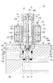
- FIG. 1 is a side sectional view of a motor operated valve according to a first embodiment of the present invention.
- Side sectional view of the motorized valve with the valve opening open Plan sectional view near the shaft support member
- Side sectional view of the vicinity of the valve body parts Cross-sectional side view near the rotor receiver
- Side sectional view of the vicinity of the rotor receiving portion according to the modified example Side sectional view of the vicinity of the rotor receiving portion according to the modified example
- Side sectional view of the vicinity of the rotor receiving portion according to the modified example Side sectional view of the vicinity of the rotor receiving portion according to the modified example.
- the motor-operated valve 10 includes a stator 11, a rotor 40 rotatably accommodated inside the stator 11, and a linear motion shaft that linearly moves in the stator 11 by the rotation of the rotor 40. 50.
- the stator 11 is formed by fixing a stator side field portion 13 on the outside of a sleeve 12 that extends vertically.
- the stator side field portion 13 has an annular shape and is provided with an electromagnetic coil 13A.
- the sleeve 12 includes an upper cylindrical portion 14 and a lower cylindrical portion 15 (corresponding to the “base portion” of the present invention), and the upper cylindrical portion 14 and the lower cylindrical portion 15 are arranged coaxially.
- the upper cylindrical portion 14 has a cylindrical shape with substantially the same diameter throughout, and the upper surface opening is sealed by the lid body 23.
- the stator side field portion 13 described above is fixed to the lower end portion of the upper cylindrical portion 14.
- the sleeve 12, the lid body 23 and the stator side field portion 13 constitute a “stator body” of the present invention.
- the lower cylinder portion 15 is located inside the valve body linear motion chamber 15X extending from the lower end portion to the intermediate portion, and above the valve body direct motion chamber 15X, and the valve body direct motion chamber.
- a rotor receiving portion 15Y having a diameter larger than 15X and an upper end receiving portion 15Z positioned above the rotor receiving portion 15Y and having a diameter larger than that of the rotor receiving portion 15Y are provided.
- the upper cylinder part 14 and the lower cylinder part 15 are connected by fitting the lower end part of the upper cylinder part 14 to the upper end receiving part 15Z.
- the lower end surface of the upper cylindrical portion 14 is abutted against an annular stepped portion 15D which is the inner surface of the upper end receiving portion 15Z, and a flange 15F projecting laterally from the upper end of the lower cylindrical portion 15 is a stator side field.
- the upper cylindrical portion 14 and the lower cylindrical portion 15 are welded while being in contact with the lower surface of the portion 13.
- a valve seat member 17 is fitted in the opening 16 on the lower end side of the lower cylindrical portion 15.
- the valve seat member 17 has a cylindrical shape, and an upper end opening thereof is a valve port 18. Further, the lower cylinder portion 15 is formed with a side opening 15 ⁇ / b> B opened laterally at a position near the lower end.
- the first flow path R1 is connected to the valve seat member 17, and the second flow path R2 is connected to the side opening 15B.
- the valve port 18 is opened and closed by a valve body 60 provided at the tip of the linear motion shaft 50.
- the valve body 60 has a truncated cone shape with a diameter reduced toward the tip, and enters the valve port 18 from above and contacts the valve seat 19 as shown in FIG. And regulate the flow. As shown in FIG. 2, the valve body 60 moves upward and opens the valve port 18, whereby the flow between the first flow path R ⁇ b> 1 and the second flow path R ⁇ b> 2 becomes possible.
- the linear motion shaft 50 having the valve body 60 is supported so as to be linearly movable and non-rotatable with respect to the lower cylindrical portion 15.
- the intermediate portion in the vertical direction of the linear motion shaft 50 is a sliding shaft portion 50 ⁇ / b> B having a D-shaped cross section, and the valve body of the lower cylinder portion 15.
- the shaft support member 25 is attached to the upper end of the linear motion chamber 15X.
- the shaft support member 25 has a substantially cylindrical shape and has a D-shaped shaft receiving hole 25D corresponding to the D-shaped cross section of the sliding shaft portion 50B, and restricts the rotation of the linear motion shaft 50. ing.
- the shaft support member 25 includes an upper member 25A and a lower member 25B.
- the upper member 25A has a smaller diameter than the lower member 25B and is received inside the lower member 25B.
- a flange 25F projecting laterally is provided at the upper end of the upper member 25A, and the lower surface of the flange 25F is in contact with the upper end of the lower member 25B.
- a protruding annular plate 25H that protrudes inward and faces the lower end surface of the upper member 25A is provided near the lower end of the lower member 25B.
- the shaft receiving hole 25D having a D-shaped cross section is formed in the upper member 25A.
- two communication holes 15 ⁇ / b> H are formed in the lower cylinder portion 15 around the receiving portion 15 ⁇ / b> G that receives the shaft support member 25, and the upper and lower portions separated by the shaft support member 25.
- the pressure in the space is almost uniform.
- the rotor 40 is formed by fixing a magnetic rotor side field portion 41 on the outer side of a cylindrical rotating screw tube 42.
- a stepping motor 20 corresponding to the “motor” of the present invention is configured with the rotor side field portion 41 and the stator side field portion 13 as main parts, and the excitation pattern of the electromagnetic coil 13A of the stator side field portion 13 is changed. As a result, the rotor-side field part 41 is controlled to be positioned at a predetermined rotational position.
- the rotor-side field magnet portion 41 is arranged from the position near the lower end of the rotating screw cylinder 42 to the upper side, and the lower end portion of the rotating screw cylinder 42 of the rotor 40 is disposed on the rotor receiving portion 15Y of the stator 11. Is accepted.
- the rotating screw cylinder 42 has a cylindrical shape with both ends open, and a female screw portion 42N is formed on the inner side near the lower end. Further, a male screw portion 50N is formed on the outer surface above the sliding shaft portion 50B of the linear movement shaft 50, and this male screw portion 50N is screwed into the female screw portion 42N of the rotary screwing cylinder 42. Yes.
- the rotor 40 rotates with respect to the stator 11 while being positioned in the axial direction by a positioning mechanism described later.
- the linear motion shaft 50 that is non-rotatably supported by the lower cylindrical portion 15 of the stator 11 is linearly moved by screwing with the rotary screwing tube 42, and the linear motion position of the valve body 60 is changed. .
- the motor-operated valve 10 is provided with the parts described below in order to regulate the amount of rotation of the rotor 40. That is, as shown in FIG. 1, the stator 11 is provided with a guide shaft 30 that hangs downward from the lid body 23. A spiral guide 31 is fixed to the guide shaft 30. The spiral guide 31 is formed by winding a wire rod around the guide shaft 30 in a spiral shape.
- the stopper ring 32 is engaged with the spiral guide 31.
- the stopper ring 32 has a ring shape that fits in a part of the gap between the wire rods adjacent in the axial direction in the spiral guide 31 and is provided with a stopper arm 32A protruding to the side.
- ring abutting portions 42S and 42S are arranged on the inner surface of the rotary screwing cylinder 42 of the rotor 40 so as to extend vertically above the female screw portion 42N and sandwich the stopper arm 32A. Only the ring contact portion 42S on the side is shown).
- the stopper ring 32 is pushed by the ring abutting portion 42S and rotates relative to the spiral guide 31 to move up and down and move to the upper end or lower end of the spiral guide 31. It becomes immobile. Thereby, the rotation amount of the rotor 40 is regulated.
- a pressing member 35 corresponding to the “intermediate member” of the present invention is provided between the lid 23 and the rotor 40 in the upper cylindrical portion 14 of the stator 11.
- the pressing member 35 includes an annular plate-shaped main plate portion 35A that bulges downward, and a support cylinder portion 35B that rises upward from its inner edge.
- the pressing member 35 is supported so as to be linearly movable and rotatable by inserting the guide shaft 30 into the supporting cylinder portion 35B. That is, in this embodiment, the guide shaft 30 that regulates the rotation amount of the rotor 40 is also used for supporting the pressing member 35.
- a tapered surface 35T is formed on the outer edge portion of the main plate portion 35A of the pressing member 35, and this tapered surface 35T comes into contact with the upper end opening edge 42A of the rotating screw cylinder 42 in the rotor 40.
- the upper end opening edge 42A is chamfered to form a small tapered surface.
- the spiral guide 31 of the guide shaft 30 is disposed below the pressing member 35.
- a compression coil spring 36 (corresponding to “rotor urging means” and “elastic member” of the present invention) is disposed between the pressing member 35 and the lid 23 so as to stretch.
- the pressing member 35 is urged downward by the compression coil spring 36 and presses the rotor 40 against the inner surface of the rotor receiving portion 15Y.
- the rotor 40 is positioned in the axial direction.
- the pressing member 35 and the compression coil spring 36 rotate with the rotation of the rotor 40, and the compression coil spring 36 is in sliding contact with the sliding contact plate 37 provided on the lid body 23.
- the pressing member 35 may be configured to be non-rotatable or difficult to rotate, and the rotor 40 may be configured to be in sliding contact with the pressing member 35.
- the inner surface of the rotor receiving portion 15 ⁇ / b> Y of the lower cylinder portion 15 is a tapered surface 15 ⁇ / b> T that is lowered toward the center.
- a tapered surface 42T that is tapered is formed also on the lower end surface of the rotary screwing cylinder 42 of the rotor 40, and when the rotor 40 is urged downward by the pressing member 35, the tapered surfaces 15T and 42T are brought together.
- the rotor 40 is centered with respect to the stator 11 while being in surface contact with each other.
- the tapered surface 15T of the lower cylinder portion 15 and the tapered surface 42T of the rotary threaded cylinder 42 have substantially the same inclination angle.
- the inclination angles of the tapered surfaces 15T and 42T are preferably angles (for example, 15 degrees or less) such that the rotary screwing cylinder 42 is not press-fitted into the inner portion of the rotor receiving portion 15Y.
- the upper opening edge 42A and the tapered surface 42T of the rotating screw cylinder 42 correspond to the “first contact portion” of the present invention, and the tapered surface 35T of the pressing member 35 and the taper of the lower cylinder portion 15 are provided.
- the surface 15T corresponds to the “second contact portion” of the present invention.
- a linear motion shaft 50 extends in the vertical direction, and a valve body component 55 including a valve body 60 is attached to a lower end portion of a shaft body 50A having a sliding shaft portion 50B and a male screw portion 50N. It becomes.
- a connecting hole 50D is drilled in the center of the lower end surface of the shaft main body 50A of the linear motion shaft 50, and the upper end of the valve body component 55 is accommodated in the connecting hole 50D. Has been.
- the valve body component 55 includes a valve body 60 and a retaining member 56 fixed to the upper end portion of the valve body 60 by, for example, press fitting, welding, or the like.
- the valve body 60 includes a truncated cone-shaped valve body body portion 60A tapered downward, a shaft portion 60B extending upward from the center of the upper surface of the valve body body portion 60A, and a lateral position from a position near the upper end of the valve body body portion 60A.
- a flange 60 ⁇ / b> F protruding to the surface. Note that the flange 60 ⁇ / b> F projects laterally from the linear motion shaft 50.
- the retaining member 56 has a bottomed cylindrical shape that receives the shaft portion 60B of the valve body 60, and a flange-shaped locking wall 56A is formed at the upper end. Then, the retaining ring 57 is press-fitted into the lower end portion of the connection hole 50D in a state where the flange-shaped locking wall 56A is inserted into the connection hole 50D, and the base end portion of the valve body component 55 is prevented from coming off in the connection hole 50D. . Further, since the connecting hole 50D is deeper than the entire length of the retaining member 56, the retaining member 56 can be moved directly within the connecting hole 50D. Thereby, the valve body 60 fixed to the retaining member 56 can be linearly moved with respect to the linear motion shaft 50. The retaining member 56, the coupling hole 50D, and the retaining ring 57 correspond to the “linear motion coupling mechanism” of the present invention.
- a compression coil spring 58 (shaft biasing means”, “valve biasing means” of the present invention, " Corresponding to “rotor urging means”.
- shaft biasing means "valve biasing means” of the present invention, " Corresponding to “rotor urging means”.
- the valve body 60 is urged
- the linear motion shaft 50 is also urged downward with respect to the stator 11, and the rotor 40 is also urged downward.
- the flange 60F of the valve body 60 corresponds to the “pressure receiving portion” of the present invention
- the protruding annular plate 25H of the shaft support member 25 corresponds to the “opposing portion” of the present invention.
- the configuration of the present embodiment is as described above. Next, the effect of this embodiment is demonstrated.
- the motor-operated valve 10 of this embodiment is incorporated in the body 100 (refer FIG. 1), for example.
- the linear motion shaft 50 having the valve body 60 is linearly moved by screwing with the rotary screwing cylinder 42 of the rotor 40, and the valve is opened.
- the flow rate of the refrigerant flowing between the first flow path R1 and the second flow path R2 is changed.
- the rotor 40 rotates while being pressed against the inner surface (tapered surface 15T) of the rotor receiving portion 15Y of the stator 11 by the pressing member 35 and the compression coil spring 36. 40 is prevented from shaking in the axial direction, and vibration noise can be reduced as compared with the conventional case.
- taper surfaces 15T and 42T are formed on the inner surface of the rotor receiving portion 15Y and the lower end surface of the rotary screwing cylinder 42 of the rotor 40, respectively, and the taper surfaces 15T and 42T are brought into surface contact with each other to form the rotor 40. Is centered with respect to the stator 11, so that the rotor 40 is prevented from rattling in the radial direction, and vibration noise is further reduced.
- the pressing member 35 is also formed with a tapered surface 35T, and this tapered surface 35T abuts against the tapered upper end opening edge 42A of the rotary screwing cylinder 42, so that the rotor 40 also against the stator 11 Centered.
- valve body 60 is connected to the linear motion shaft 50 so as to be linearly movable, it is possible to absorb an impact caused by contact between the valve body 60 and the opening edge of the valve port 18. At the same time, the contact pressure between the valve body 60 and the opening edge of the valve port 18 can be obtained by the compression coil spring 58.
- the linear motion shaft 50 is urged downward together with the valve body 60 by the compression coil spring 58 with respect to the rotor 40. It is possible to reduce the vibration sound due to the play. Moreover, since the rotor 40 is also urged
- the compression coil spring 58 that urges the valve body 60 is used for both the urging of the rotor 40 and the urging of the linear motion shaft 50, so that the number of parts can be reduced.
- the inner surface of the rotor receiving portion 15Y and the lower end surface of the rotary screwing cylinder 42 of the rotor 40 are both tapered surfaces, but as shown in FIG. There may be.
- the taper surface 15T of the rotor receiving portion 15Y and the taper surface 42T of the rotary threaded cylinder 42 of the rotor 40 are inclined so as to be lowered toward the center portion. Thus, it may be inclined so as to rise toward the center.
- the inner surface of the rotor receiving portion 15Y and the lower end surface of the rotary screwing cylinder 42 of the rotor 40 are in surface contact. It is good also as a structure by which line contact
- the “valve element urging means” of the present invention is configured to also serve as the “shaft urging means”, but may be configured to be provided separately.
- a compression coil spring as the “shaft urging means” of the present invention is inserted into the male screw portion 50N of the linear motion shaft 50, and the lower opening edge of the female screw portion 42N of the rotary screwing tube 42 In the linear motion shaft 50, a configuration in which it is accommodated in a compressed state between the stepped surface of the male screw portion 50N and the sliding shaft portion 50B can be cited.
- the “rotor urging means” of the present invention may be constituted only by the compression coil spring 58 or may be constituted only by the compression coil spring 36.
- the “rotor urging means” of the present invention is the compression coil springs 36, 58, but other elastic members (plate springs, rubbers, etc.) may be used.
- a configuration may be adopted in which a weight is applied to the rotor 40 and the rotor 40 is urged by the weight, or a magnet is attached so as to repel the rotor 40 and the lid body 23 of the stator 11, The structure which energizes may be sufficient.
- valve element urging means and the “shaft urging means” of the present invention are the compression coil springs 58, but other elastic members (plate springs, rubbers, etc.)
- the valve body 60 may be weighted and the linear movement shaft 50 may be biased by the weight, or the valve body 60 and the shaft support member 25 of the stator 11 may be repelled.
- biases the valve body 60 by those repulsive force may be sufficient.
- Motorized valve 11 Stator 15T Tapered surface (stator side sliding contact portion) 15Y Rotor receiving part 18 Valve port 20 Stepping motor (motor) 25 shaft support member 25D shaft receiving hole 30 guide shaft 31 spiral guide 32 stopper ring 35 pressing member (intermediate member) 35T Tapered surface (stator side sliding contact) 36 Compression coil spring (rotor biasing means) 40 rotor 42 rotating screw cylinder 42A upper end opening edge 42A (rotor side sliding contact portion) 42T taper surface (rotor side sliding contact) 50 linear motion shaft 55 valve body component 58 compression coil spring (valve body urging means, shaft urging means, rotor urging means) 60 Disc
Landscapes
- Engineering & Computer Science (AREA)
- General Engineering & Computer Science (AREA)
- Mechanical Engineering (AREA)
- Physics & Mathematics (AREA)
- Fluid Mechanics (AREA)
- Electrically Driven Valve-Operating Means (AREA)
Abstract
Description
以下、本発明の第1実施形態を図1~図5に基づいて説明する。図1に示すように、本実施形態の電動弁10は、ステータ11と、ステータ11の内側に回転可能に収容されたロータ40と、ロータ40の回転によりステータ11内を直動する直動シャフト50と、を備えている。
本発明は、前記実施形態に限定されるものではなく、例えば、以下に説明するような実施形態も本発明の技術的範囲に含まれ、さらに、下記以外にも要旨を逸脱しない範囲内で種々変更して実施することができる。
11 ステータ
15T テーパ面(ステータ側摺接部)
15Y ロータ受容部
18 弁口
20 ステッピングモータ(モータ)
25 シャフト支持部材
25D シャフト受容孔
30 ガイドシャフト
31 螺旋ガイド
32 ストッパリング
35 押付部材(中間部材)
35T テーパ面(ステータ側摺接部)
36 圧縮コイルバネ(ロータ付勢手段)
40 ロータ
42 回転螺合筒
42A 上端開口縁42A(ロータ側摺接部)
42T テーパ面(ロータ側摺接部)
50 直動シャフト
55 弁体部品
58 圧縮コイルバネ(弁体付勢手段、シャフト付勢手段、ロータ付勢手段)
60 弁体
Claims (8)
- モータと、
前記モータのステータの一端に設けられたベース部と、
前記モータのロータに螺合しかつ前記ベース部に直動可能かつ回転不能に支持されている直動シャフトと、
前記ベース部に形成されている弁口と、
前記直動シャフトの一端に設けられ、前記弁口を開閉する弁体と、
前記ロータと前記ステータとの間に配された中間部材又は前記ステータと、前記ロータと、にそれぞれ設けられて、前記ロータの回転軸方向で互いに当接する、前記ロータ側の第1当接部及び前記ステータ側又は前記中間部材側の第2当接部と、
前記第1当接部及び前記第2当接部が互いに押し付けられるように前記ロータを回転軸方向に付勢するロータ付勢手段とを備える電動弁。 - 前記第1当接部は、前記ロータの両端部に設けられ、
前記第2当接部は、前記ロータを回転軸方向で挟む2位置に設けられると共に、それら2位置のうちの少なくとも一方の前記第2当接部が、前記ステータの本体に対して直動可能な前記中間部材に設けられ、
前記中間部材と前記ステータの本体との間には、前記ロータ付勢手段としての弾性部材が設けられている請求項1に記載の電動弁。 - 前記ステータの本体に取り付けられ、かつ、前記直動シャフトと同軸上に延びたガイドシャフトと、
前記ガイドシャフトの外面に設けられた螺旋ガイドと、
前記ガイドシャフトに取り付けられ、前記ロータの回転に応じて前記螺旋ガイドの上端から下端まで移動して前記ロータの回転量を規制するストッパリングと、を備え、
前記中間部材は前記ガイドシャフトに支持されている請求項2に記載の電動弁。 - 前記第1当接部及び前記第2当接部の一方又は両方に、前記ロータを前記ステータに対して芯出しするテーパ面が形成されている請求項1乃至3の何れか1の請求項に記載の電動弁。
- 前記直動シャフトを前記ロータに対して直動方向の一方に付勢するシャフト付勢手段を備える請求項1乃至4の何れか1の請求項に記載の電動弁。
- 前記弁口は、前記弁体を挟んで前記直動シャフトの反対側に配置され、
前記弁体を、前記直動シャフトの一端部に直動可能かつ離脱不能に連結する直動連結機構と、
前記弁体を前記直動シャフトに対して前記弁口に向けて付勢する弁体付勢手段とを備える請求項1乃至5の何れか1の請求項に記載の電動弁。 - 前記弁体付勢手段が前記ロータ付勢手段を兼ねている請求項6に記載の電動弁。
- 前記弁体に形成されて、前記直動シャフトより側方に張り出す受圧部と、
前記ベース部に形成されて、前記受圧部に前記弁口の反対側から対向する対向部と、
前記受圧部と前記対向部との間で圧縮状態になっている前記弁体付勢手段としての圧縮コイルバネとを備える請求項6又は7に記載の電動弁。
Priority Applications (5)
| Application Number | Priority Date | Filing Date | Title |
|---|---|---|---|
| CN201680002819.9A CN107076329B (zh) | 2016-06-23 | 2016-06-23 | 电动阀 |
| DE112016002578.5T DE112016002578B4 (de) | 2016-06-23 | 2016-06-23 | Motorbetätigtes Ventil |
| US15/510,733 US10253903B2 (en) | 2016-06-23 | 2016-06-23 | Motor-operated valve |
| JP2016565714A JP6542806B2 (ja) | 2016-06-23 | 2016-06-23 | 電動弁 |
| PCT/JP2016/068644 WO2017221370A1 (ja) | 2016-06-23 | 2016-06-23 | 電動弁 |
Applications Claiming Priority (1)
| Application Number | Priority Date | Filing Date | Title |
|---|---|---|---|
| PCT/JP2016/068644 WO2017221370A1 (ja) | 2016-06-23 | 2016-06-23 | 電動弁 |
Publications (1)
| Publication Number | Publication Date |
|---|---|
| WO2017221370A1 true WO2017221370A1 (ja) | 2017-12-28 |
Family
ID=59623888
Family Applications (1)
| Application Number | Title | Priority Date | Filing Date |
|---|---|---|---|
| PCT/JP2016/068644 Ceased WO2017221370A1 (ja) | 2016-06-23 | 2016-06-23 | 電動弁 |
Country Status (5)
| Country | Link |
|---|---|
| US (1) | US10253903B2 (ja) |
| JP (1) | JP6542806B2 (ja) |
| CN (1) | CN107076329B (ja) |
| DE (1) | DE112016002578B4 (ja) |
| WO (1) | WO2017221370A1 (ja) |
Families Citing this family (11)
| Publication number | Priority date | Publication date | Assignee | Title |
|---|---|---|---|---|
| CN107327435A (zh) * | 2017-08-21 | 2017-11-07 | 泸州精通流体液压机械有限公司 | 一种通过电控系统控制液压阀换向的方法 |
| US20190063614A1 (en) * | 2017-08-23 | 2019-02-28 | Tangtring Seating Technology Inc. | Screw valve having enhanced airtight effect |
| US11903749B2 (en) * | 2017-10-19 | 2024-02-20 | Spectrum Dynamics Medical Limited | Nuclear medicine tomography system comprising a detector carrier housing and a heat pump configured to cool air within the detector carrier housing |
| EP3698326A4 (en) | 2017-10-19 | 2021-08-11 | Spectrum Dynamics Medical Limited | CALIBRATION AND QUALITY CONTROL OF A RADIO IMAGING SYSTEM FOR NUCLEAR MEDICINE (N-M) |
| EP3698176B1 (en) * | 2017-10-19 | 2023-10-11 | Spectrum Dynamics Medical Limited | Moving parts in a nuclear medicine (n-m) imaging system |
| LU100576B1 (en) * | 2017-12-15 | 2019-06-28 | Luxembourg Patent Co | Electromagnetic sleeve for hydrogen valve |
| CN113154114A (zh) * | 2018-06-15 | 2021-07-23 | 杭州三花研究院有限公司 | 电动阀 |
| WO2020189736A1 (ja) * | 2019-03-20 | 2020-09-24 | 株式会社不二工機 | 電動弁 |
| JP7025563B2 (ja) * | 2019-03-27 | 2022-02-24 | 太平洋工業株式会社 | モータ駆動弁 |
| JP7555594B2 (ja) * | 2021-09-15 | 2024-09-25 | 株式会社不二工機 | 電動弁 |
| CN120845537B (zh) * | 2025-09-22 | 2025-11-28 | 温州美瑞克液压科技有限公司 | 一种具有阀杆缓冲功能的比例电磁阀 |
Citations (2)
| Publication number | Priority date | Publication date | Assignee | Title |
|---|---|---|---|---|
| JP2006307964A (ja) * | 2005-04-28 | 2006-11-09 | Furukawa Electric Co Ltd:The | 電動制御弁 |
| JP2016089870A (ja) * | 2014-10-30 | 2016-05-23 | 株式会社鷺宮製作所 | 電動弁 |
Family Cites Families (14)
| Publication number | Priority date | Publication date | Assignee | Title |
|---|---|---|---|---|
| JP3328530B2 (ja) * | 1996-12-12 | 2002-09-24 | 太平洋工業株式会社 | 電動弁のストッパー構造 |
| JP3905602B2 (ja) | 1997-07-03 | 2007-04-18 | 株式会社不二工機 | 電動弁 |
| JPH1162848A (ja) | 1997-08-07 | 1999-03-05 | Denso Corp | ブレーキ液圧制御装置用アクチュエータ |
| US6492751B1 (en) * | 1999-01-29 | 2002-12-10 | Siemens Vdo Automotive Corporation | Magnetic device with spaced apart pole plates, flux return strip and electrical connector having integral mounting |
| JP3937029B2 (ja) * | 1999-03-26 | 2007-06-27 | 株式会社鷺宮製作所 | 電動弁 |
| JP3886084B2 (ja) | 1999-04-01 | 2007-02-28 | 日本電産サンキョー株式会社 | 流量制御装置 |
| JP4228836B2 (ja) | 2003-08-20 | 2009-02-25 | ダイキン工業株式会社 | 冷凍装置用電動膨張弁 |
| JP2006010004A (ja) * | 2004-06-28 | 2006-01-12 | Saginomiya Seisakusho Inc | 電動式コントロールバルブ |
| JP4550528B2 (ja) * | 2004-09-01 | 2010-09-22 | 株式会社不二工機 | 電動弁 |
| JP5740586B2 (ja) * | 2010-11-18 | 2015-06-24 | 株式会社テージーケー | ステッピングモータ駆動式の制御弁 |
| US9726406B2 (en) * | 2012-02-10 | 2017-08-08 | Kabushiki Kaisha Saginomiya Seisakusho | Expansion valve |
| JP5996455B2 (ja) | 2013-02-27 | 2016-09-21 | ジョンソンコントロールズ ヒタチ エア コンディショニング テクノロジー(ホンコン)リミテッド | スクロール圧縮機 |
| US9657656B2 (en) * | 2014-08-27 | 2017-05-23 | Continental Automotive Systems, Inc. | Idle air control valve for use in a small engine and having a protective shroud with valve seat |
| JP2016065595A (ja) * | 2014-09-25 | 2016-04-28 | 太平洋工業株式会社 | モータ駆動弁 |
-
2016
- 2016-06-23 CN CN201680002819.9A patent/CN107076329B/zh active Active
- 2016-06-23 JP JP2016565714A patent/JP6542806B2/ja active Active
- 2016-06-23 WO PCT/JP2016/068644 patent/WO2017221370A1/ja not_active Ceased
- 2016-06-23 US US15/510,733 patent/US10253903B2/en active Active
- 2016-06-23 DE DE112016002578.5T patent/DE112016002578B4/de active Active
Patent Citations (2)
| Publication number | Priority date | Publication date | Assignee | Title |
|---|---|---|---|---|
| JP2006307964A (ja) * | 2005-04-28 | 2006-11-09 | Furukawa Electric Co Ltd:The | 電動制御弁 |
| JP2016089870A (ja) * | 2014-10-30 | 2016-05-23 | 株式会社鷺宮製作所 | 電動弁 |
Also Published As
| Publication number | Publication date |
|---|---|
| CN107076329A (zh) | 2017-08-18 |
| US20170370499A1 (en) | 2017-12-28 |
| JP6542806B2 (ja) | 2019-07-10 |
| JPWO2017221370A1 (ja) | 2018-10-04 |
| DE112016002578T5 (de) | 2018-05-24 |
| CN107076329B (zh) | 2019-04-23 |
| DE112016002578B4 (de) | 2025-07-17 |
| US10253903B2 (en) | 2019-04-09 |
Similar Documents
| Publication | Publication Date | Title |
|---|---|---|
| WO2017221370A1 (ja) | 電動弁 | |
| JP6392685B2 (ja) | 電動弁 | |
| JP6270650B2 (ja) | 電動弁 | |
| KR102445410B1 (ko) | 전자 팽창 밸브 | |
| JP6580125B2 (ja) | 電動弁 | |
| JP5535580B2 (ja) | 自動開閉扉蝶番 | |
| KR102498207B1 (ko) | 전자 팽창 밸브 및 상기 전자 팽창 밸브를 사용한 공조 시스템 | |
| JP2016023709A (ja) | 電動弁 | |
| JP5436686B2 (ja) | 電子膨張弁 | |
| JP2013539850A (ja) | 電動弁 | |
| WO2017168942A1 (ja) | 電動弁 | |
| JP6228621B2 (ja) | 電動弁 | |
| KR100938132B1 (ko) | 도어클로저 어셈블리 | |
| CN106839619A (zh) | 冰箱的门体组件及冰箱 | |
| CN105937632B (zh) | 电动阀 | |
| JP5389498B2 (ja) | 電動弁 | |
| CN110296258B (zh) | 电子膨胀阀 | |
| WO2021004332A1 (zh) | 动涡盘驱动组件和涡旋式压缩机 | |
| JP2007270955A (ja) | ロータリーダンパーの破壊防止機構 | |
| JP2016065595A (ja) | モータ駆動弁 | |
| JP2004108110A (ja) | ストッパー機能付き蝶番 | |
| JP4680658B2 (ja) | 電動弁 | |
| WO2020132967A1 (zh) | 电子膨胀阀 | |
| JP6909436B2 (ja) | モータ及びモータユニット | |
| JP2017223372A (ja) | 電動弁 |
Legal Events
| Date | Code | Title | Description |
|---|---|---|---|
| ENP | Entry into the national phase |
Ref document number: 2016565714 Country of ref document: JP Kind code of ref document: A |
|
| WWE | Wipo information: entry into national phase |
Ref document number: 112016002578 Country of ref document: DE |
|
| WWE | Wipo information: entry into national phase |
Ref document number: 15510733 Country of ref document: US |
|
| 121 | Ep: the epo has been informed by wipo that ep was designated in this application |
Ref document number: 16906287 Country of ref document: EP Kind code of ref document: A1 |
|
| 122 | Ep: pct application non-entry in european phase |
Ref document number: 16906287 Country of ref document: EP Kind code of ref document: A1 |
|
| WWG | Wipo information: grant in national office |
Ref document number: 112016002578 Country of ref document: DE |