WO2017217458A1 - 液体収納容器の抜き取り装置および液体収納容器の抜き取り方法 - Google Patents
液体収納容器の抜き取り装置および液体収納容器の抜き取り方法 Download PDFInfo
- Publication number
- WO2017217458A1 WO2017217458A1 PCT/JP2017/021981 JP2017021981W WO2017217458A1 WO 2017217458 A1 WO2017217458 A1 WO 2017217458A1 JP 2017021981 W JP2017021981 W JP 2017021981W WO 2017217458 A1 WO2017217458 A1 WO 2017217458A1
- Authority
- WO
- WIPO (PCT)
- Prior art keywords
- container
- liquid storage
- outer container
- liquid
- main body
- Prior art date
- Legal status (The legal status is an assumption and is not a legal conclusion. Google has not performed a legal analysis and makes no representation as to the accuracy of the status listed.)
- Ceased
Links
Images















Classifications
-
- B—PERFORMING OPERATIONS; TRANSPORTING
- B65—CONVEYING; PACKING; STORING; HANDLING THIN OR FILAMENTARY MATERIAL
- B65B—MACHINES, APPARATUS OR DEVICES FOR, OR METHODS OF, PACKAGING ARTICLES OR MATERIALS; UNPACKING
- B65B69/00—Unpacking of articles or materials, not otherwise provided for
Definitions
- This embodiment is for extracting a liquid storage container used by being stored and used in an outer container used for storage and transportation of fluid contents, particularly in the industrial chemical field, pharmaceutical and cosmetic raw material fields, etc.
- the present invention relates to a liquid storage container extraction device and a liquid storage container extraction method.
- liquid storage containers that are placed inside exterior containers made of aluminum, steel, stainless steel, fiberboard, etc. for storage and transportation and contain fluid contents in use.
- Such a liquid storage container can be reused by simply removing a used liquid storage container from the outer container and setting a new liquid storage container in the outer container. Compared to filling fluid contents in steel or other external containers directly, it has the advantage of eliminating the hassle of washing, etc., and is widely used as a container for industrial chemicals, pharmaceuticals and cosmetic raw materials .
- a liquid storage container having a bag body and a spout attached to the bag body is known.
- the spout has a spout attachment part heat-sealed to the bag body, and a spout body protruding from the spout attachment part to the outside of the bag body.
- Such a liquid storage container is first folded compactly and inserted into the exterior container from the opening of the exterior container.
- nitrogen gas is supplied into the liquid storage container to inflate the liquid storage container inside the outer container.
- the liquid container is filled with the content liquid.
- the exterior container has a trunk portion, a bottom portion, and a top plate that are integrally formed, and has a volume of 200 L or more.
- the opening is provided in the top plate, and the bag main body of the liquid storage container is stored in the outer container through the opening, and the bag main body is pulled out from the outer container through the opening. Since the outer container has a volume of 200 L or more, it is not easy to extract the bag body from the large outer container.
- the present embodiment has been made in consideration of such points, and a liquid storage container extraction device and a liquid storage container extraction that can easily extract a bag body from a large exterior container through an opening. It aims to provide a method.
- the present embodiment is arranged in an exterior container having an opening, has a spout and a bag body, and opens the bag body of a liquid storage container whose width of the bag body is larger than the inner diameter of the opening.
- a liquid storage container extraction device that extracts the exterior container through a portion
- a fixing device that fixes one of the exterior container and the liquid storage container
- a liquid storage container extraction device comprising: a pulling device that pulls the other side and relatively separates the outer container and the liquid storage container.
- This embodiment may be a liquid storage container extraction device in which the separation device relatively separates the outer container and the liquid storage container in the vertical direction.
- This embodiment may be a liquid storage container extraction device in which the separation device relatively separates the outer container and the liquid storage container in the horizontal direction.
- the fixing device fixes the outer container and has an abutting portion that comes into contact with the outer container, and the abutting portion is a resin container extraction device made of resin. May be.
- the present embodiment may be a liquid storage container extraction device that further includes a device main body that stores at least one of the fixing device and the separation device.
- the present embodiment may be a liquid storage container extraction device in which a cover plate that covers the exterior container and the liquid storage container is attached to the apparatus main body.
- This embodiment may be a liquid storage container extraction device in which the outer container has a volume of 200 L or more.
- the separating device may be a liquid container extracting device that pulls the liquid container, and the separating device includes a rotation mechanism that rotates the liquid container.
- the present embodiment may be a liquid storage container extraction device in which the separation device is movable along a direction orthogonal to a separation direction connecting the fixing device and the separation device.
- the present embodiment is an apparatus for extracting a liquid storage container, further comprising a transport mechanism that is provided in a direction orthogonal to a pulling direction connecting the pulling device and the fixing device, and transports the outer container. Also good.
- the present embodiment is arranged in an exterior container having an opening, has a spout and a bag body, and opens the bag body of a liquid storage container whose width of the bag body is larger than the inner diameter of the opening.
- the exterior device includes a step of fixing one of the exterior container and the liquid storage container to a fixing device, and a separation device. And pulling the other of the container and the liquid storage container to relatively separate the outer container and the liquid storage container.
- the bag body of the liquid storage container can be easily extracted from the large exterior container through the opening.
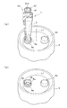
- FIG. 1 is a plan view showing a liquid storage container according to a first embodiment of a liquid storage container extraction apparatus.
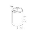
- 2A and 2B are views showing a state in which the liquid storage container is inserted into the outer container.
- FIG. 3 is a side view showing the spout attached to the bag body.
- FIG. 4 is a diagram showing an inflating action.
- FIG. 5 is a perspective view showing a spout.
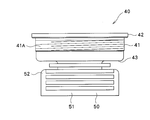
- FIG. 6 is a side view showing the spout.
- FIG. 7 is a side view of the spout viewed from a direction different from that of FIG. 6 by 90 °.
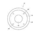
- FIG. 8 is a top view showing the spout.
- FIG. 9 is a bottom view showing the spout.
- FIG. 1 is a plan view showing a liquid storage container according to a first embodiment of a liquid storage container extraction apparatus.
- 2A and 2B are views showing a state in which the liquid storage container is inserted into the outer container
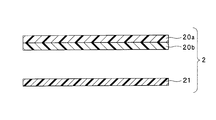
- FIG. 10 is a cross-sectional view showing the layer structure of the bag body of the liquid storage container.
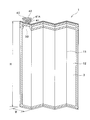
- 11A is a view showing the folded liquid storage container
- FIG. 11B is an enlarged view of a portion B in FIG. 11A
- FIG. 11C is an enlarged view of a portion C in FIG. 11A.
- FIG. 12 is a view showing a state in which the bag body of the liquid storage container is folded in a belly shape through a vertical folding line.
- FIG. 13 is a diagram illustrating a state in which the bag body of the liquid storage container is folded through an upper lateral fold curve and a lower lateral fold curve.
- FIG. 14 is a view showing a triangular bent portion formed by folding a bag body of a liquid storage container through a folding line.
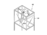
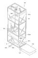
- FIG. 15 is an external view showing a liquid container extracting device.
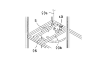
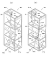
- FIG. 16A is a diagram showing a sampling device without an outer container
- FIG. 16B is a diagram showing a sampling device containing the outer container
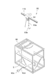
- FIG. 16C is a diagram showing a fixing device having a resin part.
- FIG. 17 is a view showing a method of extracting the outer container.
- FIG. 18 is a view showing a method of extracting the outer container.
- FIG. 19 is a view showing a method of extracting the outer container.
- FIG. 20 is a view showing a method of extracting the outer container.
- FIG. 21 is a view showing a method of extracting the outer container.
- FIG. 22 is a view showing a method of extracting the outer container.
- FIG. 23 is a view showing a modification of the exterior container extraction device.
- FIG. 24 is a view showing a modification of the exterior container extraction device.
- FIG. 25 is a view showing a modification of the exterior container extraction device.
- FIG. 26 is a view showing a modification of the exterior container extraction device.
- FIG. 27 is a view showing a modification of the exterior container extraction device.
- FIG. 28 is a view showing a modification of the exterior container extraction device.
- FIGS. 29A and 29B are views showing a second embodiment of the liquid container extracting device.
- FIGS. 30A and 30B are views showing a third embodiment of a liquid container extracting device.
- 31 (a) and 31 (b) are views showing a fourth embodiment of a liquid container extracting device.
- FIG. 32 is a diagram showing a fifth embodiment of the liquid container extracting device.
- FIG. 33 is a diagram showing a sixth embodiment of a liquid container extracting device.
- FIG. 34 is an external view showing a seventh embodiment of the liquid container extracting device.
- FIG. 35 is an external view showing an eighth embodiment of a liquid container extracting device.
- FIG. 36 is an enlarged view of a main part showing a ninth embodiment of a liquid container extracting device.
- FIG. 37 is a plan view showing a tenth embodiment of a liquid container extracting device.
- FIG. 1 to FIG. 28 are diagrams showing a first embodiment of the present invention.
- FIG. 1 is a plan view showing the liquid storage container
- FIGS. 2A and 2B are views showing a combination of the exterior container and the liquid storage container
- FIG. 3 is a combination of the exterior container and the liquid storage container
- FIG. 4 is a side sectional view showing the body
- FIG. 4 is a view showing an inflating action.
- the combination of the outer container and the liquid storage container includes a synthetic resin outer container 5 having an opening 5a provided at a position shifted (disengaged) from the first central portion L1 passing through the central portion of the top plate, and the outer packaging. And a liquid storage container 1 disposed in the container 5.
- a bag body 3 to be described later is inserted from the opening 5 a of the outer container 5.
- the opening part 5A other than the opening part 5a is provided in the top plate of the exterior container 5 (refer Fig.2 (a) (b)).
- the liquid storage container 1 is not inserted into the opening 5A in the present embodiment, but the opening 5A is inserted into the exterior container 5 and fixed to the opening 5a. It can be used as a visual hole for confirming the state of the liquid container 1 in the outer container 5.
- the outer container 5 has a capacity of, for example, 200 L or more, a diameter of 585 mm, and a height of 880 mm, and both the opening 5a and the opening 5A have a diameter of 80 mm.
- a steel drum can be used as the outer container 5, and the steel drum has a capacity of, for example, 200 L or more, a diameter of 580 mm, a height of 890 mm, and the opening 5 a has a diameter of 72 mm.
- 5A has a diameter of 32 mm.
- the liquid storage container 1 has a rectangular bag body 3 and a spout 40 provided at a position shifted (disengaged) from the second center portion L2 passing through the center portion of the upper edge 3a of the bag body 3.
- the spout 40 is mounted in the opening 5 a of the outer container 5.
- liquid container 1 Next, the liquid container 1 will be further described.
- the liquid storage container 1 includes a multi-layer film 2 in which an outer bag 20 and an inner bag 21 are overlapped so that the inner bags 21 face each other to form a total of four sheets. 10 is formed, and the spout 40 is disposed on the upper edge 3a of the bag body 3 and heat-sealed between the inner bags 21 in advance.
- the bag body 3 is obtained by laminating the multiple films 2 so that the inner bags 21 face each other and heat-sealing four sides to form the heat-sealed portion 10.
- the multiple films 2 may be formed by folding the multiple film 2 so that the inner bags 21 face each other, and then heat-sealing the three outer peripheral sides that overlap each other.
- each part of the inner edge of the heat seal part 10 may be formed so that the inner edge is arcuate. As a result, a structure in which the fluid content hardly remains at the corners is obtained.
- the bag body does not necessarily need to be composed of multiple films, and the film structure of the package body 3 can be selected as appropriate according to the contents and quantity.
- the bag body 3 can be obtained by stacking the two multiple films 2 and heat-sealing the periphery to form the heat seal portion 10.
- the bag body 3 has a rectangular shape having an upper edge 3a, a bottom edge 3b, and two side edges 3c, 3c.
- the upper edge 3a includes two upper edge heat seal portions 10a
- the bottom edge 3b includes one bottom edge heat seal portion 10b
- each side edge 3c, 3c includes one side edge heat seal portion 10c.
- the upper edge heat seal portion 10a, the bottom edge heat seal portion 10b, and the side edge heat seal portion 10c constitute the heat seal portion 10.
- the upper edge 3a of the bag body 3 includes the two upper edge heat seal portions 10a as described above. In this way, by dividing the heat seal portion 10a of the upper edge 3a into two, for example, compared to a case where one heat seal portion having a width of two heat seal portions 10a is formed on the upper edge 3a, The upper edge 3a can be configured to be relatively soft. Further, the upper edge heat seal portion 10a is not limited to two, and may be one or three or more.
- the multiple film 2 is not limited to a two-layer structure in which the outer bag 20 and the inner bag 21 are overlapped, and one or more inner bags 22 are further formed.
- a three-layer structure may be used, or a single-layer structure including only the inner bag 21 or the outer bag 20 may be used.
- the spout 40 includes a spout attachment part 50 that is heat-sealed to the upper edge 3a of the bag body 3 and a spout body 41 that is connected to the spout attachment part 50 and protrudes outward from the bag body 3.
- a spout flange 42 is provided at the upper end of the spout main body 41. Further, as shown in FIG. 1, the spout 40 is heat-sealed between the inner bags 21 of the multiplex film 2 at the spout attachment portion 50.
- the spout attachment portion 50 of the spout 40 is an elliptic cylinder having a central portion 51 and thin portions 52 provided on both sides of the central portion 51 and having a thickness thinner than the thickness of the central portion 51.
- the body is flat and has a through hole 45 in the central portion 51.
- the spout main body 41 of the spout 40 is formed of a cylindrical body having a substantially U-shaped cross section, and a spout flange 42 is provided on the peripheral edge of the top end.
- An opening 44 is formed in the bottom 43 of the spout main body 41. After the spout 40 is attached to the outer container 5, the opening 44 can ensure ventilation of the outside of the outer container 5 and the space between the liquid storage container 1 and the outer container 5.
- gas is sealed between the liquid storage container 1 and the outer container 5 through the opening 44, and pressure is applied from the outside of the liquid storage container 1 to transfer the content liquid inside the liquid storage container 1. The pumping can be performed smoothly.
- the spout main body 41 of the spout 40 is provided with an external screw 41A, and the opening 5a of the outer container 5 is provided with an internal screw 5B that engages with the external screw 41A. Yes. Then, by screwing the outer screw 41A of the spout 40 into the inner screw 5B of the opening 5a, the spout 40 can be reliably fixed in the opening 5a. In this case, the spout flange 42 of the spout 40 is attached to the opening 5 a formed in the outer container 5, and the liquid storage container 1 is supported in the outer container 5.
- a fixing means is constituted by the outer screw 41A of the spout 40 and the inner screw 5B of the opening 5a.
- the spout 40 is preferably manufactured by an injection molding method.
- the resin used for this is not particularly limited as long as it is a resin that can be injection-molded.
- the resin constituting the inner surface of the inner bag 21 of the multiplex film 2 is bonded by thermal fusion, although it is necessary to select appropriately depending on the resin constituting the inner surface, high-density polyethylene that is rigid at high temperatures and hardly brittle at low temperatures is preferable.
- the multiplex film 2 constituting the bag body 3 will be described.
- the multiple film 2 is composed of a film constituting the outer bag 20 and a film constituting the inner bag 21.
- a laminate of unstretched nylon (thickness 20 ⁇ m) 20 a / linear low density polyethylene (thickness 40 ⁇ m) 20 b can be used as the outer bag 20 of the bag body 3.
- linear low density polyethylene (thickness 70 ⁇ m) can be used.
- the outer bag 20 contains unstretched nylon 20a, the degree of elongation of the outer bag 20 can be increased.
- the outer bag 20 has a degree of elongation of 300% to 500%.
- the bag body 3 can be made soft as a whole, and the bag body 3 is inserted into the outer container 5 as will be described later.
- the bag body 3 is inflated in the outer container by supplying nitrogen gas or clean dry air into the inside, the bag body 3 can be smoothly inflated.
- the material of the bag body 3 is not limited to the above.
- materials such as low density polyethylene, low density polyethylene, and linear low density polyethylene can be used.
- materials having an elongation of 300% to 500% such as low density polyethylene and linear low density polyethylene, can be used.
- the abdomen 12 is formed by folding the bag body 3 of the liquid storage container 1 along the vertical folding line 11 (FIG. 12).
- the folded portion 16 is formed by folding the bag body 3 formed with the abdomen 12 via the upper lateral fold line 15a and the lower lateral fold line 15b (FIG. 13).
- the bag body 3 is bent along the folding line 13 to form a triangular bent portion 14 (FIG. 14).
- the liquid storage container 1 is prepared in which the bag body 3, the belly portion 12, the folding portion 16, and the triangular folding portion 14 are formed. Is done. Note that either the step of forming the belly portion 12 or the step of forming the folding portion 16 may be performed first.
- FIGS. 11 (a), (b), and (c) show that the belly portion 12 is formed first. This embodiment is illustrated.
- the folding portion 16 is omitted in FIG. 12, and the abdominal portion 12 is omitted in FIG.
- the liquid storage container 1 is folded and formed in an elongated shape in the vertical direction, and the liquid storage container 1 is inserted into the exterior container 5 from the opening 5a. .
- the spout 40 of the liquid storage container 1 is attached to the opening 5 a of the outer container 5.
- the spout 40 is first rotated with respect to the opening 5a.
- the outer screw 41A of the spout 40 is screwed into the inner screw 5B of the opening 5a, and the outer screw 41A of the spout 40 is engaged with the inner screw 5B of the opening 5a.
- the spout flange 42 of the spout main body 41 of the spout 40 abuts against the opening 5a of the outer container 5 and the rotation of the spout 40 stops.
- the spout 40 can be firmly fixed to the opening 5a.
- a spout 40 of the liquid storage container 1 described later is attached to the opening 5 a of the outer container 5, and the bag body 3 of the liquid storage container 1 is gently flattened inside the outer container 5.
- the width direction of the spout attachment portion 50 is parallel to a straight line L3 connecting the first central portion L1 of the outer container 5 and the opening 5a, and the first of the opening 5a of the outer container 5 is expanded.
- the displacement direction from the center portion L1 (left direction in FIG. 4A) is the same as the displacement direction from the second center portion L2 of the spout 40 of the liquid storage container 1 (left direction in FIG. 4A).
- An inner screw 5A and an outer screw 41A are provided so as to face.
- the width direction of the spout mounting portion 50 refers to a direction parallel to the flat direction of the spout mounting portion 50 that extends in a flat shape and is orthogonal to the through hole 45.
- the straight line L3 connecting the first central portion L1 of the outer container 5 and the opening 5a indicates a perpendicular when a perpendicular is drawn from the opening 5a to the first central portion L1.
- the perpendicular does not necessarily pass through the center when viewed from above the opening 5a, and the perpendicular passes through the edge when viewed from above the opening 5a.
- the term “parallel” includes not only a state where two lines are straight lines in a geometrical sense but also a state where two lines are curved lines.
- the angle in the state in which the two lines form an angle indicates a state of 20 degrees or less.
- the angle is preferably 10 degrees or less, and more preferably the angle is 5 degrees or less.
- the “same direction” includes not only the state in which the two directions exactly match but also the state in which the two directions form an angle, and the angle formed by the two directions is 20 A state of less than or equal to degrees, preferably an angle of 10 degrees or less, more preferably an angle of 5 degrees or less.
- an expansion jig (not shown) is attached to the spout 40 of the liquid storage container 1, and nitrogen gas or clean dry air is supplied into the liquid storage container 1 using the expansion jig, and the outer container 5.
- nitrogen gas or clean dry air is supplied into the liquid storage container 1 using the expansion jig, and the outer container 5.
- the bag body 3 of the liquid container 1 swells.
- the bag body 3 is inflated by supplying nitrogen gas or clean dry air into the liquid storage container 1 using an inflating jig. At this time, the bag body 3 that gently spreads in a flat shape swells three-dimensionally in a direction perpendicular to its surface.
- the triangular bent part 14 formed by bending through the folding line 13 is formed in the upper part of the bag body 3, the upper edge 3a of the bag body 3 is expanded when the bag body 3 expands. The corner is not caught by the opening 5a of the outer container 5, the bag body 3 can be sufficiently expanded in the outer container 5, and the bag body 3 can be prevented from being damaged.
- the upper edge 3a of the bag body 3 includes the two upper edge heat seal portions 10a, the upper edge 3a can be configured to be softer than the case of including a wide heat seal portion, and the bag body 3 can be made more flexible. It can be smoothly expanded in the outer container 5. Furthermore, since the outer bag 20 of the bag body 3 has an elongation of 300% to 500%, the flexibility of the bag body 3 can be enhanced and the expansion action of the bag body 3 can be easily performed.
- the bag body 3 of the liquid storage container 1 is gently flattened inside the outer container 5 as described above. To spread.
- the width direction of the spout attachment portion 50 is parallel to a straight line L3 connecting the first central portion L1 of the outer container 5 and the opening 5a, and from the first central portion L1 of the opening 5a of the outer container 5.
- the shift direction faces the same direction as the shift direction of the spout 40 from the second central portion L2. For this reason, even if the opening 5a is deviated from the first central portion L1 of the outer container 5 and the spout 40 is deviated from the second central portion L2 of the liquid storage container 1, it is in the bag body 3 of the liquid storage container 1.
- the bag body 3 of the liquid storage container 1 can be reliably inflated in the outer container 5 (see FIG. 4).
- the width direction of the spout attachment portion 50 is parallel to the straight line L3 connecting the first central portion L1 of the outer container 5 and the opening 5a
- the width direction of the bag body 3 of the liquid storage container 1 is the outer container. It faces the same direction as the diameter direction of 5.
- the bag body 3 is inflated in the outer container 5
- the bag body 3 swells in the direction perpendicular to the surface of the bag body 3, so that the width direction of the spout attachment portion 50 faces the same direction as the diameter direction of the outer container 5.
- the bag main body 3 of the liquid storage container 1 has the largest room for swelling in the outer container 5.
- the bag body 3 of the liquid storage container 1 when the bag body 3 of the liquid storage container 1 is inflated, the bag body 3 is prevented from being caught on the inner wall of the outer container 5, bent at the inner wall, and part of the bag body 3 being blocked. It is possible to secure a sufficient internal volume of the bag body 3.
- the inflating jig is removed from the spout 40, and a content liquid filling machine (not shown) is attached to the spout 40, and the content liquid is filled into the liquid storage container 1 from the content liquid filling machine.
- the liquid distribution nozzle 60 is held in the spout body 41 of the spout 40 attached to the opening 5 a of the outer container 5.
- the outlet upper member 70 is mounted, and the liquid distribution nozzle 60 is inserted into the spout upper member 70.
- the spout upper member 70 may be formed integrally with the spout 40.
- the liquid distribution nozzle 60 inserted into the spout upper member 70 passes through the through hole 45 of the spout 40 and extends into the bag body 3 of the liquid storage container 1.
- the liquid distribution nozzle 60 has a large-diameter portion 63 formed at its upper end and a dome-shaped portion 61 formed at its lower end, and a plurality of apertures 62 are formed in the dome-shaped portion 61.
- the dome-shaped portion 61 has a hemispherical shape, and a plurality of apertures 62 are formed on the hemispherical surface.
- the large-diameter portion 63 provided at the upper end of the liquid distribution nozzle 60 inserted into the spout upper member 70 is engaged with the spout upper member 70 and is held by the spout upper member 70.
- a cap (not shown) is attached to the opening 5a of the outer container 5.
- a sealing member called a break seal (a dispenser (not shown) to be described later) is pierced by the tip of the dispenser between the cap and the spout upper member 70, and a thick film that can penetrate without dust generation. ) Intervenes.
- the spout 40 and the liquid distribution nozzle 60 are sealed by this break seal and cap.
- the cap engages with an external screw 5b provided on the outer periphery of the opening 5a.
- the cap includes a cap body and an upper cap, and the upper cap can be detached from the cap body.
- the upper cap When discharging the content liquid in the liquid storage container 1 to the outside, the upper cap is removed from the cap body, and the large-diameter portion 63 of the liquid distribution nozzle 60 is connected to the dispenser via the break seal and the cap body.
- nitrogen gas is supplied from a pressurized gas source (not shown) through the opening 71 a formed in the dispenser and the flange 71 into the spout main body 41 of the spout and spout outlet 40, and then the nitrogen gas is supplied from the opening 44.
- the space between the outer container 5 and the bag body 3 of the liquid storage container 1 enters.
- the bag body 3 is pressed by nitrogen gas from the outside, and the content liquid in the bag body 3 enters the liquid distribution nozzle 60 through the opening 62 of the dome-shaped portion 61, and the content liquid in the liquid distribution nozzle 60 subsequently becomes large. It is discharged from the diameter part 63 to the dispenser side.
- the liquid remaining without being discharged from the liquid storage container 1 is discarded as a resource because it is discarded, but according to the present invention, when the bag main body 3 of the liquid storage container 1 inflates, Since it is possible to minimize the possibility of being caught on the inner wall of the outer container 5, being bent at the inner wall, and blocking part of the bag body 3, in the case of discharging very expensive contents such as industrial chemicals, etc. The amount of residual liquid can be reduced, and resource saving can lead to cost reduction.
- the dispenser has a liquid flow path for discharging the liquid from the liquid storage container 1 at the center, and separately, a gas such as nitrogen gas is passed between the liquid storage container 1 and the outer container 5. It has a gas flow path for sending in between.
- the liquid distribution nozzle 60 has the dome-shaped portion 61 at the lower end thereof, when the content liquid in the bag body 3 is discharged outward from the large diameter portion 63 via the liquid distribution nozzle 60, Even if the lower end contacts the inner surface of the bag main body 3, the bag main body 3 is prevented from being damaged by the lower end of the liquid distribution nozzle 60.
- the content liquid in the bag body 3 is sucked into the liquid distribution nozzle 60 through a plurality of openings 62 provided in the dome-shaped portion 61 and is discharged from the large diameter portion 63 to the dispenser side. For this reason, compared with the case where a single opening is provided at the center of the lower end of the liquid distribution nozzle 60, the bag body 3 is in close contact with the liquid distribution nozzle 60 in the liquid distribution nozzle 60 even when the remaining amount of content liquid is reduced. It is prevented that the content liquid becomes difficult to flow.
- a spout 40 having a thread groove on the inner peripheral surface of the through hole 45 and a liquid distribution nozzle 60 having an outer thread on the outer surface of the upper end are prepared.
- the external screw may be engaged.
- the spout upper member is not necessary.
- a thread groove is provided on the inner peripheral surface of the upper end of the liquid distribution nozzle 60, and a dispenser having an external thread is directly screwed into the thread groove.
- a thread groove may be provided on the inner peripheral surface of the through hole 45 of the spout 40, and an inward protruding portion may be provided at the lower end of the through hole 45.
- a locking flange that protrudes outward is provided at the upper end of the liquid distribution nozzle 60, and the locking flange is locked to the protruding portion of the through hole 45.
- the liquid distribution nozzle 60 is not fixed to the spout 40, but the liquid distribution nozzle 60 is fixed by screwing the dispenser directly into the thread groove on the inner peripheral surface of the through hole 45.
- the lower end of the liquid distribution nozzle 60 may have a dome-shaped portion.
- the dome-shaped portion has a hemispherical shape, and a plurality of apertures are provided on the hemispherical surface. It may be done.
- the lid body (another aspect 1) that is screwed directly into the upper end opening of the liquid distribution nozzle 60 to close the opening or the through-hole 45 of the spout 40 is provided.
- a lid that is screwed to close the through hole 45 can be used (another aspect 2).
- a sealing member such as a break seal is not used, and when discharging the liquid content, the dispenser can open the upper end opening of the liquid distribution nozzle (different mode 1) or the through hole of the spout (another mode). It will be screwed directly to 2).
- the liquid discharge means is not based on pressurization of the liquid storage container 1, but after connecting the liquid storage container 1 and the dispenser, by a suction pump attached to the dispenser side. The liquid in the liquid storage container is sucked out and discharged.
- the bag body 3 of the liquid storage container 10 has a height H of 1360 m and a width W of 950 mm. For this reason, the width W of the bag body 3 is considerably larger than the inner diameter of the opening 5 a of the outer container 5.
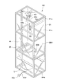
- the liquid container extracting device 90 has an upper part 91 a, a bottom part 91 b, and a side part 91 c, and an apparatus main body 91 for storing the outer container 5 and an apparatus main body 91. And a fixing device 95 for fixing the outer container 5.
- the exterior container 5 is placed on the bottom 91 b of the apparatus main body 91, and the exterior container 5 is fixed by a fixing device 95 attached to the side portion 91 c of the apparatus main body 91.
- an electric chain block (detaching device) 93 is attached to the upper portion 91a of the apparatus main body 91, and a chain 93a having a hook 93b attached to the tip extends downward from the electric chain block 93 (FIG. 16A). ) (B)).
- an acrylic cover plate 96 that covers the exterior container 5 housed inside is attached to the side portion 91c of the apparatus main body 91.
- the apparatus main body 91 has a vertically long rectangular parallelepiped shape as a whole, and the cover plate 96 is attached to the four surfaces of the side portion 91c.
- the front cover plate 96A is an open / close door
- a handle 96B is attached to the open / close door 96A.
- the fixing device 95 attached to the side portion 91c of the device main body 91 is composed of a steel frame having a quadrangular shape, but in order to prevent the resin-made outer container 5 from being damaged, the fixing device 95 95 may have a resin contact portion 95a that contacts the outer container 5 (see FIG. 16C).
- an apparatus main body 91 having a cover plate 96 attached thereto is prepared, and the outer container 5 is carried to the vicinity of the apparatus main body 91.
- the handle 96 ⁇ / b> B of the opening / closing door 96 ⁇ / b> A of the apparatus main body 91 is gripped, the opening / closing door 96 ⁇ / b> A is opened, and the outer container 5 is carried into the apparatus main body 91.
- the exterior container 5 enters below the fixing device 95 attached to the side portion 91c, and the upward movement of the exterior container 5 is restricted (fixed) by the fixing device 95.
- the fixing device 95 is attached to the side portion 91c in advance, and the upward movement of the outer container 5 is restricted when the outer container 5 enters below the fixing device 95. After mounting on the bottom portion 91b, the fixing device 95 may be disposed on the outer container 5 and attached to the side portion 91c.
- the operation portion 93c of the electric chain block 93 is attached to the tip of an operation line 93d extending outward from the apparatus main body 91, and the electric chain block 93 is operated by operating the operation portion 93c as shown in FIG.
- the chain 93a and the hook 93b are moved down (see FIG. 20).
- the liquid container 1 described above is stored in the outer container 5 disposed in the apparatus main body 91, and the spout 40 of the liquid container 1 is attached to the opening 5 a of the outer container 5. Therefore, the spout 40 is removed from the opening 5a of the outer container 5, and the spout 40 is pulled out slightly from the opening 5a (see FIG. 21). Next, the hook 93 b of the electric chain block 93 that has been lowered is hooked on the portion of the bag body 3 just below the spout 40.
- the electric chain 93 attached to the upper portion 91 a of the apparatus main body 91 is operated by operating the operation portion 93 c from the outside of the apparatus main body 91, and the opening 5 a is opened from the outer container 5. Accordingly, the bag body 3 of the liquid storage container 1 can be easily and easily extracted. In this case, since the cover plate 96 surrounding the outer container 5 is attached to the apparatus main body 91, the bag main body 3 can be safely extracted even if the chemical liquid remains in the bag main body 3.
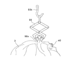
- an auxiliary tool 98 having a grip portion 98a is attached to the hook 93b of the electric chain block 93.
- the bag body 3 just below the spout 40 is gripped by the grip portion 98a of the auxiliary tool 98, and the electric chain block 93 is operated in this state as shown in FIG.
- the chain 93a and the hook 93b may be raised.
- the hook 93 b of the electric chain block 93 may be attached to the spout 40 via the auxiliary tool 99.
- a ring-shaped auxiliary tool 99 having an external screw 99a is prepared. Then, by engaging the outer screw 99a with the inner screw (not shown) of the spout 40, the auxiliary tool 99 and the spout 40 are firmly fixed (see FIG. 27).
- hook 93b of electric chain block 93 is hooked on auxiliary tool 99.
- the electric chain block 93 is operated as shown in FIG. 28 to raise the chain 93a and the hook 93b of the electric chain block 93.
- the liquid container extracting device 90 has one end portion 101a, the other end portion 101b, and the side portion 101c, and a device main body 101 for storing the outer container 5. And a first fixing device 95 ⁇ / b> A and a second fixing device 102 for fixing the outer container 5 disposed in the apparatus main body 101.
- the exterior container 5 is placed on the side portion 101 c of the apparatus main body 101, and the exterior container 5 is fixed by the first fixing device 95 and the second fixing device 102 attached to the side portion 101 c of the apparatus main body 101.
- an electric chain block (detaching device) 93 is attached to one end 101a of the apparatus main body 101, and a chain 93a having a hook 93b attached to the tip extends from the electric chain block 93 to the right (FIG. 29). (See (a) and (b)).
- an acrylic cover plate 96 that covers the exterior container 5 housed inside is attached to the side portion 101c of the apparatus main body 101.
- the apparatus main body 101 has a horizontally long rectangular parallelepiped shape as a whole, and the cover plate 96 is attached to four surfaces of the side portion 101c.
- the upper cover plate 96A is an open / close door, and a handle 96B is attached to the open / close door 96A.
- the first fixing device 95A and the second fixing device 102 attached to the side portion 101c of the apparatus main body 101 are made of a steel frame having a square shape, but damage the resin outer container 5.
- the first fixing device 95A and the second fixing device 102 may have a resin contact portion 95a that contacts the outer container 5 (see FIG. 16C).
- the first fixing device 95A may be a plate having an opening through which the spout 40 passes.
- the apparatus main body 101 having a cover plate 96 attached thereto is prepared, and the outer container 5 is carried to the vicinity of the apparatus main body 101.
- the handle 96B of the opening / closing door 96A of the apparatus main body 101 is grasped, the opening / closing door 96A is opened, the outer container 5 is carried into the apparatus main body 101, and the outer container 5 is placed on the side portion 101c of the apparatus main body 101.
- the outer container 5 is restricted from moving leftward by the first fixing device 95A, and the second fixing device 102 is restricted from moving upward by the second fixing device 102.
- the first fixing device 95A and the second fixing device 102 are attached to the side portion 101c in advance, and when the outer container 5 enters between the first fixing device 95A and the second fixing device 102, the outer container 5 Although the leftward movement and the upward movement are restricted, the first fixing device 95A and the second fixing device 102 are placed on the outer container 5 after the outer container 5 is placed on the side portion 101c of the apparatus main body 101.
- the first fixing device 95A and the second fixing device 102 may be attached to the side portion 101c.
- the operation portion 93c of the electric chain block 93 is attached to the tip of an operation line 93d extending outward from the apparatus main body 101.
- the electric chain block 93 is operated, and the chain 93a and the hook 93b is moved in the left-right direction.
- the above-described liquid storage container 1 is stored in the exterior container 5 disposed in the apparatus main body 101, and the spout 40 of the liquid storage container 1 is attached to the opening 5 a of the exterior container 5. Therefore, the spout 40 is removed from the opening 5a of the outer container 5, and the spout 40 is pulled out slightly from the opening 5a. Next, the hook 93 b of the electric chain block 93 that has moved to the right is hooked on the portion of the bag body 3 directly below the spout 40 via the auxiliary tool 98.
- the chain 93a and the hook 93b of the electric chain block 93 are moved to the left.
- the outer container 5 is restricted from moving leftward by the first fixing device 95 ⁇ / b> A, is restricted upward movement by the second fixing device 102, and is a bag hooked on the hook 93 b via the auxiliary tool 98.
- the main body 3 can be easily extracted from the outer container 5 to the left (in the pulling direction) through the opening 5a.
- the electric chain 93 attached to the one end 101 a of the apparatus main body 101 is operated by operating the operation section 93 c from the outside of the apparatus main body 91, and the opening 5 a is opened from the outer container 5.
- the bag body 3 of the liquid storage container 1 can be easily and easily pulled out via the. In this case, since the cover plate 96 surrounding the outer container 5 is attached to the apparatus main body 101, the bag main body 3 can be removed safely even if the chemical liquid remains in the bag main body 3.
- the liquid container extracting device 90 has an upper part 91a, a bottom part 91b, and a side part 91c, and an apparatus main body 91 for storing the outer container 5; And a fixing device 95 for fixing the outer container 5 disposed in the main body 91.
- the exterior container 5 is placed on the fixing device 95 of the apparatus main body 91. Further, the fixing device 95 regulates the downward movement of the outer container 5.
- an elevator (separating device) 93A is attached to the lower portion 91b of the apparatus main body 91 via an auxiliary tool 98.
- an acrylic cover plate 96 that covers the exterior container 5 housed inside is attached to the side portion 91c of the apparatus main body 91.
- the apparatus main body 91 has a vertically long rectangular parallelepiped shape as a whole, and the cover plate 96 is attached to the four surfaces of the side portion 91c.
- the front cover plate 96A is an open / close door
- a handle 96B is attached to the open / close door 96A.
- the fixing device 95 attached to the side portion 91c of the device main body 91 is composed of a steel frame having a quadrangular shape, but in order to prevent the resin-made outer container 5 from being damaged, the fixing device 95 95 may have a resin contact portion 95a that contacts the outer container 5 (see FIG. 16C).
- the fixing device 95 may be a plate having an opening through which the spout 40 is passed.
- an apparatus main body 91 having a cover plate 96 attached thereto is prepared, and the outer container 5 is carried to the vicinity of the apparatus main body 91.
- the handle 96B of the opening / closing door 96A of the apparatus main body 91 is grasped, the opening / closing door 96A is opened, and the outer container 5 is carried into the apparatus main body 91, and the outer container 5 is opened with the opening 5a and the spout 40 facing downward. It is placed on the fixing device 95 of the main body 91. In this case, the downward movement of the outer container 5 is restricted (fixed) by the fixing device 95. In this case, the fixing device 95 is previously attached to the side portion 91c.
- the operation line 93d of the elevator 93A extends outward from the apparatus main body 91, and moves the elevator 93A up and down by operating the operation unit 93c attached to the tip of the operation line 93d.
- the liquid container 1 described above is accommodated in the outer container 5 disposed in the apparatus main body 91, and the spout 40 of the liquid container 1 is attached to the opening 5 a of the outer container 5. Therefore, the spout 40 is removed from the opening 5a of the outer container 5, and the spout 40 is pulled out slightly from the opening 5a. Next, the spout 40 is gripped by the auxiliary tool 98.
- the elevator 93A is lowered by operating the operation unit 93c.
- the outer container 5 is restricted from moving downward by the fixing device 95, and the bag body 3 hooked on the auxiliary tool 98 can be easily moved downward (in the direction of pulling away) from the outer container 5 through the opening 5a. Can be extracted.
- the elevator 93A attached to the lower portion 91b of the apparatus main body 91 is operated by operating the operation portion 93c from the outside of the apparatus main body 91, and is then opened from the outer container 5 through the opening 5a.
- the bag body 3 of the liquid storage container 1 can be easily and easily pulled out.
- the cover plate 96 surrounding the outer container 5 is attached to the apparatus main body 91, the bag main body 3 can be safely extracted even if the chemical liquid remains in the bag main body 3.
- the liquid container extracting device 90 has an upper part 91a, a bottom part 91b, and a side part 91c, and an apparatus main body 91 for storing the outer container 5, and an apparatus And a fixing device 95 for fixing the outer container 5 disposed in the main body 91.
- an electric chain block (detaching device) 93 is attached to the upper portion 91a of the apparatus main body 91, and a chain 93a having a hook 93b attached to the tip extends downward from the electric chain block 93.
- an acrylic cover plate 96 that covers the exterior container 5 housed inside is attached to the side portion 91c of the apparatus main body 91.
- the apparatus main body 91 has a vertically long rectangular parallelepiped shape as a whole, and the cover plate 96 is attached to the four surfaces of the side portion 91c.
- the front cover plate 96A is an open / close door
- a handle 96B is attached to the open / close door 96A.
- the fixing device 95 attached to the side portion 91c of the device main body 91 is composed of a steel frame having a quadrangular shape.
- an apparatus main body 91 having a cover plate 96 attached thereto is prepared, and the outer container 5 is carried to the vicinity of the apparatus main body 91.
- the handle 96B of the opening / closing door 96A of the apparatus main body 91 is grasped, the opening / closing door 96A is opened, and the outer container 5 is carried into the apparatus main body 91 upside down.
- the outer container 5 is opened through the opening 5a and the spout 40. It is placed on the fixing device 95 of the apparatus main body 91 facing downward.
- the operation portion 93c of the electric chain block 93 is attached to the tip of an operation line 93d extending outward from the apparatus main body 91.
- the electric chain block 93 is operated, and the chain 93a and the hook 93b are connected. Lower.
- the hook 93 b is hooked on the engaging portion 105 provided at the bottom of the outer container 5 placed upside down on the fixing device 95.
- the liquid storage container 1 described above is stored, and the spout 40 of the liquid storage container 1 is attached to the opening 5a of the exterior container 5.
- the spout 40 is previously removed from the opening 5a of the outer container 5, and the spout 40 is pulled out slightly from the opening 5a.
- the bag body 3 in the vicinity of the spout 40 is gripped by the auxiliary tool 98.
- the auxiliary tool 98 is hooked on the fixing device 95.
- the electric chain block 93 is operated to further raise the chain 93a and the hook 93b. By lifting the exterior container 5 hooked on the hook 93b, the bag body 3 can be easily pulled out downward (in the pulling direction) from the exterior container 5 through the opening 5a.
- the electric chain 93 attached to the upper portion 91 a of the apparatus main body 91 is operated by operating the operation portion 93 c from the outside of the apparatus main body 91, and the opening 5 a is opened from the outer container 5. Accordingly, the bag body 3 of the liquid storage container 1 can be easily and easily extracted. In this case, since the cover plate 96 surrounding the outer container 5 is attached to the apparatus main body 91, the bag main body 3 can be safely extracted even if the chemical liquid remains in the bag main body 3.
- the liquid container extracting device 90 has one end 101 a, the other end 101 b, and the side 101 c, an apparatus main body 101 for storing the outer container 5, and an inside of the apparatus main body 101.
- a fixing device 111 for fixing the bag body 3 in the outer container 5 disposed in the container is fixed to the one end 101 a of the device main body 101 and holds the bag main body 3 of the liquid container 1.
- an electric chain block (separating device) 93 is attached to the other end 101b of the apparatus main body 101.
- a chain 93 a having a hook 93 b attached to the tip extends from the electric chain block 93, and the chain 93 c is engaged with an engaging portion 105 provided at the bottom of the outer container 5.
- an acrylic cover plate 96 that covers the exterior container 5 housed inside is attached to the side portion 101c of the apparatus main body 101.
- the apparatus main body 101 has a horizontally long rectangular parallelepiped shape as a whole, and the cover plate 96 is attached to four surfaces of the side portion 101c.
- the front cover plate 96A is an open / close door, and a handle 96B is attached to the open / close door 96A.
- a pressing device 110 having a pressing tool 110 a for slidably pressing the outer container 5 is provided in the device main body 101.
- the pressing member 110a of the pressing device attached to the device main body 101 is composed of a ring-shaped elastic hard resin frame having an opening.
- the apparatus main body 101 having a cover plate 96 attached thereto is prepared, and the outer container 5 is carried to the vicinity of the apparatus main body 101.
- the handle 96B of the opening / closing door 96A of the apparatus main body 101 is gripped, the opening / closing door 96A is opened, the outer container 5 is carried into the apparatus main body 101, and the outer container 5 is pressed by the pressing device 110 attached to the apparatus main body 101. It is held by the tool 110a.
- the operation portion 93c of the electric chain block 93 is attached to the tip of an operation line 93d extending outward from the apparatus main body 101.
- the electric chain block 93 is operated, and the chain 93a and the hook 93b is moved in the left-right direction.
- the above-described liquid storage container 1 is stored in the exterior container 5 disposed in the apparatus main body 101, and the spout 40 of the liquid storage container 1 is attached to the opening 5 a of the exterior container 5. Therefore, the spout 40 is removed from the opening 5a of the outer container 5, and the spout 40 is pulled out slightly from the opening 5a.
- the fixing device 111 attached to the one end portion 101 a of the apparatus main body 101 is hooked on the portion of the bag main body 3 immediately below the spout 40.
- the electric chain 93 attached to the one end 101 a of the apparatus main body 101 is operated by operating the operation section 93 c from the outside of the apparatus main body 91, and the opening 5 a is opened from the outer container 5.
- the bag body 3 of the liquid storage container 1 can be easily and easily pulled out via the. In this case, since the cover plate 96 surrounding the outer container 5 is attached to the apparatus main body 101, the bag main body 3 can be removed safely even if the chemical liquid remains in the bag main body 3.
- the liquid container extracting device 90 has an upper part 91a, a bottom part 91b, and a side part 91c, an apparatus main body 91 for storing the outer container 5, and an apparatus main body 91. And a fixing device 111 for fixing the bag body 3 in the outer container 5.
- the fixing device 111 is fixed to the upper portion 91 a of the device main body 101 and holds the bag main body 3 of the liquid storage container 1.
- an acrylic cover plate 96 that covers the exterior container 5 housed inside is attached to the side portion 91c of the apparatus main body 91.
- the apparatus main body 91 has a vertically long rectangular parallelepiped shape as a whole, and the cover plate 96 is attached to the four surfaces of the side portion 91c.
- the front cover plate 96A is an open / close door
- a handle 96B is attached to the open / close door 96A.
- a pressing device 110 having a pressing tool 110a for slidably pressing the outer container 5 is provided.
- the presser 110a of the presser device 110 attached to the device main body 101 is composed of a ring-shaped elastic hard resin frame having an opening.
- the presser 110a is attached to an elevator (separating device) 93A, and an operation line 93d of the elevator 93A extends outward from the apparatus main body 91 to operate an operation portion 93c attached to the tip of the operation line 93d.
- the outer casing 5 can be moved up and down by the elevator 93A.
- an apparatus main body 91 having a cover plate 96 attached thereto is prepared, and the outer container 5 is carried to the vicinity of the apparatus main body 91.
- the handle 96B of the opening / closing door 96A of the apparatus main body 91 is grasped, the opening / closing door 96A is opened, and the outer container 5 is carried into the apparatus main body 91, and the outer container 5 is opened with the opening 5a and the spout 40 facing upward. It is held by a pressing tool 110 a of a pressing device 110 attached to the main body 91.
- the liquid container 1 described above is accommodated in the outer container 5 disposed in the apparatus main body 91, and the spout 40 of the liquid container 1 is attached to the opening 5 a of the outer container 5. Therefore, the spout 40 is removed from the opening 5a of the outer container 5, and the spout 40 is pulled out slightly from the opening 5a.
- the fixing device 111 attached to the upper portion 91 a of the device main body 91 is hooked on the portion of the bag main body 3 in the vicinity of the spout 40.
- the elevator 93A is lowered to lower the outer container 5 held by the pressing device 110.
- the bag body 3 is restricted from moving downward by the fixing device 111 and fixed.
- the bag body 3 hooked on the device 111 can be easily pulled out downward (in the pulling direction) from the outer container 5 through the opening 5a.
- the elevator 93A attached to the apparatus main body 91 is operated by operating the operation portion 93c from the outside of the apparatus main body 91, and liquid is stored from the outer container 5 through the opening 5a.
- the bag body 3 of the container 1 can be easily and easily extracted. In this case, since the cover plate 96 surrounding the outer container 5 is attached to the apparatus main body 91, the bag main body 3 can be safely extracted even if the chemical liquid remains in the bag main body 3.
- the mode in which the outer container 5 and the liquid storage container 1 are relatively separated from each other in the vertical direction and the horizontal direction has been described. Further, the outer container 5 and the liquid storage container 1 may be relatively separated from each other also “obliquely upward” or “obliquely downward”.
- the liquid container extracting device 90 includes a fixing device 95 for fixing the outer container 5.
- the outer container 5 is fixed by the fixing device 95, and an electric chain block (detaching device) 93 supported by the rail 115 is attached above the fixing device 95.
- a chain 93a to which the hook 93b is attached extends downward.
- the liquid container extracting device 90 includes a fixing device 95 and an electric chain block 93, but the device main body 91 is not necessarily provided.
- the fixing device 95 is made of a square steel frame, but the fixing device 95 is made of a resin that comes into contact with the outer container 5 in order to prevent the resin outer container 5 from being damaged. You may have the contact part 95a (refer FIG.16 (c)).
- the operation portion 93c of the electric chain block 93 is attached to the tip of an operation line 93d extending outward from the apparatus main body 91, and the electric chain block 93 is operated by operating the operation portion 93c as shown in FIG. Actuate to lower the chain 93a and hook 93b.
- the liquid container 1 described above is stored in the outer container 5, and the spout 40 of the liquid container 1 is attached to the opening 5 a of the outer container 5. Therefore, the spout 40 is removed from the opening 5a of the outer container 5, and the spout 40 is pulled out slightly from the opening 5a (see FIG. 21). Next, the hook 93 b of the electric chain block 93 that has been lowered is hooked on the portion of the bag body 3 just below the spout 40.
- the electric chain 93 attached above the fixing device 95 is operated by operating the operating portion 93c from the outside of the fixing device 95, so that the outer container 5 is opened via the opening 5a.
- the bag body 3 of the liquid storage container 1 can be easily and easily pulled out.
- the liquid storage container extraction device 90 has an upper portion 91a, a bottom portion 91b, and a side portion 91c, and is disposed within the device main body 91 and the device main body 91 for storing the outer container 5. And a fixing device 95 for fixing the outer container 5.
- the exterior container 5 is placed on the bottom 91 b of the apparatus main body 91, and the exterior container 5 is fixed by a fixing device 95 attached to the side portion 91 c of the apparatus main body 91.
- an electric chain block (detaching device) 93 is attached to the upper portion 91a of the apparatus main body 91, and a chain 93a having a hook 93b attached to the tip extends downward from the electric chain block 93.
- an acrylic cover plate 96 that covers the exterior container 5 housed inside is attached to the side portion 91c of the apparatus main body 91.
- the apparatus main body 91 has a vertically long rectangular parallelepiped shape as a whole, and the cover plate 96 is attached to the four surfaces of the side portion 91c.
- the cover plate 96A1 in the lower front part is an open / close door, and a handle 96B1 is attached to the open / close door 96A1.
- the fixing device 95 attached to the side portion 91c of the device main body 91 is composed of a steel frame having a quadrangular shape, but in order to prevent the resin-made outer container 5 from being damaged, the fixing device 95 95 may have a resin contact portion 95a that contacts the outer container 5 (see FIG. 16C).
- a transport conveyor (transport mechanism) 120 for transporting the outer container 5 is provided in a direction orthogonal to the pulling direction connecting the electric chain block 93 and the fixing device 95.
- a transport conveyor (transport mechanism) 120 for the outer container 5 is disposed adjacent to the cover plate 96 ⁇ / b> A ⁇ b> 1 at the lower portion of the lower surface of the apparatus main body 91.
- the conveyor 120 is driven by a driving roller 121 and is disposed in a direction orthogonal to a pulling direction connecting the electric chain block 93 and the fixing device 95.
- an apparatus main body 91 having a cover plate 96 attached thereto is prepared, and the outer container 5 is carried by the transfer conveyor 120 to the vicinity of the apparatus main body 91.
- the handle 96 ⁇ / b> B ⁇ b> 1 of the opening / closing door 96 ⁇ / b> A ⁇ b> 1 of the apparatus main body 91 is gripped, the opening / closing door 96 ⁇ / b> A ⁇ b> 1 is opened, and the exterior container 5 is loaded into the apparatus main body 91.
- the exterior container 5 enters below the fixing device 95 attached to the side portion 91c, and the upward movement of the exterior container 5 is restricted (fixed) by the fixing device 95.
- the fixing device 95 is attached to the side portion 91c in advance, and the upward movement of the outer container 5 is restricted when the outer container 5 enters below the fixing device 95. After mounting on the bottom portion 91b, the fixing device 95 may be disposed on the outer container 5 and attached to the side portion 91c.
- the operation portion 93c of the electric chain block 93 is attached to the tip of an operation line 93d extending outward from the apparatus main body 91.
- the electric chain block 93 is activated, and the chain 93a and the hook 93b is lowered.
- the liquid container 1 described above is stored in the outer container 5 disposed in the apparatus main body 91, and the spout 40 of the liquid container 1 is attached to the opening 5 a of the outer container 5. Therefore, the spout 40 is removed from the opening 5a of the outer container 5, and the spout 40 is pulled out slightly from the opening 5a. Next, the hook 93 b of the electric chain block 93 that has been lowered is hooked on the portion of the bag body 3 just below the spout 40.
- the handle 96B1 can be gripped to open the opening / closing door 96A1, the outer container 5 can be discharged from the apparatus main body 91 to the outside, and then conveyed outside the outer container 5 by the transfer conveyor 120.
- the electric chain 93 attached to the upper portion 91 a of the apparatus main body 91 is operated by operating the operation portion 93 c from the outside of the apparatus main body 91, and the opening 5 a is opened from the outer container 5. Accordingly, the bag body 3 of the liquid storage container 1 can be easily and easily extracted. In this case, since the cover plate 96 surrounding the outer container 5 is attached to the apparatus main body 91, the bag main body 3 can be safely extracted even if the chemical liquid remains in the bag main body 3.
- the heavy exterior container 5 can be transported to the vicinity of the apparatus main body 5 using the transport conveyor 120, or the exterior container 5 in the apparatus main body 5 can be taken out and then discharged outward by the transport conveyor 120. it can.
- the embodiment in which the transport conveyor (transport mechanism) 120 of the outer container 5 is disposed adjacent to the cover plate 96A1 in the lower part of the lower surface of the apparatus main body 91 has been described.
- the transport conveyor (transport mechanism) 120 is exposed at the bottom 91 b of the apparatus main body 91, and the exterior container 5 is placed on the transport conveyor (transport mechanism) 120.
- the outer container 5 is carried into the apparatus main body 91 by the transfer conveyor (transfer mechanism) 120, or the outer container 5 in the apparatus main body 91 is moved outward from the apparatus main body 91 by the transfer conveyor (transfer mechanism) 120.
- the bag body 3 can be removed more easily.
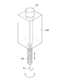
- a ninth embodiment shown in FIG. 36 is different from the electric chain block 93 in the embodiment shown in FIGS. 15 to 22 in that a screw rod 125 having a hook 93 at the tip and the screw rod 126 are rotatable.
- the other structure is substantially the same as the embodiment shown in FIGS. 15 to 22.
- the holding body 126 is supported by an upper portion 91 a of the apparatus main body 91 (see FIG. 15), and a rotation driving unit 127 that rotates the screw rod 125 and moves up and down along the holding body 126 on the upper surface of the holding body 126. Installed.
- the screw rod 125 is rotated with respect to the holding body 126 by the rotation driving unit 127 and is moved up and down along the holding body 126.
- the bag main body 3 can be pulled up while being rotated with respect to the outer container 5 fixed to the fixing device 95 by hooking the hook 93 on the bag main body 3. it can.
- the bag body 3 can be smoothly and reliably extracted from the opening 5a of the outer container 5.
- the separating device is constituted by a screw rod 125 having a hook 93, a holding body 126 that rotatably holds the screw rod 125, and a rotation driving unit 127 attached to the upper surface of the holding body 126. Composed.
- a liquid storage container extraction device 90 has a plurality of device main bodies 91 arranged in a straight line adjacent to each other, and the outer container 5 is placed in each device main body 91.
- a fixing device 95 for fixing is provided.
- FIG. 37 is a plan view showing the liquid container extracting device 90.
- the plurality of device main bodies 91 of the liquid container extracting device 90 are arranged adjacent to each other, and the guide rails 130 extend in the horizontal direction through the respective device main bodies 91.
- a single electric chain block 93 (separating device) is movable along the guide rail 130 along a direction (horizontal direction) orthogonal to the separating direction (vertical direction) connecting the fixing device 95 and the electric chain block 93. It has become.
Landscapes
- Engineering & Computer Science (AREA)
- Mechanical Engineering (AREA)
- Control And Other Processes For Unpacking Of Materials (AREA)
- Packages (AREA)
Abstract
【課題】大型の外装容器から袋本体を開口部を介して容易に抜き取ること。 【解決手段】液体収納容器の抜き取り装置90は外装容器5を囲む装置本体91と、装置本体91内に配置された外装容器5を固定する固定装置95とを備えている。外装容器5内に収納された液体収納容器1の袋本体3が電動チェーンブロック93のフック93cに引掛けられる。電動チェーンブロック93を作動させてフック93cを上昇させることにより、袋本体3が外装容器5から開口部5を介して引き抜かれる。
Description
本実施の形態は、とりわけ工業薬品分野、医薬品や化粧品原料分野等で流動性内容物の保管や輸送に供せられる外装容器内に収容して使用される液体収納容器を外装容器から抜き取るための液体収納容器の抜き取り装置および液体収納容器の抜き取り方法に関する。
従来、工業薬品分野、医薬品や化粧品原料分野等で、保管や輸送にアルミニウム、スチール、ステンレス、ファイバーボード等で作られた外装容器の内部に配置され、流動性内容物を収容する液体収納容器が使用されている。
このような液体収納容器は、使用済みの液体収納容器を外装容器から取り出し、新たな液体収納容器を外装容器内にセットするだけで再使用することができるために、例えば、液体収納容器を使用せずに直にスチール等の外装容器に流動性内容物を充填する場合に比べて、洗浄する手間等が省けるなどの利点があり、工業薬品、医薬品や化粧品原料の容器として広く使用されている。
また液体収納容器として、袋本体と、袋本体に取付けられた注出口とを有するものが知られている。また注出口は袋本体にヒートシールされた注出口取付部と、注出口取付部から袋本体の外方へ突出する注出口本体とを有する。このような液体収納容器は、まずコンパクトに折畳まれ外装容器の開口部から外装容器内に挿入される。
その後液体収納容器内に窒素ガスを供給して液体収納容器を外装容器内部で膨らませる。
次に膨らませた液体収納容器内に内容液を充填している。
ところで、外装容器は一体に形成された胴部と、底部と、天板とを有し、200L以上の容積をもつ。また、開口部は天板に設けられ、この開口部を介して液体収納容器の袋本体が外装容器内に収納され、かつ開口部を介して袋本体が外装容器から外方へ抜き取られる。外装容器は200L以上の容積をもつため、この大型の外装容器から袋本体を抜き取る作業は容易ではない。
本実施の形態はこのような点を考慮してなされたものであり、大型の外装容器から袋本体を開口部を介して容易に抜き取ることができる液体収納容器の抜き取り装置および液体収納容器の抜き取り方法を提供することを目的とする。
本実施の形態は、開口部を有する外装容器内に配置され、注出口と袋本体とを有し、前記袋本体の幅が前記開口部の内径より大きな液体収納容器の前記袋本体を前記開口部を介して前記外装容器の外方へ抜き取る液体収納容器の抜き取り装置において、前記外装容器および前記液体収納容器のうちいずれか一方を固定する固定装置と、前記外装容器と前記液体収納容器のうち他方を引っ張り、前記外装容器と前記液体収納容器を相対的に引離す引離し装置と、を備えた液体収納容器の抜き取り装置である。
本実施の形態は、前記引離し装置は前記外装容器と前記液体収納容器を上下方向に相対的に引離す、液体収納容器の抜き取り装置であってもよい。
本実施の形態は、前記引離し装置は前記外装容器と前記液体収納容器を水平方向に相対的に引離す、液体収納容器の抜き取り装置であってもよい。
本実施の形態は、前記固定装置は前記外装容器を固定するとともに、前記外装容器に当接する当接部を有し、この当接部は樹脂製となっている液体収納容器の抜き取り装置であってもよい。
本実施の形態は、前記固定装置または前記引き離し装置のうち、少なくともいずれか一方を収納する装置本体を更に備えた、液体収納容器の抜き取り装置であってもよい。
本実施の形態は、前記装置本体に、前記外装容器および前記液体収納容器を覆う覆い板を取付けた、液体収納容器の抜き取り装置であってもよい。
本実施の形態は、前記外装容器は200L以上の容積を有する、液体収納容器の抜き取り装置であってもよい。
本実施の形態は、前記引き離し装置は前記液体収納容器を引っ張るようになっており、前記引き離し装置は前記液体収納容器を回転させる回転機構を有する、液体収納容器の抜き取り装置であってもよい。
本実施の形態は、前記引き離し装置は、前記固定装置と前記引き離し装置を結ぶ引き離し方向に対して直交する方向に沿って移動可能となる、液体収納容器の抜き取り装置であってもよい。
本実施の形態は、前記引き離し装置と前記固定装置とを結ぶ引き離し方向に対して直交する方向に設けられ、前記外装容器を搬送する搬送機構を更に備えた、液体収納容器の抜き取り装置であってもよい。
本実施の形態は、開口部を有する外装容器内に配置され、注出口と袋本体とを有し、前記袋本体の幅が前記開口部の内径より大きな液体収納容器の前記袋本体を前記開口部を介して前記外装容器の外方へ抜き取る液体収納容器の抜き取り方法において、固定装置に、前記外装容器および前記液体収納容器のうちいずれか一方を固定する工程と、引離し装置により、前記外装容器と前記液体収納容器のうち他方を引っ張って前記外装容器と前記液体収納容器を相対的に引離す工程と、を備えた液体収納容器の抜き取り方法である。
以上のように本実施の形態によれば、大型の外装容器から液体収納容器の袋本体を開口部を介して容易に抜き取ることができる。
<第1の実施の形態>
以下、図面を参照して本発明を実施するための第1の実施の形態を説明する。ここで図1乃至図28は、本発明の第1の実施の形態を示す図である。
以下、図面を参照して本発明を実施するための第1の実施の形態を説明する。ここで図1乃至図28は、本発明の第1の実施の形態を示す図である。
まず本実施の形態による液体収納容器の抜き取り装置の対象となる液体収納容器について説明する。
ここで図1は液体収納容器を示す平面図であり、図2(a)(b)は外装容器と液体収納容器の組合体を示す図であり、図3は外装容器と液体収納容器の組合体を示す側断面図であり、図4は膨らまし作用を示す図である。
外装容器と液体収納容器の組合体は、天板中央部を通る第1中央部L1からずれた(外れた)位置に設けられた開口部5aを有する合成樹脂製の外装容器5と、この外装容器5内に配置された液体収納容器1とを備えている。ここで外装容器5の開口部5aから後述する袋本体3が挿入される。
なお、外装容器5は、外装容器5の天板に開口部5a以外の開口部5Aが設けられている(図2(a)(b)参照)。
この場合、本実施の形態においては開口部5Aには液体収納容器1を挿入しないが、開口部5Aは、液体収納容器1を外装容器5内へ挿入して開口部5aへ固定する際に、外装容器5内の液体収納容器1の状態を確認するための目視穴として使用できる。
外装容器5は例えば200L以上の容量、585mmの直径、880mmの高さをもち、開口部5aおよび開口部5Aはいずれも80mmの直径をもつ。
なお、外装容器5として、鋼製ドラムを用いることもでき、この鋼製ドラムは例えば200L以上の容量、580mmの直径、890mmの高さをもち、開口部5aは72mmの直径をもち、開口部5Aは32mmの直径をもつ。
また液体収納容器1は、矩形状の袋本体3と、袋本体3のうち上縁3a中央部を通る第2中央部L2からずれた(外れた)位置に設けられた注出口40とを有し、注出口40は外装容器5の開口部5a内に装着される。
次に液体収納容器1について更に述べる。
液体収納容器1は、外袋20と内袋21とを重ね合わせた多重フィルム2を、内袋21同士が対向するように重ね合わせて合計4枚とし、その四辺をヒートシールしてヒートシール部10を形成した上述した袋本体3と、この袋本体3の上縁3aに配置され内袋21間に予め熱融着された上述した注出口40とを備えている。
尚、本実施の形態では、袋本体3は多重フィルム2を内袋21同士が対向するようにして積層し、四辺をヒートシールしてヒートシール部10を形成することにより得られるが、これに限定されるものではなく、例えば、多重フィルム2を内袋21同士が対向するようにして折り曲げた後、重なり合った外周辺の三辺をヒートシールして形成してもよい。
また、ヒートシール部10の内縁各部は、その内縁が弧状となるよう形成してもよい。これによって、角部に流動性内容物が残存し難い構造となる。また、袋本体は必ずしも多重フィルムから構成する必要はなく、包本体3のフィルム構成は内容物や量に応じて適宜選定できる。
なお、上述のように袋本体3は2枚の多重フィルム2を重ね合わせ、周縁をヒートシールしてヒートシール部10を形成することにより得られる。この場合、袋本体3は上縁3aと、底縁3bと、2側縁3c、3cとを有する矩形形状を有している。また上縁3aは2本の上縁ヒートシール部10aを含み、底縁3bは1本の底縁ヒートシール部10bを含み、各側縁3c、3cは1本の側縁ヒートシール部10cを有し、これら上縁ヒートシール部10aと、底縁ヒートシール部10bと側縁ヒートシール部10cとによりヒートシール部10が構成されている。
また袋本体3の上縁3aは、上述のように2本の上縁ヒートシール部10aを含む。このように上縁3aのヒートシール部10aを2本に分けることにより、例えば上縁3aに2本分のヒートシール部10aの幅をもつ1本のヒートシール部を形成する場合に比べて、上縁3aを比較的軟質に構成することができる。また、上縁ヒートシール部10aは、2本に限定されるものではなく、1本としていても良いし、3本以上としていても良い。
なお、本実施の形態を実施するに際しては、多重フィルム2は外袋20と内袋21とを重ね合わせて構成する2層構造に限定されることはなく、1枚以上の中袋22をさらに有する3層構造としても良く、内袋21あるいは外袋20のみからなる単層構造としていても良い。
また注出口40は、袋本体3の上縁3aに熱融着された注出口取付部50と、該注出口取付部50に連接され袋本体3から外方へ突出する注出口本体41とを有し、注出口本体41の上端には注出口フランジ42が設けられている。また、図1に示すように、注出口40は注出口取付部50で多重フィルム2の内袋21間に熱融着されている。
注出口40の注出口取付部50は、図5乃至図9に示すように、中央部51と、中央部51の両側に設けられ中央部51の厚みより薄肉となる薄肉部52をもつ楕円筒体からなり、扁平状で中央部51に貫通穴45を有する。通常、注出口40を注出口取付部50において多重フィルム2の内袋21間に熱融着する際に、内袋21間と注出口取付部50の端部で囲まれる2つの領域に隙間ができて密封不良となり易い。これを防止するために両側に薄肉部52を設け、熱融着時にこの薄肉部52を溶融することにより隙間ができることを防止する。
また注出口40の注出口本体41は、断面形状が略U字形状の筒状体からなり、その上端周縁に注出口フランジ42が設けられている。注出口本体41の底部43には、開口44が形成されている。注出口40を外装容器5へ装着した後は、この開口44によって、外装容器5の外部と、液体収納容器1と外装容器5との間の空間の通気を確保することができ、使用時に内容液を汲み出す際には、この開口44を通じて液体収納容器1と外装容器5との間に気体を封入して、液体収納容器1の外部から圧力をかけて液体収納容器1内部の内容液の汲み出しをスムースに行うことができる。
また、図3に示すように、注出口40の注出口本体41には外ねじ41Aが設けられ、外装容器5の開口部5aには、外ねじ41Aに係合する内ねじ5Bが設けられている。そして注出口40の外ねじ41Aを開口部5aの内ねじ5Bにねじ込むことにより、注出口40を開口部5a内に確実に固定することができる。この場合、注出口40の注出口フランジ42は外装容器5に形成された開口部5aに装着され、液体収納容器1が外装容器5内で支持される。
なお、注出口40の外ねじ41Aと、開口部5aの内ねじ5Bとにより固定手段が構成される。
注出口40は、好ましくは射出成形法にて製造される。これに用いる樹脂としては射出成形可能な樹脂であれば特に限定するものではないが、多重フィルム2の内袋21の内面を構成する樹脂と熱融着により接合されるために、内袋21の内面を構成する樹脂により適宜選択する必要があるが、通常は高温時でも剛性があり、低温時において脆化し難い高密度ポリエチレンが好適である。
次に、袋本体3を構成する多重フィルム2について説明する。本実施の形態においては、多重フィルム2は外袋20を構成するフィルムと内袋21を構成するフィルムとで構成される。
図10に示すように、袋本体3の外袋20としては未延伸ナイロン(厚さ20μm)20a/直鎖状低密度ポリエチレン(厚さ40μm)20bの積層体を用いることができ、内袋21としては直鎖状低密度ポリエチレン(厚さ70μm)を用いることができる。
この場合、外袋20は未延伸ナイロン20aを含むため、外袋20としてはその伸長度を増加させることができ、例えば外袋20は300%~500%の伸長度をもつ。このように外袋20は高い伸長度をもつことができるため、袋本体3を全体として軟質とすることができ、後述のように外装容器5内に袋本体3を挿入し、この袋本体3内に窒素ガスやクリーンドライエアーを供給して袋本体3を外装容器内で膨らませる際、スムースに袋本体3を膨らませることができる。
なお、袋本体3の材料としては上述したものに限られることはない。
例えば内袋21の材料としては、低密度ポリエチレン、低密度ポリエチレンと直鎖状低密度ポリエチレンのような材料を用いることができる。
また外袋20の材料としては、伸長度が300%~500%のもの、例えば低密度ポリエチレンと直鎖状低密度ポリエチレンのような材料を用いることができる。
次に、液体収納容器1の、外装容器5への収納形態について説明する。まず、液体収納容器1の袋本体3を縦方向折曲線11に沿って折畳むことによりじゃ腹部12が形成される(図12)。このようにじゃ腹部12が形成された袋本体3を上方横方向折曲線15aと下方横方向折曲線15bを介して折畳むことにより折畳み部16が形成される(図13)。
その後袋本体3が折曲線13に沿って折曲げられて三角折曲部14が形成される(図14)。
このようにして図11(a)(b)(c)に示すように、袋本体3にじゃ腹部12と、折畳み部16と、三角折曲部14とが形成された液体収納容器1が準備される。尚、じゃ腹部12を形成する工程と、折畳み部16を形成する工程とは、どちらを先に行っても良く、図11(a)(b)(c)は、じゃ腹部12を先に形成した態様を例示している。
ここで、便宜上、図12では折畳み部16を省略しており、図13ではじゃ腹部12を省略している。
次に図2(a)(b)に示すように、液体収納容器1は折畳まれて縦方向に細長状に形成され、液体収納容器1は開口部5aから外装容器5内に挿入される。
次に液体収納容器1の注出口40が外装容器5の開口部5aに装着される。この場合、まず注出口40を開口部5aに対して回転させる。このようにして開口部5aの内ねじ5Bに注出口40の外ねじ41Aをねじ込み、開口部5aの内ねじ5Bに注出口40の外ねじ41Aを係合させる。次に注出口40の注出口本体41の注出口フランジ42が外装容器5の開口部5aに当接し、注出口40の回転が停止する。
このようにして注出口40を開口部5aに堅固に固定することができる。
この場合、図4に示すように、後述する液体収納容器1の注出口40が外装容器5の開口部5aに装着され、液体収納容器1の袋本体3が外側容器5の内部で緩やかに平面状に拡がった際に、注出口取付部50の幅方向は、外装容器5の第1中央部L1と開口部5aとを結ぶ直線L3と平行し、また外装容器5の開口部5aの第1中央部L1からのずれ方向(図4(a)の左方向)は、液体収納容器1の注出口40の第2中央部L2からのずれ方向(図4(a)の左方向)と同一方向を向く様に、内ねじ5Aと、外ねじ41Aとが設けられる。ここで、注出口取付部50の幅方向とは、扁平状に延びる注出口取付部50の扁平方向と平行する方向であって、貫通穴45に対して直交する方向をいう。
ここで、外装容器5の第1中央部L1と開口部5aとを結ぶ直線L3とは、開口部5aから第1中央部L1へ垂線を引いたときの垂線を指す。このとき、開口部5aには大きさがあるため、開口部5aの上方から見たときの中央を垂線が必ずしも通らず、開口部5aの上方から見たときの縁に接して垂線が通る場合をも含み、開口部5aの上方から見たときの中央と開口部5aの上方から見たときの縁の間を通る場合をも含む。また、本実施の形態において、「平行」とは、幾何学的な意味において厳密に二線が直線である状態に加えて、二線が曲線である状態であることを含み、二線が直線である状態かつ厳密に二線が交わらない状態に加えて、二線が角度を成す状態であることも含み、二線が角度を成す状態における角度が20度以下の状態を指す。好ましくは角度が10度以下の状態であり、より好ましくは角度が5度以下の状態である。また、本実施の形態において、「同一方向」とは、ふたつの方向が厳密に一致する状態に加えて、ふたつの方向が角度を成す状態であることも含み、ふたつの方向の成す角度が20度以下の状態を指し、好ましくは角度が10度以下の状態であり、より好ましくは角度が5度以下の状態である。
次に液体収納容器1の注出口40に膨らまし治具(図示せず)が装着され、この膨らまし治具を用いて液体収納容器1内に窒素ガスまたはクリーンドライエアーが供給されて、外装容器5内で液体収納容器1の袋本体3が膨らむ。
次に外装容器5内で液体収納容器1を膨らませる作用について、以下詳述する。
外装容器5内に液体収納容器1を挿入した場合、まず液体収納容器1の袋本体3のうち折畳み部16より下方の部分が自重により落下し、その後、縦方向折曲線11を介してじゃ腹状に折畳まれた袋本体3のじゃ腹部12に、平坦状に戻る力が働き、袋本体3のじゃ腹部12が緩やかに平面状に拡がる。
次に上述のように、液体収納容器1内に膨らまし治具を用いて窒素ガスまたはクリーンドライエアーを供給することにより、袋本体3が膨らむ。この時、緩やかに平面状に拡がった袋本体3は、自身の表面に対して垂直方向へ、立体的に膨らむ。
この場合、袋本体3の上方部に、折曲線13を介して折曲げることにより形成された三角折曲部14が形成されているため、袋本体3が拡がる時に袋本体3の上縁3aの隅部が外装容器5の開口部5aに引掛かることはなく、外装容器5内で袋本体3が充分に拡がらせることができ、さらに袋本体3が損傷することも防止できる。
また袋本体3の上縁3aは2本の上縁ヒートシール部10aを含むため、幅広のヒートシール部を含む場合に比べて上縁3aを軟質に構成することができ、袋本体3をよりスムースに外装容器5内で拡げることができる。さらにまた袋本体3の外袋20は300%~500%の伸長度を有するため、袋本体3の柔軟性を高めて、袋本体3の拡張作用を容易に行なうことができる。
また、液体収納容器1の注出口40が外装容器5の開口部5aに装着されたときに、液体収納容器1の袋本体3は、外側容器5の内部で、前述の様に緩やかに平面状に拡がる。
この際、注出口取付部50の幅方向は、外装容器5の第1中央部L1と開口部5aとを結ぶ直線L3と平行し、外装容器5の開口部5aの第1中央部L1からのずれ方向は、注出口40の第2中央部L2からのずれ方向と同一方向を向く。このため、開口部5aが外装容器5の第1中央部L1からずれ、かつ注出口40が液体収納容器1の第2中央部L2からずれていても、液体収納容器1の袋本体3内に窒素ガスまたはクリーンドライエアーを供給することにより、外装容器5内において液体収納容器1の袋本体3を確実に膨らませることができる(図4参照)。すなわち、注出口取付部50の幅方向は、外装容器5の第1中央部L1と開口部5aとを結ぶ直線L3に平行するため、液体収納容器1の袋本体3の幅方向は、外装容器5の直径方向と同一方向を向く。外装容器5内において袋本体3を膨らませる際、袋本体3は自身の表面に対して垂直方向へ膨らむため、注出口取付部50の幅方向が外装容器5の直径方向と同一方向を向いている場合に、液体収納容器1の袋本体3は、外装容器5内で膨らむ余地が最大となる。さらに、この場合においては液体収納容器1の袋本体3が膨らむ際、袋本体3が外装容器5の内壁に引っ掛かったり、内壁で折れ曲がり、袋本体3の一部が閉塞することを最小限に抑えることができ、袋本体3の内容積を十分に確保できる。
このようにして、外装容器と液体収納容器の組合体が作製される。その後、膨らまし治具が注出口40から取外され、内容液充填機(図示せず)が注出口40に装着されて、この内容液充填機から内容液が液体収納容器1へ充填される。
内容液が液体収納容器1へ充填された後、図3に示すように、外装容器5の開口部5aに装着された注出口40の注出口本体41内に、液体分配ノズル60を保持する注出口上部部材70が装着され、この注出口上部部材70内に液体分配ノズル60が挿入される。
なお、注出口上部部材70は、注出口40と一体として成形されていても良い。
注出口上部部材70内に挿入された液体分配ノズル60は注出口40の貫通穴45を貫通して液体収納容器1の袋本体3内へ延びている。また液体分配ノズル60はその上端に形成された大径部63と、その下端に形成されたドーム形状部61とを有し、ドーム形状部61に複数の開孔62が形成されている。このドーム形状部61は、半球状をなしており、この半球状の面に複数の開孔62が形成されている。
注出口上部部材70内に挿入された液体分配ノズル60は、その上端に設けられた大径部63が注出口上部部材70に係合して、この注出口上部部材70により保持される。
このようにして、液体収納容器1内への内容液の充填工程を終えた後、外装容器5の開口部5aにキャップ(図示せず)が装着される。この時、キャップと注出口上部部材70との間に、ブレイクシールと呼ばれる密閉部材(後述するディスペンサ(図示せず)を取付ける際にディスペンサ先端によって突き破られる、発塵なく貫通可能な肉厚フィルム)が介在される。このため、注出口40と、液体分配ノズル60とは、このブレイクシールとキャップによって密閉される。このようにして、注出口40および液体分配ノズル60の大径部63が密閉される。この場合、キャップは開口部5a外周に設けられた外ねじ5bに係合する。また、キャップは、キャップ本体と上部キャップとからなり、上部キャップはキャップ本体から取り外しが可能である。
液体収納容器1内の内容液を外部へ排出する場合、上部キャップがキャップ本体より取外され、液体分配ノズル60の大径部63がブレイクシールおよびキャップ本体を介してディスペンサに接続される。
次に加圧ガス源(図示せず)から窒素ガスがディスペンサとフランジ71に形成された開口71aを介して 、 注出口40の注出口本体41内に供給され、その後窒素ガスは、開口44から、外装容器5と液体収納容器1の袋本体3との間の空間に入る。次に袋本体3が外側から窒素ガスにより押圧され、袋本体3内の内容液がドーム形状部61の開孔62から液体分配ノズル60内に入り、液体分配ノズル60内の内容液はその後大径部63からディスペンサ側へ排出される。
液体収納容器1内から排出されずに残った液体は、廃棄の対象となるため資源として無駄となるが、本願発明によれば、液体収納容器1の袋本体3が膨らむ際、袋本体3が外装容器5の内壁に引っ掛かったり、内壁で折れ曲がり、袋本体3の一部が閉塞することを最小限に抑えることができるため、工業用薬品など非常に高価な内容液を排出する場合などにおいては、残液量を低減することができ、省資源化によりコスト削減にもつながる。
ここで、ディスペンサは、中央に液体収納容器1から液体を排出するための液体流路を有しており、また、それとは別に、窒素ガスなどの気体を液体収納容器1と外装容器5との間へ送り込む為の気体流路を有している。
この間、液体分配ノズル60はその下端にドーム形状部61を有するため、袋本体3内の内容液を液体分配ノズル60を介して大径部63から外方へ排出する場合、液体分配ノズル60の下端が袋本体3内面に当接しても、液体分配ノズル60の下端によって袋本体3が破損することが防止される。
また、袋本体3内の内容液はドーム形状部61に設けられた複数の開孔62を介して液体分配ノズル60内に吸込まれて、大径部63からディスペンサ側へ排出される。このため液体分配ノズル60の下端中心に単一の開孔を設けた場合に比べて、内容液の残量が少なくなっても袋本体3が液体分配ノズル60に密接して液体分配ノズル60内へ内容液が流れにくくなることが防止される。
次に、液体分配ノズル60の別態様1,2について説明する。
<別態様1> 液体分配ノズル60としては、注出口40の貫通穴45に螺合するものを用いても良い。すなわち、貫通穴45の内周面にネジ溝が設けられた注出口40と、上端外面に外ネジが設けられた液体分配ノズル60とを準備し、注出口40のネジ溝に液体分配ノズル60の外ネジを係合させてもよい。なお、この態様では注出口上部部材が不要となる。この場合、液体分配ノズル60の上端の内周面にネジ溝が設けられており、このネジ溝に、外ネジを有するディスペンサが直接螺合される。
<別態様2> また、注出口40の貫通穴45内周面にネジ溝を設け、且つ、貫通穴45の下端に内側への突出部を設けてもよい。この場合、液体分配ノズル60の上端に外側に突出する係止フランジが設けられており、この係止フランジが前記貫通穴45の前記突出部に係止する。この段階では液体分配ノズル60は注出口40に固定されていないが、貫通穴45内周面のネジ溝にディスペンサが直接螺合されることによって、液体分配ノズル60が固定される。
上記の別態様1、2においても液体分配ノズル60の下端はドーム形状部を有してもよく、このドーム形状部は、半球状をなしており、半球状の面に複数の開孔が設けられていても良い。
上記の別態様1、2では、外装容器5の輸送に際しては、液体分配ノズル60の上端開口に直接螺合して開口を塞ぐ蓋体(別態様1)や、注出口40の貫通穴45に螺合して貫通穴45を塞ぐ蓋体を用いることができる(別態様2)。上記の別態様1、2では、ブレイクシールなどの密閉部材を用いることはなく、内容液の排出に際して、ディスペンサは液体分配ノズルの上端開口(別態様1)や、注出口の貫通穴(別態様2)に直接螺合することになる。
また、上記の別態様1、2では、液体の排出手段は、液体収納容器1の加圧によるものではなく、液体収納容器1とディスペンサとを接続した後、ディスペンサ側に付設される吸引ポンプにより、液体収納容器内の液体を外部へ吸引して排出することになる。
図1に示すように、液体収納容器10の袋本体3は1360mの高さHをもち、950mmの幅Wをもつ。このため袋本体3の幅Wは、外装容器5の開口部5aの内径よりかなり大きくなっている。
次にこのような構成からなる外装容器5から液体収納容器10の袋本体3を抜き取る液体収納容器の抜き取り装置について図15乃至図28により述べる。
図15に示すように、液体収納容器の抜き取り装置90は、上部91aと、底部91bと、側部91cとを有するとともに、外装容器5を収納する装置本体91と、装置本体91内に配置された外装容器5を固定する固定装置95とを備えている。このうち装置本体91の底部91bに外装容器5が載置され、この外装容器5は装置本体91の側部91cに取付けられた固定装置95により固定される。
また装置本体91の上部91aには電動チェーンブロック(引離し装置)93が取付けられており、電動チェーンブロック93から先端にフック93bが取付けられたチェーン93aが下方へ延びている(図16(a)(b)参照)。
また、装置本体91の側部91cには、内部に収納された外装容器5を覆うアクリル製覆い板96が取付けられている。装置本体91は全体として縦長の直方体形状を有し、覆い板96は側部91cの4面に取付けられている。このうち正面の覆い板96Aは開閉扉となっており、この開閉扉96Aには取手96Bが取付けられている。
なお、装置本体91の側部91cに取付けられた固定装置95は、四角形状をもつ鋼製フレームから構成されているが、樹脂製の外装容器5に傷を付けることを防止するため、固定装置95は外装容器5に当接する樹脂製の当接部95aを有していてもよい(図16(c)参照)。
次に外装容器5から液体収納容器10の袋本体3を抜き取る液体収納容器の抜き取り方法について述べる。
まず図17に示すように、周囲に覆い板96が取付けられた装置本体91を準備するとともに、装置本体91近傍まで外装容器5を運び込む。次に図18に示すように、装置本体91の開閉扉96Aの取手96Bを把持して開閉扉96Aを開き装置本体91内に外装容器5を搬入し、この外装容器5を装置本体91の底部91b上に載置する。この場合、外装容器5は側部91cに取付けられた固定装置95の下方へ進入し、この固定装置95により外装容器5は上方への動きが規制される(固定される)。
固定装置95は予め側部91cに取付けられ、この固定装置95の下方へ外装容器5が進入することにより、外装容器5の上方への動きが規制されるが、外装容器5を装置本体91の底部91b上に載置した後、固定装置95を外装容器5上へ配置してこの固定装置95を側部91cに取付けてもよい。
また、電動チェーンブロック93の操作部93cは装置本体91の外方へ延びる操作ライン93dの先端に取付けられており、図19に示すように、操作部93cを操作することにより電動チェーンブロック93を作動させ、チェーン93aおよびフック93bを降下させる(図20参照)。
ところで装置本体91内に配置された外装容器5内には、上述した液体収納容器1が収納され、液体収納容器1の注出口40が外装容器5の開口部5aに装着されている。そこで外装容器5の開口部5aから注出口40を取外し、注出口40を開口部5aから少し外方へ引き出す(図21参照)。次に降下してきた電動チェーンブロック93のフック93bを注出口40の直下にある袋本体3の部分に引掛ける。
その後、図22に示すように、操作部93cを操作することにより、電動チェーンブロック93のチェーン93aおよびフック93bを上昇させる。この際、外装容器5は固定装置95により上方への移動が規制され、フック93bに引掛けられた袋本体3を容易に外装容器5から開口部5aを介して引っ張り上方へ(引き離し方向へ)抜き取ることができる。
本実施の形態によれば、装置本体91の上部91aに取付けられた電動チェーン93を、装置本体91の外方から操作部93cを操作することにより作動させて、外装容器5から開口部5aを介して液体収納容器1の袋本体3を容易かつ簡単に抜き取ることができる。この場合、装置本体91に外装容器5を囲む覆い板96が取付けられているため、袋本体3内に薬液が残っていても、袋本体3の抜き取り作業を安全に行うことができる。
<第1の実施の形態の変形例>
上記実施の形態において、電動チェーンブロック93のフック93bを注出口40直下の袋本体3に引掛けた例を示したが、これに限らず例えば図23乃至図25に示すように、電動チェーンブロック93のフック93bを補助具98を介して注出口40直下の袋本体3に引掛けてもよい。
上記実施の形態において、電動チェーンブロック93のフック93bを注出口40直下の袋本体3に引掛けた例を示したが、これに限らず例えば図23乃至図25に示すように、電動チェーンブロック93のフック93bを補助具98を介して注出口40直下の袋本体3に引掛けてもよい。
すなわち図23に示すように、電動チェーンブロック93のフック93bに把持部98aを有する補助具98が取付けられている。そして図24に示すように補助具98の把持部98aにより注出口40直下の袋本体3を把持し、この状態で図25に示すように電動チェーンブロック93を作動させて、電動チェーンブロック93のチェーン93aおよびフック93bを上昇させてもよい。
あるいは図26乃至図28に示すように、電動チェーンブロック93のフック93bを補助具99を介して注出口40に取付けてもよい。
すなわち、図26に示すように、外ねじ99aを有するリング状の補助具99を準備する。そして外ねじ99aを注出口40の内ねじ(図示せず)に係合させることにより、補助具99と注出口40を堅固に固定する(図27参照)。
次に補助具99に電動チェーンブロック93のフック93bを引掛ける。この状態で図28に示すように電動チェーンブロック93を作動させて、電動チェーンブロック93のチェーン93aおよびフック93bを上昇させる。
<第2の実施の形態>
次に外装容器5から液体収納容器10の袋本体3を抜き取る液体収納容器の抜き取り装置の第2の実施の形態について図29(a)(b)により述べる。
次に外装容器5から液体収納容器10の袋本体3を抜き取る液体収納容器の抜き取り装置の第2の実施の形態について図29(a)(b)により述べる。
図29(a)(b)に示すように、液体収納容器の抜き取り装置90は、一端部101aと、他端部101bと、側部101cとを有するとともに、外装容器5を収納する装置本体101と、装置本体101内に配置された外装容器5を固定する第1固定装置95Aおよび第2固定装置102とを備えている。このうち装置本体101の側部101cに外装容器5が載置され、この外装容器5は装置本体101の側部101cに取付けられた第1固定装置95および第2固定装置102により固定される。
また装置本体101の一端部101aには電動チェーンブロック(引離し装置)93が取付けられており、電動チェーンブロック93から先端にフック93bが取付けられたチェーン93aが右方へ延びている(図29(a)(b)参照)。
また、装置本体101の側部101cには、内部に収納された外装容器5を覆うアクリル製覆い板96が取付けられている。装置本体101は全体として横長の直方体形状を有し、覆い板96は側部101cの4面に取付けられている。このうち上方の覆い板96Aは開閉扉となっており、この開閉扉96Aには取手96Bが取付けられている。
なお、装置本体101の側部101cに取付けられた第1固定装置95Aおよび第2固定装置102は、四角形状をもつ鋼製フレームから構成されているが、樹脂製の外装容器5に傷を付けることを防止するため、第1固定装置95Aおよび第2固定装置102は外装容器5に当接する樹脂製の当接部95aを有していてもよい(図16(c)参照)。また、第1固定装置95Aは注出口40が通る開口部をもった板状のものであってもよい。
次に外装容器5から液体収納容器10の袋本体3を抜き取る液体収納容器の抜き取り方法について述べる。
まず図29(a)(b)に示すように、周囲に覆い板96が取付けられた装置本体101を準備するとともに、装置本体101近傍まで外装容器5を運び込む。次に装置本体101の開閉扉96Aの取手96Bを把持して開閉扉96Aを開き装置本体101内に外装容器5を搬入し、この外装容器5を装置本体101の側部101c上に載置する。この場合、外装容器5は第1固定装置95Aにより外装容器5は左方への動きが規制され、第2固定装置102により外装容器5は上方への動きが規制される。
第1固定装置95Aと第2固定装置102は予め側部101cに取付けられ、この第1固定装置95Aと第2固定装置102との間に、外装容器5が進入することにより、外装容器5の左方への動きおよび上方への動きが規制されるが、外装容器5を装置本体101の側部101c上に載置した後、第1固定装置95Aおよび第2固定装置102を外装容器5上へ配置してこの第1固定装置95Aおよび第2固定装置102を側部101cに取付けてもよい。
ところで、電動チェーンブロック93の操作部93cは装置本体101の外方へ延びる操作ライン93dの先端に取付けられており、操作部93cを操作することにより電動チェーンブロック93を作動させ、チェーン93aおよびフック93bを左右方向へ移動させる。
また、装置本体101内に配置された外装容器5内には、上述した液体収納容器1が収納され、液体収納容器1の注出口40が外装容器5の開口部5aに装着されている。そこで外装容器5の開口部5aから注出口40を取外し、注出口40を開口部5aから少し外方へ引き出す。次に右方へ移動してきた電動チェーンブロック93のフック93bを補助具98を介して注出口40の直下にある袋本体3の部分に引掛ける。
その後、操作部93cを操作することにより、電動チェーンブロック93のチェーン93aおよびフック93bを左方へ移動させる。この際、外装容器5は第1固定装置95Aにより左方への移動が規制され、第2固定装置102により上方への移動が規制され、フック93bに補助具98を介して引掛けられた袋本体3を容易に外装容器5から開口部5aを介して左方へ(引き離し方向へ)抜き取ることができる。
本実施の形態によれば、装置本体101の一端部101aに取付けられた電動チェーン93を、装置本体91の外方から操作部93cを操作することにより作動させて、外装容器5から開口部5aを介して液体収納容器1の袋本体3を容易かつ簡単に抜き取ることができる。この場合、装置本体101に外装容器5を囲む覆い板96が取付けられているため、袋本体3内に薬液が残っていても、袋本体3の抜き取り作業を安全に行うことができる。
<第3の実施の形態>
次に外装容器5から液体収納容器10の袋本体3を抜き取る液体収納容器の抜き取り装置の第3の実施の形態について図30(a)(b)により述べる。
次に外装容器5から液体収納容器10の袋本体3を抜き取る液体収納容器の抜き取り装置の第3の実施の形態について図30(a)(b)により述べる。
図30(a)(b)に示すように、液体収納容器の抜き取り装置90は、上部91aと、底部91bと、側部91cとを有するとともに、外装容器5を収納する装置本体91と、装置本体91内に配置された外装容器5を固定する固定装置95とを備えている。このうち装置本体91の固定装置95上に外装容器5が載置される。またこの固定装置95は外装容器5の下方への動きを規制する。
また装置本体91の下部91bには、補助具98を介して昇降機(引離し装置)93Aが取付けられている。
また、装置本体91の側部91cには、内部に収納された外装容器5を覆うアクリル製覆い板96が取付けられている。装置本体91は全体として縦長の直方体形状を有し、覆い板96は側部91cの4面に取付けられている。このうち正面の覆い板96Aは開閉扉となっており、この開閉扉96Aには取手96Bが取付けられている。
なお、装置本体91の側部91cに取付けられた固定装置95は、四角形状をもつ鋼製フレームから構成されているが、樹脂製の外装容器5に傷を付けることを防止するため、固定装置95は外装容器5に当接する樹脂製の当接部95aを有していてもよい(図16(c)参照)。また、固定装置95は、注出口40を通す開口部をもった板状のものであってもよい。
次に外装容器5から液体収納容器10の袋本体3を抜き取る液体収納容器の抜き取り方法について述べる。
まず図30(a)(b)に示すように、周囲に覆い板96が取付けられた装置本体91を準備するとともに、装置本体91近傍まで外装容器5を運び込む。次に装置本体91の開閉扉96Aの取手96Bを把持して開閉扉96Aを開き装置本体91内に外装容器5を搬入し、この外装容器5を開口部5aおよび注出口40を下向きにして装置本体91の固定装置95上に載置する。この場合、外装容器5は固定装置95により外装容器5は下方への動きが規制される(固定される)。 この場合、固定装置95は予め側部91cに取付けられている。
昇降機93Aの操作ライン93dは、装置本体91の外方へ延び、操作ライン93dの先端に取り付けられた操作部93cを操作することにより昇降機93Aを上下移動させる。
また、装置本体91内に配置された外装容器5内には、上述した液体収納容器1が収納され、液体収納容器1の注出口40が外装容器5の開口部5aに装着されている。そこで外装容器5の開口部5aから注出口40を取外し、注出口40を開口部5aから少し外方へ引き出す。次に注出口40を補助具98で把持する。
その後、操作部93cを操作することにより、昇降機93Aを降下させる。この際、外装容器5は固定装置95により下方への移動が規制され、補助具98に引掛けられた袋本体3を容易に外装容器5から開口部5aを介して下方へ(引き離し方向へ)抜き取ることができる。
本実施の形態によれば、装置本体91の下部91bに取付けられた昇降機93Aを、装置本体91の外方から操作部93cを操作することにより作動させて、外装容器5から開口部5aを介して液体収納容器1の袋本体3を容易かつ簡単に抜き取ることができる。この場合、装置本体91に外装容器5を囲む覆い板96が取付けられているため、袋本体3内に薬液が残っていても、袋本体3の抜き取り作業を安全に行うことができる。
<第4の実施の形態>
次に外装容器5から液体収納容器10の袋本体3を抜き取る液体収納容器の抜き取り装置の第4の実施の形態について図31(a)(b)により述べる。
次に外装容器5から液体収納容器10の袋本体3を抜き取る液体収納容器の抜き取り装置の第4の実施の形態について図31(a)(b)により述べる。
図31(a)(b)に示すように、液体収納容器の抜き取り装置90は、上部91aと、底部91bと、側部91cとを有するとともに、外装容器5を収納する装置本体91と、装置本体91内に配置された外装容器5を固定する固定装置95とを備えている。
また装置本体91の上部91aには電動チェーンブロック(引離し装置)93が取付けられており、電動チェーンブロック93から先端にフック93bが取付けられたチェーン93aが下方へ延びている。
また、装置本体91の側部91cには、内部に収納された外装容器5を覆うアクリル製覆い板96が取付けられている。装置本体91は全体として縦長の直方体形状を有し、覆い板96は側部91cの4面に取付けられている。このうち正面の覆い板96Aは開閉扉となっており、この開閉扉96Aには取手96Bが取付けられている。
装置本体91の側部91cに取付けられた固定装置95は、四角形状をもつ鋼製フレームから構成されている。
次に外装容器5から液体収納容器10の袋本体3を抜き取る液体収納容器の抜き取り方法について述べる。
まず図31(a)(b)に示すように、周囲に覆い板96が取付けられた装置本体91を準備するとともに、装置本体91近傍まで外装容器5を運び込む。次に装置本体91の開閉扉96Aの取手96Bを把持して開閉扉96Aを開き装置本体91内に外装容器5を上下逆向きに搬入し、この外装容器5を開口部5aおよび注出口40を下向きにして装置本体91の固定装置95上に載置する。
電動チェーンブロック93の操作部93cは装置本体91の外方へ延びる操作ライン93dの先端に取付けられており、操作部93cを操作することにより電動チェーンブロック93を作動させ、チェーン93aおよびフック93bを降下させる。次にフック93bを固定装置95上において上下逆向きに載置された外装容器5の底部に設けられた係合部105に引掛ける。
装置本体91内に配置された外装容器5内には、上述した液体収納容器1が収納され、液体収納容器1の注出口40が外装容器5の開口部5aに装着されている。この注出口40は外装容器5の開口部5aから予め取外され、注出口40が開口部5aから少し外方へ引き出されている。
その後、注出口40近傍にある袋本体3を補助具98で把持する。そしてこの補助具98を固定装置95に引掛ける。次に電動チェーンブロック93を作動させて、チェーン93aとフック93bを更に上昇させる。フック93bに引掛けられた外装容器5を持上げることにより、袋本体3を容易に外装容器5から開口部5aを介して下方へ(引き離し方向へ)抜き取ることができる。
本実施の形態によれば、装置本体91の上部91aに取付けられた電動チェーン93を、装置本体91の外方から操作部93cを操作することにより作動させて、外装容器5から開口部5aを介して液体収納容器1の袋本体3を容易かつ簡単に抜き取ることができる。この場合、装置本体91に外装容器5を囲む覆い板96が取付けられているため、袋本体3内に薬液が残っていても、袋本体3の抜き取り作業を安全に行うことができる。
<第5の実施の形態>
次に外装容器5から液体収納容器10の袋本体3を抜き取る液体収納容器の抜き取り装置の第5の実施の形態について、図32により述べる。
次に外装容器5から液体収納容器10の袋本体3を抜き取る液体収納容器の抜き取り装置の第5の実施の形態について、図32により述べる。
図32に示すように、液体収納容器の抜き取り装置90は、一端部101aと、他端部101bと、側部101cとを有するとともに、外装容器5を収納する装置本体101と、装置本体101内に配置された外装容器5内の袋本体3を固定する固定装置111とを備えている。このうち固定装置111は装置本体101の一端部101aに固定されるとともに、液体収納容器1の袋本体3を把持する。
また装置本体101の他端部101bには電動チェーンブロック(引離し装置)93が取付けられている。そして電動チェーンブロック93から先端にフック93bが取付けられたチェーン93aが延び、このチェーン93cは外装容器5の底部に設けられた係合部105に係合している。
また、装置本体101の側部101cには、内部に収納された外装容器5を覆うアクリル製覆い板96が取付けられている。装置本体101は全体として横長の直方体形状を有し、覆い板96は側部101cの4面に取付けられている。このうち正面の覆い板96Aは開閉扉となっており、この開閉扉96Aには取手96Bが取付けられている。さらにまた、装置本体101内には外装容器5を摺動自在に押さえる押さえ具110aを有する押さえ装置110が設けられている。
なお、装置本体101に取付けられた押さえ装置の押さえ具110aは開口をもったリング状の弾性硬質樹脂フレームから構成されている。
次に外装容器5から液体収納容器10の袋本体3を抜き取る液体収納容器の抜き取り方法について述べる。
まず図32に示すように、周囲に覆い板96が取付けられた装置本体101を準備するとともに、装置本体101近傍まで外装容器5を運び込む。次に装置本体101の開閉扉96Aの取手96Bを把持して開閉扉96Aを開き装置本体101内に外装容器5を搬入し、この外装容器5を装置本体101に取り付けられた押さえ装置110の押さえ具110aにより保持する。
ところで、電動チェーンブロック93の操作部93cは装置本体101の外方へ延びる操作ライン93dの先端に取付けられており、操作部93cを操作することにより電動チェーンブロック93を作動させ、チェーン93aおよびフック93bを左右方向へ移動させる。
また、装置本体101内に配置された外装容器5内には、上述した液体収納容器1が収納され、液体収納容器1の注出口40が外装容器5の開口部5aに装着されている。そこで外装容器5の開口部5aから注出口40を取外し、注出口40を開口部5aから少し外方へ引き出す。次に装置本体101の一端部101aに取り付けられた固定装置111を注出口40の直下にある袋本体3の部分に引掛ける。
その後、操作部93cを操作することにより、電動チェーンブロック93のチェーン93aおよびフック93bを右方へ移動させる。この際、袋本体3は固定装置111により右方への移動が規制され、外装容器5が押さえ具110aに押さえられながら押さえ具110a内を右方向へ摺動する。このようにして、固定装置111に引掛けられた袋本体3を容易に外装容器5から開口部5aを介して左方へ(引き離し方向へ)抜き取ることができる。
本実施の形態によれば、装置本体101の一端部101aに取付けられた電動チェーン93を、装置本体91の外方から操作部93cを操作することにより作動させて、外装容器5から開口部5aを介して液体収納容器1の袋本体3を容易かつ簡単に抜き取ることができる。この場合、装置本体101に外装容器5を囲む覆い板96が取付けられているため、袋本体3内に薬液が残っていても、袋本体3の抜き取り作業を安全に行うことができる。
<第6の実施の形態>
次に外装容器5から液体収納容器10の袋本体3を抜き取る液体収納容器の抜き取り装置の第6の実施の形態について図33により述べる。
次に外装容器5から液体収納容器10の袋本体3を抜き取る液体収納容器の抜き取り装置の第6の実施の形態について図33により述べる。
図33に示すように、液体収納容器の抜き取り装置90は、上部91aと、底部91bと、側部91cとを有するとともに、外装容器5を収納する装置本体91と、装置本体91内に配置された外装容器5内の袋本体3を固定する固定装置111とを備えている。このうち固定装置111は装置本体101の上部91aに固定されるとともに、液体収納容器1の袋本体3を把持する。
また、装置本体91の側部91cには、内部に収納された外装容器5を覆うアクリル製覆い板96が取付けられている。装置本体91は全体として縦長の直方体形状を有し、覆い板96は側部91cの4面に取付けられている。このうち正面の覆い板96Aは開閉扉となっており、この開閉扉96Aには取手96Bが取付けられている。
さらにまた、装置本体101内には、外装容器5を摺動自在に押さえる押さえ具110aを有する押さえ装置110が設けられている。なお、装置本体101に取り付けられた押さえ装置110の押さえ具110aは開口をもったリング状の弾性硬質樹脂フレームから構成されている。また、押さえ具110aは昇降機(引離し装置)93Aに取り付けられており、昇降機93Aの操作ライン93dは装置本体91の外方へ延び、操作ライン93dの先端に取付けられた操作部93cを操作することにより昇降機93Aにより、外装容器5を上下へ移動させることが出来る。
次に外装容器5から液体収納容器10の袋本体3を抜き取る液体収納容器の抜き取り方法について述べる。
まず図33に示すように、周囲に覆い板96が取付けられた装置本体91を準備するとともに、装置本体91近傍まで外装容器5を運び込む。次に装置本体91の開閉扉96Aの取手96Bを把持して開閉扉96Aを開き装置本体91内に外装容器5を搬入し、この外装容器5を開口部5aおよび注出口40を上向きにして装置本体91に取り付けられた押さえ装置110の押さえ具110aにより保持する。
また、装置本体91内に配置された外装容器5内には、上述した液体収納容器1が収納され、液体収納容器1の注出口40が外装容器5の開口部5aに装着されている。そこで外装容器5の開口部5aから注出口40を取外し、注出口40を開口部5aから少し外方へ引き出す。次に装置本体91の上部91aに取り付けられた固定装置111を注出口40の近傍にある袋本体3の部分に引掛ける。
その後、操作部93cを操作することにより、昇降機93Aを降下させ、押さえ装置110により保持された外装容器5を降下させるこの際、袋本体3は固定装置111により下方への移動が規制され、固定装置111に引掛けられた袋本体3を容易に外装容器5から開口部5aを介して下方へ(引き離し方向へ)抜き取ることができる。
本実施の形態によれば、装置本体91に取付け得られた昇降機93Aを装置本体91の外方から操作部93cを操作することにより作動させて、外装容器5から開口部5aを介して液体収納容器1の袋本体3を容易かつ簡単に抜き取ることができる。この場合、装置本体91に外装容器5を囲む覆い板96が取付けられているため、袋本体3内に薬液が残っていても、袋本体3の抜き取り作業を安全に行うことができる。
なお、表記の実施の形態において、外装容器5と液体収納容器1を上下方向ならびに水平方向に相対的に引離す態様を説明したが、これに限らず、本発明の効果を奏することができるため、外装容器5と液体収納容器1を「斜め上方」または「斜め下方」にも相対的に引離しても良い。
<第7の実施の形態>
次に外装容器5から液体収納容器10の袋本体3を抜き取る液体収納容器の抜き取り装置の第7の実施の形態について図34により述べる。
次に外装容器5から液体収納容器10の袋本体3を抜き取る液体収納容器の抜き取り装置の第7の実施の形態について図34により述べる。
図34に示すように、液体収納容器の抜き取り装置90は、外装容器5を固定する固定装置95を備えている。このように外装容器5は固定装置95により固定され、また固定装置95の上方にはレール115に支持された電動チェーンブロック(引離し装置)93が取付けられており、電動チェーンブロック93から先端にフック93bが取付けられたチェーン93aが下方へ延びている。
図34において、液体収納容器の抜き取り装置90は固定装置95と電動チェーンブロック93を有するが、装置本体91は必ずしも設ける必要はない。
なお、固定装置95は、四角形状をもつ鋼製フレームから構成されているが、樹脂製の外装容器5に傷を付けることを防止するため、固定装置95は外装容器5に当接する樹脂製の当接部95aを有していてもよい(図16(c)参照)。
また、電動チェーンブロック93の操作部93cは装置本体91の外方へ延びる操作ライン93dの先端に取付けられており、図34に示すように、操作部93cを操作することにより電動チェーンブロック93を作動させ、チェーン93aおよびフック93bを降下させる。
ところで外装容器5内には、上述した液体収納容器1が収納され、液体収納容器1の注出口40が外装容器5の開口部5aに装着されている。そこで外装容器5の開口部5aから注出口40を取外し、注出口40を開口部5aから少し外方へ引き出す(図21参照)。次に降下してきた電動チェーンブロック93のフック93bを注出口40の直下にある袋本体3の部分に引掛ける。
その後、図34に示すように、操作部93cを操作することにより、電動チェーンブロック93のチェーン93aおよびフック93bを上昇させる。この際、外装容器5は固定装置95により上方への移動が規制され、フック93bに引掛けられた袋本体3を容易に外装容器5から開口部5aを介して引っ張り上方へ(引き離し方向へ)抜き取ることができる。
本実施の形態によれば、固定装置95の上方に取付けられた電動チェーン93を、固定装置95の外方から操作部93cを操作することにより作動させて、外装容器5から開口部5aを介して液体収納容器1の袋本体3を容易かつ簡単に抜き取ることができる。
<第8の実施の形態>
次に外装容器5から液体収納容器10の袋本体3を抜き取る液体収納容器の抜き取り装置の第8の実施の形態について図35により述べる。
次に外装容器5から液体収納容器10の袋本体3を抜き取る液体収納容器の抜き取り装置の第8の実施の形態について図35により述べる。
図35に示すように、液体収納容器の抜き取り装置90は、上部91aと、底部91bと、側部91cとを有するとともに、外装容器5を収納する装置本体91と、装置本体91内に配置された外装容器5を固定する固定装置95とを備えている。このうち装置本体91の底部91bに外装容器5が載置され、この外装容器5は装置本体91の側部91cに取付けられた固定装置95により固定される。
また装置本体91の上部91aには電動チェーンブロック(引離し装置)93が取付けられており、電動チェーンブロック93から先端にフック93bが取付けられたチェーン93aが下方へ延びている。
また、装置本体91の側部91cには、内部に収納された外装容器5を覆うアクリル製覆い板96が取付けられている。装置本体91は全体として縦長の直方体形状を有し、覆い板96は側部91cの4面に取付けられている。このうち正面下方部の覆い板96A1は開閉扉となっており、この開閉扉96A1には取手96B1が取付けられている。
なお、装置本体91の側部91cに取付けられた固定装置95は、四角形状をもつ鋼製フレームから構成されているが、樹脂製の外装容器5に傷を付けることを防止するため、固定装置95は外装容器5に当接する樹脂製の当接部95aを有していてもよい(図16(c)参照)。
また電動チェーンブロック93と固定装置95とを結ぶ引き離し方向に対して直交する方向に、外装容器5を搬送する搬送コンベア(搬送機構)120が設けられている。具体的には装置本体91のうち下面下方部の覆い板96A1に隣接して、外装容器5の搬送コンベア(搬送機構)120が配置されている。この搬送コンベア120は駆動ローラ121により駆動されるとともに、電動チェーンブロック93と固定装置95とを結ぶ引き離し方向に対して直交する方向に配置されている。
図35において、周囲に覆い板96が取付けられた装置本体91を準備するとともに、装置本体91近傍まで搬送コンベア120で外装容器5を運び込む。次に装置本体91の開閉扉96A1の取手96B1を把持して開閉扉96A1を開き装置本体91内に外装容器5を搬入し、この外装容器5を装置本体91の底部91b上に載置する。この場合、外装容器5は側部91cに取付けられた固定装置95の下方へ進入し、この固定装置95により外装容器5は上方への動きが規制される(固定される)。
固定装置95は予め側部91cに取付けられ、この固定装置95の下方へ外装容器5が進入することにより、外装容器5の上方への動きが規制されるが、外装容器5を装置本体91の底部91b上に載置した後、固定装置95を外装容器5上へ配置してこの固定装置95を側部91cに取付けてもよい。
また、電動チェーンブロック93の操作部93cは装置本体91の外方へ延びる操作ライン93dの先端に取付けられており、操作部93cを操作することにより電動チェーンブロック93を作動させ、チェーン93aおよびフック93bを降下させる。
ところで装置本体91内に配置された外装容器5内には、上述した液体収納容器1が収納され、液体収納容器1の注出口40が外装容器5の開口部5aに装着されている。そこで外装容器5の開口部5aから注出口40を取外し、注出口40を開口部5aから少し外方へ引き出す。次に降下してきた電動チェーンブロック93のフック93bを注出口40の直下にある袋本体3の部分に引掛ける。
その後、操作部93cを操作することにより、電動チェーンブロック93のチェーン93aおよびフック93bを上昇させる。この際、外装容器5は固定装置95により上方への移動が規制され、フック93bに引掛けられた袋本体3を容易に外装容器5から開口部5aを介して引っ張り上方へ(引き離し方向へ)抜き取ることができる。
その後、取手96B1を把持して開閉扉96A1を開き、装置本体91内から外装容器5を外方へ排出し、次に搬送コンベア120により外装容器5外方へ搬送することができる。
本実施の形態によれば、装置本体91の上部91aに取付けられた電動チェーン93を、装置本体91の外方から操作部93cを操作することにより作動させて、外装容器5から開口部5aを介して液体収納容器1の袋本体3を容易かつ簡単に抜き取ることができる。この場合、装置本体91に外装容器5を囲む覆い板96が取付けられているため、袋本体3内に薬液が残っていても、袋本体3の抜き取り作業を安全に行うことができる。
また搬送コンベア120を用いて重量がある外装容器5を装置本体5近傍まで搬送し、あるいは装置本体5内の外装容器5を外方へ取出した後、搬送コンベア120により外方へ排出することができる。
なお、図35において装置本体91のうち下面下方部の覆い板96A1に隣接して、外装容器5の搬送コンベア(搬送機構)120が配置されている実施の形態について説明したが、装置本体91の底部91bの直下まで搬送コンベア(搬送機構)120を延長して配置してもよい。この場合、装置本体91の底部91bにおいて搬送コンベア(搬送機構)120を露出させ、搬送コンベア(搬送機構)120上に外装容器5を載置する。これによれば、搬送コンベア(搬送機構)120により装置本体91内まで外装容器5を搬入し、あるいは装置本体91内の外装容器5を搬送コンベア(搬送機構)120により装置本体91内から外方へ排出することにより、袋本体3の抜き取り作業をより簡易に行うことができる。
<第9の実施の形態>
次に外装容器5から液体収納容器10の袋本体3を抜き取る液体収納容器の抜き取り装置の第9の実施の形態について図36により述べる。
次に外装容器5から液体収納容器10の袋本体3を抜き取る液体収納容器の抜き取り装置の第9の実施の形態について図36により述べる。
図36に示す第9の実施の形態は、図15乃至図22に示す実施の形態において、電動チェーンブロック93の代わりに、先端にフック93を有するねじ棒125と、このねじ棒126を回転自在に保持する保持体126とを設けたものであり、他の構成は図15乃至図22に示す実施の形態と略同一である。
保持体126は装置本体91の上部91aにより支持されており(図15参照)、この保持体126の上面にはねじ棒125を回転させ、かつ保持体126に沿って昇降させる回転駆動部127が取付けられている。
そして回転駆動部127によりねじ棒125が保持体126に対して回転し、かつ保持体126に沿って昇降する。この場合、保持体126は装置本体91に支持されているため、フック93袋本体3に引掛けることにより袋本体3を固定装置95に固定された外装容器5に対して回転させながら引き上げることができる。
このように袋本体3を外装容器5に対して回転させながら引き上げることにより、外装容器5の開口部5aから袋本体3をスムーズかつ確実に抜き取ることができる。
図36に示す実施の形態において、フック93を有するねじ棒125と、ねじ棒125を回転自在に保持する保持体126と、保持体126上面に取付けられた回転駆動部127とにより、引き離し装置が構成される。
<第10の実施の形態>
次に外装容器5から液体収納容器10の袋本体3を抜き取る液体収納容器の抜き取り装置の第10の実施の形態について図37により述べる。
次に外装容器5から液体収納容器10の袋本体3を抜き取る液体収納容器の抜き取り装置の第10の実施の形態について図37により述べる。
図37に示す第10の実施の形態において、液体収納容器の抜き取り装置90は、互いに隣接して直線上に配置された複数の装置本体91を有し、各装置本体91内に外装容器5を固定する固定装置95が設けられている。
ここで図37は液体収納容器の抜き取り装置90を示す平面図である。
図37に示す第10の実施の形態において、他の部分は図15乃至図22に示す実施の形態と略同一である。
図37に示すように、液体収納容器の抜き取り装置90の複数の装置本体91は、互いに隣接して配置され、各装置本体91を貫通して案内レール130が水平方向に延びている。
そして案内レール130に沿って単一の電動チェーンブロック93(引き離し装置)が固定装置95と電動チェーンブロック93を結ぶ引き離し方向(垂直方向)に対して直交する方向(水平方向)に沿って移動可能となっている。
図37において、単一の電動チェーンブロック93が各装置本体91を貫通する案内レール130に沿って移動可能となっているため、各装置本体91毎に高価な電動チェーンブロック93を設置する必要はなく、設備の設置コスト低減を図ることができる。
1 液体収納容器
3 袋本体
3a 上縁
3b 底縁
3c 側縁
5 外装容器
5a 開口部
5A 内ねじ
10 ヒートシール部
20 外袋
21 内袋
40 注出口
41 注出口本体
41A 外ねじ
42 注出口フランジ
50 注出口取付部
51 中央部
52 薄肉部
60 液体分配ノズル
61 ドーム形状部
62 開孔
70 注出口上部部材
71 フランジ
71a 開口
80 取付治具
81 治具本体
81A 内ねじ
82 保持具
85 押え蓋
85A 外ねじ
90 抜き取り装置
91 装置本体
91a 上部
91b 底部
91c 側部
93 電動チェーンブロック
93A 昇降機
93a チェーン
93b フック
93c 操作部
95 固定装置
95A 第1固定装置
96 覆い板
96A 開閉扉
96A1 開閉扉
96B 取手
96B1 取手
98 補助具
99 補助具
101 装置本体
101a 一端部
101b 他端部
101c 側部
102 第2固定装置
105 係合部
110 押さえ装置
110a 押さえ具
111固定装置
115 レール
120 搬送コンベア
125 ボールねじ
126 保持体
127 回転駆動部
130 案内レール
L1 第1中央部
L2 第2中央部
L3 直線
3 袋本体
3a 上縁
3b 底縁
3c 側縁
5 外装容器
5a 開口部
5A 内ねじ
10 ヒートシール部
20 外袋
21 内袋
40 注出口
41 注出口本体
41A 外ねじ
42 注出口フランジ
50 注出口取付部
51 中央部
52 薄肉部
60 液体分配ノズル
61 ドーム形状部
62 開孔
70 注出口上部部材
71 フランジ
71a 開口
80 取付治具
81 治具本体
81A 内ねじ
82 保持具
85 押え蓋
85A 外ねじ
90 抜き取り装置
91 装置本体
91a 上部
91b 底部
91c 側部
93 電動チェーンブロック
93A 昇降機
93a チェーン
93b フック
93c 操作部
95 固定装置
95A 第1固定装置
96 覆い板
96A 開閉扉
96A1 開閉扉
96B 取手
96B1 取手
98 補助具
99 補助具
101 装置本体
101a 一端部
101b 他端部
101c 側部
102 第2固定装置
105 係合部
110 押さえ装置
110a 押さえ具
111固定装置
115 レール
120 搬送コンベア
125 ボールねじ
126 保持体
127 回転駆動部
130 案内レール
L1 第1中央部
L2 第2中央部
L3 直線
Claims (11)
- 開口部を有する外装容器内に配置され、注出口と袋本体とを有し、前記袋本体の幅が前記開口部の内径より大きな液体収納容器の前記袋本体を前記開口部を介して前記外装容器の外方へ抜き取る液体収納容器の抜き取り装置において、
前記外装容器および前記液体収納容器のうちいずれか一方を固定する固定装置と、
前記外装容器と前記液体収納容器のうち他方を引っ張り、前記外装容器と前記液体収納容器を相対的に引離す引離し装置と、を備えた液体収納容器の抜き取り装置。 - 前記引離し装置は前記外装容器と前記液体収納容器を上下方向に相対的に引離す、請求項1記載の液体収納容器の抜き取り装置。
- 前記引離し装置は前記外装容器と前記液体収納容器を水平方向に相対的に引離す、請求項1記載の液体収納容器の抜き取り装置。
- 前記固定装置は前記外装容器を固定するとともに、前記外装容器に当接する当接部を有し、この当接部は樹脂製となっている、請求項1乃至3のいずれか記載の液体収納容器の抜き取り装置。
- 前記固定装置または前記引き離し装置のうち、少なくともいずれか一方を収納する装置本体を更に備えた、請求項1乃至4のいずれか記載の液体収納容器の抜き取り装置。
- 前記装置本体に、前記外装容器および前記液体収納容器を覆う覆い板を取付けた、請求項5記載の液体収納容器の抜き取り装置。
- 前記外装容器は200L以上の容積を有する、請求項1乃至6のいずれか記載の液体収納容器の抜き取り装置。
- 前記引き離し装置は前記液体収納容器を引っ張るようになっており、前記引き離し装置は前記液体収納容器を回転させる回転機構を有する、請求項1乃至7のいずれか記載の液体収納容器の抜き取り装置。
- 前記引き離し装置は、前記固定装置と前記引き離し装置を結ぶ引き離し方向に対して直交する方向に沿って移動可能となる、請求項1乃至8のいずれか記載の液体収納容器の抜き取り装置。
- 前記引き離し装置と前記固定装置とを結ぶ引き離し方向に対して直交する方向に設けられ、前記外装容器を搬送する搬送機構を更に備えた、請求項1乃至9のいずれか記載の液体収納容器の抜き取り装置。
- 開口部を有する外装容器内に配置され、注出口と袋本体とを有し、前記袋本体の幅が前記開口部の内径より大きな液体収納容器の前記袋本体を前記開口部を介して前記外装容器の外方へ抜き取る液体収納容器の抜き取り方法において、
固定装置に、前記外装容器および前記液体収納容器のうちいずれか一方を固定する工程と、
引離し装置により、前記外装容器と前記液体収納容器のうち他方を引張って前記外装容器と前記液体収納容器を相対的に引離す工程と、を備えた液体収納容器の抜き取り方法。
Priority Applications (1)
| Application Number | Priority Date | Filing Date | Title |
|---|---|---|---|
| JP2018523968A JP6711402B2 (ja) | 2016-06-17 | 2017-06-14 | 液体収納容器の抜き取り装置および液体収納容器の抜き取り方法 |
Applications Claiming Priority (2)
| Application Number | Priority Date | Filing Date | Title |
|---|---|---|---|
| JP2016-121067 | 2016-06-17 | ||
| JP2016121067 | 2016-06-17 |
Publications (1)
| Publication Number | Publication Date |
|---|---|
| WO2017217458A1 true WO2017217458A1 (ja) | 2017-12-21 |
Family
ID=60663449
Family Applications (1)
| Application Number | Title | Priority Date | Filing Date |
|---|---|---|---|
| PCT/JP2017/021981 Ceased WO2017217458A1 (ja) | 2016-06-17 | 2017-06-14 | 液体収納容器の抜き取り装置および液体収納容器の抜き取り方法 |
Country Status (3)
| Country | Link |
|---|---|
| JP (1) | JP6711402B2 (ja) |
| TW (1) | TW201803783A (ja) |
| WO (1) | WO2017217458A1 (ja) |
Citations (3)
| Publication number | Priority date | Publication date | Assignee | Title |
|---|---|---|---|---|
| JPH0257536A (ja) * | 1988-08-12 | 1990-02-27 | Kanebo Ltd | 包装袋除去方法およびそれに用いる装置 |
| JPH0891335A (ja) * | 1994-09-20 | 1996-04-09 | Raiza Mach Kk | 袋抜取装置 |
| JP2015067335A (ja) * | 2013-09-30 | 2015-04-13 | 大日本印刷株式会社 | 液体収納容器およびその収納方法 |
-
2017
- 2017-06-14 WO PCT/JP2017/021981 patent/WO2017217458A1/ja not_active Ceased
- 2017-06-14 JP JP2018523968A patent/JP6711402B2/ja not_active Expired - Fee Related
- 2017-06-16 TW TW106120229A patent/TW201803783A/zh unknown
Patent Citations (3)
| Publication number | Priority date | Publication date | Assignee | Title |
|---|---|---|---|---|
| JPH0257536A (ja) * | 1988-08-12 | 1990-02-27 | Kanebo Ltd | 包装袋除去方法およびそれに用いる装置 |
| JPH0891335A (ja) * | 1994-09-20 | 1996-04-09 | Raiza Mach Kk | 袋抜取装置 |
| JP2015067335A (ja) * | 2013-09-30 | 2015-04-13 | 大日本印刷株式会社 | 液体収納容器およびその収納方法 |
Also Published As
| Publication number | Publication date |
|---|---|
| JP6711402B2 (ja) | 2020-06-17 |
| JPWO2017217458A1 (ja) | 2019-04-04 |
| TW201803783A (zh) | 2018-02-01 |
Similar Documents
| Publication | Publication Date | Title |
|---|---|---|
| KR101110521B1 (ko) | 액체 주출 노즐, 그것을 사용한 포장봉지 | |
| CN109803900B (zh) | 换装容器 | |
| EP3342724B1 (en) | Paper inner container for holding liquid refill contents | |
| JP6143212B2 (ja) | 外装容器と液体収納容器の組合体、その作製方法および液体収納容器 | |
| JP2017218157A (ja) | 圧縮袋 | |
| JP6597247B2 (ja) | 薬液収納容器、薬液用ノズル、液体の充てん方法および液体の排出方法 | |
| CN101687573B (zh) | 包装袋以及出口部件 | |
| WO2017217458A1 (ja) | 液体収納容器の抜き取り装置および液体収納容器の抜き取り方法 | |
| JP6361954B2 (ja) | 液体収納容器およびその収納方法 | |
| CN104968581B (zh) | 药液收纳容器 | |
| JP6135833B2 (ja) | 外装容器と液体収納容器の組合体およびその使用方法、注出口と保持具の組合体および保持具 | |
| JP4121776B2 (ja) | バッグインコンテナー用注出口 | |
| JP5433278B2 (ja) | 液体容器へのレジスト液充填方法 | |
| CN106081357B (zh) | 方形流体包装装置 | |
| JP2000033957A (ja) | 注出口付袋容器およびその集積方法 | |
| JP2014061897A (ja) | 収容容器 | |
| JP2017218156A (ja) | 圧縮袋 | |
| KR20150101218A (ko) | 음료수 포장용기 | |
| JP4840636B2 (ja) | ストロー内蔵リシール容器 | |
| JP7496064B2 (ja) | 収納容器、組合容器、内容物入り組合容器、設置方法、内容物入り組合容器の製造方法、内容物入り組合容器の使用方法、収納容器の製造方法および環状部材付き収納容器 | |
| JP7421799B2 (ja) | ウエットシート包装体 | |
| CN111757762A (zh) | 包括透析溶液的设备 | |
| JP7172419B2 (ja) | 外装容器と収納容器の組合せ体、その製造方法、および内容物充填排出方法 | |
| JPH1095441A (ja) | プラスチック製袋体 | |
| JP2013001452A (ja) | 湿気硬化型材料の収容袋および充填方法 |
Legal Events
| Date | Code | Title | Description |
|---|---|---|---|
| ENP | Entry into the national phase |
Ref document number: 2018523968 Country of ref document: JP Kind code of ref document: A |
|
| 121 | Ep: the epo has been informed by wipo that ep was designated in this application |
Ref document number: 17813353 Country of ref document: EP Kind code of ref document: A1 |
|
| NENP | Non-entry into the national phase |
Ref country code: DE |
|
| 122 | Ep: pct application non-entry in european phase |
Ref document number: 17813353 Country of ref document: EP Kind code of ref document: A1 |