WO2017217345A1 - スラグ排出システム、これを備えたガス化炉、およびスラグ排出システムの運転方法 - Google Patents
スラグ排出システム、これを備えたガス化炉、およびスラグ排出システムの運転方法 Download PDFInfo
- Publication number
- WO2017217345A1 WO2017217345A1 PCT/JP2017/021551 JP2017021551W WO2017217345A1 WO 2017217345 A1 WO2017217345 A1 WO 2017217345A1 JP 2017021551 W JP2017021551 W JP 2017021551W WO 2017217345 A1 WO2017217345 A1 WO 2017217345A1
- Authority
- WO
- WIPO (PCT)
- Prior art keywords
- slag
- cooling water
- line
- water supply
- hopper
- Prior art date
- Legal status (The legal status is an assumption and is not a legal conclusion. Google has not performed a legal analysis and makes no representation as to the accuracy of the status listed.)
- Ceased
Links
Images




Classifications
-
- C—CHEMISTRY; METALLURGY
- C10—PETROLEUM, GAS OR COKE INDUSTRIES; TECHNICAL GASES CONTAINING CARBON MONOXIDE; FUELS; LUBRICANTS; PEAT
- C10J—PRODUCTION OF PRODUCER GAS, WATER-GAS, SYNTHESIS GAS FROM SOLID CARBONACEOUS MATERIAL, OR MIXTURES CONTAINING THESE GASES; CARBURETTING AIR OR OTHER GASES
- C10J3/00—Production of combustible gases containing carbon monoxide from solid carbonaceous fuels
- C10J3/46—Gasification of granular or pulverulent flues in suspension
-
- C—CHEMISTRY; METALLURGY
- C10—PETROLEUM, GAS OR COKE INDUSTRIES; TECHNICAL GASES CONTAINING CARBON MONOXIDE; FUELS; LUBRICANTS; PEAT
- C10J—PRODUCTION OF PRODUCER GAS, WATER-GAS, SYNTHESIS GAS FROM SOLID CARBONACEOUS MATERIAL, OR MIXTURES CONTAINING THESE GASES; CARBURETTING AIR OR OTHER GASES
- C10J3/00—Production of combustible gases containing carbon monoxide from solid carbonaceous fuels
- C10J3/46—Gasification of granular or pulverulent flues in suspension
- C10J3/48—Apparatus; Plants
- C10J3/50—Fuel charging devices
-
- C—CHEMISTRY; METALLURGY
- C10—PETROLEUM, GAS OR COKE INDUSTRIES; TECHNICAL GASES CONTAINING CARBON MONOXIDE; FUELS; LUBRICANTS; PEAT
- C10J—PRODUCTION OF PRODUCER GAS, WATER-GAS, SYNTHESIS GAS FROM SOLID CARBONACEOUS MATERIAL, OR MIXTURES CONTAINING THESE GASES; CARBURETTING AIR OR OTHER GASES
- C10J3/00—Production of combustible gases containing carbon monoxide from solid carbonaceous fuels
- C10J3/02—Fixed-bed gasification of lump fuel
- C10J3/06—Continuous processes
- C10J3/08—Continuous processes with ash-removal in liquid state
-
- C—CHEMISTRY; METALLURGY
- C10—PETROLEUM, GAS OR COKE INDUSTRIES; TECHNICAL GASES CONTAINING CARBON MONOXIDE; FUELS; LUBRICANTS; PEAT
- C10J—PRODUCTION OF PRODUCER GAS, WATER-GAS, SYNTHESIS GAS FROM SOLID CARBONACEOUS MATERIAL, OR MIXTURES CONTAINING THESE GASES; CARBURETTING AIR OR OTHER GASES
- C10J3/00—Production of combustible gases containing carbon monoxide from solid carbonaceous fuels
- C10J3/46—Gasification of granular or pulverulent flues in suspension
- C10J3/48—Apparatus; Plants
- C10J3/52—Ash-removing devices
-
- C—CHEMISTRY; METALLURGY
- C10—PETROLEUM, GAS OR COKE INDUSTRIES; TECHNICAL GASES CONTAINING CARBON MONOXIDE; FUELS; LUBRICANTS; PEAT
- C10J—PRODUCTION OF PRODUCER GAS, WATER-GAS, SYNTHESIS GAS FROM SOLID CARBONACEOUS MATERIAL, OR MIXTURES CONTAINING THESE GASES; CARBURETTING AIR OR OTHER GASES
- C10J3/00—Production of combustible gases containing carbon monoxide from solid carbonaceous fuels
- C10J3/72—Other features
- C10J3/723—Controlling or regulating the gasification process
-
- C—CHEMISTRY; METALLURGY
- C10—PETROLEUM, GAS OR COKE INDUSTRIES; TECHNICAL GASES CONTAINING CARBON MONOXIDE; FUELS; LUBRICANTS; PEAT
- C10J—PRODUCTION OF PRODUCER GAS, WATER-GAS, SYNTHESIS GAS FROM SOLID CARBONACEOUS MATERIAL, OR MIXTURES CONTAINING THESE GASES; CARBURETTING AIR OR OTHER GASES
- C10J2300/00—Details of gasification processes
- C10J2300/16—Integration of gasification processes with another plant or parts within the plant
- C10J2300/1625—Integration of gasification processes with another plant or parts within the plant with solids treatment
- C10J2300/1628—Ash post-treatment
-
- Y—GENERAL TAGGING OF NEW TECHNOLOGICAL DEVELOPMENTS; GENERAL TAGGING OF CROSS-SECTIONAL TECHNOLOGIES SPANNING OVER SEVERAL SECTIONS OF THE IPC; TECHNICAL SUBJECTS COVERED BY FORMER USPC CROSS-REFERENCE ART COLLECTIONS [XRACs] AND DIGESTS
- Y02—TECHNOLOGIES OR APPLICATIONS FOR MITIGATION OR ADAPTATION AGAINST CLIMATE CHANGE
- Y02E—REDUCTION OF GREENHOUSE GAS [GHG] EMISSIONS, RELATED TO ENERGY GENERATION, TRANSMISSION OR DISTRIBUTION
- Y02E20/00—Combustion technologies with mitigation potential
- Y02E20/16—Combined cycle power plant [CCPP], or combined cycle gas turbine [CCGT]
- Y02E20/18—Integrated gasification combined cycle [IGCC], e.g. combined with carbon capture and storage [CCS]
Definitions
- the present invention relates to a slag discharge system of a gasification furnace that thermally decomposes and gasifies a carbon-containing solid fuel such as coal, a gasification furnace equipped with the slag discharge system, and an operation method of the slag discharge system.
- the ash content of the carbon-containing solid fuel melts and forms slag in the gasifier. It accumulates in the slag hopper provided in the bottom. Slag cooling water is stored in the slag hopper, and the slag is solidified by being dropped into the slag cooling water and rapidly cooled.
- Patent Document 1 discloses a slag discharge system in which a lock hopper is disposed below a gasification furnace.
- the arrangement position of the gasification furnace is increased because the lock hopper is provided below the gasification furnace. Therefore, the height from the plant installation surface to the upper part of the gasifier increases.
- the arrangement positions of the support frame and the operation frame that support the gasification furnace are increased.
- a slag discharge system as disclosed in Patent Document 2 has been proposed.
- a lock hopper is arranged on the side of the gasification furnace, a slag discharge line communicating from the slag hopper at the bottom of the gasification furnace to the lock hopper is provided, and the slag discharge line is connected to the lock hopper by the circulation pump.
- the slag in the slag hopper is discharged to the lock hopper by this water flow.
- the slag can be transported from the slag hopper to the lock hopper on the slag cooling water flow, so that the lock hopper can be disposed on the side of the gasification furnace, and the gas can be removed from the plant installation surface.
- the height to the upper part of the conversion furnace can be kept low.
- JP 2011-74274 A Japanese Patent No. 574393
- the slag dropped on the slag hopper at the bottom of the gasification furnace is sucked out along with the slag cooling water stored in the slag hopper through the slag discharge line.
- the slag suction port of the slag discharge line that sucks out the slag from the slag hopper opens downward toward the bottom of the slag hopper.
- the slag falling into the slag hopper is sequentially sucked out and discharged from the slag outlet of the slag discharge line, so that no slag accumulates at the slag outlet.
- the slag may be accumulated on the slag suction port.
- the density of the slag is too high and the slag discharge line is clogged and blocked.
- the slag discharge line may be blocked by the slag remaining in the slag discharge line.
- the event of closing the slag discharge line is likely to occur mainly at the time of starting the slag discharge system, which causes an obstacle to the operation of the gasifier.
- the present invention has been made in order to solve the above-described problems.
- the present invention suppresses or eliminates the blockage of the slag suction port that sucks out the slag from the bottom of the gasification furnace with the slag.
- An object of the present invention is to provide a slag discharge system capable of smoothly performing the above operation, a gasification furnace equipped with the slag discharge system, and a method of operating the slag discharge system.
- the present invention employs the following means. That is, the slag discharge system according to the first aspect of the present invention is provided at the bottom of a gasification furnace that gasifies the carbon-containing solid fuel, receives slag generated from the carbon-containing solid fuel, and rapidly cools the slag.
- a slag cooling water feed line that conveys to the outside of the slag hopper, a slag separation device that is connected to the slag cooling water feed line and separates the slag contained in the slag cooling water, and from the slag separation device to the slag hopper
- a slag cooling water circulation line for circulating the slag cooling water, and connected to the slag cooling water circulation line;
- a circulation pump that forms a water flow for sucking out the slag and the slag cooling water from a slag suction port, one end is connected to the slag cooling water supply line, and the other end is downstream of the circulation pump in the slag cooling water circulation line
- a reverse flow line connected between the two, a selective supply unit that selectively supplies the slag cooling water discharged from the circulation pump to the slag cooling water circulation line and the reverse flow line, and the slag cooling water.
- a water supply line having one end connected to a section adjacent to the slag separator in the water supply
- the selective supply unit if the selective supply unit is operated so that the slag cooling water discharged from the circulation pump flows to the slag hopper through the slag cooling water circulation line, the slag cooling water is fed into the slag cooling water supply line. A water flow is formed from the outlet to the slag separator. For this reason, the slag accumulated on the bottom of the slag hopper is sucked out from the slag suction port together with the slag cooling water and is sent to the slag separation device through the slag cooling water feed line, and the slag discharge system is in the normal operation mode.
- the selective supply unit is operated so that the slag cooling water discharged from the circulation pump flows to the reverse flow line side, the slag cooling water discharged from the circulation pump passes through the reverse flow line and the slag cooling water supply line.
- the slag discharge system enters the reverse flow operation mode. For this reason, the inside of the upstream part of the slag cooling water supply line is purged backwashing.
- water is supplied from the water supply line to a section adjacent to the slag separator in the slag cooling water supply line or slag cooling water circulation line by opening the water supply valve.
- slag cooling water stored in the slag hopper or outside water introduced from outside the system can be considered.
- the suction side of the circulation pump is prevented from being evacuated, and the water discharged from the circulation pump is caused to flow backward from the backflow line to the slag cooling water supply line side to ensure that the slag inlet and slag cooling water supply line are blocked. Can be resolved.
- the reverse flow line is a single pipe that bypass-connects the section from the slag suction port to the slag separator in the slag cooling water supply line and the downstream side of the circulation pump in the slag cooling water circulation line, so it is easy Can be arranged.
- the selective supply unit can be relatively easily configured by combining a plurality of shut-off valves or using a multi-directional valve. Moreover, since the backwash purge of the slag cooling water feed line using the backflow line is completed in a short time, it is not necessary to execute the backflow operation mode for a long time, and the operation of the gasifier is not interrupted. .
- the water supply line may be configured to be supplied with the slag cooling water stored in the slag hopper from the other end. If it carries out like this, the slag cooling water stored by the slag hopper will be supplied to a circulation pump via a water supply line by opening a water supply valve at the time of backflow operation. Accordingly, the backflow operation can be performed by effectively using the slag cooling water in the system without drawing outside water from the outside of the system.
- the one end of the water supply line may be connected to the downstream side of the slag separation device. In this way, the backflow operation can be performed even when the slag separation device stops due to a failure or the like.
- the one end of the water supply line may be connected to the upstream side of the slag separation device. If it carries out like this, the slag cooling water stored by the slag hopper at the time of backflow operation will pass through a slag separation device, and after supplying coarse circulation slag, it will be supplied to a circulation pump. For this reason, wear and damage to the circulation pump and piping can be prevented.
- the water supply line may be connected so that the other end of the water supply line joins in the vicinity of a connection portion to the slag hopper in the slag cooling water circulation line. If it carries out like this, when connecting the other end of a water supply line to a slag hopper, it can connect using existing piping, without newly drilling in a gasification furnace and a slag hopper. For this reason, arrangement
- the gasification furnace has a combustion portion that burns and gasifies the carbon-containing solid fuel
- the slag hopper has an inner space that communicates with the combustion portion.
- an outer container that covers the inner container, and the other end of the water supply line may be located in an outer space between the inner container and the outer container.
- the selective supply unit includes a water supply cutoff valve provided on the downstream side of the connection part of the reverse flow line in the slag cooling water supply line, and a reverse flow cutoff valve provided in the reverse flow line. And may be configured.
- the selective supply unit When the water supply shut-off valve is opened and the backflow shut-off valve is closed, the selective supply unit is configured as described above, so that the normal operation mode is established. With this configuration, the selective supply unit can be configured to be simple and highly reliable.
- the selective supply unit may further include a circulation cutoff valve provided on the downstream side of the connection part of the backflow line in the slag cooling water circulation line.
- the selective supply unit is configured as described above, the slag cooling water or the outside water discharged from the circulation pump is preferentially given to the backflow line by closing the circulation shut-off valve or reducing the opening when the backflow operation mode is executed. It can flow. Thereby, obstruction
- the slag cooling water supply line may be provided with switching means for switching whether the fluid flowing in from the backflow line is sent to the slag suction port side or to the slag separation device side.
- the switching means is provided in the slag cooling water supply line as in the above configuration, the fluid (for example, slag cooling water or outside water) flowing into the slag cooling water supply line from the backflow line can be slag by switching the switching means. It is possible to select whether to supply to the suction port or to the slag separation device. Therefore, when the slag is accumulated around the slag suction port or when the slag remains in the slag cooling water supply line, the switching means is configured to supply the fluid flowing through the backflow line to the slag suction port.
- the slag remaining by the fluid supplied to the slag suction port is returned to the slag hopper side, whereby the blockage of the slag suction port and the slag cooling water supply line can be suppressed or eliminated.
- the switching means is switched so as to supply the fluid flowing through the backflow line to the slag separator, the fluid supplied to the slag separator The slag that is the cause of the blockage is washed away, and the blockage inside the slag separation device can be eliminated.
- the slag discharge system having the above configuration further includes a pressure gauge for measuring the pressure on the suction side of the circulation pump, and the control unit performs the circulation when the pressure data measured by the pressure gauge exceeds a predetermined threshold value. It is good also as a structure further provided with the control part which controls the said selection supply part so that the said slag cooling water discharged from the pump may flow into the said slag hopper through the said backflow line.
- the control unit controls the selective supply unit, whereby the slag cooling water discharged from the circulation pump enters the backflow operation mode in which the slag cooling water flows back to the slag hopper through the backflow line. For this reason, blockage of the slag suction port and the slag cooling water supply line due to the accumulation of slag is suppressed or eliminated.
- the slag suction port and the slag cooling water are provided by a simple configuration in which a pressure gauge is provided on the suction side of the circulation pump, and the negative pressure data is input to the control unit and the control unit controls the selective supply unit.
- the blockage of the water supply line can be automatically suppressed or eliminated.
- the slag hopper includes a plurality of slag pots arranged in parallel therein, and a plurality of the slag suction ports are provided corresponding to the plurality of slag pots, upstream of the slag cooling water supply line.
- the side section is branched into a plurality of water supply branch lines connected to the plurality of slag suction ports, and the selective supply unit supplies the slag cooling water or outside water supplied from the backflow line to the plurality of water supply branches. It is good also as a structure which can be selectively supplied to a line.
- one slag pot is used and the other slag pot is in a standby state. Then, when a predetermined operation time has elapsed and one water supply branch line that sucks out slag from one slag pot becomes obstructed by the slag, this one slag pot is put on standby, and the slag in the other slag pot is placed in the other slag pot. The selected supply section is switched to suck out at the water supply branch line.
- the selective supply unit When this switching operation is performed, the selective supply unit is operated to temporarily flow the slag cooling water discharged from the circulation pump from the backflow line to the other water supply branch line, and the inside of the other water supply branch line is slag pot Purge backwash toward That is, the mode is temporarily switched to the reverse flow operation mode.
- a plurality of the slag suction ports may be provided for a single slag hopper.
- the ratio of the suction area of the slag suction port to the planar area of the slag hopper increases, so the probability that the slag suction port is blocked by the slag can be reduced, or the time until the slag suction port is closed can be extended.
- the slag discharge system having the above configuration may further include a stirring line branched from the slag cooling water circulation line and connected to the bottom of the slag hopper, and a stirring line valve connected to the stirring line.
- the slag cooling water discharged from the circulation pump is jetted from the bottom of the slag hopper through the agitation line, and the slag discharge system is in the agitation operation mode.
- the slag accumulated on the bottom of the slag hopper is agitated and diluted to be fluidized, and can be easily sucked from the slag suction port, so that the blockage of the slag suction port and the slag cooling water supply line can be suppressed or eliminated. Since stirring and dilution of slag using this stirring line are completed in a short time, it is not necessary to execute the stirring operation mode for a long time, and the operation of the gasifier is not interrupted.
- the agitation line may be provided with a plurality of connections to the bottom of the slag hopper.
- the slag hopper has a plurality of slag pots arranged in parallel therein, and a downstream section of the stirring line is branched into a plurality of stirring branch lines respectively connected to the plurality of slag pots.
- the stirring line valve may be configured to selectively supply the slag cooling water supplied from the stirring line to the plurality of stirring branch lines.
- the backflow operation mode for performing the backwash purge of the slag cooling water supply line using the backflow line is executed, and the stirring line valve is operated. It is possible to execute a stirring operation mode in which slag cooling water or outside water that is opened and discharged from the circulation pump is injected from the bottom of each slag pot from a plurality of stirring branch lines. Thereby, the slag accumulated on the bottom part of each slag pot can be stirred and diluted to be fluidized, and blockage of the slag suction port and the slag cooling water supply line can be suppressed or eliminated.
- a pressure gauge that measures the pressure on the suction side of the circulation pump, and the slag discharged from the circulation pump when pressure data measured by the pressure gauge exceeds a predetermined threshold value It is good also as a structure further provided with the control part which controls the said stirring line valve with the said selection supply part so that cooling water may be supplied to the said slag hopper via the said stirring line.
- the stirring operation mode in which the slag cooling water discharged from the circulation pump or the outside water is injected from the stirring line to the bottom of the slag hopper is executed. be able to.
- the slag accumulated on the bottom of the slag hopper is stirred and diluted to be fluidized, and can be easily sucked from the slag suction port, so that the blockage of the slag suction port and the slag cooling water supply line can be reliably suppressed or eliminated.
- the gasification furnace according to the second aspect of the present invention includes any one of the above-described slag discharge systems, and according to this gasification furnace, the various actions and effects described above can be achieved.
- the operation method of the slag discharge system is to suck out slag received by a slag hopper at the bottom of a gasification furnace for gasifying carbon-containing solid fuel from a slag suction port together with slag cooling water by a circulation pump.
- a circulation pump When the slag suction port is blocked by the slag, or when there is a sign of blockage, the slag cooling water discharged from the circulation pump is sent to the slag separator through a slag cooling water supply line.
- a backflow process is provided that sends the coolant to the cooling water feed line and backflows from the slag suction port into the slag hopper.
- the slag cooling water discharged from the circulation pump flows back to the slag cooling water circulation line when the backflow process is executed.
- This backflow may be temporary.
- the inside of the slag cooling water circulation line is back-washed and purged toward the slag hopper. Therefore, when slag is accumulated around the slag suction port or inside the slag cooling water supply line, the accumulated slag flows back to the slag hopper side, and thereby the slag suction outlet and the slag cooling water supply line Blockage can be suppressed or eliminated.
- the slag cooling water discharged from the circulation pump is discharged from the bottom of the slag hopper into the slag hopper. It is good also as what further provided the stirring process made to inject.
- the slag cooling water discharged from the circulation pump is injected into the slag hopper from the bottom of the slag hopper when the stirring process is executed.
- This injection may be temporary.
- the slag accumulated on the bottom of the slag hopper is agitated and diluted to be fluidized, and can be easily sucked from the slag suction port, so that the blockage of the slag suction port and the slag cooling water supply line can be suppressed or eliminated.
- a pressure measuring step for measuring a pressure on a suction side of the circulation pump, and a blockage for determining a blockage state of the slag suction port based on pressure data measured by the pressure measurement step
- a determination step wherein the backflow step or the agitation step may be executed when the pressure data measured in the pressure measurement step exceeds a predetermined threshold.
- the pressure measurement process for measuring this pressure it can be determined in the blockage determination process that the slag suction port is blocked or is closed. Then, when the pressure on the suction side of the circulation pump decreases to a predetermined threshold value, it is determined that the slag suction port is blocked in the blockage determination step, and the backflow process or the stirring process is executed. According to this operation method, the blockage of the slag suction port can be automatically suppressed or eliminated with a simple configuration.
- the operation method of the slag discharge system is to suck out the slag received by the slag hopper at the bottom of the gasification furnace for gasifying the carbon-containing solid fuel from the slag suction port together with the slag cooling water by the circulation pump.
- An operation method of a slag discharge system that sends to a slag separator through a slag cooling water supply line, and discharges from the circulation pump when the slag is clogged inside the slag separator or when there is a sign of clogging.
- the separated fluid is sent to the slag cooling water water supply line, and a separation device cleaning step is provided to supply the slag separation device from the slag cooling water water supply line.
- the fluid discharged from the circulation pump is supplied to the slag separator when the separator cleaning process is executed.
- This supply may be temporary.
- occlusion inside the slag separation apparatus can be washed away, and the obstruction
- the gasification furnace including the slag discharge system, and the operation method of the slag discharge system the slag suction port for sucking out the slag from the bottom of the gasification furnace has a simple configuration.
- the blockage by the slag can be suppressed or eliminated, and the gasification furnace can be operated smoothly.
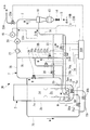
- FIG. 1 is a schematic configuration diagram of a gasification furnace and a slag discharge system showing a first embodiment of the present invention.
- This slag discharge system 1A is used in, for example, an integrated coal gasification combined cycle (IGCC), pulverized coal obtained by pulverizing coal (carbon-containing solid fuel) with a mill or the like together with a gasifying agent such as air or oxygen. It is provided in a gasification furnace 2 that is put into a furnace, pyrolyzed, and gasified.
- IGCC integrated coal gasification combined cycle
- this slag discharge system 1A can be applied not only to a power plant but also to, for example, a gasifier in a chemical plant.
- the gasification furnace 2 is, for example, a pressurized spouted bed type gasification furnace, and includes a substantially cylindrical inner container 2a and a substantially cylindrical outer container 2b concentrically surrounding the inner container 2a. It has. Inside the inner container 2a, a combustor (combustion part) 2c that burns a part of pulverized coal to obtain a heat quantity necessary for a gasification reaction, and a reductor that obtains the heat quantity from the combustor 2c and gasifies the pulverized coal ( Combustion part) 2d is arranged in two upper and lower stages. That is, in the gasification furnace 2, pulverized coal is burned and gasified inside the inner vessel 2a.
- a combustor (combustion part) 2c that burns a part of pulverized coal to obtain a heat quantity necessary for a gasification reaction
- a reductor that obtains the heat quantity from the combustor 2c and gasifies the pulverized coal ( Combustion part)
- a slag hopper 5 is provided at the bottom of the gasification furnace 2, and slag cooling water W is stored therein.
- the slag hopper 5 is partitioned into an inner space 5c positioned inside the inner container 2a and an outer space 5d formed between the outer peripheral surface of the inner container 2a and the inner peripheral surface of the outer container 2b.
- the inner space 5c communicates with a space where the combustor 2c and the reductor 2d are arranged.
- the inner container 2a is provided with a communication hole 5e, and the inner space 5c and the outer space 5d communicate with each other through the communication hole 5e.
- the communication hole 5e is located below the water surface of the slag cooling water W stored in the slag hopper 5 during operation of the gasification furnace 2.
- the slag cooling water W can move in the inner space 5c and the outer space 5d through the communication hole 5e. Thereby, the water surface of the slag cooling water W stored in the inner space 5c and the water surface of the slag cooling water W stored in the outer space 5d are kept constant.
- the ash content in the pulverized coal charged into the gasifier 2 is melted by the combustor 2c, and then stored as liquid molten slag S in the inner space 5c of the slag hopper 5 by gravity from a slag hole (not shown) below the combustor 2c.
- the slag is dropped into the slag cooling water W, solidified by being rapidly cooled and crushed, and discharged out of the gasification furnace 2 by the slag discharge system 1A. That is, the slag S accumulates in the inner space 5c in the slag hopper 5 and hardly accumulates in the outer space 5d.
- the slag discharge system 1A is configured as follows.
- the slag line 7 is connected to the inner space 5c of the slag hopper 5.
- This slag line 7 is connected to the slag cooling water supply line 7A for discharging the slag S crushed from the bottom 5a of the slag hopper 5, one end is connected to the slag cooling water supply line 7A via the slag separation device 10, and the other end is connected.
- a slag cooling water circulation line 7B connected to the slag hopper 5 and a backflow line 7R are provided.
- the upstream end of the slag cooling water supply line 7A is a slag suction port 7p, and the slag suction port 7p is located in the inner space 5c of the slag hopper 5.
- the slag suction port 7p is spaced upward from the bottom 5a of the slag hopper 5 and opens vertically downward.
- Slag slurry S + W which is a mixture of slag S and slag cooling water W in the inner space 5c of the slag hopper 5, is sucked out from the slag suction port 7p.
- a pressure equivalent to the operating pressure of the gasification furnace 2 acts inside the slag line 7.
- the slag separation device 10 connected in the middle of the slag line 7 separates the slag S from the slag slurry.
- a centrifugal separation device liquid cyclone or the like
- a filtration type such as a strainer or a filter
- the separation means may be used.
- the slag slurry sucked out from the slag suction port 7p is transferred to the slag separation device 10 by the water flow flowing through the slag cooling water supply line 7A.
- a lock hopper 13 and a discharge valve 14 are connected to the lower part of the slag separation device 10.
- the lock hopper 13 is a hopper that stores a predetermined amount of the slag S separated from the slag cooling water W by the slag separation device 10, and the discharge valve 14 is periodically opened to discharge the slag.
- the discharged slag S is carried out of the gasification furnace 2 by a transport vehicle (not shown).
- slag cooling water circulation line 7B In the slag cooling water circulation line 7B, a pressure gauge 16, a circulation pump 20, and a cooler 22 are connected in this order on the downstream side of the slag separation device 10.
- the downstream end of the slag cooling water W flow in the normal operation mode (described later) of the slag cooling water circulation line 7B is connected to a reflux portion 5b provided at a height corresponding to the shallow portion of the slag cooling water W in the slag hopper 5.
- the slag line 7 is configured as a loop-shaped pipe line that extends from the inner space 5 c of the slag hopper 5 and is connected again to the reflux portion 5 b in the inner space 5 c of the slag hopper 5.
- the slag cooling water supply line 7A constituting the section from the slag suction port 7p to the slag separation device 10, and the circulation pump 20 to the recirculation part 5b of the slag hopper 5
- the slag cooling water circulation line 7B constituting the section is connected to the downstream side of the circulation pump 20 in a bypass shape by the reverse flow line 7R.
- a water shutoff valve 25 is connected to the downstream side of the slag cooling water feed line 7A connected to the backflow line 7R, and a circulation shutoff valve 26 is connected to the downstream side of the slag cooling water circulation line 7B connected to the backflow line 7R. It is connected.
- a backflow cutoff valve 27 is connected to the backflow line 7R.
- One end of the water supply line 23 is connected to a section adjacent to the slag separation device 10 in the slag cooling water supply line 7A or the slag cooling water circulation line 7B.
- one end of the water supply line 23 (the right end in FIG. 1) is connected to the upstream side of the slag separation device 10 in the slag cooling water supply line 7A.
- the other end (the left end in FIG. 1) of the water supply line 23 is connected to the vicinity of the connection portion to the slag hopper 5 in the slag cooling water circulation line 7B, that is, a section between the circulation cutoff valve 26 and the return portion 5b of the slag hopper 5. ing.
- the slag cooling water W stored in the slag hopper 5 is supplied from the other end of the water supply line 23.
- a water supply valve 28 is connected to the water supply line 23.
- One end (the right end in FIG. 1) of the water supply line 23 may be connected to the upstream side of the slag separation device 10 (section between the water supply shutoff valve 25 and the slag separation device 10) as described above. As indicated by reference numeral 23 a in FIG. 1, it may be connected to the downstream side of the slag separation device 10 (section between the slag separation device 10 and the circulation pump 20).
- water supply line 23 In addition to the water supply line 23, other water supply lines 23 ⁇ / b> A and 23 ⁇ / b> B that can supply external water from outside the slag line 7 may be provided.
- the water supply line 23A is connected to a section between the slag separation device 10 and the circulation pump 20, and a water supply valve 28A is provided.
- the water supply line 23B is a section between the water supply cutoff valve 25 and the slag separation device 10.
- a water supply valve 28B is provided.
- the water supply shutoff valve 25, the circulation shutoff valve 26, the backflow shutoff valve 27, and the water supply valves 28, 28A, 28B may be valves that are manually opened and closed, but in this embodiment, are electrically opened and closed by the control unit 35A.
- the solenoid valve is controlled.
- the selective supply unit DA is constituted by the shut-off valves 25, 26 and 27 described above. This selective supply unit DA selects the slag cooling water W discharged from the circulation pump 20 (or outside water supplied from the water supply lines 23A and 23B) as either the recirculation unit 5b or the slag suction port 7p. Supply is possible.
- an agitation line 7S branched from the section between the circulation pump 20 and the reflux part 5b in the slag cooling water circulation line 7B is connected to the bottom part 5a of the slag hopper 5, and the agitation line 7S includes an agitation line 7S.
- a line valve 30 is connected.
- the agitation line valve 30 is also an electromagnetic valve that is electrically opened and closed by the control unit 35A.
- the slag discharge system 1A configured as described above has three operation modes of “normal operation mode”, “backflow operation mode”, and “stirring operation mode”.
- the control unit 35A causes the slag cooling water W discharged from the circulation pump 20 to flow to the recirculation unit 5b of the slag hopper 5 through only the slag cooling water circulation line 7B without passing through the backflow line 7R and the stirring line 7S.
- the selective supply unit DA and the stirring line valve 30 are operated. That is, as shown in FIG. 2, the water supply cutoff valve 25 and the circulation cutoff valve 26 are opened, and the backflow cutoff valve 27 and the agitation line valve 30 are closed. Further, the water supply valve 28 is also closed.
- a water flow from the slag inlet 7p to the slag separator 10 is formed in the slag line 7, and the slag slurry S + W deposited on the bottom 5a of the slag hopper 5 is sucked from the slag outlet 7p of the slag cooling water supply line 7A.
- the slag separation device 10 is fed out.
- the slag S is separated from the slag cooling water W, stored in the lock hopper 13, periodically discharged from the discharge valve 14, and carried out of the gasifier 2 system. Then, only the slag cooling water W from which the slag S has been removed is sucked and discharged into the circulation pump 20, passes through the slag cooling water circulation line 7B, is further cooled to a predetermined temperature by the cooler 22, and then passes through the recirculation unit 5b and passes through the slag hopper. 5 is returned to the inner space 5c.
- the recirculated slag cooling water W is sucked out from the slag outlet 7p of the slag cooling water supply line 7A together with the slag S accumulated in the bottom 5a of the inner space 5c of the slag hopper 5, and is supplied to the slag separation device 10.
- the control unit 35A operates the selective supply unit DA, the water supply valve 28, and the stirring line valve 30 so that the slag cooling water W discharged from the circulation pump 20 flows toward the reverse flow line 7R. That is, as shown in FIG. 2, the water supply cutoff valve 25, the circulation cutoff valve 26, and the agitation line valve 30 are closed, and the backflow cutoff valve 27 and the water supply valve 28 are opened. If necessary, the water supply valve 28A (28B) of the water supply line 23A (23B) is also opened.
- the slag cooling water W (outside water) discharged from the circulation pump 20 flows back into the slag hopper 5 through the reverse flow line 7R and the slag cooling water supply line 7A.
- the inside of the upstream portion of the slag cooling water supply line 7A is back-washed and purged, slag S is accumulated around the slag suction port 7p, or the slag S remains inside the slag cooling water supply line 7A.
- the slag S is caused to flow back to the slag hopper 5 side by the backflow of the slag cooling water W or the outside water, whereby the blockage of the slag cooling water supply line 7A is suppressed or eliminated.
- the backflow operation can be performed by effectively using the slag cooling water W in the system without drawing any outside water.
- the slag cooling water W stored in the inner space 5c of the slag hopper 5 is extracted in the reverse flow operation mode, there is a possibility that the slag S may be mixed in the slag cooling water W, but the water supply line 23 Since one end of the slag separator 10 is connected to the upstream side of the slag separator 10, the slag cooling water W passes through the slag separator 10 during the reverse flow operation, and then the coarse slag is separated and then supplied to the circulation pump 20. For this reason, it is possible to prevent the circulation pump 20 and the piping (7A, 7B, 7R) from being worn or damaged.
- the gasification furnace 2 and the slag hopper 5 are not newly drilled.
- the other end of the water supply line 23 can be connected to the slag hopper 5 using the existing pipe (7B). For this reason, arrangement
- the control unit 35A allows the selective supply unit DA and the water supply valve 28, the stirring line so that the slag cooling water W discharged from the circulation pump 20 is jetted to the bottom 5a of the slag hopper 5 through the stirring line 7S.
- the valve 30 is operated. That is, as shown in FIG. 2, the water supply cutoff valve 25, the circulation cutoff valve 26, and the backflow cutoff valve 27 are closed, and the water supply valve 28 and the agitation line valve 30 are opened. If necessary, the water supply valve 28A (28B) of the water supply line 23A (23B) is also opened.
- the slag cooling water W (outside water) discharged from the circulation pump 20 is injected from the bottom 5a of the slag hopper 5 through the stirring line 7S.
- the slag S deposited on the bottom 5a of the slag hopper 5 is stirred and diluted to be fluidized and easily sucked from the slag suction port 7p of the slag cooling water feed line 7A, thereby making the slag suction port 7p and the slag cooling water feed line 7A. Can be prevented.
- the reverse flow line 7R is supplied from the slag suction port 7p to the slag separator 10 in the loop-shaped slag line 7 that extends from the slag hopper 5 and is connected to the recirculation part 5b of the slag hopper 5 again. Since it is a single pipe that connects the line 7A and the slag cooling water circulation line 7B from the circulation pump 20 to the recirculation part 5b to the slag hopper 5 in a bypass shape, it can be easily arranged.
- the selective supply unit DA can be configured relatively easily by combining a plurality of shut-off valves 25, 26, and 27 or using a multi-directional valve as in this embodiment. Therefore, there is no concern of complicating the configuration of the slag discharge system 1A.
- the agitation line 7S is also a simple pipe connecting the slag cooling water circulation line 7B and the bottom 5a of the slag hopper 5, and only the agitation line valve 30 is provided between them, so that the configuration of the slag discharge system 1A is complicated. It can be installed without making it.
- the circulation shut-off valve 26 in the selective supply unit DA, the slag cooling water W discharged from the circulation pump 20 or the outside is closed by closing the circulation shut-off valve 26 or reducing the opening when the reverse flow operation mode is executed. Water can be preferentially passed through the backflow line 7R. Thereby, obstruction
- the backflow operation mode and the stirring operation mode are set. It is not necessary to execute for a long time, and the operation of the gasification furnace 2 is not interrupted.
- Switching between the normal operation mode, the reverse flow operation mode, and the stirring operation mode may be performed manually by the operator operating the control unit 35A while monitoring the state of the slag suction port 7p. It is also possible to cause the control unit 35A to automatically switch based on the data of the pressure gauge 16 that measures the pressure.
- the control unit 35A controls the selective supply unit DA and the water supply valve 28 to set the normal operation mode to the reverse flow operation mode, and the inside of the slag cooling water supply line 7A is backwashed purged.
- the blockage of the slag suction port 7p and the slag cooling water supply line 7A is suppressed or eliminated.
- control unit 35A controls the selective supply unit DA, the water supply valve 28, and the agitation line valve 30, and simultaneously with the execution of the reverse flow operation mode or the reverse flow operation mode. Subsequently, the agitation operation mode is executed to agitate and dilute the slag S accumulated on the bottom portion 5a of the slag hopper 5 so that the slag intake port 7p and the slag cooling water supply line 7A are blocked. Can be suppressed or eliminated.
- the pressure gauge 16 is provided on the suction side of the circulation pump 20, the pressure data is input to the control unit 35A, and the selective supply unit DA, the water supply valve 28, and the stirring line valve 30 are controlled by the control unit 35A. Due to the simple configuration, the blockage of the slag inlet 7p and the slag cooling water supply line 7A can be automatically suppressed.
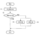
- FIG. 3 is a flowchart showing a flow of operation control of the slag discharge system 1A.
- a pressure measuring process is performed in which the pressure on the suction side of the circulation pump 20 is measured by the pressure gauge 16 and input to the control unit 35A when the gasification furnace 2 is started and after the operation is started (step S35).
- step S1 a blockage determination step for determining the blockage state of the slag intake port 7p based on the input pressure data is executed (step S2).
- the control returns to the original, and the pressure measurement step S1 and blockage determination step S2 are repeated. Further, when it is determined in the blockage determination step S2 that the slag suction port 7p is blocked or there is a sign of blockage, that is, when the pressure on the suction side of the circulation pump 20 reaches a predetermined threshold value, Either or both of the process (step S3) and the stirring process (step S4) are performed.
- the execution time of the backflow process S3 and the stirring process S4 may be short. Thereby, as mentioned above, obstruction
- a pressure measurement step S1 for measuring the pressure on the suction side of the circulation pump 20 and a blockage determination step S2 for determining the blockage state of the slag suction port 7p based on the pressure data measured in the pressure measurement step S1;
- the reverse flow step S3 and the agitation step S4 are executed when it is determined in the blockage determination step S2 that the slag suction port 7p is blocked, or when it is determined that there is a sign of blockage.
- the blockage of the slag inlet 7p and the slag cooling water supply line 7A can be automatically suppressed or eliminated with a simple configuration.
- the slag S in the slag hopper 5 is agitated periodically and instantaneously to agitate the slag S in the slag hopper 5.
- the slag suction port 7p and the slag cooling water supply line 7A can be prevented from being blocked.
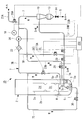
- FIG. 4 is a schematic configuration diagram of a gasification furnace and a slag discharge system showing a second embodiment of the present invention.
- This slag discharge system 1B basically has the same configuration as the slag discharge system 1A of the first embodiment, but a plurality of (for example, two) slag pots 5A, 5B in the inner space 5c of the slag hopper 5.
- the upstream section of the slag cooling water supply line 7A, the downstream section of the backflow line 7R, and the downstream section of the stirring line 7S are branched into a plurality. Since each part to which the same reference numerals as those in FIG. 1 are given has the same configuration as that of the first embodiment, a duplicate description is omitted.
- the upstream section of the slag cooling water supply line 7A is branched into two water supply branch lines 7Aa and 7Ab connected to the two slag pots 5A and 5B, respectively.
- 7 pb is provided.
- Water supply cutoff valves 25a and 25b are connected to these two water supply branch lines 7Aa and 7Ab, respectively.
- the downstream section of the backflow line 7R branches into two backflow branch lines 7Ra and 7Rb connected to the two water supply branch lines 7Aa and 7Ab, respectively, and backflow shut-off valves 27a and 27b are connected to each of them. ing.
- the point that the circulation cutoff valve 26 is connected to the slag cooling water circulation line 7B is the same as that of the first embodiment.
- the selective supply unit DB is constituted by the shut-off valves 25a, 25b, 26, 27a, 27b and the backflow branch lines 7Ra, 7Rb.
- the selective supply unit DB enables the slag cooling water W (outside water) discharged from the circulation pump 20 to be selectively supplied to either the recirculation unit 5b or the slag suction ports 7pa and 7pb and backflow.
- the slag cooling water W (outside water) supplied from the line 7R is selectively supplied to the plurality of water supply branch lines 7Aa and 7Ab.
- the shutoff valves 25a, 25b, 26, 27a, 27b and the water supply valves 28, 28A, 28B may be valves that are manually opened / closed. In this embodiment, the solenoid valves are electrically controlled to be opened / closed by the control unit 35B. It is said that.
- the downstream section of the agitation line 7S branches into two agitation branch lines 7Sa and 7Sb connected to the bottoms 5a of the two slag pots 5A and 5B, respectively.
- 30b is connected.
- These agitation line valves 30a and 30b are also shut-off valves that are electrically controlled to be opened and closed by the control unit 35B.
- the slag cooling water W (outside water) supplied from the agitation line 7S is supplied to a plurality of agitation branch lines 7Sa and 7Sb. Is a valve that selectively supplies to the valve.
- the slag discharge system 1B configured as described above has a “normal operation mode”, “reverse flow operation mode”, “stirring operation mode” as shown in the chart of FIG. ”Has three operation modes.
- the control unit 35B does not allow the slag cooling water W discharged from the circulation pump 20 to pass through the slag cooling water circulation line 7B but through the slag cooling water circulation line 7B without passing through the backflow line 7R and the agitation line 7S (slag pots 5A, 5B).
- the selective supply unit DB and the agitation line valves 30a and 30b are operated so as to flow to the reflux unit 5b. That is, as shown in FIG. 5, one of the water supply cutoff valves 25a and 25b is opened and the other is closed, the circulation cutoff valve 26 is opened, and the backflow cutoff valves 27a and 27b and the agitation line valves 30a and 30b are closed. . Further, the water supply valve 28 is also closed.
- a water flow from the slag inlet 7pa or 7pb to the slag separator 10 is formed in the water supply branch line 7Aa or 7Ab in which the water supply shutoff valves 25a and 25b are open, and the bottom 5a of the slag pot 5A or 5B.
- the slag slurry S + W deposited on the slag is sucked out from the slag suction port 7pa or 7pb and fed to the slag separation device 10.
- the slag cooling water W from which the slag S has been separated by the slag separator 10 is returned to the slag pots 5A and 5B through the slag cooling water circulation line 7B and the return part 5b.
- the control unit 35B selects the selective supply unit DB and the agitation line valves 30a and 30b so that the slag cooling water W discharged from the circulation pump 20 passes through the reverse flow branch line 7Ra or 7Rb of the reverse flow line 7R.
- the water supply valve 28 is operated. That is, as shown in FIG. 5, the water shutoff valves 25a and 25b, the circulation shutoff valve 26, and the agitation line valves 30a and 30b are closed, and one of the backflow shutoff valves 27a and 27b is opened and the other is closed. Valve 28 is opened.
- the slag cooling water W discharged from the circulation pump 20 passes through the backflow branch line 7Ra or 7Rb of the backflow line 7R, and further flows back to the slag pot 5A or 5B through the water supply branch line 7Aa or 7Ab.
- the slag cooling water W stored in the slag hopper 5 is supplied from the water supply line 23 to the suction side of the circulation pump 20.
- one slag pot 5A is used, and the other slag pot 5B is set in a standby state (the reverse is also possible). That is, the water supply cutoff valve 25a is opened and the water supply cutoff valve 25b is closed.
- the selective supply unit DB When performing this switching operation, the selective supply unit DB is operated to temporarily flow the slag cooling water W or the outside water discharged from the circulation pump 20 from the reverse flow line 7R to the other water supply branch line 7Ab.
- the inside of the water supply branch line 7Ab is back-washed and purged toward the slag pot 5B. That is, the mode is temporarily switched to the reverse flow operation mode.
- the water feed branch lines 7Aa and 7Ab are purged back-washing, thereby performing the gasification furnace 2 Can be operated continuously without interruption.
- the control unit 35B causes the slag cooling water W discharged from the circulation pump 20 to be injected to the bottom 5a of the slag pot 5A or 5B via either the agitation branch line 7Sa or 7Sb of the agitation line 7S.
- the selective supply unit DB, the agitation line valves 30a and 30b, and the water supply valve 28 are operated. That is, as shown in FIG. 5, the water supply shutoff valves 25a and 25b, the circulation shutoff valve 26, and the reverse flow shutoff valves 27a and 27b are closed, and one of the agitation line valves 30a and 30b is opened and the other is closed. Valve 28 is opened.
- the slag cooling water W discharged from the circulation pump 20 and the outside water supplied from the water supply lines 23A and 23B are injected to the bottom 5a of the slag pot 5A or 5B via the stirring branch line 7Sa or 7Sb.
- the reverse flow operation mode for performing the backwash purge of the water supply branch lines 7Aa and 7Ab using the reverse flow line 7R is executed.
- the agitation operation mode is executed in which the slag cooling water W discharged from the circulation pump 20 is injected from the plurality of agitation branch lines 7Sa, 7Sb to the bottoms 5a of the slag pots 5A, 5B. be able to.
- the slag S deposited on the bottom 5a of the slag pots 5A and 5B is stirred and diluted to be fluidized and easily sucked from the slag outlets 7pa and 7pb of the water supply branch lines 7Aa and 7Ab. Can be prevented.
- Switching between the normal operation mode and the reverse flow operation mode and the agitation operation mode may be performed manually. However, as in the case of the slag discharge system 1A of the first embodiment, based on the data of the pressure gauge 16. Then, the control unit 35B may be automatically switched.
- FIG. 6 is a schematic configuration diagram of a gasification furnace and a slag discharge system showing a third embodiment of the present invention.
- This slag discharge system 1C has a point that a plurality of slag suction ports 7pc and 7pd are provided for a single slag hopper 5, and a connection portion 7Sc to the bottom 5a of the inner space 5c of the slag hopper 5 in the stirring line 7S. It is different from the slag discharge system 1A of the first embodiment in that it is branched and connected to a plurality of points, and is the same in other points. Therefore, the same reference numerals are assigned to the same components and the description thereof is omitted.
- the slag cooling water supply line 7A constituting the upstream portion of the slag line 7 is branched into, for example, two water supply branch lines 7Ac and 7Ad toward the slag hopper 5, and slag suction ports 7pc and 7pd are provided at the respective ends. Is provided.
- the two water supply branch lines 7Ac and 7Ad merge into one before the connection with the reverse flow line 7R.
- the slag slurry S + W accumulated on the bottom 5a of the slag hopper 5 is sucked out uniformly from the two slag suction ports 7pc and 7pd, and the two water supply branch lines 7Ac and 7Ad and the slag cooling It is fed to the slag separator 10 via the water feed line 7A. Further, when the backflow operation mode is executed, the slag cooling water W and the outside water supplied from the backflow line 7R are evenly distributed to the two water supply branch lines 7Ac and 7Ad.
- the ratio of the suction areas of the slag suction ports 7pc and 7pd to the planar area of the slag hopper 5 increases. For this reason, the probability that the slag inlets 7pc and 7pd are blocked by the slag S can be reduced, or the time until the slag can be closed can be extended, and the frequency of executing the reverse flow operation mode and the stirring operation mode can be reduced.
- the carrying-out property of S can be improved.
- connection part 7Sc to the bottom part 5a of the slag hopper 5 of the stirring line 7S is branched into, for example, three.
- the slag S accumulated on the bottom portion 5a of the slag hopper 5 is more widely stirred and fluidized when the agitation operation mode is executed, and the slag suction ports 7pc, 7pd and the slag cooling water supply line 7A (water supply) Blockage of the branch lines 7Ac, 7Ad) can be suppressed or eliminated.
- FIG. 7 is a schematic configuration diagram of a gasification furnace and a slag discharge system showing a fourth embodiment of the present invention.
- This slag discharge system 1D has basically the same configuration as the slag discharge system 1A of the first embodiment, but the water supply line 23b is connected to the slag hopper 5 and the slag cooling water circulation line 7B. And the point by which the inflow cutoff valve 29 is provided in the gasification furnace 2 side rather than the connection position with the backflow line 7R in 7A of slag cooling water water supply lines differs.
- symbol is attached
- the upstream end of the slag cooling water W flow in the reverse flow operation mode passes through the outer container 2 b and communicates with the outer space 5 d of the slag hopper 5.
- the downstream end of the slag cooling water W flow in the reverse flow operation mode of the water supply line 23b is connected to a section between the slag separation device 10 and the circulation pump 20 in the slag cooling water circulation line 7B.
- the inflow shut-off valve 29 is provided on the gasification furnace 2 side (that is, on the upstream side of the slag cooling water W flow in the normal operation mode) from the connection position with the reverse flow line 7R. Is provided.
- the control unit (switching means) 35 ⁇ / b> C in the present embodiment controls each valve and the opening degree of the inflow cutoff valve 29. In the normal operation mode, the reverse flow operation mode, and the stirring operation mode, the inflow shutoff valve 29 is controlled to be in an open state.
- the slag discharge system 1D has a “separator cleaning mode” in addition to the “normal operation mode”, “backflow operation mode”, and “stirring operation mode”.
- the normal operation mode, the backflow operation mode, and the agitation operation mode are substantially the same as those in the first embodiment, and thus the description of the same contents is omitted.
- the reverse flow operation mode and the stirring operation mode in the present embodiment are different from the first embodiment in that the slag cooling water W is supplied to the circulation pump 20 through the water supply line 23b.
- the slag cooling water W is extracted from the outer space 5d in the slag hopper 5 where the slag S hardly exists, and the injected slag cooling water W is downstream of the slag separation device 10 (slag slag In the section between the separator 10 and the circulation pump 20, the slag cooling water circulation line 7B flows.
- the slag cooling water W containing almost no slag S can be supplied to the circulation pump 20 without going through the slag separation device 10 in the reverse flow operation mode and the stirring operation mode. Since the slag cooling water W containing almost no slag S can be supplied to the circulation pump 20 without going through the slag separator 10, the reverse flow operation mode and the The stirring operation mode can be performed, and wear and damage of the circulation pump 20 and piping due to the slag S can be prevented.
- the control unit 35C selects and supplies the slag cooling water (fluid) W discharged from the circulation pump 20 to the slag separation device 10 via the backflow line 7R.
- the DA, the water supply valve 28, the stirring line valve 30 and the inflow shutoff valve 29 are operated. That is, the circulation cutoff valve 26, the agitation line valve 30, and the inflow cutoff valve 29 are closed, and the backflow cutoff valve 27, the water supply valve 28, and the water supply cutoff valve 25 are opened. If necessary, the water supply valve 28A (28B) of the water supply line 23A (23B) is also opened.
- the slag cooling water W extracted from the outer space 5d of the slag hopper 5 is supplied to the circulation pump 20 without passing through the slag separation device 10.
- the slag cooling water W (and / or outside water) discharged from the circulation pump 20 is supplied to the slag separation device 10 via the backflow line 7R and the slag cooling water feed line 7A.
- the slag cooling water W containing almost no slag S can be supplied to the slag separator 10 without going through the slag separator 10.
- the separation device cleaning mode is preferably performed when the slag S is clogged in the slag separation device 10 or when there is a sign of the clogging, but may be performed every predetermined time. Further, it may be determined based on the pressure value measured by the pressure gauge 16 whether the slag S is clogged in the slag separation device 10 or whether there is a sign of clogging.
- the slag cooling water W that has flowed into the slag cooling water supply line 7A from the backflow line 7R is supplied to the slag suction port 7p (backflow operation mode) or supplied to the slag separation device 10 ( The separation device washing mode) is switched by the water supply shutoff valve 25 and the inflow shutoff valve 29.
- a three-way valve is provided at the connection portion between the backflow line 7R and the slag cooling water feed line 7A. The supply destination may be switched.
- the gasification furnace 2 has a simple configuration.
- the slag inlets 7p, 7pa to 7pd for sucking out the slag S from the bottom of the slag are prevented or eliminated from being blocked by the slag S, and the operation of the gasification furnace 2 can be performed smoothly.
- the control units 35A to 35C used in the first to fourth embodiments are, for example, CPU (Central A processing unit (RAM), a random access memory (RAM), a read only memory (ROM), and a computer-readable storage medium.
- a series of processes for realizing various functions is stored in a storage medium or the like in the form of a program as an example, and the CPU reads the program into a RAM or the like to execute information processing / arithmetic processing.
- the program is preinstalled in a ROM or other storage medium, provided in a state stored in a computer-readable storage medium, or distributed via wired or wireless communication means. Etc. may be applied.
- the computer-readable storage medium is a magnetic disk, a magneto-optical disk, a CD-ROM, a DVD-ROM, a semiconductor memory, or the like.
- the selective supply parts DA and DB are each comprised from several cutoff valve 25,25a, 25b, 26,27,27a, 27b, several cutoff valve is changed to a three-way change or a four-way valve. It is good also as a structure put together by multi-way valves, such as.
- the two agitation line valves 30a and 30b in the second embodiment may be replaced with one three-way valve.
Landscapes
- Chemical & Material Sciences (AREA)
- Engineering & Computer Science (AREA)
- Combustion & Propulsion (AREA)
- Oil, Petroleum & Natural Gas (AREA)
- Organic Chemistry (AREA)
- Gasification And Melting Of Waste (AREA)
Abstract
ガス化炉(2)の底部にてスラグ冷却水Wを貯留し、スラグ(S)を受容するスラグホッパ(5)と、スラグホッパ(5)の底部からスラグ(S)とスラグ冷却水(W)とを吸い出してスラグ分離装置(10)に送るスラグ吸出口(7p)およびスラグ冷却水送水ライン(7A)と、スラグ(S)を吸い出す水流を形成する循環ポンプ(20)と、スラグ分離装置(10)からスラグホッパ(5)に繋がるスラグ冷却水循環ライン(7B)と、循環ポンプ(20)から吐出されたスラグ冷却水(W)をスラグ冷却水送水ライン(7A)に逆流させる逆流ライン(7R)と、循環ポンプ(20)から吐出されたスラグ冷却水(W)をスラグ冷却水循環ライン(7B)と逆流ライン(7R)とに選択的に供給可能にする選択供給部(DA)と、スラグ冷却水送水ライン(7A)に一端が接続された水供給ライン(23)と、を備える。
Description
本発明は、石炭等の炭素含有固体燃料を熱分解させてガス化するガス化炉のスラグ排出システム、これを備えたガス化炉、およびスラグ排出システムの運転方法に関する。
石炭、木質ペレット等のバイオマス燃料、ペットコーク等の炭素含有固体燃料を熱分解することより可燃性ガスを生成するガス化炉では、炭素含有固体燃料の灰分が溶融し、スラグとしてガス化炉の底部に設けられたスラグホッパに堆積する。スラグホッパにはスラグ冷却水が貯留されており、スラグはこのスラグ冷却水中に落下して急冷されることにより固化し、破砕される。
このように固化・破砕されてスラグホッパ内に溜まったスラグは、ガス化炉の外部に設けられたロックホッパを経てガス化炉の系外へと排出される。スラグはスラグ冷却水に比べて密度が大きいため、従来はスラグホッパからロックホッパへスラグを移動させる際、重力により自然落下させていた。例えば、特許文献1に、ガス化炉の下方にロックホッパを配置したスラグ排出システムが開示されている。
ところが、上述したスラグ排出システムによれば、ガス化炉の下方にロックホッパを設けるためにガス化炉の配置位置が高くなる。したがって、プラントの設置面からガス化炉上部までの高さが増すこととなる。ガス化炉の配置位置が高くなることにより、ガス化炉を支持する支持架台や操作架台などの配置位置が高くなる。
そこで、特許文献2に開示されているようなスラグ排出システムが提案されている。このスラグ排出システムでは、ロックホッパをガス化炉の側方に配置し、ガス化炉底部のスラグホッパからロックホッパへと連通するスラグ排出ラインを設け、循環ポンプによってスラグ排出ライン中にスラグホッパからロックホッパへの水流を形成し、この水流によってスラグホッパ内のスラグをロックホッパへ排出するようにしている。
こうすることにより、スラグをスラグ冷却水の流れに乗せてスラグホッパからロックホッパに移送することができるため、ロックホッパをガス化炉の側方に配置することが可能となり、プラントの設置面からガス化炉上部までの高さを低く抑えることができる。
上記のように、特許文献2に示される従来のスラグ排出システムでは、ガス化炉底部のスラグホッパに落下したスラグを、スラグホッパに貯留されたスラグ冷却水と共にスラグ排出ラインで吸い出している。スラグホッパからスラグを吸い出すスラグ排出ラインのスラグ吸出口は、鉛直下方を向いてスラグホッパの底面に向かって開口している。
ガス化炉の通常運転時は、スラグホッパ内に落下するスラグが順次スラグ排出ラインのスラグ吸出口から吸い出されて排出されるため、スラグ吸出口にスラグが堆積することはない。しかし、ガス化炉の起動時や一時的な運転停止後にはスラグ吸出口の上までスラグが堆積した状態となることがある。この状態でスラグ排出ラインからのスラグ吸い出しを再開した場合、スラグの密度が高過ぎてスラグ排出ラインが詰まり、閉塞してしまう懸念がある。また、スラグ排出ライン内に残存するスラグによってスラグ排出ラインが閉塞してしまう懸念もある。このように、スラグ排出ラインを閉塞させる事象は、主にスラグ排出システムの起動時に起こりやすく、そうなるとガス化炉の運転に支障を来す。
本発明は、上記の課題を解決するためになされたものであり、簡素な構成により、ガス化炉の底部からスラグを吸い出すスラグ吸出口がスラグによって閉塞することを抑制または解消し、ガス化炉の運転を順調に行うことのできるスラグ排出システム、これを備えたガス化炉、およびスラグ排出システムの運転方法を提供することを目的とする。
上記課題を解決するため、本発明は、以下の手段を採用する。
即ち、本発明の第1態様に係るスラグ排出システムは、炭素含有固体燃料をガス化するガス化炉の底部に設けられ、前記炭素含有固体燃料から生じたスラグを受容するとともに、該スラグを急冷するスラグ冷却水が貯留されたスラグホッパと、前記スラグホッパの底部に堆積する前記スラグを前記スラグ冷却水と共に吸い出すスラグ吸出口と、前記スラグ吸出口から吸い出された前記スラグと前記スラグ冷却水とを前記スラグホッパの外部に搬送するスラグ冷却水送水ラインと、前記スラグ冷却水送水ラインに接続され、前記スラグ冷却水に含まれる前記スラグを分離するスラグ分離装置と、前記スラグ分離装置から前記スラグホッパに前記スラグ冷却水を循環させるスラグ冷却水循環ラインと、前記スラグ冷却水循環ラインに接続され、前記スラグ吸出口から前記スラグと前記スラグ冷却水とを吸い出す水流を形成する循環ポンプと、一端が前記スラグ冷却水送水ラインに接続され、他端が前記スラグ冷却水循環ラインにおける前記循環ポンプの下流側との間に接続された逆流ラインと、前記循環ポンプから吐出された前記スラグ冷却水を、前記スラグ冷却水循環ラインと前記逆流ラインとに選択的に供給可能にする選択供給部と、前記スラグ冷却水送水ラインまたは前記スラグ冷却水循環ラインにおける、前記スラグ分離装置に隣接する区間に一端が接続された水供給ラインと、前記水供給ラインに設けられた水供給弁と、を備えている。
即ち、本発明の第1態様に係るスラグ排出システムは、炭素含有固体燃料をガス化するガス化炉の底部に設けられ、前記炭素含有固体燃料から生じたスラグを受容するとともに、該スラグを急冷するスラグ冷却水が貯留されたスラグホッパと、前記スラグホッパの底部に堆積する前記スラグを前記スラグ冷却水と共に吸い出すスラグ吸出口と、前記スラグ吸出口から吸い出された前記スラグと前記スラグ冷却水とを前記スラグホッパの外部に搬送するスラグ冷却水送水ラインと、前記スラグ冷却水送水ラインに接続され、前記スラグ冷却水に含まれる前記スラグを分離するスラグ分離装置と、前記スラグ分離装置から前記スラグホッパに前記スラグ冷却水を循環させるスラグ冷却水循環ラインと、前記スラグ冷却水循環ラインに接続され、前記スラグ吸出口から前記スラグと前記スラグ冷却水とを吸い出す水流を形成する循環ポンプと、一端が前記スラグ冷却水送水ラインに接続され、他端が前記スラグ冷却水循環ラインにおける前記循環ポンプの下流側との間に接続された逆流ラインと、前記循環ポンプから吐出された前記スラグ冷却水を、前記スラグ冷却水循環ラインと前記逆流ラインとに選択的に供給可能にする選択供給部と、前記スラグ冷却水送水ラインまたは前記スラグ冷却水循環ラインにおける、前記スラグ分離装置に隣接する区間に一端が接続された水供給ラインと、前記水供給ラインに設けられた水供給弁と、を備えている。
前記構成のスラグ排出システムによれば、循環ポンプから吐出されたスラグ冷却水がスラグ冷却水循環ラインを通ってスラグホッパに流れるように選択供給部を操作すれば、スラグ冷却水送水ライン中に、スラグ吸出口からスラグ分離装置への水流が形成される。このため、スラグホッパの底部に堆積したスラグがスラグ冷却水と共にスラグ吸出口から吸い出されてスラグ冷却水送水ラインを経てスラグ分離装置に送給され、スラグ排出システムは通常運転モードとなる。
また、循環ポンプから吐出されたスラグ冷却水が逆流ライン側に流れるように選択供給部を操作すれば、循環ポンプから吐出されたスラグ冷却水が、逆流ラインとスラグ冷却水送水ラインとを経てスラグホッパ内に逆流し、スラグ排出システムは逆流運転モードとなる。このため、スラグ冷却水送水ラインの上流側部分の内部が逆洗パージされる。
したがって、スラグ吸出口の周囲にスラグが堆積していたり、スラグ冷却水送水ラインの内部にスラグが残留していても、この残留したスラグがスラグ冷却水の逆流によってスラグホッパ側に流し戻され、これによってスラグ吸出口およびスラグ冷却水送水ラインの閉塞を抑制または解消することができる。
逆流運転モードにおいては、水供給弁を開くことにより、スラグ冷却水送水ラインまたはスラグ冷却水循環ラインにおける、スラグ分離装置に隣接する区間に水供給ラインから水が供給される。この水としては、スラグホッパに貯留されたスラグ冷却水、あるいは系外から導入される外水が考えられる。このため、循環ポンプの吸込み側が真空になることを防止し、循環ポンプから吐出された水を逆流ラインからスラグ冷却水送水ライン側に逆流させてスラグ吸出口およびスラグ冷却水送水ラインの閉塞を確実に解消することができる。
逆流ラインは、スラグ冷却水送水ラインにおけるスラグ吸出口からスラグ分離装置までの区間と、スラグ冷却水循環ラインにおける循環ポンプの下流側との間をバイパス的に接続する1本の配管であるため、容易に配設することができる。また、選択供給部は、複数の遮断弁を組み合わせたり、多方向弁を用いたりすることによって比較的容易に構成することができる。しかも、逆流ラインを用いたスラグ冷却水送水ラインの逆洗パージは短時間で完了するため、逆流運転モードを長時間に亘って実行する必要はなく、ガス化炉の運転を中断させることはない。
前記構成のスラグ排出システムにおいて、前記水供給ラインは、その他端から前記スラグホッパに貯留された前記スラグ冷却水が供給される構成としてもよい。
こうすれば、逆流運転時に水供給弁を開くことにより、スラグホッパに貯留されたスラグ冷却水が水供給ラインを経て循環ポンプに供給される。これにより、系外から外水を引くことなく、系内のスラグ冷却水を有効に利用して逆流運転を行うことができる。
こうすれば、逆流運転時に水供給弁を開くことにより、スラグホッパに貯留されたスラグ冷却水が水供給ラインを経て循環ポンプに供給される。これにより、系外から外水を引くことなく、系内のスラグ冷却水を有効に利用して逆流運転を行うことができる。
上記のように水供給ラインからスラグホッパに貯留された前記スラグ冷却水が供給されたスラグ排出システムにおいて、前記水供給ラインの前記一端を前記スラグ分離装置の下流側に接続してもよい。
こうすれば、スラグ分離装置が故障等により停止した場合にも逆流運転を行うことができる。
こうすれば、スラグ分離装置が故障等により停止した場合にも逆流運転を行うことができる。
上記のように水供給ラインからスラグホッパに貯留された前記スラグ冷却水が供給されたスラグ排出システムにおいて、前記水供給ラインの前記一端を前記スラグ分離装置の上流側に接続してもよい。
こうすれば、逆流運転時にスラグホッパに貯留されたスラグ冷却水がスラグ分離装置を通過することによって粗粒スラグを分離されてから循環ポンプに供給される。このため、循環ポンプおよび配管類の摩耗や損傷を防止することができる。
こうすれば、逆流運転時にスラグホッパに貯留されたスラグ冷却水がスラグ分離装置を通過することによって粗粒スラグを分離されてから循環ポンプに供給される。このため、循環ポンプおよび配管類の摩耗や損傷を防止することができる。
前記水供給ラインは、その前記他端が前記スラグ冷却水循環ラインにおける前記スラグホッパへの接続部付近に合流するように接続してもよい。
こうすれば、水供給ラインの他端をスラグホッパに接続するにあたり、ガス化炉およびスラグホッパに新たに穿孔することなく、既存の配管を利用して接続することができる。このため、水供給ラインの配設が容易になる。
こうすれば、水供給ラインの他端をスラグホッパに接続するにあたり、ガス化炉およびスラグホッパに新たに穿孔することなく、既存の配管を利用して接続することができる。このため、水供給ラインの配設が容易になる。
前記構成のスラグ排出システムにおいて、前記ガス化炉は、前記炭素含有固体燃料を燃焼してガス化する燃焼部を有し、前記スラグホッパは、前記燃焼部と連通する内側空間を内部に有する内側容器及び該内側容器を覆う外側容器を有し、前記水供給ラインの前記他端は、前記内側容器と前記外側容器との間の外側空間に位置していてもよい。
燃焼部で炭素含有固体燃料が燃焼した際に生成されるスラグは、燃焼部と連通する内側空間へ供給される。これにより、内側空間と内側容器によって隔てられている外側空間にはほとんどスラグが存在しない。
上記構成では、水供給ラインの他端が外側空間に位置し、外側空間に貯留されたスラグ冷却水が水供給ラインに供給されている。これにより、水供給ラインの一端をスラグ分離装置の下流側に接続しても、スラグがほとんど含まれていないスラグ冷却水を循環ポンプに供給することができる。このように、スラグ分離装置を介さずに、スラグのほとんど含まれていないスラグ冷却水を循環ポンプに供給することができるので、スラグ分離装置が故障等により停止した場合にも逆流運転を行うことができ、且つ、スラグによる循環ポンプおよび配管類の摩耗や損傷を防止することができる。
上記構成では、水供給ラインの他端が外側空間に位置し、外側空間に貯留されたスラグ冷却水が水供給ラインに供給されている。これにより、水供給ラインの一端をスラグ分離装置の下流側に接続しても、スラグがほとんど含まれていないスラグ冷却水を循環ポンプに供給することができる。このように、スラグ分離装置を介さずに、スラグのほとんど含まれていないスラグ冷却水を循環ポンプに供給することができるので、スラグ分離装置が故障等により停止した場合にも逆流運転を行うことができ、且つ、スラグによる循環ポンプおよび配管類の摩耗や損傷を防止することができる。
前記構成のスラグ排出システムにおいて、前記選択供給部は、前記スラグ冷却水送水ラインにおける前記逆流ラインの接続部よりも下流側に設けられた送水遮断弁と、前記逆流ラインに設けられた逆流遮断弁と、を備えて構成してもよい。
選択供給部を上記構成とすることにより、送水遮断弁を開いて逆流遮断弁を閉じれば通常運転モードとなり、送水遮断弁を閉じて逆流遮断弁を開けば逆流運転モードとなる。本構成により、選択供給部を簡素で信頼性の高い構成とすることができる。
前記選択供給部は、前記スラグ冷却水循環ラインにおける前記逆流ラインの接続部よりも下流側に設けられた循環遮断弁をさらに備えていてもよい。
選択供給部を上記構成とすれば、逆流運転モードの実行時に循環遮断弁を閉じる、または開度を小さくすることにより、循環ポンプから吐出されたスラグ冷却水または外水を逆流ラインに優先的に流すことができる。これにより、スラグ吸出口およびスラグ冷却水送水ラインの閉塞を確実且つ迅速に解消することができる。
前記スラグ冷却水送水ラインには、前記逆流ラインから流入する流体を前記スラグ吸出口側に送るか前記スラグ分離装置側に送るかを切換える切換え手段が設けられていてもよい。
上記構成のように、スラグ冷却水送水ラインに切換え手段を設ければ、切換え手段を切換えることで、逆流ラインからスラグ冷却水送水ラインに流入する流体(例えば、スラグ冷却水や外水)をスラグ吸出口に供給するかスラグ分離装置に供給するかを選択することができる。
したがって、スラグ吸出口の周囲にスラグが堆積していたり、スラグ冷却水送水ラインの内部にスラグが残留していた場合に、逆流ラインを流通する流体をスラグ吸出口に供給するように、切換え手段を切換えれば、スラグ吸出口に供給される流体によって残留したスラグがスラグホッパ側に流し戻され、これによってスラグ吸出口およびスラグ冷却水送水ラインの閉塞を抑制または解消することができる。
また、スラグ分離装置の内部でスラグにより閉塞が発生した場合には、逆流ラインを流通する流体をスラグ分離装置に供給するように、切換え手段を切換えれば、スラグ分離装置に供給される流体によって閉塞の要因となっているスラグが押し流され、スラグ分離装置の内部の閉塞を解消することができる。
したがって、スラグ吸出口の周囲にスラグが堆積していたり、スラグ冷却水送水ラインの内部にスラグが残留していた場合に、逆流ラインを流通する流体をスラグ吸出口に供給するように、切換え手段を切換えれば、スラグ吸出口に供給される流体によって残留したスラグがスラグホッパ側に流し戻され、これによってスラグ吸出口およびスラグ冷却水送水ラインの閉塞を抑制または解消することができる。
また、スラグ分離装置の内部でスラグにより閉塞が発生した場合には、逆流ラインを流通する流体をスラグ分離装置に供給するように、切換え手段を切換えれば、スラグ分離装置に供給される流体によって閉塞の要因となっているスラグが押し流され、スラグ分離装置の内部の閉塞を解消することができる。
前記選択供給部および前記水供給弁を制御する制御部をさらに備えた構成としてもよい。これにより、通常運転モードと逆流運転モードの切り替えを自動的に行うことができる。
前記構成のスラグ排出システムにおいて、前記循環ポンプの吸い込み側の圧力を測定する圧力計をさらに備え、前記制御部は、前記圧力計により測定された圧力データが所定の閾値を超えた時に、前記循環ポンプから吐出された前記スラグ冷却水が前記逆流ラインを経て前記スラグホッパに流れるように前記選択供給部を制御する制御部と、をさらに備えた構成としてもよい。
ガス化炉の起動時、あるいは運転中(通常運転モード)において、スラグ吸出口の周囲やスラグ冷却水送水ラインの内部にスラグが堆積して閉塞気味になると、循環ポンプの吸込み側の圧力が低くなる。この圧力データが所定の閾値を超えると、制御部が選択供給部を制御し、これによって循環ポンプから吐出されたスラグ冷却水が逆流ラインを経てスラグホッパに逆流する逆流運転モードとなる。このため、スラグの堆積によるスラグ吸出口およびスラグ冷却水送水ラインの閉塞が抑制または解消される。
このようにすれば、循環ポンプの吸い込み側に圧力計を設け、その負圧データを制御部に入力して制御部に選択供給部を制御させるという簡素な構成により、スラグ吸出口およびスラグ冷却水送水ラインの閉塞を自動的に抑制または解消することができる。
前記構成のスラグ排出システムにおいて、前記スラグホッパは、その内部に複数のスラグポットが並設され、前記スラグ吸出口は複数の前記スラグポットに対応して複数設けられ、前記スラグ冷却水送水ラインの上流側区間は複数の前記スラグ吸出口に各々接続される複数の送水分岐ラインに分岐され、前記選択供給部は、前記逆流ラインから供給される前記スラグ冷却水または外水を、複数の前記送水分岐ラインに選択的に供給可能な構成としてもよい。
上記構成によれば、スラグ排出システムの通常運転モードにおいては一方のスラグポットを使用し、他方のスラグポットを待機状態にしておく。そして、所定の運転時間が経過し、一方のスラグポットからスラグを吸い出す一方の送水分岐ラインがスラグにより閉塞気味になったら、この一方のスラグポットを待機状態とし、他方のスラグポットのスラグを他方の送水分岐ラインで吸い出すように選択供給部を切り替え操作する。
この切り替え操作を行う際に、選択供給部を操作して、循環ポンプから吐出されたスラグ冷却水を逆流ラインから他方の送水分岐ラインに一時的に流し、他方の送水分岐ラインの内部をスラグポットに向かって逆洗パージする。即ち、一時的に逆流運転モードに切り替える。
これにより、待機状態にあった他方の送水分岐ラインの内部にスラグが堆積または残留していても、この残留したスラグをスラグポット側に流し戻し、送水分岐ラインの閉塞の可能性を排除した上で、この送水分岐ラインにより他方のスラグポットのスラグを吸い出させて通常運転を続行することができる。他方のスラグポットから一方のスラグポットに運転を切り替える時も同様に送水分岐ラインの逆洗パージを行う。
このように、複数のスラグポットを交代で使用し、その交代時に先駆けて一時的に逆流運転モードに切り替えて送水分岐ラインの逆洗パージを行うことにより、ガス化炉の運転を中断させることなく、スムーズに連続運用することができる。
前記構成のスラグ排出システムにおいて、前記スラグ吸出口は、単一の前記スラグホッパに対して複数設けてもよい。こうすれば、スラグホッパの平面面積に対するスラグ吸出口の吸い込み面積の割合が多くなるため、スラグによってスラグ吸出口が閉塞してしまう確率を低下させる、あるいは閉塞するまでの時間を延ばすことができる。
前記構成のスラグ排出システムにおいて、前記スラグ冷却水循環ラインから分岐して前記スラグホッパの底部に接続される撹拌ラインと、前記撹拌ラインに接続された撹拌ライン弁と、をさらに備えた構成としてもよい。
上記構成によれば、撹拌ライン弁を開くことにより、循環ポンプから吐出されたスラグ冷却水が撹拌ラインを経てスラグホッパの底部から噴射され、スラグ排出システムは撹拌運転モードとなる。これにより、スラグホッパの底部に堆積したスラグを撹拌および希釈して流動化させ、スラグ吸出口から吸い込み易くしてスラグ吸出口およびスラグ冷却水送水ラインの閉塞を抑制または解消することができる。この撹拌ラインを用いてのスラグの撹拌および希釈も短時間で完了するため、撹拌運転モードを長時間に亘って実行する必要はなく、ガス化炉の運転を中断させることはない。
前記構成のスラグ排出システムにおいて、前記撹拌ラインは、前記スラグホッパの底部への接続部が複数設けられていてもよい。これにより、スラグホッパの底部に堆積したスラグをより広範囲に撹拌して流動化させ、スラグ吸出口およびスラグ冷却水送水ラインの閉塞を抑制または解消することができる。
前記構成のスラグ排出システムにおいて、前記スラグホッパは、その内部に複数のスラグポットが並設され、前記撹拌ラインの下流側区間は複数の前記スラグポットに各々接続される複数の撹拌分岐ラインに分岐され、前記撹拌ライン弁は、前記撹拌ラインから供給される前記スラグ冷却水を、複数の前記撹拌分岐ラインに選択的に供給可能な構成としてもよい。
上記構成によれば、前述のように複数のスラグポットを交代で使用する場合に、逆流ラインを用いてスラグ冷却水送水ラインの逆洗パージを行う逆流運転モードを実行するとともに、撹拌ライン弁を開いて循環ポンプから吐出されたスラグ冷却水または外水を複数の撹拌分岐ラインから各スラグポットの底部から噴射させる撹拌運転モードを実行することができる。これにより、各スラグポットの底部に堆積したスラグを撹拌および希釈して流動化させ、スラグ吸出口およびスラグ冷却水送水ラインの閉塞を抑制または解消することができる。
前記構成のスラグ排出システムにおいて、前記循環ポンプの吸い込み側の圧力を測定する圧力計と、前記圧力計により測定された圧力データが所定の閾値を超えた時に、前記循環ポンプから吐出された前記スラグ冷却水が前記撹拌ラインを経て前記スラグホッパに供給されるように、前記選択供給部と共に前記撹拌ライン弁を制御する制御部と、をさらに備えた構成としてもよい。
上記構成によれば、通常運転モードの実行時や、逆流運転モードの実行時に、循環ポンプから吐出されたスラグ冷却水または前記外水を撹拌ラインからスラグホッパの底部に噴射させる撹拌運転モードを実行することができる。これにより、スラグホッパの底部に堆積したスラグを撹拌および希釈して流動化させ、スラグ吸出口から吸い込み易くしてスラグ吸出口およびスラグ冷却水送水ラインの閉塞を確実に抑制または解消することができる。
本発明の第2態様に係るガス化炉は、上記のいずれかのスラグ排出システムを備えており、このガス化炉によれば、上記に記載の各種の作用・効果を奏することができる。
本発明の第3態様に係るスラグ排出システムの運転方法は、炭素含有固体燃料をガス化するガス化炉の底部のスラグホッパに受容されたスラグをスラグ冷却水と共に循環ポンプによりスラグ吸出口から吸い出してスラグ冷却水送水ラインを通してスラグ分離装置に送るものであって、前記スラグ吸出口が前記スラグによって閉塞した時、または閉塞の予兆がある時に、前記循環ポンプから吐出された前記スラグ冷却水を前記スラグ冷却水送水ラインに送り、前記スラグ吸出口から前記スラグホッパ内に逆流させる逆流工程を備えるものである。
上記のスラグ排出システムの運転方法によれば、逆流工程の実行時において、循環ポンプから吐出されるスラグ冷却水がスラグ冷却水循環ラインに逆流する。この逆流は一時的でよい。これにより、スラグ冷却水循環ラインの内部がスラグホッパに向かって逆洗パージされる。したがって、スラグ吸出口の周囲や、スラグ冷却水送水ラインの内部にスラグが堆積している場合に、この堆積したスラグがスラグホッパ側に流し戻され、これによってスラグ吸出口およびスラグ冷却水送水ラインの閉塞を抑制または解消することができる。
上記のスラグ排出システムの運転方法において、前記スラグ吸出口が前記スラグによって閉塞した時、または閉塞の予兆がある時に、前記循環ポンプから吐出された前記スラグ冷却水を前記スラグホッパの底部から該スラグホッパ内に噴射させる撹拌工程をさらに備えたものとしてもよい。
上記のスラグ排出システムの運転方法によれば、撹拌工程の実行時において、循環ポンプから吐出されるスラグ冷却水が、スラグホッパの底部から該スラグホッパ内に噴射される。この噴射は一時的でよい。これにより、スラグホッパの底部に堆積したスラグを撹拌および希釈して流動化させ、スラグ吸出口から吸い込み易くしてスラグ吸出口およびスラグ冷却水送水ラインの閉塞を抑制または解消することができる。
上記のスラグ排出システムの運転方法において、前記循環ポンプの吸い込み側の圧力を測定する圧力測定工程と、前記圧力測定工程により測定した圧力データに基づいて、前記スラグ吸出口の閉塞状態を判定する閉塞判定工程と、をさらに有し、前記閉塞判定工程では、前記圧力測定工程において測定された圧力データが所定の閾値を超えた時に、前記逆流工程または前記撹拌工程を実行させるようにしてもよい。
ガス化炉の起動時、あるいは運転中(通常運転モード)において、スラグ吸出口の周囲や、スラグ冷却水送水ラインの内部にスラグが堆積して閉塞気味になると、循環ポンプの吸込み側の圧力が低くなる。
したがって、この圧力を測定する圧力測定工程を実行することで、スラグ吸出口が閉塞している、あるいは閉塞しつつあることを閉塞判定工程にて判定することができる。そして、循環ポンプの吸い込み側の圧力が所定の閾値まで低下した場合に、閉塞判定工程においてスラグ吸出口が閉塞したと判定され、逆流工程または撹拌工程が実行される。この運転方法によれば、簡素な構成によってスラグ吸出口の閉塞を自動的に抑制または解消することができる。
本発明の第4態様に係るスラグ排出システムの運転方法は、炭素含有固体燃料をガス化するガス化炉の底部のスラグホッパに受容されたスラグをスラグ冷却水と共に循環ポンプによりスラグ吸出口から吸い出してスラグ冷却水送水ラインを通してスラグ分離装置に送るスラグ排出システムの運転方法であって、前記スラグ分離装置の内部で前記スラグによる閉塞が生じた時、または閉塞の予兆がある時に、前記循環ポンプから吐出された流体を前記スラグ冷却水送水ラインに送り、該スラグ冷却水送水ラインから前記スラグ分離装置に供給される分離装置洗浄工程を備える。
上記のスラグ排出システムの運転方法によれば、分離装置洗浄工程の実行時において、循環ポンプから吐出される流体が、スラグ分離装置に供給される。この供給は一時的でよい。これにより、スラグ分離装置の内部で閉塞を生じさせているスラグを押し流し、スラグ分離装置の内部の閉塞を解消することができる。
以上のように、本発明に係るスラグ排出システム、これを備えたガス化炉、およびスラグ排出システムの運転方法によれば、簡素な構成により、ガス化炉の底部からスラグを吸い出すスラグ吸出口がスラグによって閉塞することを抑制または解消し、ガス化炉の運転を順調に行うことができる。
以下、本発明の実施形態について図面を参照しながら説明する。
[第1実施形態]
図1は、本発明の第1実施形態を示すガス化炉およびスラグ排出システムの概略構成図である。このスラグ排出システム1Aは、例えば石炭ガス化複合発電プラント(IGCC:Integrated Coal Gasification Combined Cycle)において、石炭(炭素含有固体燃料)をミル等で粉砕した微粉炭を空気や酸素等のガス化剤とともに炉内に投入して熱分解し、ガス化するガス化炉2に備えられている。なお、石炭に限らず、例えば間伐材、廃材木、流木、草類、廃棄物、汚泥、古タイヤ等のバイオマス燃料など、他の炭素含有固体燃料をガス化するガス化炉に置き換えてもよい。また、このスラグ排出システム1Aは、発電プラントに限らず、例えば化学プラントにおけるガス化炉等にも適用することができる。
[第1実施形態]
図1は、本発明の第1実施形態を示すガス化炉およびスラグ排出システムの概略構成図である。このスラグ排出システム1Aは、例えば石炭ガス化複合発電プラント(IGCC:Integrated Coal Gasification Combined Cycle)において、石炭(炭素含有固体燃料)をミル等で粉砕した微粉炭を空気や酸素等のガス化剤とともに炉内に投入して熱分解し、ガス化するガス化炉2に備えられている。なお、石炭に限らず、例えば間伐材、廃材木、流木、草類、廃棄物、汚泥、古タイヤ等のバイオマス燃料など、他の炭素含有固体燃料をガス化するガス化炉に置き換えてもよい。また、このスラグ排出システム1Aは、発電プラントに限らず、例えば化学プラントにおけるガス化炉等にも適用することができる。
ガス化炉2は、例えば加圧型噴流床式のガス化炉となっており、略円筒形状の内側容器2aと、この内側容器2aと同心状に周囲を包囲する略円筒形状の外側容器2bとを備えている。内側容器2aの内部には、一部の微粉炭を燃焼させてガス化反応に必要な熱量を得るコンバスタ(燃焼部)2cと、コンバスタ2cからの熱量を得て微粉炭をガス化するリダクタ(燃焼部)2dとが上下二段に配置されている。すなわち、ガス化炉2では、内側容器2aの内部で微粉炭の燃焼及びガス化が行われる。
ガス化炉2の底部にはスラグホッパ5が設けられており、その内部にスラグ冷却水Wが貯留されている。スラグホッパ5は、内側容器2aの内部に位置する内側空間5cと、内側容器2aの外周面と外側容器2bの内周面との間に形成された外側空間5dとに区画されている。内側空間5cは、コンバスタ2c及びリダクタ2dが配置された空間と連通している。内側容器2aには、連通穴5eが設けられていて、連通穴5eによって内側空間5cと外側空間5dとは連通している。連通穴5eは、ガス化炉2の運転時におけるスラグホッパ5内に貯留するスラグ冷却水Wの水面よりも下方に位置している。すなわち、ガス化炉2の運転時において、スラグ冷却水Wは、連通穴5eを介して内側空間5c内と外側空間5d内とを移動可能となっている。これにより、内側空間5c内に貯留するスラグ冷却水Wの水面と外側空間5d内に貯留するスラグ冷却水Wの水面とは、一定に保たれている。
ガス化炉2に投入された微粉炭中の灰分はコンバスタ2cで溶融後、液状の溶融スラグSとしてコンバスタ2c下部のスラグホール(非図示)から、重力によりスラグホッパ5の内側空間5cに貯留しているスラグ冷却水W中に落下し、急冷されることにより固化して破砕され、スラグ排出システム1Aによってガス化炉2の系外に排出される。すなわち、スラグSは、スラグホッパ5における内側空間5c内に堆積し、外側空間5dにはほとんど堆積しない。スラグ排出システム1Aは、次のように構成されている。
スラグホッパ5の内側空間5cにはスラグライン7が接続されている。このスラグライン7は、スラグホッパ5の底部5aから破砕されたスラグSを排出するスラグ冷却水送水ライン7Aと、一端がスラグ分離装置10を介してスラグ冷却水送水ライン7Aに接続され、他端がスラグホッパ5に接続されたスラグ冷却水循環ライン7Bと、逆流ライン7Rとを備えて構成されている。
スラグ冷却水送水ライン7Aの上流端はスラグ吸出口7pとされ、スラグ吸出口7pは、スラグホッパ5の内側空間5cに位置している。また、スラグ吸出口7pは、スラグホッパ5の底部5aよりも上方に離間して鉛直下方に向かって開口している。このスラグ吸出口7pからスラグホッパ5の内側空間5c内の破砕されたスラグSとスラグ冷却水Wとの混合物であるスラグスラリーS+Wが吸い出される。スラグライン7の内部にはガス化炉2の運転圧力と同等の圧力が作用する。
スラグライン7の途中に接続されたスラグ分離装置10は、スラグスラリーからスラグSを分離するものであり、例えば遠心分離装置(液体サイクロン等)が好適であるが、ストレーナやフィルタのような濾過式の分離手段を用いてもよい。スラグ吸出口7pから吸い出されたスラグスラリーは、スラグ冷却水送水ライン7Aを流れる水流によってスラグ分離装置10に移送される。
スラグ分離装置10の下部にはロックホッパ13と排出弁14とが接続されている。ロックホッパ13は、スラグ分離装置10にてスラグ冷却水Wから分離されたスラグSを所定量貯留するホッパであり、定期的に排出弁14が開かれてスラグの払い出しが行われる。払い出されたスラグSは図示しない運搬車両等によってガス化炉2の系外に搬出される。
スラグ冷却水循環ライン7Bにおいて、スラグ分離装置10の下流側には、圧力計16と循環ポンプ20と冷却器22とがこの順で接続されている。スラグ冷却水循環ライン7Bの通常運転モード(後述)におけるスラグ冷却水W流れの下流端は、スラグホッパ5におけるスラグ冷却水Wの浅層部に相当する高さに設けられた還流部5bに接続されている。即ち、スラグライン7は、スラグホッパ5の内側空間5cから延出して再びスラグホッパ5の内側空間5cにおける還流部5bに繋がるループ状の管路に構成されている。
このようにループ状に配設されたスラグライン7において、そのスラグ吸出口7pからスラグ分離装置10までの区間を構成するスラグ冷却水送水ライン7Aと、循環ポンプ20からスラグホッパ5の還流部5bまでの区間を構成するスラグ冷却水循環ライン7Bにおける循環ポンプ20の下流側との間が逆流ライン7Rによってバイパス状に接続されている。
スラグ冷却水送水ライン7Aにおける逆流ライン7Rとの接続部の下流側には送水遮断弁25が接続され、スラグ冷却水循環ライン7Bにおける逆流ライン7Rとの接続部の下流側には循環遮断弁26が接続されている。また、逆流ライン7Rには逆流遮断弁27が接続されている。
スラグ冷却水送水ライン7A、またはスラグ冷却水循環ライン7Bにおける、スラグ分離装置10に隣接する区間に水供給ライン23の一端が接続されている。本実施形態では、この水供給ライン23の一端(図1中の右端)がスラグ冷却水送水ライン7Aにおけるスラグ分離装置10の上流側に接続されている。水供給ライン23の他端(図1中の左端)は、スラグ冷却水循環ライン7Bにおけるスラグホッパ5への接続部付近、即ち循環遮断弁26とスラグホッパ5の還流部5bとの間の区間に接続されている。これにより、水供給ライン23の他端からスラグホッパ5に貯留されたスラグ冷却水Wが供給される。この水供給ライン23には水供給弁28が接続されている。
水供給ライン23の一端(図1中の右端)は、上記のようにスラグ分離装置10の上流側(送水遮断弁25とスラグ分離装置10との間の区間)に接続してもよいし、図1中に符号23aで示すように、スラグ分離装置10の下流側(スラグ分離装置10と循環ポンプ20との間の区間)に接続してもよい。
また、水供給ライン23とともに、スラグライン7の系外から外水を供給可能にする別の水供給ライン23A,23Bを設けてもよい。例えば水供給ライン23Aはスラグ分離装置10と循環ポンプ20との間の区間に接続されて水供給弁28Aが設けられ、水供給ライン23Bは送水遮断弁25とスラグ分離装置10との間の区間に接続されて水供給弁28Bが設けられている。
送水遮断弁25、循環遮断弁26、逆流遮断弁27、水供給弁28,28A,28Bは、手動で開閉される弁であってもよいが、本実施形態では制御部35Aによって電気的に開閉制御される電磁弁とされている。
上記の各遮断弁25,26,27によって選択供給部DAが構成されている。この選択供給部DAは、循環ポンプ20から吐出されたスラグ冷却水W(または水供給ライン23A,23Bから供給された外水)を、還流部5bと、スラグ吸出口7pとのいずれかに選択的に供給可能にするものである。
一方、スラグ冷却水循環ライン7Bにおける循環ポンプ20と還流部5bとの間の区間から分岐してスラグホッパ5の底部5aに接続される撹拌ライン7Sが配設されており、この撹拌ライン7Sには撹拌ライン弁30が接続されている。この撹拌ライン弁30も制御部35Aによって電気的に開閉制御される電磁弁である。
以上のように構成されたスラグ排出システム1Aは、図2の図表に示すように、「通常運転モード」、「逆流運転モード」、「撹拌運転モード」の3つの運転モードを備えている。
通常運転モードにおいて、制御部35Aは、循環ポンプ20から吐出されたスラグ冷却水Wが逆流ライン7Rおよび撹拌ライン7Sを通らずにスラグ冷却水循環ライン7Bのみを通ってスラグホッパ5の還流部5bに流れるように選択供給部DAおよび撹拌ライン弁30を操作する。即ち、図2の通り、送水遮断弁25と循環遮断弁26が開かれ、逆流遮断弁27と撹拌ライン弁30が閉じられる。また、水供給弁28も閉じられる。これにより、スラグライン7中に、スラグ吸出口7pからスラグ分離装置10への水流が形成され、スラグホッパ5の底部5aに堆積したスラグスラリーS+Wがスラグ冷却水送水ライン7Aのスラグ吸出口7pから吸い出されてスラグ分離装置10に送給される。
スラグ分離装置10においてスラグSはスラグ冷却水Wから分離されてロックホッパ13に貯留され、定期的に排出弁14から排出されてガス化炉2の系外に搬出される。そして、スラグSを除去されたスラグ冷却水Wのみが循環ポンプ20に吸入・吐出されてスラグ冷却水循環ライン7Bを通り、さらに冷却器22で所定の温度まで冷却されてから還流部5bを経てスラグホッパ5の内側空間5cに還流する。還流したスラグ冷却水Wは再びスラグホッパ5の内側空間5cの底部5aに堆積したスラグSと共にスラグ冷却水送水ライン7Aのスラグ吸出口7pから吸い出されてスラグ分離装置10に送給される。
また、逆流運転モードにおいて、制御部35Aは、循環ポンプ20から吐出されたスラグ冷却水Wが逆流ライン7R側に流れるように選択供給部DAおよび水供給弁28、撹拌ライン弁30を操作する。即ち、図2の通り、送水遮断弁25と循環遮断弁26と撹拌ライン弁30が閉じられ、逆流遮断弁27と水供給弁28が開かれる。必要に応じて水供給ライン23A(23B)の水供給弁28A(28B)も開かれる。
これにより、循環ポンプ20から吐出されたスラグ冷却水W(外水)が、逆流ライン7Rとスラグ冷却水送水ライン7Aとを経てスラグホッパ5内に逆流する。このため、スラグ冷却水送水ライン7Aの上流側部分の内部が逆洗パージされ、スラグ吸出口7pの周囲にスラグSが堆積していたり、スラグ冷却水送水ライン7Aの内部にスラグSが残留していても、このスラグSがスラグ冷却水Wまたは外水の逆流によってスラグホッパ5側に流し戻され、これによってスラグ冷却水送水ライン7Aの閉塞が抑制または解消される。
この逆流運転モードにおいては、水供給弁28が開かれることにより、スラグホッパ5の内側空間5cに貯留されているスラグ冷却水Wが、水供給ライン23とスラグライン7(7A,7B)とを経て循環ポンプ20に供給される。このため、循環ポンプ20の吸込み側が真空になることが防止され、循環ポンプ20から吐出されたスラグ冷却水W(外水)を逆流ライン7Rからスラグ冷却水送水ライン7A側に逆流させてスラグ吸出口7pおよびスラグ冷却水送水ライン7Aの閉塞を確実に解消することができる。
逆流運転モードにおいてスラグホッパ5に貯留されたスラグ冷却水Wを循環ポンプ20の吸込み側に供給する水供給ライン23を設けたことにより、スラグライン7の系外から多くの外水を引くことなく、あるいは外水を全く引くことなく、系内のスラグ冷却水Wを有効に利用して逆流運転を行うことができる。
本実施形態では、逆流運転モードにおいて、スラグホッパ5の内側空間5cに貯留するスラグ冷却水Wを抽水しているので、スラグ冷却水WにスラグSが混在する可能性があるが、水供給ライン23の一端をスラグ分離装置10の上流側に接続したことにより、逆流運転時にスラグ冷却水Wがスラグ分離装置10を通過することによって粗粒スラグを分離されてから循環ポンプ20に供給される。このため、循環ポンプ20および配管類(7A,7B,7R)の摩耗や損傷を防止することができる。なお、本実施形態では、スラグ冷却水Wを抽水する還流部5bが、スラグ冷却水Wの浅層部に相当する高さに設けられているので、抽水するスラグ冷却水Wには、堆積するスラグSが混在し難くなっている。これにより、逆流運転モード及び後述する撹拌運転モードにおけるスラグ分離装置10にかかる負荷を低減することができる。
また、水供給ライン23の一端を、符号23aで示すようにスラグ分離装置10の下流側に接続することにより、スラグ分離装置10が故障等により停止した場合においても逆流運転および後述する撹拌運転を行うことができる。
水供給ライン23の他端をスラグ冷却水循環ライン7Bにおける循環遮断弁26とスラグホッパ5の還流部5bとの間の区間に接続したことにより、ガス化炉2およびスラグホッパ5に新たに穿孔することなく、既存の配管(7B)を利用して水供給ライン23の他端をスラグホッパ5に接続することができる。このため、水供給ライン23の配設が容易になる。
撹拌運転モードにおいて、制御部35Aは、循環ポンプ20から吐出されたスラグ冷却水Wが撹拌ライン7Sを経てスラグホッパ5の底部5aに噴射されるように選択供給部DAおよび水供給弁28、撹拌ライン弁30を操作する。即ち、図2の通り、送水遮断弁25と循環遮断弁26と逆流遮断弁27が閉じられ、水供給弁28と撹拌ライン弁30が開かれる。必要に応じて水供給ライン23A(23B)の水供給弁28A(28B)も開かれる。
これにより、循環ポンプ20から吐出されたスラグ冷却水W(外水)が、撹拌ライン7Sを経てスラグホッパ5の底部5aから噴射される。このため、スラグホッパ5の底部5aに堆積したスラグSを撹拌および希釈して流動化させ、スラグ冷却水送水ライン7Aのスラグ吸出口7pから吸い込み易くしてスラグ吸出口7pやスラグ冷却水送水ライン7Aの閉塞を抑制することができる。
このスラグ排出システム1Aにおいて、逆流ライン7Rは、スラグホッパ5から延出して再びスラグホッパ5の還流部5bに繋がるループ状のスラグライン7における、スラグ吸出口7pからスラグ分離装置10までのスラグ冷却水送水ライン7Aと、循環ポンプ20からスラグホッパ5への還流部5bまでのスラグ冷却水循環ライン7Bとの間をバイパス状に接続する1本の配管であるため、容易に配設することができる。
また、選択供給部DAは、本実施形態のように複数の遮断弁25,26,27を組み合わせたり、多方向弁を用いたりすることによって比較的容易に構成することができる。したがって、スラグ排出システム1Aの構成を複雑化させる懸念がない。
さらに、撹拌ライン7Sも、スラグ冷却水循環ライン7Bとスラグホッパ5の底部5aとの間を接続する単純な配管であり、その中間に撹拌ライン弁30を設けるだけなので、スラグ排出システム1Aの構成を複雑化させることなく設置することができる。
さらに、撹拌ライン7Sも、スラグ冷却水循環ライン7Bとスラグホッパ5の底部5aとの間を接続する単純な配管であり、その中間に撹拌ライン弁30を設けるだけなので、スラグ排出システム1Aの構成を複雑化させることなく設置することができる。
選択供給部DAに循環遮断弁26を設けたことにより、逆流運転モードの実行時に循環遮断弁26を閉じる、または開度を小さくすることにより、循環ポンプ20から吐出されたスラグ冷却水Wまたは外水を逆流ライン7Rに優先的に流すことができる。これにより、スラグ吸出口7pおよびスラグ冷却水送水ライン7Aの閉塞を確実且つ迅速に解消することができる。
逆流ライン7Rを用いたスラグ冷却水送水ライン7Aの逆洗パージや、撹拌ライン7Sを用いてのスラグSの撹拌および希釈は、いずれも短時間で完了するため、逆流運転モードおよび撹拌運転モードを長時間に亘って実行する必要はなく、ガス化炉2の運転を中断させることはない。この逆流運転モードと撹拌運転モードとを順次、または同時に実行することにより、スラグ冷却水送水ライン7Aの内部や、スラグホッパ5の底部5aにスラグSが残留、あるいは堆積していても、このスラグSによってスラグ吸出口7pやスラグ冷却水送水ライン7Aが閉塞することを抑制し、スラグ吸出口7pからスラグSを吸い込み易くして、ガス化炉2の運転を順調に行うことができる。
通常運転モード、逆流運転モード、撹拌運転モードの切り替えは、オペレーターがスラグ吸出口7pの状態を監視しながら制御部35Aを操作することによって人為的に行ってもよいが、循環ポンプ20の吸い込み側の圧力を測定する圧力計16のデータを基にして制御部35Aに自動的に切り替えさせることもできる。
つまり、ガス化炉2の起動時、あるいは通常運転モードにおいて、スラグ吸出口7pの周囲やスラグ冷却水送水ライン7Aの内部にスラグSが堆積して閉塞気味になると、循環ポンプ20の吸込み側の圧力が低くなる。この圧力データが所定の閾値を超えた時に、制御部35Aに選択供給部DA及び水供給弁28を制御させて通常運転モードを逆流運転モードにし、スラグ冷却水送水ライン7Aの内部を逆洗パージしてスラグ吸出口7pおよびスラグ冷却水送水ライン7Aの閉塞を抑制または解消させる。
あるいは、上記圧力データが所定の閾値を超えた時に、制御部35Aに選択供給部DAおよび水供給弁28、撹拌ライン弁30を制御させ、逆流運転モードの実行時と同時、あるいは逆流運転モードに続いて撹拌運転モードを実行し、スラグホッパ5の底部5aに堆積しているスラグSを撹拌、希釈してスラグ吸出口7pから吸い込み易くし、スラグ吸出口7pおよびスラグ冷却水送水ライン7Aの閉塞を抑制または解消することができる。
このようにすれば、循環ポンプ20の吸い込み側に圧力計16を設け、その圧力データを制御部35Aに入力して制御部35Aに選択供給部DA、水供給弁28、撹拌ライン弁30を制御させるという簡素な構成により、スラグ吸出口7pおよびスラグ冷却水送水ライン7Aの閉塞を自動的に抑制することができる。
図3は、スラグ排出システム1Aの運転制御の流れを示すフローチャートである。この流れを説明すると、ガス化炉2の起動時、および運転開始後に、圧力計16により循環ポンプ20の吸い込み側の圧力を計測して制御部35Aに入力する圧力測定工程が実行される(ステップS1)。次に、制御部35Aにおいて、入力された圧力データに基づきスラグ吸出口7pの閉塞状態を判定する閉塞判定工程が実行される(ステップS2)。
閉塞判定工程S2においてスラグ吸出口7pが閉塞していないと判定された場合、即ち循環ポンプ20の吸い込み側の圧力が所定の閾値に達していない場合には、制御は元に戻り、圧力測定工程S1と閉塞判定工程S2とが反復される。
また、閉塞判定工程S2においてスラグ吸出口7pが閉塞している、または閉塞の予兆があると判定された場合、即ち循環ポンプ20の吸い込み側の圧力が所定の閾値に達した場合には、逆流工程(ステップS3)および撹拌工程(ステップS4)のいずれか、または両方が実行される。逆流工程S3および撹拌工程S4の実行時間は短時間でよい。
これにより、前述のようにスラグ吸出口7pおよびスラグ冷却水送水ライン7Aの閉塞が抑制または解消される。その後、制御は元に戻り、運転中は各ステップS1~S4が反復される。
また、閉塞判定工程S2においてスラグ吸出口7pが閉塞している、または閉塞の予兆があると判定された場合、即ち循環ポンプ20の吸い込み側の圧力が所定の閾値に達した場合には、逆流工程(ステップS3)および撹拌工程(ステップS4)のいずれか、または両方が実行される。逆流工程S3および撹拌工程S4の実行時間は短時間でよい。
これにより、前述のようにスラグ吸出口7pおよびスラグ冷却水送水ライン7Aの閉塞が抑制または解消される。その後、制御は元に戻り、運転中は各ステップS1~S4が反復される。
このように、循環ポンプ20の吸い込み側の圧力を測定する圧力測定工程S1と、この圧力測定工程S1により測定した圧力データに基づいて、スラグ吸出口7pの閉塞状態を判定する閉塞判定工程S2とを備え、閉塞判定工程S2にてスラグ吸出口7pが閉塞したと判定された時、または閉塞の予兆がある時と判定された時に、逆流工程S3および撹拌工程S4を実行するようにした。この運転方法によれば、簡素な構成によりスラグ吸出口7pおよびスラグ冷却水送水ライン7Aの閉塞を自動的に抑制または解消することができる。
なお、循環ポンプ20の吸い込み側の圧力が所定の閾値に達していない場合であっでも、定期的且つ瞬間的に撹拌工程S4を実行してスラグホッパ5内のスラグSを撹拌することにより、スラグSによってスラグ吸出口7pおよびスラグ冷却水送水ライン7Aが閉塞することを未然に防止することができる。
[第2実施形態]
図4は、本発明の第2実施形態を示すガス化炉およびスラグ排出システムの概略構成図である。このスラグ排出システム1Bは、基本的には第1実施形態のスラグ排出システム1Aと同様な構成を備えているが、スラグホッパ5の内側空間5c中に複数(例えば2基)のスラグポット5A,5Bが並設されている点と、スラグ冷却水送水ライン7Aの上流側区間、および逆流ライン7Rの下流側区間、ならびに撹拌ライン7Sの下流側区間が複数に分岐されている点が異なる。図1と同一の符号が付してある各部分は第1実施形態と同一の構成であるため、重複する説明は省略する。
図4は、本発明の第2実施形態を示すガス化炉およびスラグ排出システムの概略構成図である。このスラグ排出システム1Bは、基本的には第1実施形態のスラグ排出システム1Aと同様な構成を備えているが、スラグホッパ5の内側空間5c中に複数(例えば2基)のスラグポット5A,5Bが並設されている点と、スラグ冷却水送水ライン7Aの上流側区間、および逆流ライン7Rの下流側区間、ならびに撹拌ライン7Sの下流側区間が複数に分岐されている点が異なる。図1と同一の符号が付してある各部分は第1実施形態と同一の構成であるため、重複する説明は省略する。
スラグ冷却水送水ライン7Aの上流側区間は、2基のスラグポット5A,5Bに各々接続される2本の送水分岐ライン7Aa,7Abに分岐しており、その各々の先端にスラグ吸出口7pa,7pbが設けられている。これら2本の送水分岐ライン7Aa,7Abにはそれぞれ送水遮断弁25a,25bが接続されている。
逆流ライン7Rの下流側区間は、2本の送水分岐ライン7Aa,7Abにそれぞれ接続される2本の逆流分岐ライン7Ra,7Rbに分岐しており、その各々に逆流遮断弁27a,27bが接続されている。スラグ冷却水循環ライン7Bに循環遮断弁26が接続されている点は第1実施形態と同様である。
上記の各遮断弁25a,25b,26,27a,27bと、逆流分岐ライン7Ra,7Rbとによって選択供給部DBが構成されている。この選択供給部DBは、循環ポンプ20から吐出されたスラグ冷却水W(外水)を、還流部5bと、スラグ吸出口7pa,7pbとのいずれかに選択的に供給可能にするとともに、逆流ライン7Rから供給されるスラグ冷却水W(外水)を、複数の送水分岐ライン7Aa,7Abに選択的に供給するものである。各遮断弁25a,25b,26,27a,27b,および水供給弁28,28A,28Bは手動で開閉される弁でもよいが、本実施形態では制御部35Bによって電気的に開閉制御される電磁弁とされている。
一方、撹拌ライン7Sの下流側区間は、2基のスラグポット5A,5Bの底部5aに各々接続される2本の撹拌分岐ライン7Sa,7Sbに分岐しており、その各々に撹拌ライン弁30a,30bが接続されている。これらの撹拌ライン弁30a,30bも制御部35Bによって電気的に開閉制御される遮断弁であり、撹拌ライン7Sから供給されるスラグ冷却水W(外水)を、複数の撹拌分岐ライン7Sa,7Sbに選択的に供給する弁である。
以上のように構成されたスラグ排出システム1Bは、第1実施形態のスラグ排出システム1Aと同じく、図5の図表に示すように、「通常運転モード」、「逆流運転モード」、「撹拌運転モード」の3つの運転モードを備えている。
通常運転モードにおいて、制御部35Bは、循環ポンプ20から吐出されたスラグ冷却水Wが逆流ライン7Rおよび撹拌ライン7Sを通らずにスラグ冷却水循環ライン7Bのみを通ってスラグホッパ5(スラグポット5A,5B)の還流部5bに流れるように選択供給部DBおよび撹拌ライン弁30a,30bを操作する。即ち、図5の通り、送水遮断弁25a,25bの一方が開かれて他方が閉じられるとともに、循環遮断弁26が開かれ、逆流遮断弁27a,27bと撹拌ライン弁30a,30bとが閉じられる。また、水供給弁28も閉じられる。
これにより、送水遮断弁25a,25bが開いている方の送水分岐ライン7Aaまたは7Ab中に、スラグ吸出口7paまたは7pbからスラグ分離装置10への水流が形成され、スラグポット5Aまたは5Bの底部5aに堆積したスラグスラリーS+Wがスラグ吸出口7paまたは7pbから吸い出されてスラグ分離装置10に送給される。スラグ分離装置10にてスラグSを分離されたスラグ冷却水Wはスラグ冷却水循環ライン7Bと還流部5bとを経てスラグポット5A,5Bに還流する。
また、逆流運転モードにおいて、制御部35Bは、循環ポンプ20から吐出されたスラグ冷却水Wが逆流ライン7Rの逆流分岐ライン7Raまたは7Rbを通るように選択供給部DBおよび撹拌ライン弁30a,30b、水供給弁28を操作する。即ち、図5の通り、送水遮断弁25a,25bと循環遮断弁26と撹拌ライン弁30a,30bとが閉じられるとともに、逆流遮断弁27a,27bの一方が開かれて他方が閉じられ、水供給弁28は開かれる。これにより、循環ポンプ20から吐出されたスラグ冷却水Wが、逆流ライン7Rの逆流分岐ライン7Raまたは7Rbを通り、さらに送水分岐ライン7Aaまたは7Abを通ってスラグポット5Aまたは5Bに逆流する。循環ポンプ20の吸い込み側には水供給ライン23からスラグホッパ5に貯留されているスラグ冷却水Wが供給される。
このため、送水分岐ライン7Aaまたは7Abのいずれかの上流側部分の内部が逆洗パージされ、スラグ吸出口7paまたは7pbの周囲にスラグSが堆積していたり、送水分岐ライン7Aaまたは7Abの内部にスラグSが残留していても、このスラグSがスラグ冷却水Wまたは外水の逆流によってスラグポット5Aまたは5B側に流し戻され、これによって送水分岐ライン7Aaまたは7Abの閉塞が抑制または解消される。
上記構成によれば、スラグ排出システム1Bの通常運転モードにおいては一方のスラグポット5Aを使用し、他方のスラグポット5Bを待機状態にしておく(逆でもよい)。つまり、送水遮断弁25aを開き、送水遮断弁25bを閉じる。そして、所定の運転時間が経過し、一方のスラグポット5AからスラグSを吸い出す一方の送水分岐ライン7AaがスラグSにより閉塞気味になったら、この一方のスラグポット5Aを待機状態とし、他方のスラグポット5BのスラグSを他方の送水分岐ライン7Abで吸い出すように選択供給部DBを切り替え操作する。つまり、送水遮断弁25aを閉じ、送水遮断弁25bを開く。
この切り替え操作を行う際に、選択供給部DBを操作して、循環ポンプ20から吐出されたスラグ冷却水Wまたは外水を逆流ライン7Rから他方の送水分岐ライン7Abに一時的に流し、他方の送水分岐ライン7Abの内部をスラグポット5Bに向かって逆洗パージする。即ち、一時的に逆流運転モードに切り替える。
これにより、待機状態にあった他方の送水分岐ライン7Abの内部にスラグSが堆積または残留していても、この残留したスラグSをスラグポット5B側に流し戻し、送水分岐ライン7Abの閉塞の可能性を排除した上で、この送水分岐ライン7Abにより他方のスラグポット5BのスラグSを吸い出させて通常運転を続行することができる。他方のスラグポット5Bから一方のスラグポット5Aに運転を切り替える時も同様に送水分岐ライン7Aaの逆洗パージを行う。
このように、複数のスラグポット5A,5Bを交代で使用し、その交代時に先駆けて一時的に逆流運転モードに切り替えて送水分岐ライン7Aa,7Abの逆洗パージを行うことにより、ガス化炉2の運転を中断させることなく、スムーズに連続運用することができる。
また、撹拌運転モードにおいて、制御部35Bは、循環ポンプ20から吐出されたスラグ冷却水Wが撹拌ライン7Sの撹拌分岐ライン7Saまたは7Sbのいずれかを経てスラグポット5Aまたは5Bの底部5aに噴射されるように選択供給部DBおよび撹拌ライン弁30a,30b、水供給弁28を操作する。即ち、図5の通り、送水遮断弁25a,25bと循環遮断弁26と逆流遮断弁27a,27bとが閉じられるとともに、撹拌ライン弁30a,30bの一方が開かれて他方が閉じられ、水供給弁28は開かれる。これにより、循環ポンプ20から吐出されたスラグ冷却水Wと、水供給ライン23A,23Bから供給された外水とが、撹拌分岐ライン7Saまたは7Sbを経てスラグポット5Aまたは5Bの底部5aに噴射される。
上記構成によれば、前述のように複数のスラグポット5A,5Bを交代で使用する場合に、逆流ライン7Rを用いて送水分岐ライン7Aa,7Abの逆洗パージを行う逆流運転モードを実行するとともに、撹拌ライン弁30a,30bを開くことにより、循環ポンプ20から吐出されたスラグ冷却水Wを複数の撹拌分岐ライン7Sa,7Sbからスラグポット5A,5Bの底部5aに噴射する撹拌運転モードを実行することができる。これにより、スラグポット5A,5Bの底部5aに堆積したスラグSを撹拌および希釈して流動化させ、送水分岐ライン7Aa,7Abのスラグ吸出口7pa,7pbから吸い込み易くして送水分岐ライン7Aa,7Abの閉塞を抑制することができる。
このような、通常運転モード、逆流運転モードを、撹拌運転モードの切り替えは、人為的に行ってもよいが、第1実施形態のスラグ排出システム1Aと同様に、圧力計16のデータを基にして制御部35Bに自動的に切り替えさせるようにしてもよい。
[第3実施形態]
図6は、本発明の第3実施形態を示すガス化炉およびスラグ排出システムの概略構成図である。このスラグ排出システム1Cは、単一のスラグホッパ5に対して複数のスラグ吸出口7pc,7pdが設けられている点と、撹拌ライン7Sのスラグホッパ5の内側空間5cの底部5aへの接続部7Scが複数に分岐して接続されている点において第1実施形態のスラグ排出システム1Aと相違し、その他の点で一致している。したがって、各同一構成部には同一符号を付して説明は省略する。
図6は、本発明の第3実施形態を示すガス化炉およびスラグ排出システムの概略構成図である。このスラグ排出システム1Cは、単一のスラグホッパ5に対して複数のスラグ吸出口7pc,7pdが設けられている点と、撹拌ライン7Sのスラグホッパ5の内側空間5cの底部5aへの接続部7Scが複数に分岐して接続されている点において第1実施形態のスラグ排出システム1Aと相違し、その他の点で一致している。したがって、各同一構成部には同一符号を付して説明は省略する。
スラグライン7の上流部を構成するスラグ冷却水送水ライン7Aは、スラグホッパ5に向かって例えば2本の送水分岐ライン7Ac,7Adに分岐しており、その各々の先端にスラグ吸出口7pc,7pdが設けられている。2本の送水分岐ライン7Ac,7Adは、逆流ライン7Rとの接続部よりも手前で1本に合流している。
このため、通常運転モードの実行時には、スラグホッパ5の底部5aに堆積したスラグスラリーS+Wが、2つのスラグ吸出口7pc,7pdから均等に吸い出されて2本の送水分岐ライン7Ac,7Adとスラグ冷却水送水ライン7Aとを経てスラグ分離装置10に送給される。
また、逆流運転モードの実行時には、逆流ライン7Rから供給されるスラグ冷却水Wおよび外水が、2本の送水分岐ライン7Ac,7Adに均等に配分される。
このため、通常運転モードの実行時には、スラグホッパ5の底部5aに堆積したスラグスラリーS+Wが、2つのスラグ吸出口7pc,7pdから均等に吸い出されて2本の送水分岐ライン7Ac,7Adとスラグ冷却水送水ライン7Aとを経てスラグ分離装置10に送給される。
また、逆流運転モードの実行時には、逆流ライン7Rから供給されるスラグ冷却水Wおよび外水が、2本の送水分岐ライン7Ac,7Adに均等に配分される。
このように、単一のスラグホッパ5に対して複数のスラグ吸出口7pc,7pdを設けることにより、スラグホッパ5の平面面積に対するスラグ吸出口7pc,7pdの吸い込み面積の割合が多くなる。このため、スラグSによってスラグ吸出口7pc,7pdが閉塞してしまう確率を低下させる、あるいは閉塞するまでの時間を引き延ばすことができ、逆流運転モードや撹拌運転モードを実行する頻度を少なくしてスラグSの搬出性を高めることができる。
一方、撹拌ライン7Sのスラグホッパ5の底部5aへの接続部7Scは、例えば3本に分岐している。このようにすることにより、撹拌運転モードの実行時に、スラグホッパ5の底部5aに堆積したスラグSをより広範囲に撹拌して流動化させ、スラグ吸出口7pc,7pdおよびスラグ冷却水送水ライン7A(送水分岐ライン7Ac,7Ad)の閉塞を抑制または解消することができる。
[第4実施形態]
図7は、本発明の第4実施形態を示すガス化炉およびスラグ排出システムの概略構成図である。このスラグ排出システム1Dは、基本的には第1実施形態のスラグ排出システム1Aと同様の構成を備えているが、水供給ライン23bがスラグホッパ5とスラグ冷却水循環ライン7Bとに接続している点及び、スラグ冷却水送水ライン7Aにおける逆流ライン7Rとの接続位置よりもガス化炉2側に流入遮断弁29が設けられている点が異なる。第1実施形態と同一の構成については、同一の符号を付して、その説明は省略する。
図7は、本発明の第4実施形態を示すガス化炉およびスラグ排出システムの概略構成図である。このスラグ排出システム1Dは、基本的には第1実施形態のスラグ排出システム1Aと同様の構成を備えているが、水供給ライン23bがスラグホッパ5とスラグ冷却水循環ライン7Bとに接続している点及び、スラグ冷却水送水ライン7Aにおける逆流ライン7Rとの接続位置よりもガス化炉2側に流入遮断弁29が設けられている点が異なる。第1実施形態と同一の構成については、同一の符号を付して、その説明は省略する。
図7に示すように、本実施形態における水供給ライン23bは、逆流運転モードにおけるスラグ冷却水W流れの上流端が外側容器2bを貫通し、スラグホッパ5の外側空間5dに連通している。また、水供給ライン23bの逆流運転モードにおけるスラグ冷却水W流れの下流端は、スラグ冷却水循環ライン7Bにおけるスラグ分離装置10と循環ポンプ20との間の区間に接続されている。
また、本実施形態におけるスラグ冷却水送水ライン7Aには、逆流ライン7Rとの接続位置よりもガス化炉2側(すなわち、通常運転モードにおけるスラグ冷却水W流れの上流側)に流入遮断弁29が設けられている。本実施形態における制御部(切換え手段)35Cは、第1実施形態で説明したように、各弁を制御するとともに、この流入遮断弁29の開度を制御する。通常運転モード、逆流運転モード及び撹拌運転モードにおいて、流入遮断弁29は開状態となるように制御される。
スラグ排出システム1Dは、「通常運転モード」、「逆流運転モード」、「撹拌運転モード」の他に「分離装置洗浄モード」を備えている。通常運転モード、逆流運転モード及び撹拌運転モードについては、第1実施形態とほぼ同様のため、同様の内容については、その説明を省略する。本実施形態における逆流運転モード及び撹拌運転モードでは、水供給ライン23bを介してスラグ冷却水Wが循環ポンプ20に供給される点が第1実施形態と異なる。すなわち、本実施形態では、スラグホッパ5のうち、スラグSがほとんど存在していない外側空間5dからスラグ冷却水Wが抽水され、注水されたスラグ冷却水Wが、スラグ分離装置10の下流側(スラグ分離装置10と循環ポンプ20との間の区間)において、スラグ冷却水循環ライン7Bに流入する。
このような構成とすることで、逆流運転モード及び撹拌運転モードにおいて、スラグ分離装置10を介することなく、スラグSがほとんど含まれていないスラグ冷却水Wを循環ポンプ20に供給することができる。スラグ分離装置10を介さずに、スラグSのほとんど含まれていないスラグ冷却水Wを循環ポンプ20に供給することができるので、スラグ分離装置10が故障等により停止した場合にも逆流運転モード及び撹拌運転モードを行うことができ、且つ、スラグSによる循環ポンプ20および配管類の摩耗や損傷を防止することができる。
分離装置洗浄モード(分離装置洗浄工程)において、制御部35Cは、循環ポンプ20から吐出されたスラグ冷却水(流体)Wが逆流ライン7Rを経てスラグ分離装置10に供給されるように選択供給部DA、水供給弁28、撹拌ライン弁30及び流入遮断弁29を操作する。すなわち、循環遮断弁26と撹拌ライン弁30と流入遮断弁29が閉じられ、逆流遮断弁27と水供給弁28と送水遮断弁25が開かれる。必要に応じて水供給ライン23A(23B)の水供給弁28A(28B)も開かれる。
これにより、スラグホッパ5の外側空間5dから抽水されたスラグ冷却水Wがスラグ分離装置10を介さずに、循環ポンプ20に供給される。循環ポンプ20から吐出されたスラグ冷却水W(および/または外水)は、逆流ライン7R及びスラグ冷却水送水ライン7Aを介し、スラグ分離装置10に供給される。このように、分離装置洗浄モードでは、スラグ分離装置10を介さずに、スラグSがほとんど含まれていないスラグ冷却水Wをスラグ分離装置10に供給することができる。したがって、スラグ分離装置10の内部でスラグSにより閉塞が発生した場合に、分離装置洗浄モードを行えば、逆流ライン7Rを流通するスラグ冷却水Wがスラグ分離装置10に供給され、スラグ分離装置10に供給されるスラグ冷却水W(および/または外水)によって閉塞の要因となっているスラグSがロックホッパ13に押し流され、スラグ分離装置10の内部の閉塞を解消することができる。分離装置洗浄モードは、スラグ分離装置10の内部でスラグSによる閉塞が生じたとき、または、閉塞の予兆があるときに行うのが好適であるが、所定時間ごとに行ってもよい。また、スラグ分離装置10の内部でスラグSによる閉塞が生じているか、または、閉塞の予兆があるかは、圧力計16によって計測された圧力値に基づいて判断してもよい。
なお、本実施形態では、逆流ライン7Rからスラグ冷却水送水ライン7Aに流入したスラグ冷却水Wが、スラグ吸出口7pに供給される(逆流運転モード)か、スラグ分離装置10に供給される(分離装置洗浄モード)かは、送水遮断弁25及び流入遮断弁29によって切換えられているが、逆流ライン7Rとスラグ冷却水送水ライン7Aとの接続部分に三方弁を設けて、スラグ冷却水Wの供給先を切換えてもよい。
以上に説明したように、上記第1~第4実施形態に係るスラグ排出システム1A,1B,1C、1D、およびこれを備えたガス化炉2によれば、簡素な構成により、ガス化炉2の底部からスラグSを吸い出すスラグ吸出口7p,7pa~7pdがスラグSによって閉塞することを抑制または解消し、ガス化炉2の運転を順調に行うことができる。
なお、上記第1~第4実施形態で用いられる制御部35A~35Cは、例えば、CPU(Central
Processing Unit)、RAM(Random Access Memory)、ROM(Read Only Memory)、及びコンピュータ読み取り可能な記憶媒体等から構成されている。そして、各種機能を実現するための一連の処理は、一例として、プログラムの形式で記憶媒体等に記憶されており、このプログラムをCPUがRAM等に読み出して、情報の加工・演算処理を実行することにより、各種機能が実現される。なお、プログラムは、ROMやその他の記憶媒体に予めインストールしておく形態や、コンピュータ読み取り可能な記憶媒体に記憶された状態で提供される形態、有線又は無線による通信手段を介して配信される形態等が適用されてもよい。コンピュータ読み取り可能な記憶媒体とは、磁気ディスク、光磁気ディスク、CD-ROM、DVD-ROM、半導体メモリ等である。
なお、上記第1~第4実施形態で用いられる制御部35A~35Cは、例えば、CPU(Central
Processing Unit)、RAM(Random Access Memory)、ROM(Read Only Memory)、及びコンピュータ読み取り可能な記憶媒体等から構成されている。そして、各種機能を実現するための一連の処理は、一例として、プログラムの形式で記憶媒体等に記憶されており、このプログラムをCPUがRAM等に読み出して、情報の加工・演算処理を実行することにより、各種機能が実現される。なお、プログラムは、ROMやその他の記憶媒体に予めインストールしておく形態や、コンピュータ読み取り可能な記憶媒体に記憶された状態で提供される形態、有線又は無線による通信手段を介して配信される形態等が適用されてもよい。コンピュータ読み取り可能な記憶媒体とは、磁気ディスク、光磁気ディスク、CD-ROM、DVD-ROM、半導体メモリ等である。
なお、本発明は上記実施形態の構成のみに限定されるものではなく、適宜変更や改良を加えることができ、このように変更や改良を加えた実施形態も本発明の権利範囲に含まれるものとする。
例えば、上記各実施形態における各構成部材の接続順序や設置位置等は適宜変更することが考えられる。また、上記実施形態において、選択供給部DA,DBは、それぞれ複数の遮断弁25,25a,25b,26,27,27a,27bから構成されているが、複数の遮断弁を三方変や四方弁等の多方向弁によって纏める構成としてもよい。同様に、第2実施形態における2つの撹拌ライン弁30a,30bを1つの三方弁に置き換えるといった変更を加えてもよい。
1A,1B,1C,1D スラグ排出システム
2 ガス化炉
5 スラグホッパ
5A,5B スラグポット
5a スラグホッパの底部
5c 内側空間
5d 外側空間
7A スラグ冷却水送水ライン
7Aa,7Ab 送水分岐ライン
7B スラグ冷却水循環ライン
7R 逆流ライン
7S 撹拌ライン
7Sa,7Sb 撹拌分岐ライン
7p,7pa~7pd スラグ吸出口
10 スラグ分離装置
16 圧力計
20 循環ポンプ
23,23a,23A,23B 水供給ライン
25,25a,25b 送水遮断弁
26 循環遮断弁
27,27a,27b 逆流遮断弁
28,28A,28B 水供給弁
30,30a,30b 撹拌ライン弁
35A,35B,35C 制御部
DA,DB 選択供給部
S スラグ
S1 圧力測定工程
S2 閉塞判定工程
S3 逆流工程
S4 撹拌工程
W スラグ冷却水
2 ガス化炉
5 スラグホッパ
5A,5B スラグポット
5a スラグホッパの底部
5c 内側空間
5d 外側空間
7A スラグ冷却水送水ライン
7Aa,7Ab 送水分岐ライン
7B スラグ冷却水循環ライン
7R 逆流ライン
7S 撹拌ライン
7Sa,7Sb 撹拌分岐ライン
7p,7pa~7pd スラグ吸出口
10 スラグ分離装置
16 圧力計
20 循環ポンプ
23,23a,23A,23B 水供給ライン
25,25a,25b 送水遮断弁
26 循環遮断弁
27,27a,27b 逆流遮断弁
28,28A,28B 水供給弁
30,30a,30b 撹拌ライン弁
35A,35B,35C 制御部
DA,DB 選択供給部
S スラグ
S1 圧力測定工程
S2 閉塞判定工程
S3 逆流工程
S4 撹拌工程
W スラグ冷却水
Claims (22)
- 炭素含有固体燃料をガス化するガス化炉の底部に設けられ、前記炭素含有固体燃料から生じたスラグを受容するとともに、該スラグを急冷するスラグ冷却水が貯留されたスラグホッパと、
前記スラグホッパの底部に堆積する前記スラグを前記スラグ冷却水と共に吸い出すスラグ吸出口と、
前記スラグ吸出口から吸い出された前記スラグと前記スラグ冷却水とを前記スラグホッパの外部に搬送するスラグ冷却水送水ラインと、
前記スラグ冷却水送水ラインに接続され、前記スラグ冷却水に含まれる前記スラグを分離するスラグ分離装置と、
前記スラグ分離装置から前記スラグホッパに前記スラグ冷却水を循環させるスラグ冷却水循環ラインと、
前記スラグ冷却水循環ラインに接続され、前記スラグ吸出口から前記スラグと前記スラグ冷却水とを吸い出す水流を形成する循環ポンプと、
一端が前記スラグ冷却水送水ラインに接続され、他端が前記スラグ冷却水循環ラインにおける前記循環ポンプの下流側との間に接続された逆流ラインと、
前記循環ポンプから吐出された前記スラグ冷却水を、前記スラグ冷却水循環ラインと前記逆流ラインとに選択的に供給可能にする選択供給部と、
前記スラグ冷却水送水ラインまたは前記スラグ冷却水循環ラインにおける、前記スラグ分離装置に隣接する区間に一端が接続された水供給ラインと、
前記水供給ラインに設けられた水供給弁と、
を備えているスラグ排出システム。 - 前記水供給ラインは、その他端から前記スラグホッパに貯留された前記スラグ冷却水が供給される請求項1に記載のスラグ排出システム。
- 前記水供給ラインは、その前記一端が前記スラグ分離装置の下流側に接続されている請求項2に記載のスラグ排出システム。
- 前記水供給ラインは、その前記一端が前記スラグ分離装置の上流側に接続されている請求項2に記載のスラグ排出システム。
- 前記水供給ラインは、その前記他端が前記スラグ冷却水循環ラインにおける前記スラグホッパへの接続部付近に合流するように接続されている請求項2に記載のスラグ排出システム。
- 前記ガス化炉は、前記炭素含有固体燃料を燃焼してガス化する燃焼部を有し、
前記スラグホッパは、前記燃焼部と連通する内側空間を内部に有する内側容器及び該内側容器を覆う外側容器を有し、
前記水供給ラインの前記他端は、前記内側容器と前記外側容器との間の外側空間に位置している請求項3に記載のスラグ排出システム。 - 前記選択供給部は、
前記スラグ冷却水送水ラインにおける前記逆流ラインの接続部よりも下流側に設けられた送水遮断弁と、
前記逆流ラインに設けられた逆流遮断弁と、
を備えて構成されている請求項1に記載のスラグ排出システム。 - 前記選択供給部は、
前記スラグ冷却水循環ラインにおける前記逆流ラインの接続部よりも下流側に設けられた循環遮断弁をさらに備えた請求項7に記載のスラグ排出システム。 - 前記スラグ冷却水送水ラインには、前記逆流ラインから流入する流体を前記スラグ吸出口側に送るか前記スラグ分離装置側に送るかを切換える切換え手段が設けられている請求項7に記載のスラグ排出システム。
- 前記選択供給部および前記水供給弁を制御する制御部をさらに備えた請求項1に記載のスラグ排出システム。
- 前記循環ポンプの吸い込み側の圧力を測定する圧力計をさらに備え、
前記制御部は、前記圧力計により測定された圧力データが所定の閾値を超えた時に、前記循環ポンプから吐出された前記スラグ冷却水が前記逆流ラインを経て前記スラグホッパに流れるように前記選択供給部を制御する請求項10に記載のスラグ排出システム。 - 前記スラグホッパは、その内部に複数のスラグポットが並設され、
前記スラグ吸出口は複数の前記スラグポットに対応して複数設けられ、
前記スラグ冷却水送水ラインの上流側区間は複数の前記スラグ吸出口に各々接続される複数の送水分岐ラインに分岐され、
前記選択供給部は、前記逆流ラインから供給される前記スラグ冷却水を、複数の前記送水分岐ラインに選択的に供給可能である請求項1に記載のスラグ排出システム。 - 前記スラグ吸出口は、単一の前記スラグホッパに対して複数設けられている請求項1に記載のスラグ排出システム。
- 前記スラグ冷却水循環ラインから分岐して前記スラグホッパの底部に接続される撹拌ラインと、
前記撹拌ラインに接続された撹拌ライン弁と、
をさらに備えた請求項1に記載のスラグ排出システム。 - 前記撹拌ラインは、前記スラグホッパの底部への接続部が複数設けられている請求項14に記載のスラグ排出システム。
- 前記スラグホッパは、その内部に複数のスラグポットが並設され、
前記撹拌ラインの下流側区間は複数の前記スラグポットに各々接続される複数の撹拌分岐ラインに分岐され、
前記撹拌ライン弁は、前記撹拌ラインから供給される前記スラグ冷却水を、複数の前記撹拌分岐ラインに選択的に供給可能である請求項14に記載のスラグ排出システム。 - 前記循環ポンプの吸い込み側の圧力を測定する圧力計と、
前記圧力計により測定された圧力データが所定の閾値を超えた時に、前記循環ポンプから吐出された前記スラグ冷却水が前記撹拌ラインを経て前記スラグホッパに供給されるように、前記選択供給部と共に前記撹拌ライン弁を制御する制御部と、
をさらに備えた請求項14に記載のスラグ排出システム。 - 請求項1から17のいずれかに記載のスラグ排出システムを備えたガス化炉。
- 炭素含有固体燃料をガス化するガス化炉の底部のスラグホッパに受容されたスラグをスラグ冷却水と共に循環ポンプによりスラグ吸出口から吸い出してスラグ冷却水送水ラインを通してスラグ分離装置に送るスラグ排出システムの運転方法であって、
前記スラグ吸出口が前記スラグによって閉塞した時、または閉塞の予兆がある時に、前記循環ポンプから吐出された前記スラグ冷却水を前記スラグ冷却水送水ラインに送り、前記スラグ吸出口から前記スラグホッパ内に逆流させる逆流工程を備えるスラグ排出システムの運転方法。 - 前記スラグ吸出口が前記スラグによって閉塞した時、または閉塞の予兆がある時に、前記循環ポンプから吐出された前記スラグ冷却水を前記スラグホッパの底部から該スラグホッパ内に噴射させる撹拌工程をさらに備える請求項19に記載のスラグ排出システムの運転方法。
- 前記循環ポンプの吸い込み側の圧力を測定する圧力測定工程と、
前記圧力測定工程により測定した圧力データに基づいて、前記スラグ吸出口の閉塞状態を判定する閉塞判定工程と、
をさらに有し、
前記閉塞判定工程では、前記圧力測定工程において測定された圧力データが所定の閾値を超えた時に、前記逆流工程または前記撹拌工程を実行させる請求項19または20に記載のスラグ排出システムの運転方法。 - 前記スラグ分離装置の内部で前記スラグによる閉塞が生じた時、または閉塞の予兆がある時に、前記循環ポンプから吐出された流体を前記スラグ冷却水送水ラインに送り、該スラグ冷却水送水ラインから前記スラグ分離装置に供給される分離装置洗浄工程を備える請求項19から請求項21のいずれかに記載のスラグ排出システムの運転方法。
Priority Applications (3)
| Application Number | Priority Date | Filing Date | Title |
|---|---|---|---|
| US16/098,208 US10669494B2 (en) | 2016-06-13 | 2017-06-09 | Slag discharge system, gasifier provided with same, and method for operating slag discharge system |
| CN201780028339.4A CN109072101B (zh) | 2016-06-13 | 2017-06-09 | 炉渣排出系统、具备炉渣排出系统的气化炉及炉渣排出系统的运行方法 |
| JP2018523878A JP6732908B2 (ja) | 2016-06-13 | 2017-06-09 | スラグ排出システム、これを備えたガス化炉、およびスラグ排出システムの運転方法 |
Applications Claiming Priority (2)
| Application Number | Priority Date | Filing Date | Title |
|---|---|---|---|
| JP2016117027 | 2016-06-13 | ||
| JP2016-117027 | 2016-06-13 |
Publications (1)
| Publication Number | Publication Date |
|---|---|
| WO2017217345A1 true WO2017217345A1 (ja) | 2017-12-21 |
Family
ID=60664081
Family Applications (1)
| Application Number | Title | Priority Date | Filing Date |
|---|---|---|---|
| PCT/JP2017/021551 Ceased WO2017217345A1 (ja) | 2016-06-13 | 2017-06-09 | スラグ排出システム、これを備えたガス化炉、およびスラグ排出システムの運転方法 |
Country Status (4)
| Country | Link |
|---|---|
| US (1) | US10669494B2 (ja) |
| JP (1) | JP6732908B2 (ja) |
| CN (1) | CN109072101B (ja) |
| WO (1) | WO2017217345A1 (ja) |
Cited By (1)
| Publication number | Priority date | Publication date | Assignee | Title |
|---|---|---|---|---|
| JP2019131718A (ja) * | 2018-01-31 | 2019-08-08 | 三菱日立パワーシステムズ株式会社 | スラグ排出システムの停止方法、スラグ排出システムおよびガス化複合発電装置 |
Families Citing this family (3)
| Publication number | Priority date | Publication date | Assignee | Title |
|---|---|---|---|---|
| CN111763534B (zh) * | 2020-06-22 | 2021-10-29 | 中国神华煤制油化工有限公司 | 锁斗系统运行控制系统及方法 |
| CN113433978A (zh) * | 2021-07-01 | 2021-09-24 | 华能国际电力股份有限公司上安电厂 | 一种机组单元供水控制系统优化方法 |
| CN114015479B (zh) * | 2021-11-24 | 2026-01-02 | 中国科学院工程热物理研究所 | 冷渣装置、冷渣系统及排渣方法 |
Citations (5)
| Publication number | Priority date | Publication date | Assignee | Title |
|---|---|---|---|---|
| JPH07109471A (ja) * | 1993-10-14 | 1995-04-25 | Babcock Hitachi Kk | 石炭ガス化装置及びスラグ移動方法 |
| JPH09125076A (ja) * | 1995-11-01 | 1997-05-13 | Mitsubishi Heavy Ind Ltd | スラグ排出装置 |
| JP2002080864A (ja) * | 2000-09-06 | 2002-03-22 | Babcock Hitachi Kk | 気流層石炭ガス化炉のスラグ排出装置及び該装置を用いるスラグ排出方法 |
| JP2013056972A (ja) * | 2011-09-07 | 2013-03-28 | Mitsubishi Heavy Ind Ltd | スラグ排出システム、ガス化装置、およびガス化発電装置 |
| JP2013082830A (ja) * | 2011-10-12 | 2013-05-09 | Mitsubishi Heavy Ind Ltd | スラリー搬送装置 |
Family Cites Families (7)
| Publication number | Priority date | Publication date | Assignee | Title |
|---|---|---|---|---|
| JP4457764B2 (ja) * | 2004-06-11 | 2010-04-28 | 凸版印刷株式会社 | 乾燥又は調湿機能を有する蓋材 |
| DE102008033095A1 (de) * | 2008-07-15 | 2010-01-28 | Uhde Gmbh | Vorrichtung zur Schlackeabführung aus einem Kohlevergasungsreaktor |
| JP5484850B2 (ja) | 2009-09-30 | 2014-05-07 | 三菱重工業株式会社 | スラグ排出システム |
| CN201713358U (zh) * | 2010-03-26 | 2011-01-19 | 深圳市诚德来实业有限公司 | 一种具有自动冲洗功能的净水器 |
| DE102011088628B4 (de) * | 2011-12-14 | 2015-11-05 | Technische Universität Bergakademie Freiberg | Verfahren und Vorrichtung zur Flugstromvergasung fester Brennstoffe unter Druck |
| US9464244B2 (en) * | 2014-02-26 | 2016-10-11 | General Electric Company | System and method for black water removal |
| CN205146170U (zh) * | 2015-10-14 | 2016-04-13 | 中国石油化工股份有限公司 | 一种回收塔釜的防堵塞反向冲洗系统 |
-
2017
- 2017-06-09 JP JP2018523878A patent/JP6732908B2/ja active Active
- 2017-06-09 CN CN201780028339.4A patent/CN109072101B/zh active Active
- 2017-06-09 US US16/098,208 patent/US10669494B2/en active Active
- 2017-06-09 WO PCT/JP2017/021551 patent/WO2017217345A1/ja not_active Ceased
Patent Citations (5)
| Publication number | Priority date | Publication date | Assignee | Title |
|---|---|---|---|---|
| JPH07109471A (ja) * | 1993-10-14 | 1995-04-25 | Babcock Hitachi Kk | 石炭ガス化装置及びスラグ移動方法 |
| JPH09125076A (ja) * | 1995-11-01 | 1997-05-13 | Mitsubishi Heavy Ind Ltd | スラグ排出装置 |
| JP2002080864A (ja) * | 2000-09-06 | 2002-03-22 | Babcock Hitachi Kk | 気流層石炭ガス化炉のスラグ排出装置及び該装置を用いるスラグ排出方法 |
| JP2013056972A (ja) * | 2011-09-07 | 2013-03-28 | Mitsubishi Heavy Ind Ltd | スラグ排出システム、ガス化装置、およびガス化発電装置 |
| JP2013082830A (ja) * | 2011-10-12 | 2013-05-09 | Mitsubishi Heavy Ind Ltd | スラリー搬送装置 |
Cited By (2)
| Publication number | Priority date | Publication date | Assignee | Title |
|---|---|---|---|---|
| JP2019131718A (ja) * | 2018-01-31 | 2019-08-08 | 三菱日立パワーシステムズ株式会社 | スラグ排出システムの停止方法、スラグ排出システムおよびガス化複合発電装置 |
| JP7039793B2 (ja) | 2018-01-31 | 2022-03-23 | 三菱重工業株式会社 | スラグ排出システムの停止方法、スラグ排出システムおよびガス化複合発電装置 |
Also Published As
| Publication number | Publication date |
|---|---|
| CN109072101A (zh) | 2018-12-21 |
| US10669494B2 (en) | 2020-06-02 |
| CN109072101B (zh) | 2021-09-28 |
| US20190144770A1 (en) | 2019-05-16 |
| JPWO2017217345A1 (ja) | 2019-03-14 |
| JP6732908B2 (ja) | 2020-07-29 |
Similar Documents
| Publication | Publication Date | Title |
|---|---|---|
| WO2017217345A1 (ja) | スラグ排出システム、これを備えたガス化炉、およびスラグ排出システムの運転方法 | |
| JP6682280B2 (ja) | スラグ排出システムおよびガス化炉 | |
| JP5743093B2 (ja) | スラグ排出システム、ガス化装置、およびガス化発電装置 | |
| RU2516327C2 (ru) | Система шлакоотвода | |
| CN102131900A (zh) | 用于从煤炭气化反应器中排出渣料的设备 | |
| JP2018111759A (ja) | スラグ排出システム、ガス化炉設備、ガス化複合発電設備、およびスラグ排出システムの運転方法 | |
| EP0690120B1 (en) | Slag handling system and method | |
| JP4369779B2 (ja) | 低品位炭を原料とする固形燃料の製造装置および製造方法 | |
| CN109072100B (zh) | 炉渣排出系统、气化炉以及炉渣过滤方法 | |
| JP2019131718A (ja) | スラグ排出システムの停止方法、スラグ排出システムおよびガス化複合発電装置 | |
| RU2508392C2 (ru) | Выгрузка шлака из реактора для получения синтез-газа | |
| CN208166945U (zh) | 循环流化床定量排渣系统 | |
| JP6685816B2 (ja) | スラグ排出システム、これを備えたガス化炉、およびスラグ排出システムの運転方法 | |
| WO2015198689A1 (ja) | 水砕スラグ製造装置および水砕スラグ製造方法 | |
| US20070210012A1 (en) | Wet solids removal and separation system | |
| CN121343633A (zh) | 一种防止气化炉渣池积渣的带压排渣系统及其方法 | |
| HK1157378A (en) | Device for the removal of clinker from a coal gasification reactor | |
| KR200195067Y1 (ko) | 배가스 냉각설비의 슬러리 분리장치 | |
| CN118146839A (zh) | 一种流化床气化炉水力排渣系统 | |
| JP2003041269A (ja) | 微粉炭スラリ配管内の異物除去装置 | |
| JPH08218084A (ja) | 高濃度石炭−水スラリの製造方法および装置 | |
| HK1135754A (en) | Cooling system for dry extraction of heavy bottom ash for furnaces during the storing step at the hopper |
Legal Events
| Date | Code | Title | Description |
|---|---|---|---|
| ENP | Entry into the national phase |
Ref document number: 2018523878 Country of ref document: JP Kind code of ref document: A |
|
| 121 | Ep: the epo has been informed by wipo that ep was designated in this application |
Ref document number: 17813242 Country of ref document: EP Kind code of ref document: A1 |
|
| NENP | Non-entry into the national phase |
Ref country code: DE |
|
| 122 | Ep: pct application non-entry in european phase |
Ref document number: 17813242 Country of ref document: EP Kind code of ref document: A1 |