WO2017217214A1 - グロメット及びワイヤハーネス - Google Patents
グロメット及びワイヤハーネス Download PDFInfo
- Publication number
- WO2017217214A1 WO2017217214A1 PCT/JP2017/019673 JP2017019673W WO2017217214A1 WO 2017217214 A1 WO2017217214 A1 WO 2017217214A1 JP 2017019673 W JP2017019673 W JP 2017019673W WO 2017217214 A1 WO2017217214 A1 WO 2017217214A1
- Authority
- WO
- WIPO (PCT)
- Prior art keywords
- grommet
- wire harness
- magnetic core
- storage portion
- main body
- Prior art date
- Legal status (The legal status is an assumption and is not a legal conclusion. Google has not performed a legal analysis and makes no representation as to the accuracy of the status listed.)
- Ceased
Links
Images

Classifications
-
- B—PERFORMING OPERATIONS; TRANSPORTING
- B60—VEHICLES IN GENERAL
- B60R—VEHICLES, VEHICLE FITTINGS, OR VEHICLE PARTS, NOT OTHERWISE PROVIDED FOR
- B60R16/00—Electric or fluid circuits specially adapted for vehicles and not otherwise provided for; Arrangement of elements of electric or fluid circuits specially adapted for vehicles and not otherwise provided for
- B60R16/02—Electric or fluid circuits specially adapted for vehicles and not otherwise provided for; Arrangement of elements of electric or fluid circuits specially adapted for vehicles and not otherwise provided for electric constitutive elements
- B60R16/0207—Wire harnesses
- B60R16/0215—Protecting, fastening and routing means therefor
-
- H—ELECTRICITY
- H01—ELECTRIC ELEMENTS
- H01B—CABLES; CONDUCTORS; INSULATORS; SELECTION OF MATERIALS FOR THEIR CONDUCTIVE, INSULATING OR DIELECTRIC PROPERTIES
- H01B7/00—Insulated conductors or cables characterised by their form
- H01B7/17—Protection against damage caused by external factors, e.g. sheaths or armouring
-
- B—PERFORMING OPERATIONS; TRANSPORTING
- B60—VEHICLES IN GENERAL
- B60R—VEHICLES, VEHICLE FITTINGS, OR VEHICLE PARTS, NOT OTHERWISE PROVIDED FOR
- B60R16/00—Electric or fluid circuits specially adapted for vehicles and not otherwise provided for; Arrangement of elements of electric or fluid circuits specially adapted for vehicles and not otherwise provided for
- B60R16/02—Electric or fluid circuits specially adapted for vehicles and not otherwise provided for; Arrangement of elements of electric or fluid circuits specially adapted for vehicles and not otherwise provided for electric constitutive elements
- B60R16/0207—Wire harnesses
- B60R16/0215—Protecting, fastening and routing means therefor
- B60R16/0222—Grommets
-
- H—ELECTRICITY
- H01—ELECTRIC ELEMENTS
- H01B—CABLES; CONDUCTORS; INSULATORS; SELECTION OF MATERIALS FOR THEIR CONDUCTIVE, INSULATING OR DIELECTRIC PROPERTIES
- H01B17/00—Insulators or insulating bodies characterised by their form
- H01B17/56—Insulating bodies
- H01B17/58—Tubes, sleeves, beads, or bobbins through which the conductor passes
- H01B17/583—Grommets; Bushings
-
- H—ELECTRICITY
- H01—ELECTRIC ELEMENTS
- H01B—CABLES; CONDUCTORS; INSULATORS; SELECTION OF MATERIALS FOR THEIR CONDUCTIVE, INSULATING OR DIELECTRIC PROPERTIES
- H01B7/00—Insulated conductors or cables characterised by their form
- H01B7/17—Protection against damage caused by external factors, e.g. sheaths or armouring
- H01B7/18—Protection against damage caused by wear, mechanical force or pressure; Sheaths; Armouring
-
- H—ELECTRICITY
- H01—ELECTRIC ELEMENTS
- H01B—CABLES; CONDUCTORS; INSULATORS; SELECTION OF MATERIALS FOR THEIR CONDUCTIVE, INSULATING OR DIELECTRIC PROPERTIES
- H01B7/00—Insulated conductors or cables characterised by their form
- H01B7/17—Protection against damage caused by external factors, e.g. sheaths or armouring
- H01B7/28—Protection against damage caused by moisture, corrosion, chemical attack or weather
- H01B7/282—Preventing penetration of fluid, e.g. water or humidity, into conductor or cable
-
- H—ELECTRICITY
- H01—ELECTRIC ELEMENTS
- H01R—ELECTRICALLY-CONDUCTIVE CONNECTIONS; STRUCTURAL ASSOCIATIONS OF A PLURALITY OF MUTUALLY-INSULATED ELECTRICAL CONNECTING ELEMENTS; COUPLING DEVICES; CURRENT COLLECTORS
- H01R31/00—Coupling parts supported only by co-operation with counterpart
- H01R31/06—Intermediate parts for linking two coupling parts, e.g. adapter
-
- H—ELECTRICITY
- H02—GENERATION; CONVERSION OR DISTRIBUTION OF ELECTRIC POWER
- H02G—INSTALLATION OF ELECTRIC CABLES OR LINES, OR OF COMBINED OPTICAL AND ELECTRIC CABLES OR LINES
- H02G3/00—Installations of electric cables or lines or protective tubing therefor in or on buildings, equivalent structures or vehicles
- H02G3/02—Details
- H02G3/06—Joints for connecting lengths of protective tubing or channels, to each other or to casings, e.g. to distribution boxes; Ensuring electrical continuity in the joint
-
- H—ELECTRICITY
- H02—GENERATION; CONVERSION OR DISTRIBUTION OF ELECTRIC POWER
- H02G—INSTALLATION OF ELECTRIC CABLES OR LINES, OR OF COMBINED OPTICAL AND ELECTRIC CABLES OR LINES
- H02G3/00—Installations of electric cables or lines or protective tubing therefor in or on buildings, equivalent structures or vehicles
- H02G3/22—Installations of cables or lines through walls, floors or ceilings, e.g. into buildings
-
- Y—GENERAL TAGGING OF NEW TECHNOLOGICAL DEVELOPMENTS; GENERAL TAGGING OF CROSS-SECTIONAL TECHNOLOGIES SPANNING OVER SEVERAL SECTIONS OF THE IPC; TECHNICAL SUBJECTS COVERED BY FORMER USPC CROSS-REFERENCE ART COLLECTIONS [XRACs] AND DIGESTS
- Y02—TECHNOLOGIES OR APPLICATIONS FOR MITIGATION OR ADAPTATION AGAINST CLIMATE CHANGE
- Y02A—TECHNOLOGIES FOR ADAPTATION TO CLIMATE CHANGE
- Y02A30/00—Adapting or protecting infrastructure or their operation
- Y02A30/14—Extreme weather resilient electric power supply systems, e.g. strengthening power lines or underground power cables
Definitions
- the present invention relates to a grommet and a wire harness.
- a magnetic core to a wire harness as a noise absorber.
- the magnetic core is housed in a synthetic resin housing case and attached to the outside of the corrugated tube.
- JP 2013-62063 A Japanese Patent Laid-Open No. 2015-27205
- the present invention has been completed based on the above circumstances, and provides a grommet and a wire harness capable of easily attaching a magnetic core to a wire harness while suppressing an increase in diameter of the wire harness.
- the purpose is to do.
- the grommet of the present invention is a grommet that has a cylindrical shape that can surround the wire harness, and is arranged at an intermediate portion in the length direction of the wire harness.
- a main body connected to the exterior material, and a storage provided in the main body and capable of storing the magnetic core.
- the wire harness of this invention is provided with the said grommet, the magnetic body core accommodated in the accommodating part of the said grommet, and the other exterior material which surrounds the said wire harness.
- an increase in the diameter of the wire harness can be suppressed as compared with the case where the magnetic core is attached to the outside of the exterior material. Further, since the grommet has a short length, the magnetic core can be easily accommodated from the end. That is, according to the present invention, the magnetic core can be easily attached to the wire harness while suppressing an increase in the diameter of the wire harness.
- FIG. 4 is a cross-sectional view showing a grommet, corresponding to a cross section taken along the line AA in FIG.
- FIG. 4 is a cross-sectional view showing the grommet, which is a cross-sectional view corresponding to the cross section at the BB position in FIG.
- FIG. 4 is a cross-sectional view showing a grommet, which corresponds to a cross section taken along the line CC in FIG.
- a through hole into which a breathable waterproof material can be fitted may be formed in the main body portion. According to such a configuration, since the ventilation structure portion can be provided in the grommet that houses the magnetic core that can serve as a heat source, the internal pressure of the exterior material can be effectively adjusted.
- the grommet of the present invention may have the through hole formed in the storage portion. According to such a configuration, the length of the main body can be kept small compared to the case where the ventilation structure and the storage are shifted in the length direction, and the ventilation structure is a magnetic core. Since it arrange
- the storage portion has a contact surface that can contact both end surfaces of the magnetic core in the axial direction, and the end surface in the axial direction of the main body portion is on the contact surface. It is good also as what is provided with the ventilation path connected to. According to such a configuration, even if the magnetic core is in contact with the contact surface, the ventilation to the ventilation structure portion is not hindered, thereby preventing the function of adjusting the internal pressure of the exterior material from being deteriorated. it can.
- the through-hole is formed in a cylindrical protrusion protruding outward from the storage portion, and the cylindrical protrusion is formed at the root of the cylindrical protrusion on the peripheral surface of the storage portion.
- An air passage communicating with the portion may be provided.
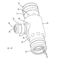
- the wire harness 10 in the present embodiment is a high-voltage wire harness attached to a hybrid vehicle or the like, and most of the wire harness 10 is routed under the floor of the vehicle body.
- the wire harness 10 is connected to the connector 11 at both ends, and is surrounded by the exterior material 12, and the interior of the exterior material 12 is completely sealed.
- the exterior material 12 includes a metal or resin pipe capable of collectively enclosing a plurality of electric wires 13, a corrugated tube without a slit, a waterproof cover that can be in close contact with the connector 11, and the like.
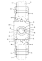
- the wire harness 10 has a cylindrical shape that can surround the wire harness 10, and includes a grommet 20 that is disposed at an intermediate portion in the length direction of the wire harness 10, and a magnetic core 40 that is housed in the housing portion 24 of the grommet 20. And.
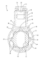
- the magnetic core 40 has an annular shape having a hollow portion 41 through which a plurality of electric wires 13 are collectively inserted.
- the magnetic core 40 has an oval cross-sectional shape, and the outer peripheral surface has a first outer surface 42 positioned at both ends in the longitudinal direction of the cross section and a second outer surface 43 positioned at both ends in the short-side direction. have.
- the pair of first outer surfaces 42 are arcuate surfaces, and the pair of second outer surfaces 43 are substantially parallel to each other.
- the hollow portion 41 has an oval shape, and the thickness of the magnetic core 40 is generally constant over the entire circumference.
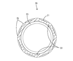
- the grommet 20 is made of an elastic material such as rubber, and has a main body 21 in which both end portions in the axial direction are connected to the exterior material 12.
- the main body 21 has a circular cross section (cylindrical shape).
- the grommet 20 has a symmetrical shape with respect to the center in the axial direction (length direction), and the mounting direction can be freely changed.
- connection portions 22 Both end portions in the axial direction of the main body portion 21 (hereinafter referred to as connection portions 22) can be fitted to the outside of the end portions of the exterior material 12 (see FIG. 7).
- a plurality (three) of lip portions 23 project from the inner peripheral surface of the connection portion 22 so as to be in close contact with the outer peripheral surface of the exterior material 12.
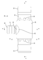
- the main body portion 21 is provided with a storage portion 24 that can store the magnetic core 40.
- the storage portion 24 is located at the center of the main body portion 21 in the axial direction.
- the storage part 24 has a cylindrical shape that is slightly larger in the vertical and horizontal directions than the connection part 22, and the internal space of the storage part 24 is larger in width than the internal space of the connection part 22.
- the inner peripheral surface of the storage unit 24 has an arc shape along the first outer surface 42 of the magnetic core 40, and the magnetic core 40 can rotate 360 degrees in the storage unit 24.
- the axial length of the storage portion 24 is larger than the axial length of the magnetic core 40, and the magnetic core 40 is axial in the storage portion 24. It is possible to move to.
- the accommodating part 24 has the contact surface 25 which can be contact
- the contact surfaces 25 are surfaces that are substantially orthogonal to the axial direction of the main body portion 21, and are formed at both ends of the storage portion 24 in the axial direction. As shown in FIG. 5, the contact surface 25 has an annular shape that extends continuously over the entire circumference of the storage portion 24, and projects inward from the inner peripheral surface of the connection portion 22. The magnetic core 40 is prevented from coming out of the storage portion 24 toward the connection portion 22 by contacting the contact surface 25.
- the main body 21 is formed with a through-hole 28 into which a waterproof material 29 having air permeability can be fitted (see FIG. 5).
- the through hole 28 is formed in a cylindrical protrusion 27 that protrudes outward from the storage portion 24.
- the cylindrical protrusion 27 has a cylindrical shape and is provided so as to protrude in the center in the axial direction and the width direction of the storage portion 24.
- the cylindrical projection 27 stands vertically from the storage portion 24, and the axis of the cylindrical projection 27 and the axis of the storage portion 24 are orthogonal to each other.
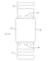
- the waterproof material 29 includes a breathable membrane 31 made of a moisture permeable waterproof material that exhibits a waterproof and dustproof function while having air permeability, and an attachment part 32 that holds the breathable membrane 31 and can be closely fitted to the cylindrical protrusion 27. It has.
- the attachment part 32 has a cylindrical shape that can be fitted into the cylindrical protrusion 27, and the gas permeable membrane 31 is fixed to the end surface of the attachment part 32.
- the ventilation structure 26 including the cylindrical protrusion 27 and the waterproof material 29 can adjust the internal pressure of the exterior material 12.
- the grommet 20 is provided with a first ventilation path 33 and a second ventilation path 34 for ensuring sufficient ventilation between the end side (connecting portion 22 side) of the main body 21 and the cylindrical protrusion 27. Yes.
- the first air passage 33 is an air passage communicating with the storage portion 24 and the connection portion 22 side, and a plurality (eight in this embodiment) are formed on the contact surface 25 as shown in FIG. .
- the first air passages 33 are arranged at equal intervals in the circumferential direction on the contact surface 25.
- One of the plurality of first air passages 33 on the contact surface 25 is disposed at the same position as the cylindrical protrusion 27 in the circumferential direction of the contact surface 25.
- Each first air passage 33 has a semicircular shape opened to the inner peripheral edge side of the contact surface 25.
- the area of the first air passage 33 is the largest on the abutment surface 25 and gradually decreases toward the end of the main body 21.
- the first air passage 33 is formed in the same position, the same number, and the same shape on both contact surfaces 25 of the storage portion 24.
- the first air passage 33 is an internal space of the protruding portion 35 formed at the end of the storage portion 24.
- Each protrusion 35 has a width dimension and a height dimension (projection dimension from the main body part 21) that gradually become smaller from the storage part 24 side toward the connection part 22 side. All the protrusions 35 have the same shape.
- the second air passage 34 is an air passage communicating with the storage portion 24 and the cylindrical protrusion 27, and is formed at the root of the cylindrical protrusion 27 on the peripheral surface of the storage portion 24. ing.
- the second air passage 34 is formed to extend radially outward from the storage portion 24 and to extend radially outward from the cylindrical projection 27.
- the second air passage 34 is an internal space of the bulging portion 36 provided at the root portion of the cylindrical protrusion 27 in the storage portion 24.
- the bulging portion 36 has a form partially bulging outward from the storage portion 24, and includes a first wall portion 37 that is substantially orthogonal to the axis of the cylindrical protrusion 27, and a peripheral edge of the first wall portion 37. And a second wall portion 38 that is inclined and connected to the storage portion 24.
- the first wall portion 37 has an annular shape protruding outward from the entire circumference of the cylindrical protrusion 27, and the second wall portion 38 is substantially the same from the entire circumference of the first wall portion 37. It goes down to the storage section 24 with a gradient.
- the magnetic core 40 is disposed between the magnetic core 40 and the grommet 20 in any position and in any orientation in the storage unit 24.
- a sufficient air passage (a space having an area larger than the area of the gas permeable membrane 31) is ensured. That is, as shown in FIG. 7, even if the magnetic core 40 is disposed at the end in the axial direction of the storage portion 24 and the end face in the axial direction of the magnetic core 40 abuts against the contact surface 25, the first air passage 33 ensures a sufficient air passage between the grommet 20 and the magnetic core 40. Further, as shown in FIG.
- the magnetic core 40 is disposed immediately below the ventilation structure portion 26 (center position in the axial direction of the storage portion 24), and the first outer surface 42 closes the base of the cylindrical protrusion 27. Even in such a case, the second air passage 34 ensures a sufficient air passage between the grommet 20 and the magnetic core 40.
- the magnetic core 40 is stored in the grommet 20.
- the magnetic core 40 is inserted into the grommet 20 from the end.
- the connecting portion 22 of the grommet 20 is elastically expanded, and the magnetic core 40 is stored in the storage portion 24.
- the magnetic core 40 accommodated in the accommodating portion 24 has a hollow portion 41 that opens in the same direction as the axis of the grommet 20, and a pair of first outer surfaces 42 are arranged in a posture along the inner peripheral surface of the accommodating portion 24. .
- the exterior material 12 is connected.
- the end portion of the exterior material 12 is fitted inside the connection portion 22 of the grommet 20, and a fixing member (not shown) such as a binding band is wound around the outer periphery and fixed.
- the connection portion 22 of the grommet 20 is in close contact with the end portion of the exterior material 12.
- the electric wire 13 is passed through the exterior material 12.
- a terminal fitting (not shown) is connected to one end of both ends of the electric wire 13 and is passed through the exterior material 12 from the end on the side where the terminal fitting is not connected.
- the bundled electric wires 13 are inserted into the outer packaging material 12 and the grommet 20 (the hollow portion 41 of the magnetic core 40), and the end portions of the electric wires 13 are pulled out from the outer packaging material 12.
- the connector 11 is connected to the end of the electric wire 13.
- Terminal fittings are connected to the end portions of the electric wires 13 drawn out from the exterior material 12, and the terminal fittings connected to both end portions of the electric wires 13 are sequentially inserted into the connector 11.
- the grommet 20 of the present embodiment is a grommet that is formed in a cylindrical shape that can surround the wire harness 10 and is arranged at an intermediate portion in the length direction of the wire harness 10, and both end portions in the axial direction surround the wire harness 10.
- the main body 21 has a main body 21 connected to another exterior material 12, and the main body 21 is provided with a storage portion 24 that can store the magnetic core 40. According to this configuration, an increase in the diameter of the wire harness 10 can be suppressed as compared with the case where the magnetic core 40 is mounted on the outside of the exterior material 12. Further, since the grommet 20 has a short length, the magnetic core 40 can be easily accommodated from the end. That is, according to the grommet 20 of the present embodiment, the magnetic core 40 can be easily attached to the wire harness 10 while suppressing an increase in the diameter of the wire harness 10.
- a through hole 28 into which a breathable waterproof material 29 can be fitted is formed in the main body 21.
- the ventilation structure part 26 can be provided in the grommet 20 which accommodates the magnetic body core 40 which can become a heat source, the internal pressure of the exterior material 12 can be adjusted effectively.
- a through hole 28 is formed in the storage portion 24. According to this configuration, the length dimension of the main body portion 21 can be suppressed smaller than when the ventilation structure portion 26 and the storage portion 24 are provided shifted in the length direction, and the ventilation structure portion 26 is magnetic. Since it arrange
- the storage portion 24 has a contact surface 25 that can contact both end surfaces of the magnetic core 40 in the axial direction, and the first contact portion 25 communicates with the end side of the main body portion 21 in the axial direction.
- a ventilation path 33 is provided. According to this configuration, even if the magnetic core 40 abuts against the abutment surface 25, the ventilation to the ventilation structure portion 26 is not hindered, so that the function of adjusting the internal pressure of the exterior material 12 is prevented from being lowered. be able to.
- a through hole 28 is formed in a cylindrical protrusion 27 that protrudes outward from the storage portion 24, and a first portion that communicates with the cylindrical protrusion 27 at the root of the cylindrical protrusion 27 in the peripheral surface of the storage portion 24.
- Two air passages 34 are provided. According to this configuration, even if the magnetic core 40 abuts on the base of the cylindrical protrusion 27 on the peripheral surface of the storage portion 24, the ventilation to the ventilation structure portion 26 is not hindered. It can prevent that the function which adjusts a pressure falls.
- the grommet 20 includes the ventilation structure 26, but the ventilation structure may not necessarily be provided in the grommet.
- the specific structure of the ventilation structure 26 has been described. However, the structure is not limited to this, and the structure of the ventilation structure can be arbitrarily changed.
- the ventilation structure portion 26 is provided in the storage portion 24. However, the present invention is not limited thereto, and the ventilation structure portion may be provided at a position shifted in the axial direction from the storage portion.
- the through hole 28 is formed in the cylindrical protrusion 27.
- the present invention is not limited to this, and the through hole may be formed without providing a protrusion in the main body, for example.
- the storage unit 24 has the contact surfaces 25 that can contact both end surfaces of the magnetic core 40 in the axial direction. The surface may not be provided, and for example, the magnetic core may be held by the elastic force in the diameter reducing direction of the storage portion.
- the shape of the 1st ventilation path 33, the number, the position, etc. were illustrated, it is not restricted to this, The shape of the 1st ventilation path, etc. can be changed arbitrarily.
- the shape and the like of the second air passage 34 are illustrated, but not limited thereto, the shape and the like of the second air passage can be arbitrarily changed.
Landscapes
- Engineering & Computer Science (AREA)
- Architecture (AREA)
- Civil Engineering (AREA)
- Structural Engineering (AREA)
- Mechanical Engineering (AREA)
- Installation Of Indoor Wiring (AREA)
- Insulated Conductors (AREA)
- Insulating Bodies (AREA)
- Non-Portable Lighting Devices Or Systems Thereof (AREA)
Priority Applications (2)
| Application Number | Priority Date | Filing Date | Title |
|---|---|---|---|
| US16/307,301 US20190135204A1 (en) | 2016-06-16 | 2017-05-26 | Grommet and wire harness |
| CN201780036558.7A CN109314380B (zh) | 2016-06-16 | 2017-05-26 | 护线套及线束 |
Applications Claiming Priority (2)
| Application Number | Priority Date | Filing Date | Title |
|---|---|---|---|
| JP2016-119594 | 2016-06-16 | ||
| JP2016119594A JP6651992B2 (ja) | 2016-06-16 | 2016-06-16 | グロメット及びワイヤハーネス |
Publications (1)
| Publication Number | Publication Date |
|---|---|
| WO2017217214A1 true WO2017217214A1 (ja) | 2017-12-21 |
Family
ID=60663595
Family Applications (1)
| Application Number | Title | Priority Date | Filing Date |
|---|---|---|---|
| PCT/JP2017/019673 Ceased WO2017217214A1 (ja) | 2016-06-16 | 2017-05-26 | グロメット及びワイヤハーネス |
Country Status (4)
| Country | Link |
|---|---|
| US (1) | US20190135204A1 (enExample) |
| JP (1) | JP6651992B2 (enExample) |
| CN (3) | CN109314380B (enExample) |
| WO (1) | WO2017217214A1 (enExample) |
Cited By (1)
| Publication number | Priority date | Publication date | Assignee | Title |
|---|---|---|---|---|
| CN110040080A (zh) * | 2018-01-15 | 2019-07-23 | 矢崎总业株式会社 | 电线的外部构件 |
Families Citing this family (6)
| Publication number | Priority date | Publication date | Assignee | Title |
|---|---|---|---|---|
| JP6724872B2 (ja) * | 2017-06-29 | 2020-07-15 | 住友電装株式会社 | ワイヤーハーネス |
| CN113574756B (zh) * | 2019-03-19 | 2023-02-21 | 住友电装株式会社 | 收纳构件和保护管的连接结构 |
| JP7284012B2 (ja) * | 2019-07-05 | 2023-05-30 | 矢崎総業株式会社 | 防水性通気膜のインサート成形構造、及び成形品 |
| US11358544B2 (en) | 2020-03-18 | 2022-06-14 | Yazaki Corporation | Wire harness including internal pressure adjuster |
| JP7449783B2 (ja) * | 2020-06-15 | 2024-03-14 | 古河電気工業株式会社 | グロメット、及び保持部材 |
| JP7301908B2 (ja) * | 2021-06-14 | 2023-07-03 | 矢崎総業株式会社 | コネクタ及びコネクタ付き電線 |
Citations (2)
| Publication number | Priority date | Publication date | Assignee | Title |
|---|---|---|---|---|
| JP2015027205A (ja) * | 2013-07-26 | 2015-02-05 | 株式会社オートネットワーク技術研究所 | ノイズ吸収具 |
| JP2016092264A (ja) * | 2014-11-06 | 2016-05-23 | 北川工業株式会社 | 磁性体コア収容ケース |
Family Cites Families (20)
| Publication number | Priority date | Publication date | Assignee | Title |
|---|---|---|---|---|
| US3585542A (en) * | 1969-10-08 | 1971-06-15 | William B Kindred | Electromagnetic switch assembly |
| US4435612A (en) * | 1982-03-09 | 1984-03-06 | Communication Technology Corporation | Cable splice housing |
| JPS6396721U (enExample) * | 1986-12-15 | 1988-06-22 | ||
| JPH0760956B2 (ja) * | 1987-02-19 | 1995-06-28 | 北川工業株式会社 | 雑音吸収具 |
| US5654526A (en) * | 1994-11-09 | 1997-08-05 | Sharp; Larry C. | Coupling apparatus and method for electrical conduit |
| JP3126922B2 (ja) * | 1996-07-19 | 2001-01-22 | 竹内工業株式会社 | ノイズ吸収装置 |
| JP3246599B2 (ja) * | 1997-03-14 | 2002-01-15 | ティーディーケイ株式会社 | ノイズ吸収装置 |
| US6515230B1 (en) * | 1999-03-24 | 2003-02-04 | Tdk Corporation | Noise absorber and case for noise absorber |
| US7352929B2 (en) * | 2006-06-30 | 2008-04-01 | Rockwell Collins, Inc. | Rotary joint for data and power transfer |
| JP5586142B2 (ja) * | 2008-11-10 | 2014-09-10 | 矢崎総業株式会社 | 線材の止水方法 |
| US8905795B2 (en) * | 2011-10-12 | 2014-12-09 | Apple Inc. | Spring-loaded contacts |
| CN103095084B (zh) * | 2011-10-27 | 2015-09-30 | 北京精密机电控制设备研究所 | 一种浸油式高比功率永磁无刷直流电机 |
| JP5737222B2 (ja) * | 2012-05-22 | 2015-06-17 | 住友電装株式会社 | 防水カバー |
| JP6095454B2 (ja) * | 2013-04-10 | 2017-03-15 | モレックス エルエルシー | コネクタ |
| JP6008249B2 (ja) * | 2013-07-04 | 2016-10-19 | 住友電装株式会社 | グロメット |
| JP6135584B2 (ja) * | 2014-04-02 | 2017-05-31 | 日立金属株式会社 | 配線部材 |
| JP6155246B2 (ja) * | 2014-10-24 | 2017-06-28 | 古河電気工業株式会社 | グロメット |
| JP6256308B2 (ja) * | 2014-11-06 | 2018-01-10 | 住友電装株式会社 | ワイヤハーネスのシールド構造 |
| JP6357142B2 (ja) * | 2015-12-18 | 2018-07-11 | 矢崎総業株式会社 | コアユニットおよびワイヤハーネス |
| JP6419126B2 (ja) * | 2016-10-14 | 2018-11-07 | 矢崎総業株式会社 | 電線接続構造、ノイズ低減ユニットおよびワイヤハーネス |
-
2016
- 2016-06-16 JP JP2016119594A patent/JP6651992B2/ja active Active
-
2017
- 2017-05-26 CN CN201780036558.7A patent/CN109314380B/zh active Active
- 2017-05-26 US US16/307,301 patent/US20190135204A1/en not_active Abandoned
- 2017-05-26 CN CN202010489546.3A patent/CN111724933B/zh active Active
- 2017-05-26 CN CN202010497405.6A patent/CN111724934B/zh active Active
- 2017-05-26 WO PCT/JP2017/019673 patent/WO2017217214A1/ja not_active Ceased
Patent Citations (2)
| Publication number | Priority date | Publication date | Assignee | Title |
|---|---|---|---|---|
| JP2015027205A (ja) * | 2013-07-26 | 2015-02-05 | 株式会社オートネットワーク技術研究所 | ノイズ吸収具 |
| JP2016092264A (ja) * | 2014-11-06 | 2016-05-23 | 北川工業株式会社 | 磁性体コア収容ケース |
Cited By (1)
| Publication number | Priority date | Publication date | Assignee | Title |
|---|---|---|---|---|
| CN110040080A (zh) * | 2018-01-15 | 2019-07-23 | 矢崎总业株式会社 | 电线的外部构件 |
Also Published As
| Publication number | Publication date |
|---|---|
| CN111724933B (zh) | 2021-11-12 |
| CN109314380A (zh) | 2019-02-05 |
| JP6651992B2 (ja) | 2020-02-19 |
| CN111724934B (zh) | 2021-11-12 |
| CN109314380B (zh) | 2020-06-26 |
| CN111724933A (zh) | 2020-09-29 |
| CN111724934A (zh) | 2020-09-29 |
| JP2017225256A (ja) | 2017-12-21 |
| US20190135204A1 (en) | 2019-05-09 |
Similar Documents
| Publication | Publication Date | Title |
|---|---|---|
| JP6651992B2 (ja) | グロメット及びワイヤハーネス | |
| JP5737222B2 (ja) | 防水カバー | |
| JP7117337B2 (ja) | グロメット、及び、ワイヤハーネス | |
| CN107826055B (zh) | 护线套的车身安装结构 | |
| JP7110258B2 (ja) | グロメット、及び、ワイヤハーネス | |
| JP5892427B2 (ja) | ホルダ及びこれを用いた編組線の端末接続構造 | |
| US11242016B2 (en) | Grommet and wire harness | |
| WO2018088181A1 (ja) | 外装通気部材 | |
| JP2016086520A (ja) | グロメット | |
| US10651640B2 (en) | Grommet and wire harness using the same | |
| JP6897822B2 (ja) | グロメット及びワイヤハーネス | |
| JP2009005422A (ja) | コルゲートチューブ | |
| JP7077979B2 (ja) | 電力変換装置 | |
| JP2010220362A (ja) | チューブ形態維持部材、コルゲートチューブの支持構造及びコルゲートチューブの支持構造の製造方法 | |
| JP6760100B2 (ja) | 通気部材及びハーネス | |
| JP6897823B2 (ja) | ワイヤハーネス | |
| JP6860096B2 (ja) | グロメット及びワイヤハーネス | |
| JP2012100460A (ja) | ワイヤーハーネス | |
| JP5166841B2 (ja) | 保護部材 | |
| JP6904820B2 (ja) | 分岐プロテクタ及びワイヤーハーネス | |
| US9825444B2 (en) | Electrical wire cover | |
| JP2024046861A (ja) | ホルダ、及び、ワイヤハーネス | |
| JP2022078603A (ja) | 電線保護具、及び、電線保護具の車体パネルへの取付方法 | |
| JP2021048744A (ja) | グロメット固定構造 | |
| JP2017143594A (ja) | プロテクタ、及び、ワイヤハーネス |
Legal Events
| Date | Code | Title | Description |
|---|---|---|---|
| 121 | Ep: the epo has been informed by wipo that ep was designated in this application |
Ref document number: 17813116 Country of ref document: EP Kind code of ref document: A1 |
|
| NENP | Non-entry into the national phase |
Ref country code: DE |
|
| 122 | Ep: pct application non-entry in european phase |
Ref document number: 17813116 Country of ref document: EP Kind code of ref document: A1 |