WO2017213231A1 - 眼内レンズ押出補助具 - Google Patents
眼内レンズ押出補助具 Download PDFInfo
- Publication number
- WO2017213231A1 WO2017213231A1 PCT/JP2017/021355 JP2017021355W WO2017213231A1 WO 2017213231 A1 WO2017213231 A1 WO 2017213231A1 JP 2017021355 W JP2017021355 W JP 2017021355W WO 2017213231 A1 WO2017213231 A1 WO 2017213231A1
- Authority
- WO
- WIPO (PCT)
- Prior art keywords
- intraocular lens
- fluid
- syringe
- main body
- plunger
- Prior art date
- Legal status (The legal status is an assumption and is not a legal conclusion. Google has not performed a legal analysis and makes no representation as to the accuracy of the status listed.)
- Ceased
Links
Images





Classifications
-
- A—HUMAN NECESSITIES
- A61—MEDICAL OR VETERINARY SCIENCE; HYGIENE
- A61F—FILTERS IMPLANTABLE INTO BLOOD VESSELS; PROSTHESES; DEVICES PROVIDING PATENCY TO, OR PREVENTING COLLAPSING OF, TUBULAR STRUCTURES OF THE BODY, e.g. STENTS; ORTHOPAEDIC, NURSING OR CONTRACEPTIVE DEVICES; FOMENTATION; TREATMENT OR PROTECTION OF EYES OR EARS; BANDAGES, DRESSINGS OR ABSORBENT PADS; FIRST-AID KITS
- A61F2/00—Filters implantable into blood vessels; Prostheses, i.e. artificial substitutes or replacements for parts of the body; Appliances for connecting them with the body; Devices providing patency to, or preventing collapsing of, tubular structures of the body, e.g. stents
- A61F2/02—Prostheses implantable into the body
- A61F2/14—Eye parts, e.g. lenses or corneal implants; Artificial eyes
- A61F2/16—Intraocular lenses
Definitions
- the present invention relates to an intraocular lens pushing aid.
- Intraocular lenses that are inserted as a substitute for the crystalline lens in order to correct the refraction by replacing the human turbid crystalline lens in the treatment of cataract are in practical use.
- intraocular lens insertion surgery in the treatment of cataracts, for example, a few millimeters of incision wound (incision) is provided at the edge of the cornea, cornea, etc., and the lens is crushed by ultrasonic phacoemulsification, etc. After removal, the intraocular lens is inserted and secured by an intraocular lens insertion instrument.
- techniques for assisting insertion of an intraocular lens into the eye using an intraocular lens insertion device have been proposed (for example, Patent Documents 1, 2, and 3).
- JP 2004-261263 A Special table 2012-505066 gazette International Publication No. 2008/149927
- the intraocular lens housed in the intraocular lens housing portion of the instrument body is pressed by the plunger to move within the instrument body and enter the eye from the instrument body. Released.
- the plunger is moved to the intraocular lens at the moment when the intraocular lens is released from the distal end of the insertion instrument to the outside.
- the resistance received from the power drops momentarily.
- the surgeon needs to adjust the force pushing the plunger according to the movement state of the intraocular lens.
- the technology disclosed herein has been made in view of the above circumstances, and an object thereof is to provide an intraocular lens extrusion assisting tool that improves the operability of the intraocular lens insertion device.
- An intraocular lens push-out assisting tool of the present disclosure is provided with a substantially cylindrical instrument body having an insertion tube portion at the tip for inserting an intraocular lens into the eye, and a slideable inside the instrument body.
- An intraocular lens pushing aid that can be connected to an intraocular lens insertion device having an intraocular lens pushing member that pushes and moves into the insertion tube and pushes it into the eye, and a body part that is a tubular member;
- a collar provided at one end of the main body and having a connection mechanism for connecting to an intraocular lens insertion instrument; and a connection provided at the other end of the main body and connectable to a fluid supply means for supplying fluid into the main body.
- the moving member is provided in the main body and moves with the pressure of the supplied fluid, and has at least one hole provided on a side surface of the main body and through which the fluid passes.
- the operator can control the movement of the moving member pushed by the fluid, and thus the movement of the intraocular lens pushing member pushed by the moving member, by adjusting the amount of the fluid supplied to the main body part with a finger or the like.
- the intraocular lens pushing member can be moved more stably.
- an index indicating the position of the intraocular lens pushing member may be provided on the side surface of the main body when the buttock is connected to the intraocular lens insertion device.
- the hole may be configured to be closed in advance by a sealing member that can be opened by an external force.
- the sealing member may be a tape.
- an intraocular lens pushing aid that improves the operability of the intraocular lens insertion device.
- FIG. 2A and FIG. 2B are diagrams illustrating schematic configurations of an intraocular lens insertion device and a syringe according to an embodiment.
- FIG. 3A and FIG. 3B are diagrams showing a schematic configuration of an intraocular lens in one embodiment. It is a figure which shows schematic structure of the nozzle main body in one Embodiment.
- Fig.5 (a) and FIG.5 (b) are figures which show schematic structure of the positioning member in one Embodiment.
- FIG. 6A and FIG. 6B are diagrams showing a schematic configuration of a plunger in one embodiment.
- FIG. 7B are diagrams illustrating an intraocular lens insertion device and a syringe according to an embodiment. It is a figure which shows schematic structure of the injection cylinder which has a syringe in one Embodiment.
- FIG. 9A and FIG. 9B are diagrams showing a schematic configuration of an intraocular lens insertion device and a syringe in one modified example. It is a figure which shows schematic structure of the intraocular lens insertion instrument and syringe in one modification.
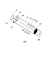
- FIG. 1 shows a syringe 20 used as an intraocular lens pushing aid according to the present embodiment.
- the syringe 20 has a cylindrical tubular member 20a.
- the cylindrical member 20a corresponds to an example of the main body.
- the cylindrical member 20a is provided with a packing 20c as a moving member so as to come into contact with the inner wall of the cylindrical member 20a. It is desirable that the packing 20c has a rigidity that does not bend when sliding.
- a fluid supply unit 20 d is provided as a fluid supply unit for supplying fluid to a space surrounded by the syringe 20 and the packing 20 c.
- the fluid supply unit 20d has a substantially conical shape and has an opening 20e that is a through hole through which a fluid passes.
- the shape of the syringe 20 is not limited to a cylinder, and can be formed in an arbitrary shape.
- a flange 20 h is provided on the other end side of the syringe 20.
- a pair of through holes 20i are provided in the flange 20h so as to face each other with the opening 20r interposed therebetween.
- the flange 20h corresponds to an example of a flange portion.
- the holding portion 11 of the nozzle body 10 of the intraocular lens insertion device 1 is inserted through the through hole 20i.
- the intraocular lens insertion device 1, the nozzle body 10, and the hold unit 11 will be described later.
- Three through holes 20j, 20k, and 20m that penetrate the syringe 20 are provided on the side surface of the syringe 20.
- the number of through holes is not limited to three.
- the through holes 20j, 20k, and 20m are closed with transparent tapes 20n, 20p, and 20q, respectively.
- the tapes 20n, 20p, and 20q correspond to an example of a sealing member that can be opened by an external force.
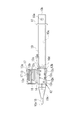
- FIG. 2 shows a schematic configuration of the intraocular lens insertion device 1 and the syringe 20 of the present embodiment.
- 2A is a plan view of the intraocular lens insertion device 1 and the syringe 20 when the stage lid portion 13 is opened
- FIG. 2B is an intraocular lens insertion device when the stage lid portion 13 is closed. 1 and a side view of the syringe 20 are shown.
- the intraocular lens insertion instrument 1 includes a nozzle body 10 as an instrument body, a plunger 30 as an intraocular lens push-out member, a stage unit 12 and a stage lid unit 13 as an intraocular lens storage unit.
- the syringe 20 is attached to the nozzle body 10 and functions as an intraocular lens pushing aid that assists in pushing out the intraocular lens.
- the nozzle main body 10 of the intraocular lens insertion device 1 is formed in a cylindrical shape having a substantially rectangular cross section, and one end of the nozzle body 10 is greatly open (hereinafter, the side having the large opening is referred to as the rear end 10b), and the other side.
- tip part 10a narrowed down are provided in the edge part. As shown in FIG. 2 (b), the tip 10a is opened obliquely.
- the plunger 30 is inserted into the nozzle body 10 and can reciprocate.
- the direction from the rear end portion 10b of the nozzle body 10 to the front end portion 10a is the front direction
- the opposite direction is the rear direction
- the front side of the page in FIG. 2 (a) is the upper direction
- the reverse direction is the lower direction
- the front side of the page is the left direction
- the opposite direction is the right direction.
- the upper side is the front side of the optical axis of the lens body 2a, which will be described later
- the lower side is the rear side of the optical axis of the lens body 2a
- the front side is the front side in the pressing direction by the plunger 30, and the rear side is pressed by the plunger 30 Corresponds to the rear side.
- a stage portion 12 for setting the intraocular lens 2 is provided on the rear side of the nozzle portion 15 in the nozzle body 10.
- the stage portion 12 is configured such that the upper side of the nozzle body 10 is opened by opening the stage lid portion 13.
- a positioning member 50 is attached to the stage portion 12 from the lower side of the nozzle body 10. By this positioning member 50, the intraocular lens 2 is stably held in the stage portion 12 even before use (during transportation).
- the intraocular lens 2 is placed on the stage unit 12 and the front side of the optical axis is on the upper side with the stage lid 13 opened and the positioning member 50 attached to the stage unit 12 at the time of manufacture. Set to be. Then, after the stage lid 13 is closed, it is shipped and sold. The surgeon inserts the hold part 11 of the nozzle body 10 into the through hole 20 i of the syringe 20 and engages the syringe 20 and the hold part 11. As shown in FIG. 2B, in this embodiment, since the holding portion 11 of the nozzle body 10 extends in the up-down direction, the flange 20h is formed in the up-down direction in the syringe 20 that is received by the nozzle body 10. A pair is provided.
- the operator removes the positioning member 50 with the stage lid portion 13 closed, and then moves the packing 20c using the fluid supplied to the syringe 20, and the plunger 30 moves the plunger 30 of the nozzle body 10 by the packing 20c. It is moved to the tip side.
- the intraocular lens 2 is pressed by the plunger 30, and the intraocular lens 2 is moved to the nozzle portion 15 and then released from the distal end portion 10 a into the eyeball.
- the nozzle main body 10, the plunger 30, and the positioning member 50 in the intraocular lens insertion device 1 are formed of a resin material such as polypropylene.
- Polypropylene is a material with a proven track record in medical equipment and high reliability such as chemical resistance.
- the intraocular lens insertion device 1 is a preset type in which the intraocular lens 2 is set in advance in the intraocular lens insertion device 1 before shipment. May be a so-called separate type that is set in the intraocular lens insertion device 1.
- a region surrounded by the cylindrical member 20a, the packing 20c, and the fluid supply unit 20d is a sealed space.
- the region on the fluid supply unit 20d side is defined as the first region 20f with the packing 20c as a boundary, and the plunger 30 side region inserted into the nozzle body 10 Is the second region 20g.
- notches 11 a are provided at both ends of the hold unit 11. For this reason, once the flange 20h of the syringe 20 is attached to the hold part 11, the engagement between the flange 20h and the hold part 11 is not released by the notch 11a. Note that the notch 11a may be provided in the flange 20h instead of the hold portion 11 or in addition to the hold portion 11 as long as the engagement between the flange 20h and the hold portion 11 is not released.
- the syringe 20 is attached to the nozzle body 10 it is necessary to provide at least one opening structure at a connection portion between the syringe 20 and the nozzle body 10 so that the second region 20 g does not become a sealed space. This is because the air existing in the second region 20g before the attachment of the syringe 20 and the nozzle body 10 needs to be discharged to the outside as the packing 20c moves.
- the fluid supply part 20d has a front side connected to the rear end of the cylindrical member 20a and a rear side connectable to the tip of the tube 40.
- the fluid supply unit 20d corresponds to an example of a fluid supply unit.
- the opening 20e is dimensioned to be engageable with an inner diameter or an outer diameter of a general medical tube.
- a highly versatile medical tube can be connected to the fluid supply unit 20d, and it is not necessary to prepare a special tube.
- a fluid supply source (not shown) for supplying fluid into the first region 20f is connected to the other end of the tube 40 connected to the fluid supply unit 20d. Examples of the fluid supply source include a compressor for supplying compressed air and a pump for supplying cold / hot water.
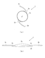
- FIG. 3 is a diagram showing a schematic configuration of the intraocular lens 2 according to the present embodiment.
- 3A is a plan view and FIG. 3B is a side view. Note that the orientation of the intraocular lens 2 does not correspond between FIGS. 3 (a) and 3 (b).
- the intraocular lens 2 is a so-called one-piece type in which the lens portion and the support portion are integrally formed of the same material, and the material of the lens is a soft acrylic material.
- the intraocular lens 2 includes a lens body 2a having a predetermined refractive power, and two long flat plate-like support portions 2b connected to the lens body 2a for holding the lens body 2a in the eyeball. .
- the lens body 2a and the support portion 2b are made of a flexible resin material.
- the lens body 2a and the support portion 2b are connected to each other via a joint portion 2d.
- the intraocular lens 2 in this embodiment demonstrates as a one-piece type, the three-piece type in which the lens main body and the support part are formed with the separate member may be sufficient.
- one of the two support portions 2b is on the rear side of the lens body 2a, and the other support portion 2b is on the front side of the lens body 2a.
- the intraocular lens 2 is set on the stage unit 12 so as to be disposed.
- positioned at the front side of the lens main body 2a be a front support part
- positioned at the rear side of the lens main body 2a be a back support part.
- the support portion 2b is subjected to a textured process.
- the posture of the intraocular lens 2 can be stabilized.
- an appropriate frictional force is generated between the support portion 2 b and the inner wall surface of the nozzle body 10, whereby the intraocular lens 2 is moved to the nozzle. It can be prevented from rotating in the main body 10.
- the support portion 2b since the support portion 2b is subjected to the embossing process, the support portion 2b can be prevented from sticking to the lens body 2a when the intraocular lens 2 is folded in the nozzle body 10.
- FIG. 4 shows a plan view of the nozzle body 10.
- the intraocular lens 2 is set on the stage unit 12. In this state, the intraocular lens 2 is pressed by the plunger 30 and is released from the distal end portion 10a.
- a through hole 10 c whose cross-sectional shape changes according to a change in the outer shape of the nozzle body 10 is provided in the nozzle body 10.
- the intraocular lens 2 is released, the intraocular lens 2 is deformed and folded according to a change in the cross-sectional shape of the through hole 10c in the nozzle body 10, and is formed on the patient's eyeball. It is released after being transformed into a shape that is easy to enter an incision.
- the tip portion 10a has a shape cut obliquely so that the upper region of the nozzle portion 15 is in front of the lower region.
- the shape of the tip portion 10a that is obliquely cut may be linearly obliquely cut when viewed from the left-right direction, or may have a bulge outward, that is, a curved shape. It may be cut into
- a stage groove 12 a having a width slightly larger than the diameter of the lens body 2 a of the intraocular lens 2 is formed in the stage portion 12.
- the dimension in the front-rear direction of the stage groove 12 a is set to be larger than the maximum width dimension including the support portions 2 b and 2 b extending on both sides of the intraocular lens 2.
- a set surface 12b is formed by the bottom surface of the stage groove 12a. The vertical position of the set surface 12b is set higher than the height position of the bottom surface of the through hole 10c of the nozzle body 10, and the set surface 12b and the bottom surface of the through hole 10c are connected by a bottom slope 10d. .
- the stage portion 12 and the stage lid portion 13 are integrally formed.
- the stage lid portion 13 has the same size in the front-rear direction as the stage portion 12.
- the stage lid portion 13 is connected by a thin plate-like connecting portion 14 formed by extending the side surface of the stage portion 12 to the stage lid portion 13 side.
- the connecting portion 14 is formed to be bendable at the center portion, and the stage lid portion 13 can be closed by overlapping the stage portion 12 from above by bending the connecting portion 14.
- stage lid portion 13 ribs 13 a and 13 b are provided on the surface facing the set surface 12 b when the lid is closed in order to reinforce the stage lid portion 13 and stabilize the position of the intraocular lens 2. Further, a guide protrusion 13 c is provided as a guide on the upper side of the plunger 30.
- the stage lid 13 is provided with an injection hole 16 for injecting a viscoelastic substance such as hyaluronic acid for smooth movement of the intraocular lens in the nozzle.
- the protrusion 17 has a function of making it easier to inject the viscoelastic material by guiding the needle of the syringe to be injected into the injection hole 16.
- FIG. 5 shows a schematic configuration of the positioning member 50.
- FIG. 5A shows a plan view of the positioning member 50
- FIG. 5B shows a left side view of the positioning member 50.
- the positioning member 50 is configured as a separate body from the nozzle main body 10, and has a structure in which a pair of side wall portions 51, 51 are connected by a connecting portion 52. At the lower ends of the respective side wall portions 51, holding portions 53, 53 extending outward and extending are formed.
- a pair of first mounting portions 54 and 54 projecting upward are formed inside the side wall portions 51 and 51. Further, first positioning portions 55 and 55 are formed to protrude from the outer peripheral side of the upper end surfaces of the first placement portions 54 and 54. The distance between the inner sides of the first positioning portions 55 and 55 is set slightly larger than the diameter of the lens body 2 a of the intraocular lens 2.
- a pair of second mounting portions 56 and 56 projecting upward are formed inside the side wall portions 51 and 51.
- the heights of the upper surfaces of the second mounting parts 56 and 56 are equal to the heights of the upper surfaces of the first mounting parts 54 and 54.
- second positioning portions 57 and 57 that protrude further upward are formed on the outer portions of the upper surfaces of the second placement portions 56 and 56 over the entire left and right direction of the second placement portions 56 and 56. .
- the distance between the inner sides of the second positioning portions 57 and 57 is set to be slightly larger than the diameter dimension of the lens body 2 a of the intraocular lens 2.
- a third placement portion 58 on which a part of the front support portion of the support portion 2b of the intraocular lens 2 is placed is formed inside the side wall portions 51 and 51. Further, a third positioning portion 59 that protrudes further upward from the third placement portion 58 is formed. A part of the front support part comes into contact with the third positioning part 59.
- the 4th mounting part 60 in which a part of back support part is mounted among the support parts 2b of the intraocular lens 2 is formed inside the side wall parts 51 and 51. As shown in FIG. Furthermore, the 4th positioning part 61 which protrudes further upwards from the 4th mounting part 60 is formed. A part of the rear support part comes into contact with the fourth positioning part 61.
- the heights of the upper surfaces of the fourth placement unit 60 and the fourth positioning unit 61 are higher than the heights of the upper surfaces of the first to third placement units and the first to third positioning units. Is also provided to be low.
- a rotation preventing wall portion 62 for preventing unnecessary rotation when the positioning member 50 is removed is provided.
- the set surface 12b of the nozzle body 10 is formed with a set surface through hole 12c that penetrates the set surface 12b in the thickness direction.
- the outer shape of the set surface through hole 12c is substantially similar to the shape of the first to fourth placement portions and the first to fourth positioning portions of the positioning member 50 as viewed from above.
- the bottom surface of the outer periphery of the lens body 2a is placed on the upper surfaces of the first placement portions 54 and 54 and the second placement portions 56 and 56.
- the position of the lens body 2a is restricted with respect to the horizontal direction (the direction horizontal to the set surface 12b) by the first positioning portions 55, 55 and the second positioning portions 57, 57.
- the two support portions 2b of the intraocular lens 2 are placed on the upper surfaces of the third placement portion 58 and the fourth placement portion 60, respectively.
- the positions of the two support portions 2b are restricted with respect to the horizontal direction by the third positioning portion 59 and the fourth positioning portion 61, respectively.
- the distal end portion 10a of the nozzle portion 15 of the nozzle body 10 is inserted into the incision provided in the eye tissue.
- the distal end portion 10a has an oblique opening shape, it can be easily inserted into the incision.
- the fluid is supplied to the syringe 20, and the pressing plate portion 33 of the plunger 30 moves toward the distal end side of the nozzle body 10 as the packing 20 c is moved by the fluid. Pushed in.
- the plunger 30 has a slightly larger longitudinal length than the nozzle body 10. And it forms from the action part 31 of the front end side based on a column shape, and the insertion part 32 of the rear end side based on a rectangular rod shape. And the action part 31 is comprised including the cylindrical part 31a made into the column shape, and the thin plate-shaped flat part 31b extended in the left-right direction of the cylindrical part 31a.
- a notch 31 c is formed at the tip of the action part 31.
- the notch 31c is formed in a groove shape that opens upward in the action portion 31 and penetrates in the left-right direction.
- the groove wall on the distal end side of the cutout portion 31 c is formed with an inclined surface that goes upward as it goes to the distal end side of the action portion 31.
- the insertion portion 32 has a substantially H-shaped cross section as a whole, and the horizontal and vertical dimensions thereof are set slightly smaller than the through hole 10 c of the nozzle body 10.
- a disc-shaped pressing plate portion 33 is formed at the rear end of the insertion portion 32 so as to spread in the vertical and horizontal directions.
- a claw portion 32 a that protrudes upward from the insertion portion 32 and that can move up and down by the elasticity of the material of the plunger 30 is formed at a portion of the insertion portion 32 that is ahead of the center in the front-rear direction.
- claw portion 32a and the locking hole 10e are formed at the positions where the distal end of the action portion 31 is located on the rear side of the lens body 2a of the intraocular lens 2 set on the stage portion 12 in the engaged state.
- the support portion 2b on the rear side of the main body 2a is set so that the cutout portion 31c can be supported from below.
- the plunger 30 Prior to the accommodation of the intraocular lens 2 of the intraocular lens insertion device 1 configured as described above, the plunger 30 is inserted into the nozzle body 10 and disposed at the initial position. Further, as described above, the positioning member 50 is attached to the nozzle body 10 from below the set surface 12b. Thereby, the 1st mounting part 54 and the 2nd mounting part 56 of the positioning member 50 are hold
- the lens body 2 a of the intraocular lens 2 is placed and positioned on the upper surfaces of the first placement part 54 and the second placement part 56 with the support part 2 b facing the front-rear direction of the nozzle body 10.
- a part of the support portion 2b on the rear side of the intraocular lens 2 is sandwiched between the notches 31c of the plunger 30 and is supported by the bottom surface thereof.
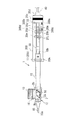
- FIG. 7 illustrates the relative positional relationship between the plunger 30, the packing 20 c of the syringe 20, and the through holes 20 j, 20 k, and 20 m when the intraocular lens 2 moves to the tip portion 10 a of the nozzle body 10.
- the operator peels off the tape 20q (see FIG. 8) covering the through hole 20m.
- the operator operates the fluid supply source connected to the tube 40 to supply a constant flow rate of fluid to the tube. 40 and the fluid supply part 20d to supply to the first region 20f.
- the packing 20c moves toward the nozzle body 10 and presses the plunger 30 toward the nozzle body 10 to move it. Thereby, the intraocular lens 2 can be moved to the tip portion 10 a side of the nozzle body 10.
- the function of the through hole 20m will be described. As shown in FIG. 7B, when the packing 20c moves beyond the through hole 20m, the fluid supplied to the first region 20f flows out from the through hole 20m.
- the operator operates the fluid supply source after closing the through hole 20m with the hand of the operator.
- the operator blocks the through hole 20m with a finger or the like, so that the fluid penetrates. It does not flow out of the cylindrical member 20a from the hole 20m.
- the packing 20c is pushed by the fluid and moves further from the position illustrated in FIG. 7B to the tip portion 10a side of the nozzle body.
- the plunger 30 is pressed and moved by the packing 20c, and further moves the intraocular lens 2 to the tip portion 10a side of the nozzle body 10.
- the operator When the packing 20c moves further from the position illustrated in FIG. 7B to the tip 10a side of the nozzle body, the operator temporarily removes the finger from the through hole 20m, thereby temporarily supplying the fluid to the through hole 20m. And the movement of the packing 20c can be stopped. Therefore, the operator can control the movement of the packing 20c pushed by the fluid by closing the through hole 20m with a finger or the like, or separating the finger or the like that has closed the through hole 20m from the through hole 20m. . Thereby, the operator does not need to push the plunger 30 directly with a finger, and can concentrate on other operations and treatments such as adjustment of the position of the nozzle body 10 with respect to the incision.
- the through hole 20m may not be blocked by the surgeon's hand.
- the fluid even if the fluid is supplied to the first region 20f after the packing 20c has moved to the position illustrated in FIG. 7B, the fluid flows out of the cylindrical member 20a from the through hole 20m.
- the packing 20c stops at the position shown in FIG. 7B without being pushed by the fluid.
- the phenomenon that the packing 20c continues to push the plunger 30 toward the tip portion 10a of the nozzle body 10 is avoided.
- Can do As a result, it is possible to prevent the intraocular lens 2 from being released from the distal end portion 10a of the nozzle body 10 against the operator's intention.
- the positions of the through holes 20j, 20k, and 20m in the syringe 20 are determined based on the length of the plunger 30 of the intraocular lens insertion device 1 that is assumed to be connected to the syringe 20. Specifically, before the intraocular lens 2 is released from the tip portion 10a of the nozzle body 10 by the plunger 30, the movement of the packing 20c may be stopped using any of the through holes 20j, 20k, and 20m. The positions of the through holes 20j, 20k, and 20m are determined so that they can be performed.
- intraocular lens insertion instruments A, B, and C can be connected to the syringe 20.
- the length of the plunger extending from the rear end portion (10b in FIGS. 2 and 7) of the nozzle body of the intraocular lens insertion devices A, B, and C is assumed that the intraocular lens insertion devices A, B, and C are long in this order.
- the movement of the packing 20c is stopped using the through hole 20m
- the intraocular lens insertion instrument B is connected to the syringe 20
- the movement of the packing 20c is considered to be stopped using the through hole 20j.
- the plungers of the insertion devices A, B, and C are moved, the through-hole 20j in the syringe 20 can be stopped so that the movement of the packing 20c can be stopped before the intraocular lens 2 is released from the distal end portion 10a of the nozzle body 10.
- 20k, and 20m may be determined.
- the diameter of the through holes 20j, 20k, and 20m is a circle having a diameter of 1 mm or more and 3 mm or less, the fluid supplied to the syringe 20 is sufficient to escape from the through holes 20j, 20k, and 20m.
- the through holes 20j, 20k, and 20m can be sufficiently blocked by pressing with an operator's finger or the like.
- the shape of the hole is not limited to a circle.
- FIG. 8 shows an example in which the syringe 20 is used as a part of the syringe barrel 1000.
- the syringe 20 is connected to the packing 20 c of the syringe 20 by the tip of the plunger 70 as the push-out member of the syringe barrel 1000, so that the syringe 20 can assist in pushing the intraocular lens of the intraocular lens insertion device 1.
- it Before being used as a tool, it functions as a syringe of a general syringe cylinder 1000.
- FIG. 9 shows a schematic configuration of a syringe 200 according to a modification.
- protrusions 200n, 200p, and 200q that close the through holes 20j, 20k, and 20m are provided instead of the tapes 20n, 20p, and 20q of the syringe 20 described above.
- the protrusions 200n, 200p, and 200q correspond to an example of a sealing member that can be opened by an external force.
- the protrusions 200n, 200p, and 200q are configured so as to be crushed and open when a predetermined external force is applied by an operator's finger or the like of the intraocular lens insertion device 1.
- the operator uses the through holes 20j, 20k, and 20m by opening the holes by crushing the protrusions 200n, 200p, and 200q in the same manner as described above.
- the movement of the plunger can be adjusted.
- the plug 200w that can be opened and closed for allowing the fluid supplied to the first region 20f of the syringe 200 to escape from the syringe 200 to the fluid supply unit 20d side or the fluid supply unit 20d from the packing 20c.
- the stopper 200w is opened and closed by the operator. Further, before the fluid is supplied to the syringe 200, the stopper 200w is opened. Therefore, for example, even if the fluid supply amount suddenly increases abnormally immediately after the fluid supply to the syringe 200 is started, the fluid flows out from the stopper 200w, so that the fluid flows into the packing 20c and eventually the packing 20c. The moving speed of the pushed plunger 30 can be relaxed.
- the stopper 200w can be used as a safety device for preventing the moving speed of the packing 20c from becoming abnormal when supplying fluid.
- FIG. 10 shows a schematic configuration of a syringe 300 according to a modification.
- an index indicating the position of the pressing plate portion 33 of the plunger 30 when the syringe 300 is attached to the intraocular lens insertion device 1 is provided on the side surface of the syringe 300.
- an index “A” 300 a indicating the position of the pressing plate portion 33 and an index line 300 b are provided on the side surface of the syringe 300.
- the length of the plunger of the intraocular lens insertion device varies depending on the manufacturer.
- a manufacturer or a symbol indicating a model number of the intraocular lens insertion device 1 may be used.
- an index “B” 300c and an index line 300d similar to the index “A” 300a and the index line 300b are provided on the side surface of the syringe 300.
- the index “B” 300d is an index that indicates the position of the pressing plate portion of the plunger when the syringe 300 is attached to another intraocular lens insertion device having a different plunger length from the intraocular lens insertion device 1. .
- the position of the pressing plate portion of the plunger can be grasped based on the index and the index line. As a result, the operator can easily determine which of the through holes 20j, 20k, and 20m is used to easily adjust the packing 20c and the movement of the plunger.
- Intraocular lens insertion instrument 2 Intraocular lens 10 Nozzle main body 20,200,300 Syringe 20a Cylindrical member 20j, 20k, 20m Through-hole 20n, 20p, 20q Tape 200n, 200p, 200q Protrusion 200w Plug 30 Plunger 33 Pressing plate Part 300a, 300c indicator 300b, 300d indicator line
Landscapes
- Health & Medical Sciences (AREA)
- Ophthalmology & Optometry (AREA)
- Cardiology (AREA)
- Oral & Maxillofacial Surgery (AREA)
- Transplantation (AREA)
- Engineering & Computer Science (AREA)
- Biomedical Technology (AREA)
- Heart & Thoracic Surgery (AREA)
- Vascular Medicine (AREA)
- Life Sciences & Earth Sciences (AREA)
- Animal Behavior & Ethology (AREA)
- General Health & Medical Sciences (AREA)
- Public Health (AREA)
- Veterinary Medicine (AREA)
- Prostheses (AREA)
Abstract
眼内レンズ挿入器具の操作性を向上させる眼内レンズ押出補助具を提供する。 眼内レンズを眼内に挿入する挿入筒部を先端に有する略筒状の器具本体と、器具本体内を摺動可能に設けられ、眼内レンズを押圧して挿入筒部に移動させて眼内に押し出す眼内レンズ押出部材とを有する眼内レンズ挿入器具に接続可能な眼内レンズ押出補助具(20)であって、筒状部材である本体部(20a)と、本体部(20a)の一端に設けられ、眼内レンズ挿入器具と接続する接続機構を有する鍔部(20h)と、本体部(20a)の他端に設けられ、本体部(20a)内に流体を供給する流体供給手段と接続可能な接続部(20d)と、本体部(20a)内に設けられ、供給される流体の圧力で移動する移動部材(20c)と、本体部(20a)の側面に設けられ、流体が通る少なくとも1つの孔(20j,20k,20m)とを有する。
Description
本発明は、眼内レンズ押出補助具に関する。
白内障治療においてヒト混濁水晶体を置換して屈折を補正するために水晶体の代用として挿入される眼内レンズが実用に供されている。白内障治療における眼内レンズ挿入手術においては、例えば角膜、強角膜などの縁に数ミリの切開の創口(切開創)が設けられ、超音波水晶体乳化吸引術などにより水晶体が粉砕されて切開創から取り除かれた後、眼内レンズ挿入器具により眼内レンズが挿入および固定される。そして、近年においては、眼内レンズ挿入器具による眼内レンズの眼内への挿入を補助する技術が提案されている(例えば、特許文献1、2、3)。
眼内レンズを眼内に挿入する際は、器具本体の眼内レンズ収納部に収納された眼内レンズが、プランジャーにより押圧されることで器具本体内を移動して器具本体から眼内に放出される。そして、プランジャーの移動により眼内レンズが器具本体から眼内に放出される一連の動作において、眼内レンズが挿入器具の先端から外部に放出されるその瞬間においては、プランジャーが眼内レンズから受ける抵抗力は瞬間的に低下する。このように、術者は、眼内レンズの移動状況に応じてプランジャーを押す力を調整する必要がある。
本件開示の技術は、上記の事情に鑑みてなされたものであり、その目的とするところは、眼内レンズ挿入器具の操作性を向上させる眼内レンズ押出補助具を提供することである。
本件開示の眼内レンズ押出補助具は、眼内レンズを眼内に挿入する挿入筒部を先端に有する略筒状の器具本体と、器具本体内を摺動可能に設けられ、眼内レンズを押圧して挿入筒部に移動させて眼内に押し出す眼内レンズ押出部材とを有する眼内レンズ挿入器具に接続可能な眼内レンズ押出補助具であって、筒状部材である本体部と、本体部の一端に設けられ、眼内レンズ挿入器具と接続する接続機構を有する鍔部と、本体部の他端に設けられ、本体部内に流体を供給する流体供給手段と接続可能な接続部と、本体部内に設けられ、供給される流体の圧力で移動する移動部材と、本体部の側面に設けられ、流体が通る少なくとも1つの孔とを有する。これにより、術者は指などで本体部に供給される流体の量を調節し、流体によって押される移動部材、ひいては移動部材によって押される眼内レンズ押出部材の移動を制御することができるため、より安定した眼内レンズ押出部材の移動が可能となる。
また、上記の眼内レンズ押出部材は、本体部の側面に、鍔部が眼内レンズ挿入器具に接続されたときに眼内レンズ押出部材の位置を示す指標が設けられていてもよい。さらに、孔は、外力によって開封可能な封止部材によってあらかじめ塞がれている構成としてもよい。封止部材はテープとしてもよい。また、本体部の移動部材より流体供給手段側あるいは流体供給手段に、本体部から流体を流出させる開閉可能な栓が設けられている構成としてもよい。
本件開示の技術によれば、眼内レンズ挿入器具の操作性を向上させる眼内レンズ押出補助具を提供することができる。
以下に、図面を参照して本発明の実施の形態について説明する。
図1に本実施形態に係る眼内レンズ押出補助具として用いられるシリンジ20を示す。シリンジ20は、円筒形状の筒状部材20aを有する。なお、筒状部材20aが、本体部の一例に相当する。また、筒状部材20aには、移動部材としてのパッキン20cが、筒状部材20aの内壁と当接するように設けられている。なお、パッキン20cは摺動する際に撓むことのない程度の剛性を有することが望ましい。さらに、シリンジ20の一端側には、シリンジ20とパッキン20cとで囲まれる空間に流体を供給するための流体供給手段としての流体供給部20dが設けられている。流体供給部20dは、略円錐形状であり、流体を通す貫通孔である開口20eを有する。なお、シリンジ20の形状は円筒に限らず任意の形状で成形することができる。
また、シリンジ20の他端側には、フランジ20hが設けられている。フランジ20hには、一対の貫通孔20iが開口20rを挟んで向かい合うように設けられている。なお、フランジ20hが、鍔部の一例に相当する。貫通孔20iには、眼内レンズ挿入器具1のノズル本体10のホールド部11が挿通される。なお、眼内レンズ挿入器具1、ノズル本体10、ホールド部11については後述する。
シリンジ20の側面には、シリンジ20を貫通する3つの貫通孔20j、20k、20mが設けられている。なお、貫通孔の数は3つに限られない。また、貫通孔20j、20k、20mは、それぞれ透明なテープ20n、20p、20qによって塞がれている。なお、テープ20n、20p、20qが外力によって開封可能な封止部材の一例に相当する。
図2に、本実施形態の眼内レンズ挿入器具1およびシリンジ20の概略構成を示す。図2(a)はステージ蓋部13を開蓋した場合の眼内レンズ挿入器具1およびシリンジ20の平面図、図2(b)はステージ蓋部13を閉蓋した場合の眼内レンズ挿入器具1およびシリンジ20の側面図を示している。眼内レンズ挿入器具1は、器具本体としてのノズル本体10と、眼内レンズの押出部材としてのプランジャー30と、眼内レンズの収納部としてのステージ部12およびステージ蓋部13とを有する。シリンジ20は、ノズル本体10に取り付けられ、眼内レンズの押し出しを補助する眼内レンズ押出補助具として機能する。
眼内レンズ挿入器具1のノズル本体10は、断面略矩形の筒状に形成されており片側の端部は大きく開口し(以下、大きく開口した側を後端部10bという。)、別の側の端部には細く絞られたノズル部15と先端部10aを備える。図2(b)に示すように、先端部10aは斜めに開口している。プランジャー30は、ノズル本体10に挿入され往復運動可能である。
以下の説明において、ノズル本体10の後端部10bから先端部10aへ向かう方向を前方向、その逆方向を後方向、図2(a)において紙面手前側を上方向、その逆方向を下方向、図2(b)において紙面手前方向を左方向、その逆方向を右方向とする。また、この場合、上側は後述するレンズ本体2aの光軸前側に、下側はレンズ本体2aの光軸後側に、前側はプランジャー30による押圧方向前側に、後側はプランジャー30による押圧方向後側に相当する。
ノズル本体10の後端部10b付近には、板状に迫り出し、術者がプランジャー30をノズル本体10の先端側に押し込む際に指を掛けることが可能なホールド部11が一体的に設けられている。また、ノズル本体10におけるノズル部15の後側には、眼内レンズ2をセットするステージ部12が設けられている。このステージ部12は、ステージ蓋部13を開蓋することでノズル本体10の上側が開放されるようになっている。また、ステージ部12には、ノズル本体10の下側から位置決め部材50が取り付けられている。この位置決め部材50によって、使用前(輸送中)においてもステージ部12内で眼内レンズ2が安定して保持されている。
眼内レンズ挿入器具1においては、製造時に、ステージ蓋部13が開蓋し位置決め部材50がステージ部12に取り付けられた状態で、眼内レンズ2がステージ部12に、光軸前側が上になるようにセットされる。そして、ステージ蓋部13を閉蓋させた後出荷され、販売される。術者は、シリンジ20の貫通孔20iにノズル本体10のホールド部11を挿通させて、シリンジ20とホールド部11とを係合する。図2(b)に示すように、本実施形態ではノズル本体10のホールド部11が上下方向に延伸しているため、フランジ20hは、ノズル本体10に取り受けられた状態のシリンジ20において上下方向に一対設けられている。
そして、術者は、ステージ蓋部13を閉蓋したままで位置決め部材50を取り外し、その後シリンジ20に供給される流体を用いてパッキン20cを移動させ、パッキン20cによりプランジャー30がノズル本体10の先端側に移動される。これにより、プランジャー30によって眼内レンズ2が押圧され、眼内レンズ2はノズル部15まで移動された後、先端部10aより眼球内に放出される。なお、眼内レンズ挿入器具1におけるノズル本体10、プランジャー30、位置決め部材50はポリプロピレンなどの樹脂の素材で形成される。ポリプロピレンは医療用機器において実績があり、耐薬品性などの信頼性も高い素材である。また、本実施形態における眼内レンズ挿入器具1は、出荷前に眼内レンズ2が眼内レンズ挿入器具1にあらかじめセットされたプリセットタイプであるが、術者自身が術前に眼内レンズ2を眼内レンズ挿入器具1にセットするいわゆるセパレートタイプであってもよい。
シリンジ20において、筒状部材20aとパッキン20cと流体供給部20dとで囲まれる領域は、密閉空間となっている。以下の説明において、筒状部材20aにより囲まれる空間のうち、パッキン20cを境界として、流体供給部20d側の領域を第1の領域20fとし、ノズル本体10に挿入されたプランジャー30側の領域を第2の領域20gとする。
また、ホールド部11の両端にはノッチ11aが設けられている。このため、シリンジ20のフランジ20hがホールド部11に一度取り付けられると、フランジ20hとホールド部11との係合はノッチ11aによって解除されない。なお、フランジ20hとホールド部11との係合が解除されない構成であれば、ノッチ11aはホールド部11の代わりにあるいはホールド部11に加えてフランジ20hに設けてもよい。なお、シリンジ20がノズル本体10に取り付けられる際は、第2の領域20gが密閉空間にならないように、シリンジ20とノズル本体10の接続箇所に少なくとも1つの開口構造を設ける必要がある。なぜならば、シリンジ20とノズル本体10の取付前に第2の領域20gに存在する空気を、パッキン20cが移動するに伴い、外部に排出させる必要があるためである。
流体供給部20dは、前側が筒状部材20aの後端と接続されており、後側がチューブ40の先端と接続可能である。なお、流体供給部20dが、流体供給手段の一例に相当する。開口20eは、一般の医療用チューブの内径または外径と係合可能な寸法とされている。流体供給部20dには、汎用性の高い医療用チューブを接続でき、特別なチューブを用意する必要がないようになっている。また、流体供給部20dに接続されるチューブ40の他端には、第1の領域20f内に流体を供給するための流体供給源(図示せず)が接続される。なお、流体供給源の例としては、圧縮空気を供給するためのコンプレッサーや冷温水を供給するためのポンプなどが挙げられる。
図3は、本実施形態に係る眼内レンズ2の概略構成を示した図である。図3(a)は平面図、図3(b)は側面図を示す。なお、図3(a)と図3(b)との間では、眼内レンズ2の向きは対応していない。眼内レンズ2は、レンズ部と支持部が同じ材質で一体成型されているいわゆるワンピース型で、レンズの材質は軟性のアクリル素材である。眼内レンズ2は、所定の屈折力を有するレンズ本体2aと、レンズ本体2aに連結された、レンズ本体2aを眼球内で保持するための長尺平板状の2本の支持部2bとを備える。レンズ本体2aおよび支持部2bは可撓性の樹脂材料で形成されている。また、レンズ本体2aおよび支持部2bとは、接合部2dを介して互いに接続されている。なお、本実施形態における眼内レンズ2は、ワンピース型として説明するが、レンズ本体と支持部が別部材で形成されているスリーピース型であってもよい。
本実施形態において、後述する眼内レンズ挿入器具1内では、2つの支持部2bのうちの一方の支持部2bが、レンズ本体2aの後側、他方の支持部2bがレンズ本体2aの前側に配置されるように、眼内レンズ2がステージ部12にセットされる。なお、レンズ本体2aの前側に配置される支持部を前方支持部、レンズ本体2aの後側に配置される支持部を後方支持部とする。
本実施形態における眼内レンズ2は、支持部2bにシボ加工が施されている。これにより、プランジャー30による眼内レンズ2の押圧移動の際に、眼内レンズ2の姿勢を安定させることができる。具体的には、例えばプランジャー30によって眼内レンズ2が押圧移動されるときに、支持部2bとノズル本体10の内壁面との間に適度な摩擦力が生じることで眼内レンズ2がノズル本体10内で回転しないように防止することができる。また、支持部2bにシボ加工が施されていることで、眼内レンズ2がノズル本体10内で折り畳まれるときに、支持部2bがレンズ本体2aに張り付かないように防止することもできる。
図4にはノズル本体10の平面図を示す。前述のようにノズル本体10においては、眼内レンズ2はステージ部12にセットされる。そして、その状態でプランジャー30によって眼内レンズ2が押圧されて先端部10aから放出される。なお、ノズル本体10の内部にはノズル本体10の外形の変化に応じて断面形状が変化する貫通孔10cが設けられている。そして、眼内レンズ2が放出される際は、眼内レンズ2は、ノズル本体10内の貫通孔10cの断面形状の変化に応じて変形して折り畳まれた状態となり、患者の眼球に形成された切開創に入り易い形に変形した上で放出される。
また、先端部10aは、ノズル部15の上側の領域が下側の領域より前側になるように斜めにカットされた形状となっている。なお、この先端部10aの斜めにカットされた形状については、左右方向から見て直線的に斜めにカットされていてもよいし、外側に膨らみを持つように、すなわち曲面形状となるように斜めにカットされていてもよい。
ステージ部12には、眼内レンズ2のレンズ本体2aの径より僅かに大きな幅を有するステージ溝12aが形成されている。ステージ溝12aの前後方向の寸法は、眼内レンズ2の両側に延びる支持部2b、2bを含む最大幅寸法よりも大きく設定されている。また、ステージ溝12aの底面によってセット面12bが形成されている。セット面12bの上下方向位置は、ノズル本体10の貫通孔10cの底面の高さ位置よりも上方に設定されており、セット面12bと貫通孔10cの底面とは底部斜面10dによって連結されている。
ステージ部12とステージ蓋部13とは一体に形成されている。ステージ蓋部13はステージ部12と同等の前後方向の寸法を有している。ステージ蓋部13は、ステージ部12の側面がステージ蓋部13側に延出して形成された薄板状の連結部14によって連結されている。連結部14は中央部で屈曲可能に形成されており、ステージ蓋部13は、連結部14を屈曲させることでステージ部12に上側から重なり閉蓋することができる。
ステージ蓋部13において、閉蓋時にセット面12bと対向する面には、ステージ蓋部13を補強し、眼内レンズ2の位置を安定させるためにリブ13aおよび13bが設けられている。また、プランジャー30の上側のガイドとして案内突起13cが設けられている。また、ステージ蓋部13には眼内レンズのノズル内の移動をスムーズにするためのヒアルロン酸などの粘弾性物質を注入する注入穴16が設けられている。ステージ蓋部13の外側には、注入穴16の外周の一部が盛り上がっている突起部17が設けられている。突起部17は、注入される注射器の針を注入穴16にガイドして粘弾性物質を注入しやすくする機能を有する。
ステージ部12のセット面12bの下側には、位置決め部材50が取外し可能に設けられている。図5に、位置決め部材50の概略構成を示す。図5(a)は位置決め部材50の平面図を示し、図5(b)は位置決め部材50の左側面図を示している。位置決め部材50はノズル本体10と別体として構成されており、一対の側壁部51、51が連結部52で連結された構造とされている。それぞれの側壁部51の下端には、外側に向けて延出して広がる保持部53、53が形成されている。
そして、側壁部51、51の内側には、上側に突出した一対の第1載置部54、54が形成されている。さらに、第1載置部54、54の上端面における外周側には、第1位置決め部55、55が突出して形成されている。第1位置決め部55、55の内側どうしの離隔長さは、眼内レンズ2のレンズ本体2aの径寸法よりも僅かに大きく設定されている。
また、側壁部51、51の内側には、上側に突出した一対の第2載置部56、56が形成されている。第2載置部56、56の上面の高さは、第1載置部54、54の上面の高さと同等になっている。さらに、第2載置部56、56の上面において外側の部分には、第2載置部56、56の左右方向の全体にわたって上側にさらに突出する第2位置決め部57、57が形成されている。第2位置決め部57、57の内側どうしの離隔長さは、眼内レンズ2のレンズ本体2aの径寸法よりも僅かに大きく設定されている。
さらに、側壁部51、51の内側には、眼内レンズ2の支持部2bのうち前方支持部の一部が載置される第3載置部58が形成されている。さらに、第3載置部58から上側にさらに突出する第3位置決め部59が形成されている。第3位置決め部59には前方支持部の一部が当接する。そして、側壁部51、51の内側には、眼内レンズ2の支持部2bのうち後方支持部の一部が載置される第4載置部60が形成されている。さらに、第4載置部60から上側にさらに突出する第4位置決め部61が形成されている。第4位置決め部61には後方支持部の一部が当接する。
なお、図5(b)に示すように、第4載置部60および第4位置決め部61の上面の高さは、第1~3載置部および第1~3位置決め部の上面の高さよりも低くなるように設けられている。一方、側壁部51、51の外側には、位置決め部材50を取り外す際に不必要な回転を防止するための回転防止壁部62が設けられている。
ノズル本体10のセット面12bには、厚さ方向にセット面12bを貫通するセット面貫通孔12cが形成されている。セット面貫通孔12cの外形は、位置決め部材50の第1~4載置部および第1~4位置決め部を上側から見た形状に対し僅かに大きな略相似形状とされている。そして、位置決め部材50がノズル本体10に取り付けられる際には、第1~4載置部および第1~4位置決め部が、セット面12bの下側からセット面貫通孔12cに挿入され、セット面12bの上側に突出する。
そして、眼内レンズ2がセット面12bにセットされる際には、レンズ本体2aの外周部底面が、第1載置部54、54および第2載置部56、56の上面に載置される。また、レンズ本体2aは第1位置決め部55、55および第2位置決め部57、57によって水平方向(セット面12bに水平な方向)に対して位置規制される。さらに、眼内レンズ2の2本の支持部2bがそれぞれ第3載置部58、第4載置部60の上面に載置される。また、2本の支持部2bは、それぞれ第3位置決め部59、第4位置決め部61によって水平方向に対して位置規制される。
続いて、眼組織に設けた切開創に、ノズル本体10のノズル部15における先端部10aを挿入する。ここにおいて、先端部10aは斜めの開口形状を有しているので、切開創への挿入を容易に行なうことができる。そして、切開創にノズル部15を挿入した後に、シリンジ20に流体が供給され、流体によって移動されるパッキン20cの移動に伴って、プランジャー30の押圧板部33がノズル本体10の先端側に押し込まれる。これにより、セット面12bにセットされた眼内レンズ2のレンズ本体2a外周にプランジャー30の作用部31の先端部31cが当接し、プランジャー30によって眼内レンズ2が先端部10aに向けて案内される。
次に、図6(a)および図6(b)に、プランジャー30の概略構成を示す。プランジャー30は、ノズル本体10よりもやや大きな前後方向長さを有している。そして、円柱形状を基本とした先端側の作用部31と、矩形ロッド形状を基本とした後端側の挿通部32とから形成されている。そして、作用部31は、円柱形状とされた円柱部31aと、円柱部31aの左右方向に広がる薄板状の扁平部31bとを含んで構成されている。
作用部31の先端部分には、切欠部31cが形成されている。この切欠部31cは、図6(a)に示すように、作用部31の上方向に開口し左右方向に貫通する溝状に形成されている。また、図6(b)に示すように、切欠部31cの先端側の溝壁は作用部31の先端側に行くに連れて上方に向かう傾斜面で形成されている。一方、挿通部32は、全体的に概略H字状の断面を有しており、その左右方向および上下方向の寸法は、ノズル本体10の貫通孔10cよりも僅かに小さく設定されている。また、挿通部32の後端には、上下左右方向に広がる円板状の押圧板部33が形成されている。
挿通部32の前後方向の中央より先側の部分には、挿通部32の上側に向けて突出し、プランジャー30の素材の弾性により上下に移動可能な爪部32aが形成されている。そして、プランジャー30がノズル本体10に挿入された際には、ノズル本体10の上面において厚さ方向に設けられた図4に示す係止孔10eと爪部32aが係合し、このことにより初期状態におけるノズル本体10とプランジャー30との相対位置が決定される。なお、爪部32aと係止孔10eの形成位置は、係合状態において、作用部31の先端が、ステージ部12にセットされた眼内レンズ2のレンズ本体2aの後側に位置し、レンズ本体2aの後側の支持部2bを切欠部31cが下方から支持可能な場所に位置するよう設定されている。
上記のように構成された眼内レンズ挿入器具1の眼内レンズ2の収納前においては、プランジャー30がノズル本体10に挿入されて初期位置に配置される。また、上記の通り、位置決め部材50が、セット面12bの下方からノズル本体10に取り付けられる。これにより、位置決め部材50の第1載置部54および第2載置部56がセット面12bに突出した状態に保持される。
次に、眼内レンズ2のレンズ本体2aが支持部2bをノズル本体10の前後方向に向けた状態で第1載置部54および第2載置部56の上面に載置され位置決めされる。この状態において、眼内レンズ2の後側の支持部2bの一部がプランジャー30の切欠部31cに挟まれ、その底面によって支持された状態となる。
次に、図7に、眼内レンズ2がノズル本体10の先端部10aに移動するときの、プランジャー30、シリンジ20のパッキン20c、貫通孔20j、20k、20mの相対的な位置関係を例示する。一例として、術者が貫通孔20mを塞いでいるテープ20q(図8参照)を剥がす。そして、術者は、眼内レンズ挿入器具1に収納された眼内レンズ2をプランジャー30によって移動させる場合、チューブ40に接続されている流体供給源を作動させて、一定流量の流体をチューブ40および流体供給部20dを経由して、第1の領域20fに供給する。
流体がさらに第1の領域20fに供給されると、パッキン20cに作用する圧力が大きくなる。そして、当該圧力に基づくパッキン20cを移動させようとする力が、パッキン20cとシリンジ20の内壁との間の最大静止摩擦力よりも大きくなると、パッキン20cは前側、すなわちノズル本体10側に移動する。そして、図7(a)に示すように、パッキン20cは、プランジャー30の押圧板部33に当接する。
流体がさらに第1の領域20fに供給されると、パッキン20cはノズル本体10側に移動するとともにプランジャー30をノズル本体10側に押圧し移動させる。これにより、眼内レンズ2をノズル本体10の先端部10a側に移動させることができる。次に、貫通孔20mの機能について説明する。図7(b)に示すように、パッキン20cが貫通孔20mを超えて移動すると、第1の領域20fに供給される流体が貫通孔20mから流出する。
本実施形態においては、術者は、貫通孔20mを術者の手などで塞いだ上で、流体供給源を作動させる。この場合、パッキン20cが図7(b)に例示する位置まで移動した後に第1の領域20fに流体が供給されても、術者が指などで貫通孔20mを塞いでいるため、流体は貫通孔20mから筒状部材20aの外に流出しない。この結果、流体が第1の領域20fに供給され続けると、パッキン20cは流体に押されて図7(b)に例示する位置からさらにノズル本体の先端部10a側に移動する。そして、プランジャー30はパッキン20cによって押圧移動され、眼内レンズ2をさらにノズル本体10の先端部10a側に移動させる。
なお、パッキン20cが図7(b)に例示する位置からさらにノズル本体の先端部10a側に移動する際に、術者は貫通孔20mから指を離すことにより、一時的に流体を貫通孔20mから流出させるとともにパッキン20cの移動を中止することができる。したがって、術者は、指などで貫通孔20mを塞いだり、貫通孔20mを塞いでいた指などを貫通孔20mから離したりすることで、流体に押されるパッキン20cの移動を制御することができる。これにより、術者はプランジャー30を直接指で押し出し操作する必要がなく、切開創に対するノズル本体10の位置の調整などの他の動作や処置により集中することができる。
一方、例えば術者が意図せずに流体供給源を作動させた場合には、貫通孔20mは術者の手などで塞がれていない可能性がある。その場合には、パッキン20cは図7(b)に例示する位置まで移動した後に第1の領域20fに流体が供給されても、流体は貫通孔20mから筒状部材20aの外に流出する。この結果、それ以上パッキン20cは流体に押されることなく図7(b)に示す位置で停止する。このように、シリンジ20に貫通孔20mにより、流体が第1の領域20fに誤って供給されても、パッキン20cがプランジャー30をノズル本体10の先端部10a側に押し続ける現象を回避することができる。その結果、術者の意図に反して眼内レンズ2がノズル本体10の先端部10aから放出されることを防止できる。
また、シリンジ20における貫通孔20j、20k、20mの位置は、シリンジ20に接続されると想定される眼内レンズ挿入器具1のプランジャー30の長さに基づいて決められる。具体的には、プランジャー30によって眼内レンズ2がノズル本体10の先端部10aから放出される以前に、貫通孔20j、20k、20mのいずれかを用いてパッキン20cの移動を中止することができるように、貫通孔20j、20k、20mの位置が決められる。
例えば、シリンジ20に3種類の眼内レンズ挿入器具A、B、Cがそれぞれ接続可能であるとする。また、眼内レンズ挿入器具A、B、Cの使用前において、眼内レンズ挿入器具A、B、Cのノズル本体の後端部(図2、7では10b)から延伸するプランジャーの長さが、眼内レンズ挿入器具A、B、Cの順で長いと想定する。この場合、シリンジ20に眼内レンズ挿入器具Aが接続される場合は、貫通孔20mを用いてパッキンの20cの移動を中止し、シリンジ20に眼内レンズ挿入器具Bが接続される場合は、貫通孔20kを用いてパッキンの20cの移動を中止し、シリンジ20に眼内レンズ挿入器具Cが接続される場合は、貫通孔20jを用いてパッキン20cの移動を中止するとみなし、各眼内レンズ挿入器具A、B、Cのプランジャーを移動したときに、眼内レンズ2がノズル本体10の先端部10aから放出される以前にパッキン20cの移動が中止できるように、シリンジ20における貫通孔20j、20k、20mの位置をそれぞれ決めればよい。
貫通孔20j、20k、20mの孔の大きさは、例えば直径が1mm以上3mm以下の円とすれば、シリンジ20に供給された流体を貫通孔20j、20k、20mから逃がすのに充分であり、かつ、術者の指などで押さえることにより貫通孔20j、20k、20mを十分に塞ぐことができると考えられる。また、孔の形状は円に限られない。
図8に、シリンジ20を注射筒1000の一部として使用する例を示す。図8に示すように、シリンジ20のパッキン20cに、注射筒1000の押出部材としてのプランジャー70の先端が接続されることで、シリンジ20は、眼内レンズ挿入器具1の眼内レンズ押出補助具として使用される前においては、一般的な注射筒1000のシリンジとしての機能を果たす。
以上が本実施形態に関する説明であるが、上記の挿入部などの構成は、上記の実施形態に限定されるものではなく、本発明の技術的思想と同一性を失わない範囲内において種々の変更が可能である。以下に、上記の実施形態の変形例について説明する。なお、以下の説明において、上記の実施形態と同様の構成要素については同一の符号を付し、詳細な説明は省略する。図2と同様に、図9に一変形例に係るシリンジ200の概略構成を示す。
本変形例に係るシリンジ200においては、上記のシリンジ20のテープ20n、20p、20qの代わりに、貫通孔20j、20k、20mを塞ぐ突起200n、200p、200qが設けられている。なお、突起200n、200p、200qが、外力によって開封可能な封止部材の一例に相当する。突起200n、200p、200qは、眼内レンズ挿入器具1の術者の指などによって所定の外力が加えられるとつぶれて孔が空くように構成されている。したがって、シリンジ200が眼内レンズ挿入器具1に取り付けられた場合でも、上記と同様に、術者は突起200n、200p、200qをつぶして孔を開けることで、貫通孔20j、20k、20mを用いてプランジャーの移動を調節することができる。
また、シリンジ200において、パッキン20cよりも流体供給部20d側あるいは流体供給部20dには、シリンジ200の第1の領域20fに供給される流体をシリンジ200の外部に逃がすための開閉可能な栓200wが設けられている。栓200wは、術者によって開閉される。また、シリンジ200に流体が供給される前は、栓200wは開栓されている。したがって、例えば、シリンジ200への流体の供給の開始直後などに、突発的に流体の供給量が異常に多くなった場合でも、流体が栓200wから流出することで、パッキン20c、ひいてはパッキン20cに押されるプランジャー30の移動速度を緩めることができる。このように、栓200wは、流体供給時におけるパッキン20cの移動速度が異常とならないようにするための安全装置として使用することができる。
次に、図10に一変形例に係るシリンジ300の概略構成を示す。本変形例においては、シリンジ300の側面に、シリンジ300を眼内レンズ挿入器具1に取り付けたときにプランジャー30の押圧板部33の位置を示す指標が設けられている。例えば、図9に示す例の場合、シリンジ300の側面に、押圧板部33の位置を示す指標「A」300aおよび指標ライン300bを設ける。眼内レンズ挿入器具のプランジャーの長さは製造元によってそれぞれ異なる。そこで、例えば指標「A」300aとしては、眼内レンズ挿入器具1の製造元や型番を示す記号などを用いてもよい。
また、シリンジ300の側面には、指標「A」300aおよび指標ライン300bと同様の指標「B」300cおよび指標ライン300dが設けられる。指標「B」300dは、眼内レンズ挿入器具1とはプランジャーの長さが異なる別の眼内レンズ挿入器具にシリンジ300を取り付けたときのプランジャーの押圧板部の位置を示す指標である。このようにシリンジ300に設けられる貫通孔と指標とが対応付けられていることにより、術者は、例えばシリンジ300が透明でないために、シリンジ300に眼内レンズ挿入器具を接続した際にプランジャーの押圧板部の位置を目視できない場合でも、指標および指標ラインに基づいてプランジャーの押圧板部の位置を把握することができる。この結果、術者は、貫通孔20j、20k、20mのうちどれを使用すればパッキン20cひいてはプランジャーの移動を調節しやすいかを容易に判断できる。
1 眼内レンズ挿入器具
2 眼内レンズ
10 ノズル本体
20、200、300 シリンジ
20a 筒状部材
20j、20k、20m 貫通孔
20n、20p、20q テープ
200n、200p、200q 突起
200w 栓
30 プランジャー
33 押圧板部
300a、300c 指標
300b、300d 指標ライン
2 眼内レンズ
10 ノズル本体
20、200、300 シリンジ
20a 筒状部材
20j、20k、20m 貫通孔
20n、20p、20q テープ
200n、200p、200q 突起
200w 栓
30 プランジャー
33 押圧板部
300a、300c 指標
300b、300d 指標ライン
Claims (5)
- 眼内レンズを眼内に挿入する挿入筒部を先端に有する略筒状の器具本体と、前記器具本体内を摺動可能に設けられ、前記眼内レンズを押圧して前記挿入筒部に移動させて眼内に押し出す眼内レンズ押出部材とを有する眼内レンズ挿入器具に接続可能な眼内レンズ押出補助具であって、
筒状部材である本体部と、
前記本体部の一端に設けられ、前記眼内レンズ挿入器具と接続する接続機構を有する鍔部と、
前記本体部の他端に設けられ、前記本体部内に流体を供給する流体供給手段と接続可能な接続部と、
前記本体部内に設けられ、前記供給される流体の圧力で移動する移動部材と、
前記本体部の側面に設けられ、前記流体が通る少なくとも1つの孔と
を有することを特徴とする眼内レンズ押出補助具。 - 前記本体部の側面に、前記鍔部が前記眼内レンズ挿入器具に接続されたときに前記眼内レンズ押出部材の位置を示す指標が設けられている、ことを特徴とする請求項1に記載の眼内レンズ押出補助具。
- 前記孔は、外力によって開封可能な封止部材によってあらかじめ塞がれている、ことを特徴とする請求項1または2に記載の眼内レンズ押出補助具。
- 前記封止部材はテープである、ことを特徴とする請求項3に記載の眼内レンズ押出補助具。
- 前記本体部の前記移動部材より前記流体供給手段側あるいは前記流体供給手段に、前記本体部から前記流体を流出させる開閉可能な栓が設けられている、ことを特徴とする請求項1から4のいずれか一項に記載の眼内レンズ押出補助具。
Priority Applications (1)
| Application Number | Priority Date | Filing Date | Title |
|---|---|---|---|
| JP2018521780A JPWO2017213231A1 (ja) | 2016-06-09 | 2017-06-08 | 眼内レンズ押出補助具 |
Applications Claiming Priority (2)
| Application Number | Priority Date | Filing Date | Title |
|---|---|---|---|
| JP2016115401 | 2016-06-09 | ||
| JP2016-115401 | 2016-06-09 |
Publications (1)
| Publication Number | Publication Date |
|---|---|
| WO2017213231A1 true WO2017213231A1 (ja) | 2017-12-14 |
Family
ID=60577886
Family Applications (1)
| Application Number | Title | Priority Date | Filing Date |
|---|---|---|---|
| PCT/JP2017/021355 Ceased WO2017213231A1 (ja) | 2016-06-09 | 2017-06-08 | 眼内レンズ押出補助具 |
Country Status (2)
| Country | Link |
|---|---|
| JP (1) | JPWO2017213231A1 (ja) |
| WO (1) | WO2017213231A1 (ja) |
Cited By (1)
| Publication number | Priority date | Publication date | Assignee | Title |
|---|---|---|---|---|
| WO2025206268A1 (ja) * | 2024-03-29 | 2025-10-02 | 興和株式会社 | 眼内レンズ挿入器具 |
Citations (4)
| Publication number | Priority date | Publication date | Assignee | Title |
|---|---|---|---|---|
| JP2004261263A (ja) * | 2003-02-28 | 2004-09-24 | Nidek Co Ltd | 眼内レンズ挿入器具 |
| US20090018512A1 (en) * | 2007-07-13 | 2009-01-15 | Charles Steven T | Pneumatically-Powered Ophthalmic Injector |
| US20090018548A1 (en) * | 2007-07-13 | 2009-01-15 | Charles Steven T | Pneumatically-Powered Intraocular Lens Injection Device with Removable Cartridge |
| WO2015144890A1 (en) * | 2014-03-28 | 2015-10-01 | Physiol | Intraocular lens injector control system |
-
2017
- 2017-06-08 JP JP2018521780A patent/JPWO2017213231A1/ja active Pending
- 2017-06-08 WO PCT/JP2017/021355 patent/WO2017213231A1/ja not_active Ceased
Patent Citations (4)
| Publication number | Priority date | Publication date | Assignee | Title |
|---|---|---|---|---|
| JP2004261263A (ja) * | 2003-02-28 | 2004-09-24 | Nidek Co Ltd | 眼内レンズ挿入器具 |
| US20090018512A1 (en) * | 2007-07-13 | 2009-01-15 | Charles Steven T | Pneumatically-Powered Ophthalmic Injector |
| US20090018548A1 (en) * | 2007-07-13 | 2009-01-15 | Charles Steven T | Pneumatically-Powered Intraocular Lens Injection Device with Removable Cartridge |
| WO2015144890A1 (en) * | 2014-03-28 | 2015-10-01 | Physiol | Intraocular lens injector control system |
Cited By (1)
| Publication number | Priority date | Publication date | Assignee | Title |
|---|---|---|---|---|
| WO2025206268A1 (ja) * | 2024-03-29 | 2025-10-02 | 興和株式会社 | 眼内レンズ挿入器具 |
Also Published As
| Publication number | Publication date |
|---|---|
| JPWO2017213231A1 (ja) | 2019-05-09 |
Similar Documents
| Publication | Publication Date | Title |
|---|---|---|
| US12310842B2 (en) | Systems and processes for inserting an intraocular lens | |
| JP7042083B2 (ja) | 眼内レンズ挿入器具、眼内レンズ押出補助具および眼内レンズ挿入器具の製造方法 | |
| JP5886199B2 (ja) | 治療器具および付属器具 | |
| JPWO2016195095A1 (ja) | 眼内レンズ挿入器具 | |
| CN112384172B (zh) | 人工晶状体注入器 | |
| KR102302430B1 (ko) | 토릭 안내 렌즈 및 안내 렌즈 삽입 기구 | |
| EP3370644B1 (en) | Ocular implant container | |
| JP6614615B2 (ja) | 眼内レンズの挿入器具 | |
| WO2017213231A1 (ja) | 眼内レンズ押出補助具 | |
| JP6981615B2 (ja) | 眼内レンズ挿入器具 | |
| JP2017185054A (ja) | 眼内レンズ挿入器具の押し出し機構、および該機構を備えた眼内レンズ挿入器具 | |
| WO2019054353A1 (ja) | 眼内レンズ挿入器具 | |
| JP6669346B2 (ja) | 眼内レンズ挿入器具 | |
| JP6822628B2 (ja) | 眼内レンズ挿入システム、眼内レンズ挿入器具およびチューブ | |
| JP2017080329A (ja) | 眼内レンズ挿入器具 | |
| JP6849168B2 (ja) | 眼内レンズ挿入器具に取り付け可能なシリンジ | |
| JP2018198748A (ja) | 眼内レンズ挿入器具 | |
| JP2018161474A (ja) | 眼内レンズ押出補助具および眼内レンズ挿入ユニット | |
| JP2018148941A (ja) | 眼内レンズ挿入システム | |
| WO2025206268A1 (ja) | 眼内レンズ挿入器具 | |
| JP2018198747A (ja) | 眼内レンズおよび眼内レンズ挿入器具 | |
| JP6601945B2 (ja) | 眼内レンズ挿入器具 | |
| JP7066320B2 (ja) | 眼内レンズの挿入器具 | |
| JP6708351B2 (ja) | 眼内レンズ挿入器具および眼内レンズ挿入器具の組み立て方法 | |
| JP2016106655A (ja) | 眼内レンズ挿入器具 |
Legal Events
| Date | Code | Title | Description |
|---|---|---|---|
| ENP | Entry into the national phase |
Ref document number: 2018521780 Country of ref document: JP Kind code of ref document: A |
|
| 121 | Ep: the epo has been informed by wipo that ep was designated in this application |
Ref document number: 17810404 Country of ref document: EP Kind code of ref document: A1 |
|
| NENP | Non-entry into the national phase |
Ref country code: DE |
|
| 122 | Ep: pct application non-entry in european phase |
Ref document number: 17810404 Country of ref document: EP Kind code of ref document: A1 |