WO2017212781A1 - 燃料噴射装置 - Google Patents
燃料噴射装置 Download PDFInfo
- Publication number
- WO2017212781A1 WO2017212781A1 PCT/JP2017/015083 JP2017015083W WO2017212781A1 WO 2017212781 A1 WO2017212781 A1 WO 2017212781A1 JP 2017015083 W JP2017015083 W JP 2017015083W WO 2017212781 A1 WO2017212781 A1 WO 2017212781A1
- Authority
- WO
- WIPO (PCT)
- Prior art keywords
- fuel injection
- valve body
- fuel
- injection hole
- injection device
- Prior art date
- Legal status (The legal status is an assumption and is not a legal conclusion. Google has not performed a legal analysis and makes no representation as to the accuracy of the status listed.)
- Ceased
Links
Images

Classifications
-
- F—MECHANICAL ENGINEERING; LIGHTING; HEATING; WEAPONS; BLASTING
- F02—COMBUSTION ENGINES; HOT-GAS OR COMBUSTION-PRODUCT ENGINE PLANTS
- F02M—SUPPLYING COMBUSTION ENGINES IN GENERAL WITH COMBUSTIBLE MIXTURES OR CONSTITUENTS THEREOF
- F02M51/00—Fuel-injection apparatus characterised by being operated electrically
- F02M51/06—Injectors peculiar thereto with means directly operating the valve needle
- F02M51/061—Injectors peculiar thereto with means directly operating the valve needle using electromagnetic operating means
- F02M51/0625—Injectors peculiar thereto with means directly operating the valve needle using electromagnetic operating means characterised by arrangement of mobile armatures
- F02M51/0664—Injectors peculiar thereto with means directly operating the valve needle using electromagnetic operating means characterised by arrangement of mobile armatures having a cylindrically or partly cylindrically shaped armature, e.g. entering the winding; having a plate-shaped or undulated armature entering the winding
- F02M51/0671—Injectors peculiar thereto with means directly operating the valve needle using electromagnetic operating means characterised by arrangement of mobile armatures having a cylindrically or partly cylindrically shaped armature, e.g. entering the winding; having a plate-shaped or undulated armature entering the winding the armature having an elongated valve body attached thereto
- F02M51/0682—Injectors peculiar thereto with means directly operating the valve needle using electromagnetic operating means characterised by arrangement of mobile armatures having a cylindrically or partly cylindrically shaped armature, e.g. entering the winding; having a plate-shaped or undulated armature entering the winding the armature having an elongated valve body attached thereto the body being hollow and its interior communicating with the fuel flow
-
- F—MECHANICAL ENGINEERING; LIGHTING; HEATING; WEAPONS; BLASTING
- F02—COMBUSTION ENGINES; HOT-GAS OR COMBUSTION-PRODUCT ENGINE PLANTS
- F02M—SUPPLYING COMBUSTION ENGINES IN GENERAL WITH COMBUSTIBLE MIXTURES OR CONSTITUENTS THEREOF
- F02M61/00—Fuel-injectors not provided for in groups F02M39/00 - F02M57/00 or F02M67/00
- F02M61/04—Fuel-injectors not provided for in groups F02M39/00 - F02M57/00 or F02M67/00 having valves, e.g. having a plurality of valves in series
- F02M61/10—Other injectors with elongated valve bodies, i.e. of needle-valve type
-
- F—MECHANICAL ENGINEERING; LIGHTING; HEATING; WEAPONS; BLASTING
- F02—COMBUSTION ENGINES; HOT-GAS OR COMBUSTION-PRODUCT ENGINE PLANTS
- F02M—SUPPLYING COMBUSTION ENGINES IN GENERAL WITH COMBUSTIBLE MIXTURES OR CONSTITUENTS THEREOF
- F02M61/00—Fuel-injectors not provided for in groups F02M39/00 - F02M57/00 or F02M67/00
- F02M61/16—Details not provided for in, or of interest apart from, the apparatus of groups F02M61/02 - F02M61/14
- F02M61/18—Injection nozzles, e.g. having valve seats; Details of valve member seated ends, not otherwise provided for
- F02M61/1806—Injection nozzles, e.g. having valve seats; Details of valve member seated ends, not otherwise provided for characterised by the arrangement of discharge orifices, e.g. orientation or size
- F02M61/1813—Discharge orifices having different orientations with respect to valve member direction of movement, e.g. orientations being such that fuel jets emerging from discharge orifices collide with each other
-
- F—MECHANICAL ENGINEERING; LIGHTING; HEATING; WEAPONS; BLASTING
- F02—COMBUSTION ENGINES; HOT-GAS OR COMBUSTION-PRODUCT ENGINE PLANTS
- F02M—SUPPLYING COMBUSTION ENGINES IN GENERAL WITH COMBUSTIBLE MIXTURES OR CONSTITUENTS THEREOF
- F02M61/00—Fuel-injectors not provided for in groups F02M39/00 - F02M57/00 or F02M67/00
- F02M61/16—Details not provided for in, or of interest apart from, the apparatus of groups F02M61/02 - F02M61/14
- F02M61/18—Injection nozzles, e.g. having valve seats; Details of valve member seated ends, not otherwise provided for
- F02M61/1806—Injection nozzles, e.g. having valve seats; Details of valve member seated ends, not otherwise provided for characterised by the arrangement of discharge orifices, e.g. orientation or size
- F02M61/1833—Discharge orifices having changing cross sections, e.g. being divergent
-
- F—MECHANICAL ENGINEERING; LIGHTING; HEATING; WEAPONS; BLASTING
- F02—COMBUSTION ENGINES; HOT-GAS OR COMBUSTION-PRODUCT ENGINE PLANTS
- F02M—SUPPLYING COMBUSTION ENGINES IN GENERAL WITH COMBUSTIBLE MIXTURES OR CONSTITUENTS THEREOF
- F02M61/00—Fuel-injectors not provided for in groups F02M39/00 - F02M57/00 or F02M67/00
- F02M61/16—Details not provided for in, or of interest apart from, the apparatus of groups F02M61/02 - F02M61/14
- F02M61/18—Injection nozzles, e.g. having valve seats; Details of valve member seated ends, not otherwise provided for
- F02M61/1853—Orifice plates
-
- F—MECHANICAL ENGINEERING; LIGHTING; HEATING; WEAPONS; BLASTING
- F02—COMBUSTION ENGINES; HOT-GAS OR COMBUSTION-PRODUCT ENGINE PLANTS
- F02M—SUPPLYING COMBUSTION ENGINES IN GENERAL WITH COMBUSTIBLE MIXTURES OR CONSTITUENTS THEREOF
- F02M61/00—Fuel-injectors not provided for in groups F02M39/00 - F02M57/00 or F02M67/00
- F02M61/16—Details not provided for in, or of interest apart from, the apparatus of groups F02M61/02 - F02M61/14
- F02M61/18—Injection nozzles, e.g. having valve seats; Details of valve member seated ends, not otherwise provided for
- F02M61/1886—Details of valve seats not covered by groups F02M61/1866 - F02M61/188
-
- F—MECHANICAL ENGINEERING; LIGHTING; HEATING; WEAPONS; BLASTING
- F16—ENGINEERING ELEMENTS AND UNITS; GENERAL MEASURES FOR PRODUCING AND MAINTAINING EFFECTIVE FUNCTIONING OF MACHINES OR INSTALLATIONS; THERMAL INSULATION IN GENERAL
- F16K—VALVES; TAPS; COCKS; ACTUATING-FLOATS; DEVICES FOR VENTING OR AERATING
- F16K1/00—Lift valves or globe valves, i.e. cut-off apparatus with closure members having at least a component of their opening and closing motion perpendicular to the closing faces
- F16K1/32—Details
- F16K1/34—Cutting-off parts, e.g. valve members, seats
- F16K1/44—Details of seats or valve members of double-seat valves
- F16K1/443—Details of seats or valve members of double-seat valves the seats being in series
Definitions
- the present invention relates to a fuel injection device that is used in an internal combustion engine and mainly injects fuel.
- Patent Document 1 JP 2011-153548 A (Patent Document 1). This publication discloses that in the fuel injection nozzle, a decrease in kinetic energy in the fuel flow in the sac chamber can be suppressed to achieve a high penetrating force and promote atomization.
- the fuel injection device it is necessary not only to atomize the spray but also to reduce the soot component discharged from the engine while taking into account the inflow after the end of injection.
- the generation of soot components is influenced by the amount of fuel after the end of fuel injection. Therefore, the nozzle shape considering the inflow of fuel when the valve is closed is important.
- Patent Document 1 there is no disclosure of problems related to the operation of the valve body, and it is possible to improve the atomization performance, but it is not possible to reduce dripping of the fuel at the time of valve closing.
- an object of the present invention is to provide a structure capable of reducing the amount of fuel behind when the valve body is closed.
- a seat member In all regions on the downstream side of the fuel injection hole, the gap between the opposing valve bodies is made smaller than the diameter of the fuel injection hole.
- the fuel is easily discharged from the injection hole by the valve operation that occurs when the valve is closed, and it is possible to reduce dripping.
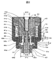
- FIG. 1 is a sectional view showing a structure of a fuel injection device according to one embodiment of the present invention, and is a longitudinal sectional view showing a cut surface parallel to a central axis 100a.
- FIG. 2 is an enlarged cross-sectional view of the electromagnetic drive unit 400 shown in FIG.
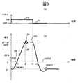
- FIG. 3 is a diagram for explaining the operation of the movable part.
- FIG. 3A shows the ON / OFF state of the injection command pulse
- FIG. 3B shows the displacement of the plunger rod 102 and the movable iron core 404 with the valve closed state of the plunger rod 102 being zero displacement.
- the fuel injection device 100 includes a fuel supply unit 200 that supplies fuel, a nozzle unit 300 that is provided with a valve unit 300a that allows or blocks fuel flow, and an electromagnetic drive unit that drives the valve unit 300a. 400.
- a fuel supply unit 200 that supplies fuel
- a nozzle unit 300 that is provided with a valve unit 300a that allows or blocks fuel flow
- an electromagnetic drive unit that drives the valve unit 300a. 400.
- an electromagnetic fuel injection device for an internal combustion engine using gasoline as fuel will be described as an example.
- the fuel supply part 200, the valve part 300a, the nozzle part 300, and the electromagnetic drive part 400 have indicated the applicable part with respect to the cross section described in FIG. 1, and do not show a single component.
- a fuel supply unit 200 is configured on the upper end side of the drawing, a nozzle unit 300 is configured on the lower end side, and an electromagnetic drive unit 400 is configured between the fuel supply unit 200 and the nozzle unit 300. ing. That is, the fuel supply unit 200, the electromagnetic drive unit 400, and the nozzle unit 300 are arranged in this order along the direction of the central axis 100a.
- the end of the fuel supply unit 200 opposite to the nozzle unit 300 is connected to a fuel pipe (not shown).
- the nozzle part 300 has an end opposite to the fuel supply part 200 in a mounting hole (insertion hole) formed in a not-shown intake pipe or a combustion chamber forming member (cylinder block, cylinder head, etc.) of the internal combustion engine. Inserted.
- the electromagnetic fuel injection device 100 is supplied with fuel from a fuel pipe through a fuel supply unit 200 and injects fuel from the tip of the nozzle unit 300 into the intake pipe or the combustion chamber. Inside the fuel injection device 100, a fuel passage 101 is provided so that fuel flows substantially along the direction of the central axis 100 a of the electromagnetic fuel injection device 100 from the end of the fuel supply unit 200 to the tip of the nozzle unit 300. (101a to 101f) are configured.
- the end portion or the end portion side of the fuel supply unit 200 positioned on the opposite side to the nozzle portion 300 is the base end portion or the base end at both ends in the direction along the central axis 100a of the fuel injection device 100.
- the end side or the end side of the nozzle part 300 located on the opposite side to the fuel supply unit 200 will be referred to as the end side or the front end side.
- the description will be given with “upper” or “lower” attached to each part constituting the electromagnetic fuel injection device. This is done for ease of explanation, and the mounting form of the electromagnetic fuel injection device for the internal combustion engine is not limited to the vertical direction.
- the fuel supply unit 200 includes a fuel pipe 201.
- a fuel supply port 201a is provided at one end (upper end) of the fuel pipe 201, and a fuel passage 101a is formed inside the fuel pipe 201 so as to penetrate in the direction along the central axis 100a.
- the other end (lower end) of the fuel pipe 201 is joined to one end (upper end) of the fixed iron core 401.
- An O-ring 202 and a backup ring 203 are provided on the outer peripheral side of the upper end portion of the fuel pipe 201.
- the O-ring 202 functions as a seal that prevents fuel leakage when the fuel supply port 201a is attached to the fuel pipe.
- the backup ring 203 is for backing up the O-ring 202.
- the backup ring 203 may be configured by laminating a plurality of ring-shaped members.
- a filter 204 that filters out foreign matters mixed in the fuel is disposed inside the fuel supply port 201a.
- the nozzle part 300 includes a nozzle body 300b, and a valve part 300a is formed at the tip (lower end) of the nozzle body 300b.
- the nozzle body 300b is a hollow cylindrical body and constitutes a fuel passage 101f on the upstream side of the valve portion 300a.
- a movable iron core receiving portion 311 is formed in the lower fuel passage portion 101 e of the electromagnetic drive portion 400.
- a tip seal 103 is provided on the outer peripheral surface of the tip of the nozzle body 300b to maintain airtightness when mounted on the internal combustion engine.
- the valve portion 300a includes an injection hole forming member 301, a guide portion 302, and a valve body 303 provided at one end portion (lower end side tip portion) of the plunger rod 102.
- the injection hole forming member 301 has a fuel passage portion 306 configured to form a gap with the valve body 303, a seat portion 304 that contacts the valve body 303 to seal the fuel, and a fuel injection in which the diameter of the injection hole for injecting fuel is ⁇ D. It consists of holes 305.
- the tip portion 310 of the injection hole forming member 301 includes a tip portion surface 310a that is a surface having a different angle from the sheet surface 304a and the central axis 100a, and a processing forming surface 310b that is slightly recessed toward the center. .
- the process formation surface 310b improves processability, and does not give a difference in the fuel flow in this invention by the presence or absence.
- the electromagnetic drive unit 400 includes a fixed iron core 401, a coil 402, a housing 403, a movable iron core 404, an intermediate member 414, a plunger cap 410, a first spring member 405, a third spring member 406, and a second. And a spring member 407.
- the fixed iron core 401 is also called a fixed core.
- the movable iron core 404 is called a movable core, a movable element or an armature.
- the fixed iron core 401 has a fuel passage 101c and a joint 401a with the fuel pipe 201 at the center.
- the outer peripheral surface 401b of the fixed core 401 is fitted and joined to the large-diameter inner peripheral portion 300c of the nozzle body 300b, and the outer peripheral surface 401e having a larger diameter than the outer peripheral surface 401b is fitted and joined to the outer peripheral side fixed core 401d.
- a coil 402 is wound around the outer periphery of the fixed iron core 401 and the large-diameter portion 300c of the cylindrical member.
- the housing 403 is provided so as to surround the outer peripheral side of the coil 402 and constitutes the outer periphery of the electromagnetic fuel injection device 100.
- the upper end side inner peripheral surface 403a of the housing 403 is connected to the outer peripheral surface 401f of the outer peripheral side fixed iron core 401d joined to the outer peripheral surface 401e of the fixed iron core 401.
- a movable iron core 404 is disposed on the lower end surface 401 g side of the fixed iron core 401.
- the upper end surface 404c of the movable iron core 404 is opposed to the lower end surface 401g of the fixed iron core 401 with a gap g2 in the closed state.
- the outer peripheral surface of the movable iron core 404 is opposed to the inner peripheral surface of the large diameter portion 300c of the nozzle body 300b with a slight gap, and the movable iron core 404 is centered on the inner side of the large diameter portion 300c of the cylindrical member. It is provided so as to be movable in a direction along 100a.
- a magnetic path is formed so that the magnetic flux circulates around the fixed iron core 401, the movable iron core 404, the housing 403, and the large-diameter portion 300c of the cylindrical member.
- the movable iron core 404 is attracted toward the fixed iron core 401 by a magnetic attractive force generated by a magnetic flux flowing between the lower end surface 401 g of the fixed iron core 401 and the upper end surface 404 c of the movable iron core 404.
- a recess 404b that is recessed from the upper end surface 404c side to the lower end surface 404a side.
- a fuel passage hole 404d is formed in the bottom surface of the upper end surface 404c and the recess 404b as a fuel passage 101d that penetrates to the lower end surface 404a side in the direction along the central axis 100a.
- a through hole 404e that penetrates to the lower end surface 404a side in the direction along the central axis 100a is formed on the bottom surface of the recess 404b.
- the plunger rod 102 is provided so as to be inserted through the through hole 404e.
- a plunger cap 410 is fixed to the plunger rod 102 by fitting, and has a large diameter portion 102a.
- the intermediate member 414 is a cylindrical member having a concave portion that forms a step on the inner and outer periphery, the inner peripheral surface 414a is in contact with the plunger rod large diameter portion 102a upper surface 102b, and the outer peripheral surface 414b is the recess of the movable iron core. It is in contact with the bottom surface 404b ′. There is a gap g1 between the lower surface 102c of the large-diameter portion and the bottom surface 404b 'of the movable core recess 404b.
- a movable iron core receiving part 311 is formed from the outer peripheral side of the nozzle body 300b to the inner peripheral side cavity to the inner peripheral side to the diameter part of 311a.
- the upper end portion of the first spring member 405 is in contact with the lower end surface of the spring force adjusting member 106, and the lower end portion of the first spring member 405 is in contact with the upper spring receiver 410 a of the plunger cap 410 and the plunger cap 410 is interposed through the plunger cap 410.
- the rod 102 is urged downward.
- the upper end portion of the third spring member 406 contacts the lower spring receiving portion 410b of the plunger cap 410, and the lower end portion of the third spring member 406 contacts the upper surface 414c of the intermediate member 414 and attaches the intermediate member 414 downward. It is fast.
- the upper end portion of the second spring 407 is in contact with the lower surface 404a of the movable core 404, and the lower end portion of the second spring 407 is in contact with the step portion 300d of the nozzle body 300b to urge the movable core 404 upward.
- the coil 402 is assembled on the outer peripheral side of the fixed iron core 401 and the cylindrical member large-diameter portion 300b in a state of being wound around a bobbin, and a resin material is molded around it.
- a connector 105 having a terminal 104 drawn out from the coil 402 is integrally formed by a resin material used for the mold.
- FIG. 2 is an enlarged view of the electromagnetic drive unit 400
- FIG. 3 which explains the operation of the movable portion
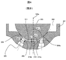
- FIG. 4 which is an enlarged view of the valve portion 303a.
- the biasing force of the third spring member 406 is increased from the biasing force of the first spring member 405 and the second spring member 407 that biases the plunger rod 102 in the valve closing direction.
- the pulled force causes the plunger rod 102 to contact the seat portion 304 and close the valve.
- This state is called a closed valve stationary state.
- the movable iron core 404 is in contact with the outer peripheral side step 414b of the intermediate member 414 and is disposed at the valve closing position.
- the gap related to the movable part related to the valve opening operation is configured as follows.
- a gap g ⁇ b> 2 is provided between the upper end surface 404 c of the movable iron core 404 and the lower end surface 401 g of the fixed iron core 401.
- the relationship between g1 and g2 is configured as g2> g1.
- a magnetomotive force is generated by the electromagnet constituted by the fixed iron core 401, the coil 402, and the housing 403.
- a magnetic flux circulating around a magnetic path constituted by the fixed iron core 401, the housing 403, the large diameter portion 300 d of the nozzle body, and the movable iron core 404 configured to surround the coil 402 flows.
- a magnetic attractive force acts between the upper end surface 404 c of the movable iron core 404 and the lower end surface 401 g of the fixed iron core 401, and the movable iron core 404 and the intermediate member 414 are displaced toward the fixed iron core 401.
- the movable iron core 404 is displaced by g1 until it comes into contact with the lower surface 102c of the large-diameter portion of the plunger rod (404D1). At this time, the plunger rod 102 does not move (102D1).
- the plunger rod 102 receives an impact force from the movable iron core 404, and the plunger rod 102 is separated from the seat portion 304. As a result, a gap is formed in the seat portion, and the fuel passage is opened. In response to the impact force, the valve starts to open, so that the plunger rod 102 rises sharply (3A).
- the plunger rod 102 is displaced by g2-g1, and when the upper surface 404c of the movable iron core 404 abuts the lower surface 401g of the fixed iron core 401 at the timing t2, the plunger rod 102 is displaced upward (3B) and is movable.
- the iron core 404 is displaced downward (3B ′), and after contacting again, the iron core 404 is stabilized to the displacement of g2-g1 (307) (3C).
- the magnetic force starts to disappear, and the valve closing operation is performed by the biasing force of the downward spring.
- the plunger rod comes into contact with the seat portion 304 to complete the valve closing ( 102D2).
- the movable iron core 404 moves to the initial position g1 after closing the valve (404D2), and further moves downward, and then stops at the position of g1 (404D3).
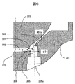
- FIG. 4 illustrates a case where the valve body 303 is closed.
- a seat surface 304a having a seat portion 304 is formed with an angle ⁇ 1 between the seat surface 304a and the central axis 100a of the fuel injection device.
- the fuel injection device front end portion 310a of the injection hole forming member 301 is formed with an angle ⁇ 2 between the central shafts 100a of the fuel injection device.
- a gap L1 is formed between the distal end surface 311 of the valve body 303 and the injection hole forming member surface 310a when the valve is closed.
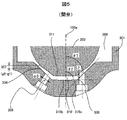
- FIG. 5 shows a diagram when the valve body 303 is opened.
- a displacement 307 (g2-g1 in FIG. 3) is formed between the valve body 303 and the seat portion 304.
- the end 308 on the downstream side of the fuel injection hole and the point of the valve body 303 corresponding to the axial direction have a gap L2.
- the injection hole forming member 301 is inserted and fixed in a concave inner peripheral surface 300ba formed at the tip of the nozzle body 300b. At this time, the outer periphery of the front end surface of the injection hole forming member 301 and the inner periphery of the front end surface of the nozzle body 300b are welded to seal the fuel.
- the guide portion 302 is on the inner peripheral side of the injection hole forming member 301, has a slight gap while being a guide surface with the distal end side (lower end side) of the plunger rod 102, and in a direction along the central axis 100a (open / close valve direction). It serves as a guide when the plunger rod 102 moves.
- a fuel injection device including a valve body 303 and a seat member (injection hole forming member 301) having a seat portion 304 on which the valve body 303 is seated and having a fuel injection hole 305 formed on the downstream side of the seat portion 304.
- the soot sheet member (injection hole forming member 301) is formed so that the gap between the opposing valve body 303 in all the regions downstream of the fuel injection hole 305 is smaller than the diameter ⁇ D of the fuel injection hole 305.
- a maximum clearance is formed between the tip end surface 311 of the valve body 303 and the injection hole forming member surface 310a. This gap is larger than L1.
- the maximum gap is formed to be smaller than the diameter ⁇ D of the fuel injection hole 305.
- the gap L2 in the central axis direction between the portion 308 and the facing portion of the valve body 303 facing the most downstream end portion 308 is configured to be larger.
- the gap L1 that opposes the injection hole forming member 301 in the region on the fuel injection device shaft 100a side of the fuel injection hole 305 is made smaller than the diameter diameter ⁇ D of the fuel injection hole 305 in this way.
- the fuel flow 502 generated in the center of the fuel injection device is a high-speed flow in the middle of the valve closing due to the narrow gap and the downward displacement of the valve body 303 in the middle of the valve closing. Become. Thereby, the speed of the flow 501 into the fuel injection hole 305 is also increased. For this reason, after the valve is closed, the amount of fuel flowing in is small and there is little sag. Therefore, it is possible to reduce the fuel adhesion which becomes a deposit which becomes a soot generation element.
- a gap L1 that opposes the injection hole forming member 301 in the region of the fuel injection hole 305 on the side of the fuel injection device shaft 100a has a lower end portion 308 of the fuel injection hole 305 at the time of valve opening and Since it is made smaller than the gap L2 between the facing portion, the fuel flow 502 generated at the tip portion 310 flows into the fuel injection hole 305 without increasing the flow path area. Since the flow is 501, the fuel runs out well after the valve is closed, and there is little back droop. As a result, the adhesion of fuel that becomes a deposit that becomes a soot generation element is reduced.
- the gap L1 that opposes the injection hole forming member 301 in the region of the fuel injection hole 305 on the fuel injection device shaft 100a side is configured to be substantially constant in the region of the injection hole 305 from the fuel injection device central shaft 100a. Is done. That is, as shown in FIG. 4, in the valve-closed state, the seat member (injection hole forming member 301) and the valve body 303 are the gaps between the valve bodies 303 facing each other in the entire region on the downstream side of the fuel injection hole 305. Is configured to be substantially constant. As a result, the fuel flow 502 generated at the distal end portion 310 is reduced in pressure loss caused by expansion / contraction of the flow path on the way, and flows into the fuel injection hole 305 at a high speed.
- the flow 501 flows into the fuel injection hole 305, the fuel can be cut well even after the valve is closed, and the rear sagging is small. As a result, the adhesion of fuel that becomes a deposit that becomes a soot generation element is reduced.
- the front end portion (tip end surface 311) of the seat member is configured in a substantially linear shape in the direction orthogonal to the axial direction of the valve body 303 on the downstream side of the fuel injection hole 305. Is done.
- tip part surface 310a) is also comprised by the substantially linear shape in the direction orthogonal to the axial direction of the central axis 100a of the valve body 303.
- the valve body 303 has a substantially spherical shape on the upstream side of the valve body distal end portion (tip portion surface 311).
- the sheet member (injection hole forming member 301) has an angle ⁇ 1 formed by the sheet surface 304a and the central axis 100a smaller than an angle ⁇ 2 formed by the injection hole forming member tip end surface 310a and the central axis 100a of the fuel injection device. Configured. As a result, the gap L1 formed by both can be reduced, and adjustment by processing of the valve body 303 and the injection hole forming portion 301 can be facilitated, so that the fuel injection device can be supplied at low cost. become. In the present invention, since the main purpose is to have a configuration in which the gap between the two becomes narrow, it is conceivable to determine the angle in consideration of ease of processing.
- the diameter of the fuel injection hole is described as being the same, but is not limited thereto.
- the closed state gap g3 between the movable iron core 404 and the movable iron core receiving part 311 in the valve-closed state is obtained by processing the nozzle body 00b. It is possible to make a decision, and it is possible to improve the performance by a simple method without adding parts.
- the outer diameter 414D of the intermediate member is smaller than the inner diameter 401D of the fixed core. Therefore, when assembling the fuel injection device, after determining the gap g1 by the step height 414h of the intermediate member and the height h of the plunger rod large diameter portion, the spring force adjusting member 106 and the first spring member 405 are inserted. In this state, the plunger cap 410, the plunger rod 102, the third spring member 406, and the intermediate member 414 can be integrated in advance into the fuel injection device. g1 can be managed.
- the large-diameter portion 414D of the intermediate member 414 is made smaller than the inner diameter 401D of the fixed iron core 401.
- the outermost diameter of the plunger cap 410 may be made smaller than the inner diameter 401D of the fixed iron core 401.
- the intermediate member 414 can be disposed on the lower side, the length of the plunger rod 102 in the vertical direction can be shortened, and the highly accurate plunger rod 102 is configured. Because it becomes possible to do.
- the sheet surface 304 and the injection hole aperture surface 304a are the same surface, but are not limited thereto.
- the injection hole opening surface 304a may be configured to have a surface that is recessed downstream of the sheet surface 304.
- FIGS. A second embodiment according to the present invention will be described with reference to FIGS.
- components having the same reference numerals as those in the first embodiment are not different in configuration, operation, and effect, and thus description thereof is omitted.
- the inlet of the fuel injection hole 2305 is perforated so as to straddle the injection hole opening surface 304a and the tip end surface 310a of the injection hole forming member 301. That is, the injection hole opening surface 304a formed substantially parallel to the seat surface 304 and the tip end surface 310a of the injection hole forming member 301 formed substantially orthogonal to the axial direction of the central axis 100a are the fuel injection holes. It is comprised so that it may cross in the inner peripheral side of the entrance surface of 2305.
- the flow 2502 generated during the closing of the valve body 303 is formed in the injection hole 2305 by forming a high-speed flow 2502 due to the narrow gap between the valve body 303 and the injection hole forming member tip 310. Since the flowing flow 2501 flows directly into the injection hole 2305 without a step or the like, a decrease in speed due to the pressure loss generated in the fuel flow path is reduced as compared with the case of the first embodiment.
- this invention is not limited to each above-mentioned Example, Various modifications are included.
- the above-described embodiments have been described in detail for easy understanding of the present invention, and are not necessarily limited to those having all the configurations.
- a part of the configuration of one embodiment can be replaced with the configuration of another embodiment, and the configuration of another embodiment can be added to the configuration of one embodiment.
Landscapes
- Engineering & Computer Science (AREA)
- General Engineering & Computer Science (AREA)
- Mechanical Engineering (AREA)
- Chemical & Material Sciences (AREA)
- Combustion & Propulsion (AREA)
- Physics & Mathematics (AREA)
- Electromagnetism (AREA)
- Fuel-Injection Apparatus (AREA)
Abstract
弁体閉弁時に発生する燃料の後だれを低減可能な構造を提供する。上記目的を達成するために、弁体と、弁体が着座するシート部を有し、前記シート部の下流側に燃料噴射孔が形成されたシート部材とを備えた燃料噴射装置において、シート部材は燃料噴射孔の下流側の全ての領域において対向する弁体との間の隙間が燃料噴射孔の直径よりも小さくなるようにした。
Description
本発明は、内燃機関に用いられ、主に燃料を噴射する燃料噴射装置に関する。
本技術分野の背景技術として、特開2011-153548号公報(特許文献1)がある。この公報には、燃料噴射ノズルにおいて、サック室内の燃料流れにおける運動エネルギーの減少を抑制させ、高貫徹力を実現するとともに微粒化を促進できることが開示されている。
燃料噴射装置では、噴霧の微粒化だけではなく、噴射終了後の流れ込みを考慮しながら、エンジンから排出されるすす成分の低減が必要である。すす成分の生成には燃料噴射終了時の燃料の後だれが影響を与える。そのため、閉弁時における燃料の流れ込みを考慮したノズル形状が重要である。
特許文献1では、弁体の動作中に関する課題開示はなく、微粒化性能を向上させることは可能になるが、閉弁時の燃料の後だれを低減することは達成し得ない。
そこで、本発明は、弁体閉弁時に発生する燃料の後だれを低減可能な構造を提供することを目的としている。
上記目的を達成するために、弁体と、弁体が着座するシート部を有し、前記シート部の下流側に燃料噴射孔が形成されたシート部材とを備えた燃料噴射装置において、シート部材は燃料噴射孔の下流側の全ての領域において対向する弁体との間の隙間が燃料噴射孔の直径よりも小さくなるようにした。
本発明の構成によれば、閉弁時に発生する弁動作により、燃料が噴射孔から排出されやすく、後だれを低減することができる。
以下、本発明に係る実施例について説明する。
図1及び図7を用いて、本発明に係る第1実施例である燃料噴射装置100の構成について説明する。図1は本発明の1実施例に係る燃料噴射装置の構造を示す断面図であり、中心軸線100aに平行な切断面を示す縦断面図である。図2は図1に示す電磁駆動部400を拡大して示す断面図である。図3は可動部の動作を説明した図である。図3(a)は噴射指令パルスのON-OFF状態を示し、(b)はプランジャロッド102の閉弁状態を変位0として、プランジャロッド102と可動鉄心404の変位を示している。
燃料噴射装置100は、燃料を供給する燃料供給部200と、燃料の流通を許したり遮断したりする弁部300aが先端部に設けられたノズル部300と、弁部300aを駆動する電磁駆動部400とで、構成される。本実施例では、ガソリンを燃料とする内燃機関用の電磁式燃料噴射装置を例にとり、説明する。なお、燃料供給部200、弁部300a、ノズル部300及び電磁駆動部400は、図1に記載した断面に対して該当する部分を指示しており、単一の部品を示す物ではない。
本実施例の燃料噴射装置100では、図面の上端側に燃料供給部200が、下端側にノズル部300が構成され、燃料供給部200とノズル部300との間に電磁駆動部400が構成されている。すなわち、中心軸線100a方向に沿って、燃料供給部200、電磁駆動部400及びノズル部300がこの順に配置されている。
燃料供給部200は、ノズル部300に対して反対側の端部が図示しない燃料配管に連結される。ノズル部300は、燃料供給部200に対して反対側の端部が、図示しない吸気管或いは内燃機関の燃焼室形成部材(シリンダブロック、シリンダヘッド等)に形成された取付穴(挿入孔)に挿入される。電磁式燃料噴射装置100は燃料供給部200を通じて燃料配管から燃料の供給を受け、ノズル部300の先端部から吸気管或いは燃焼室内に燃料を噴射する。燃料噴射装置100の内部には、燃料供給部200の前記端部からノズル部300の先端部まで、燃料がほぼ電磁式燃料噴射装置100の中心軸線100a方向に沿って流れるように、燃料通路101(101a~101f)が構成されている。
以下の説明においては、燃料噴射装置100の中心軸線100aに沿う方向の両端部について、ノズル部300に対して反対側に位置する燃料供給部200の端部或いは端部側を基端部或いは基端側と呼び、燃料供給部200に対して反対側に位置するノズル部300の端部或いは端部側を先端部或いは先端側と呼ぶことにする。また、図1の上下方向を基準として、電磁式燃料噴射装置を構成する各部に「上」又は「下」を付けて説明する。
これは、説明を分かり易くするために行うものであり、内燃機関に対する電磁式燃料噴射装置の実装形態をこの上下方向に限定するものではない。
これは、説明を分かり易くするために行うものであり、内燃機関に対する電磁式燃料噴射装置の実装形態をこの上下方向に限定するものではない。
以下、燃料供給部200、電磁駆動部400及びノズル部300の構成について、詳細に説明する。
燃料供給部200は、燃料パイプ201によって構成される。燃料パイプ201の一端部(上端部)には、燃料供給口201aが設けられ、燃料パイプ201の内側には燃料通路101aが中心軸線100aに沿う方向に貫通するように形成されている。燃料パイプ201の他端部(下端部)は固定鉄心401の一端部(上端部)に接合されている。
燃料供給部200は、燃料パイプ201によって構成される。燃料パイプ201の一端部(上端部)には、燃料供給口201aが設けられ、燃料パイプ201の内側には燃料通路101aが中心軸線100aに沿う方向に貫通するように形成されている。燃料パイプ201の他端部(下端部)は固定鉄心401の一端部(上端部)に接合されている。
燃料パイプ201の上端部の外周側には、Oリング202とバックアップリング203とが設けられている。
Oリング202は、燃料供給口201aが燃料配管に取り付けられた際に、燃料漏れを防止するシールとして機能する。また、バックアップリング203はOリング202をバックアップするためのものである。バックアップリング203は複数のリング状部材が積層されて構成される場合もある。燃料供給口201aの内側には燃料に混入した異物を濾しとるフィルタ204が配設されている。
ノズル部300は、ノズル体300bを備え、ノズル体300bの先端部(下端部)に弁部300aが構成されている。ノズル体300bは中空の筒状体であり、弁部300aの上流側に燃料通路101fを構成している。また、電磁駆動部400の下方燃料通路部101e部に可動鉄心受部311が構成されている。尚、ノズル体300bの先端部外周面には、内燃機関に搭載される際に気密を維持するチップシール103が設けられている。
弁部300aは、噴射孔形成部材301と、ガイド部302と、プランジャロッド102の一端部(下端側先端部)に設けられた弁体303とを備えている。 噴射孔形成部材301には弁体303と隙間をなして構成される燃料通路部306、弁体303と接して燃料を封止するシート部304、燃料を噴射する噴射孔径がφDとなる燃料噴射孔305から構成される。
噴射孔形成部材301における先端部310には、シート面304aと中心軸100aと角度の異なる面となる先端部面310a及び更に中央寄りに僅かに凹み部となる加工形成面310bが構成されている。なお、加工形成面310bは加工容易性を向上させるものであり、その有無により本発明における燃料流れに差を与えるものではない。
電磁駆動部400は、固定鉄心401と、コイル402と、ハウジング403と、可動鉄心404と、中間部材414と、プランジャキャップ410と、第1ばね部材405と、第3ばね部材406と、第2ばね部材407とで構成されている。固定鉄心401は固定コアとも呼ばれる。可動鉄心404は可動コア、可動子やアーマチャと呼ばれる。
固定鉄心401は、中心部に燃料通路101c、燃料パイプ201との接合部401aを有する。固定鉄心401の外周面401bはノズル体300bの大径内周部300cと嵌合接合され、外周面401bよりも大径となる外周面401eにて、外周側固定鉄心401dと嵌合接合されている。固定鉄心401及び筒状部材の大径部300cの外周側にはコイル402が巻回されている。
ハウジング403はコイル402の外周側を囲むように設けられ、電磁式燃料噴射装置100の外周を構成している。ハウジング403の上端側内周面403aは固定鉄心401の外周面401eと接合される、外周側固定鉄心401dの外周面401fに接続されている。
固定鉄心401の下端面401g側には、可動鉄心404が配置されている。可動鉄心404の上端面404cは、閉弁状態において、固定鉄心401の下端面401gと隙間g2を有して対向している。また、可動鉄心404の外周面はノズル体300bの大径部300cの内周面と僅かな隙間を介して対向しており、可動鉄心404は筒状部材の大径部300cの内側で中心軸線100aに沿う方向に移動可能に設けられている。
固定鉄心401、可動鉄心404、ハウジング403、筒状部材の大径部300cへ、磁束が周回するように磁路が形成される。固定鉄心401の下端面401gと可動鉄心404の上端面404cとの間を流れる磁束によって発生する磁気吸引力によって可動鉄心404を固定鉄心401方向へ吸引する。
可動鉄心404の中央部には、上端面404c側から下端面404a側に窪んだ凹部404bが形成されている。上端面404cと凹部404bの底面には、中心軸線100aに沿う方向に下端面404a側まで貫通する燃料通路101dとして燃料通路孔404dが形成されている。また、凹部404bの底面には、中心軸線100aに沿う方向に下端面404a側まで貫通する貫通孔404eが構成されている。貫通孔404eを挿通するようにプランジャロッド102が設けられている。プランジャロッド102には、プランジャキャップ410が嵌合により固定されており、太径部102aを有する。中間部材414は、内外周に段差となる凹部を有する筒状部材であり、内周側の面414aをプランジャロッド太径部102a上面102bと当接し、外周側の面414bを可動鉄心の凹部の底面404b’と当接している。太径部の下面102cと可動鉄心凹部404bの底面404b’の間には隙間g1を有している。中間部材414の凹部段差の高さ414hからプランジャロッド太径部の上面102bと下面102cのなす高さhを引いた長さが、上記隙間g1となっている。可動鉄心404の下方にはノズル体300bの一部でありノズル体300bの外周側より内周側空洞部まで内周側へ311aの径部まで可動鉄心受部311が構成されている。
第1ばね部材405の上端部は、ばね力調整部材106の下端面に当接し、第1ばね部材405の下端部は、プランジャキャップ410の上部ばね受け410aに当接しプランジャキャップ410を介し、プランジャロッド102を下方に付勢している。第3ばね部材406の上端部は、プランジャキャップ410の下方ばね受け部410bと当接し、第3ばね部材406の下端部は、中間部材414の上面414cに当接し中間部材414を下方向に付勢している。第2ばね407の上端部は、可動鉄心404の下面404aに当接し、第2ばね407の下端部はノズル体300bの段差部300dと当接し可動鉄心404を上方向に付勢している。
コイル402はボビンに巻かれた状態で固定鉄心401及び筒状部材大径部300bの外周側に組み付けられ、その周囲には樹脂材がモールドされている。このモールドに使用される樹脂材により、コイル402から引き出されたターミナル104を有するコネクタ105が一体的に成形されている。
次に本実施例における燃料噴射装置100の動作について説明する。主に電磁駆動部400の拡大図である図2と可動部の動作を説明した図3及び弁部303aの拡大図示した図4を用いて説明する。
コイル402に通電されていない閉弁状態では、プランジャロッド102を閉弁方向に付勢する第1ばね部材405と、第2ばね部材407との付勢力から第3のばね部材406の付勢力を引いた力により、プランジャロッド102がシート部304に当接して閉弁している。この状態を閉弁静止状態という。このとき、可動鉄心404は中間部材414の外周側段差部414bと当接し閉弁位置に配置されている。なお、本実施例の燃料噴射装置の閉弁状態において、開弁動作に関わる、可動部品に関係する隙間は下記のように構成されている。可動鉄心404の上端面404cと固定鉄心401の下端面401gとの間には、隙間g2を有する。可動鉄心404の凹部404bの平面404b’とプランジャロッド太径部の下面102cとの間には隙間g1を有する。g1とg2の関係は、g2>g1と構成されている。
コイル402への通電後(P1)、固定鉄心401、コイル402及びハウジング403によって構成された電磁石により起磁力が発生する。この起磁力により、コイル402を囲むように構成された固定鉄心401、ハウジング403、ノズル体の太径部300d、可動鉄心404によって構成される磁路を周回する磁束が流れる。このとき、可動鉄心404の上端面404cと固定鉄心401の下端面401gとの間に磁気吸引力が作用し、可動鉄心404と中間部材414が固定鉄心401に向けて変位する。その後、可動鉄心404は、プランジャロッドの太径部下面102cに当接するまでg1だけ変位する(404D1)。なお、この際、プランジャロッド102は動かない(102D1)。
その後、t1のタイミングにおいて可動鉄心404がプランジャロッドの太径部下面102cに当接すると、プランジャロッド102は可動鉄心404から衝撃力を受け引き上げられ、プランジャロッド102はシート部304から離れる。これによりシート部に隙間が構成され、燃料通路が開く。衝撃力を受け開弁を開始するため、プランジャロッド102の立ち上がりが急峻になる(3A)。
その後、プランジャロッド102が、g2-g1だけ変位し、t2のタイミングで可動鉄心404の上面404cが、固定鉄心401の下面401gと当接すると、プランジャロッド102は上方へ変位し(3B)、可動鉄心404は下方へ変位する(3B’)し、再度接触した後はg2-g1(307)の変位に安定する(3C)。
タイミングt3において、コイル402への通電が遮断(P2)されると、磁気力が消失しはじめ、下方向のばねの付勢力により閉弁動作をする。閉弁途中に変位の中間付近の変位位置307aを通過し、t4のタイミングにてプランジャロッド102の変位が0になった後は、プランジャロッドはシート部304に当接して閉弁を完了する(102D2)。
可動鉄心404は、閉弁後に初期位置であるg1まで移動した後(404D2)さらに下方向へ変位した後、g1の位置に停止する(404D3)。
可動鉄心404は、閉弁後に初期位置であるg1まで移動した後(404D2)さらに下方向へ変位した後、g1の位置に停止する(404D3)。
図4は、弁体303が閉弁している場合の図が描かれている。シート部304を有するシート面304aが燃料噴射装置の中心軸100aとの間に角度Θ1を有して形成されている。噴射孔形成部材301の燃料噴射装置先端部310aは燃料噴射装置の中心軸100aの間に角度Θ2を成して構成されている。弁体303の先端部面311と噴射孔形成部材面310aの間には閉弁状態においてL1の隙間が構成されている。
図5は、弁体303が開弁している場合の図が描かれている。弁体303とシート部304の間に変位307(図3におけるg2-g1)が構成されている。開弁している状態において、燃料噴射孔下流側の端部308とその軸方向に対応する弁体303の点はL2となる隙間を有し構成されている。
噴射孔形成部材301は、ノズル体300bの先端部に形成された凹部内周面300baに挿入されて固定されている。このとき、噴射孔形成部材301の先端面の外周とノズル体300bの先端面内周とが溶接され、燃料をシールする。
ガイド部302は噴射孔形成部材301の内周側にあり、プランジャロッド102の先端側(下端側)とガイド面となりながら僅かな隙間を有し、中心軸線100aに沿う方向
(開閉弁方向)にプランジャロッド102が移動する際の案内となる。
(開閉弁方向)にプランジャロッド102が移動する際の案内となる。
弁体303と、弁体303が着座するシート部304を有し、シート部304の下流側に燃料噴射孔305が形成されたシート部材(噴射孔形成部材301)とを備えた燃料噴射装置において、 シート部材(噴射孔形成部材301)は燃料噴射孔305の下流側の全ての領域において対向する弁体303との間の隙間が燃料噴射孔305の直径φDよりも小さくなるように形成された。なお、本実施例では燃料噴射孔305の下流側において、弁体303の先端部面311と噴射孔形成部材面310aの間に閉弁状態で最大となる隙間が形成される。この隙間はL1よりも大きい。そして、この最大隙間が燃料噴射孔305の直径φDよりも小さくなるように形成する。
また、シート部材(噴射孔形成部材301)は燃料噴射孔305の下流側の全ての領域において対向する弁体303との間の最大隙間が開弁時における燃料噴射孔305の入口面と該入口面に対向する弁体の対向部との間の隙間(燃料噴射孔下流側の端部308からの軸方向隙間L2)よりも小さくなる。
具体的には、弁体303の先端部面311とシート部材先端部(噴射孔形成部材面310a)との間の最大隙間に対して開弁時における燃料噴射孔305の入口面の最下流端部308と最下流端部308に対向する弁体303の対向部との間の中心軸方向における隙間L2の方が大きくなるように構成される。
本実施例では、このように、噴射孔形成部材301を燃料噴射孔305の燃料噴射装置軸100a側の領域において対向する隙間L1が燃料噴射孔305の直径径φDよりも小さくなるようにした。これにより、図6に示すように、燃料噴射装置中央部において発生する燃料流れ502は、隙間が狭い事と閉弁途中に弁体303の下方への変位によって、閉弁途中に高速な流れとなる。それにより燃料噴射孔305への流れ込み501の速度も速くなる。そのため、閉弁した後には、流れ込む燃料が少なく、後ダレは少ない。したがって、すすの生成要素となるデポジットになる燃料付着を低減することが可能である。
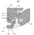
一方、図7に示すように、本実施例とは異なり噴射孔7305よりも中央寄り7100aの弁体7303と噴射孔形成部材7301の隙間が大きい場合には、下流側隙間が閉弁途中において、隙間が大きい。したがって、燃料の戻り流れ702が発生するのが遅く、更には、噴射孔下端側に発生する流れ701の流速も遅く流れ込みが緩やかになる。そのため、閉弁した後も燃料が排出しきれず、後ダレとなり、すすの生成要素となるデポジット抑制につながる燃料付着となる虞がある。
また、噴射孔形成部材301を燃料噴射孔305の燃料噴射装置軸100a側の領域において対向する隙間L1が、開弁時における燃料噴射孔305の下端部308とその部位に対向する弁体303の対向部との間の隙間L2よりも小さくなるようにしているために、先端部310で発生する燃料流れ502対して、流路面積が拡大することなく高速なまま、燃料噴射孔305へ流入する流れ501になるため、閉弁をした後も燃料の切れが良く、後ダレは少ない。そのため、すすの生成要素となるデポジットになる燃料付着が低減される。
また、噴射孔形成部材301を燃料噴射孔305の燃料噴射装置軸100a側の領域において対向する隙間L1が、噴射孔305の燃料噴射装置中心軸100aよりの領域において、ほぼ一定となるように構成される。すなわち、図4に示すように閉弁状態において、シート部材(噴射孔形成部材301)と弁体303とは燃料噴射孔305の下流側の全ての領域において対向する弁体303との間の隙間がほぼ一定となるように構成される。
これにより、先端部310で発生する燃料流れ502が、途中の流路の拡大縮小によって発生する圧力損失が低減され、高速なまま燃料噴射孔305に流入する。したがって、燃料噴射孔305へ流入する流れ501になるため、閉弁をした後も燃料の切れが良く、後ダレは少ない。そのため、すすの生成要素となるデポジットになる燃料付着が低減される。
これにより、先端部310で発生する燃料流れ502が、途中の流路の拡大縮小によって発生する圧力損失が低減され、高速なまま燃料噴射孔305に流入する。したがって、燃料噴射孔305へ流入する流れ501になるため、閉弁をした後も燃料の切れが良く、後ダレは少ない。そのため、すすの生成要素となるデポジットになる燃料付着が低減される。
さらに、本実施例では図4、5に示すように、シート部材先端部(先端部面311)は燃料噴射孔305の下流側において弁体303の軸方向と直交する方向に略直線形状に構成される。そしてシート部材先端部(先端部面310a)と対向する弁体先端部(先端部面311)も弁体303の中心軸100aの軸方向と直交する方向に略直線形状に構成される。また弁体303は、弁体先端部(先端部面311)よりも上流側がほぼ球面形状にて構成される。
シート部材(噴射孔形成部材301)は、シート面304aと中心軸100aの成す角度Θ1が、噴射孔形成部材先端部面310aと燃料噴射装置の中心軸100aの成す角度Θ2よりも小さくなるように構成された。これにより、双方によって構成される隙間L1を小さくする事が出来、弁体303及び噴射孔形成部301の加工による調整を容易にする事が出来るため、燃料噴射装置の低コストでの供給が可能になる。なお、本発明においては、双方の隙間が狭くなる構成となる事が主たる目的であるため加工の容易性を考慮して角度を決める事が考えられる。
また、本実施例においては、燃料噴射孔の径は同一として記載したが、これに限定されることは無い。
本実施例の構成において、可動鉄心受部311がノズル体300bと一体であることにより、ノズル体00bの加工により、閉弁状態における可動鉄心404と可動鉄心受部311の閉弁状態隙間g3を決定する事が可能であり、部品の追加等なく簡易な方法で性能を向上させる事が可能となる。
また、本実施例の構成において、中間部材の外径414Dは、固定鉄心の内径401Dよりも小さくしている。そのために、燃料噴射装置を組立時、隙間g1を中間部材の段差高さ414hとプランジャロッド太径部の高さhとで決めた後に、ばね力調整部材106と第1のばね部材405が挿入されていない状態で、プランジャキャップ410、プランジャロッド102、第3のばね部材406、中間部材414を予め一体にして燃料噴射装置内に組み入れることができるために、組立を容易にしながらも安定した隙間g1の管理が可能となる。本実施例においては、中間部材414の太径部414Dが固定鉄心401の内径401Dよりも小さくなるようにしたが、予め組立てる部材の最外径が小さくなっていればよく、プランジャキャップ410の最外径が中間部材の最外径414Dよりも大きい場合は、前記プランジャキャップ410の最外径を固定鉄心401の内径401Dよりも小さくすれば良い。
なお、本実施例において、可動鉄心凹部404bが無く404cと同一の面であっても、本実施例と同一の作用効果を得ることが出来る。可動鉄心の凹部404bを設けることによって、中間部材414をより下側に配置する事が可能となり、プランジャロッド102の上下方向の長さを短くする事が可能となり、精度の良いプランジャロッド102を構成する事が可能になるためである。
なお、本発明において、シート面304と噴射孔開孔面304aは同一面であるが、これに限られることはない。例えば、噴射孔開孔面304aが、シート面304よりも下流側に凹んだ面を有して構成されていてもよい。このようにすることにより、燃料噴射孔305の長さを変更することも可能になり、噴射孔形成部301の設計自由度が向上する。
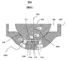
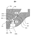
図8乃至9を用いて、本発明に関わる第2の実施例について説明する。図中、第1実施例と付与される符号が同じ部品については構成、作用、効果に差異はないため説明を省略する。
第1の実施例との差異は、燃料噴射孔2305の入口が噴射孔開孔面304aと噴射孔形成部材301の先端部面310aを跨ぐように穿孔されている。つまり、シート面304とほぼ並行に形成される噴射孔開孔面304aと、中心軸100aの軸方向とほぼ直交して形成される噴射孔形成部材301の先端部面310aとが、燃料噴射孔2305の入口面の内周側において交わるように構成される。この構成とする事により、弁体303の閉弁の途中で発生する流れ2502は弁体303と噴射孔形成部材先端部310の隙間が狭い事により、高速な流れ2502を形成し噴射孔2305に流れ込む流れ2501においても噴射孔2305へ段差などは無く直接流れ込むため、実施例1の場合よりも燃料流路中に発生する圧力損失に寄る速度の低下を低減する。
よって、閉弁した後には、流れ込む燃料が少なく、後ダレは少ない。そのため、すすの生成要素となるデポジットになる燃料付着が低減される。また、噴射孔2305に対して、上流側から流入する流れ2503も、シート部304より中央寄りにすることが可能であるため、流れの分布が安定した状態で流れ込む事が可能になるため、流れ込みのばらつきが低減され、後だれが低減することになる。
なお、本発明は上記した各実施例に限定されるものではなく、様々な変形例が含まれる。例えば、上記した実施例は本発明を分かりやすく説明するために詳細に説明したものであり、必ずしも全ての構成を備えるものに限定されるものではない。また、ある実施例の構成の一部を他の実施例の構成に置き換えることが可能であり、また、ある実施例の構成に他の実施例の構成を加えることも可能である。また、各実施例の構成の一部について、他の構成の追加・削除・置換をすることが可能である。
100・・・燃料噴射装置
101・・・燃料通路
102・・・プランジャロッド
200・・・燃料供給部
300・・・ノズル部
302・・・ガイド部
303・・・弁体
304・・・シート部
305・・・燃料噴射孔
306・・・流路部
400・・・電磁駆動部
401・・・固定鉄心
402・・・コイル
403・・・ハウジング
404・・・可動鉄心
405・・・第1ばね部材
406・・・第3ばね部材
407・・・第2ばね部材
414・・・中間部材
101・・・燃料通路
102・・・プランジャロッド
200・・・燃料供給部
300・・・ノズル部
302・・・ガイド部
303・・・弁体
304・・・シート部
305・・・燃料噴射孔
306・・・流路部
400・・・電磁駆動部
401・・・固定鉄心
402・・・コイル
403・・・ハウジング
404・・・可動鉄心
405・・・第1ばね部材
406・・・第3ばね部材
407・・・第2ばね部材
414・・・中間部材
Claims (8)
- 弁体と、弁体が着座するシート部を有し、前記シート部の下流側に燃料噴射孔が形成されたシート部材とを備えた燃料噴射装置において、
前記シート部材は前記燃料噴射孔の下流側の全ての領域において対向する前記弁体との間の隙間が前記燃料噴射孔の直径よりも小さくなるように形成された燃料噴射装置。 - 弁体と、弁体が着座するシート部を有し、前記シート部の下流側に燃料噴射孔が形成されたシート部材とを備えた燃料噴射装置において、
前記シート部材は前記燃料噴射孔の下流側の全ての領域において対向する前記弁体との間の隙間が開弁時における前記燃料噴射孔の入口面と該入口面に対向する前記弁体の対向部との間の隙間よりも小さくなるように形成された燃料噴射装置。 - 請求項1又は2に記載の燃料噴射装置において、
前記シート部材と前記弁体とは前記燃料噴射孔の下流側の全ての領域において対向する前記弁体との間の隙間がほぼ一定となるように構成された燃料噴射装置。 - 請求項1又は2に記載の燃料噴射装置において、
シート部材先端部は前記燃料噴射孔の下流側において前記弁体の軸方向と直交する方向に略直線形状に構成され、前記シート部材先端部と対向する弁体先端部も前記弁体の軸方向と直交する方向に略直線形状に構成された燃料噴射装置。 - 請求項1又は2に記載の燃料噴射装置において、前記シート部材は、弁体中心軸と前記シート部材先端部とで形成される角度θ2より、前記弁体中心軸と前記シート部材下流面とで形成される角度θ1の方が小さくなるように構成された燃料噴射装置。
- 請求項2に記載の燃料噴射装置において、
弁体先端部とシート部材先端部との間の隙間に対して開弁時における前記燃料噴射孔の前記入口面の最下流端部と該最下流端部に対向する前記弁体の対向部との間の隙間の方が大きくなるように構成された燃料噴射装置。 - 請求項4に記載の燃料噴射装置において、
前記弁体は、前記弁体先端部よりも上流側が略球面形状にて構成された燃料噴射装置。 - 請求項2に記載の燃料噴射装置において、
前記燃料噴射孔の前記入口面と、シート部材先端部とが、前記燃料噴射孔の前記入口面の内周側において交わるように構成された燃料噴射装置。
Priority Applications (3)
| Application Number | Priority Date | Filing Date | Title |
|---|---|---|---|
| US16/301,552 US10815949B2 (en) | 2016-06-10 | 2017-04-13 | Fuel injection device |
| CN201780031458.5A CN109196216B (zh) | 2016-06-10 | 2017-04-13 | 燃料喷射装置 |
| DE112017002265.7T DE112017002265T5 (de) | 2016-06-10 | 2017-04-13 | Kraftstoffeinspritzeinrichtung |
Applications Claiming Priority (2)
| Application Number | Priority Date | Filing Date | Title |
|---|---|---|---|
| JP2016115824A JP6749148B2 (ja) | 2016-06-10 | 2016-06-10 | 燃料噴射装置 |
| JP2016-115824 | 2016-06-10 |
Publications (1)
| Publication Number | Publication Date |
|---|---|
| WO2017212781A1 true WO2017212781A1 (ja) | 2017-12-14 |
Family
ID=60577737
Family Applications (1)
| Application Number | Title | Priority Date | Filing Date |
|---|---|---|---|
| PCT/JP2017/015083 Ceased WO2017212781A1 (ja) | 2016-06-10 | 2017-04-13 | 燃料噴射装置 |
Country Status (5)
| Country | Link |
|---|---|
| US (1) | US10815949B2 (ja) |
| JP (1) | JP6749148B2 (ja) |
| CN (1) | CN109196216B (ja) |
| DE (1) | DE112017002265T5 (ja) |
| WO (1) | WO2017212781A1 (ja) |
Cited By (1)
| Publication number | Priority date | Publication date | Assignee | Title |
|---|---|---|---|---|
| KR20210061240A (ko) * | 2019-11-19 | 2021-05-27 | 한양대학교 산학협력단 | 상호 의존성을 가지는 병렬 트랜잭션들을 선형화하는 방법, 이를 이용하는 블록체인 노드 및 프로그램 |
Families Citing this family (1)
| Publication number | Priority date | Publication date | Assignee | Title |
|---|---|---|---|---|
| JP6888146B1 (ja) * | 2020-03-27 | 2021-06-16 | 日立Astemo株式会社 | 直噴式燃料噴射弁 |
Citations (2)
| Publication number | Priority date | Publication date | Assignee | Title |
|---|---|---|---|---|
| JPH0914090A (ja) * | 1995-04-27 | 1997-01-14 | Nippondenso Co Ltd | 流体噴射ノズル |
| JP2011127486A (ja) * | 2009-12-16 | 2011-06-30 | Denso Corp | 燃料噴射弁 |
Family Cites Families (10)
| Publication number | Priority date | Publication date | Assignee | Title |
|---|---|---|---|---|
| US6742727B1 (en) * | 2000-05-10 | 2004-06-01 | Siemens Automotive Corporation | Injection valve with single disc turbulence generation |
| JP3837282B2 (ja) * | 2000-10-24 | 2006-10-25 | 株式会社ケーヒン | 燃料噴射弁 |
| DE10059420A1 (de) * | 2000-11-30 | 2002-06-06 | Bosch Gmbh Robert | Brennstoffeinspritzventil |
| CN102322379B (zh) * | 2007-01-29 | 2013-10-30 | 三菱电机株式会社 | 燃料喷射阀 |
| JP4592793B2 (ja) * | 2008-09-25 | 2010-12-08 | 三菱電機株式会社 | 燃料噴射弁 |
| JP4883102B2 (ja) * | 2009-02-05 | 2012-02-22 | 株式会社デンソー | 燃料噴射ノズル |
| JP5353731B2 (ja) | 2010-01-26 | 2013-11-27 | 株式会社デンソー | 噴射ノズル |
| JP2014196702A (ja) * | 2013-03-29 | 2014-10-16 | 株式会社日本自動車部品総合研究所 | 燃料噴射ノズル |
| JP6135362B2 (ja) * | 2013-07-25 | 2017-05-31 | 株式会社デンソー | 燃料噴射弁 |
| JP6345557B2 (ja) * | 2014-09-18 | 2018-06-20 | 日立オートモティブシステムズ株式会社 | 燃料噴射装置 |
-
2016
- 2016-06-10 JP JP2016115824A patent/JP6749148B2/ja active Active
-
2017
- 2017-04-13 DE DE112017002265.7T patent/DE112017002265T5/de active Pending
- 2017-04-13 US US16/301,552 patent/US10815949B2/en active Active
- 2017-04-13 WO PCT/JP2017/015083 patent/WO2017212781A1/ja not_active Ceased
- 2017-04-13 CN CN201780031458.5A patent/CN109196216B/zh active Active
Patent Citations (2)
| Publication number | Priority date | Publication date | Assignee | Title |
|---|---|---|---|---|
| JPH0914090A (ja) * | 1995-04-27 | 1997-01-14 | Nippondenso Co Ltd | 流体噴射ノズル |
| JP2011127486A (ja) * | 2009-12-16 | 2011-06-30 | Denso Corp | 燃料噴射弁 |
Cited By (2)
| Publication number | Priority date | Publication date | Assignee | Title |
|---|---|---|---|---|
| KR20210061240A (ko) * | 2019-11-19 | 2021-05-27 | 한양대학교 산학협력단 | 상호 의존성을 가지는 병렬 트랜잭션들을 선형화하는 방법, 이를 이용하는 블록체인 노드 및 프로그램 |
| KR102335058B1 (ko) | 2019-11-19 | 2021-12-06 | 한양대학교 산학협력단 | 상호 의존성을 가지는 병렬 트랜잭션들을 선형화하는 방법, 이를 이용하는 블록체인 노드 및 프로그램 |
Also Published As
| Publication number | Publication date |
|---|---|
| DE112017002265T5 (de) | 2019-02-21 |
| CN109196216A (zh) | 2019-01-11 |
| US20190211791A1 (en) | 2019-07-11 |
| JP6749148B2 (ja) | 2020-09-02 |
| US10815949B2 (en) | 2020-10-27 |
| JP2017219011A (ja) | 2017-12-14 |
| CN109196216B (zh) | 2021-01-08 |
Similar Documents
| Publication | Publication Date | Title |
|---|---|---|
| JP6571410B2 (ja) | 電磁弁 | |
| JP4483940B2 (ja) | 燃料噴射弁 | |
| JP6345557B2 (ja) | 燃料噴射装置 | |
| JP5152024B2 (ja) | 燃料噴射弁 | |
| WO2018037748A1 (ja) | 燃料噴射弁 | |
| CN107923548B (zh) | 电磁阀 | |
| JP6613973B2 (ja) | 燃料噴射装置 | |
| JP6749148B2 (ja) | 燃料噴射装置 | |
| JP6668079B2 (ja) | 燃料噴射装置 | |
| JP6861297B2 (ja) | 燃料噴射装置 | |
| JP4038462B2 (ja) | 燃料噴射弁 | |
| US11629678B2 (en) | Fuel injection valve and method for assembling same | |
| JP6282175B2 (ja) | 開閉装置 | |
| JP6339461B2 (ja) | 燃料噴射弁 | |
| JP6800238B2 (ja) | 燃料噴射装置 | |
| JP7545322B2 (ja) | 電磁式燃料噴射弁 | |
| JP2022102754A (ja) | 電磁式燃料噴射弁 | |
| JP2020060154A (ja) | 燃料噴射装置 |
Legal Events
| Date | Code | Title | Description |
|---|---|---|---|
| 121 | Ep: the epo has been informed by wipo that ep was designated in this application |
Ref document number: 17809963 Country of ref document: EP Kind code of ref document: A1 |
|
| 122 | Ep: pct application non-entry in european phase |
Ref document number: 17809963 Country of ref document: EP Kind code of ref document: A1 |