WO2017212697A1 - 発音装置の製造方法 - Google Patents
発音装置の製造方法 Download PDFInfo
- Publication number
- WO2017212697A1 WO2017212697A1 PCT/JP2017/007335 JP2017007335W WO2017212697A1 WO 2017212697 A1 WO2017212697 A1 WO 2017212697A1 JP 2017007335 W JP2017007335 W JP 2017007335W WO 2017212697 A1 WO2017212697 A1 WO 2017212697A1
- Authority
- WO
- WIPO (PCT)
- Prior art keywords
- frame
- vibration
- diaphragm
- support sheet
- opening
- Prior art date
- Legal status (The legal status is an assumption and is not a legal conclusion. Google has not performed a legal analysis and makes no representation as to the accuracy of the status listed.)
- Ceased
Links
Images


Classifications
-
- H—ELECTRICITY
- H04—ELECTRIC COMMUNICATION TECHNIQUE
- H04R—LOUDSPEAKERS, MICROPHONES, GRAMOPHONE PICK-UPS OR LIKE ACOUSTIC ELECTROMECHANICAL TRANSDUCERS; ELECTRIC HEARING AIDS; PUBLIC ADDRESS SYSTEMS
- H04R11/00—Transducers of moving-armature or moving-core type
- H04R11/02—Loudspeakers
-
- H—ELECTRICITY
- H04—ELECTRIC COMMUNICATION TECHNIQUE
- H04R—LOUDSPEAKERS, MICROPHONES, GRAMOPHONE PICK-UPS OR LIKE ACOUSTIC ELECTROMECHANICAL TRANSDUCERS; ELECTRIC HEARING AIDS; PUBLIC ADDRESS SYSTEMS
- H04R31/00—Apparatus or processes specially adapted for the manufacture of transducers or diaphragms therefor
Definitions
- the present invention relates to a method of manufacturing a sounding device in which a vibrating body including a diaphragm and a vibration supporting sheet is supported by being bonded to a frame, and a driving mechanism for driving the vibrating body is provided.
- Patent Document 1 describes an invention relating to an electroacoustic transducer.
- the peripheral portion of the resin film bonded to the upper surface of the diaphragm is fixed to the upper surface of the frame-shaped diaphragm frame with an adhesive.
- the diaphragm frame is sandwiched between opening ends of two housings, and the diaphragm frame and the housing are fixed by laser welding.
- An armature portion is provided in the housing.
- the armature unit includes a magnet and a coil, and an armature that is vibrated by a current applied to the coil, and is driven by the diaphragm by the vibration of the armature.
- the method of assembling the diaphragm and the resin film of this electroacoustic transducer is to apply an adhesive on the diaphragm frame and the upper surface of the diaphragm, and then heat and press the resin film to form a diaphragm frame. And fix the diaphragm to the resin film. Thereafter, the resin film is cut along the shape of the diaphragm frame using a CO 2 laser. At this time, a removal portion from which the adhesive and the resin film are removed is formed on the diaphragm frame.
- the diaphragm frame and the housing are fixed by laser welding to prevent the adhesive and the resin film from being sandwiched and welded between the diaphragm frame and the housing, and there is a gap in the welding part. It is intended to suppress the phenomenon such as formation.
- Patent Document 1 does not include a step of applying tension to the resin film when the diaphragm frame and the diaphragm are bonded to the resin film. Therefore, when the resin film is bonded to the diaphragm frame and the upper surface of the diaphragm, the tension of the resin film located between the diaphragm frame and the diaphragm tends to be non-uniform, and the vibration of the diaphragm in the diaphragm frame is uniform. This may cause variation in vibration characteristics depending on the product.
- Patent Document 1 does not show how to accurately form the convex or concave arcuate portion.
- the present invention solves the above-described conventional problems.
- the vibration support sheet is installed in the opening of the frame with a uniform tension, and the bending portion of the vibration support sheet is made uniform between the frame and the vibration plate.
- An object of the present invention is to provide a method of manufacturing a sounding device that can be formed.
- the present invention relates to a method of manufacturing a sound producing device provided with a frame, a vibrating body attached to the frame, and a drive mechanism for driving the vibrating body.
- the frame includes an opening and a vibration body mounting surface around the opening, and the vibration body includes a vibration plate and a vibration support sheet that supports the vibration plate on the frame.
- the vibration support sheet to which tension is applied in the state where the first jig is inserted into the opening of the frame is attached to the vibrating body mounting surface. It is preferable to adhere to.
- the method for manufacturing a sound producing device of the present invention uses a second jig provided with an installation portion of the diaphragm and a bending forming portion for forming the bending,
- the vibration plate is installed and positioned on the installation portion
- the frame is installed on the second jig
- the vibration supporting sheet is pressed against the bending forming portion to form the bending portion.
- ribs are integrally formed on the diaphragm, and in the step (2), the diaphragm support sheet is pressed against the diaphragm, and the diaphragm support sheet is attached to the diaphragm. It is possible to adhere so as to follow the shape of the rib.
- the method of manufacturing the sound producing device of the present invention pressurizes the vibrating body support sheet to the diaphragm and the bending portion with a uniform pressure.
- the vibrating body supporting sheet is heated in the step (3).
- the sound producing device manufacturing method of the present invention can stably support the diaphragm with the vibration support sheet by applying tension to the vibration support sheet and bonding it to the frame.
- the bending portion of the vibration support sheet formed between the frame and the diaphragm can be uniformly formed, and the vibration characteristics of the diaphragm can be stabilized.
- the second jig is provided with a vibration plate installation portion and a bending molding portion that forms a bending portion, and the vibration plate is positioned by pressing the vibration supporting sheet by positioning the vibration plate on the second jig. It is possible to manufacture the vibrating body by determining the relative position of the bending portion with high accuracy.
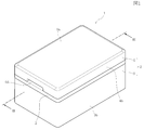
- FIG. 1 The perspective view which shows the external appearance of the sounding device manufactured with the manufacturing method of embodiment of this invention, 1 is an exploded perspective view of the sound producing device shown in FIG.
- FIG. 3 is a cross-sectional view of the sounding device shown in FIG. Sectional drawing which shows the assembly operation of the sounding device shown in FIG.
- frame and vibrating body of embodiment of this invention The disassembled perspective view which shows the assembly state of the flame
- an explanatory view showing the process of bonding the vibration support sheet to the frame by process In the production method of the sound producing device of the embodiment of the present invention, an explanatory view showing the process of bonding the diaphragm to the vibration support sheet and simultaneously forming the flexure part by process,
- the sound generation device 1 has a case 2.
- the case 2 includes a lower case 3 and an upper case 4.
- the lower case 3 and the upper case 4 are made of a synthetic resin, a nonmagnetic material, or a magnetic metal material by a die casting method. Alternatively, it is formed by pressing using a nonmagnetic or magnetic metal plate.
- the lower case 3 is a first case
- the upper case 4 is a second case.
- the lower case 3 has a bottom 3a, a side wall 3b surrounding the four side surfaces, and an open end 3c at the upper end of the side wall 3b.
- the upper case 4 has a ceiling part 4a, a side wall part 4b surrounding the four side surfaces, and an open end part 4c at the lower end of the side wall part.
- the internal space of the lower case 3 is wider than the internal space of the upper case 4, and the upper case 4 functions as a lid for the lower case.
- a sandwiched portion 6 around the frame 5 is sandwiched between the opening end 3 c of the lower case 3 and the opening end 4 c of the upper case 4.
- the sandwiched portion 6 sandwiched between the lower case 3 and the upper case 4 the lower case 3, the upper case 4, and the sandwiched portion 6 are fixed to each other by laser spot welding.
- the frame 5 is formed in a frame shape from a non-magnetic material or a metal plate made of a magnetic material having a uniform thickness dimension in the Z direction.
- the lower plane in the figure is a drive side mounting surface 5a
- the upper plane is a vibrating body mounting surface 5b.
- an opening 5 c is formed in the center of the frame 5 so as to penetrate vertically.
- the opening 5c is a rectangular hole.
- the vibrating body mounting surface 5b is formed so as to surround the periphery of the opening 5c.
- the frame 5 having this structure is manufactured by pressing a metal plate having a uniform thickness.
- the opening 5c is formed by punching a metal plate material.
- the entire periphery of the vibration body mounting surface 5b is protruded downward in the Z direction, thereby forming a sandwiched portion 6 that is lowered by a step portion 7 around the vibration body mounting surface 5b. Is done.
- the sandwiched portion 6 can be formed, and by further performing the protrusion process, the rigidity of the frame 5 can be increased.
- the sounding device 1 is provided with a vibrating body 10.
- the vibrating body 10 includes a diaphragm 11 and a vibration support sheet 12.
- the diaphragm 11 is made of a thin metal material such as aluminum or SUS304. As shown in FIG. 8, the area of the diaphragm 11 is smaller than the opening area of the opening 5 c of the frame 5.
- the diaphragm 11 has a rectangular shape, both edges 11a and 11a extending in the Y direction (vertical direction) are formed on both sides in the X direction (width direction), and one edge in the Y direction is a free end 11b. The other edge is a fulcrum end 11c.
- the diaphragm 11 is press-molded with ribs 11d for increasing the bending strength.
- the plurality of ribs 11d are formed in parallel in a straight line in the Y direction with an interval in the X direction. As shown in the sectional view of FIG. 6, the rib 11 d is formed in a protruding shape toward the internal space of the upper case 4.
- the vibration support sheet 12 is more easily bent and deformed than the vibration plate 11, and is, for example, a resin sheet (resin film) such as PET (polyethylene terephthalate), nylon, or polyurethane.
- resin film such as PET (polyethylene terephthalate), nylon, or polyurethane.
- the vibration plate 11 is bonded and fixed to the lower surface of the vibration support sheet 12, and the vibration member mounting surface in which the peripheral portion 12 a of the vibration support sheet 12 is the upper surface of the frame portion of the frame 5. It is fixed to 5b via an adhesive. As a result, the vibration plate 11 is supported by the frame 5 through the vibration support sheet 12 so as to freely vibrate. As shown in FIGS. 3, 4, and 6, the diaphragm 11 is located inside the opening 5 c of the frame 5 and is located within the range of the thickness dimension of the frame 5.
- a gap (i) is formed between both edge portions 11 a and 11 a in the X direction (width direction) of the diaphragm 11 and the inner edge portion of the opening 5 c of the frame 5.
- a gap (ii) is formed between the free end 11 b of the diaphragm 11 and the inner edge of the opening 5 c of the frame 5.
- a gap (iii) narrower than the gap (ii) is formed between the fulcrum side end 11c of the diaphragm 11 and the inner edge of the opening 5c of the frame 5, or almost no gap is formed.
- the gaps (i) (ii) (iii) between the four sides of the diaphragm 11 and the inner edge of the opening 5 c are closed by the vibration support sheet 12.
- a bending portion 12b is formed in the vibration support sheet 12.
- the bending portion 12b is obtained by heating and deforming a resin sheet (resin film) constituting the vibration support sheet 12.
- the bending portion 12b functions as a bending deformation portion or a bending bulging portion.
- the length of the portion that appears in the cross section of the resin sheet that becomes the bending portion 12b is equal to the cross section.
- the diaphragm 11 can vibrate so that the free end portion 11b is displaced in the Z direction with the fulcrum side end portion 11c as a fulcrum.
- the deformation portion deformed on the vibration support sheet 12 so as to follow the rib 11 d of the vibration plate 11. 12c is formed.
- the rib 11d of the vibration plate 11 and the bent portion 12b and the deformed portion 12c of the vibration support sheet 12 protrude in a projecting manner toward the internal space of the upper case 4.
- the deformed portion 12c of the vibration support sheet 12 protrude in a projecting manner toward the internal space of the upper case 4.
- or all of them may protrude in a protruding shape toward the internal space of the lower case 3.
- the magnetic field generation unit 20 is attached to the drive side attachment surface 5 a of the frame 5.
- the magnetic field generation unit 20 has an upper yoke 21 and a lower yoke 22.
- the upper yoke 21 and the lower yoke 22 are made of a magnetic material, and are made of, for example, a steel plate such as a cold rolled steel plate represented by SPCC, a Ni—Fe alloy, or the like.
- the lower yoke 22 is bent in a U shape, and a bottom surface portion 22a and a pair of side surface portions 22b and 22b bent upward on both sides in the X direction are integrally formed. .
- the upper end portions of the side surface portions 22b and 22b are joined to the inner surface 21a of the flat plate-shaped upper yoke 21, and the upper yoke 21 and the lower yoke 22 are fixed by laser spot welding or the like.
- the inner surface of the bottom surface portion 22a of the lower yoke 22 and the inner surface 21a of the upper yoke 21 face each other in parallel.
- the width dimension of the upper yoke 21 is formed such that both end portions in the X direction protrude to both sides from the side outer surfaces of the side surface portions 22b and 22b of the lower yoke 22.
- the upper magnet 24 is fixed to the inner surface 21a of the upper yoke 21
- the lower magnet 25 is fixed to the inner surface of the bottom surface portion 22a of the lower yoke 22.
- a gap ⁇ in the Z direction is formed between the lower surface 24 a of the upper magnet 24 and the upper surface 25 a of the lower magnet 25.
- the magnets 24 and 25 are magnetized so that the lower surface 24a of the upper magnet 24 and the upper surface 25a of the lower magnet 25 have opposite polarities.
- a coil 27 is provided at a position aligned with the magnetic field generation unit 20.
- the coil 27 is wound so that the conducting wire circulates around a winding axis extending in the Y direction.
- the movable portion 32a of the armature 32 is inserted into the space 27c of the winding center portion of the coil 27, and the conducting wire of the coil 27 is wound around the movable portion 32a of the armature 32. .
- the end surface of the coil 27 facing the left side in the Y direction is a bonding surface 27 a, and this bonding surface 27 a extends in the Y direction of the upper yoke 21 and the lower yoke 22 of the magnetic field generation unit 20. It is fixed on the facing side with adhesive. At this time, the winding center line of the coil 27 is positioned and fixed to each other so as to coincide with the center of the gap ⁇ between the upper magnet 24 and the lower magnet 25.
- the sounding device 1 is provided with an armature 32.
- the armature 32 is formed of a magnetic material plate having a uniform thickness, and is formed of, for example, a Ni—Fe alloy.
- the armature 32 is pressed and bent into a U shape having a movable portion 32a, a fixed portion 32b, and a bent portion 32c.
- the movable portion 32a and the fixed portion 32b face each other in parallel with a gap in the Z direction.
- the tip 32d facing the Y direction of the movable portion 32a of the armature 32 has a small width dimension in the X direction, and a connecting hole 32e is formed through the tip 32d so as to penetrate vertically. .
- the fixing portion 32 b of the armature 32 is fixed to a joint surface 21 b that is an upward outer surface of the upper yoke 21.
- the movable portion 32 a of the armature 32 is inserted into the space 27 c of the coil 27 and further inserted into the gap ⁇ between the upper magnet 24 and the lower magnet 25.
- the tip 32d of the armature 32 protrudes forward in the Y direction from the gap ⁇ .
- the joint surface 21 b on the upper surface of the upper yoke 21 is a flat surface, and the joint surface 21 b is joined and fixed to the drive side mounting surface 5 a on the lower surface of the frame 5.
- the upper yoke 21 is installed so as to cross the opening 5 c of the frame 5 in the X direction, and both ends in the X direction of the upper yoke 21 are joined to the drive side mounting surface 5 a of the frame 5. Then, the upper yoke 21 and the frame 5 are fixed by laser spot welding or the like.
- the fixing portion 32 b of the armature 32 is smaller than the opening area of the opening 5 c of the frame 5, and the drive side mounting surface 5 a in which the joint surface 21 b on the upper surface of the upper yoke 21 is the lower surface of the frame 5.
- the fixing portion 32b of the armature 32 fixed to the joint surface 21b enters the inside of the opening 5c of the frame 5.
- the thickness dimension in the Z direction of the fixed portion 32 b is smaller than the thickness dimension in the Z direction of the frame 5. Therefore, a gap in the Z direction is provided between the diaphragm 11 that is also located in the opening 5c and the fixed portion 32b of the armature 32 so that the diaphragm 11 can vibrate in the Z direction.
- the transmission body 33 is a needle-like member made of metal or synthetic resin, and is made of, for example, a pin material of SUS202.
- the upper end 33a of the transmission body 33 is inserted into a mounting hole 11e formed in the diaphragm 11, and the diaphragm 11 and the transmission body 33 are fixed by an adhesive or soldering.
- the vibration support sheet 12 is formed with a clearance hole 12 d so as to avoid a joint portion between the vibration plate 11 and the transmission body 33.
- the lower end portion 33b of the transmission body 33 is inserted into a connecting hole 32e formed in the tip portion 32d of the armature 32, and the transmission body 33 and the tip portion 32d are fixed by laser welding, adhesive, or soldering.
- the transmission body 33 traverses the opening 5c of the frame 5 up and down, and a part of the transmission body 33 is located inside the opening 5c.
- the magnetic field generating unit 20 the coil 27, the armature 32, and the transmission body 33 constitute a drive mechanism for vibrating the vibrating body 10.
- the outer peripheral portion of the frame 5 is sandwiched and fixed between the opening end 3 c of the lower case 3 and the opening end 4 c of the upper case 4.
- the peripheral portion 12a and the adhesive layer of the vibration support sheet 12 joined to the vibration body mounting surface 5b of the frame 5 are spaced inward from the inner surface of the case 2, and the peripheral portion 12a is an opening of the lower case 3. It is not sandwiched between the end 3c and the open end 4c of the upper case 4. Since the vibration support sheet 12 and the adhesive are not sandwiched between the lower case 3 and the upper case 4, the cases 3 and 4 can be firmly fixed to each other. Further, when the lower case 3 and the upper case 4 are fixed by laser welding or the like, the vibration support sheet 12 can be prevented from being damaged or deformed by heat.
- the space inside the case 2 is formed by the vibrating body 10 including the vibration plate 11 and the vibration support sheet 12. Divided vertically.
- a space above the vibrating body 10 and inside the upper case 4 is a sound generation side space, and the sound generation side space communicates with an external space from a sound generation port 4d formed in the side wall portion 4b of the upper case 4.
- a sound generation nozzle 41 communicating with the sound generation port 4 d is fixed to the outside of the case 2.
- an intake / exhaust port 3d is formed at the bottom of the lower case 3, and the inner space of the lower case 3 below the vibrating body 10 is formed by the intake / exhaust port 3d. Open air.
- a pair of wiring holes 3 e are opened in the side wall portion 3 b of the lower case 3, and as shown in FIG. 3, the pair of terminal portions 27 b of the conductive wires constituting the coil 27 are respectively connected to the wiring holes. It is pulled out from 3e.
- the substrate 42 is fixed to the outside of the side wall portion 3b of the case, and the terminal portion 27b passes through a small hole formed in the substrate 42 so that the small hole is closed, whereby the wiring hole 3e is closed from the outside.
- the assembly operation (manufacturing method) of the sound generating device 1 is as follows. As shown in FIG. 4, the sound producing device 1 has components incorporated with a frame 5 as a reference.
- FIG. 9 shows a process of bonding the vibration support sheet 12 to the frame 5.
- the first jig 50 is used.
- the first jig 50 has a frame installation surface 51 and a center fitting protrusion 52.
- the center fitting protrusion 52 has a quadrangular cross section so that it can be fitted into the opening 5c of the frame 5 with almost no gap.
- the frame installation surface 51 is formed so as to be on the same plane all around the center fitting protrusion 52.
- the frame 5 is set on the first jig 50.
- the opening 5 c of the frame 5 is fitted into the center fitting protrusion 52, and the lower surface of the sandwiched portion 6 of the frame 5 is installed so as to abut against the frame installation surface 51.
- the surface 52 a of the center fitting protrusion 52 is the same surface as the vibration body mounting surface 5 b that is the upper surface of the frame 5 or toward the frame installation surface 51. It is preferable that it be a little lower.
- an adhesive is applied to the vibration body mounting surface 5b which is the upper surface of the frame 5.
- the adhesive can be applied in the range of the width dimension W from the inner edge of the opening 5c to the stepped portion 7 on the vibration body mounting surface 5b. It is possible to prevent the adhesive from protruding to the sandwiched portion 6. Therefore, when the sandwiched portion 6 is sandwiched between the lower case 3 and the upper case 4 and laser spot welding is performed, the adhesive is sandwiched between the sandwiched portion 6 and the open end 4 c of the upper case 4. It becomes easy to prevent.
- a resin sheet to be the vibration support sheet 12 is bonded to the region of the width dimension W of the vibration member mounting surface 5b of the frame 5.
- bonding is performed while applying a uniform tension T to the resin sheet.
- the acting direction of the tension T is at least the X direction, and is preferably given uniformly in the X direction and the Y direction.
- the adhesive is, for example, UV curable. Until the adhesive is cured, the center fitting protrusion 52 of the first jig 50 is fitted into the opening 5c of the frame 5. Therefore, the reaction of the tension T can prevent the frame 5 from being distorted or the frame 5 from being deformed so that the width of the opening 5c is narrowed.
- the frame 5 is detached from the first jig 50 as shown in FIG.
- FIG. 10 shows a process of bonding the diaphragm 11 to the vibration support sheet 12.
- the second jig 60 shown in FIG. 10A is used.
- the second jig 60 includes a vibration plate installation portion 61 that is a positioning portion of the vibration plate 11, and a bending forming portion 62 that surrounds the entire circumference of the vibration plate installation portion 61.
- the width dimension W ⁇ b> 0 in the X direction and the width dimension in the Y direction of the diaphragm installation portion 61 substantially coincide with the width dimensions of the planar shape of the diaphragm 11.
- a frame mounting surface 63 is formed on the outer periphery of the bending forming portion 62.
- the frame mounting surface 63 is flush with the entire peripheral length of the bending portion 62.
- the diaphragm 11 is installed and positioned on the diaphragm installation portion 61 of the second jig 60.
- An adhesive is previously applied to the upward surface of the diaphragm 11 in the figure.
- the adhesive is applied to the entire upper surface of the diaphragm 11 or is applied intermittently.
- the frame 5 is mounted toward the frame mounting surface 63.
- the distance between the outer side surfaces 62 a of the bending forming portion 62 of the second jig 60 matches the designed opening width dimension of the opening portion 5 c of the frame 5. Therefore, an appropriate tension is applied to the vibration support sheet 12 bonded to the frame 5 by fitting the opening 5 c into the outer side surface 62 a of the bending molding portion 62.
- the pressure P can be set, for example, by performing so-called pressure forming that increases the air pressure in the environment where the second jig 60 exists. Alternatively, it is set by pressing a pressure member in which air is sealed inside the elastic body against the second jig 60. Alternatively, it is set by pressing an elastic body such as silicon rubber against the second jig 60.
- the vibration support sheet 12 is heated by setting the second jig 60 or by increasing the environmental temperature.
- the lower surface of the clamping portion 6 around the frame 5 is pressed against the frame mounting surface 63 by the pressure P.
- the vibration supporting sheet 12 positioned between the inner edge of the opening 5c of the frame 5 and the diaphragm 11 is partially deformed by the bending forming portion 62, and the bending portion 12b is formed. Furthermore, at the same time, a deformed portion 12 c is formed on the vibration support sheet 12 so as to follow the rib 11 d of the vibration plate 11.
- the vibration support sheet 12 on the outer peripheral side of the adhesive region having the width W shown in FIGS. 9 (B) and 9 (C) is trimmed, and as shown in FIG. The frame 5 is detached from the second jig 60.
- a uniform tension T is applied to the vibration support sheet 12, and in the process of FIG. 10D, each part is uniform from the surface of the vibration support sheet 12 toward the second jig 60.
- the bent portion 12b can be formed so as to have a uniform raised height with a uniform width in various places.
- the step of bonding the vibration support sheet 12 and the vibration plate 11 and the step of forming the bending portion 12b on the vibration support sheet 12 can be performed simultaneously.
- the diaphragm setting portion 61 for positioning the diaphragm 11 and the bending molding section 62 are formed on the second jig 60, the relative position between the frame 5 and the diaphragm 11 can be set with high accuracy.
- the relative position between the diaphragm 11 and the bent portion 12b can also be determined with high accuracy.
- the upper magnet 24 is joined to the inner surface 21a of the upper yoke 21, the lower magnet 25 is joined to the upper surface of the bottom surface portion 22a of the lower yoke 22, and the upper yoke 21 and the lower yoke 22 are connected to the racer.
- the magnetic field generating unit 20 is assembled by fixing by spot welding or the like.
- the joint surface 27a of the coil 27 is fixed to the side surfaces of the upper yoke 21 and the lower yoke 22 facing the Y direction with an adhesive.
- the center in the Z direction of the gap ⁇ between the upper magnet 24 and the lower magnet 25 is made to coincide with the center in the Z direction of the space 27c of the coil 27 using a positioning jig.
- the armature 32 is formed by press working, and the bent portion 32c is processed so that the movable portion 32a and the fixed portion 32b can face each other in parallel or almost in parallel in the Z direction.
- the movable portion 32a of the armature 32 is inserted into the center of the coil 27 and the center of the gap ⁇ between the magnets 24 and 25, and the fixed portion 32b is directly abutted against the joining surface 21b which is the upper surface of the upper yoke 21 to perform laser. Fix by spot welding.
- the coil 27, and the armature 32 are assembled on the drive side mounting surface 5a, the tip 32d of the movable portion 32a of the armature 32 and the diaphragm 11 are connected by the transmission body 33 to assemble the drive mechanism. To complete.
- the peripheral edge of the frame 5 is sandwiched between the open end 3c of the lower case 3 and the open end 4c of the upper case 4, and the lower case 3, the frame 5 and the upper case 4 are fixed by laser spot welding. To do. Further, the terminal portion 27 b of the conducting wire of the coil 27 is drawn out from the wiring hole 3 e of the lower case 3 and the wiring hole 3 e is covered with the substrate 42. Further, the sound generating nozzle 41 is fixed to the case 2 to complete the assembly.
- the operation of the sound generator 1 will be described.
- a voice current is applied to the coil 27, a magnetic field is induced in the armature 32. Due to the magnetic field induced in the armature 32 and the magnetic field generated in the gap ⁇ between the upper magnet 24 and the lower magnet 25, vibration in the Z direction is generated in the movable portion 32a of the armature 32. This vibration is transmitted to the diaphragm 11 via the transmission body 33.
- the diaphragm 11 supported by the vibration support sheet 12 vibrates with the free end portion 11b swinging in the Z direction with the fulcrum end portion 11c as a fulcrum. Due to the vibration of the diaphragm 11, sound pressure is generated in the sound generation space inside the upper case 4, and this sound pressure is output from the sound output 4 d to the outside.
- the bending portion 12 b is uniformly formed on the vibration support sheet 12 by the gap (i) (ii) between the inner edge portion of the opening 5 c of the frame 5 and the diaphragm 11. It can be formed with a uniform width and a uniform raised height, and the relative position between the diaphragm 11 and the bent portion 12b can be determined with high accuracy. Therefore, the vibration characteristic of the diaphragm 11 is good, and variation in sound generation characteristics can be suppressed.
Landscapes
- Engineering & Computer Science (AREA)
- Physics & Mathematics (AREA)
- Acoustics & Sound (AREA)
- Signal Processing (AREA)
- Manufacturing & Machinery (AREA)
- Electromagnetism (AREA)
- Electrostatic, Electromagnetic, Magneto- Strictive, And Variable-Resistance Transducers (AREA)
- Audible-Bandwidth Dynamoelectric Transducers Other Than Pickups (AREA)
- Diaphragms For Electromechanical Transducers (AREA)
Abstract
【課題】 振動板とフレームと振動支持シートを高精度に位置決めして接着でき、振動板とフレームとの間の撓み部も均一に成形できる発音装置の製造方法を提供する。 【解決手段】 フレーム5に振動支持シート12を、均一に張力を与えて接着する。第2の治具60の振動体設置部61に振動板11を位置決めして設置し、フレーム5をフレーム装着面63に向けて装着する。振動支持シート12を加熱しながら均一な圧力Pを与えると、振動板11が振動支持シート12に接着され、第2の治具60の撓み成形部62によって撓み部12bが形成される。
Description
本発明は、振動板と振動支持シートから成る振動体がフレームに接着されて支持されており、前記振動体を駆動する駆動機構が設けられている発音装置の製造方法に関する。
特許文献1に、電気音響変換器に関する発明が記載されている。
この電気音響変換器は、ダイヤフラムの上面に接着された樹脂フィルムの周囲部分が枠状のダイヤフラムフレームの上面に接着剤を介して固定されている。前記ダイヤフラムフレームは、2つのハウジングの開口端部に挟まれて、ダイヤフラムフレームとハウジングとがレーザー溶接で固定されている。ハウジング内には、アーマチュア部が設けられている。アーマチュア部は、磁石およびコイルと、前記コイルに与えられる電流で振動させられるアーマチュアとを有しており、前記アーマチュアの振動によって前記ダイヤフラム駆動される。
この電気音響変換器は、ダイヤフラムの上面に接着された樹脂フィルムの周囲部分が枠状のダイヤフラムフレームの上面に接着剤を介して固定されている。前記ダイヤフラムフレームは、2つのハウジングの開口端部に挟まれて、ダイヤフラムフレームとハウジングとがレーザー溶接で固定されている。ハウジング内には、アーマチュア部が設けられている。アーマチュア部は、磁石およびコイルと、前記コイルに与えられる電流で振動させられるアーマチュアとを有しており、前記アーマチュアの振動によって前記ダイヤフラム駆動される。
この電気音響変換器のダイヤフラムと樹脂フィルムの組み付け方法は、図16に示されているように、ダイヤフラムフレームとダイヤフラムの上面に接着剤を塗布した後に、樹脂フィルムを加熱して圧着し、ダイヤフラムフレームとダイヤフラムを樹脂フィルムに接着して固定する。その後、CO2レーザーを用い、ダイヤフラムフレームの形状に沿って樹脂フィルムを切断する。このとき、ダイヤフラムフレーム上に接着剤と樹脂フィルムとが除去された除去部が形成される。この除去部において、ダイヤフラムフレームとハウジングとをレーザー溶接で固定することで、ダイヤフラムフレームとハウジングとの間に接着剤と樹脂フィルムとが挟まれて溶接されるのを防止し、溶接部に隙間が形成されるなどの現象を抑制しようというものである。
特許文献1に記載された発明では、ダイヤフラムフレームとダイヤフラムを樹脂フィルムに接着する際に、樹脂フィルムに張力を与える工程を備えていない。そのため、ダイヤフラムフレームとダイヤフラムの上面に樹脂フィルムを接着する際に、ダイヤフラムフレームとダイヤフラムとの間に位置している樹脂フィルムの張力が不均一になりやすく、ダイヤフラムフレーム内でのダイヤフラムの振動を均一化できず、製品によって振動特性にばらつきが発生する原因になる。
また、特許文献1に記載された電気音響変換器では、図14と図15に示すように、ダイヤフラムフレームとダイヤフラムとの間において、樹脂フィルムを凸または凹の円弧状部に形成することで、ダイヤフラムの振動時の振幅を確保できるようにしている。しかし、前述のようにダイヤフラムフレームとダイヤフラムとの間で樹脂フィルムの張力にばらつきがあると、前記凸または凹の円弧状部の成形精度が悪くなり、円弧状部の深さや幅寸法が場所によってばらつくようになり、これによってもダイヤフラムの振動特性にばたつきが生じやすくなる。
さらに、特許文献1には、前記凸または凹の円弧状部をどのようにして、精度良く成形するかについて、なんら示されていない。
本発明は上記従来の課題を解決するものであり、フレームの開口部内に、振動支持シートを均一な張力で設置して、フレームと振動板との間において、振動支持シートに撓み部を均一に形成できるようにした発音装置の製造方法を提供することを目的としている。
本発明は、フレームと、前記フレームに取付けられた振動体と、前記振動体を駆動する駆動機構とが設けられた発音装置の製造方法について、
前記フレームは、開口部と、前記開口部の周囲の振動体取付け面とを有し、前記振動体は、振動板と、前記振動板を前記フレームに支持させる振動支持シートとを有しており、(1)前記振動支持シートに張力を与えて、その周囲部分を、前記フレームの前記振動体取付け面に接着する工程と、
(2)前記フレームの前記開口部の範囲内で、前記振動体を前記振動支持シートに接着する工程と、
(3)前記(2)の工程と同時にまたはその後に、前記フレームと前記振動体との間において、前記振動支持シートに撓み部を形成する工程と、
を有することを特徴とするものである。
前記フレームは、開口部と、前記開口部の周囲の振動体取付け面とを有し、前記振動体は、振動板と、前記振動板を前記フレームに支持させる振動支持シートとを有しており、(1)前記振動支持シートに張力を与えて、その周囲部分を、前記フレームの前記振動体取付け面に接着する工程と、
(2)前記フレームの前記開口部の範囲内で、前記振動体を前記振動支持シートに接着する工程と、
(3)前記(2)の工程と同時にまたはその後に、前記フレームと前記振動体との間において、前記振動支持シートに撓み部を形成する工程と、
を有することを特徴とするものである。
本発明の発音装置の製造方法は、前記(1)の工程では、前記フレームの前記開口部内に第1の治具を挿入した状態で、張力を与えた前記振動支持シートを前記振動体取付け面に接着することが好ましい。
本発明の発音装置の製造方法は、前記振動板の設置部と、前記撓みを成形する撓み成形部とが設けられた第2の治具を使用し、
前記(2)の工程で、前記振動板を前記設置部に設置して位置決めし、前記フレームを前記第2の治具に設置して、前記フレームに貼られている前記振動支持シートと前記振動板とを接着し、
前記(3)の工程で、前記振動支持シートを前記撓み成形部に加圧して、前記撓み部を成形するものである。
前記(2)の工程で、前記振動板を前記設置部に設置して位置決めし、前記フレームを前記第2の治具に設置して、前記フレームに貼られている前記振動支持シートと前記振動板とを接着し、
前記(3)の工程で、前記振動支持シートを前記撓み成形部に加圧して、前記撓み部を成形するものである。
本発明の発音装置の製造方法では、前記振動板にリブが一体に形成されており、前記(2)の工程で、前記振動体支持シートを前記振動板に加圧し、前記振動体支持シートを前記リブの形状に倣うように接着することが可能である。
本発明の発音装置の製造方法は、前記(2)と(3)の工程を同時に行うことが好ましい。
この場合に、本発明の発音装置の製造方法は、前記振動体支持シートを、均一な圧力で前記振動板および前記撓み成形部に加圧することが好ましい。
本発明の発音装置の製造方法は、前記(3)の工程では、前記振動体支持シートを加熱することが好ましい。
本発明の発音装置の製造方法は、振動支持シートを、張力を与えてフレームに接着することで、振動支持シートで振動板を安定して支持することができる。また、フレームと振動板の間に形成される振動支持シートの撓み部を、均一に成形することができ、振動板の振動特性を安定させることができる。
また、フレームの開口部内に第1の治具を装着した状態で、振動支持シートに張力を与えてフレームに接着することで、振動支持シートの張力で、フレームが歪んだり、開口部が狭められた状態で接着が行われるのを防止でき、振動支持シートをフレームの開口部内に均一な張力で貼り付けることができる。
また、第2の治具に振動板の設置部と、撓み部を形成する撓み成形部を設け、第2の治具に振動板を位置決めして、振動支持シートを押し付けることで、振動板と撓み部の相対位置を高精度に決めて、振動体を製造することが可能になる。
図1ないし図4に本発明の実施の形態の発音装置1が示されている。
発音装置1は、ケース2を有している。図1と図2に示すように、ケース2は下ケース3と上ケース4とから構成されている。下ケース3と上ケース4は合成樹脂製または非磁性材料または磁性の金属材料を使用しダイキャスト法で形成されている。あるいは、非磁性または磁性金属板を使用してプレス加工で形成されている。下ケース3が第1のケースであり、上ケース4が第2のケースである。
発音装置1は、ケース2を有している。図1と図2に示すように、ケース2は下ケース3と上ケース4とから構成されている。下ケース3と上ケース4は合成樹脂製または非磁性材料または磁性の金属材料を使用しダイキャスト法で形成されている。あるいは、非磁性または磁性金属板を使用してプレス加工で形成されている。下ケース3が第1のケースであり、上ケース4が第2のケースである。
図2に示すように、下ケース3は、底部3aと、4側面を囲む側壁部3bと、側壁部3bの上端の開口端部3cを有している。上ケース4は天井部4aと、4側面を囲む側壁部4bと、側壁部の下端の開口端部4cを有している。下ケース3の内部空間は、上ケース4の内部空間よりも広く、上ケース4は下ケースの蓋体として機能している。
図3と図6に示すように、下ケース3の開口端部3cと上ケース4の開口端部4cとの間にフレーム5の周囲の被挟持部6が挟まれている。下ケース3と上ケース4との間に被挟持部6が挟まれた状態で、下ケース3と上ケース4と被挟持部6とがレーザースポット溶接によって互いに固定されている。
図2に示すように、フレーム5は、Z方向の厚さ寸法が均一な非磁性材料のあるいは磁性材料製の金属板材で枠形状に形成されている。フレーム5は、図示下側の平面が駆動側取付け面5aで、上側の平面が振動体取付け面5bとなっている。図5にも示すように、フレーム5の中央部に、開口部5cが上下に貫通して形成されている。開口部5cは矩形状の穴である。前記振動体取付け面5bは、開口部5cの周囲を囲むように形成されている。
この構造のフレーム5は、厚さ寸法が均一な金属板材をプレス加工することで製造される。開口部5cは、金属板材を打ち抜くことで形成される。また、振動体取付け面5bの周囲の全体を、Z方向の下向きに突き出し加工することで、振動体取付け面5bの周囲に、段差部7を介して、一段低くなった被挟持部6が形成される。この突き出し加工を行うことで、被挟持部6を形成することができ、さらに突き出し加工を行うことで、フレーム5の剛性を高めることもできる。
図2に示すように、発音装置1には振動体10が設けられている。振動体10は振動板11と振動支持シート12とで構成されている。
振動板11はアルミニウムやSUS304などの薄い金属材料で形成されている。図8に示すように、振動板11の面積は、フレーム5の開口部5cの開口面積よりも小さい。振動板11は矩形状であり、X方向(幅方向)の両側にY方向(縦方向)に延びる両縁部11a,11aが形成され、Y方向の一方の縁部が自由端部11bで、他方の縁部が支点側端部11cとなっている。振動板11には曲げ強度を増強するためのリブ11dがプレス成形されている。複数のリブ11dは、X方向に間隔を空けてY方向に直線状に平行に形成されている。図6の断面図に示すように、リブ11dは上ケース4の内部空間に向けて突状に形成されている。
振動支持シート12は振動板11よりも撓み変形しやすいものであり、例えばPET(ポリエチレンテレフタレート)やナイロンあるいはポリウレタンなどの樹脂シート(樹脂フィルム)である。
図6と図7に示すように、振動板11は振動支持シート12の下面に接着されて固定され、振動支持シート12の周囲部分12aが、フレーム5の枠部の上面である振動体取付け面5bに接着剤を介して固定されている。その結果、振動板11は、振動支持シート12を介してフレーム5に振動自在に支持されている。また、図3と図4および図6に示すように、振動板11は、フレーム5の開口部5cの内部に位置し、フレーム5の厚さ寸法の範囲内に位置している。
図5と図6および図8に示すように、振動板11の面積は、フレーム5の開口部5cの開口面積よりも小さいが、振動支持シート12の面積は振動板11よりも大きい。そのため、振動板11のX方向(幅方向)の両縁部11a,11aとフレーム5の開口部5cの内縁部との間に隙間(i)が形成されている。図3と図4と図5および図8に示すように、振動板11の自由端部11bとフレーム5の開口部5cの内縁部との間に隙間(ii)が形成されている。振動板11の支点側端部11cとフレーム5の開口部5cの内縁部との間には、前記隙間(ii)よりも狭い隙間(iii)が形成され、あるいはほとんど隙間が形成されていない。
図5と図8に示すように、振動板11の4辺と開口部5cの内縁部との間の各隙間(i)(ii)(iii)は振動支持シート12で塞がれている。隙間(i)(ii)に対応する部分では、振動支持シート12に撓み部12bが形成されている。撓み部12bは、振動支持シート12を構成している樹脂シート(樹脂フィルム)を加熱して変形させたものである。撓み部12bは、撓み用変形部あるいは撓み用隆起部として機能するものであり、図3と図6において、撓み部12bとなる樹脂シートの断面に現れている部分の述べ長さが、前記断面での前記隙間(i)(ii)の幅よりも長くなっている。この撓み部12bの存在により、振動板11は、支点側端部11cを支点として、自由端部11bがZ方向へ変位するように振動可能となっている。
図6と図7および図8に示すように、振動板11の上に振動支持シート12が接着される際に、振動支持シート12に、振動板11のリブ11dに倣うように変形した変形部12cが形成される。特に、振動板11と振動支持シート12とを接着するときに振動支持シート12を加熱することで、変形部12cをリブ11dに完全に倣う形状に成形しやすくなる。なお、実施の形態では、振動板11のリブ11dおよび振動支持シート12の撓み部12bと変形部12cが、上ケース4の内部空間に向けて突状に隆起しているが、これらのいずれかが、または全てが、下ケース3の内部空間に向けて突状に隆起していてもよい。
図3と図4および図6に示すように、フレーム5の駆動側取付け面5aに磁界発生ユニット20が取り付けられている。図2に示すように、磁界発生ユニット20は、上部ヨーク21と下部ヨーク22とを有している。上部ヨーク21と下部ヨーク22は、磁性材料で形成されており、例えばSPCCに代表される冷間圧延鋼板などの鋼板やNi-Fe合金などで形成されている。
図2に示すように、下部ヨーク22はU字形状に曲げられており、底面部22aと、X方向の両側で上向きに折り曲げられた一対の側面部22b,22bとが一体に形成されている。側面部22b,22bの上端部が、平板形状の上部ヨーク21の内面21aに接合され、レーザースポット溶接などで、上部ヨーク21と下部ヨーク22とが固定されている。上部ヨーク21と下部ヨーク22とが固定されると、下部ヨーク22の底面部22aの内面と、上部ヨーク21の内面21aとが平行に対向する。上部ヨーク21の幅寸法は、X方向の両端部が、下部ヨーク22の側面部22b,22bの側外面よりも両側へ突出するように形成されている。
図2ないし図4に示すように、磁界発生ユニット20では、上部ヨーク21の内面21aに上部磁石24が固定され、下部ヨーク22の底面部22aの内面に下部磁石25が固定されている。図3と図6に示すように、上部磁石24の下面24aと下部磁石25の上面25aとの間にZ方向のギャップδが形成されている。上部磁石24の下面24aと下部磁石25の上面25aは、互いに逆の極性となるように、各磁石24,25が着磁されている。
図2と図3に示すように、磁界発生ユニット20と並ぶ位置にコイル27が設けられている。コイル27はY方向に延びる巻き軸を中心として導線が周回するように巻かれている。後に説明するように、コイル27の巻き中心部の空間27cにアーマチュア32の可動部32aが挿入されるが、コイル27の導線はアーマチュア32の可動部32aの周囲を周回するように巻かれている。
図3と図4に示すように、コイル27のY方向の左側に向く端面が接合面27aとなっており、この接合面27aが磁界発生ユニット20の上部ヨーク21と下部ヨーク22のY方向に向く側面に接着剤などで固定されている。このとき、コイル27の巻き中心線が、上部磁石24と下部磁石25とのギャップδの中心に一致するように位置決めされて互いに固定される。
図2と図3および図4に示すように、発音装置1にアーマチュア32が設けられている。アーマチュア32は厚さが均一な磁性材料の板材で形成されており、例えば、Ni-Fe合金で形成されている。アーマチュア32はプレス加工され、可動部32aと固定部32bと曲げ部32cを有するU字形状に曲げ加工されている。可動部32aと固定部32bは、Z方向に間隔を空けて互いに平行に対向している。図2に示すように、アーマチュア32の可動部32aのY方向に向く先部32dはX方向の幅寸法が小さくなっており、先部32dに連結穴32eが上下に貫通して形成されている。
図3と図4および図5に示すように、アーマチュア32の固定部32bは、上部ヨーク21の上向きの外面である接合面21bに固定されている。また、アーマチュア32の可動部32aは、コイル27の空間27cの内部に挿入され、さらに上部磁石24と下部磁石25との間のギャップδ内に挿入されている。そして、アーマチュア32の先部32dは、前記ギャップδ内からY方向の前方に飛び出している。
図3と図4に示すように、上部ヨーク21の上面の接合面21bは平面であり、この接合面21bがフレーム5の下面の駆動側取付け面5aに接合されて固定されている。図6に示すように、上部ヨーク21は、フレーム5の開口部5cをX方向へ横断するように設置され、上部ヨーク21のX方向の両端部が、フレーム5の駆動側取付け面5aに接合されて、上部ヨーク21とフレーム5とがレーザースポット溶接などで固定される。
図5に示すように、アーマチュア32の固定部32bは、フレーム5の開口部5cの開口面積よりも小さく、上部ヨーク21の上面の接合面21bが、フレーム5の下面である駆動側取付け面5aに直接に固定されると、図3と図6に示すように、前記接合面21bに固定されているアーマチュア32の固定部32bが、フレーム5の開口部5cの内部に入り込む。固定部32bのZ方向の厚さ寸法は、フレーム5のZ方向の厚さ寸法よりも小さい。よって、同じく開口部5c内に位置する振動板11と、アーマチュア32の固定部32bとの間には、振動板11がZ方向に振動できるようにZ方向の隙間が空けられる。
図3に示すように、振動板11の自由端部11bと、アーマチュア32の先部32dとが、伝達体33で連結されている。伝達体33は金属または合成樹脂で形成された針状部材であり、例えばSUS202のピン材で形成されている。伝達体33の上端33aは振動板11に形成された取付け穴11eに挿入されて、振動板11と伝達体33とが接着剤または半田付けで固定されている。図7と図8に示すように、振動支持シート12には、振動板11と伝達体33との接合部を避けるように逃げ穴12dが形成されている。伝達体33の下端部33bは、アーマチュア32の先部32dに形成された連結穴32eに挿入されて、伝達体33と先部32dとがレーザー溶接あるいは接着剤または半田付けで固定されている。伝達体33はフレーム5の開口部5c内を上下に横断しており、伝達体33の一部が開口部5cの内部に位置している。
発音装置1では、磁界発生ユニット20とコイル27とアーマチュア32および伝達体33とで、振動体10を振動させるための駆動機構が構成されている。
図3と図6に示すように、フレーム5の外周部分は、下ケース3の開口端部3cと上ケース4の開口端部4cとの間に挟まれて固定されている。ただし、フレーム5の振動体取付け面5bに接合されている振動支持シート12の周囲部分12aおよび接着剤層は、ケース2の内面から内側に離れており、周囲部分12aは、下ケース3の開口端部3cと上ケース4の開口端部4cとの間に挟まれていない。下ケース3と上ケース4との間に振動支持シート12および接着剤が挟まれないので、ケース3,4を互いに強固に固定できる。また下ケース3と上ケース4をレーザー溶接などで固定するときに、振動支持シート12が熱で損傷し、あるいは変形するのを防止することができる。
下ケース3と上ケース4との間にフレーム5の被挟持部6が挟まれて固定されると、振動板11と振動支持シート12とからなる振動体10によって、ケース2の内部の空間が上下に区分される。振動体10よりも上側であって上ケース4の内部の空間が発音側空間であり、発音側空間は、上ケース4の側壁部4bに形成された発音口4dから外部空間に通じている。図3に示すように、ケース2の外側には、前記発音口4dに通じる発音ノズル41が固定されている。
図2と図3に示すように、下ケース3の底部には吸排気口3dが形成されており、振動体10よりも下側であって下ケース3の内部空間が、吸排気口3dによって外気に通じている。図2に示すように、下ケース3の側壁部3bには一対の配線穴3eが開口しており、図3に示すように、コイル27を構成する導線の一対の端末部27bがそれぞれ配線穴3eから外部に引き出されている。ケースの側壁部3bの外部には基板42が固定され、端末部27bが基板42に形成された小穴内を通過しこの小穴が塞がれることで、配線穴3eが外側から閉鎖されている。
発音装置1の組立作業(製造方法)は以下の通りである。
図4に示すように、この発音装置1は、フレーム5を基準として各部品が組み込まれている。
図4に示すように、この発音装置1は、フレーム5を基準として各部品が組み込まれている。
図9に、フレーム5に振動支持シート12を接着する工程が示されている。この工程には第1の治具50が使用される。図9(A)に示すように、第1の治具50は、フレーム設置面51と、中央嵌合突部52とを有している。中央嵌合突部52は、フレーム5の開口部5cにほぼ隙間なく嵌めこむことができるよう断面が四角形状に形成されている。フレーム設置面51は、中央嵌合突部52の周囲全周において同一平面となるように形成されている。
図9(B)に示すように、フレーム5を第1の治具50に設置する。このとき、フレーム5の開口部5cを中央嵌合突部52に嵌入し、フレーム5の被挟持部6の下面を、フレーム設置面51に突き当てるように設置する。第1の治具50にフレーム50が設置された状態で、中央嵌合突部52の表面52aが、フレーム5の上面である振動体取付け面5bと同一面か、あるいはフレーム設置面51側へ少し低くなっていることが好ましい。
図9(B)において、第1の治具50にフレーム5を設置した後に、フレーム5の上面である振動体取付け面5bに接着剤を塗布する。フレーム5の周囲に突き出し加工で段差部7を形成することで、接着剤は、振動体取付け面5bにおいて、開口部5cの内縁部から段差部7までの幅寸法Wの範囲に塗布することができ、接着剤が被挟持部6まではみ出すのを防止できるようになる。よって、被挟持部6が下ケース3と上ケース4とで挟まれてレーザースポット溶接されるときに、接着剤が、被挟持部6と上ケース4の開口端4cとの間に挟まれるのを防止しやすくなる。
図9(C)では、フレーム5の振動体取付け面5bの幅寸法Wの領域に振動支持シート12となる樹脂シートを接着する。このとき、樹脂シートに均一な張力Tを与えながら接着する。張力Tの作用方向は少なくともX方向であり、好ましくは、X方向とY方向に均一に与えられる。接着剤は例えばUV硬化性である。接着剤が硬化するまでの間、フレーム5の開口部5cに第1の治具50の中央嵌合突部52が嵌合している。そのため、前記張力Tの反作用により、フレーム5が歪んだり、あるいはフレーム5が開口部5cの幅寸法が狭まるように変形するのを防止できるようになる。接着が完了した後に、図9(D)に示すように、フレーム5を第1の治具50から離脱させる。
図10に、振動支持シート12に振動板11を接着する工程が示されている。この工程では、図10(A)に示す第2の治具60が使用される。第2の治具60は、振動板11の位置決め部である振動板設置部61と、振動板設置部61の全周を囲む撓み成形部62を有している。振動板設置部61のX方向の幅寸法W0とY方向の幅寸法は、振動板11の平面形状のそれぞれの幅寸法とほぼ一致している。第2の治具60では、撓み成形部62の外周にフレーム装着面63が形成されている。フレーム装着面63は撓み成形部62の周囲全長において同一平面である。
図10(B)の工程では、第2の治具60の振動板設置部61に振動板11を設置して位置決めする。振動板11の図示上向きの面には予め接着剤を塗布しておく。接着剤は振動板11の上面の全面に塗布し、または間欠的に塗布する。次に、図10(C)に示すように、フレーム5をフレーム装着面63に向けて装着する。第2の治具60の撓み成形部62の外側面62aの間隔は、フレーム5の開口部5cの設計上の開口幅寸法と一致している。そのため、開口部5cを撓み成形部62の外側面62aに嵌め込むことで、フレーム5に接着されている振動支持シート12に適正な張力が与えられる。
図10(D)の工程で、振動支持シート12を加熱しながら、振動支持シート12に対して第2の治具60に向かう均一な圧力Pを与える。この圧力Pは、例えば第2の治具60が存在する環境での空気圧を上昇させる、いわゆる圧空成形を行うことで設定できる。または、弾性体の内部に空気を封入した加圧部材を第2の治具60に押し付けることで設定される。あるいはシリコンゴムなどの弾性体を第2の治具60に押し付けることにより設定される。振動支持シート12の加熱は、第2の治具60を加熱することで設定され、または環境温度を高めることで行われる。
図10(D)の工程では、圧力Pによって、フレーム5の周囲の挟持部6の下面がフレーム装着面63に押し付けられる。同時に、撓み成形部62によって、フレーム5の開口部5cの内縁部と振動板11との間に位置する振動支持シート12が部分的に変形させられて撓み部12bが成形される。さらに、同時に、振動支持シート12に、振動板11のリブ11dに倣うように変形部12cが形成される。図10(D)の工程の後で、図9(B)(C)に示す幅寸法Wの接着領域よりも外周側の振動支持シート12をトリミングし、図10(E)に示すように、フレーム5を第2の治具60から離脱させる。
図9に示した接着工程で、振動支持シート12に均一な張力Tを与え、図10(D)の工程で、振動支持シート12の表面から第2の治具60に向けて各部分で均一な圧力Pを与えることで、図7に示すように、撓み部12bを各所において均一な幅で均一な隆起高さとなるように成形することができる。また、振動支持シート12と振動板11とを接着する工程と、振動支持シート12に撓み部12bを成形する工程とを同時に行うことが可能になる。さらに、第2の治具60に、振動板11を位置決めする振動板設置部61と撓み成形部62とが形成されているため、フレーム5と振動板11との相対位置を高精度に設定でき、振動板11と撓み部12bとの相対位置も高精度に決めることができる。
さらに発音装置1の製造方法では、上部ヨーク21の内面21aに上部磁石24を接合し、下部ヨーク22の底面部22aの上面に下部磁石25を接合し、上部ヨーク21と下部ヨーク22とをレーサースポット溶接などで固定して、磁界発生ユニット20を組み立てる。また、コイル27の接合面27aを上部ヨーク21と下部ヨーク22のY方向に向く側面に接着剤で固定する。このとき、位置決め治具を用いて、上部磁石24と下部磁石25とのギャップδのZ方向での中心と、コイル27の空間27cのZ方向の中心を一致させる。
アーマチュア32は、プレス加工で形成し、可動部32aと固定部32bとがZ方向で平行にまたはほぼ平行に対向できるように曲げ部32cを加工する。アーマチュア32の可動部32aを、コイル27の中心と、磁石24,25間のギャップδの中心に挿入し、固定部32bを、上部ヨーク21の上面である接合面21bに直接に突き当ててレーザースポット溶接などで固定する。
次に、ヨーク21,22と磁石24,25とから成る磁界発生ユニット20にコイル27とアーマチュア32が組み込まれた部分組立体を、フレーム5の駆動側取付け面5aに固定する。上部ヨーク21の接合面21bをフレーム5の駆動側取付け面5aに突き当て、レーザースポット溶接などで固定する。
駆動側取付け面5aに磁界発生ユニット20とコイル27およびアーマチュア32を組み込んだ後に、アーマチュア32の可動部32aの先部32dと振動板11との間を伝達体33で連結し、駆動機構の組立を完了する。
その後、下ケース3の開口端部3cと上ケース4の開口端部4cとの間に、フレーム5の周縁部を挟むようにし、下ケース3とフレーム5と上ケース4をレーザースポット溶接で固定する。また、コイル27の導線の端末部27bは下ケース3の配線穴3eから外部に引出し、配線穴3eを基板42で覆う。さらにケース2に発音ノズル41を固定して組立を完了する。
次に、発音装置1の動作を説明する。
発音装置1の動作は、ボイス電流がコイル27に与えられると、アーマチュア32に磁界が誘導される。アーマチュア32に誘導される磁界と、上部磁石24と下部磁石25とのギャップδ内に生成される磁界とで、アーマチュア32の可動部32aにZ方向への振動が発生する。この振動が伝達体33を介して振動板11に伝達される。このとき、振動支持シート12で支持されている振動板11は、支点側端部11cを支点として自由端部11bがZ方向へ振れて振動する。振動板11の振動により、上ケース4の内部の発音空間に音圧が生成され、この音圧が発音口4dから外部へ出力される。
発音装置1の動作は、ボイス電流がコイル27に与えられると、アーマチュア32に磁界が誘導される。アーマチュア32に誘導される磁界と、上部磁石24と下部磁石25とのギャップδ内に生成される磁界とで、アーマチュア32の可動部32aにZ方向への振動が発生する。この振動が伝達体33を介して振動板11に伝達される。このとき、振動支持シート12で支持されている振動板11は、支点側端部11cを支点として自由端部11bがZ方向へ振れて振動する。振動板11の振動により、上ケース4の内部の発音空間に音圧が生成され、この音圧が発音口4dから外部へ出力される。
この発音装置1では、図9と図10の組立工程において、フレーム5の開口部5cの内縁部と振動板11との隙間(i)(ii)で、振動支持シート12に撓み部12bを均一な幅で均一な隆起高さで成形でき、さらに、振動板11と撓み部12bとの相対位置も高精度に決めることができる。そのため、振動板11の振動特性が良好であり、発音特性のばらつきを抑制することが可能である。
1 発音装置
2 ケース
3 下ケース
4 上ケース
5 フレーム
5b 振動体取付け面
5c 開口部
6 被挟持部
10 振動体
11 振動板
11a 縁部
11b 自由端
11c 支点側端部
11d リブ
12 振動支持シート
12a 周囲部分
12b 撓み部
12c 変形部
21 上部ヨーク
22 下部ヨーク
24 第1の磁石
25 第2の磁石
32 アーマチュア
50 第1の治具
60 第2の治具
2 ケース
3 下ケース
4 上ケース
5 フレーム
5b 振動体取付け面
5c 開口部
6 被挟持部
10 振動体
11 振動板
11a 縁部
11b 自由端
11c 支点側端部
11d リブ
12 振動支持シート
12a 周囲部分
12b 撓み部
12c 変形部
21 上部ヨーク
22 下部ヨーク
24 第1の磁石
25 第2の磁石
32 アーマチュア
50 第1の治具
60 第2の治具
Claims (7)
- フレームと、前記フレームに取付けられた振動体と、前記振動体を駆動する駆動機構とが設けられた発音装置の製造方法について、
前記フレームは、開口部と、前記開口部の周囲の振動体取付け面とを有し、前記振動体は、振動板と、前記振動板を前記フレームに支持させる振動支持シートとを有しており、(1)前記振動支持シートに張力を与えて、その周囲部分を、前記フレームの前記振動体取付け面に接着する工程と、
(2)前記フレームの前記開口部の範囲内で、前記振動体を前記振動支持シートに接着する工程と、
(3)前記(2)の工程と同時にまたはその後に、前記フレームと前記振動体との間において、前記振動支持シートに撓み部を形成する工程と、
を有することを特徴とする発音装置の製造方法。 - 前記(1)の工程では、前記フレームの前記開口部内に第1の治具を挿入した状態で、張力を与えた前記振動支持シートを前記振動体取付け面に接着する請求項1記載の発音装置の製造方法。
- 前記振動板の設置部と、前記撓みを成形する撓み成形部とが設けられた第2の治具を使用し、
前記(2)の工程で、前記振動板を前記設置部に設置して位置決めし、前記フレームを前記第2の治具に設置して、前記フレームに貼られている前記振動支持シートと前記振動板とを接着し、
前記(3)の工程で、前記振動支持シートを前記撓み成形部に加圧して、前記撓み部を成形する請求項1または2記載の発音装置の製造方法。 - 前記振動板にリブが一体に形成されており、前記(2)の工程で、前記振動体支持シートを前記振動板に加圧し、前記振動体支持シートを前記リブの形状に倣うように接着する請求項3記載の発音装置の製造方法。
- 前記(2)と(3)の工程を同時に行う請求項3または4記載の発音装置の製造方法。
- 前記振動体支持シートを、均一な圧力で前記振動板および前記撓み成形部に加圧する請求項5記載の発音装置の製造方法。
- 前記(3)の工程で、前記振動体支持シートを加熱する請求項3ないし6のいずれかに記載の発音装置の製造方法。
Priority Applications (2)
| Application Number | Priority Date | Filing Date | Title |
|---|---|---|---|
| JP2018522319A JP6618619B2 (ja) | 2016-06-09 | 2017-02-27 | 発音装置の製造方法 |
| CN201780032404.0A CN109314831A (zh) | 2016-06-09 | 2017-02-27 | 发音装置的制造方法 |
Applications Claiming Priority (2)
| Application Number | Priority Date | Filing Date | Title |
|---|---|---|---|
| JP2016-115471 | 2016-06-09 | ||
| JP2016115471 | 2016-06-09 |
Publications (1)
| Publication Number | Publication Date |
|---|---|
| WO2017212697A1 true WO2017212697A1 (ja) | 2017-12-14 |
Family
ID=60578550
Family Applications (1)
| Application Number | Title | Priority Date | Filing Date |
|---|---|---|---|
| PCT/JP2017/007335 Ceased WO2017212697A1 (ja) | 2016-06-09 | 2017-02-27 | 発音装置の製造方法 |
Country Status (3)
| Country | Link |
|---|---|
| JP (1) | JP6618619B2 (ja) |
| CN (1) | CN109314831A (ja) |
| WO (1) | WO2017212697A1 (ja) |
Citations (2)
| Publication number | Priority date | Publication date | Assignee | Title |
|---|---|---|---|---|
| JP2002027598A (ja) * | 2000-07-12 | 2002-01-25 | Star Micronics Co Ltd | 電気音響変換器及びその製造方法 |
| JP2012004851A (ja) * | 2010-06-17 | 2012-01-05 | Sony Corp | 音響変換装置及び音響変換装置の組立方法 |
Family Cites Families (2)
| Publication number | Priority date | Publication date | Assignee | Title |
|---|---|---|---|---|
| CN100377622C (zh) * | 2004-02-11 | 2008-03-26 | 瑞声声学科技(深圳)有限公司 | 背极驻极体电容式传声器制造方法 |
| CN101102622B (zh) * | 2006-07-07 | 2011-12-14 | 欧力天工股份有限公司 | 振动膜组装体的制造方法以及电容式传声器 |
-
2017
- 2017-02-27 CN CN201780032404.0A patent/CN109314831A/zh active Pending
- 2017-02-27 WO PCT/JP2017/007335 patent/WO2017212697A1/ja not_active Ceased
- 2017-02-27 JP JP2018522319A patent/JP6618619B2/ja not_active Expired - Fee Related
Patent Citations (2)
| Publication number | Priority date | Publication date | Assignee | Title |
|---|---|---|---|---|
| JP2002027598A (ja) * | 2000-07-12 | 2002-01-25 | Star Micronics Co Ltd | 電気音響変換器及びその製造方法 |
| JP2012004851A (ja) * | 2010-06-17 | 2012-01-05 | Sony Corp | 音響変換装置及び音響変換装置の組立方法 |
Also Published As
| Publication number | Publication date |
|---|---|
| JP6618619B2 (ja) | 2019-12-11 |
| CN109314831A (zh) | 2019-02-05 |
| JPWO2017212697A1 (ja) | 2019-03-14 |
Similar Documents
| Publication | Publication Date | Title |
|---|---|---|
| EP0650308B1 (en) | Electroacoustic transducer and method of fabricating the same | |
| US20180184210A1 (en) | Sound generation device and production method therefor | |
| JP6014787B1 (ja) | 発音装置 | |
| JP6618619B2 (ja) | 発音装置の製造方法 | |
| CN108028994B (zh) | 发声装置 | |
| JP6629460B2 (ja) | 発音装置およびその製造方法 | |
| US10735863B2 (en) | Sound producing device | |
| JP2001245390A (ja) | 電気音響変換器 | |
| JP2019092113A (ja) | 発音装置 | |
| JP6438867B2 (ja) | 発音装置 | |
| WO2017212696A1 (ja) | 発音装置 | |
| WO2017212698A1 (ja) | 発音装置 | |
| WO2018034015A1 (ja) | 発音装置およびその製造方法 | |
| WO2019098181A1 (ja) | 発音装置 | |
| JP6697145B2 (ja) | 発音装置 | |
| WO2017195433A1 (ja) | 発音装置 | |
| JPH09215091A (ja) | 電磁型発音体 | |
| JP2017059988A (ja) | 発音装置 | |
| JP2002186091A (ja) | マイクロスピーカ | |
| JP2002149162A (ja) | 電磁音響変換器 | |
| WO2019049846A1 (ja) | 発音装置 | |
| CN111327996A (zh) | 声学振膜、声学振膜的制造方法以及电声换能器 | |
| HK1011138B (en) | Electroacoustic transducer and method of fabricating the same | |
| JP2017059987A (ja) | 発音装置 |
Legal Events
| Date | Code | Title | Description |
|---|---|---|---|
| ENP | Entry into the national phase |
Ref document number: 2018522319 Country of ref document: JP Kind code of ref document: A |
|
| 121 | Ep: the epo has been informed by wipo that ep was designated in this application |
Ref document number: 17809881 Country of ref document: EP Kind code of ref document: A1 |
|
| NENP | Non-entry into the national phase |
Ref country code: DE |
|
| 122 | Ep: pct application non-entry in european phase |
Ref document number: 17809881 Country of ref document: EP Kind code of ref document: A1 |