WO2017208960A1 - 車載投影装置 - Google Patents
車載投影装置 Download PDFInfo
- Publication number
- WO2017208960A1 WO2017208960A1 PCT/JP2017/019520 JP2017019520W WO2017208960A1 WO 2017208960 A1 WO2017208960 A1 WO 2017208960A1 JP 2017019520 W JP2017019520 W JP 2017019520W WO 2017208960 A1 WO2017208960 A1 WO 2017208960A1
- Authority
- WO
- WIPO (PCT)
- Prior art keywords
- display
- pair
- reflection
- housing
- unit
- Prior art date
- Legal status (The legal status is an assumption and is not a legal conclusion. Google has not performed a legal analysis and makes no representation as to the accuracy of the status listed.)
- Ceased
Links
Images

Classifications
-
- B—PERFORMING OPERATIONS; TRANSPORTING
- B60—VEHICLES IN GENERAL
- B60K—ARRANGEMENT OR MOUNTING OF PROPULSION UNITS OR OF TRANSMISSIONS IN VEHICLES; ARRANGEMENT OR MOUNTING OF PLURAL DIVERSE PRIME-MOVERS IN VEHICLES; AUXILIARY DRIVES FOR VEHICLES; INSTRUMENTATION OR DASHBOARDS FOR VEHICLES; ARRANGEMENTS IN CONNECTION WITH COOLING, AIR INTAKE, GAS EXHAUST OR FUEL SUPPLY OF PROPULSION UNITS IN VEHICLES
- B60K35/00—Instruments specially adapted for vehicles; Arrangement of instruments in or on vehicles
- B60K35/20—Output arrangements, i.e. from vehicle to user, associated with vehicle functions or specially adapted therefor
- B60K35/21—Output arrangements, i.e. from vehicle to user, associated with vehicle functions or specially adapted therefor using visual output, e.g. blinking lights or matrix displays
- B60K35/23—Head-up displays [HUD]
-
- B—PERFORMING OPERATIONS; TRANSPORTING
- B60—VEHICLES IN GENERAL
- B60K—ARRANGEMENT OR MOUNTING OF PROPULSION UNITS OR OF TRANSMISSIONS IN VEHICLES; ARRANGEMENT OR MOUNTING OF PLURAL DIVERSE PRIME-MOVERS IN VEHICLES; AUXILIARY DRIVES FOR VEHICLES; INSTRUMENTATION OR DASHBOARDS FOR VEHICLES; ARRANGEMENTS IN CONNECTION WITH COOLING, AIR INTAKE, GAS EXHAUST OR FUEL SUPPLY OF PROPULSION UNITS IN VEHICLES
- B60K35/00—Instruments specially adapted for vehicles; Arrangement of instruments in or on vehicles
- B60K35/20—Output arrangements, i.e. from vehicle to user, associated with vehicle functions or specially adapted therefor
- B60K35/21—Output arrangements, i.e. from vehicle to user, associated with vehicle functions or specially adapted therefor using visual output, e.g. blinking lights or matrix displays
- B60K35/22—Display screens
-
- B—PERFORMING OPERATIONS; TRANSPORTING
- B60—VEHICLES IN GENERAL
- B60K—ARRANGEMENT OR MOUNTING OF PROPULSION UNITS OR OF TRANSMISSIONS IN VEHICLES; ARRANGEMENT OR MOUNTING OF PLURAL DIVERSE PRIME-MOVERS IN VEHICLES; AUXILIARY DRIVES FOR VEHICLES; INSTRUMENTATION OR DASHBOARDS FOR VEHICLES; ARRANGEMENTS IN CONNECTION WITH COOLING, AIR INTAKE, GAS EXHAUST OR FUEL SUPPLY OF PROPULSION UNITS IN VEHICLES
- B60K35/00—Instruments specially adapted for vehicles; Arrangement of instruments in or on vehicles
- B60K35/50—Instruments characterised by their means of attachment to or integration in the vehicle
-
- G—PHYSICS
- G02—OPTICS
- G02B—OPTICAL ELEMENTS, SYSTEMS OR APPARATUS
- G02B27/00—Optical systems or apparatus not provided for by any of the groups G02B1/00 - G02B26/00, G02B30/00
- G02B27/01—Head-up displays
-
- G—PHYSICS
- G09—EDUCATION; CRYPTOGRAPHY; DISPLAY; ADVERTISING; SEALS
- G09F—DISPLAYING; ADVERTISING; SIGNS; LABELS OR NAME-PLATES; SEALS
- G09F9/00—Indicating arrangements for variable information in which the information is built-up on a support by selection or combination of individual elements
-
- B—PERFORMING OPERATIONS; TRANSPORTING
- B60—VEHICLES IN GENERAL
- B60K—ARRANGEMENT OR MOUNTING OF PROPULSION UNITS OR OF TRANSMISSIONS IN VEHICLES; ARRANGEMENT OR MOUNTING OF PLURAL DIVERSE PRIME-MOVERS IN VEHICLES; AUXILIARY DRIVES FOR VEHICLES; INSTRUMENTATION OR DASHBOARDS FOR VEHICLES; ARRANGEMENTS IN CONNECTION WITH COOLING, AIR INTAKE, GAS EXHAUST OR FUEL SUPPLY OF PROPULSION UNITS IN VEHICLES
- B60K35/00—Instruments specially adapted for vehicles; Arrangement of instruments in or on vehicles
- B60K35/60—Instruments characterised by their location or relative disposition in or on vehicles
Definitions
- the present invention relates to an in-vehicle projection apparatus that is mounted on a vehicle and includes a reflecting member for projecting a display image.
- This in-vehicle projection device is a head-up display device in which a reflection unit (reflection means) having a reflection unit including a display unit (display means) having a light source or a liquid crystal panel and a mirror in a housing (housing) in which an emission part is formed. ), And the display light (display image) of the display unit is reflected through the reflection unit, and is projected onto the predetermined irradiation member and the windshield of the automobile through the emission unit to perform projection display.
- the reflection unit is provided through a holder so as to be rotatable about a predetermined rotation axis so that the position of the display image irradiated on the windshield as an irradiation member can be moved and adjusted.
- the holder is provided with a pair of shaft portions (rotary shafts) that project to the periphery along the rotation axis, while the housing side is provided with a pair of bearing portions that support the pair of shaft portions, By holding these shaft portions by bearings at the bearing portions, the reflection unit held through the holder is configured to be rotatable.
- on-vehicle projection devices may require a large display screen, and the reflection unit tends to be enlarged accordingly.
- the reflection unit When the reflection unit is enlarged, the frictional resistance between the shaft portion and the bearing portion of the reflection unit is increased, which causes a problem that smooth rotation cannot be obtained.
- the in-vehicle projection device is desired to smoothly rotate the reflecting portion without generating an abnormal sound even when there is a vibration or thermal effect associated with traveling.
- the reflection portion also vibrates due to the vibration caused by the traveling of the vehicle, but if this vibration is transmitted to the drive means for adjusting the position of the reflection portion, there is a possibility that abnormal noise is generated or smooth rotation cannot be performed. .
- an object of the present invention is to provide an in-vehicle projection device that is pivotally supported so that the reflecting portion can be rotated more smoothly, paying attention to the above-described problems.
- the in-vehicle projector of the present invention is In the case where the emission part is formed, Display means for outputting display light; Reflecting means for providing a reflecting portion for reflecting the display light to the emitting portion side and a pair of rotating shafts protruding to both end sides of the reflecting portion; Driving means for adjusting a reflection angle by the reflecting portion by rotating the rotation shaft on one side of the pair of rotation shafts; A rolling bearing having an inner ring through which the rotating shaft is inserted and an outer ring held on the housing side on both sides of the pair of rotating shafts; With A plurality of the rolling bearings are provided on a side of the pair of rotating shafts where the driving unit is provided.
- the drive means is provided outside the rolling bearing.
- the present invention is an in-vehicle projection device that is pivotally supported so that the reflecting portion can rotate more smoothly.
- FIG. 1 is a schematic view of a head-up display device according to an embodiment of the present invention.
- a head-up display device (vehicle-mounted projection device) A is mounted on, for example, an automobile, and includes a housing (housing) 1, a display unit (display means) 2, and a backlight unit 3.
- the plane mirror 4 is generated through the display unit 2 and the backlight unit 3, and is reflected through the plane mirror 4 and the reflection unit 5.
- the display is performed by irradiating the windshield (windshield) 7 of the vehicle with display light (display image) L, and examples of display contents include various vehicle information and navigation (route guidance) information.
- the housing 1 is made of, for example, black synthetic resin.
- the housing 1 houses the display unit 2, the backlight unit 3, the plane mirror 4, the reflection unit 5, and the actuator 6, and displays light on the side facing the windshield 7.
- An emission part 8 for emitting L toward the windshield 7 is formed, and the emission part 8 is covered with a translucent cover 9.
- the housing space for each component can be formed by combining locations made of a metal material such as aluminum in consideration of thermal deformation and heat dissipation as the housing. Further, a housing enclosed by each unit may be combined to form a housing.
- the display unit 2 includes a display element made of, for example, a liquid crystal display panel that receives the light from the backlight unit 3 and forms a display image (display light) L, and is fixedly disposed on the housing 1.
- a display element made of, for example, a liquid crystal display panel that receives the light from the backlight unit 3 and forms a display image (display light) L, and is fixedly disposed on the housing 1.
- the backlight unit 3 includes a light source substrate, a light source, a lens member, a case, and the like, and is fixed to the housing 1 by being positioned behind the display unit 2.
- the plane mirror 4 reflects the display light L from the display unit 2 toward the reflection unit 5.
- the reflection unit 5 is configured to reflect the display light (display image) L incident through the plane mirror 4 toward the emission unit 8 and to be rotatable about a rotation axis to be described later with the operation of the actuator 6.
- the display light L reflected through the reflection unit 5 passes through the translucent cover 9 provided in the emission part 8 and is irradiated onto the windshield 7 to be visually recognized by the occupant P as a virtual image.
- the actuator 6 is composed of, for example, a stepping motor, and is attached and fixed to the housing 1 in a state of being connected to the rotation shaft 521 of the reflection unit 5 through a plurality of gears.
- the reflection unit 5 includes a reflection part 51, a holder 52, and a support part 53.
- the reflecting portion 51 is made of, for example, a concave mirror in which a reflecting film is formed on the surface of a base material made of a synthetic resin material by means such as vapor deposition.
- the reflection surface of the reflection part 51 has a curved surface corresponding to the shape of the windshield 7 and also has an effect of correcting the distortion of the virtual image seen from the passenger P.
- the holder 52 is made of, for example, a black metal material, and a mounting table 522 on which the rotating shaft 521 and the reflecting portion 51 projecting from both ends are formed.
- the reflecting portion 51 is fixed to the mounting table 522 with a double-sided tape or the like.
- a ball bearing (rolling bearing) 54 that is inserted and supported by the rotating shaft 521, and a bearing holding portion 55 that holds the ball bearing 54 at a predetermined position of the housing 1. Yes.
- the support portion 53 includes a ball bearing 54 and a bearing holding portion 55, which are assembled in advance, inserted through the rotary shaft 521, and further held by the housing 1.
- the support portion 53 can pivotally support the reflecting portion 51 relative to the housing 1. In this case, three similar support parts 53 are prepared.
- the ball bearing 54 is interposed between the outer ring 541 having a cylindrical shape, an inner ring 542 provided inside the outer ring 541 and having a hole through which the rotation shaft 521 is inserted, and the outer ring 541 and the inner ring 542 to smoothly rotate.
- the bearing holding portion 55 is configured to hold the hole 551 in which the outer ring 541 of the ball bearing 54 is fitted and fit, a wall portion 552 that defines an assembly position of the outer ring 541, and a bolt 56 at a predetermined position of the housing 1. And a hole portion 553.
- the bearing holding portion 55 can hold the ball bearing 54 by being press-fitted into the hole 551.
- the ball bearing 54 is inserted by pressing the outer ring 541 from the opening side of the hole 551 by a press-fitting jig (not shown) to a position where it comes into contact with the wall portion 552.
- the press fitting jig and the wall portion 552 are applied with a shape and an assembling method so as to hit the outer ring 541 and do not hit the inner ring 542, and a pressure force is applied to the inner ring 542 so that the ball 543 is detached or damaged. 54 troubles are prevented.
- the bearing holding portion 55 that holds and holds the ball bearing 54 is press-fitted while the inner ring 542 of the ball bearing 54 is inserted into the rotating shaft 521 so that the inner ring 542 and the flange portion 521a of the ball bearing 54 are sandwiched by using a press-fitting jig. And assembled.
- the wall portion 552 extends so as to narrow the gap between the window portion 554 and the flange portion 521a. Even if a problem occurs in the cover 544, the wall portion 552 and the flange portion 521a. Therefore, the lubricant 545 can be prevented from scattering toward the reflecting portion 51 side. Moreover, the structure of the wall part 552 and the flange part 521a becomes a structure which prevents that the lubricant 545 is scattered to the reflective part 51 side also in the air blow process after the assembly.
- a similar bearing holding portion 55 that stores and holds the ball bearing 54 is provided by being inserted into the rotating shafts 521 on both sides of the reflecting portion 51, and another rotating shaft 521 on the actuator 6 side is provided with another bearing holding portion.
- a portion 55 is provided. Accordingly, a plurality of bearing holding portions 55 are provided between the actuator 6 and the reflection portion 51, and it is difficult to transmit vibrations at the reflection portion 51 (between the ball bearings 54 on both sides of the reflection portion 51) to the actuator 6 side. is doing.
- the actuator 6 includes a motor 61 and a plurality of gears 62, and the rotation of the motor 61 is transmitted to the rotating shaft 521 via the gear 62.
- One of the gears 62 is provided to be fitted to the end side (outside) of the plurality of bearing holding portions 55 on the rotation shaft 521, and rotates together with the rotation shaft 521. Further, another gear 62 is prepared so that the rotation of the motor 61 is transmitted to the gear 62 at a reduced speed.
- the distance between the shaft supports by the ball bearings 54 at both ends is increased with the increase in the size of the reflecting portion 51, and the mounting table 522 is easily bent due to resonance with the vibration of the vehicle.
- the plurality of ball bearings 54 between the actuator 6 and the reflecting portion 51 it is possible to suppress the deformation of the rotating shaft 521 and to suppress the vibration from being transmitted to the gear 62 side. As a result, for example, it is possible to prevent problems such as hitting of gears and generating a hitting sound. Further, since the driving force of the motor 61 can be properly transmitted to the rotating shaft 521 even during traveling, the reflecting portion 51 can be smoothly rotated.
- Such a head-up display device A includes: In the housing (housing) 1 in which the translucent cover (light emitting part) 9 is formed, A display unit (display means) 2 for outputting display light L; A reflecting unit (reflecting means) 5 that includes a reflecting portion 51 that reflects the display light L toward the translucent cover 9 and a pair of rotating shafts 521 that protrude to both ends of the reflecting portion 51; An actuator (driving means) 6 that adjusts the reflection angle by the reflecting portion 51 by rotating the rotation shaft 521 on one side of the pair of rotation shafts 521; A ball bearing (rolling bearing) 54 having an inner ring 542 through which the rotating shaft 521 is inserted and an outer ring 541 held on the housing 1 side on both sides of the pair of rotating shafts 521; A plurality of ball bearings 54 are provided on the side of the pair of rotating shafts 521 where the actuator 6 is provided.
- the actuator 6 is provided outside the ball bearing 54 and is supported by a rotating shaft near the reflecting portion 51 and the mounting table 522, so that the distance between the shafts can be made as small as possible and the amount of deflection (amplitude) can be minimized. . Therefore, vibrations such as resonance can be suppressed.
- the head-up display device A of the present invention has been described by way of example in the configuration of the above-described embodiment, but the present invention is not limited to this, and the gist of the present invention is also in other configurations. It goes without saying that various improvements and display changes can be made without departing from the scope of the invention.
- an example using a liquid crystal panel that forms a display image using the irradiation light of the backlight unit 3 has been described as an example.
- laser light is scanned as illumination light.
- the projector system using DMD digital mirror device
- DMD digital mirror device
- the present invention relates to a head-up display device, for example, suitable as an in-vehicle display device for vehicle information and road information such as turn-by-turn display mounted on a moving body including an automobile, a motorcycle, or an agricultural machine or a construction machine. is there.
- a Head-up display device on-vehicle projection device
- Housing housing
- Display unit display means
- Backlight unit Flat mirror
- Reflection unit reflection means
- Holder Rotating shaft
- Supporting portion 54
- Ball bearing (rolling bearing) 541
- Outer ring 542
- Inner ring 543
- Ball 544 Cover 545
- Lubricant 55
- Bearing holding portion 551
- Hole 552 Wall portion 553
- Hole portion 554 Window portion 6
- Windshield Emission part
- Translucent cover emission part
Landscapes
- Engineering & Computer Science (AREA)
- Chemical & Material Sciences (AREA)
- Combustion & Propulsion (AREA)
- Transportation (AREA)
- Mechanical Engineering (AREA)
- Physics & Mathematics (AREA)
- General Physics & Mathematics (AREA)
- Optics & Photonics (AREA)
- Theoretical Computer Science (AREA)
- Instrument Panels (AREA)
Abstract
反射ユニットがより滑らかに回動できるように軸支したヘッドアップディスプレイ装置を提供する。 透光性カバー9が形成されたハウジング1に、表示光Lを出力する表示ユニット2と、表示光Lを透光性カバー9側へ反射する反射部51と反射部51の両端側に突出する一対の回転軸521とを設ける反射ユニット5と、前記一対の回転軸521の一方側に、回転軸521を回転させることによって反射部51による反射角度を調整するアクチュエータ6と、前記一対の回転軸521の両側に、回転軸521が挿通される内輪542とハウジング1側に保持される外輪541とを有するボールベアリング54と、を備え、前記一対の回転軸521のうちアクチュエータ6が設けられる側には、複数のボールベアリング54が設けられる。
Description
本発明は、車両に搭載され、表示像を投影するための反射部材を備えた車載投影装置に関する。
従来の車載投影装置として、例えば特許文献1に記載のものが知られている。この車載投影装置は、ヘッドアップディスプレイ装置として、出射部が形成されたハウジング(筐体)に例えば光源や液晶パネルを有する表示ユニット(表示手段)とミラーからなる反射部を有する反射ユニット(反射手段)を収容し、表示ユニットの表示光(表示像)を反射ユニットを通じて反射させると共に出射部を通じて所定の照射部材、自動車のウインドシールドに照射して投影表示を行う。
反射ユニットは、ホルダを通じて保持され、照射部材たるウインドシールドに照射される表示像の位置を移動させて位置調整を行えるよう、所定の回転軸線を中心として回動可能に設けられている。この際、ホルダには、回転軸線に沿って周囲に突出する一対の軸部(回転軸)が設けられ、一方、ハウジング側にはこれら一対の軸部を支持する一対の軸受け部が設けられ、これら軸部を軸受け部で軸受け保持することでホルダを通じて保持した反射ユニットを回動可能に構成している。
これら車載投影装置は、大きな表示画面が求められることもあり、これにともなって反射ユニットも大型化してしまう傾向にある。反射ユニットが大型化する場合、上記反射ユニットの軸部と軸受け部との摩擦抵抗も大きくなるため、スムーズな回動が得られないという問題があった。特に、車載投影装置は、走行に伴う振動や熱影響があっても、異音を発生せずに滑らかに反射部を回動させることが望まれている。
例えば、車両の走行にともなう振動によって、反射部も振動するが、この振動が反射部の位置調整用の駆動手段に伝わると、異音の発生や、滑らかな回動ができないという虞があった。
そこで本発明の目的は、上述した課題に着目し、反射部がより滑らかに回動できるように軸支した車載投影装置を提供することにある。
本発明の車載投影装置は、
出射部が形成された筐体に、
表示光を出力する表示手段と、
前記表示光を前記出射部側へ反射する反射部と前記反射部の両端側に突出する一対の回転軸とを設ける反射手段と、
前記一対の回転軸の一方側に、前記回転軸を回転させることによって前記反射部による反射角度を調整する駆動手段と、
前記一対の回転軸の両側に、前記回転軸が挿通される内輪と前記筐体側に保持される外輪とを有する転がり軸受と、
を備え、
前記一対の回転軸のうち前記駆動手段が設けられる側には、複数の前記転がり軸受が設けられることを特徴とする。
出射部が形成された筐体に、
表示光を出力する表示手段と、
前記表示光を前記出射部側へ反射する反射部と前記反射部の両端側に突出する一対の回転軸とを設ける反射手段と、
前記一対の回転軸の一方側に、前記回転軸を回転させることによって前記反射部による反射角度を調整する駆動手段と、
前記一対の回転軸の両側に、前記回転軸が挿通される内輪と前記筐体側に保持される外輪とを有する転がり軸受と、
を備え、
前記一対の回転軸のうち前記駆動手段が設けられる側には、複数の前記転がり軸受が設けられることを特徴とする。
また、前記駆動手段は、前記転がり軸受の外側に備えることを特徴とする。
本発明は、反射部がより滑らかに回動できるように軸支した車載投影装置となる。
以下、本発明の車載投影装置を、車両のウインドシールドに表示像を投影するヘッドアップディスプレイ装置に適用した実施形態について、図面を用いて説明する。
図1において、本実施形態によるヘッドアップディスプレイ装置(車載投影装置)Aは、例えば自動車に搭載されるもので、ハウジング(筐体)1と、表示ユニット(表示手段)2と、バックライトユニット3と、平面鏡4と、反射ユニット(反射手段)5と、アクチュエータ(駆動手段)6とを備えており、表示ユニット2及びバックライトユニット3を通じて生成され、平面鏡4と反射ユニット5とを通じて反射される表示光(表示像)Lを車両のウインドシールド(風防ガラス)7に照射して表示を行うもので、表示内容としては例えば各種車両情報やナビゲーション(経路案内)情報等があげられる。
ハウジング1は、例えば黒色の合成樹脂からなり、表示ユニット2、バックライトユニット3、平面鏡4、反射ユニット5、アクチュエータ6とを内部に収容する他、ウインドシールド7に対向する側には、表示光Lをウインドシールド7に向けて出射させる出射部8が形成され、この出射部8は透光性カバー9にて覆われている。なお、ハウジングとして、熱変形や放熱を考慮してアルミ等の金属材料からなる箇所を組み合わせて各部品の収容空間を形成することもできる。また、各ユニット毎に囲われた筐体を組み合わせてハウジングとすることもできる。
表示ユニット2は、バックライトユニット3からの光を受けて表示像(表示光)Lを形成する例えば液晶表示パネルからなる表示素子を含み、ハウジング1に固定配置されている。
バックライトユニット3は、光源基板、光源、レンズ部材、ケース等を含み、表示ユニット2の背後に位置してハウジング1に取り付け固定されている。
平面鏡4は、表示ユニット2からの表示光Lを反射ユニット5に向けて反射する。
反射ユニット5は、平面鏡4を通じて入射する表示光(表示像)Lを出射部8に向けて反射するとともに、アクチュエータ6の作動に伴い、後述する回転軸を中心として回動可能に構成される。反射ユニット5を通じて反射された表示光Lは、出射部8に設けられた透光性カバー9を透過してウインドシールド7上に照射され、虚像となって乗員Pに視認される。
アクチュエータ6は、例えば、ステッピングモータからなり、複数のギアを通じて反射ユニット5の回転軸521と連結された状態でハウジング1に取り付け固定されている。
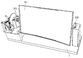
次に、図2乃至図5に基づいて反射ユニット5を説明する。反射ユニット5は、反射部51と、ホルダ52と、支持部53とを有する。
反射部51は、例えば、合成樹脂材料からなる基材の表面に蒸着等の手段により反射膜を形成した凹面鏡からなる。反射部51の反射面は、ウインドシールド7の形状に対応した曲面を有し、乗員Pから見える虚像の歪みを補正する作用も有する。
ホルダ52は、例えば、黒色の金属材料からなり、両端側に突出する回転軸521や反射部51を載せる載置台522が形成される。この場合、反射部51は、両面テープなどで載置台522に固定される。また、回転軸521の両側には、回転軸521を挿通して軸支するボールベアリング(転がり軸受)54と、このボールベアリング54をハウジング1の所定位置に保持するベアリング保持部55とを設けている。
支持部53は、ボールベアリング54と、ベアリング保持部55とからなり、予めこれらを組み付けてから回転軸521に挿通され、さらにハウジング1に保持される。支持部53によって、ハウジング1に対して反射部51を回転可能に軸支できる。この場合、支持部53は、同様のものが3つ用意される。
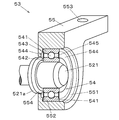
ボールベアリング54は、円筒状の外輪541と、この外輪541の内側に設けられ回転軸521を挿通する孔部を有する内輪542と、外輪541と内輪542との間に介在して円滑な回転を促すボール543と、内輪542と外輪541との隙間を覆うように外輪541に嵌め込まれて設けられるカバー544と、カバー544の内側に内輪542及び外輪541とボール543とが潤滑する潤滑剤545と、を備えている。
ベアリング保持部55は、ボールベアリング54の外輪541が嵌まって収まる孔551と、この外輪541の組み付け位置を規定する壁部552と、ハウジング1の所定箇所にボルト56を用いて保持するための穴部553とを備えている。
ベアリング保持部55は、ボールベアリング54が孔551に圧入されて、これを保持できる。この際、ボールベアリング54は、外輪541が孔551の開口側から、図示しない圧入用治具によって押圧されて挿入され、壁部552に当接する位置まで圧入される。また、この圧入用治具及び壁部552は、外輪541に当たり、内輪542に当たらないような形状、及び組み付け方法が適用され、内輪542に押圧力が加わりボール543が外れたり傷つくなどのボールベアリング54の不具合を防止する。
ボールベアリング54を収納保持したベアリング保持部55は、更に圧入用治具を用いてボールベアリング54の内輪542及びフランジ部521aを挟むようにして、ボールベアリング54の内輪542が回転軸521に挿通しながら圧入されて組み付けられる。
また、組み付け状態において、壁部552は、窓部554とフランジ部521aとの隙間を狭めるように延びており、仮に、カバー544に不具合が生じるなどしても、この壁部552やフランジ部521aによって、潤滑剤545が、反射部51側へ飛散することを防止できる。また、壁部552やフランジ部521aの構造は、組み付け後のエアーブロー工程においても、潤滑剤545が反射部51側へ飛散するのを妨げる構造となる。
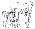
このボールベアリング54を収納保持したベアリング保持部55は、同様のものが反射部51の両側の回転軸521に挿通されて設けられ、アクチュエータ6側の回転軸521には、さらにもう一つのベアリング保持部55が設けられる。従って、ベアリング保持部55は、アクチュエータ6と反射部51との間に複数設けられることになり、反射部51(反射部51両脇のボールベアリング54間)での振動をアクチュエータ6側に伝えにくくしている。
アクチュエータ6は、図5に示すように、モータ61や複数のギア62を備えており、モータ61の回動がギア62を介して回転軸521に伝わるようにしている。ギア62の一つは、回転軸521において複数のベアリング保持部55のさらに端部側(外側)に嵌合して設けられ、回転軸521とともに回動する。さらにモータ61の回動がこのギア62に減速して伝わるように他のギア62が用意される。
これら構成によって、反射部51の大型化にともなって両端側のボールベアリング54による軸支間の距離が長く、車両の振動に応じて共振するなどして載置台522が撓み易くなった場合であっても、上述したようにアクチュエータ6と反射部51との間に複数のボールベアリング54を設けることで、回転軸521の変形を抑止し、振動がギア62側へ伝わることを抑制できる。これにより、例えば、ギア同士が当たって打音が発生してしまうなどの不具合を防止できる。また、走行中であっても、モータ61の駆動力をきちんと回転軸521に伝えることができるため、反射部51を滑らかに回動できる。
斯かるヘッドアップディスプレイ装置Aは、
透光性カバー(出射部)9が形成されたハウジング(筐体)1に、
表示光Lを出力する表示ユニット(表示手段)2と、
表示光Lを透光性カバー9側へ反射する反射部51と反射部51の両端側に突出する一対の回転軸521とを設ける反射ユニット(反射手段)5と、
前記一対の回転軸521の一方側に、回転軸521を回転させることによって反射部51による反射角度を調整するアクチュエータ(駆動手段)6と、
前記一対の回転軸521の両側に、回転軸521が挿通される内輪542とハウジング1側に保持される外輪541とを有するボールベアリング(転がり軸受)54と、を備え、
前記一対の回転軸521のうちアクチュエータ6が設けられる側には、複数のボールベアリング54が設けられる。
透光性カバー(出射部)9が形成されたハウジング(筐体)1に、
表示光Lを出力する表示ユニット(表示手段)2と、
表示光Lを透光性カバー9側へ反射する反射部51と反射部51の両端側に突出する一対の回転軸521とを設ける反射ユニット(反射手段)5と、
前記一対の回転軸521の一方側に、回転軸521を回転させることによって反射部51による反射角度を調整するアクチュエータ(駆動手段)6と、
前記一対の回転軸521の両側に、回転軸521が挿通される内輪542とハウジング1側に保持される外輪541とを有するボールベアリング(転がり軸受)54と、を備え、
前記一対の回転軸521のうちアクチュエータ6が設けられる側には、複数のボールベアリング54が設けられる。
従って、反射部51が大型化しても、ボールベアリング54を用いて滑らかに回動させることができるだけでなく、反射ユニット5を回動させるための駆動力も低減できるため、出力の小さなアクチュエータ6を適用することもできる。また、車両の走行においても、反射部51や載置台522の振動がアクチュエータ6側へ伝わることを防止できるため、上述のように異音の発生も防止でき、また、アクチュエータ6による反射部51の滑らかな回動を維持できる。
また、アクチュエータ6は、ボールベアリング54の外側に備え、反射部51や載置台522の近くで回転軸支することで、軸支間の距離をできるだけ小さくし、撓み量(振幅)を最小限にできる。従って、発生する共振等の振動を抑えることができる。
なお、本発明のヘッドアップディスプレイ装置Aを上述した実施の形態の構成にて例に挙げて説明したが、本発明はこれに限定されるものではなく、他の構成においても、本発明の要旨を逸脱しない範囲において種々の改良、並びに表示の変更が可能なことは勿論である。例えば、上述実施の形態にあっては、バックライトユニット3の照射光を利用して表示像を形成する液晶パネルを用いるものを例に挙げて説明したが、照明光としてレーザー光を走査させて適用したり、DMD(デジタルミラーデバイス)を利用したプロジェクタ方式を適用することもでき、上記ミラーユニットを組み合わせることで、上述実施の形態と同様の効果を得ることができる。
本発明は、ヘッドアップディスプレイ装置に関して、例えば、自動車やオートバイ、あるいは農業機械や建設機械を備えた移動体に搭載される車両情報やターンバイターン表示等の道路情報などの車載表示装置として好適である。
A ヘッドアップディスプレイ装置(車載投影装置)
1 ハウジング(筐体)
2 表示ユニット(表示手段)
3 バックライトユニット
4 平面鏡
5 反射ユニット(反射手段)
51 反射部
52 ホルダ
521 回転軸
53 支持部
54 ボールベアリング(転がり軸受)
541 外輪
542 内輪
543 ボール
544 カバー
545 潤滑剤
55 ベアリング保持部
551 孔
552 壁部
553 穴部
554 窓部
6 アクチュエータ(駆動手段)
7 ウインドシールド
8 出射部
9 透光性カバー(出射部)
1 ハウジング(筐体)
2 表示ユニット(表示手段)
3 バックライトユニット
4 平面鏡
5 反射ユニット(反射手段)
51 反射部
52 ホルダ
521 回転軸
53 支持部
54 ボールベアリング(転がり軸受)
541 外輪
542 内輪
543 ボール
544 カバー
545 潤滑剤
55 ベアリング保持部
551 孔
552 壁部
553 穴部
554 窓部
6 アクチュエータ(駆動手段)
7 ウインドシールド
8 出射部
9 透光性カバー(出射部)
Claims (2)
- 出射部が形成された筐体に、
表示光を出力する表示手段と、
前記表示光を前記出射部側へ反射する反射部と前記反射部の両端側に突出する一対の回転軸とを設ける反射手段と、
前記一対の回転軸の一方側に、前記回転軸を回転させることによって前記反射部による反射角度を調整する駆動手段と、
前記一対の回転軸の両側に、前記回転軸が挿通される内輪と前記筐体側に保持される外輪とを有する転がり軸受と、
を備え、
前記一対の回転軸のうち前記駆動手段が設けられる側には、複数の前記転がり軸受が設けられることを特徴とする車載投影装置。 - 前記駆動手段は、前記転がり軸受の外側に備えることを特徴とする請求項1に記載の車載投影装置。
Applications Claiming Priority (2)
| Application Number | Priority Date | Filing Date | Title |
|---|---|---|---|
| JP2016-107265 | 2016-05-30 | ||
| JP2016107265 | 2016-05-30 |
Publications (1)
| Publication Number | Publication Date |
|---|---|
| WO2017208960A1 true WO2017208960A1 (ja) | 2017-12-07 |
Family
ID=60477501
Family Applications (1)
| Application Number | Title | Priority Date | Filing Date |
|---|---|---|---|
| PCT/JP2017/019520 Ceased WO2017208960A1 (ja) | 2016-05-30 | 2017-05-25 | 車載投影装置 |
Country Status (1)
| Country | Link |
|---|---|
| WO (1) | WO2017208960A1 (ja) |
Citations (6)
| Publication number | Priority date | Publication date | Assignee | Title |
|---|---|---|---|---|
| JP2001117042A (ja) * | 1999-10-20 | 2001-04-27 | Canon Inc | 光偏向走査装置 |
| JP2004276648A (ja) * | 2003-03-12 | 2004-10-07 | Calsonic Kansei Corp | ヘッドアップディスプレイの収納構造 |
| JP2009185917A (ja) * | 2008-02-07 | 2009-08-20 | Sii Micro Precision Kk | 軸受ユニットおよびピボット装置 |
| JP2011150099A (ja) * | 2010-01-21 | 2011-08-04 | Nippon Seiki Co Ltd | ミラーユニット |
| JP2012035736A (ja) * | 2010-08-06 | 2012-02-23 | Toyota Motor Corp | ヘッドアップディスプレイ装置 |
| JP2012056334A (ja) * | 2010-09-03 | 2012-03-22 | Yazaki Corp | ヘッドアップディスプレイ |
-
2017
- 2017-05-25 WO PCT/JP2017/019520 patent/WO2017208960A1/ja not_active Ceased
Patent Citations (6)
| Publication number | Priority date | Publication date | Assignee | Title |
|---|---|---|---|---|
| JP2001117042A (ja) * | 1999-10-20 | 2001-04-27 | Canon Inc | 光偏向走査装置 |
| JP2004276648A (ja) * | 2003-03-12 | 2004-10-07 | Calsonic Kansei Corp | ヘッドアップディスプレイの収納構造 |
| JP2009185917A (ja) * | 2008-02-07 | 2009-08-20 | Sii Micro Precision Kk | 軸受ユニットおよびピボット装置 |
| JP2011150099A (ja) * | 2010-01-21 | 2011-08-04 | Nippon Seiki Co Ltd | ミラーユニット |
| JP2012035736A (ja) * | 2010-08-06 | 2012-02-23 | Toyota Motor Corp | ヘッドアップディスプレイ装置 |
| JP2012056334A (ja) * | 2010-09-03 | 2012-03-22 | Yazaki Corp | ヘッドアップディスプレイ |
Similar Documents
| Publication | Publication Date | Title |
|---|---|---|
| JP6941816B2 (ja) | 回転装置およびヘッドアップディスプレイ装置 | |
| JP6402278B2 (ja) | 投写型表示装置 | |
| JP2017068190A (ja) | ヘッドアップディスプレイ装置 | |
| WO2014065097A1 (ja) | ヘッドアップディスプレイ装置 | |
| JP6836718B2 (ja) | ヘッドアップディスプレイ装置 | |
| EP3677948B1 (en) | Head-up display apparatus | |
| JP6254988B2 (ja) | ヘッドアップディスプレイ装置 | |
| JP5115784B2 (ja) | ヘッドアップディスプレイ装置 | |
| JP2015102700A (ja) | 表示装置 | |
| JP6670445B2 (ja) | 車載投影装置 | |
| JP6733470B2 (ja) | ヘッドアップディスプレイ装置のミラーユニット | |
| JP2017102230A (ja) | ミラーユニット | |
| JP2018140693A (ja) | 車両用ヘッドアップディスプレイ装置 | |
| JP2017219716A (ja) | ミラーユニット | |
| JP2017090667A (ja) | ヘッドアップディスプレイ装置 | |
| JP2017207543A (ja) | ヘッドアップディスプレイ装置 | |
| JP6787010B2 (ja) | ヘッドアップディスプレイ装置のミラーユニット | |
| JP2020019287A (ja) | ヘッドアップディスプレイ装置 | |
| JP5257159B2 (ja) | ヘッドアップディスプレイ装置 | |
| JPWO2020129777A1 (ja) | 凹面鏡支持装置及び表示装置 | |
| JP2019162904A (ja) | ヘッドアップディスプレイ装置のミラー支持構造 | |
| JP2017177880A (ja) | 表示装置 | |
| WO2025220354A1 (ja) | 車両用表示装置 | |
| JPWO2020054550A1 (ja) | ヘッドアップディスプレイ装置 | |
| JP2025036881A (ja) | ヘッドアップディスプレイ装置 |
Legal Events
| Date | Code | Title | Description |
|---|---|---|---|
| 121 | Ep: the epo has been informed by wipo that ep was designated in this application |
Ref document number: 17806517 Country of ref document: EP Kind code of ref document: A1 |
|
| NENP | Non-entry into the national phase |
Ref country code: DE |
|
| 122 | Ep: pct application non-entry in european phase |
Ref document number: 17806517 Country of ref document: EP Kind code of ref document: A1 |
|
| NENP | Non-entry into the national phase |
Ref country code: JP |