WO2017208751A1 - リレー装置及び電源装置 - Google Patents
リレー装置及び電源装置 Download PDFInfo
- Publication number
- WO2017208751A1 WO2017208751A1 PCT/JP2017/017631 JP2017017631W WO2017208751A1 WO 2017208751 A1 WO2017208751 A1 WO 2017208751A1 JP 2017017631 W JP2017017631 W JP 2017017631W WO 2017208751 A1 WO2017208751 A1 WO 2017208751A1
- Authority
- WO
- WIPO (PCT)
- Prior art keywords
- unit
- switch unit
- power storage
- switch
- storage unit
- Prior art date
Links
Images


Classifications
-
- H—ELECTRICITY
- H02—GENERATION; CONVERSION OR DISTRIBUTION OF ELECTRIC POWER
- H02J—CIRCUIT ARRANGEMENTS OR SYSTEMS FOR SUPPLYING OR DISTRIBUTING ELECTRIC POWER; SYSTEMS FOR STORING ELECTRIC ENERGY
- H02J7/00—Circuit arrangements for charging or depolarising batteries or for supplying loads from batteries
- H02J7/14—Circuit arrangements for charging or depolarising batteries or for supplying loads from batteries for charging batteries from dynamo-electric generators driven at varying speed, e.g. on vehicle
- H02J7/1423—Circuit arrangements for charging or depolarising batteries or for supplying loads from batteries for charging batteries from dynamo-electric generators driven at varying speed, e.g. on vehicle with multiple batteries
-
- B—PERFORMING OPERATIONS; TRANSPORTING
- B60—VEHICLES IN GENERAL
- B60R—VEHICLES, VEHICLE FITTINGS, OR VEHICLE PARTS, NOT OTHERWISE PROVIDED FOR
- B60R16/00—Electric or fluid circuits specially adapted for vehicles and not otherwise provided for; Arrangement of elements of electric or fluid circuits specially adapted for vehicles and not otherwise provided for
- B60R16/02—Electric or fluid circuits specially adapted for vehicles and not otherwise provided for; Arrangement of elements of electric or fluid circuits specially adapted for vehicles and not otherwise provided for electric constitutive elements
- B60R16/03—Electric or fluid circuits specially adapted for vehicles and not otherwise provided for; Arrangement of elements of electric or fluid circuits specially adapted for vehicles and not otherwise provided for electric constitutive elements for supply of electrical power to vehicle subsystems or for
- B60R16/033—Electric or fluid circuits specially adapted for vehicles and not otherwise provided for; Arrangement of elements of electric or fluid circuits specially adapted for vehicles and not otherwise provided for electric constitutive elements for supply of electrical power to vehicle subsystems or for characterised by the use of electrical cells or batteries
-
- G—PHYSICS
- G01—MEASURING; TESTING
- G01R—MEASURING ELECTRIC VARIABLES; MEASURING MAGNETIC VARIABLES
- G01R31/00—Arrangements for testing electric properties; Arrangements for locating electric faults; Arrangements for electrical testing characterised by what is being tested not provided for elsewhere
- G01R31/005—Testing of electric installations on transport means
- G01R31/006—Testing of electric installations on transport means on road vehicles, e.g. automobiles or trucks
-
- G—PHYSICS
- G01—MEASURING; TESTING
- G01R—MEASURING ELECTRIC VARIABLES; MEASURING MAGNETIC VARIABLES
- G01R31/00—Arrangements for testing electric properties; Arrangements for locating electric faults; Arrangements for electrical testing characterised by what is being tested not provided for elsewhere
- G01R31/50—Testing of electric apparatus, lines, cables or components for short-circuits, continuity, leakage current or incorrect line connections
-
- H—ELECTRICITY
- H01—ELECTRIC ELEMENTS
- H01H—ELECTRIC SWITCHES; RELAYS; SELECTORS; EMERGENCY PROTECTIVE DEVICES
- H01H47/00—Circuit arrangements not adapted to a particular application of the relay and designed to obtain desired operating characteristics or to provide energising current
- H01H47/002—Monitoring or fail-safe circuits
-
- H—ELECTRICITY
- H01—ELECTRIC ELEMENTS
- H01M—PROCESSES OR MEANS, e.g. BATTERIES, FOR THE DIRECT CONVERSION OF CHEMICAL ENERGY INTO ELECTRICAL ENERGY
- H01M10/00—Secondary cells; Manufacture thereof
- H01M10/42—Methods or arrangements for servicing or maintenance of secondary cells or secondary half-cells
- H01M10/44—Methods for charging or discharging
-
- H—ELECTRICITY
- H01—ELECTRIC ELEMENTS
- H01M—PROCESSES OR MEANS, e.g. BATTERIES, FOR THE DIRECT CONVERSION OF CHEMICAL ENERGY INTO ELECTRICAL ENERGY
- H01M10/00—Secondary cells; Manufacture thereof
- H01M10/42—Methods or arrangements for servicing or maintenance of secondary cells or secondary half-cells
- H01M10/48—Accumulators combined with arrangements for measuring, testing or indicating the condition of cells, e.g. the level or density of the electrolyte
-
- H—ELECTRICITY
- H02—GENERATION; CONVERSION OR DISTRIBUTION OF ELECTRIC POWER
- H02H—EMERGENCY PROTECTIVE CIRCUIT ARRANGEMENTS
- H02H7/00—Emergency protective circuit arrangements specially adapted for specific types of electric machines or apparatus or for sectionalised protection of cable or line systems, and effecting automatic switching in the event of an undesired change from normal working conditions
- H02H7/18—Emergency protective circuit arrangements specially adapted for specific types of electric machines or apparatus or for sectionalised protection of cable or line systems, and effecting automatic switching in the event of an undesired change from normal working conditions for batteries; for accumulators
-
- H—ELECTRICITY
- H02—GENERATION; CONVERSION OR DISTRIBUTION OF ELECTRIC POWER
- H02J—CIRCUIT ARRANGEMENTS OR SYSTEMS FOR SUPPLYING OR DISTRIBUTING ELECTRIC POWER; SYSTEMS FOR STORING ELECTRIC ENERGY
- H02J7/00—Circuit arrangements for charging or depolarising batteries or for supplying loads from batteries
- H02J7/0029—Circuit arrangements for charging or depolarising batteries or for supplying loads from batteries with safety or protection devices or circuits
- H02J7/00304—Overcurrent protection
-
- H—ELECTRICITY
- H02—GENERATION; CONVERSION OR DISTRIBUTION OF ELECTRIC POWER
- H02J—CIRCUIT ARRANGEMENTS OR SYSTEMS FOR SUPPLYING OR DISTRIBUTING ELECTRIC POWER; SYSTEMS FOR STORING ELECTRIC ENERGY
- H02J7/00—Circuit arrangements for charging or depolarising batteries or for supplying loads from batteries
- H02J7/0047—Circuit arrangements for charging or depolarising batteries or for supplying loads from batteries with monitoring or indicating devices or circuits
-
- H—ELECTRICITY
- H02—GENERATION; CONVERSION OR DISTRIBUTION OF ELECTRIC POWER
- H02J—CIRCUIT ARRANGEMENTS OR SYSTEMS FOR SUPPLYING OR DISTRIBUTING ELECTRIC POWER; SYSTEMS FOR STORING ELECTRIC ENERGY
- H02J7/00—Circuit arrangements for charging or depolarising batteries or for supplying loads from batteries
- H02J7/14—Circuit arrangements for charging or depolarising batteries or for supplying loads from batteries for charging batteries from dynamo-electric generators driven at varying speed, e.g. on vehicle
- H02J7/1438—Circuit arrangements for charging or depolarising batteries or for supplying loads from batteries for charging batteries from dynamo-electric generators driven at varying speed, e.g. on vehicle in combination with power supplies for loads other than batteries
-
- B—PERFORMING OPERATIONS; TRANSPORTING
- B60—VEHICLES IN GENERAL
- B60R—VEHICLES, VEHICLE FITTINGS, OR VEHICLE PARTS, NOT OTHERWISE PROVIDED FOR
- B60R16/00—Electric or fluid circuits specially adapted for vehicles and not otherwise provided for; Arrangement of elements of electric or fluid circuits specially adapted for vehicles and not otherwise provided for
- B60R16/02—Electric or fluid circuits specially adapted for vehicles and not otherwise provided for; Arrangement of elements of electric or fluid circuits specially adapted for vehicles and not otherwise provided for electric constitutive elements
- B60R16/03—Electric or fluid circuits specially adapted for vehicles and not otherwise provided for; Arrangement of elements of electric or fluid circuits specially adapted for vehicles and not otherwise provided for electric constitutive elements for supply of electrical power to vehicle subsystems or for
-
- H—ELECTRICITY
- H02—GENERATION; CONVERSION OR DISTRIBUTION OF ELECTRIC POWER
- H02J—CIRCUIT ARRANGEMENTS OR SYSTEMS FOR SUPPLYING OR DISTRIBUTING ELECTRIC POWER; SYSTEMS FOR STORING ELECTRIC ENERGY
- H02J2310/00—The network for supplying or distributing electric power characterised by its spatial reach or by the load
- H02J2310/40—The network being an on-board power network, i.e. within a vehicle
- H02J2310/46—The network being an on-board power network, i.e. within a vehicle for ICE-powered road vehicles
-
- H—ELECTRICITY
- H02—GENERATION; CONVERSION OR DISTRIBUTION OF ELECTRIC POWER
- H02J—CIRCUIT ARRANGEMENTS OR SYSTEMS FOR SUPPLYING OR DISTRIBUTING ELECTRIC POWER; SYSTEMS FOR STORING ELECTRIC ENERGY
- H02J7/00—Circuit arrangements for charging or depolarising batteries or for supplying loads from batteries
- H02J7/34—Parallel operation in networks using both storage and other dc sources, e.g. providing buffering
- H02J7/345—Parallel operation in networks using both storage and other dc sources, e.g. providing buffering using capacitors as storage or buffering devices
-
- Y—GENERAL TAGGING OF NEW TECHNOLOGICAL DEVELOPMENTS; GENERAL TAGGING OF CROSS-SECTIONAL TECHNOLOGIES SPANNING OVER SEVERAL SECTIONS OF THE IPC; TECHNICAL SUBJECTS COVERED BY FORMER USPC CROSS-REFERENCE ART COLLECTIONS [XRACs] AND DIGESTS
- Y02—TECHNOLOGIES OR APPLICATIONS FOR MITIGATION OR ADAPTATION AGAINST CLIMATE CHANGE
- Y02E—REDUCTION OF GREENHOUSE GAS [GHG] EMISSIONS, RELATED TO ENERGY GENERATION, TRANSMISSION OR DISTRIBUTION
- Y02E60/00—Enabling technologies; Technologies with a potential or indirect contribution to GHG emissions mitigation
- Y02E60/10—Energy storage using batteries
Definitions
- the present invention relates to a relay device and a power supply device for switching power supply from a generator.
- Patent Document 1 discloses an example of an in-vehicle power supply device.
- the power supply device disclosed in Patent Document 1 includes a lead storage battery and a lithium storage battery, and a power supply line is provided as a power path between the lead storage battery and the lithium storage battery.
- Two MOSFETs for switching between energization and interruption of the power supply line are provided.
- the SOC is in the optimum range by switching the MOSFET on and off in accordance with the SOC (State of charge) of the lithium storage battery during non-regenerative operation (during idle operation, acceleration traveling, steady traveling, etc.). To control.
- the system of Patent Document 1 is a system that switches between energization and non-energization between two power storage units by a relay.
- a relay In such a system, for example, when an abnormality occurs in one power supply system, the influence of the abnormality is affected. As a result, there is a possibility that an appropriate operating voltage is not supplied to both power systems.
- the relay when the alternator is connected to the power line on the main battery (lead storage battery) side and the charge amount of the sub-battery (lithium storage battery) is insufficient, the relay is maintained in the on state.
- the sub-battery can be charged by supplying electric power.
- the main battery and sub-battery are completely conducted by the ON operation of the relay, so that when a ground fault occurs in the power supply system on one side of the relay, the effect instantaneously reaches the other side of the relay. In the other power supply system, the voltage suddenly drops. That is, since the battery voltage instantaneously decreases in both power supply systems, an appropriate operating voltage cannot be supplied to the load from either power supply system.
- the present invention has been made based on the above-described circumstances, and can supply a charging current from a generator to at least two power storage units, and when an abnormality occurs on one power storage unit side,
- An object of the present invention is to provide a relay device and a power supply device that can suppress an abnormality from reaching the other power storage unit side.
- the relay device of the present invention is A first switch unit that switches a first conductive path serving as a path between the generator and the first power storage unit between an energization allowable state and an energization cut-off state; A second switch unit that switches a second conductive path serving as a path between the generator and the second power storage unit between an energization allowable state and an energization cut-off state; A series circuit in which one end is electrically connected between the first switch unit and the first power storage unit, and the other end is electrically connected between the second switch unit and the second power storage unit. A bypass unit in which the resistor unit and the third switch unit are connected in series in the series circuit; A control unit for controlling on / off of the first switch unit, the second switch unit, and the third switch unit; Have
- the relay device of the present invention can efficiently supply a charging current based on the generated power of the generator to the first power storage unit by turning on the first switch unit and turning off the second switch unit.
- a ground fault occurs on the first power storage unit side
- the third switch unit is in an off state
- the ground fault occurrence part and the conductive path on the second power storage unit side are in an insulated state, so the second power storage unit
- the voltage drop of the conductive path on the side can be prevented.
- the resistance unit is interposed between the ground fault occurrence part and the conductive path on the second power storage unit side. A voltage drop in the conductive path on the power storage unit side can be suppressed.
- the third switch unit is in the OFF state, the ground fault occurrence part and the conductive path on the first power storage unit side are Since it is in an insulating state, it is possible to prevent a voltage drop in the conductive path on the first power storage unit side.
- the resistance unit is interposed between the ground fault occurrence part and the conductive path on the first power storage unit side, so the voltage drop on the first power storage unit side Can be suppressed.
- the relay device can efficiently supply the charging current based on the power generated by the generator to the second power storage unit by turning on the second switch unit and turning off the first switch unit.
- the third switch unit is in an off state, the ground fault occurrence part and the conductive path on the second power storage unit side are in an insulated state, so the second power storage unit The voltage drop of the conductive path on the side can be prevented.
- the resistance unit is interposed between the ground fault occurrence part and the conductive path on the second power storage unit side. A voltage drop in the conductive path on the power storage unit side can be suppressed.
- the third switch unit is in the OFF state, the ground fault occurrence part and the conductive path on the first power storage unit side are Since it is in an insulating state, it is possible to prevent a voltage drop in the conductive path on the first power storage unit side.
- the resistance unit is interposed between the ground fault occurrence part and the conductive path on the first power storage unit side, so the voltage drop on the first power storage unit side Can be suppressed.
- the above-described invention may be configured such that when the first switch unit is turned on, the second switch unit is always turned off, and when the second switch unit is turned on, the first switch unit is always turned off.
- the first control for turning on the first switch part and turning off the second switch part and the second control for turning on the second switch part and turning off the first switch part but also the first switch
- movement of both a part and a 2nd switch part may be sufficient.
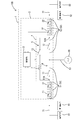
- FIG. 1 is a circuit diagram schematically illustrating an in-vehicle power supply system equipped with a relay device and a power supply device according to a first embodiment.
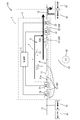
- FIG. 2 is a circuit diagram specifically illustrating a representative example of a relay device and a power supply device in the in-vehicle power supply system shown in FIG. 1. It is explanatory drawing explaining the operation
- FIG. 3 is an explanatory diagram for explaining a case where a ground fault occurs in the wiring on the first power storage unit side during the first control in the in-vehicle power supply system of FIG. 1.
- the control unit may perform control so that the second switch unit is always turned off at least when the first switch unit is turned on, and the first switch unit is always turned off at least when the second switch unit is turned on.
- the first power storage unit and the first power storage unit can be switched by always turning off the second switch unit when the first switch unit is on, and always turning off the first switch unit when the second switch unit is on. It is possible to prevent a state in which electrical connection is established between the second power storage unit and the second power storage unit via the first switch unit and the second switch unit.
- the control unit turns off the second switch unit and turns on the third switch unit at least when the first switch unit is turned on, and turns off the first switch unit and turns on the third switch unit at least when the second switch unit is turned on.
- the control may be performed so that the three-switch unit is turned on.
- the charging current from the generator is efficiently supplied to the first power storage unit via the first switch unit, and more than this via the bypass unit.
- a relatively small charging current can be supplied to the second power storage unit.
- the first power storage unit is not connected between the first power storage unit and the second power storage unit via the first switch unit and the second switch unit.
- a resistance portion is interposed between the conductive path on the side and the conductive path on the second power storage unit side. Therefore, even if a ground fault occurs on one power storage unit side, the voltage drop on the other power storage unit side can be suppressed by the resistance component of the resistance unit. This effect is the same even when the second switch unit is turned on.
- the charging current from the generator is efficiently charged to the second power storage unit via the second switch unit, and a relatively smaller charging current is supplied to the first power storage via the bypass unit. It can supply also to a part. Also in this case, since the resistance portion is interposed between the conductive path on the first power storage unit side and the conductive path on the second power storage unit side, a ground fault occurs on one of the power storage units side. In addition, the voltage drop on the other power storage unit side can be suppressed by the resistance component of the resistance unit.
- the relay device may include a detection unit that detects at least one of current and voltage in at least one of the first conductive path and the second conductive path.
- the control unit may be configured to switch the third switch unit to the off state when the detection value of the detection unit is within a predetermined abnormal range when at least the third switch unit is in the on state.
- the third switch unit when an abnormality occurs on one of the power storage units when the third switch unit is in the on state, the third switch unit can be switched to the off state. Thereby, the flow of current through the bypass portion can be blocked. In addition, since the first switch unit and the second switch unit are not turned on at the same time, the flow from the path through the first switch unit and the second switch unit is also blocked. In addition, voltage fluctuations that occur on the other power storage unit side (normal power storage unit side) before switching the third switch unit to the off state can be suppressed by the resistance component of the resistance unit provided in the bypass unit, The other power storage unit side (normal power storage unit side) can be separated from the short circuit abnormal part while suppressing the influence of the abnormality.
- the power supply device may be configured to include any of the relay devices described above and the second power storage unit electrically connected thereto.
- a power supply system 100 shown in FIG. 1 is configured as an in-vehicle power supply system including a first power storage unit 91 and a second power storage unit 92 mounted on a vehicle.
- Relay device 2 forms part of power supply system 100 and has a function of switching between first power storage unit 91 and second power storage unit 92 between an energized state and a non-energized state.
- a first electric load 81 that is a main load and a second electric load 82 that is an auxiliary load are provided, and the first electric load 81 and the second electric load 82 are included.
- a configuration in which the electrical load 82 has an equivalent function will be described as a representative example. However, this is merely a representative example, and the application target of the relay device 2 is not limited to this configuration.
- the first electric load 81 that functions as the main load is, for example, an electric power steering system, and has a configuration in which an electric component such as a motor operates upon receiving power supply from the first power storage unit 91.
- the second electric load 82 that functions as a sub load is an electric power steering system having the same configuration and function as the first electric load 81.
- the power supply system 100 operates the second electric load 82 instead of the first electric load 81 when an abnormality occurs in the first electric load 81, so that even when the first electric load 81 is abnormal.
- the system is configured as a system capable of maintaining the function of the first electric load 81.
- the 1st electrical storage part 91 is a power supply part which can supply electric power to the 1st electric load 81, for example, is comprised by well-known power supplies, such as a lead battery.
- the second power storage unit 92 is a power source unit that can supply power to the second electric load 82, and is configured by a known power source such as a lithium ion battery or an electric double layer capacitor.
- the in-vehicle power supply device 1 (hereinafter also simply referred to as the power supply device 1) is configured to include the second power storage unit 92 and a relay device 2 described later.
- the relay device 2 and the second power storage unit 92 are configured as an integral unit.
- the relay device 2 and the second power storage unit 92 are configured as an integral unit, and the relay device 2 and the second power storage unit 92 may be fixed to a common frame.
- the relay device 2 and the second power storage unit 92 may be housed in a common case, or the second power storage unit 92 may be mounted on a substrate that forms part of the relay device 2. May be.
- the first power storage unit 91 and the first electric load 81 are electrically connected to a wiring 71 provided outside the relay device 2.
- the wiring 71 is made of, for example, a wire or the like, and is electrically connected to a first conductive path 51 (to be described later) and is electrically connected to one end side of the relay unit 4 via the first conductive path 51.
- the second power storage unit 92 and the second electric load 82 are electrically connected to a wiring 72 provided outside the relay device 2.
- the wiring 72 is made of, for example, a wire or the like, and is electrically connected to a second conductive path 52 to be described later and electrically connected to the other end side of the relay unit 4 via the second conductive path 52.
- the generator 95 is configured as a known alternator, and operates at a predetermined time and applies a generated voltage to the wiring 53.
- the generator 95 is configured to be capable of deceleration energy regeneration control, and is configured to be able to use the regeneration energy at the time of deceleration, for example, for charging the first power storage unit 91.
- the wiring 53 is a path for supplying power generated by the generator 95, and is configured by, for example, a wire or a wiring pattern, and is electrically connected to a conductive path between the first switch unit 11 and the second switch unit 12 described later. It is connected.
- the conductive path that branches from the end of the wiring 53 to the first power storage unit 91 side is the first conductive path 51, and the conductive path that branches from the end of the wiring 53 to the second power storage unit 92 side.
- the path is the second conductive path 52.
- the relay device 2 includes a first conductive path 51, a second conductive path 52, a relay unit 4, a first voltage detection unit 21 (voltage monitor), a first current detection unit 31 (current monitor), and a second A voltage detection unit 22 (voltage monitor), a second current detection unit 32 (current monitor), and a control unit 3 are provided.
- the relay device 2 is configured, for example, as a circuit board in which various electronic components are mounted on a board body, the first conductive path 51 is connected to the wiring 71 via a terminal (not shown), and the second conductive path 52 is a terminal (not shown). It is connected to the wiring 72 via.
- the first conductive path 51 has one end connected to the wiring 53 and the other end connected to the wiring 71 on the first power storage unit 91 side, and is electrically connected to the first power storage unit 91 via the wiring 71. Yes.
- the first conductive path 51 is a power line, and becomes a path through which a charging current supplied to the first power storage unit 91 flows based on the generated power from the generator 95 when the first switch unit 11 is turned on.
- a first voltage detection unit 21 and a first current detection unit 31 described later are interposed in the first conductive path 51.
- the second conductive path 52 is connected to the wiring 72 on the second power storage unit 92 side, and is electrically connected to the second power storage unit 92 via the wiring 72.
- the second conductive path 52 is a power line and serves as a path through which a charging current supplied to the second power storage unit 92 flows based on the generated power from the generator 95 when the second switch unit 12 is turned on.
- a second voltage detector 22 and a second current detector 32 described later are interposed in the second conductive path 52.
- the relay unit 4 includes a first switch unit 11, a second switch unit 12, and a bypass unit 5.
- the first switch unit 11 is configured by, for example, one or a plurality of known semiconductor switch elements, and the first conductive path 51 serving as a path between the generator 95 and the first power storage unit 91 is allowed to be energized and interrupted. It has a function to switch to a state.
- the second switch unit 12 is configured by, for example, one or a plurality of known semiconductor switch elements, and the second conductive path 52 serving as a path between the generator 95 and the second power storage unit 92 is allowed to be energized and interrupted. It has a function to switch to a state.
- the bypass unit 5 includes a series circuit 6 in which a resistor unit 7 and a third switch unit 13 are connected in series.
- One end of the series circuit 6 is electrically connected to a connection portion 51A between the first switch unit 11 and the first power storage unit 91 in the first conductive path 51, and the other end of the series circuit 6 is the second conductive path 52.
- the relay unit 4 conducts the first switch unit 11 and supplies a charging current from the generator 95 to the first power storage unit 91 via the first switch unit 11. Is possible.
- the 1st switch part 11 is an OFF state, the 1st switch part 11 will be in the interruption
- the second switch unit 12 when the second switch unit 12 is in the ON state, the second switch unit 12 becomes conductive, and a charging current can be supplied from the generator 95 to the second power storage unit 92 via the second switch unit 12. It becomes.
- the second switch unit 12 When the second switch unit 12 is in the off state, the second switch unit 12 is in a cut-off state that blocks the flow of current from the generator 95 side to the second power storage unit 92 side via the second switch unit 12.
- Examples of the first switch unit 11, the second switch unit 12, and the third switch unit 13 having such a function include an example as shown in FIG.
- the first switch unit 11 is configured by two MOSFETs 11A and 11B connected in series in different directions.
- the second switch unit 12 is composed of two MOSFETs 12A and 12B connected in series in different directions.
- the third switch unit 13 is composed of two MOSFETs 13A and 13B connected in series in different directions. All of the MOSFETs 11A and 11B constituting the first switch unit 11, the MOSFETs 12A and 12B constituting the second switch unit 12, and the MOSFETs 13A and 13B constituting the third switch unit 13 are in a so-called butted state (the body diodes are opposite to each other). Since the two MOSFETs are in the off state, both switch parts are in a state of interrupting bidirectional energization.
- the voltage value detected by the first voltage detection unit 21 is input to the control unit 3 through a signal line.
- the second voltage detection unit 22 is configured as a known voltage detection circuit (voltage monitor) and has a function of detecting the voltage of the second conductive path 52.
- the voltage value detected by the second voltage detection unit 22 is input to the control unit 3 through a signal line.
- the first current detection unit 31 is configured as a known current detection circuit (current monitor), and has a function of detecting a current flowing through the first conductive path 51.
- the current value detected by the first current detection unit 31 is input to the control unit 3 through a signal line.
- the second current detection unit 32 is configured as a known current detection circuit (current monitor) and has a function of detecting a current flowing through the second conductive path 52.
- the current value detected by the second current detection unit 32 is input to the control unit 3 through a signal line.
- the control unit 3 includes, for example, a microcomputer provided with a CPU, ROM, RAM, A / D converter, and the like.
- the control unit 3 includes a detection value of the first voltage detection unit 21 (voltage value of the first conductive path 51), a detection value of the second voltage detection unit 22 (voltage value of the second conductive path 52), and a first current detection.
- the detection value of the unit 31 (current value of the first conductive path 51) and the detection value of the second current detection unit 32 (current value of the second conductive path 52) are input.
- Each detection value input to the control unit 3 is converted into a digital value by an A / D converter in the control unit 3.
- the control unit 3 controls the on / off of the first switch unit 11, the second switch unit 12, and the third switch unit 13.
- the relay device 2 turns on the first switch unit 11 to charge the first power storage unit 91 when a predetermined first condition is established.
- the timing at which the control unit 3 controls the first switch unit 11 to the on state is not particularly limited, and the number of conditions is not limited to one.
- the control unit 3 continuously monitors the output voltage of the first power storage unit 91 and turns on the first switch unit 11 when the output voltage of the first power storage unit 91 drops below a predetermined first threshold value. You may control to.
- the control unit 3 always or at a predetermined condition (for example, when the output voltage of the first power storage unit 91 is less than a predetermined value) during regenerative control such as when the generator 95 performs regenerative power generation when the vehicle decelerates.
- the first switch unit 11 may be controlled to be in an on state.
- the time for controlling the first switch unit 11 to be in the ON state may be other time.
- the control unit 3 turns off the second switch unit 12 at least when the first switch unit 11 is turned on. That is, the first switch unit 11 and the second switch unit 12 are controlled so as not to be turned on simultaneously. As a result, the conductive path 50 including the first conductive path 51 and the second conductive path 52 is not electrically connected between the connection part 51A and the connection part 52A, and the first power storage part 91 and the second power storage part 92 are not connected. Thus, power is not supplied only through the conductive path 50. That is, current does not flow between the first power storage unit 91 and the second power storage unit 92 unless the bypass unit 5 is interposed.
- the control unit 3 turns on the third switch unit 13 at a time when the first switch unit 11 is turned on, or at a predetermined condition (for example, when the output voltage of the second power storage unit 92 is less than a predetermined value). Make it work.
- a predetermined condition for example, when the output voltage of the second power storage unit 92 is less than a predetermined value.
- the first power storage unit 91 is conceptually shown in FIG. As shown, the charging current from the generator 95 can be efficiently supplied through the first switch unit 11 having a low resistance value, and the second power storage unit 92 can be supplied through the bypass unit 5. Also, a relatively small charging current can be supplied.
- the relay device 2 turns on the second switch unit 12 to charge the second power storage unit 92 when a predetermined second condition is satisfied.
- the timing at which the control unit 3 controls the second switch unit 12 to the on state is not particularly limited, and the number of conditions is not limited to one.
- the control unit 3 continuously monitors the output voltage of the second power storage unit 92, the output voltage of the second power storage unit 92 falls below a predetermined second threshold, and the first switch unit 11.
- the second switch unit 12 may be controlled to be in an on state when the switch is not turned on.
- the control unit 3 always or at a time when the generator 95 performs regenerative power generation when the vehicle decelerates and does not turn on the first switch unit 11 (for example, the output of the second power storage unit 92).
- the second switch unit 12 may be controlled to be turned on when the voltage is less than a predetermined value.
- the time when the second switch unit 12 is controlled to be in the ON state may be other time.
- the control unit 3 turns off the first switch unit 11 at least when the second switch unit 12 is turned on. Also in this case, the first switch unit 11 and the second switch unit 12 are controlled so as not to be turned on simultaneously. Then, the control unit 3 always turns the second switch unit 12 on, or at a predetermined condition (for example, when the output voltage of the first power storage unit 91 is less than a predetermined value), the third switch unit 13. To turn on.
- the second power storage unit 92 is turned off from the generator 95 when the generator 95 generates power. Can be efficiently supplied through the second switch unit 12 having a low resistance value, and a relatively smaller charging current can be supplied to the first power storage unit 91 through the bypass unit 5. can do.
- control unit 3 performs the first control to turn off the second switch unit 12 and turn on the third switch at least when the first switch unit 11 is turned on, and to turn on the second switch unit 12 at least.
- the second control for turning off the first switch unit 11 and turning on the third switch unit 13 can be performed.
- the control unit 3 forcibly controls the first switch unit 11, the second switch unit 12, and the third switch unit 13 provided in the relay unit 4 to be turned off. That is, the switch unit that is in the off state before the occurrence of the predetermined abnormal state is maintained in the off state as it is, and the switch unit that is in the on state before the occurrence of the predetermined abnormal state is immediately switched to the off state.
- the control unit 3 continuously monitors each detection value (each voltage value) input from the first voltage detection unit 21 and the second voltage detection unit 22, and the first voltage detection unit 21 and the first voltage detection unit 21
- the first switch unit 11, the second switch unit 12, and the third switch unit 13 are all turned off when a detection value input from at least one of the two voltage detection units 22 is equal to or lower than a predetermined abnormality threshold Vth.
- the value of the abnormal threshold value Vth is not particularly limited, but can be set to a value lower than, for example, the first threshold value or the second threshold value described above.
- the voltage of the conductive path (that is, the second conductive path 52) arranged on the opposite side of the ground fault generation side across the resistance section 7 is 0 V due to the resistance component of the resistance section 7. It is greatly suppressed without deteriorating to the vicinity.
- the voltage value detected by the first voltage detection unit 21 immediately after the occurrence of the ground fault instantaneously becomes less than the abnormal threshold Vth. Immediately thereafter, it can be determined that there is an abnormality instantaneously. Then, the control unit 3 immediately performs control to turn off all of the first switch unit 11, the second switch unit 12, and the third switch unit 13, and between the first conductive path 51 and the second conductive path 52. Can be cut off quickly.
- the charging current is supplied to both power storage units.
- the voltage drop on the second conductive path 52 side can be suppressed by the resistance component of the resistance section 7 present in the bypass section 5.
- the voltage of the conductive path (that is, the first conductive path 51) arranged on the opposite side of the ground fault generation side across the resistance section 7 is 0 V due to the resistance component of the resistance section 7. It is greatly suppressed without deteriorating to the vicinity.
- the voltage value detected by the second voltage detection unit 22 immediately after the occurrence of the ground fault instantaneously becomes less than the abnormal threshold Vth.
- the control unit 3 immediately performs control to turn off all of the first switch unit 11, the second switch unit 12, and the third switch unit 13, and between the first conductive path 51 and the second conductive path 52. Can be cut off quickly.
- the charging current is supplied to both power storage units.
- the voltage drop on the first conductive path 51 side can be suppressed by the resistance component of the resistance section 7 present in the bypass section 5.
- the above-described specific example of the operation at the time of occurrence of an abnormality is the case where the control unit 3 switches the first switch when the detection value of the first voltage detection unit 21 or the second voltage detection unit 22 becomes an abnormal range during the charge control.
- the unit 11, the second switch unit 12, and the third switch unit 13 are all turned off, the present invention is not limited to this example.
- the detection value of the first current detection unit 31 or the second current detection unit 32 is in an abnormal range during the charge control (for example, a predetermined overcurrent threshold value)
- the control unit 3 may perform control to turn off all of the first switch unit 11, the second switch unit 12, and the third switch unit 13).
- the first voltage detection unit 21, the second voltage detection unit 22, the first current detection unit 31, and the second current detection unit 32 correspond to an example of the detection unit, and the first conductive path 51 and the second conductive path.
- 52 has a function of detecting at least one of a current and a voltage in at least one of 52.
- the control part 3 has a function which switches the 1st switch part 11, the 2nd switch part 12, and the 3rd switch part 13, and, specifically, the 1st switch part 11, the 2nd switch part 12, the 3rd switch The first switch unit 11, the second switch unit 12, and the third switch unit when the detection value of the detection unit is within a predetermined abnormal range corresponding to the ground fault state when at least one of the units 13 is in the on state. Control is performed to turn off all of 13.
- the relay device 2 and the power supply device 1 configured as described above turn on the first switch unit 11 and turn off the second switch unit 12, so that the charging current based on the generated power of the generator 95 is changed to the first. 1 can be efficiently supplied to the power storage unit 91. If a ground fault occurs on the first power storage unit 91 side at this time, if the third switch unit 13 is in an off state, the ground fault generation part and the conductive path on the second power storage unit 92 side are in an insulated state, so 2 A voltage drop in the conductive path on the power storage unit 92 side can be prevented. Even if the third switch unit 13 is in the ON state, the resistance unit 7 is interposed between the ground fault occurrence part and the conductive path on the second power storage unit 92 side.
- the voltage drop of the conductive path on the second power storage unit 92 side can be suppressed by the component.
- a ground fault occurs on the second power storage unit 92 side when the first switch unit 11 is on.
- the third switch unit 13 is off, the ground fault occurrence part and the first power storage unit 91 side Since the conductive path is in an insulated state, a voltage drop in the conductive path on the first power storage unit 91 side can be prevented. Even if the third switch unit 13 is in the ON state, the resistance unit 7 is interposed between the ground fault occurrence part and the conductive path on the first power storage unit 91 side. Side voltage drop can be suppressed.
- the relay device 2 efficiently supplies the charging current based on the power generated by the generator 95 to the second power storage unit 92 by turning on the second switch unit 12 and turning off the first switch unit 11. can do. If a ground fault occurs on the first power storage unit 91 side at this time, if the third switch unit 13 is in an off state, the ground fault generation part and the conductive path on the second power storage unit 92 side are in an insulated state, so 2 A voltage drop in the conductive path on the power storage unit 92 side can be prevented. Even if the third switch unit 13 is in the ON state, the resistance unit 7 is interposed between the ground fault occurrence part and the conductive path on the second power storage unit 92 side.
- the voltage drop of the conductive path on the second power storage unit 92 side can be suppressed by the component.
- a ground fault occurs on the second power storage unit 92 side when the second switch unit 12 is on.
- the third switch unit 13 is off, the ground fault occurrence part and the first power storage unit 91 side Since the conductive path is in an insulated state, a voltage drop in the conductive path on the first power storage unit 91 side can be prevented. Even if the third switch unit 13 is in the ON state, the resistance unit 7 is interposed between the ground fault occurrence part and the conductive path on the first power storage unit 91 side. Side voltage drop can be suppressed.
- the control unit 3 performs control so that the second switch unit 12 is always turned off at least when the first switch unit 11 is turned on, and the first switch unit 11 is always turned off at least when the second switch unit 12 is turned on. Do. In this way, the first switch unit 11 is switched off so that the second switch unit 12 is turned off when the first switch unit 11 is turned on, and the first switch unit 11 is turned off when the second switch unit 12 is turned on. It is possible to prevent a state in which the unit 91 and the second power storage unit 92 are electrically connected via the first switch unit 11 and the second switch unit 12.
- the control unit 3 is configured to be able to perform the first control such that the second switch unit 12 is turned off and the third switch is turned on at least when the first switch unit 11 is turned on.
- the second control can be performed such that the first switch unit 11 is turned off and the third switch unit 13 is turned on during the on operation. According to this configuration, when the first switch unit 11 is turned on, the charging current from the generator 95 is efficiently supplied to the first power storage unit 91 via the first switch unit 11 and the bypass unit 5 is provided. Thus, a relatively smaller charging current can be supplied to the second power storage unit 92.
- the first power storage unit 91 and the second power storage unit 92 are not electrically connected via the first switch unit 11 and the second switch unit 12,
- the resistance unit 7 is interposed between the conductive path on the first power storage unit 91 side and the conductive path on the second power storage unit 92 side. Therefore, even if a ground fault occurs on one of the power storage units, a voltage drop on the other power storage unit can be suppressed by the resistance component of the resistance unit 7. This effect is the same even when the second switch unit 12 is turned on. In this case, the charging current from the generator 95 is efficiently charged to the second power storage unit 92 via the second switch unit 12 and the charging current is relatively smaller than this via the bypass unit 5.
- the relay device 2 includes detection units (a first voltage detection unit 21, a second voltage detection unit 22, a first current detection unit 31, each of which detects a current and a voltage of the first conductive path 51 and the second conductive path 52.
- the control unit 3 is configured to switch the third switch unit 13 to an off state when the detection value of any of the detection units is within a predetermined abnormal range when the third switch unit 13 is in an on state (specifically, The first switch unit 11, the second switch unit 12, and the third switch unit 13 are all turned off. For example, when the detection value of the first voltage detection unit 21 indicates an abnormal value when the third switch unit 13 is on, all of the first switch unit 11, the second switch unit 12, and the third switch unit 13 are connected.
- the first switch unit 11 and the second switch unit are switched to the off state. 12, All the 3rd switch parts 13 are switched to an OFF state.
- the third switch unit 13 when the third switch unit 13 is in the on state, a ground fault occurs on one of the power storage units, and the detection value of the detection unit falls within a predetermined abnormal range corresponding to the ground fault state. In this case, the third switch unit 13 can be quickly switched to the off state. Thereby, the flow of current through the bypass unit 5 can be blocked.
- the voltage drop that occurs on the other power storage unit side (normal power storage unit side) until the third switch unit 13 is switched to the off state can be suppressed by the resistance component of the resistance unit 7 provided in the bypass unit 5. Therefore, the other power storage unit side (normal power storage unit side) can be separated from the short circuit abnormal part while suppressing the influence of the short circuit abnormality.
- the present invention is not limited to the embodiments described with reference to the above description and drawings.
- the following embodiments are also included in the technical scope of the present invention.
- the first electric load 81 and the second electric load 82 are illustrated as actuators (for example, an electric power steering system) that require redundancy.
- any example is not limited to this configuration.
- the first electrical load 81 is configured as a sensing device such as a radar, an ultrasonic sensor, or a camera
- the second electrical load 82 is configured as a backup sensing device having the same function. Good.
- the load connected to the first power storage unit 91 side and the load connected to the second power storage unit 92 side may have different functions.
- the first voltage detection unit 21, the second voltage detection unit 22, the first current detection unit 31, and the second current detection unit 32 are provided as the detection unit has been described. In the example, any one or a plurality of detection units may be omitted.
- the example in which the resistance unit 7 and the third switch unit 13 are connected in series is only one, but in any example, the series circuit 6 is parallel.
- the bypass part 5 may be configured in a form provided in plural.
- the example in which the first switch unit 11, the second switch unit 12, and the third switch unit 13 are configured by two MOSFETs is shown.
- the switch unit may be composed of a semiconductor switch other than a MOSFET, or may be a mechanical relay.
- the example of FIG. 6 is different from the representative example (configuration of FIG. 2) of the first embodiment in that the first switch unit 11 and the second switch unit 12 are each configured as one MOSFET.
- the second switch unit 12 is always turned off when the first switch unit 11 is turned on, and the first switch unit 11 is always turned off when the second switch unit 12 is turned on.
- the configuration to operate is illustrated, it is not limited to this configuration.
- the configuration to operate is illustrated, it is not limited to this configuration.
- the first control for turning on the first switch unit 11 and turning off the second switch unit 12 and the second control for turning on the second switch unit 12 and turning off the first switch unit 11 The configuration may be such that the third control for turning on both the first switch unit 11 and the second switch unit 12 when the predetermined condition is satisfied may be performed.
- the configuration in which the relay device 2 and the second power storage unit 92 are integrally formed is exemplified.
- the power supply device 1 is not formed as a unit. May be configured.
Landscapes
- Engineering & Computer Science (AREA)
- Power Engineering (AREA)
- Chemical & Material Sciences (AREA)
- Chemical Kinetics & Catalysis (AREA)
- Manufacturing & Machinery (AREA)
- Electrochemistry (AREA)
- General Chemical & Material Sciences (AREA)
- General Physics & Mathematics (AREA)
- Physics & Mathematics (AREA)
- Combustion & Propulsion (AREA)
- Mechanical Engineering (AREA)
- Charge And Discharge Circuits For Batteries Or The Like (AREA)
- Control Of Charge By Means Of Generators (AREA)
- Secondary Cells (AREA)
- Protection Of Static Devices (AREA)
Priority Applications (2)
| Application Number | Priority Date | Filing Date | Title |
|---|---|---|---|
| US16/301,489 US10811897B2 (en) | 2016-05-31 | 2017-05-10 | Relay device and power supply device |
| CN201780028846.8A CN109075597B (zh) | 2016-05-31 | 2017-05-10 | 继电器装置及电源装置 |
Applications Claiming Priority (2)
| Application Number | Priority Date | Filing Date | Title |
|---|---|---|---|
| JP2016-108145 | 2016-05-31 | ||
| JP2016108145A JP6728991B2 (ja) | 2016-05-31 | 2016-05-31 | リレー装置及び電源装置 |
Publications (1)
| Publication Number | Publication Date |
|---|---|
| WO2017208751A1 true WO2017208751A1 (ja) | 2017-12-07 |
Family
ID=60479532
Family Applications (1)
| Application Number | Title | Priority Date | Filing Date |
|---|---|---|---|
| PCT/JP2017/017631 WO2017208751A1 (ja) | 2016-05-31 | 2017-05-10 | リレー装置及び電源装置 |
Country Status (4)
| Country | Link |
|---|---|
| US (1) | US10811897B2 (zh) |
| JP (1) | JP6728991B2 (zh) |
| CN (1) | CN109075597B (zh) |
| WO (1) | WO2017208751A1 (zh) |
Cited By (2)
| Publication number | Priority date | Publication date | Assignee | Title |
|---|---|---|---|---|
| WO2019166148A1 (de) * | 2018-02-28 | 2019-09-06 | Robert Bosch Gmbh | Batterieanschluss für fahrzeugbordnetz |
| EP3764111A1 (en) * | 2019-07-12 | 2021-01-13 | Yazaki Corporation | Detection device |
Families Citing this family (8)
| Publication number | Priority date | Publication date | Assignee | Title |
|---|---|---|---|---|
| JP6750288B2 (ja) * | 2016-04-15 | 2020-09-02 | 株式会社オートネットワーク技術研究所 | リレー装置 |
| JP6608405B2 (ja) * | 2017-07-19 | 2019-11-20 | 矢崎総業株式会社 | 電圧変換ユニット |
| JP6853161B2 (ja) | 2017-11-09 | 2021-03-31 | 株式会社シマノ | 車輪取付具の軸部材及び車輪取付具 |
| JP7181114B2 (ja) * | 2019-02-08 | 2022-11-30 | 矢崎総業株式会社 | 電源制御装置 |
| JP7205343B2 (ja) * | 2019-03-27 | 2023-01-17 | 株式会社デンソー | 移動体用電源システム |
| JP7074717B2 (ja) * | 2019-04-25 | 2022-05-24 | 矢崎総業株式会社 | 電力供給システム |
| JP2023066688A (ja) * | 2021-10-29 | 2023-05-16 | 株式会社オートネットワーク技術研究所 | 地絡検出装置 |
| DE102021132462A1 (de) * | 2021-12-09 | 2023-06-15 | Bayerische Motoren Werke Aktiengesellschaft | Fahrzeugbatterie |
Citations (4)
| Publication number | Priority date | Publication date | Assignee | Title |
|---|---|---|---|---|
| JP2012130108A (ja) * | 2010-12-13 | 2012-07-05 | Denso Corp | 電源装置 |
| JP2014046737A (ja) * | 2012-08-30 | 2014-03-17 | Mazda Motor Corp | 車両用電源制御装置および方法 |
| JP2015101288A (ja) * | 2013-11-27 | 2015-06-04 | 株式会社オートネットワーク技術研究所 | 回生システム用継電装置 |
| JP2015150959A (ja) * | 2014-02-12 | 2015-08-24 | 三菱自動車工業株式会社 | 車両用電池システム |
Family Cites Families (20)
| Publication number | Priority date | Publication date | Assignee | Title |
|---|---|---|---|---|
| DE19734598C1 (de) * | 1997-08-09 | 1999-02-04 | Continental Ag | Sicherheitsrelevantes System, wie z. B. eine elektrische Bremsanlage oder eine elektrische Lenkanlage für ein Kraftfahrzeug |
| JP4006948B2 (ja) * | 2001-02-14 | 2007-11-14 | スズキ株式会社 | 車両用発電制御装置 |
| DE10247112B3 (de) * | 2002-10-09 | 2004-08-26 | Siemens Ag | Verfahren und Vorrichtung zum Einschalten eines zwischen kapazitiven Elementen angeordneten Leistungsschalters |
| JP2004289892A (ja) * | 2003-03-19 | 2004-10-14 | Denso Corp | 車載電源システム |
| FR2912851B1 (fr) * | 2007-02-20 | 2011-06-03 | Valeo Securite Habitacle | Dispositif d'identification pour un vehicule automobile |
| CN102785581B (zh) * | 2011-05-16 | 2016-03-23 | 上海汽车集团股份有限公司 | 双蓄电池汽车供电系统 |
| JP5915390B2 (ja) * | 2012-06-01 | 2016-05-11 | マツダ株式会社 | 車両用電源制御方法及び装置 |
| JP2014018017A (ja) * | 2012-07-11 | 2014-01-30 | Denso Corp | バッテリシステム制御装置 |
| JP5660105B2 (ja) * | 2012-10-24 | 2015-01-28 | トヨタ自動車株式会社 | 蓄電システム |
| CN203218972U (zh) * | 2013-01-29 | 2013-09-25 | 庄光前 | 一种使用空气能储备的ups电源系统 |
| JP6136792B2 (ja) * | 2013-09-11 | 2017-05-31 | マツダ株式会社 | 車両用電源装置 |
| JP6107679B2 (ja) * | 2014-01-20 | 2017-04-05 | マツダ株式会社 | 車両の制御装置 |
| JP6172087B2 (ja) * | 2014-08-18 | 2017-08-02 | マツダ株式会社 | 車両用電源制御装置 |
| JP6122412B2 (ja) * | 2014-09-29 | 2017-04-26 | 矢崎総業株式会社 | 車両用電源ボックス装置 |
| JP6308225B2 (ja) * | 2016-01-13 | 2018-04-11 | トヨタ自動車株式会社 | 車載電源システム |
| JP6597371B2 (ja) * | 2016-02-17 | 2019-10-30 | 株式会社オートネットワーク技術研究所 | 車載電源用のスイッチ装置および車載用電源装置 |
| JP6623937B2 (ja) * | 2016-05-31 | 2019-12-25 | 株式会社オートネットワーク技術研究所 | リレー装置及び電源装置 |
| JP6628699B2 (ja) * | 2016-08-02 | 2020-01-15 | 株式会社デンソーテン | 給電制御装置および給電制御システム |
| JP6696401B2 (ja) * | 2016-10-21 | 2020-05-20 | 株式会社デンソー | 電源装置 |
| JP6665757B2 (ja) * | 2016-11-08 | 2020-03-13 | 株式会社デンソー | 電源制御装置、及び電池ユニット |
-
2016
- 2016-05-31 JP JP2016108145A patent/JP6728991B2/ja active Active
-
2017
- 2017-05-10 US US16/301,489 patent/US10811897B2/en active Active
- 2017-05-10 CN CN201780028846.8A patent/CN109075597B/zh active Active
- 2017-05-10 WO PCT/JP2017/017631 patent/WO2017208751A1/ja active Application Filing
Patent Citations (4)
| Publication number | Priority date | Publication date | Assignee | Title |
|---|---|---|---|---|
| JP2012130108A (ja) * | 2010-12-13 | 2012-07-05 | Denso Corp | 電源装置 |
| JP2014046737A (ja) * | 2012-08-30 | 2014-03-17 | Mazda Motor Corp | 車両用電源制御装置および方法 |
| JP2015101288A (ja) * | 2013-11-27 | 2015-06-04 | 株式会社オートネットワーク技術研究所 | 回生システム用継電装置 |
| JP2015150959A (ja) * | 2014-02-12 | 2015-08-24 | 三菱自動車工業株式会社 | 車両用電池システム |
Cited By (7)
| Publication number | Priority date | Publication date | Assignee | Title |
|---|---|---|---|---|
| WO2019166148A1 (de) * | 2018-02-28 | 2019-09-06 | Robert Bosch Gmbh | Batterieanschluss für fahrzeugbordnetz |
| JP2021513727A (ja) * | 2018-02-28 | 2021-05-27 | ロベルト・ボッシュ・ゲゼルシャフト・ミト・ベシュレンクテル・ハフツングRobert Bosch Gmbh | 車両オンボードネットワーク用のバッテリー端子 |
| JP6991347B2 (ja) | 2018-02-28 | 2022-01-12 | ロベルト・ボッシュ・ゲゼルシャフト・ミト・ベシュレンクテル・ハフツング | 車両オンボードネットワーク用のバッテリー端子 |
| US11292405B2 (en) | 2018-02-28 | 2022-04-05 | Robert Bosch Gmbh | Battery terminal with a star-point connection switch configuration for a vehicle electrical system |
| EP3764111A1 (en) * | 2019-07-12 | 2021-01-13 | Yazaki Corporation | Detection device |
| CN112285577A (zh) * | 2019-07-12 | 2021-01-29 | 矢崎总业株式会社 | 检测装置 |
| US11500028B2 (en) | 2019-07-12 | 2022-11-15 | Yazaki Corporation | Detection device |
Also Published As
| Publication number | Publication date |
|---|---|
| JP2017216791A (ja) | 2017-12-07 |
| CN109075597B (zh) | 2022-04-12 |
| CN109075597A (zh) | 2018-12-21 |
| US10811897B2 (en) | 2020-10-20 |
| US20190237988A1 (en) | 2019-08-01 |
| JP6728991B2 (ja) | 2020-07-22 |
Similar Documents
| Publication | Publication Date | Title |
|---|---|---|
| WO2017208751A1 (ja) | リレー装置及び電源装置 | |
| JP6623937B2 (ja) | リレー装置及び電源装置 | |
| JP6610439B2 (ja) | 電源装置 | |
| US10601215B2 (en) | On-vehicle power source switch apparatus and control apparatus | |
| WO2018163751A1 (ja) | 車載用電源部の制御装置及び車載用電源装置 | |
| CN108886266B (zh) | 继电器装置及车载系统 | |
| JP6750288B2 (ja) | リレー装置 | |
| US10998713B2 (en) | Relay device | |
| WO2018047636A1 (ja) | 車載用のバックアップ装置 | |
| US10536025B2 (en) | Relay device | |
| TWI787216B (zh) | 控制裝置、平衡修正系統以及蓄電系統 | |
| CN109689438B (zh) | 继电器装置 | |
| JP2019195249A (ja) | 車両用電源システム | |
| JP6176186B2 (ja) | 自動車の電源装置 | |
| JP2019135819A (ja) | パワー半導体デバイス、及びそのパワー半導体デバイスを備える車両用電源供給システム | |
| JP6541414B2 (ja) | 電源供給装置 | |
| JP2015221594A (ja) | 自動車の電源装置 |
Legal Events
| Date | Code | Title | Description |
|---|---|---|---|
| NENP | Non-entry into the national phase |
Ref country code: DE |
|
| 121 | Ep: the epo has been informed by wipo that ep was designated in this application |
Ref document number: 17806309 Country of ref document: EP Kind code of ref document: A1 |
|
| 122 | Ep: pct application non-entry in european phase |
Ref document number: 17806309 Country of ref document: EP Kind code of ref document: A1 |