WO2017208751A1 - Relay device and power source device - Google Patents
Relay device and power source device Download PDFInfo
- Publication number
- WO2017208751A1 WO2017208751A1 PCT/JP2017/017631 JP2017017631W WO2017208751A1 WO 2017208751 A1 WO2017208751 A1 WO 2017208751A1 JP 2017017631 W JP2017017631 W JP 2017017631W WO 2017208751 A1 WO2017208751 A1 WO 2017208751A1
- Authority
- WO
- WIPO (PCT)
- Prior art keywords
- unit
- switch unit
- power storage
- switch
- storage unit
- Prior art date
Links
Images


Classifications
-
- H—ELECTRICITY
- H02—GENERATION; CONVERSION OR DISTRIBUTION OF ELECTRIC POWER
- H02J—CIRCUIT ARRANGEMENTS OR SYSTEMS FOR SUPPLYING OR DISTRIBUTING ELECTRIC POWER; SYSTEMS FOR STORING ELECTRIC ENERGY
- H02J7/00—Circuit arrangements for charging or depolarising batteries or for supplying loads from batteries
- H02J7/14—Circuit arrangements for charging or depolarising batteries or for supplying loads from batteries for charging batteries from dynamo-electric generators driven at varying speed, e.g. on vehicle
- H02J7/1423—Circuit arrangements for charging or depolarising batteries or for supplying loads from batteries for charging batteries from dynamo-electric generators driven at varying speed, e.g. on vehicle with multiple batteries
-
- B—PERFORMING OPERATIONS; TRANSPORTING
- B60—VEHICLES IN GENERAL
- B60R—VEHICLES, VEHICLE FITTINGS, OR VEHICLE PARTS, NOT OTHERWISE PROVIDED FOR
- B60R16/00—Electric or fluid circuits specially adapted for vehicles and not otherwise provided for; Arrangement of elements of electric or fluid circuits specially adapted for vehicles and not otherwise provided for
- B60R16/02—Electric or fluid circuits specially adapted for vehicles and not otherwise provided for; Arrangement of elements of electric or fluid circuits specially adapted for vehicles and not otherwise provided for electric constitutive elements
- B60R16/03—Electric or fluid circuits specially adapted for vehicles and not otherwise provided for; Arrangement of elements of electric or fluid circuits specially adapted for vehicles and not otherwise provided for electric constitutive elements for supply of electrical power to vehicle subsystems or for
- B60R16/033—Electric or fluid circuits specially adapted for vehicles and not otherwise provided for; Arrangement of elements of electric or fluid circuits specially adapted for vehicles and not otherwise provided for electric constitutive elements for supply of electrical power to vehicle subsystems or for characterised by the use of electrical cells or batteries
-
- G—PHYSICS
- G01—MEASURING; TESTING
- G01R—MEASURING ELECTRIC VARIABLES; MEASURING MAGNETIC VARIABLES
- G01R31/00—Arrangements for testing electric properties; Arrangements for locating electric faults; Arrangements for electrical testing characterised by what is being tested not provided for elsewhere
- G01R31/005—Testing of electric installations on transport means
- G01R31/006—Testing of electric installations on transport means on road vehicles, e.g. automobiles or trucks
-
- G—PHYSICS
- G01—MEASURING; TESTING
- G01R—MEASURING ELECTRIC VARIABLES; MEASURING MAGNETIC VARIABLES
- G01R31/00—Arrangements for testing electric properties; Arrangements for locating electric faults; Arrangements for electrical testing characterised by what is being tested not provided for elsewhere
- G01R31/50—Testing of electric apparatus, lines, cables or components for short-circuits, continuity, leakage current or incorrect line connections
-
- H—ELECTRICITY
- H01—ELECTRIC ELEMENTS
- H01H—ELECTRIC SWITCHES; RELAYS; SELECTORS; EMERGENCY PROTECTIVE DEVICES
- H01H47/00—Circuit arrangements not adapted to a particular application of the relay and designed to obtain desired operating characteristics or to provide energising current
- H01H47/002—Monitoring or fail-safe circuits
-
- H—ELECTRICITY
- H01—ELECTRIC ELEMENTS
- H01M—PROCESSES OR MEANS, e.g. BATTERIES, FOR THE DIRECT CONVERSION OF CHEMICAL ENERGY INTO ELECTRICAL ENERGY
- H01M10/00—Secondary cells; Manufacture thereof
- H01M10/42—Methods or arrangements for servicing or maintenance of secondary cells or secondary half-cells
- H01M10/44—Methods for charging or discharging
-
- H—ELECTRICITY
- H01—ELECTRIC ELEMENTS
- H01M—PROCESSES OR MEANS, e.g. BATTERIES, FOR THE DIRECT CONVERSION OF CHEMICAL ENERGY INTO ELECTRICAL ENERGY
- H01M10/00—Secondary cells; Manufacture thereof
- H01M10/42—Methods or arrangements for servicing or maintenance of secondary cells or secondary half-cells
- H01M10/48—Accumulators combined with arrangements for measuring, testing or indicating the condition of cells, e.g. the level or density of the electrolyte
-
- H—ELECTRICITY
- H02—GENERATION; CONVERSION OR DISTRIBUTION OF ELECTRIC POWER
- H02H—EMERGENCY PROTECTIVE CIRCUIT ARRANGEMENTS
- H02H7/00—Emergency protective circuit arrangements specially adapted for specific types of electric machines or apparatus or for sectionalised protection of cable or line systems, and effecting automatic switching in the event of an undesired change from normal working conditions
- H02H7/18—Emergency protective circuit arrangements specially adapted for specific types of electric machines or apparatus or for sectionalised protection of cable or line systems, and effecting automatic switching in the event of an undesired change from normal working conditions for batteries; for accumulators
-
- H—ELECTRICITY
- H02—GENERATION; CONVERSION OR DISTRIBUTION OF ELECTRIC POWER
- H02J—CIRCUIT ARRANGEMENTS OR SYSTEMS FOR SUPPLYING OR DISTRIBUTING ELECTRIC POWER; SYSTEMS FOR STORING ELECTRIC ENERGY
- H02J7/00—Circuit arrangements for charging or depolarising batteries or for supplying loads from batteries
- H02J7/0029—Circuit arrangements for charging or depolarising batteries or for supplying loads from batteries with safety or protection devices or circuits
- H02J7/00304—Overcurrent protection
-
- H—ELECTRICITY
- H02—GENERATION; CONVERSION OR DISTRIBUTION OF ELECTRIC POWER
- H02J—CIRCUIT ARRANGEMENTS OR SYSTEMS FOR SUPPLYING OR DISTRIBUTING ELECTRIC POWER; SYSTEMS FOR STORING ELECTRIC ENERGY
- H02J7/00—Circuit arrangements for charging or depolarising batteries or for supplying loads from batteries
- H02J7/0047—Circuit arrangements for charging or depolarising batteries or for supplying loads from batteries with monitoring or indicating devices or circuits
-
- H—ELECTRICITY
- H02—GENERATION; CONVERSION OR DISTRIBUTION OF ELECTRIC POWER
- H02J—CIRCUIT ARRANGEMENTS OR SYSTEMS FOR SUPPLYING OR DISTRIBUTING ELECTRIC POWER; SYSTEMS FOR STORING ELECTRIC ENERGY
- H02J7/00—Circuit arrangements for charging or depolarising batteries or for supplying loads from batteries
- H02J7/14—Circuit arrangements for charging or depolarising batteries or for supplying loads from batteries for charging batteries from dynamo-electric generators driven at varying speed, e.g. on vehicle
- H02J7/1438—Circuit arrangements for charging or depolarising batteries or for supplying loads from batteries for charging batteries from dynamo-electric generators driven at varying speed, e.g. on vehicle in combination with power supplies for loads other than batteries
-
- B—PERFORMING OPERATIONS; TRANSPORTING
- B60—VEHICLES IN GENERAL
- B60R—VEHICLES, VEHICLE FITTINGS, OR VEHICLE PARTS, NOT OTHERWISE PROVIDED FOR
- B60R16/00—Electric or fluid circuits specially adapted for vehicles and not otherwise provided for; Arrangement of elements of electric or fluid circuits specially adapted for vehicles and not otherwise provided for
- B60R16/02—Electric or fluid circuits specially adapted for vehicles and not otherwise provided for; Arrangement of elements of electric or fluid circuits specially adapted for vehicles and not otherwise provided for electric constitutive elements
- B60R16/03—Electric or fluid circuits specially adapted for vehicles and not otherwise provided for; Arrangement of elements of electric or fluid circuits specially adapted for vehicles and not otherwise provided for electric constitutive elements for supply of electrical power to vehicle subsystems or for
-
- H—ELECTRICITY
- H02—GENERATION; CONVERSION OR DISTRIBUTION OF ELECTRIC POWER
- H02J—CIRCUIT ARRANGEMENTS OR SYSTEMS FOR SUPPLYING OR DISTRIBUTING ELECTRIC POWER; SYSTEMS FOR STORING ELECTRIC ENERGY
- H02J2310/00—The network for supplying or distributing electric power characterised by its spatial reach or by the load
- H02J2310/40—The network being an on-board power network, i.e. within a vehicle
- H02J2310/46—The network being an on-board power network, i.e. within a vehicle for ICE-powered road vehicles
-
- H—ELECTRICITY
- H02—GENERATION; CONVERSION OR DISTRIBUTION OF ELECTRIC POWER
- H02J—CIRCUIT ARRANGEMENTS OR SYSTEMS FOR SUPPLYING OR DISTRIBUTING ELECTRIC POWER; SYSTEMS FOR STORING ELECTRIC ENERGY
- H02J7/00—Circuit arrangements for charging or depolarising batteries or for supplying loads from batteries
- H02J7/34—Parallel operation in networks using both storage and other dc sources, e.g. providing buffering
- H02J7/345—Parallel operation in networks using both storage and other dc sources, e.g. providing buffering using capacitors as storage or buffering devices
-
- Y—GENERAL TAGGING OF NEW TECHNOLOGICAL DEVELOPMENTS; GENERAL TAGGING OF CROSS-SECTIONAL TECHNOLOGIES SPANNING OVER SEVERAL SECTIONS OF THE IPC; TECHNICAL SUBJECTS COVERED BY FORMER USPC CROSS-REFERENCE ART COLLECTIONS [XRACs] AND DIGESTS
- Y02—TECHNOLOGIES OR APPLICATIONS FOR MITIGATION OR ADAPTATION AGAINST CLIMATE CHANGE
- Y02E—REDUCTION OF GREENHOUSE GAS [GHG] EMISSIONS, RELATED TO ENERGY GENERATION, TRANSMISSION OR DISTRIBUTION
- Y02E60/00—Enabling technologies; Technologies with a potential or indirect contribution to GHG emissions mitigation
- Y02E60/10—Energy storage using batteries
Landscapes
- Engineering & Computer Science (AREA)
- Power Engineering (AREA)
- Chemical & Material Sciences (AREA)
- Electrochemistry (AREA)
- Manufacturing & Machinery (AREA)
- Chemical Kinetics & Catalysis (AREA)
- General Chemical & Material Sciences (AREA)
- Physics & Mathematics (AREA)
- General Physics & Mathematics (AREA)
- Combustion & Propulsion (AREA)
- Mechanical Engineering (AREA)
- Charge And Discharge Circuits For Batteries Or The Like (AREA)
- Control Of Charge By Means Of Generators (AREA)
- Secondary Cells (AREA)
- Protection Of Static Devices (AREA)
Abstract
Provided is a configuration that can supply charging current from a generator to two power storage units and that, when an abnormality has occurred on the side of one power storage unit, can keep the abnormality from reaching the side of the other power storage unit. A relay device (2) that has: a first switch part (11) that switches a first conduction path (51) that is between a generator (95) and a first power storage unit (91) between an energization-allowed state and an energization-blocked state; a second switch part (12) that switches a second conduction path (52) that is between the generator (95) and a second power storage unit (92) between an energization-allowed state and an energization-blocked state; a bypass unit (5) in which one end of a series circuit (6) at which a resistance part (7) and a third switch part (13) are connected in series is electrically connected between the first switch part (11) and the first power storage unit (91) and the other end is electrically connected between the second switch part (12) and the second power storage unit (92); and a control unit (3) that controls whether the first switch part (11), the second switch part (12), and the third switch part (13) are on or off.
Description
本発明は、発電機からの電力供給を切り替えるリレー装置及び電源装置に関するものである。
The present invention relates to a relay device and a power supply device for switching power supply from a generator.
特許文献1には、車載用の電源装置の一例が開示されている。特許文献1で開示される電源装置は、鉛蓄電池とリチウム蓄電池とを備えており、鉛蓄電池とリチウム蓄電池の間の電力経路として給電線が設けられている。そして、この給電線の通電及び遮断を切り替える2つのMOSFETが設けられている。この電源装置は、例えば非回生時(アイドル運転時、加速走行時、定常走行時等)にリチウム蓄電池のSOC(State of charge)に応じてMOSFETのオンオフを切り替えることで、SOCが最適範囲となるように制御する。
Patent Document 1 discloses an example of an in-vehicle power supply device. The power supply device disclosed in Patent Document 1 includes a lead storage battery and a lithium storage battery, and a power supply line is provided as a power path between the lead storage battery and the lithium storage battery. Two MOSFETs for switching between energization and interruption of the power supply line are provided. In this power supply device, for example, the SOC is in the optimum range by switching the MOSFET on and off in accordance with the SOC (State of charge) of the lithium storage battery during non-regenerative operation (during idle operation, acceleration traveling, steady traveling, etc.). To control.
特許文献1のシステムは、2つの蓄電部間の通電と非通電をリレーによって切り替えるシステムであるが、このようなシステムでは、例えば一方の電源系統で異常が発生した場合に、その異常の影響が他方の電源系統にも及び、その結果、両方の電源系統で適正な動作電圧が供給されなくなる事態が生じる虞がある。
The system of Patent Document 1 is a system that switches between energization and non-energization between two power storage units by a relay. In such a system, for example, when an abnormality occurs in one power supply system, the influence of the abnormality is affected. As a result, there is a possibility that an appropriate operating voltage is not supplied to both power systems.
例えば、特許文献1のシステムは、メインバッテリ(鉛蓄電池)側の電力線にオルタネータが接続され、サブバッテリ(リチウム蓄電池)の充電量が不足した場合には、リレーをオン状態で維持し、オルタネータからの電力供給によってサブバッテリを充電することができるようになっている。しかし、この充電時には、リレーのオン動作によってメインバッテリとサブバッテリの間が完全に導通するため、リレーの一方側の電源系統で地絡が発生すると、その影響がリレーの他方側に瞬時に及び、他方側の電源系統において電圧が急激に低下してしまう。つまり、両方の電源系統でバッテリ電圧が瞬時に低下するため、いずれの電源系統からも負荷に対して適正な動作電圧を供給できなくなってしまう。
For example, in the system of Patent Document 1, when the alternator is connected to the power line on the main battery (lead storage battery) side and the charge amount of the sub-battery (lithium storage battery) is insufficient, the relay is maintained in the on state. The sub-battery can be charged by supplying electric power. However, during charging, the main battery and sub-battery are completely conducted by the ON operation of the relay, so that when a ground fault occurs in the power supply system on one side of the relay, the effect instantaneously reaches the other side of the relay. In the other power supply system, the voltage suddenly drops. That is, since the battery voltage instantaneously decreases in both power supply systems, an appropriate operating voltage cannot be supplied to the load from either power supply system.
本発明は上述した事情に基づいてなされたものであり、少なくとも2つの蓄電部に対して発電機から充電電流を供給することができ、且つ一方の蓄電部側に異常が発生した場合に、その異常が他方の蓄電部側に及ぶことを抑え得るリレー装置及び電源装置を提供することを目的とするものである。
The present invention has been made based on the above-described circumstances, and can supply a charging current from a generator to at least two power storage units, and when an abnormality occurs on one power storage unit side, An object of the present invention is to provide a relay device and a power supply device that can suppress an abnormality from reaching the other power storage unit side.
本発明のリレー装置は、
発電機と第1蓄電部との間の経路となる第1導電路を通電許容状態と通電遮断状態とに切り替える第1スイッチ部と、
発電機と第2蓄電部との間の経路となる第2導電路を通電許容状態と通電遮断状態とに切り替える第2スイッチ部と、
前記第1スイッチ部と前記第1蓄電部との間に一端が電気的に接続され、他端が前記第2スイッチ部と前記第2蓄電部との間に電気的に接続される直列回路を備え、前記直列回路において抵抗部と第3スイッチ部とが直列に接続されるバイパス部と、
前記第1スイッチ部、前記第2スイッチ部、及び前記第3スイッチ部のオンオフを制御する制御部と、
を有する。 The relay device of the present invention is
A first switch unit that switches a first conductive path serving as a path between the generator and the first power storage unit between an energization allowable state and an energization cut-off state;
A second switch unit that switches a second conductive path serving as a path between the generator and the second power storage unit between an energization allowable state and an energization cut-off state;
A series circuit in which one end is electrically connected between the first switch unit and the first power storage unit, and the other end is electrically connected between the second switch unit and the second power storage unit. A bypass unit in which the resistor unit and the third switch unit are connected in series in the series circuit;
A control unit for controlling on / off of the first switch unit, the second switch unit, and the third switch unit;
Have
本発明のリレー装置は、第1スイッチ部をオン動作させ第2スイッチ部をオフ動作させることで、発電機の発電電力に基づく充電電流を第1蓄電部に効率的に供給することができる。このときに第1蓄電部側で地絡が発生した場合、第3スイッチ部がオフ状態であれば地絡発生部分と第2蓄電部側の導電路とが絶縁状態となるため第2蓄電部側の導電路の電圧低下を防ぐことができる。また、第3スイッチ部がオン状態であっても、地絡発生部分と第2蓄電部側の導電路との間には抵抗部が介在することになるため、抵抗部の抵抗成分により第2蓄電部側の導電路の電圧低下を抑えることができる。第1スイッチ部のオン動作時に第2蓄電部側で地絡が発生した場合も同様であり、第3スイッチ部がオフ状態であれば地絡発生部分と第1蓄電部側の導電路とが絶縁状態であるため第1蓄電部側の導電路の電圧低下を防ぐことができる。また、第3スイッチ部がオン状態であっても、地絡発生部分と第1蓄電部側の導電路との間には抵抗部が介在することになるため、第1蓄電部側の電圧低下を抑えることができる。
The relay device of the present invention can efficiently supply a charging current based on the generated power of the generator to the first power storage unit by turning on the first switch unit and turning off the second switch unit. At this time, when a ground fault occurs on the first power storage unit side, if the third switch unit is in an off state, the ground fault occurrence part and the conductive path on the second power storage unit side are in an insulated state, so the second power storage unit The voltage drop of the conductive path on the side can be prevented. Further, even if the third switch unit is in the on state, the resistance unit is interposed between the ground fault occurrence part and the conductive path on the second power storage unit side. A voltage drop in the conductive path on the power storage unit side can be suppressed. The same applies when a ground fault occurs on the second power storage unit side during the ON operation of the first switch unit. If the third switch unit is in the OFF state, the ground fault occurrence part and the conductive path on the first power storage unit side are Since it is in an insulating state, it is possible to prevent a voltage drop in the conductive path on the first power storage unit side. In addition, even if the third switch unit is in the ON state, the resistance unit is interposed between the ground fault occurrence part and the conductive path on the first power storage unit side, so the voltage drop on the first power storage unit side Can be suppressed.
リレー装置は、第2スイッチ部をオン動作させ第1スイッチ部をオフ動作させることで、発電機の発電電力に基づく充電電流を第2蓄電部に効率的に供給することができる。このときに第1蓄電部側で地絡が発生した場合、第3スイッチ部がオフ状態であれば地絡発生部分と第2蓄電部側の導電路とが絶縁状態となるため第2蓄電部側の導電路の電圧低下を防ぐことができる。また、第3スイッチ部がオン状態であっても、地絡発生部分と第2蓄電部側の導電路との間には抵抗部が介在することになるため、抵抗部の抵抗成分により第2蓄電部側の導電路の電圧低下を抑えることができる。第2スイッチ部のオン動作時に第2蓄電部側で地絡が発生した場合も同様であり、第3スイッチ部がオフ状態であれば地絡発生部分と第1蓄電部側の導電路とが絶縁状態であるため第1蓄電部側の導電路の電圧低下を防ぐことができる。また、第3スイッチ部がオン状態であっても、地絡発生部分と第1蓄電部側の導電路との間には抵抗部が介在することになるため、第1蓄電部側の電圧低下を抑えることができる。
The relay device can efficiently supply the charging current based on the power generated by the generator to the second power storage unit by turning on the second switch unit and turning off the first switch unit. At this time, when a ground fault occurs on the first power storage unit side, if the third switch unit is in an off state, the ground fault occurrence part and the conductive path on the second power storage unit side are in an insulated state, so the second power storage unit The voltage drop of the conductive path on the side can be prevented. Further, even if the third switch unit is in the on state, the resistance unit is interposed between the ground fault occurrence part and the conductive path on the second power storage unit side. A voltage drop in the conductive path on the power storage unit side can be suppressed. The same applies when a ground fault occurs on the second power storage unit side during the ON operation of the second switch unit. If the third switch unit is in the OFF state, the ground fault occurrence part and the conductive path on the first power storage unit side are Since it is in an insulating state, it is possible to prevent a voltage drop in the conductive path on the first power storage unit side. In addition, even if the third switch unit is in the ON state, the resistance unit is interposed between the ground fault occurrence part and the conductive path on the first power storage unit side, so the voltage drop on the first power storage unit side Can be suppressed.
なお、上記発明は、第1スイッチ部をオン動作させるときに必ず第2スイッチ部をオフ動作させ、第2スイッチ部をオン動作させるときに必ず第1スイッチ部をオフ動作させる構成であってもよく、第1スイッチ部をオン動作させ且つ第2スイッチ部をオフ動作させる第1制御及び第2スイッチ部をオン動作させ且つ第1スイッチ部をオフ動作させる第2制御だけでなく、第1スイッチ部と第2スイッチ部をいずれもオン動作させる第3制御を行い得る構成であってもよい。
The above-described invention may be configured such that when the first switch unit is turned on, the second switch unit is always turned off, and when the second switch unit is turned on, the first switch unit is always turned off. Well, not only the first control for turning on the first switch part and turning off the second switch part and the second control for turning on the second switch part and turning off the first switch part, but also the first switch The structure which can perform the 3rd control which carries out ON operation | movement of both a part and a 2nd switch part may be sufficient.
以下、発明の望ましい例を示す。
制御部は、少なくとも第1スイッチ部のオン動作時に第2スイッチ部を常にオフ動作させ、少なくとも第2スイッチ部のオン動作時に第1スイッチ部を常にオフ動作させるように制御を行ってもよい。 Hereinafter, desirable examples of the invention will be shown.
The control unit may perform control so that the second switch unit is always turned off at least when the first switch unit is turned on, and the first switch unit is always turned off at least when the second switch unit is turned on.
このように、第1スイッチ部のオン動作時に第2スイッチ部を常にオフ動作させ、第2スイッチ部のオン動作時に第1スイッチ部を常にオフ動作させるように切り替えることで、第1蓄電部と第2蓄電部との間が第1スイッチ部及び第2スイッチ部を介して導通するような状態を生じさせないようにすることができる。
In this way, the first power storage unit and the first power storage unit can be switched by always turning off the second switch unit when the first switch unit is on, and always turning off the first switch unit when the second switch unit is on. It is possible to prevent a state in which electrical connection is established between the second power storage unit and the second power storage unit via the first switch unit and the second switch unit.
制御部は、少なくとも第1スイッチ部のオン動作時に第2スイッチ部をオフ動作させ且つ第3スイッチ部をオン動作させ、少なくとも第2スイッチ部のオン動作時に第1スイッチ部をオフ動作させ且つ第3スイッチ部をオン動作させるように制御を行ってもよい。
The control unit turns off the second switch unit and turns on the third switch unit at least when the first switch unit is turned on, and turns off the first switch unit and turns on the third switch unit at least when the second switch unit is turned on. The control may be performed so that the three-switch unit is turned on.
この構成によれば、第1スイッチ部のオン動作時には、第1スイッチ部を介して発電機からの充電電流を第1蓄電部に対して効率よく供給するとともに、バイパス部を介してこれよりも相対的に小さい充電電流を第2蓄電部に対しても供給することができる。しかも、このように両蓄電部への充電を行っているときには、第1蓄電部と第2蓄電部との間が第1スイッチ部及び第2スイッチ部を介して導通せず、第1蓄電部側の導電路と第2蓄電部側の導電路との間には抵抗部が介在することになる。よって、いずれか一方の蓄電部側で地絡が発生しても、抵抗部の抵抗成分により他方の蓄電部側の電圧低下を抑えることができる。
この効果は、第2スイッチ部のオン動作時でも同様である。この場合には、第2スイッチ部を介して発電機からの充電電流を第2蓄電部に対して効率よく充電するとともに、バイパス部を介してこれよりも相対的に小さい充電電流を第1蓄電部に対しても供給することができる。この場合も、第1蓄電部側の導電路と第2蓄電部側の導電路との間には抵抗部が介在することになるため、いずれか一方の蓄電部側で地絡が発生しても、抵抗部の抵抗成分により他方の蓄電部側の電圧低下を抑えることができる。 According to this configuration, during the ON operation of the first switch unit, the charging current from the generator is efficiently supplied to the first power storage unit via the first switch unit, and more than this via the bypass unit. A relatively small charging current can be supplied to the second power storage unit. In addition, when charging both power storage units in this way, the first power storage unit is not connected between the first power storage unit and the second power storage unit via the first switch unit and the second switch unit. A resistance portion is interposed between the conductive path on the side and the conductive path on the second power storage unit side. Therefore, even if a ground fault occurs on one power storage unit side, the voltage drop on the other power storage unit side can be suppressed by the resistance component of the resistance unit.
This effect is the same even when the second switch unit is turned on. In this case, the charging current from the generator is efficiently charged to the second power storage unit via the second switch unit, and a relatively smaller charging current is supplied to the first power storage via the bypass unit. It can supply also to a part. Also in this case, since the resistance portion is interposed between the conductive path on the first power storage unit side and the conductive path on the second power storage unit side, a ground fault occurs on one of the power storage units side. In addition, the voltage drop on the other power storage unit side can be suppressed by the resistance component of the resistance unit.
リレー装置は、第1導電路又は第2導電路の少なくともいずれかにおける、電流又は電圧の少なくともいずれかを検出する検出部を有していてもよい。制御部は、少なくとも第3スイッチ部がオン状態であるときに検出部の検出値が所定の異常範囲内である場合に第3スイッチ部をオフ状態に切り替える構成であってもよい。
The relay device may include a detection unit that detects at least one of current and voltage in at least one of the first conductive path and the second conductive path. The control unit may be configured to switch the third switch unit to the off state when the detection value of the detection unit is within a predetermined abnormal range when at least the third switch unit is in the on state.
この構成では、第3スイッチ部がオン状態であるときにいずれか一方の蓄電部側で異常が発生した場合には、第3スイッチ部をオフ状態に切り替えることができる。これにより、バイパス部を介した電流の流れ込みを遮断することができる。また、第1スイッチ部と第2スイッチ部を同時にオン動作させない構成であるため、第1スイッチ部及び第2スイッチ部を介した経路からの流れ込みも遮断される。しかも、第3スイッチ部をオフ状態に切り替えるまでの間に他方の蓄電部側(正常な蓄電部側)で生じる電圧変動をバイパス部に設けられた抵抗部の抵抗成分によって抑えることができるため、異常の影響を抑えつつ他方の蓄電部側(正常な蓄電部側)を短絡異常部分から切り離すことができる。
In this configuration, when an abnormality occurs on one of the power storage units when the third switch unit is in the on state, the third switch unit can be switched to the off state. Thereby, the flow of current through the bypass portion can be blocked. In addition, since the first switch unit and the second switch unit are not turned on at the same time, the flow from the path through the first switch unit and the second switch unit is also blocked. In addition, voltage fluctuations that occur on the other power storage unit side (normal power storage unit side) before switching the third switch unit to the off state can be suppressed by the resistance component of the resistance unit provided in the bypass unit, The other power storage unit side (normal power storage unit side) can be separated from the short circuit abnormal part while suppressing the influence of the abnormality.
上述したいずれかのリレー装置とこれに電気的に接続された第2蓄電部とを含んだ形で電源装置を構成してもよい。
The power supply device may be configured to include any of the relay devices described above and the second power storage unit electrically connected thereto.
この構成によれば、上述したリレー装置と同様の効果を奏する電源装置を実現できる。
According to this configuration, it is possible to realize a power supply device having the same effects as the above-described relay device.
<実施例1>
以下、本発明を具体化した実施例1について説明する。
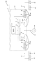
図1で示す電源システム100は、車両に搭載される第1蓄電部91及び第2蓄電部92を備えた車載用の電源システムとして構成されている。リレー装置2は、電源システム100の一部をなしており、第1蓄電部91と第2蓄電部92との間を通電状態と非通電状態とに切り替える機能を有する。 <Example 1>
Embodiment 1 of the present invention will be described below.
Apower supply system 100 shown in FIG. 1 is configured as an in-vehicle power supply system including a first power storage unit 91 and a second power storage unit 92 mounted on a vehicle. Relay device 2 forms part of power supply system 100 and has a function of switching between first power storage unit 91 and second power storage unit 92 between an energized state and a non-energized state.
以下、本発明を具体化した実施例1について説明する。
図1で示す電源システム100は、車両に搭載される第1蓄電部91及び第2蓄電部92を備えた車載用の電源システムとして構成されている。リレー装置2は、電源システム100の一部をなしており、第1蓄電部91と第2蓄電部92との間を通電状態と非通電状態とに切り替える機能を有する。 <Example 1>
A
以下では、車載用電源システム100の例として、主たる負荷である第1の電気負荷81と、補助的な負荷である第2の電気負荷82とを備え、第1の電気負荷81と第2の電気負荷82とが同等の機能を有する構成を代表例として説明する。但し、あくまで代表例であり、リレー装置2の適用対象はこの構成のみに限定されない。
Hereinafter, as an example of the in-vehicle power supply system 100, a first electric load 81 that is a main load and a second electric load 82 that is an auxiliary load are provided, and the first electric load 81 and the second electric load 82 are included. A configuration in which the electrical load 82 has an equivalent function will be described as a representative example. However, this is merely a representative example, and the application target of the relay device 2 is not limited to this configuration.
メイン負荷として機能する第1の電気負荷81は、例えば電動式パワーステアリングシステムであり、第1蓄電部91からの電力供給を受けてモータ等の電気部品が動作する構成をなす。サブ負荷として機能する第2の電気負荷82は、第1の電気負荷81と同等の構成及び機能を有する電動式パワーステアリングシステムである。電源システム100は、第1の電気負荷81に異常が生じた場合に、第1の電気負荷81に代えて第2の電気負荷82を動作させることで、第1の電気負荷81の異常時でも第1の電気負荷81の機能を維持し得るシステムとして構成されている。
The first electric load 81 that functions as the main load is, for example, an electric power steering system, and has a configuration in which an electric component such as a motor operates upon receiving power supply from the first power storage unit 91. The second electric load 82 that functions as a sub load is an electric power steering system having the same configuration and function as the first electric load 81. The power supply system 100 operates the second electric load 82 instead of the first electric load 81 when an abnormality occurs in the first electric load 81, so that even when the first electric load 81 is abnormal. The system is configured as a system capable of maintaining the function of the first electric load 81.
第1蓄電部91は、第1の電気負荷81に電力を供給し得る電源部であり、例えば鉛バッテリなどの公知の電源によって構成されている。
The 1st electrical storage part 91 is a power supply part which can supply electric power to the 1st electric load 81, for example, is comprised by well-known power supplies, such as a lead battery.
第2蓄電部92は、第2の電気負荷82に電力を供給し得る電源部であり、例えばリチウムイオン電池や電気二重層キャパシタなどの公知の電源によって構成されている。本構成では、第2蓄電部92と後述するリレー装置2とを備えた形で車載用電源装置1(以下、単に電源装置1ともいう)が構成されている。この電源装置1は、例えばリレー装置2と第2蓄電部92とが一体的なユニットとして構成されている。リレー装置2と第2蓄電部92とを一体的なユニットとして構成する例は様々であり、リレー装置2と第2蓄電部92とが共通のフレームに対して固定される構成であってもよく、リレー装置2と第2蓄電部92とが共通のケース内に収容される構成であってもよく、リレー装置2の一部をなす基板に第2蓄電部92が実装される構成などであってもよい。
The second power storage unit 92 is a power source unit that can supply power to the second electric load 82, and is configured by a known power source such as a lithium ion battery or an electric double layer capacitor. In this configuration, the in-vehicle power supply device 1 (hereinafter also simply referred to as the power supply device 1) is configured to include the second power storage unit 92 and a relay device 2 described later. In the power supply device 1, for example, the relay device 2 and the second power storage unit 92 are configured as an integral unit. There are various examples in which the relay device 2 and the second power storage unit 92 are configured as an integral unit, and the relay device 2 and the second power storage unit 92 may be fixed to a common frame. The relay device 2 and the second power storage unit 92 may be housed in a common case, or the second power storage unit 92 may be mounted on a substrate that forms part of the relay device 2. May be.
第1蓄電部91及び第1の電気負荷81は、リレー装置2の外部に設けられた配線71に電気的に接続されている。配線71は、例えばワイヤなどによって構成され、後述する第1導電路51に電気的に接続されるとともに第1導電路51を介してリレー部4の一端側に電気的に接続されている。第2蓄電部92及び第2の電気負荷82は、リレー装置2の外部に設けられた配線72に電気的に接続されている。配線72は、例えばワイヤなどによって構成され、後述する第2導電路52に電気的に接続されるとともに第2導電路52を介してリレー部4の他端側に電気的に接続されている。
The first power storage unit 91 and the first electric load 81 are electrically connected to a wiring 71 provided outside the relay device 2. The wiring 71 is made of, for example, a wire or the like, and is electrically connected to a first conductive path 51 (to be described later) and is electrically connected to one end side of the relay unit 4 via the first conductive path 51. The second power storage unit 92 and the second electric load 82 are electrically connected to a wiring 72 provided outside the relay device 2. The wiring 72 is made of, for example, a wire or the like, and is electrically connected to a second conductive path 52 to be described later and electrically connected to the other end side of the relay unit 4 via the second conductive path 52.
発電機95は、公知のオルタネータとして構成されており、所定の時期に動作するとともに配線53に対して発電電圧を印加する構成をなす。発電機95は、減速エネルギー回生制御が可能な構成であり、減速時の回生エネルギーを例えば第1蓄電部91の充電に利用し得る構成をなす。
The generator 95 is configured as a known alternator, and operates at a predetermined time and applies a generated voltage to the wiring 53. The generator 95 is configured to be capable of deceleration energy regeneration control, and is configured to be able to use the regeneration energy at the time of deceleration, for example, for charging the first power storage unit 91.
配線53は、発電機95の発電電力を供給する経路であり、例えばワイヤや配線パターンなどによって構成され、後述する第1スイッチ部11と第2スイッチ部12との間の導電路に電気的に接続されている。なお、図1の例では、配線53の端部から第1蓄電部91側に分岐する導電路が第1導電路51であり、配線53の端部から第2蓄電部92側に分岐する導電路が第2導電路52である。
The wiring 53 is a path for supplying power generated by the generator 95, and is configured by, for example, a wire or a wiring pattern, and is electrically connected to a conductive path between the first switch unit 11 and the second switch unit 12 described later. It is connected. In the example of FIG. 1, the conductive path that branches from the end of the wiring 53 to the first power storage unit 91 side is the first conductive path 51, and the conductive path that branches from the end of the wiring 53 to the second power storage unit 92 side. The path is the second conductive path 52.
リレー装置2は、第1導電路51と、第2導電路52と、リレー部4と、第1電圧検出部21(電圧モニタ)と、第1電流検出部31(電流モニタ)と、第2電圧検出部22(電圧モニタ)と、第2電流検出部32(電流モニタ)と、制御部3とを備える。リレー装置2は、例えば基板本体に各種電子部品が実装されてなる回路基板として構成され、第1導電路51が図示しない端子を介して配線71に接続され、第2導電路52が図示しない端子を介して配線72に接続されている。
The relay device 2 includes a first conductive path 51, a second conductive path 52, a relay unit 4, a first voltage detection unit 21 (voltage monitor), a first current detection unit 31 (current monitor), and a second A voltage detection unit 22 (voltage monitor), a second current detection unit 32 (current monitor), and a control unit 3 are provided. The relay device 2 is configured, for example, as a circuit board in which various electronic components are mounted on a board body, the first conductive path 51 is connected to the wiring 71 via a terminal (not shown), and the second conductive path 52 is a terminal (not shown). It is connected to the wiring 72 via.
第1導電路51は、一端が配線53に接続され、他端が第1蓄電部91側の配線71に接続されており、配線71を介して第1蓄電部91に電気的に接続されている。第1導電路51は、電力線であり、第1スイッチ部11のオン動作時には発電機95からの発電電力に基づいて第1蓄電部91へ供給される充電電流が流れる経路となる。第1導電路51には、後述する第1電圧検出部21及び第1電流検出部31が介在する。
The first conductive path 51 has one end connected to the wiring 53 and the other end connected to the wiring 71 on the first power storage unit 91 side, and is electrically connected to the first power storage unit 91 via the wiring 71. Yes. The first conductive path 51 is a power line, and becomes a path through which a charging current supplied to the first power storage unit 91 flows based on the generated power from the generator 95 when the first switch unit 11 is turned on. A first voltage detection unit 21 and a first current detection unit 31 described later are interposed in the first conductive path 51.
第2導電路52は、第2蓄電部92側の配線72に接続されており、配線72を介して第2蓄電部92に電気的に接続されている。第2導電路52は、電力線であり、第2スイッチ部12のオン動作時には発電機95からの発電電力に基づいて第2蓄電部92へ供給される充電電流が流れる経路となる。第2導電路52には、後述する第2電圧検出部22及び第2電流検出部32が介在する。
The second conductive path 52 is connected to the wiring 72 on the second power storage unit 92 side, and is electrically connected to the second power storage unit 92 via the wiring 72. The second conductive path 52 is a power line and serves as a path through which a charging current supplied to the second power storage unit 92 flows based on the generated power from the generator 95 when the second switch unit 12 is turned on. A second voltage detector 22 and a second current detector 32 described later are interposed in the second conductive path 52.
リレー部4は、第1スイッチ部11と第2スイッチ部12とバイパス部5とを備える。第1スイッチ部11は、例えば1又は複数の公知の半導体スイッチ素子などによって構成され、発電機95と第1蓄電部91との間の経路となる第1導電路51を通電許容状態と通電遮断状態とに切り替える機能を有する。第2スイッチ部12は、例えば1又は複数の公知の半導体スイッチ素子などによって構成され、発電機95と第2蓄電部92との間の経路となる第2導電路52を通電許容状態と通電遮断状態とに切り替える機能を有する。バイパス部5は、抵抗部7と第3スイッチ部13とが直列に接続された直列回路6を有する。直列回路6の一端は、第1導電路51における第1スイッチ部11と第1蓄電部91との間の接続部51Aに電気的に接続され、直列回路6の他端が第2導電路52における第2スイッチ部12と第2蓄電部92との間の接続部52Aに電気的に接続されている。
The relay unit 4 includes a first switch unit 11, a second switch unit 12, and a bypass unit 5. The first switch unit 11 is configured by, for example, one or a plurality of known semiconductor switch elements, and the first conductive path 51 serving as a path between the generator 95 and the first power storage unit 91 is allowed to be energized and interrupted. It has a function to switch to a state. The second switch unit 12 is configured by, for example, one or a plurality of known semiconductor switch elements, and the second conductive path 52 serving as a path between the generator 95 and the second power storage unit 92 is allowed to be energized and interrupted. It has a function to switch to a state. The bypass unit 5 includes a series circuit 6 in which a resistor unit 7 and a third switch unit 13 are connected in series. One end of the series circuit 6 is electrically connected to a connection portion 51A between the first switch unit 11 and the first power storage unit 91 in the first conductive path 51, and the other end of the series circuit 6 is the second conductive path 52. Are electrically connected to a connecting portion 52A between the second switch portion 12 and the second power storage portion 92.
リレー部4は、第1スイッチ部11がオン状態であるときには、第1スイッチ部11が導通し、発電機95から第1スイッチ部11を介して第1蓄電部91に充電電流を供給することが可能となる。第1スイッチ部11がオフ状態であるときには、第1スイッチ部11は発電機95側から第1スイッチ部11を介して第1蓄電部91側に電流を流すことを遮断する遮断状態となる。
When the first switch unit 11 is on, the relay unit 4 conducts the first switch unit 11 and supplies a charging current from the generator 95 to the first power storage unit 91 via the first switch unit 11. Is possible. When the 1st switch part 11 is an OFF state, the 1st switch part 11 will be in the interruption | blocking state which interrupts | blocks flowing an electric current from the generator 95 side via the 1st switch part 11 to the 1st electrical storage part 91 side.
同様に、第2スイッチ部12がオン状態であるときには、第2スイッチ部12が導通し、発電機95から第2スイッチ部12を介して第2蓄電部92に充電電流を供給することが可能となる。第2スイッチ部12がオフ状態であるときには、第2スイッチ部12は発電機95側から第2スイッチ部12を介して第2蓄電部92側に電流を流すことを遮断する遮断状態となる。
Similarly, when the second switch unit 12 is in the ON state, the second switch unit 12 becomes conductive, and a charging current can be supplied from the generator 95 to the second power storage unit 92 via the second switch unit 12. It becomes. When the second switch unit 12 is in the off state, the second switch unit 12 is in a cut-off state that blocks the flow of current from the generator 95 side to the second power storage unit 92 side via the second switch unit 12.
直列回路6は、第3スイッチ部13がオン状態であるときに、第3スイッチ部13が導通し、バイパス部5に電流が流れる状態となる。第3スイッチ部13がオフ状態であるときには、第3スイッチ部13が非導通状態となり、バイパス部5に電流が流れない状態となる。
In the series circuit 6, when the third switch unit 13 is in the on state, the third switch unit 13 becomes conductive and a current flows through the bypass unit 5. When the third switch unit 13 is in the off state, the third switch unit 13 is in a non-conducting state and no current flows through the bypass unit 5.
このような機能を有する第1スイッチ部11、第2スイッチ部12、第3スイッチ部13の例としては、図2のような例が挙げられる。図2の例では、第1スイッチ部11は、互いに異なる向きで直列に接続された2つのMOSFET11A,11Bによって構成されている。第2スイッチ部12は、互いに異なる向きで直列に接続された2つのMOSFET12A,12Bによって構成されている。第3スイッチ部13は、互いに異なる向きで直列に接続された2つのMOSFET13A,13Bによって構成されている。第1スイッチ部11を構成するMOSFET11A,11B、第2スイッチ部12を構成するMOSFET12A,12B、第3スイッチ部13を構成するMOSFET13A,13Bのいずれも、所謂突き合わせ状態(ボディーダイオードを互いに逆向きとする配置状態)で直列に設けられているため、いずれのスイッチ部も、2つのMOSFETがオフ状態のときには双方向の通電を遮断する状態となる。
Examples of the first switch unit 11, the second switch unit 12, and the third switch unit 13 having such a function include an example as shown in FIG. In the example of FIG. 2, the first switch unit 11 is configured by two MOSFETs 11A and 11B connected in series in different directions. The second switch unit 12 is composed of two MOSFETs 12A and 12B connected in series in different directions. The third switch unit 13 is composed of two MOSFETs 13A and 13B connected in series in different directions. All of the MOSFETs 11A and 11B constituting the first switch unit 11, the MOSFETs 12A and 12B constituting the second switch unit 12, and the MOSFETs 13A and 13B constituting the third switch unit 13 are in a so-called butted state (the body diodes are opposite to each other). Since the two MOSFETs are in the off state, both switch parts are in a state of interrupting bidirectional energization.
図1等で示す第1電圧検出部21は、公知の電圧検出回路(電圧モニタ)として構成され、第1導電路51の電圧を検出する機能を有する。第1電圧検出部21で検出された電圧値は、信号線によって制御部3に入力される。
1 is configured as a known voltage detection circuit (voltage monitor) and has a function of detecting the voltage of the first conductive path 51. The voltage value detected by the first voltage detection unit 21 is input to the control unit 3 through a signal line.
第2電圧検出部22は、公知の電圧検出回路(電圧モニタ)として構成され、第2導電路52の電圧を検出する機能を有する。第2電圧検出部22で検出された電圧値は、信号線によって制御部3に入力される。
The second voltage detection unit 22 is configured as a known voltage detection circuit (voltage monitor) and has a function of detecting the voltage of the second conductive path 52. The voltage value detected by the second voltage detection unit 22 is input to the control unit 3 through a signal line.
第1電流検出部31は、公知の電流検出回路(電流モニタ)として構成され、第1導電路51を流れる電流を検出する機能を有する。第1電流検出部31で検出された電流値は、信号線によって制御部3に入力される。
The first current detection unit 31 is configured as a known current detection circuit (current monitor), and has a function of detecting a current flowing through the first conductive path 51. The current value detected by the first current detection unit 31 is input to the control unit 3 through a signal line.
第2電流検出部32は、公知の電流検出回路(電流モニタ)として構成され、第2導電路52を流れる電流を検出する機能を有する。第2電流検出部32で検出された電流値は、信号線によって制御部3に入力される。
The second current detection unit 32 is configured as a known current detection circuit (current monitor) and has a function of detecting a current flowing through the second conductive path 52. The current value detected by the second current detection unit 32 is input to the control unit 3 through a signal line.
制御部3は、例えば、CPU、ROM、RAM、A/D変換器などを備えたマイクロコンピュータを有してなる。制御部3には、第1電圧検出部21の検出値(第1導電路51の電圧値)、第2電圧検出部22の検出値(第2導電路52の電圧値)、第1電流検出部31の検出値(第1導電路51の電流値)、第2電流検出部32の検出値(第2導電路52の電流値)が入力される。制御部3に入力された各検出値は、制御部3内のA/D変換器にてデジタル値に変換される。
The control unit 3 includes, for example, a microcomputer provided with a CPU, ROM, RAM, A / D converter, and the like. The control unit 3 includes a detection value of the first voltage detection unit 21 (voltage value of the first conductive path 51), a detection value of the second voltage detection unit 22 (voltage value of the second conductive path 52), and a first current detection. The detection value of the unit 31 (current value of the first conductive path 51) and the detection value of the second current detection unit 32 (current value of the second conductive path 52) are input. Each detection value input to the control unit 3 is converted into a digital value by an A / D converter in the control unit 3.
ここで、通常時におけるリレー装置2の基本動作を説明する。
図1等で示すリレー装置2では、制御部3によって第1スイッチ部11、第2スイッチ部12、及び第3スイッチ部13のオンオフが制御される。 Here, the basic operation of therelay device 2 during normal operation will be described.
In therelay device 2 shown in FIG. 1 and the like, the control unit 3 controls the on / off of the first switch unit 11, the second switch unit 12, and the third switch unit 13.
図1等で示すリレー装置2では、制御部3によって第1スイッチ部11、第2スイッチ部12、及び第3スイッチ部13のオンオフが制御される。 Here, the basic operation of the
In the
リレー装置2では、所定の第1条件の成立時に第1スイッチ部11をオン動作させ、第1蓄電部91を充電する。制御部3が第1スイッチ部11をオン状態に制御するタイミングは特に限定されず、条件数も1つに限定されない。例えば、制御部3は、第1蓄電部91の出力電圧を継続的に監視し、第1蓄電部91の出力電圧が所定の第1閾値未満に低下した場合に第1スイッチ部11をオン状態に制御してもよい。また、制御部3は、発電機95が車両減速時の回生発電を行う時期などの回生制御時に、常に又は所定条件(例えば、第1蓄電部91の出力電圧が所定値未満である場合など)が成立しているときに第1スイッチ部11をオン状態に制御してもよい。勿論、第1スイッチ部11をオン状態に制御する時期はこれら以外の時期であってもよい。
The relay device 2 turns on the first switch unit 11 to charge the first power storage unit 91 when a predetermined first condition is established. The timing at which the control unit 3 controls the first switch unit 11 to the on state is not particularly limited, and the number of conditions is not limited to one. For example, the control unit 3 continuously monitors the output voltage of the first power storage unit 91 and turns on the first switch unit 11 when the output voltage of the first power storage unit 91 drops below a predetermined first threshold value. You may control to. In addition, the control unit 3 always or at a predetermined condition (for example, when the output voltage of the first power storage unit 91 is less than a predetermined value) during regenerative control such as when the generator 95 performs regenerative power generation when the vehicle decelerates. When the above is established, the first switch unit 11 may be controlled to be in an on state. Of course, the time for controlling the first switch unit 11 to be in the ON state may be other time.
制御部3は、少なくとも第1スイッチ部11のオン動作時に第2スイッチ部12をオフ動作させる。つまり、第1スイッチ部11と第2スイッチ部12とが同時にオン動作しないように制御する。これにより、第1導電路51と第2導電路52からなる導電路50が接続部51Aと接続部52Aの間で導通することがなくなり、第1蓄電部91と第2蓄電部92との間で導電路50のみを介した通電がなされないようになる。つまり、バイパス部5を介さない限り第1蓄電部91と第2蓄電部92との間で電流が流れないようになる。
The control unit 3 turns off the second switch unit 12 at least when the first switch unit 11 is turned on. That is, the first switch unit 11 and the second switch unit 12 are controlled so as not to be turned on simultaneously. As a result, the conductive path 50 including the first conductive path 51 and the second conductive path 52 is not electrically connected between the connection part 51A and the connection part 52A, and the first power storage part 91 and the second power storage part 92 are not connected. Thus, power is not supplied only through the conductive path 50. That is, current does not flow between the first power storage unit 91 and the second power storage unit 92 unless the bypass unit 5 is interposed.
制御部3は、第1スイッチ部11をオン動作させる時期に、常に、又は所定条件時(例えば、第2蓄電部92の出力電圧が所定値未満の場合など)に第3スイッチ部13をオン動作させる。第1スイッチ部11のオン動作時に第2スイッチ部12をオフ動作させ且つ第3スイッチ部13をオン動作させると、発電機95の発電時に、第1蓄電部91に対しては図3で概念的に示すように発電機95からの充電電流を抵抗値の低い第1スイッチ部11を介して効率よく供給することができるとともに第2蓄電部92に対してはバイパス部5を介してこれよりも相対的に小さい充電電流を供給することができる。
The control unit 3 turns on the third switch unit 13 at a time when the first switch unit 11 is turned on, or at a predetermined condition (for example, when the output voltage of the second power storage unit 92 is less than a predetermined value). Make it work. When the second switch unit 12 is turned off and the third switch unit 13 is turned on when the first switch unit 11 is turned on, the first power storage unit 91 is conceptually shown in FIG. As shown, the charging current from the generator 95 can be efficiently supplied through the first switch unit 11 having a low resistance value, and the second power storage unit 92 can be supplied through the bypass unit 5. Also, a relatively small charging current can be supplied.
リレー装置2では、所定の第2条件の成立時に第2スイッチ部12をオン動作させ、第2蓄電部92を充電する。制御部3が第2スイッチ部12をオン状態に制御するタイミングは特に限定されず、条件数も1つに限定されない。例えば、制御部3は、第2蓄電部92の出力電圧を継続的に監視し、第2蓄電部92の出力電圧が所定の第2閾値未満に低下した場合であって且つ第1スイッチ部11をオン動作させないときに第2スイッチ部12をオン状態に制御してもよい。或いは、制御部3は、発電機95が車両減速時の回生発電を行う時期であって且つ第1スイッチ部11をオン動作させない時期に、常に又は所定条件(例えば、第2蓄電部92の出力電圧が所定値未満である場合など)が成立しているときに第2スイッチ部12をオン状態に制御してもよい。勿論、第2スイッチ部12をオン状態に制御する時期はこれら以外の時期であってもよい。
The relay device 2 turns on the second switch unit 12 to charge the second power storage unit 92 when a predetermined second condition is satisfied. The timing at which the control unit 3 controls the second switch unit 12 to the on state is not particularly limited, and the number of conditions is not limited to one. For example, the control unit 3 continuously monitors the output voltage of the second power storage unit 92, the output voltage of the second power storage unit 92 falls below a predetermined second threshold, and the first switch unit 11. The second switch unit 12 may be controlled to be in an on state when the switch is not turned on. Alternatively, the control unit 3 always or at a time when the generator 95 performs regenerative power generation when the vehicle decelerates and does not turn on the first switch unit 11 (for example, the output of the second power storage unit 92). The second switch unit 12 may be controlled to be turned on when the voltage is less than a predetermined value. Of course, the time when the second switch unit 12 is controlled to be in the ON state may be other time.
制御部3は、少なくとも第2スイッチ部12のオン動作時に第1スイッチ部11をオフ動作させる。この場合も、第1スイッチ部11と第2スイッチ部12とが同時にオン動作しないように制御する。そして、制御部3は、第2スイッチ部12をオン動作させる時期に、常に、又は所定条件時(例えば、第1蓄電部91の出力電圧が所定値未満の場合など)に第3スイッチ部13をオン動作させる。第2スイッチ部12のオン動作時に第1スイッチ部11をオフ動作させ且つ第3スイッチ部13をオン動作させると、発電機95の発電時に、第2蓄電部92に対しては発電機95からの充電電流を抵抗値の低い第2スイッチ部12を介して効率よく供給することができるとともに第1蓄電部91に対してはバイパス部5を介してこれよりも相対的に小さい充電電流を供給することができる。
The control unit 3 turns off the first switch unit 11 at least when the second switch unit 12 is turned on. Also in this case, the first switch unit 11 and the second switch unit 12 are controlled so as not to be turned on simultaneously. Then, the control unit 3 always turns the second switch unit 12 on, or at a predetermined condition (for example, when the output voltage of the first power storage unit 91 is less than a predetermined value), the third switch unit 13. To turn on. When the first switch unit 11 is turned off and the third switch unit 13 is turned on when the second switch unit 12 is turned on, the second power storage unit 92 is turned off from the generator 95 when the generator 95 generates power. Can be efficiently supplied through the second switch unit 12 having a low resistance value, and a relatively smaller charging current can be supplied to the first power storage unit 91 through the bypass unit 5. can do.
このように、制御部3は、少なくとも第1スイッチ部11のオン動作時に第2スイッチ部12をオフ動作させ且つ第3スイッチをオン動作させる第1制御と、少なくとも第2スイッチ部12のオン動作時に第1スイッチ部11をオフ動作させ且つ第3スイッチ部13をオン動作させる第2制御とを行い得るようになっている。
As described above, the control unit 3 performs the first control to turn off the second switch unit 12 and turn on the third switch at least when the first switch unit 11 is turned on, and to turn on the second switch unit 12 at least. Sometimes, the second control for turning off the first switch unit 11 and turning on the third switch unit 13 can be performed.
次に、異常時におけるリレー装置2の動作を説明する。
制御部3は、所定の異常状態が発生した場合、リレー部4に設けられた第1スイッチ部11、第2スイッチ部12、第3スイッチ部13を強制的にオフ状態に制御する。つまり、所定の異常状態の発生前からオフ状態であるスイッチ部についてはそのままオフ状態を維持し、所定の異常状態の発生前にオン状態であるスイッチ部については即座にオフ状態に切り替える。具体的には、制御部3は、第1電圧検出部21及び第2電圧検出部22から入力される各検出値(各電圧値)を継続的に監視し、第1電圧検出部21及び第2電圧検出部22の少なくともいずれかから入力される検出値が所定の異常閾値Vth以下となった場合に第1スイッチ部11、第2スイッチ部12、第3スイッチ部13を全てオフ状態にする。なお、異常閾値Vthの値は特に限定されないが、例えば上述の第1閾値や第2閾値よりも低い値に設定することができる。 Next, the operation of therelay device 2 at the time of abnormality will be described.
When a predetermined abnormal state occurs, thecontrol unit 3 forcibly controls the first switch unit 11, the second switch unit 12, and the third switch unit 13 provided in the relay unit 4 to be turned off. That is, the switch unit that is in the off state before the occurrence of the predetermined abnormal state is maintained in the off state as it is, and the switch unit that is in the on state before the occurrence of the predetermined abnormal state is immediately switched to the off state. Specifically, the control unit 3 continuously monitors each detection value (each voltage value) input from the first voltage detection unit 21 and the second voltage detection unit 22, and the first voltage detection unit 21 and the first voltage detection unit 21 The first switch unit 11, the second switch unit 12, and the third switch unit 13 are all turned off when a detection value input from at least one of the two voltage detection units 22 is equal to or lower than a predetermined abnormality threshold Vth. . The value of the abnormal threshold value Vth is not particularly limited, but can be set to a value lower than, for example, the first threshold value or the second threshold value described above.
制御部3は、所定の異常状態が発生した場合、リレー部4に設けられた第1スイッチ部11、第2スイッチ部12、第3スイッチ部13を強制的にオフ状態に制御する。つまり、所定の異常状態の発生前からオフ状態であるスイッチ部についてはそのままオフ状態を維持し、所定の異常状態の発生前にオン状態であるスイッチ部については即座にオフ状態に切り替える。具体的には、制御部3は、第1電圧検出部21及び第2電圧検出部22から入力される各検出値(各電圧値)を継続的に監視し、第1電圧検出部21及び第2電圧検出部22の少なくともいずれかから入力される検出値が所定の異常閾値Vth以下となった場合に第1スイッチ部11、第2スイッチ部12、第3スイッチ部13を全てオフ状態にする。なお、異常閾値Vthの値は特に限定されないが、例えば上述の第1閾値や第2閾値よりも低い値に設定することができる。 Next, the operation of the
When a predetermined abnormal state occurs, the
ここで、異常発生時の動作の例を説明する。
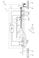
まず、上述した第1制御時に異常が発生した場合について説明する。リレー部4において第1スイッチ部11及び第3スイッチ部13がオン状態であり且つ第2スイッチ部12がオフ状態であり、発電機95が発電動作を行っているときに図4のように第1蓄電部91に接続された配線71において地絡が発生すると、配線71及び第1導電路51の電圧値が瞬時に0V(グランド電位)近くに変化し、図4のように地絡発生部分に向けて電流が流れ込む。但し、バイパス部5には抵抗部7が設けられているため、第2蓄電部92側から地絡発生部分に向けて流れる電流は抵抗部7を介して流れ込むことになる。つまり、このような地絡発生時には、抵抗部7の抵抗成分により、抵抗部7を挟んで地絡発生側とは反対側に配置された導電路(即ち第2導電路52)の電圧は0V付近まで低下せずに大幅に抑えられる。また、図4のような地絡が発生した場合、地絡発生直後に第1電圧検出部21で検出される電圧値が瞬時に異常閾値Vth未満となるため、制御部3は、地絡発生直後に瞬時に異常と判定することができる。そして、制御部3は、全ての第1スイッチ部11、第2スイッチ部12、第3スイッチ部13をオフ状態とする制御を即座に行い、第1導電路51と第2導電路52の間の通電を迅速に遮断することができる。 Here, an example of an operation when an abnormality occurs will be described.
First, a case where an abnormality has occurred during the first control described above will be described. In therelay unit 4, when the first switch unit 11 and the third switch unit 13 are in the on state and the second switch unit 12 is in the off state, and the generator 95 is performing the power generation operation, When a ground fault occurs in the wiring 71 connected to one power storage unit 91, the voltage values of the wiring 71 and the first conductive path 51 instantaneously change to near 0 V (ground potential), and a ground fault occurrence portion as shown in FIG. Current flows into However, since the resistance unit 7 is provided in the bypass unit 5, a current that flows from the second power storage unit 92 side toward the ground fault occurrence part flows through the resistance unit 7. That is, when such a ground fault occurs, the voltage of the conductive path (that is, the second conductive path 52) arranged on the opposite side of the ground fault generation side across the resistance section 7 is 0 V due to the resistance component of the resistance section 7. It is greatly suppressed without deteriorating to the vicinity. Further, when a ground fault as shown in FIG. 4 occurs, the voltage value detected by the first voltage detection unit 21 immediately after the occurrence of the ground fault instantaneously becomes less than the abnormal threshold Vth. Immediately thereafter, it can be determined that there is an abnormality instantaneously. Then, the control unit 3 immediately performs control to turn off all of the first switch unit 11, the second switch unit 12, and the third switch unit 13, and between the first conductive path 51 and the second conductive path 52. Can be cut off quickly.
まず、上述した第1制御時に異常が発生した場合について説明する。リレー部4において第1スイッチ部11及び第3スイッチ部13がオン状態であり且つ第2スイッチ部12がオフ状態であり、発電機95が発電動作を行っているときに図4のように第1蓄電部91に接続された配線71において地絡が発生すると、配線71及び第1導電路51の電圧値が瞬時に0V(グランド電位)近くに変化し、図4のように地絡発生部分に向けて電流が流れ込む。但し、バイパス部5には抵抗部7が設けられているため、第2蓄電部92側から地絡発生部分に向けて流れる電流は抵抗部7を介して流れ込むことになる。つまり、このような地絡発生時には、抵抗部7の抵抗成分により、抵抗部7を挟んで地絡発生側とは反対側に配置された導電路(即ち第2導電路52)の電圧は0V付近まで低下せずに大幅に抑えられる。また、図4のような地絡が発生した場合、地絡発生直後に第1電圧検出部21で検出される電圧値が瞬時に異常閾値Vth未満となるため、制御部3は、地絡発生直後に瞬時に異常と判定することができる。そして、制御部3は、全ての第1スイッチ部11、第2スイッチ部12、第3スイッチ部13をオフ状態とする制御を即座に行い、第1導電路51と第2導電路52の間の通電を迅速に遮断することができる。 Here, an example of an operation when an abnormality occurs will be described.
First, a case where an abnormality has occurred during the first control described above will be described. In the
このように、第1制御の実行時(即ち、第2スイッチ部12をオフ状態で維持しつつ第1スイッチ部11及び第3スイッチ部13をオン動作させて両蓄電部に対して充電電流を供給しているとき)に第1導電路51側で地絡が発生した場合、バイパス部5に存在する抵抗部7の抵抗成分によって第2導電路52側の電圧低下を抑えることができ、このように電圧低下を抑制しながら迅速に全てのスイッチ部を遮断状態とすることができるため、第2導電路52に接続された負荷への供給電圧が必要電圧以下に低下する可能性をより低くすることができる。
As described above, when the first control is executed (that is, the first switch unit 11 and the third switch unit 13 are turned on while maintaining the second switch unit 12 in the OFF state), the charging current is supplied to both power storage units. When a ground fault occurs on the first conductive path 51 side during the supply), the voltage drop on the second conductive path 52 side can be suppressed by the resistance component of the resistance section 7 present in the bypass section 5. Thus, since it is possible to quickly turn off all the switch parts while suppressing the voltage drop, the possibility that the supply voltage to the load connected to the second conductive path 52 will drop below the required voltage is lower. can do.
このような作用及び効果は、第1制御時に第2蓄電部92側で地絡が発生した場合でも同様である。即ち、第2スイッチ部12をオフ状態で維持しつつ第1スイッチ部11及び第3スイッチ部13をオン動作させて両蓄電部に対して充電電流を供給しているときに第2導電路52側で地絡が発生した場合、バイパス部5に存在する抵抗部7の抵抗成分によって第1導電路51側の電圧低下を抑えることができ、このように電圧低下を抑制しながら迅速に全てのスイッチ部を遮断状態とすることができるため、第1導電路51に接続された負荷への供給電圧が必要電圧以下に低下する可能性をより低くすることができる。
Such operations and effects are the same even when a ground fault occurs on the second power storage unit 92 side during the first control. That is, when the first switch unit 11 and the third switch unit 13 are turned on while the second switch unit 12 is maintained in the off state and the charging current is supplied to both power storage units, the second conductive path 52 is provided. When a ground fault occurs on the side, the voltage drop on the first conductive path 51 side can be suppressed by the resistance component of the resistance unit 7 present in the bypass unit 5, and thus all the voltages can be quickly reduced while suppressing the voltage drop. Since the switch unit can be in the cut-off state, the possibility that the supply voltage to the load connected to the first conductive path 51 is lowered below the required voltage can be further reduced.
次に、上述した第2制御時に異常が発生した場合について説明する。リレー部4において第2スイッチ部12及び第3スイッチ部13がオン状態であり且つ第1スイッチ部11がオフ状態であり、発電機95が発電動作を行っているときに図5のように第2蓄電部92に接続された配線72において地絡が発生すると、配線72及び第2導電路52の電圧値が瞬時に0V(グランド電位)近くに変化し、図5のように地絡発生部分に向けて電流が流れ込む。但し、バイパス部5には抵抗部7が設けられているため、第1蓄電部91側から地絡発生部分に向けて流れる電流は抵抗部7を介して流れ込むことになる。つまり、このような地絡発生時には、抵抗部7の抵抗成分により、抵抗部7を挟んで地絡発生側とは反対側に配置された導電路(即ち第1導電路51)の電圧は0V付近まで低下せずに大幅に抑えられる。また、図5のような地絡が発生した場合、地絡発生直後に第2電圧検出部22で検出される電圧値が瞬時に異常閾値Vth未満となるため、制御部3は、地絡発生直後に瞬時に異常と判定することができる。そして、制御部3は、全ての第1スイッチ部11、第2スイッチ部12、第3スイッチ部13をオフ状態とする制御を即座に行い、第1導電路51と第2導電路52の間の通電を迅速に遮断することができる。
Next, a case where an abnormality has occurred during the second control described above will be described. In the relay unit 4, when the second switch unit 12 and the third switch unit 13 are in the on state and the first switch unit 11 is in the off state, and the generator 95 is performing the power generation operation, 2 When a ground fault occurs in the wiring 72 connected to the power storage unit 92, the voltage values of the wiring 72 and the second conductive path 52 instantaneously change to near 0 V (ground potential), and a ground fault occurrence portion is obtained as shown in FIG. Current flows into However, since the resistance unit 7 is provided in the bypass unit 5, the current that flows from the first power storage unit 91 side toward the ground fault occurrence part flows through the resistance unit 7. That is, when such a ground fault occurs, the voltage of the conductive path (that is, the first conductive path 51) arranged on the opposite side of the ground fault generation side across the resistance section 7 is 0 V due to the resistance component of the resistance section 7. It is greatly suppressed without deteriorating to the vicinity. When a ground fault as shown in FIG. 5 occurs, the voltage value detected by the second voltage detection unit 22 immediately after the occurrence of the ground fault instantaneously becomes less than the abnormal threshold Vth. Immediately thereafter, it can be determined that there is an abnormality instantaneously. Then, the control unit 3 immediately performs control to turn off all of the first switch unit 11, the second switch unit 12, and the third switch unit 13, and between the first conductive path 51 and the second conductive path 52. Can be cut off quickly.
このように、第2制御の実行時(即ち、第1スイッチ部11をオフ状態で維持しつつ第2スイッチ部12及び第3スイッチ部13をオン動作させて両蓄電部に対して充電電流を供給しているとき)に第2導電路52側で地絡が発生した場合、バイパス部5に存在する抵抗部7の抵抗成分によって第1導電路51側の電圧低下を抑えることができ、このように電圧低下を抑制しながら迅速に全てのスイッチ部を遮断状態とすることができるため、第1導電路51に接続された負荷への供給電圧が必要電圧以下に低下する可能性をより低くすることができる。
As described above, when the second control is performed (that is, the second switch unit 12 and the third switch unit 13 are turned on while maintaining the first switch unit 11 in the off state), the charging current is supplied to both power storage units. When a ground fault occurs on the second conductive path 52 side during supply), the voltage drop on the first conductive path 51 side can be suppressed by the resistance component of the resistance section 7 present in the bypass section 5. Thus, it is possible to quickly turn off all the switch sections while suppressing the voltage drop, and therefore, the possibility that the supply voltage to the load connected to the first conductive path 51 will drop below the required voltage is lower. can do.
このような作用及び効果は、第2制御時に第1蓄電部91側で地絡が発生した場合でも同様である。即ち、第1スイッチ部11をオフ状態で維持しつつ第2スイッチ部12及び第3スイッチ部13をオン動作させて両蓄電部に対して充電電流を供給しているときに第1導電路51側で地絡が発生した場合、バイパス部5に存在する抵抗部7の抵抗成分によって第2導電路52側の電圧低下を抑えることができ、このように電圧低下を抑制しながら迅速に全てのスイッチ部を遮断状態とすることができるため、第2導電路52に接続された負荷への供給電圧が必要電圧以下に低下する可能性をより低くすることができる。
Such operations and effects are the same even when a ground fault occurs on the first power storage unit 91 side during the second control. That is, when the second switch unit 12 and the third switch unit 13 are turned on while the first switch unit 11 is maintained in the off state and the charging current is supplied to both power storage units, the first conductive path 51 is provided. When a ground fault occurs on the side, the voltage drop on the second conductive path 52 side can be suppressed by the resistance component of the resistance unit 7 present in the bypass unit 5, and thus all the voltages can be quickly reduced while suppressing the voltage drop. Since the switch portion can be cut off, it is possible to further reduce the possibility that the supply voltage to the load connected to the second conductive path 52 will drop below the required voltage.
なお、異常発生時の動作についての上述した具体例は、充電制御中に第1電圧検出部21又は第2電圧検出部22の検出値が異常範囲となった場合に制御部3が第1スイッチ部11、第2スイッチ部12、第3スイッチ部13を全てオフ状態とする例であったが、この例に限定されない。上述した制御に加えて、また上述した制御に代えて、充電制御中に第1電流検出部31又は第2電流検出部32の検出値が異常範囲となった場合(例えば、所定の過電流閾値よりも大きくなった場合)に制御部3が第1スイッチ部11、第2スイッチ部12、第3スイッチ部13を全てオフ状態とする制御を行ってもよい。
The above-described specific example of the operation at the time of occurrence of an abnormality is the case where the control unit 3 switches the first switch when the detection value of the first voltage detection unit 21 or the second voltage detection unit 22 becomes an abnormal range during the charge control. Although the unit 11, the second switch unit 12, and the third switch unit 13 are all turned off, the present invention is not limited to this example. In addition to the control described above, and in place of the control described above, when the detection value of the first current detection unit 31 or the second current detection unit 32 is in an abnormal range during the charge control (for example, a predetermined overcurrent threshold value) The control unit 3 may perform control to turn off all of the first switch unit 11, the second switch unit 12, and the third switch unit 13).
本構成では、第1電圧検出部21、第2電圧検出部22、第1電流検出部31、第2電流検出部32が検出部の一例に相当し、第1導電路51及び第2導電路52の少なくともいずれかにおける、電流又は電圧の少なくともいずれかを検出する機能を有する。そして、制御部3が第1スイッチ部11、第2スイッチ部12、第3スイッチ部13を切り替える機能を有し、具体的には、第1スイッチ部11、第2スイッチ部12、第3スイッチ部13の少なくともいずれかがオン状態であるときに検出部の検出値が地絡状態に対応した所定の異常範囲内である場合に第1スイッチ部11、第2スイッチ部12、第3スイッチ部13を全てオフ状態とする制御を行う。
In this configuration, the first voltage detection unit 21, the second voltage detection unit 22, the first current detection unit 31, and the second current detection unit 32 correspond to an example of the detection unit, and the first conductive path 51 and the second conductive path. 52 has a function of detecting at least one of a current and a voltage in at least one of 52. And the control part 3 has a function which switches the 1st switch part 11, the 2nd switch part 12, and the 3rd switch part 13, and, specifically, the 1st switch part 11, the 2nd switch part 12, the 3rd switch The first switch unit 11, the second switch unit 12, and the third switch unit when the detection value of the detection unit is within a predetermined abnormal range corresponding to the ground fault state when at least one of the units 13 is in the on state. Control is performed to turn off all of 13.
以上のように、本構成のリレー装置2及び電源装置1は、第1スイッチ部11をオン動作させ第2スイッチ部12をオフ動作させることで、発電機95の発電電力に基づく充電電流を第1蓄電部91に効率的に供給することができる。このときに第1蓄電部91側で地絡が発生した場合、第3スイッチ部13がオフ状態であれば地絡発生部分と第2蓄電部92側の導電路とが絶縁状態となるため第2蓄電部92側の導電路の電圧低下を防ぐことができる。また、第3スイッチ部13がオン状態であっても、地絡発生部分と第2蓄電部92側の導電路との間には抵抗部7が介在することになるため、抵抗部7の抵抗成分により第2蓄電部92側の導電路の電圧低下を抑えることができる。第1スイッチ部11のオン動作時に第2蓄電部92側で地絡が発生した場合も同様であり、第3スイッチ部13がオフ状態であれば地絡発生部分と第1蓄電部91側の導電路とが絶縁状態であるため第1蓄電部91側の導電路の電圧低下を防ぐことができる。また、第3スイッチ部13がオン状態であっても、地絡発生部分と第1蓄電部91側の導電路との間には抵抗部7が介在することになるため、第1蓄電部91側の電圧低下を抑えることができる。
As described above, the relay device 2 and the power supply device 1 configured as described above turn on the first switch unit 11 and turn off the second switch unit 12, so that the charging current based on the generated power of the generator 95 is changed to the first. 1 can be efficiently supplied to the power storage unit 91. If a ground fault occurs on the first power storage unit 91 side at this time, if the third switch unit 13 is in an off state, the ground fault generation part and the conductive path on the second power storage unit 92 side are in an insulated state, so 2 A voltage drop in the conductive path on the power storage unit 92 side can be prevented. Even if the third switch unit 13 is in the ON state, the resistance unit 7 is interposed between the ground fault occurrence part and the conductive path on the second power storage unit 92 side. The voltage drop of the conductive path on the second power storage unit 92 side can be suppressed by the component. The same applies when a ground fault occurs on the second power storage unit 92 side when the first switch unit 11 is on. If the third switch unit 13 is off, the ground fault occurrence part and the first power storage unit 91 side Since the conductive path is in an insulated state, a voltage drop in the conductive path on the first power storage unit 91 side can be prevented. Even if the third switch unit 13 is in the ON state, the resistance unit 7 is interposed between the ground fault occurrence part and the conductive path on the first power storage unit 91 side. Side voltage drop can be suppressed.
同様に、リレー装置2は、第2スイッチ部12をオン動作させ第1スイッチ部11をオフ動作させることで、発電機95の発電電力に基づく充電電流を第2蓄電部92に効率的に供給することができる。このときに第1蓄電部91側で地絡が発生した場合、第3スイッチ部13がオフ状態であれば地絡発生部分と第2蓄電部92側の導電路とが絶縁状態となるため第2蓄電部92側の導電路の電圧低下を防ぐことができる。また、第3スイッチ部13がオン状態であっても、地絡発生部分と第2蓄電部92側の導電路との間には抵抗部7が介在することになるため、抵抗部7の抵抗成分により第2蓄電部92側の導電路の電圧低下を抑えることができる。第2スイッチ部12のオン動作時に第2蓄電部92側で地絡が発生した場合も同様であり、第3スイッチ部13がオフ状態であれば地絡発生部分と第1蓄電部91側の導電路とが絶縁状態であるため第1蓄電部91側の導電路の電圧低下を防ぐことができる。また、第3スイッチ部13がオン状態であっても、地絡発生部分と第1蓄電部91側の導電路との間には抵抗部7が介在することになるため、第1蓄電部91側の電圧低下を抑えることができる。
Similarly, the relay device 2 efficiently supplies the charging current based on the power generated by the generator 95 to the second power storage unit 92 by turning on the second switch unit 12 and turning off the first switch unit 11. can do. If a ground fault occurs on the first power storage unit 91 side at this time, if the third switch unit 13 is in an off state, the ground fault generation part and the conductive path on the second power storage unit 92 side are in an insulated state, so 2 A voltage drop in the conductive path on the power storage unit 92 side can be prevented. Even if the third switch unit 13 is in the ON state, the resistance unit 7 is interposed between the ground fault occurrence part and the conductive path on the second power storage unit 92 side. The voltage drop of the conductive path on the second power storage unit 92 side can be suppressed by the component. The same applies when a ground fault occurs on the second power storage unit 92 side when the second switch unit 12 is on. If the third switch unit 13 is off, the ground fault occurrence part and the first power storage unit 91 side Since the conductive path is in an insulated state, a voltage drop in the conductive path on the first power storage unit 91 side can be prevented. Even if the third switch unit 13 is in the ON state, the resistance unit 7 is interposed between the ground fault occurrence part and the conductive path on the first power storage unit 91 side. Side voltage drop can be suppressed.
制御部3は、少なくとも第1スイッチ部11のオン動作時に第2スイッチ部12を常にオフ動作させ、少なくとも第2スイッチ部12のオン動作時に第1スイッチ部11を常にオフ動作させるように制御を行う。このように、第1スイッチ部11のオン動作時に第2スイッチ部12をオフ動作させ、第2スイッチ部12のオン動作時に第1スイッチ部11をオフ動作させるように切り替えることで、第1蓄電部91と第2蓄電部92との間が第1スイッチ部11及び第2スイッチ部12を介して導通するような状態を生じさせないようにすることができる。
The control unit 3 performs control so that the second switch unit 12 is always turned off at least when the first switch unit 11 is turned on, and the first switch unit 11 is always turned off at least when the second switch unit 12 is turned on. Do. In this way, the first switch unit 11 is switched off so that the second switch unit 12 is turned off when the first switch unit 11 is turned on, and the first switch unit 11 is turned off when the second switch unit 12 is turned on. It is possible to prevent a state in which the unit 91 and the second power storage unit 92 are electrically connected via the first switch unit 11 and the second switch unit 12.
制御部3は、少なくとも第1スイッチ部11のオン動作時に第2スイッチ部12をオフ動作させ且つ第3スイッチをオン動作させるような第1制御を行い得る構成であり、少なくとも第2スイッチ部12のオン動作時に第1スイッチ部11をオフ動作させ且つ第3スイッチ部13をオン動作させるような第2制御を行い得る構成である。この構成によれば、第1スイッチ部11のオン動作時には、第1スイッチ部11を介して発電機95からの充電電流を第1蓄電部91に対して効率よく供給するとともに、バイパス部5を介してこれよりも相対的に小さい充電電流を第2蓄電部92に対しても供給することができる。しかも、このように両蓄電部への充電を行っているときには、第1蓄電部91と第2蓄電部92との間が第1スイッチ部11及び第2スイッチ部12を介して導通せず、第1蓄電部91側の導電路と第2蓄電部92側の導電路との間には抵抗部7が介在することになる。よって、いずれか一方の蓄電部側で地絡が発生しても、抵抗部7の抵抗成分により他方の蓄電部側の電圧低下を抑えることができる。この効果は、第2スイッチ部12のオン動作時でも同様である。この場合には、第2スイッチ部12を介して発電機95からの充電電流を第2蓄電部92に対して効率よく充電するとともに、バイパス部5を介してこれよりも相対的に小さい充電電流を第1蓄電部91に対しても供給することができる。この場合も、第1蓄電部91側の導電路と第2蓄電部92側の導電路との間には抵抗部7が介在することになるため、いずれか一方の蓄電部側で地絡が発生しても、抵抗部7の抵抗成分により他方の蓄電部側の電圧低下を抑えることができる。
The control unit 3 is configured to be able to perform the first control such that the second switch unit 12 is turned off and the third switch is turned on at least when the first switch unit 11 is turned on. The second control can be performed such that the first switch unit 11 is turned off and the third switch unit 13 is turned on during the on operation. According to this configuration, when the first switch unit 11 is turned on, the charging current from the generator 95 is efficiently supplied to the first power storage unit 91 via the first switch unit 11 and the bypass unit 5 is provided. Thus, a relatively smaller charging current can be supplied to the second power storage unit 92. Moreover, when charging both power storage units in this way, the first power storage unit 91 and the second power storage unit 92 are not electrically connected via the first switch unit 11 and the second switch unit 12, The resistance unit 7 is interposed between the conductive path on the first power storage unit 91 side and the conductive path on the second power storage unit 92 side. Therefore, even if a ground fault occurs on one of the power storage units, a voltage drop on the other power storage unit can be suppressed by the resistance component of the resistance unit 7. This effect is the same even when the second switch unit 12 is turned on. In this case, the charging current from the generator 95 is efficiently charged to the second power storage unit 92 via the second switch unit 12 and the charging current is relatively smaller than this via the bypass unit 5. Can also be supplied to the first power storage unit 91. Also in this case, since the resistance unit 7 is interposed between the conductive path on the first power storage unit 91 side and the conductive path on the second power storage unit 92 side, there is a ground fault on one of the power storage units side. Even if it occurs, a voltage drop on the other power storage unit side can be suppressed by the resistance component of the resistance unit 7.
リレー装置2は、第1導電路51及び第2導電路52のそれぞれの電流及び電圧を検出する各検出部(第1電圧検出部21、第2電圧検出部22、第1電流検出部31、第2電流検出部32)を有する。制御部3は、第3スイッチ部13がオン状態であるときにいずれかの検出部の検出値が所定の異常範囲内である場合に第3スイッチ部13をオフ状態に切り替える構成(具体的には、第1スイッチ部11、第2スイッチ部12、第3スイッチ部13を全てオフ状態とする構成)となっている。例えば、第3スイッチ部13がオン状態であるときに第1電圧検出部21の検出値が異常値を示す場合に、第1スイッチ部11、第2スイッチ部12、第3スイッチ部13を全てオフ状態に切り替えるようになっており、第3スイッチ部13がオン状態であるときに第2電圧検出部22の検出値が異常値を示す場合にも、第1スイッチ部11、第2スイッチ部12、第3スイッチ部13を全てオフ状態に切り替えるようになっている。この構成では、例えば第3スイッチ部13がオン状態であるときにいずれか一方の蓄電部側で地絡が発生し、検出部の検出値が地絡状態に対応した所定の異常範囲内となった場合に、第3スイッチ部13を迅速にオフ状態に切り替えることができる。これにより、バイパス部5を介した電流の流れ込みを遮断することができる。しかも、第3スイッチ部13をオフ状態に切り替えるまでの間に他方の蓄電部側(正常な蓄電部側)で生じる電圧低下をバイパス部5に設けられた抵抗部7の抵抗成分によって抑えることができるため、短絡異常の影響を抑えつつ他方の蓄電部側(正常な蓄電部側)を短絡異常部分から切り離すことができる。
The relay device 2 includes detection units (a first voltage detection unit 21, a second voltage detection unit 22, a first current detection unit 31, each of which detects a current and a voltage of the first conductive path 51 and the second conductive path 52. A second current detector 32); The control unit 3 is configured to switch the third switch unit 13 to an off state when the detection value of any of the detection units is within a predetermined abnormal range when the third switch unit 13 is in an on state (specifically, The first switch unit 11, the second switch unit 12, and the third switch unit 13 are all turned off. For example, when the detection value of the first voltage detection unit 21 indicates an abnormal value when the third switch unit 13 is on, all of the first switch unit 11, the second switch unit 12, and the third switch unit 13 are connected. Even when the detection value of the second voltage detection unit 22 indicates an abnormal value when the third switch unit 13 is in the on state, the first switch unit 11 and the second switch unit are switched to the off state. 12, All the 3rd switch parts 13 are switched to an OFF state. In this configuration, for example, when the third switch unit 13 is in the on state, a ground fault occurs on one of the power storage units, and the detection value of the detection unit falls within a predetermined abnormal range corresponding to the ground fault state. In this case, the third switch unit 13 can be quickly switched to the off state. Thereby, the flow of current through the bypass unit 5 can be blocked. In addition, the voltage drop that occurs on the other power storage unit side (normal power storage unit side) until the third switch unit 13 is switched to the off state can be suppressed by the resistance component of the resistance unit 7 provided in the bypass unit 5. Therefore, the other power storage unit side (normal power storage unit side) can be separated from the short circuit abnormal part while suppressing the influence of the short circuit abnormality.
<他の実施例>
本発明は上記記述及び図面によって説明した実施例に限定されるものではなく、例えば次のような実施例も本発明の技術的範囲に含まれる。
(1)上述した実施例では、第1の電気負荷81及び第2の電気負荷82として冗長性が求められるアクチュエータ(例えば電動パワーステアリングシステム)を例示したが、いずれの例でもこの構成に限定されない。例えば、第1の電気負荷81が、レーダ、超音波センサ、カメラ等のセンシング装置として構成され、第2の電気負荷82がこれと同等の機能を有するバックアップ用のセンシング装置として構成されていてもよい。また、第1蓄電部91側に接続される負荷と、第2蓄電部92側に接続される負荷とが異なる機能を有していてもよい。
(2)上述した実施例では、検出部として第1電圧検出部21、第2電圧検出部22、第1電流検出部31、第2電流検出部32が設けられた例を示したが、いずれの例でも、いずれか1又は複数の検出部を省略してもよい。
(3)上述した実施例では、抵抗部7と第3スイッチ部13とが直列に接続された直列回路6が1つのみである例を示したが、いずれの例でも、直列回路6が並列に複数設けられる形でバイパス部5が構成されていてもよい。
(4)上述した実施例では、第1スイッチ部11、第2スイッチ部12、第3スイッチ部13が2つのMOSFETによって構成された例を示したが、いずれの例でも、いずれか又は全てのスイッチ部が、MOSFET以外の半導体スイッチで構成されていてもよく、機械式のリレーであってもよい。また、図2で示す構成を図6のように変更してもよい。図6の例は、第1スイッチ部11、第2スイッチ部12がそれぞれ1つのMOSFETとして構成された点が実施例1の代表例(図2の構成)と異なり、それ以外は実施例1の代表例と同様である。
(5)上述した実施例では、第1スイッチ部11をオン動作させるときに必ず第2スイッチ部12をオフ動作させ、第2スイッチ部12をオン動作させるときに必ず第1スイッチ部11をオフ動作させる構成を例示したが、この構成に限定されない。例えば、第1スイッチ部11をオン動作させ且つ第2スイッチ部12をオフ動作させる第1制御及び第2スイッチ部12をオン動作させ且つ第1スイッチ部11をオフ動作させる第2制御だけでなく、所定条件の成立時に第1スイッチ部11と第2スイッチ部12をいずれもオン動作させる第3制御を行い得る構成であってもよい。
(6)上述した実施例では、リレー装置2と第2蓄電部92とが一体的にユニット化された構成を例示したが、いずれの例でも、これらがユニット化されていない形で電源装置1が構成されていてもよい。 <Other embodiments>
The present invention is not limited to the embodiments described with reference to the above description and drawings. For example, the following embodiments are also included in the technical scope of the present invention.
(1) In the above-described embodiment, the firstelectric load 81 and the second electric load 82 are illustrated as actuators (for example, an electric power steering system) that require redundancy. However, any example is not limited to this configuration. . For example, even if the first electrical load 81 is configured as a sensing device such as a radar, an ultrasonic sensor, or a camera, and the second electrical load 82 is configured as a backup sensing device having the same function. Good. Further, the load connected to the first power storage unit 91 side and the load connected to the second power storage unit 92 side may have different functions.
(2) In the above-described embodiment, an example in which the firstvoltage detection unit 21, the second voltage detection unit 22, the first current detection unit 31, and the second current detection unit 32 are provided as the detection unit has been described. In the example, any one or a plurality of detection units may be omitted.
(3) In the above-described embodiment, the example in which theresistance unit 7 and the third switch unit 13 are connected in series is only one, but in any example, the series circuit 6 is parallel. The bypass part 5 may be configured in a form provided in plural.
(4) In the above-described embodiment, the example in which thefirst switch unit 11, the second switch unit 12, and the third switch unit 13 are configured by two MOSFETs is shown. The switch unit may be composed of a semiconductor switch other than a MOSFET, or may be a mechanical relay. Moreover, you may change the structure shown in FIG. 2 like FIG. The example of FIG. 6 is different from the representative example (configuration of FIG. 2) of the first embodiment in that the first switch unit 11 and the second switch unit 12 are each configured as one MOSFET. The same as the representative example.
(5) In the embodiment described above, thesecond switch unit 12 is always turned off when the first switch unit 11 is turned on, and the first switch unit 11 is always turned off when the second switch unit 12 is turned on. Although the configuration to operate is illustrated, it is not limited to this configuration. For example, not only the first control for turning on the first switch unit 11 and turning off the second switch unit 12 and the second control for turning on the second switch unit 12 and turning off the first switch unit 11 The configuration may be such that the third control for turning on both the first switch unit 11 and the second switch unit 12 when the predetermined condition is satisfied may be performed.
(6) In the above-described embodiment, the configuration in which therelay device 2 and the second power storage unit 92 are integrally formed is exemplified. However, in any example, the power supply device 1 is not formed as a unit. May be configured.
本発明は上記記述及び図面によって説明した実施例に限定されるものではなく、例えば次のような実施例も本発明の技術的範囲に含まれる。
(1)上述した実施例では、第1の電気負荷81及び第2の電気負荷82として冗長性が求められるアクチュエータ(例えば電動パワーステアリングシステム)を例示したが、いずれの例でもこの構成に限定されない。例えば、第1の電気負荷81が、レーダ、超音波センサ、カメラ等のセンシング装置として構成され、第2の電気負荷82がこれと同等の機能を有するバックアップ用のセンシング装置として構成されていてもよい。また、第1蓄電部91側に接続される負荷と、第2蓄電部92側に接続される負荷とが異なる機能を有していてもよい。
(2)上述した実施例では、検出部として第1電圧検出部21、第2電圧検出部22、第1電流検出部31、第2電流検出部32が設けられた例を示したが、いずれの例でも、いずれか1又は複数の検出部を省略してもよい。
(3)上述した実施例では、抵抗部7と第3スイッチ部13とが直列に接続された直列回路6が1つのみである例を示したが、いずれの例でも、直列回路6が並列に複数設けられる形でバイパス部5が構成されていてもよい。
(4)上述した実施例では、第1スイッチ部11、第2スイッチ部12、第3スイッチ部13が2つのMOSFETによって構成された例を示したが、いずれの例でも、いずれか又は全てのスイッチ部が、MOSFET以外の半導体スイッチで構成されていてもよく、機械式のリレーであってもよい。また、図2で示す構成を図6のように変更してもよい。図6の例は、第1スイッチ部11、第2スイッチ部12がそれぞれ1つのMOSFETとして構成された点が実施例1の代表例(図2の構成)と異なり、それ以外は実施例1の代表例と同様である。
(5)上述した実施例では、第1スイッチ部11をオン動作させるときに必ず第2スイッチ部12をオフ動作させ、第2スイッチ部12をオン動作させるときに必ず第1スイッチ部11をオフ動作させる構成を例示したが、この構成に限定されない。例えば、第1スイッチ部11をオン動作させ且つ第2スイッチ部12をオフ動作させる第1制御及び第2スイッチ部12をオン動作させ且つ第1スイッチ部11をオフ動作させる第2制御だけでなく、所定条件の成立時に第1スイッチ部11と第2スイッチ部12をいずれもオン動作させる第3制御を行い得る構成であってもよい。
(6)上述した実施例では、リレー装置2と第2蓄電部92とが一体的にユニット化された構成を例示したが、いずれの例でも、これらがユニット化されていない形で電源装置1が構成されていてもよい。 <Other embodiments>
The present invention is not limited to the embodiments described with reference to the above description and drawings. For example, the following embodiments are also included in the technical scope of the present invention.
(1) In the above-described embodiment, the first
(2) In the above-described embodiment, an example in which the first
(3) In the above-described embodiment, the example in which the
(4) In the above-described embodiment, the example in which the
(5) In the embodiment described above, the
(6) In the above-described embodiment, the configuration in which the
1…車載用電源装置(電源装置)
2…リレー装置
3…制御部
5…バイパス部
6…直列回路
7…抵抗部
11…第1スイッチ部
12…第2スイッチ部
13…第3スイッチ部
51…第1導電路
52…第2導電路
91…第1蓄電部
92…第2蓄電部
95…発電機 1 ... In-vehicle power supply (power supply)
DESCRIPTION OFSYMBOLS 2 ... Relay apparatus 3 ... Control part 5 ... Bypass part 6 ... Series circuit 7 ... Resistor part 11 ... 1st switch part 12 ... 2nd switch part 13 ... 3rd switch part 51 ... 1st conductive path 52 ... 2nd conductive path 91 ... 1st electrical storage part 92 ... 2nd electrical storage part 95 ... Generator
2…リレー装置
3…制御部
5…バイパス部
6…直列回路
7…抵抗部
11…第1スイッチ部
12…第2スイッチ部
13…第3スイッチ部
51…第1導電路
52…第2導電路
91…第1蓄電部
92…第2蓄電部
95…発電機 1 ... In-vehicle power supply (power supply)
DESCRIPTION OF
Claims (5)
- 発電機と第1蓄電部との間の経路となる第1導電路を通電許容状態と通電遮断状態とに切り替える第1スイッチ部と、
発電機と第2蓄電部との間の経路となる第2導電路を通電許容状態と通電遮断状態とに切り替える第2スイッチ部と、
前記第1スイッチ部と前記第1蓄電部との間に一端が電気的に接続され、他端が前記第2スイッチ部と前記第2蓄電部との間に電気的に接続される直列回路を備え、前記直列回路において抵抗部と第3スイッチ部とが直列に接続されるバイパス部と、
前記第1スイッチ部、前記第2スイッチ部及び前記第3スイッチ部のオンオフを制御する制御部と、
を有するリレー装置。 A first switch unit that switches a first conductive path serving as a path between the generator and the first power storage unit between an energization allowable state and an energization cut-off state;
A second switch unit that switches a second conductive path serving as a path between the generator and the second power storage unit between an energization allowable state and an energization cut-off state;
A series circuit in which one end is electrically connected between the first switch unit and the first power storage unit, and the other end is electrically connected between the second switch unit and the second power storage unit. A bypass unit in which the resistor unit and the third switch unit are connected in series in the series circuit;
A control unit for controlling on / off of the first switch unit, the second switch unit, and the third switch unit;
A relay device. - 前記制御部は、少なくとも前記第1スイッチ部のオン動作時に前記第2スイッチ部を常にオフ動作させ、少なくとも前記第2スイッチ部のオン動作時に前記第1スイッチ部を常にオフ動作させる請求項1に記載のリレー装置。 2. The control unit according to claim 1, wherein the control unit always turns off the second switch unit at least when the first switch unit is turned on, and always turns off the first switch unit at least when the second switch unit is turned on. The relay device described.
- 前記制御部は、少なくとも前記第1スイッチ部のオン動作時に前記第2スイッチ部をオフ動作させ且つ前記第3スイッチ部をオン動作させ、少なくとも前記第2スイッチ部のオン動作時に前記第1スイッチ部をオフ動作させ且つ前記第3スイッチ部をオン動作させる請求項2に記載のリレー装置。 The control unit turns off the second switch unit and turns on the third switch unit at least when the first switch unit is turned on, and at least operates the first switch unit when the second switch unit is turned on. The relay device according to claim 2, wherein the relay device is turned off and the third switch unit is turned on.
- 前記第1導電路又は前記第2導電路の少なくともいずれかにおける、電流又は電圧の少なくともいずれかを検出する検出部を有し、
前記制御部は、少なくとも前記第3スイッチ部がオン状態であるときに前記検出部の検出値が所定の異常範囲内である場合に前記第3スイッチ部をオフ状態に切り替える請求項2又は請求項3に記載のリレー装置。 A detector that detects at least one of current and voltage in at least one of the first conductive path and the second conductive path;
The control unit switches the third switch unit to an off state when a detection value of the detection unit is within a predetermined abnormal range at least when the third switch unit is in an on state. 3. The relay device according to 3. - 請求項1から請求項4のいずれか一項に記載のリレー装置と、
前記第2蓄電部と、
を含む電源装置。 The relay device according to any one of claims 1 to 4,
The second power storage unit;
Including power supply.
Priority Applications (2)
| Application Number | Priority Date | Filing Date | Title |
|---|---|---|---|
| US16/301,489 US10811897B2 (en) | 2016-05-31 | 2017-05-10 | Relay device and power supply device |
| CN201780028846.8A CN109075597B (en) | 2016-05-31 | 2017-05-10 | Relay device and power supply device |
Applications Claiming Priority (2)
| Application Number | Priority Date | Filing Date | Title |
|---|---|---|---|
| JP2016-108145 | 2016-05-31 | ||
| JP2016108145A JP6728991B2 (en) | 2016-05-31 | 2016-05-31 | Relay device and power supply device |
Publications (1)
| Publication Number | Publication Date |
|---|---|
| WO2017208751A1 true WO2017208751A1 (en) | 2017-12-07 |
Family
ID=60479532
Family Applications (1)
| Application Number | Title | Priority Date | Filing Date |
|---|---|---|---|
| PCT/JP2017/017631 WO2017208751A1 (en) | 2016-05-31 | 2017-05-10 | Relay device and power source device |
Country Status (4)
| Country | Link |
|---|---|
| US (1) | US10811897B2 (en) |
| JP (1) | JP6728991B2 (en) |
| CN (1) | CN109075597B (en) |
| WO (1) | WO2017208751A1 (en) |
Cited By (2)
| Publication number | Priority date | Publication date | Assignee | Title |
|---|---|---|---|---|
| WO2019166148A1 (en) * | 2018-02-28 | 2019-09-06 | Robert Bosch Gmbh | Battery terminal for vehicle electrical system |
| EP3764111A1 (en) * | 2019-07-12 | 2021-01-13 | Yazaki Corporation | Detection device |
Families Citing this family (8)
| Publication number | Priority date | Publication date | Assignee | Title |
|---|---|---|---|---|
| JP6750288B2 (en) * | 2016-04-15 | 2020-09-02 | 株式会社オートネットワーク技術研究所 | Relay device |
| JP6608405B2 (en) * | 2017-07-19 | 2019-11-20 | 矢崎総業株式会社 | Voltage conversion unit |
| JP6853161B2 (en) | 2017-11-09 | 2021-03-31 | 株式会社シマノ | Shaft member of wheel fixture and wheel fixture |
| JP7181114B2 (en) * | 2019-02-08 | 2022-11-30 | 矢崎総業株式会社 | power control unit |
| JP7205343B2 (en) * | 2019-03-27 | 2023-01-17 | 株式会社デンソー | Mobile power supply system |
| JP7074717B2 (en) * | 2019-04-25 | 2022-05-24 | 矢崎総業株式会社 | Power supply system |
| JP2023066688A (en) * | 2021-10-29 | 2023-05-16 | 株式会社オートネットワーク技術研究所 | Ground fault detection device |
| DE102021132462A1 (en) * | 2021-12-09 | 2023-06-15 | Bayerische Motoren Werke Aktiengesellschaft | vehicle battery |
Citations (4)
| Publication number | Priority date | Publication date | Assignee | Title |
|---|---|---|---|---|
| JP2012130108A (en) * | 2010-12-13 | 2012-07-05 | Denso Corp | Power supply |
| JP2014046737A (en) * | 2012-08-30 | 2014-03-17 | Mazda Motor Corp | Vehicle power supply control device and method |
| JP2015101288A (en) * | 2013-11-27 | 2015-06-04 | 株式会社オートネットワーク技術研究所 | Relaying device for regeneration system |
| JP2015150959A (en) * | 2014-02-12 | 2015-08-24 | 三菱自動車工業株式会社 | Battery system for vehicle |
Family Cites Families (20)
| Publication number | Priority date | Publication date | Assignee | Title |
|---|---|---|---|---|
| DE19734598C1 (en) * | 1997-08-09 | 1999-02-04 | Continental Ag | Security-relevant system, such as B. an electric brake system or an electric steering system for a motor vehicle |
| JP4006948B2 (en) * | 2001-02-14 | 2007-11-14 | スズキ株式会社 | Vehicle power generation control device |
| DE10247112B3 (en) * | 2002-10-09 | 2004-08-26 | Siemens Ag | Method and device for switching on a circuit breaker arranged between capacitive elements |
| JP2004289892A (en) * | 2003-03-19 | 2004-10-14 | Denso Corp | In-vehicle power supply system |
| FR2912851B1 (en) * | 2007-02-20 | 2011-06-03 | Valeo Securite Habitacle | IDENTIFICATION DEVICE FOR A MOTOR VEHICLE |
| CN102785581B (en) * | 2011-05-16 | 2016-03-23 | 上海汽车集团股份有限公司 | Two battery electrics electric power system |
| JP5915390B2 (en) * | 2012-06-01 | 2016-05-11 | マツダ株式会社 | Vehicle power supply control method and apparatus |
| JP2014018017A (en) * | 2012-07-11 | 2014-01-30 | Denso Corp | Battery system controller |
| JP5660105B2 (en) * | 2012-10-24 | 2015-01-28 | トヨタ自動車株式会社 | Power storage system |
| CN203218972U (en) * | 2013-01-29 | 2013-09-25 | 庄光前 | UPS (uninterruptible power supply) system using air energy storage |
| JP6136792B2 (en) * | 2013-09-11 | 2017-05-31 | マツダ株式会社 | Vehicle power supply |
| JP6107679B2 (en) * | 2014-01-20 | 2017-04-05 | マツダ株式会社 | Vehicle control device |
| JP6172087B2 (en) * | 2014-08-18 | 2017-08-02 | マツダ株式会社 | Vehicle power supply control device |
| JP6122412B2 (en) * | 2014-09-29 | 2017-04-26 | 矢崎総業株式会社 | Power supply box device for vehicles |
| JP6308225B2 (en) * | 2016-01-13 | 2018-04-11 | トヨタ自動車株式会社 | In-vehicle power supply system |
| JP6597371B2 (en) * | 2016-02-17 | 2019-10-30 | 株式会社オートネットワーク技術研究所 | In-vehicle power supply switch device and in-vehicle power supply device |
| JP6623937B2 (en) * | 2016-05-31 | 2019-12-25 | 株式会社オートネットワーク技術研究所 | Relay device and power supply device |
| JP6628699B2 (en) * | 2016-08-02 | 2020-01-15 | 株式会社デンソーテン | Power supply control device and power supply control system |
| JP6696401B2 (en) * | 2016-10-21 | 2020-05-20 | 株式会社デンソー | Power supply |
| JP6665757B2 (en) * | 2016-11-08 | 2020-03-13 | 株式会社デンソー | Power control device and battery unit |
-
2016
- 2016-05-31 JP JP2016108145A patent/JP6728991B2/en active Active
-
2017
- 2017-05-10 US US16/301,489 patent/US10811897B2/en active Active
- 2017-05-10 CN CN201780028846.8A patent/CN109075597B/en active Active
- 2017-05-10 WO PCT/JP2017/017631 patent/WO2017208751A1/en active Application Filing
Patent Citations (4)
| Publication number | Priority date | Publication date | Assignee | Title |
|---|---|---|---|---|
| JP2012130108A (en) * | 2010-12-13 | 2012-07-05 | Denso Corp | Power supply |
| JP2014046737A (en) * | 2012-08-30 | 2014-03-17 | Mazda Motor Corp | Vehicle power supply control device and method |
| JP2015101288A (en) * | 2013-11-27 | 2015-06-04 | 株式会社オートネットワーク技術研究所 | Relaying device for regeneration system |
| JP2015150959A (en) * | 2014-02-12 | 2015-08-24 | 三菱自動車工業株式会社 | Battery system for vehicle |
Cited By (7)
| Publication number | Priority date | Publication date | Assignee | Title |
|---|---|---|---|---|
| WO2019166148A1 (en) * | 2018-02-28 | 2019-09-06 | Robert Bosch Gmbh | Battery terminal for vehicle electrical system |
| JP2021513727A (en) * | 2018-02-28 | 2021-05-27 | ロベルト・ボッシュ・ゲゼルシャフト・ミト・ベシュレンクテル・ハフツングRobert Bosch Gmbh | Battery terminal for vehicle onboard network |
| JP6991347B2 (en) | 2018-02-28 | 2022-01-12 | ロベルト・ボッシュ・ゲゼルシャフト・ミト・ベシュレンクテル・ハフツング | Battery terminal for vehicle onboard network |
| US11292405B2 (en) | 2018-02-28 | 2022-04-05 | Robert Bosch Gmbh | Battery terminal with a star-point connection switch configuration for a vehicle electrical system |
| EP3764111A1 (en) * | 2019-07-12 | 2021-01-13 | Yazaki Corporation | Detection device |
| CN112285577A (en) * | 2019-07-12 | 2021-01-29 | 矢崎总业株式会社 | Detection device |
| US11500028B2 (en) | 2019-07-12 | 2022-11-15 | Yazaki Corporation | Detection device |
Also Published As
| Publication number | Publication date |
|---|---|
| JP6728991B2 (en) | 2020-07-22 |
| US20190237988A1 (en) | 2019-08-01 |
| US10811897B2 (en) | 2020-10-20 |
| CN109075597B (en) | 2022-04-12 |
| CN109075597A (en) | 2018-12-21 |
| JP2017216791A (en) | 2017-12-07 |
Similar Documents
| Publication | Publication Date | Title |
|---|---|---|
| WO2017208751A1 (en) | Relay device and power source device | |
| JP6623937B2 (en) | Relay device and power supply device | |
| JP6610439B2 (en) | Power supply | |
| US10601215B2 (en) | On-vehicle power source switch apparatus and control apparatus | |
| WO2018163751A1 (en) | In-vehicle power supply unit control device and in-vehicle power supply device | |
| CN108886266B (en) | Relay device and vehicle-mounted system | |
| JP6750288B2 (en) | Relay device | |
| US10998713B2 (en) | Relay device | |
| WO2018047636A1 (en) | On-vehicle backup device | |
| US10536025B2 (en) | Relay device | |
| TWI787216B (en) | Control device, balance correction system, and power storage system | |
| CN109689438B (en) | Relay device | |
| JP2019195249A (en) | Vehicle power supply system | |
| JP6176186B2 (en) | Automotive power supply | |
| JP2019135819A (en) | Power semiconductor device, and vehicle power supplying system comprising the same | |
| JP6541414B2 (en) | Power supply device | |
| JP2015221594A (en) | Power source device of automobile |
Legal Events
| Date | Code | Title | Description |
|---|---|---|---|
| NENP | Non-entry into the national phase |
Ref country code: DE |
|
| 121 | Ep: the epo has been informed by wipo that ep was designated in this application |
Ref document number: 17806309 Country of ref document: EP Kind code of ref document: A1 |
|
| 122 | Ep: pct application non-entry in european phase |
Ref document number: 17806309 Country of ref document: EP Kind code of ref document: A1 |