WO2017208708A1 - 丸鋸 - Google Patents
丸鋸 Download PDFInfo
- Publication number
- WO2017208708A1 WO2017208708A1 PCT/JP2017/016967 JP2017016967W WO2017208708A1 WO 2017208708 A1 WO2017208708 A1 WO 2017208708A1 JP 2017016967 W JP2017016967 W JP 2017016967W WO 2017208708 A1 WO2017208708 A1 WO 2017208708A1
- Authority
- WO
- WIPO (PCT)
- Prior art keywords
- base
- sub
- circular saw
- link
- cutting blade
- Prior art date
- Legal status (The legal status is an assumption and is not a legal conclusion. Google has not performed a legal analysis and makes no representation as to the accuracy of the status listed.)
- Ceased
Links
Images






Classifications
-
- B—PERFORMING OPERATIONS; TRANSPORTING
- B23—MACHINE TOOLS; METAL-WORKING NOT OTHERWISE PROVIDED FOR
- B23D—PLANING; SLOTTING; SHEARING; BROACHING; SAWING; FILING; SCRAPING; LIKE OPERATIONS FOR WORKING METAL BY REMOVING MATERIAL, NOT OTHERWISE PROVIDED FOR
- B23D47/00—Sawing machines or sawing devices working with circular saw blades, characterised only by constructional features of particular parts
- B23D47/02—Sawing machines or sawing devices working with circular saw blades, characterised only by constructional features of particular parts of frames; of guiding arrangements for work-table or saw-carrier
-
- B—PERFORMING OPERATIONS; TRANSPORTING
- B27—WORKING OR PRESERVING WOOD OR SIMILAR MATERIAL; NAILING OR STAPLING MACHINES IN GENERAL
- B27B—SAWS FOR WOOD OR SIMILAR MATERIAL; COMPONENTS OR ACCESSORIES THEREFOR
- B27B9/00—Portable power-driven circular saws for manual operation
-
- B—PERFORMING OPERATIONS; TRANSPORTING
- B27—WORKING OR PRESERVING WOOD OR SIMILAR MATERIAL; NAILING OR STAPLING MACHINES IN GENERAL
- B27B—SAWS FOR WOOD OR SIMILAR MATERIAL; COMPONENTS OR ACCESSORIES THEREFOR
- B27B9/00—Portable power-driven circular saws for manual operation
- B27B9/02—Arrangements for adjusting the cutting depth or the amount of tilting
Definitions
- the present invention relates to a circular saw, and more particularly to a cutting machine capable of attaching a sub-base.
- Patent Document 1 As a conventional cutting machine, there is a configuration that includes a housing that houses a motor and supports a cutting blade, and a base that is provided at the lower part of the housing and projects the cutting blade downward, and the sub-base is detachable on the lower surface of the base.
- the present invention provides a circular saw capable of preventing a reduction in cutting depth even when a sub-base is mounted on a base.
- the present invention provides a base in which an opening for projecting a cutting blade is formed, a sub-base having a predetermined thickness that is slidable on a cutting material is detachable, and the cutting blade is rotationally driven. And a motor that supports and accommodates the motor, covers the cutting blade, and is supported so as to be able to swing with respect to the base about the axis of the swinging shaft so that the protruding amount of the cutting blade can be changed. And an adjusting mechanism that adjusts the depth of cutting with respect to the cutting material by adjusting the protrusion amount of the cutting blade, and the adjusting mechanism has the notch in a mounted state in which the sub-base is mounted on the base.
- a circular saw characterized in that the maximum value of the depth is equal to the maximum value of the cutting depth in a non-mounted state in which the sub-base is not mounted.
- the maximum cutting depth of the cutting blade can be made equal to that in the non-mounted state even in the sub-base mounted state. That is, loss of the maximum cutting depth due to the thickness of the sub-base can be prevented.
- a cutting material that can be cut in the non-attached state of the sub-base can be selected as a cutting work target even in the work in the non-attached state.
- the adjustment mechanism has an abutting member that can abut against the housing and can change a position relative to the base between a first position and a second position. By changing the position of the abutting member, the adjustment mechanism It is preferable to change the swing position with respect to the base so that the maximum value of the cutting depth can be adjusted.
- the maximum depth of cut can be made equal to that in the non-mounted state even in the sub-base mounted state. Therefore, the maximum cutting depth can be adjusted with a simple structure and a simple operation. Further, loss of the maximum cutting depth due to the thickness of the sub-base can be prevented.
- a cutting material that can be cut in the non-attached state of the sub-base can be selected as a cutting work target even in the work in the non-attached state.
- the adjusting mechanism supports the housing so as to be tiltable with respect to the base about a tilting axis orthogonal to the axis of the swing shaft so that the angle between the side surface of the cutting blade and the base can be changed.
- a first adjusting mechanism configured to be able to fix the swinging position of the housing, and a second adjusting mechanism provided with a corresponding contact member, the housing being in the second position in the non-mounted state. It is preferable that the contact member is in contact with the contact member and in contact with the first adjustment mechanism in the mounted state, and the contact member is in the first position.
- the first adjustment mechanism is connected to the sub-link so as to be tiltable with respect to the base about the tilt axis, and is connected to the sub-link so as to be tiltable integrally, and the swing position of the housing can be fixed.
- the housing is in contact with the corresponding contact member in the second position in the non-mounted state, and in contact with the sub-link in the mounted state, and the corresponding contact member is in the first position. It is preferable.
- the maximum cutting depth of the cutting blade can be maintained by contacting the first adjusting mechanism or the sub link even when the housing is tilted. Further, in the sub-base mounted state, the maximum depth of cut can be adjusted by the housing contacting the contact member.
- the sub-base can contact the corresponding contact member in the mounted state, and the corresponding contact member moves from the second position to the first position in conjunction with mounting of the sub-base to the base; It is preferable that the sub-base moves from the first position to the second position in conjunction with being removed from the base.
- the contact member is moved in conjunction with the attachment / detachment of the sub-base, so that the maximum cutting depth is automatically adjusted by the attachment / detachment of the sub-base. Therefore, the user can easily adjust the maximum cutting depth without operating the adjustment mechanism. In addition, since the movement of the contact member is interlocked with the attachment / detachment of the sub-base, the user can surely carry out the adjustment of the maximum cutting depth without forgetting.
- the second adjustment mechanism further includes a biasing member that biases the corresponding contact member in a direction from the first position toward the second position, and the corresponding contact member is provided to be rotatable with respect to the base. It is preferable that when the sub-base is mounted, the sub-base can be rotated in contact with the sub-base.
- the second adjustment mechanism is connected to the sub link so as to be integrally tiltable.
- the second adjustment mechanism further includes a biasing member that biases the corresponding contact member in a direction from the first position toward the second position, and the corresponding contact member includes the second position and the first position. It is preferable to be able to move between them linearly.
- the second adjustment mechanism can be tilted integrally with the sub link, a mechanism that maintains the contact between the housing and the second adjustment mechanism even when tilted can be realized with a simple structure. it can.
- the adjustment mechanism is a sub-support that is tiltably supported with respect to the base about a tilting axis perpendicular to the axis of the swinging shaft so that the angle between the side surface of the cutting blade and the base can be changed.
- the tiltable sub link is provided with a screw, and the swing position of the housing is changed by changing the position of the screw. Therefore, the swing position is changed at any tilt angle. It is possible to maintain.
- the adjustment mechanism can be realized with a simple structure.
- the circular saw of the present invention it is possible to provide a circular saw capable of preventing the cutting depth from being reduced even when the sub-base is attached to the base.
- FIG. 2 is a cross-sectional view of the circular saw according to the first embodiment of the present invention taken along line II-II in FIG.
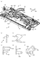
- A An exploded perspective view of a base and an adjustment mechanism of a circular saw in the first embodiment of the present invention, (b) a side view and (c) a rear view of a stopper plate, and (d) a top view of a sub link.
- E Side view and (f) Front view. It is the rear view of the circular saw in the 1st Embodiment of this invention, Comprising: The figure which showed the partial cross section.
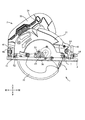
- the rear view at the time of tilting of the circular saw in the 1st Embodiment of this invention Comprising: The figure which showed the partial cross section. It is a side view of the circular saw in the 1st Embodiment of this invention, Comprising: The figure which shows the state which mounted
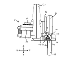
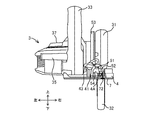
- wore with the sub-base of the circular saw in the 1st Embodiment of this invention Comprising: The figure which showed the partial cross section.
- FIG. 11A is a top view of a base and an adjustment mechanism used in a circular saw according to a second embodiment of the present invention
- FIG. 11B is a cross-sectional view taken along the line 11b-b in a state where a sub-base is mounted.
- the circular saw 1 includes a motor 2, a housing 3, a base 4, an adjustment mechanism 5, and a cutting blade 6.
- the base 4 can be mounted with a sub-base 7 on the lower surface thereof.
- the direction of the circular saw 1 is determined based on the viewpoint of the circular saw 1 from the user. Specifically, the vertical and forward / backward directions are determined in the directions indicated by the arrows in FIG.
- the front side in FIG. 1 is the right side of the circular saw 1
- the back side of the paper is the left side of the circular saw 1.
- the motor 2 is accommodated in the housing 3 as shown in FIG.
- the motor 2 has a rotating shaft 2A extending in the left-right direction, and includes a pinion 21 fixed to the right end portion of the rotating shaft 2A.
- the pinion 21 is engaged with a reduction mechanism (not shown) composed of a plurality of gears, and the reduction mechanism (not shown) is engaged with the gear 22 below the pinion 21.
- the gear 22 is fixed to the left end portion of the output shaft 23 extending left and right, and the cutting blade 6 is detachably attached to the right end portion of the output shaft 23. Specifically, the cutting blade 6 is sandwiched between the washer 24 and the output shaft 23.
- the washer 24 is fixed by a bolt 25 that is screwed to the output shaft 23.
- the driving force generated in the motor 2 is transmitted to the cutting blade 6 via the pinion 21, a reduction mechanism (not shown), the gear 22, and the output shaft 23.
- the housing 3 forms an outer shell of the circular saw 1 and accommodates the motor 2 and the like.
- the housing 3 includes a saw cover 31 that covers the upper portion of the cutting blade 6, a protective cover 32 that covers the lower portion of the cutting blade 6, a handle 33, a trigger 34, a grip 35, a gear 22, and a gear cover 36 that houses the output shaft 23.
- the saw cover 31 is disposed on the right side of the handle 33 so as to cover the upper portion of the cutting blade 6.
- the protective cover 32 is provided so as to cover the rear part and the lower part of the cutting blade 6. Further, the protective cover 32 is disposed in a nested manner inside the saw cover 31 and is rotatable along the outer edge of the cutting blade 6 around the output shaft 23.
- a spring (not shown) is interposed between the protective cover 32 and the saw cover 31, and the spring (not shown) biases the protective cover 32 against the saw cover 31 in the rotation direction of the cutting blade 6. That is, the protective cover 32 is biased counterclockwise when viewed from the right side.
- the handle 33 has a substantially D shape in side view and extends above the motor housing portion 37.
- the handle 33 extends from the front to the rear so that the user can easily hold it.
- a trigger 34 that is electrically connected to the motor 2 and is used for driving and stopping the motor 2 is provided below the handle 33.
- a grip 35 that extends to the left from the handle 33 and is gripped by the user is provided at the rear portion of the handle 33.
- the gear cover 36 extends further to the right from the right part of the motor housing part 37 (FIG. 2).
- the lower surface of the gear cover 36 is formed on a substantially flat plate.
- the gear cover 36 constitutes the lower part of the housing 3 and accommodates the gear 22 and the output shaft 23. From the right end of the gear cover 36, the output shaft 23 projects rightward.
- the base 4 is a substantially flat plate-like member that extends in the front-rear and left-right directions below the circular saw 1.
- the lower portion of the base 4 is formed in a substantially flat shape so as to be in contact with the workpiece and to be slidable.
- the base 4 supports the housing 3 so as to be tiltable about the tilting shaft 4A, and the angle of the cutting blade 6 with respect to the base 4 can be adjusted.
- the base 4 supports the front end portion of the saw cover 31 so as to be swingable via the swing shaft 3A (FIG. 1), so that the protruding amount of the cutting blade 6 from the base 4 can be adjusted.
- An opening 4a is formed in the right part of the base 4 in the front-rear direction.
- the cutting blade 6 is arrange
- a screw hole 4b penetrating in the front-rear direction is formed in the rear portion of the base 4. The inside of the screw hole 4b is threaded and used to fix the sub-base 7.
- a bevel plate 41 extending upward is provided on the upper surface of the rear portion of the base 4, and a connection plate 42 extending upward is provided on the upper surface of the front portion.
- the bevel plate 41 is a substantially flat plate-like member that forms a substantially fan shape in rear view.
- a locking hole 41 a penetrating in the front-rear direction is formed in the lower part of the bevel plate 41.
- the center of the locking hole 41a substantially coincides with the tilting shaft 4A.
- long holes 41b and 41c are formed in the upper part of the bevel plate 41.
- the long holes 41b and 41c are formed in an arc shape over a predetermined length, and the center of the arc substantially coincides with the center of the locking hole 41a and the tilting shaft 4A.
- connection plate 42 is a substantially flat member that forms a substantially sector shape when viewed from the front.
- An engagement hole 42 a penetrating in the front-rear direction is formed in the lower portion of the connection plate 42.
- the center of the engagement hole 42a substantially coincides with the tilt axis 4A.
- a long hole 42 b is formed in the upper part of the connection plate 42.
- the long hole 42b is formed in an arc shape over a predetermined length, and the center of the arc substantially coincides with the center of the engagement hole 42a and the tilt shaft 4A.
- a fixing tool (not shown) is inserted through the engagement hole 42a, and the fixing tool (not shown) engages with the front portion of the housing 3 so as to be tiltable.
- a butterfly bolt 44 is inserted back and forth in the long hole 42 b, and the butterfly bolt 44 is screwed into the front portion of the housing 3. The user can fix the tilting posture of the housing 3 with respect to the base 4 by operating the butterfly bolt 44. Specifically, when the user tightens the butterfly bolt 44, the head of the butterfly bolt 44 is pressed against the connection plate 42, and the housing 3 is fixed.
- the adjustment mechanism 5 mainly includes a stopper plate 51, a sub link 52, a link 53, and a spring 54.
- the stopper plate 51 is a substantially flat member and is disposed in front of the bevel plate 41.
- the stopper plate 51 includes an abutting portion 51A whose upper portion is formed in an arc shape, a base portion 51B, a hole 51c formed in the lower portion of the stopper plate 51, and a convex portion 51D.
- the stopper plate 51 is disposed immediately before the bevel plate 41 so that the center of the hole 51c coincides with the tilt axis 4A.
- the stopper plate 51 is tiltably connected to the bevel plate 41 by inserting the shaft 52D through the hole 51c and the locking hole 41a.
- the upper end of the contact portion 51A is formed in a substantially arc shape with the hole 51c as the center.
- the central angle of the arc is designed to be equal to or greater than the maximum tilt angle with respect to the base 4 of the housing 3. Since the maximum tilt angle in the circular saw 1 according to the present embodiment is 45 degrees, the upper portion of the contact portion 51A is formed in an arc shape with a central angle of 45 degrees.
- the contact portion 51 ⁇ / b> A has a function of restricting the downward swing of the housing 3 by contacting the rear end portion of the saw cover 31.
- the base 51B is formed to protrude rightward at the lower part of the stopper plate 51.
- the base 51B is disposed above the screw hole 4b.
- the convex portion 51D is formed to extend in the front-rear direction.
- the rear end portion of the convex portion 51D is arranged to engage with the long hole 41c.
- the spring 54 is a coil spring and is disposed inside the long hole 41c.
- the upper end portion of the spring 54 abuts on the convex portion 51D of the stopper plate 51, and urges the convex portion 51D substantially upward along the shape of the long hole 41c. Therefore, the stopper plate 51 is urged clockwise in the rear view when the sub-base 7 is not attached.
- the sub link 52 is a substantially flat plate-like member and is disposed in front of the bevel plate 41 and the stopper plate 51.
- the sub link 52 has a pair of arm portions 52A.
- a long hole 52 b is formed in the upper part of the sublink 52, and a hole 52 f is formed in the lower part of the sublink 52.
- the pair of arm portions 52 ⁇ / b> A includes two flat plates formed so as to extend in the front-rear direction, and constitutes the front portion of the sublink 52.
- the long hole 52b is formed so as to penetrate the sub-link 52 in the front-rear direction, and is formed in a substantially arc shape centered on the hole 52f in the front view.
- a washer 52E having a thickness substantially equal to that of the stopper plate 51 is disposed between the sub link 52 and the bevel plate 41. *
- a contact portion 52G is formed on the upper right side of the sub link 52.
- the contact portion 52G has a function of restricting the downward swing of the housing 3 by contacting the rear end portion of the saw cover 31.
- the upper end of the contact portion 52G is positioned below the upper end of the contact portion 51A of the stopper plate 51.
- the upper end of the contact portion 52G is located about twice as low as the thickness of the sub-base 7 from the upper end of the contact portion 51A, specifically about 5 millimeters below the upper end of the contact portion 51A.
- the sub link 52 is disposed in front of the stopper plate 51.
- the shaft 52D is inserted through the hole 52f, and the rear end portion of the shaft 52D is inserted through the locking hole 41a of the bevel plate 41 as described above. In this way, the sub link 52 is tiltably connected to the bevel plate 41.
- a screw 52C is inserted through the long hole 52b in the front-rear direction.
- the screw 52 ⁇ / b> C is inserted into the washer 52 ⁇ / b> E and the long hole 41 b in addition to the long hole 52 b, and the rear end portion is screwed into the wing nut 43.
- the user can fix and change the tilting posture of the sub link 52 by fastening and releasing the wing nut 43. Specifically, when the user tightens the wing nut 43, the head of the wing nut 43 is pressed against the bevel plate 41, and the housing 3 is fixed. When the fastening of the butterfly bolt 44 is loosened and the fastening of the wing nut 43 is further loosened, the fixed state of the housing 3 is released, and the user can freely change the tilting posture of the housing 3.
- the link 53 is a member that forms an arc shape in a side view.
- the link 53 is formed with a long hole 53b that penetrates the link 53 in the left-right direction and forms an arc shape in a side view.
- the link 53 is pivotally connected to the front end portions of the pair of arm portions 52A at the lower portion, and defines a rotation shaft 53A. Therefore, the link 53 can rotate around the rotation shaft 53A. Further, since the link 53 is connected to the front end portions of the pair of arm portions 52A, the link 53 can be tilted integrally with the sub link 52.
- the link 53 corresponds to the link mechanism of the present invention.
- the link 53 and the sub link 52 correspond to the first adjustment mechanism of the present invention.
- the link 53 is connected to the saw cover 31 via a screw (not shown). Specifically, a screw (not shown) is inserted in the left and right direction into the long hole 53 b and screwed into the left side surface of the saw cover 31. The user can lock the saw cover 31 to the link 53 by tightening the top of a screw (not shown) to the link 53. That is, the link 53 has a function of changing and holding the swinging posture of the housing 3. Further, since the sub link 52 and the link 53 can be tilted integrally, the user can change the tilting posture of the housing 3 while maintaining the state in which the housing 3 is locked to the link 53.
- the sub-base 7 is a substantially flat member that can be mounted on the lower surface of the base 4 (FIG. 6). In the present embodiment, the thickness of the sub-base 7 is about 2.5 millimeters.
- the sub base 7 includes a mounting screw 72.
- FIGS. 7 and 8 are cross-sectional views around the stopper plate 51 and the mounting screw 72 for understanding the structure.
- the sub base 7 In the mounting operation of the sub base 7, the sub base 7 is brought into contact with the lower surface of the base 4, and the mounting screw 72 is inserted from the lower surface of the sub base 7 and screwed into the screw hole 4b (FIGS. 7 and 8). .
- the mounting screw 72 has a length that greatly exceeds the thickness dimension of the base 4 and the sub-base 7. Therefore, the mounting screw 72 protrudes from the upper surface of the base 4 in a state where it is screwed into the screw hole 4b for mounting the sub-base 7 (FIGS. 7 and 8).
- the upper end portion of the mounting screw 72 protruding from the upper surface of the base 4 is in contact with the base portion 51B disposed above the screw hole 4b. Since the base 51B is pushed upward by the mounting screw 72, the stopper plate 51 rotates counterclockwise when viewed from the rear against the biasing force of the spring 54 (FIGS. 6 to 8).
- the position where the mounting screw 72 is not screwed and the stopper plate 51 is rotated clockwise by the biasing force of the spring 54 (FIGS. 1 to 5) is defined as the second position.
- the position (FIGS. 6 to 8) where the stopper plate 51 is rotated counterclockwise by the mounting screw 72 is defined as the first position. That is, the stopper plate 51 is configured to be movable between the first position and the second position in conjunction with the attachment / detachment of the sub base 7 to / from the base 4.
- the motor 2 When the user pushes the trigger 34, the motor 2 is started, and the driving force is transmitted from the pinion 21 to the output shaft 23 via a speed reduction mechanism and a gear 22 (not shown). Further, the driving force is transmitted from the output shaft 23 to the cutting blade 6.
- the user performs a cutting operation by pressing and sliding the material to be cut against the lower portion of the base 4.
- the front end portion of the protective cover 32 comes into contact with the material to be cut, and the protective cover 32 rotates clockwise as viewed from the right side against the urging force.
- bevel cutting by operating the wing nut 43 and the wing bolt 44, tilting the housing 3 about the tilting shaft 4A, and adjusting the angle of the cutting blade 6.
- the amount of protrusion of the cutting blade 6 from the base 4 can be adjusted by swinging the housing 3. A detailed method for adjusting the protrusion amount is shown below.
- the housing 3 can swing around the swing shaft 3A.
- the user operates a screw (not shown) inserted through the long hole 53 a to release the lock between the link 53 and the saw cover 31 and swings the housing 3 to an arbitrary position. Thereafter, by locking the saw cover 31 to the link 53, the user fixes and holds the swing position of the housing 3.
- the cutting blade 6 swings substantially vertically. Therefore, the protrusion amount of the cutting blade 6 from the base 4 can be changed, and therefore the cutting depth of the cutting blade 6 can be adjusted.
- the maximum value of the cutting depth of the cutting blade 6 (hereinafter referred to as “maximum cutting depth”) is defined by the saw cover 31 and the stopper plate 51 or the sub link 52.
- the maximum cutting depth of the cutting blade 6 is defined by the saw cover 31 and the stopper plate 51.
- the stopper plate 51 is disposed at the second position in a non-mounted state (FIGS. 1 to 5).
- the contact portion 51A of the stopper plate 51 in the second position is located above the contact portion 52G of the sub link 52 and can contact the rear end portion of the saw cover 31. For this reason, the downward swing of the housing 3 is regulated by the contact between the saw cover 31 and the stopper plate 51. That is, the maximum cutting depth of the cutting blade 6 in the non-mounted state is defined by the saw cover 31 and the stopper plate 51.
- the contact portion 51A of the stopper plate 51 forms an arc shape centered on the tilting shaft 4A. Therefore, as shown in FIG. 5, the rear end portion of the saw cover 31 can contact the contact portion 51A even when the housing 3 is tilted. Therefore, the maximum cutting depth of the cutting blade 6 is kept constant regardless of the tilting posture of the housing 3.
- the maximum cutting depth of the cutting blade 6 is defined by the saw cover 31 and the sub link 52. Details are described below.
- the stopper plate 51 is disposed at the first position when the sub-base 7 is mounted (FIGS. 6 to 8). When in the first position, as shown in FIG. 6, the contact portion 51 ⁇ / b> A of the stopper plate 51 is disposed below the saw cover 31. For this reason, the contact portion 52G of the sub link 52 and the rear end portion of the saw cover 31 can be contacted. Therefore, the maximum cutting depth of the cutting blade 6 with the sub-base 7 attached is defined by the saw cover 31 and the sub-link 52.
- the contact portion 52G is positioned below the contact portion 51A of the stopper plate 51 in the second position by about 5 millimeters.
- the front end portion and the rear end portion of the saw cover 31 are supported, and the centers of the output shaft 23 and the cutting blade 6 are positioned in the vicinity of the front and rear midpoints of the front end portion and the rear end portion of the saw cover 31 in a side view (see FIG. 1). Therefore, as compared with the non-mounted state of the sub-base 7, the cutting blade 6 in the mounted state of the sub-base 7 is increased by about 2.5 millimeters and can swing downward. That is, the cutting blade 6 can swing downward by an amount corresponding to the thickness of the sub-base 7, and therefore the maximum cutting depth of the cutting blade 6 does not change even when the sub-base 7 is mounted.
- the sub link 52 can tilt around the tilt axis 4A.
- the sub link 52 is locked to the saw cover 31, that is, the housing 3 via the link 53. Therefore, the sub link 52 can be tilted integrally with the housing 3 as shown in FIG.
- the rear end portion of the saw cover 31 and the contact portion 52G can always contact each other regardless of the tilting posture (FIG. 8). Therefore, even when the sub-base 7 is mounted, the maximum cutting depth of the cutting blade 6 is kept constant regardless of the tilting posture of the housing 3.
- the maximum cutting depth of the cutting blade 6 can be made equal in the mounted state and the non-mounted state of the sub-base 7. That is, loss of the maximum cutting depth due to the thickness of the sub base 7 can be prevented. Therefore, a cutting material that can be cut when the sub-base 7 is not mounted can be selected as a target for cutting work even when the sub-base 7 is mounted.
- the maximum cutting depth of the cutting blade 6 can be maintained by contacting the stopper plate 51 even when the housing 3 is tilted. is there.
- the maximum depth of cut can be adjusted by the housing 3 coming into contact with the sub link 52.
- the maximum cutting depth of the cutting blade 6 is automatically adjusted by the attachment / detachment of the sub-base 7. The Therefore, the user can easily adjust the maximum cutting depth without operating the adjustment mechanism 5. Further, since the movement of the stopper plate 51 is interlocked with the attachment / detachment of the sub-base 7, the user can surely carry out the adjustment of the maximum cutting depth without forgetting.
- the stopper plate 51 is prevented from moving from the second position when the sub-base 7 is not attached. This prevents accidental fluctuations in the maximum depth of cut during work.
- the stopper plate 51 moves between the second position and the first position, and the swing position of the housing 3 and the maximum cutting depth of the cutting blade 6 are as follows. Realized the adjustment.
- the present invention is not limited to such an embodiment.
- the present invention includes various embodiments that facilitate adjustment of the maximum cutting depth of the cutting blade 6.
- a circular saw 101 according to a second embodiment will be described with reference to FIGS.
- the same members as those in the first embodiment are denoted by the same reference numerals, and description thereof is omitted.
- parts / members corresponding to parts / members constituting the circular saw 1 according to the first embodiment are denoted by reference numbers obtained by adding 100 to the drawing reference numbers of the first embodiment.
- the adjustment mechanism 105 in the second embodiment includes a spring 154.
- the spring 154 is a coil spring, and a shaft 52D is inserted back and forth in the center of the coil.
- the spring 154 is disposed so as to be embedded in the bevel plate 141 (FIG. 11), and its front end abuts against the rear surface of the stopper plate 151 and biases it forward.
- the washer 152E has a larger thickness than the stopper plate 151, unlike the washer 52E in the first embodiment.
- the stopper plate 151 has a contact portion 151A at the top.
- the contact portion 151A is formed in a substantially rectangular shape when viewed from the front.
- the upper end of the contact portion 151A is located approximately 5 millimeters higher than the upper end of the contact portion 152G of the sub link 152 in front view or rear view.
- the stopper plate 151 has a protruding portion 151E protruding forward, and the protruding portion 151E engages with the sub link 152 (FIGS. 9 and 11). When the protrusion 151E engages with the sub link 152, the stopper plate 151 and the sub link 152 can be tilted together.
- the stopper plate 151 is movable between a rear first position (FIGS. 10A and 11) and a front second position (FIGS. 10B and 12). In the first position, the stopper plate 151 contacts the bevel plate 141. In the second position, the stopper plate 151 contacts the sub link 152. Since the stopper plate 151 is urged forward by the spring 154, the stopper plate 151 is disposed at the second position when the sub-base 107 is not attached (FIG. 10B).
- the sublink 152 is formed such that the lower part is bent forward.
- the sub-base 107 includes two protrusions 172 that protrude upward.
- the vertical dimension of the two protrusions 172 is sufficiently longer than the thickness of the base 4 and the sub-base 7.
- the thickness of the sub-base 107 is about 2.5 millimeters as in the case of the sub-base 7 in the first embodiment.
- the two protrusions 172 protrude greatly upward from the upper surface of the base 4.
- the two protrusions 172 are inserted between the stopper plate 151 and the sub link 152.
- the stopper plate 151 moves backward and is arranged at the first position.
- a spring 154 is arranged between the two protrusions 172, and a force can be applied evenly on the left and right sides of the spring 154, so that the stopper plate 151 can be retracted appropriately.
- the rear end portion of the saw cover 31 can come into contact with the contact portion 152G of the sub link 152.
- FIGS. 10B and 12 show a state in which the sub-base 107 is not attached.
- the sub-base 107 In the non-mounted state, the sub-base 107 is biased forward by the spring 154 and is disposed at the second position. In this case, the rear end portion of the saw cover 31 can come into contact with the contact portion 151 ⁇ / b> A of the stopper plate 151.
- the contact portion 151A is located 5 millimeters above the contact portion 152G of the sub link 152. Therefore, the maximum cutting depth of the cutting blade 6 does not change between the non-mounted state and the mounted state. That is, as compared with the non-mounted state, the cutting blade 6 in the mounted state of the sub-base 107 can swing downward by about 2.5 millimeters to cancel the thickness of the sub-base 107. Therefore, the maximum cutting depth is equal to that in the non-wearing state.
- the maximum cutting depth of the cutting blade 6 is maintained even when the housing 3 is tilted. Specifically, when the housing 3 tilts, the sub link 152 and the stopper plate 151 also tilt together. Therefore, the saw cover 31 can always come into contact with the stopper plate 151 when the sub-base 107 is not attached, regardless of the tilting posture, and can always come into contact with the sub-link 152 when it is attached. Therefore, the maximum cutting depth of the cutting blade 6 is maintained even during tilting.
- the maximum cutting depth of the cutting blade 6 is maintained by being able to contact the stopper plate 151 even if the housing 3 is tilted. Is possible.
- the maximum depth of cut can be adjusted by the housing 3 coming into contact with the sub link 152.
- the maximum cutting depth of the cutting blade 6 is automatically set by the attachment / detachment of the sub base 107. Adjusted. Therefore, the user can easily adjust the maximum cutting depth without directly operating the adjustment mechanism 105. Further, the user can surely carry out the adjustment of the maximum cutting depth without forgetting.
- the stopper plate 151 is prevented from moving from the second position when the sub base 107 is not attached. For this reason, inadvertent fluctuations in the maximum depth of cut during work are prevented.
- the stopper plate 151 is moved between the second position and the first position, and the swing position of the housing 3 and the maximum cutting depth of the cutting blade 6 are adjusted.
- the present invention is not limited to such an embodiment.
- the present invention includes various embodiments that facilitate adjustment of the maximum cutting depth of the cutting blade 6.
- a circular saw 201 according to a third embodiment will be described with reference to FIGS.
- the same members as those in the first embodiment are denoted by the same reference numerals, and description thereof is omitted.
- parts / members corresponding to parts / members constituting the circular saw 1 according to the first embodiment are denoted by reference numbers obtained by adding 200 to the drawing reference numbers of the first embodiment.
- a circular saw 201 with the sub-base 7 attached is shown in FIG. 13, and a non-attached circular saw 201 is shown in FIG.
- the adjustment mechanism 205 in the third embodiment does not include a stopper plate.
- a sub link 252 is arranged in front of the bevel plate 41.
- the sub link 252 can be tilted about the tilt axis 4A as in the other embodiments. Further, the sub-link 252 supports the link 53 so as to be able to tilt together and turn as in the first embodiment.
- the sub link 252 includes a support portion 252H protruding forward (FIGS. 13 and 14).
- the support portion 252H is formed in a flat plate shape that extends in a substantially front-rear direction and a substantially left-right direction.
- the sub link 252 has a screw 255 that is screwed into the support portion 252H.
- the screw 255 is screwed with the support portion 252H so that the shaft extends substantially in the vertical direction.
- the screw 255 is a headless hexagon socket head screw.
- a regular hexagonal recess that can be engaged with a hexagon wrench is formed at the top of the screw 255.
- the top portion of the screw 255 has a function of contacting the rear end portion of the saw cover 31.
- the screw 255 is movable between a first position (FIG. 13) close to the tilt shaft 4A or the base 4 and a second position (FIG. 14) spaced apart.
- the user can move the screw 255 substantially vertically between the first position and the second position by rotating the screw 255 with a hexagon wrench or the like and screwing the screw 255 back and forth with respect to the support portion 252H. it can.
- the moving distance of the screw 255 between the first position and the second position is about 5 millimeters.
- the top of the screw 255 in the first position is located closer to the tilt axis 4A by about 5 millimeters than the top of the screw 255 in the second position.
- the screw 255 When the sub-base 7 is not attached, the screw 255 is disposed at the second position (FIG. 14). On the other hand, when the sub-base 7 is mounted, the cutting blade 6 can have the maximum cutting depth equal to the maximum cutting depth in the non-mounted state by disposing the screw 255 in the first position (FIG. 13). .
- the rear end portion of the saw cover 31 comes into contact with the top portion of the screw 255 at the first position. Therefore, the screw 255 can swing downward by about 5 millimeters as compared with the case where it abuts on the screw 255 at the second position. As a result, the cutting blade 6 can swing downward by about 2.5 millimeters, that is, by the thickness of the sub-base 7. Therefore, the maximum cutting depth of the cutting blade 6 can be kept constant regardless of whether the sub-base 7 is attached or not.
- the maximum cutting depth of the cutting blade 6 is maintained.
- the screw 255 is supported on the sublink 252. Since the sub link 252 can tilt about the tilt axis 4A, the distance of the screw 255 from the tilt axis 4A does not change even when the housing 3 tilts. Therefore, the maximum cutting depth of the cutting blade 6 is kept constant regardless of the tilting posture of the housing 3.
- the sub link 252 and the screw 255 can be tilted integrally with the sub link, the contact between the screw 255 and the saw cover 31 is maintained even when the housing 3 is tilted. . Further, a mechanism for adjusting the maximum cutting depth is realized by a simple configuration of the screw 255.
- the adjustment mechanisms 5, 105, and 205 have the sub-links 52, 152, and 252.
- the present invention is not necessarily configured to include sublinks.
- the present invention can be implemented even in a circular saw in which the adjustment mechanism does not include a sub-link and includes a mechanism that adjusts the swinging posture of the housing by the link.
- a stopper plate is disposed between the link and the bevel plate so that it can move between the first position and the second position. The maximum cutting depth of the cutting blade can be adjusted by bringing the saw cover into contact with the stopper plate at the second position when the sub-base is not attached and bringing the link and the saw cover into contact with the sub-base attached. is there.
- the maximum cutting depth of the cutting blade may be adjusted by providing a screw on the link and moving the screw between the first position and the second position.
- the present invention can also be implemented in a circular saw having a mechanism in which the saw cover comes into contact with the base.
- the maximum cutting depth of the cutting blade may be adjusted by disposing a contact member such as a screw or a stopper plate on the base and moving between the first position and the second position.
- the stopper plates 51 and 151 and the screw 255 correspond to the contact member of the present invention.
- the springs 54 and 154 correspond to the biasing member of the present invention.
Landscapes
- Life Sciences & Earth Sciences (AREA)
- Engineering & Computer Science (AREA)
- Mechanical Engineering (AREA)
- Wood Science & Technology (AREA)
- Forests & Forestry (AREA)
- Sawing (AREA)
Abstract
切断刃の最大切込み深さを調整可能な丸鋸を提供する。切断刃6を突出させる開口4aが形成され、切断材上を摺動可能で所定の厚さを有するサブベース7が着脱可能なベース4と、該切断刃を回転駆動するモータ2と、該モータを支持し収容するとともに該切断刃を覆い、該切断刃の突出量を変更可能なように該ベースに対して揺動軸の軸心を中心に揺動可能に支持されるハウジング3と、該切断刃の突出量を調整して切断材に対する切込み深さを調整する調整機構5、を有し、該調整機構は、該サブベースを該ベースへ装着した装着状態における該切込み深さの最大値と、該サブベースを非装着とした非装着状態における該切込み深さの最大値とが等しくなるように構成されていることを特徴とする丸鋸を提供する。
Description
本発明は丸鋸に関し、特にサブベースの取付を可能とした切断機に関する。
従来の切断機として、モータを収容し切断刃を支持するハウジングと、ハウジング下部に設けられて切断刃を下方に突出させるベースとを備え、さらにベースの下面においてサブベースを着脱可能とした構成が知られている(特許文献1)。
従来の切断機では、サブベースをベースに装着した場合、サブベースの厚み分だけ切断刃の突出量が減少してしまい、切込み深さが減少してしまうという課題があった。これは、切断機の一種である丸鋸についても共通の課題であった。
本発明は、斯かる実情に鑑み、サブベースをベースに装着した場合であっても切込み深さの減少を防止することが可能な丸鋸を提供する。
上記課題を解決するため、本発明は、切断刃を突出させる開口が形成され、切断材上を摺動可能で所定の厚さを有するサブベースが着脱可能なベースと、該切断刃を回転駆動するモータと、該モータを支持し収容するとともに該切断刃を覆い、該切断刃の突出量を変更可能なように該ベースに対して揺動軸の軸心を中心に揺動可能に支持されるハウジングと、該切断刃の突出量を調整して切断材に対する切込み深さを調整する調整機構と、を有し、該調整機構は、該サブベースを該ベースへ装着した装着状態における該切込み深さの最大値と、該サブベースを非装着とした非装着状態における該切込み深さの最大値とが等しくなるように構成されていることを特徴とする丸鋸を提供する。
上記構成によれば、切断刃の最大切込み深さを、サブベース装着状態においても非装着状態と等しい量とすることができる。すなわち、サブベースの厚みによる最大切込み深さの損失を防ぐことができる。サブベース非装着状態で切断可能であった切断材を、非装着状態での作業においても切断作業の対象として選定することができる。
該調整機構は、該ハウジングと当接可能であり該ベースに対する位置を第1位置と第2位置との間で変更可能な当接部材を有し、該当接部材の位置の変更によって該ハウジングの該ベースに対する揺動位置を変更し、該切込み深さの最大値を調整可能とすることが好ましい。
上記構成によれば、当接部材の位置の変更によって、最大切込み深さをサブベース装着状態においても非装着状態と等しい量とすることができる。そのため、簡易な構造と簡易な操作によって、最大切込み深さの調整が可能である。またサブベースの厚みによる最大切込み深さの損失を防ぐことができる。サブベース非装着状態で切断可能であった切断材を、非装着状態での作業においても切断作業の対象として選定することができる。
該調整機構は、該切断刃の側面と該ベースとの角度が変更可能となるよう、該揺動軸の軸心と直交する傾動軸を中心に該ベースに対して傾動可能に該ハウジングを支持し、該ハウジングの揺動位置を固定可能に構成される第1調整機構と、該当接部材を備えた第2調整機構とを備え、該ハウジングは、該非装着状態において該第2位置にある該当接部材と当接し、該装着状態において該第1調整機構と当接するとともに該当接部材は該第1位置にあることが好ましい。
該第1調整機構は、該傾動軸を中心に該ベースに対して傾動可能に支持されるサブリンクと、一体的に傾動可能に該サブリンクと接続され、該ハウジングの揺動位置を固定可能なリンク機構と、を備え、該ハウジングは、該非装着状態において該第2位置にある該当接部材と当接し、該装着状態において該サブリンクと当接するとともに該当接部材は該第1位置にあることが好ましい。
上記構成によれば、サブベース非装着状態では、ハウジングが傾動しても第1調整機構またはサブリンクと当接することによって、切断刃の最大切込み深さを維持することが可能である。また、サブベース装着状態では、ハウジングが当接部材と当接することによって最大切込み深さを調整することが可能である。
該サブベースは、該装着状態で該当接部材に当接可能であり、該当接部材は、該サブベースの該ベースへの装着に連動して該第2位置から該第1位置に移動し、該サブベースが該ベースから取外されることに連動して該第1位置から該第2位置に移動することが好ましい。
上記構成によれば、サブベースの着脱に連動して当接部材の移動が行われるため、サブベースの着脱によって自動的に最大切込み深さが調整される。そのため、ユーザは調整機構を操作することなく、容易に最大切込み深さの調整を行うことが可能となる。また、当接部材の移動がサブベースの着脱に連動するため、ユーザは、最大切込み深さの調整を、忘れることなく確実に実施することができる。
該第2調整機構は、該当接部材を該第1位置から該第2位置に向かう方向に付勢する付勢部材をさらに備え、該当接部材は、該ベースに対して回動可能に設けられ、該サブベースを装着するときに該サブベースと当接して回動可能であることが好ましい。
上記構成によれば、付勢部材を備えているため、作業時に当接部材が勝手に移動することが防止される。そのため、作業時における最大切込み深さの不慮の変動が防止される。
該第2調整機構は、該サブリンクに対して一体的に傾動可能に接続されていることが好ましい。
該第2調整機構は、該当接部材を該第1位置から該第2位置に向かう方向に付勢する付勢部材をさらに備え、該当接部材は、該第2位置と該第1位置との間を直線状に移動可能であることが好ましい。
上記構成によれば、第2調整機構がサブリンクと一体に傾動可能であるため、傾動した場合でもハウジングと第2調整機構との当接を維持する機構を、簡易な構造によって実現することができる。
該調整機構は、該切断刃の側面と該ベースとの角度が変更可能となるよう、該揺動軸の軸心と直交する傾動軸を中心に該ベースに対して傾動可能に支持されるサブリンクと、一体的に傾動可能に該サブリンクと接続され、該ハウジングの揺動位置を固定可能なリンク機構と、をさらに備え、該当接部材は、該傾動軸に対して近接及び離間可能となるように該サブリンクに螺合するネジを備えることが好ましい。
上記構成によれば、傾動可能なサブリンクにネジが設けられ、ネジの位置を変更するによってハウジングの揺動位置を変更するため、どのような傾動角度であっても揺動位置の変更し、維持することが可能である。また、簡易な構造によって調整機構を実現できる。
本発明の丸鋸によれば、サブベースをベースに装着した場合であっても切込み深さの減少を防止することが可能な丸鋸を提供できる。
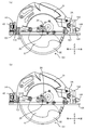
<第1の実施の形態> 以下、本発明の第1の実施の形態による丸鋸1について図1から図8に基づき説明する。丸鋸1は、図1及び図2に示されるように、モータ2と、ハウジング3と、ベース4と、調整機構5と、切断刃6とを備える。ベース4は、図6乃至図8に示すように、その下面にサブベース7を装着可能である。
なお説明の便宜上、丸鋸1のユーザからの視点に基づき、丸鋸1の方向を定める。具体的には、図1のそれぞれの矢印で示す方向に、上下及び前後の方向を定める。図1の紙面手前側を丸鋸1の右側とし、紙面奥側を丸鋸1の左側とする。
モータ2は、図2に示すように、ハウジング3に収容される。モータ2は左右方向に延びる回転軸2Aを有し、回転軸2Aの右端部に固定されたピニオン21を備える。ピニオン21は、複数のギヤから構成される不図示の減速機構と係合し、この不図示の減速機構は、ピニオン21の下方においてギヤ22と係合する。ギヤ22は左右に延出する出力軸23の左端部に固定され、出力軸23の右端部では、切断刃6が着脱可能に装着される。詳細には、切断刃6はワッシャ24と出力軸23との間に挟持される。またワッシャ24は、出力軸23に螺合するボルト25によって固定される。
上記構成により、モータ2において発生した駆動力は、ピニオン21、不図示の減速機構、ギヤ22、及び出力軸23を介して、切断刃6に伝達される。
ハウジング3は、図1に示すように丸鋸1の外殻を形成し、モータ2等を収容する。ハウジング3は、切断刃6の上部を覆うソーカバー31と、切断刃6の下部を覆う保護カバー32と、ハンドル33と、トリガ34と、グリップ35と、ギヤ22と出力軸23を収容するギヤカバー36と、モータ2とピニオン21と不図示の減速機構等を収容するモータ収容部37と、を有している。
ソーカバー31は、ハンドル33の右方において、切断刃6の上部を覆うように配置される。保護カバー32は、切断刃6の後部及び下部を覆うように設けられる。また、保護カバー32は、ソーカバー31の内部に入れ子状に配置され、出力軸23を中心として切断刃6の外縁に沿うように回動可能である。保護カバー32とソーカバー31との間には図示せぬバネが介在し、この図示せぬバネは、ソーカバー31に対して保護カバー32を、切断刃6の回転方向へ付勢する。すなわち、保護カバー32は、右側面視において反時計回りに付勢される。
ハンドル33は、モータ収容部37の上方に延出した側面視略D型の形状を有する。ハンドル33は、ユーザが把持しやすいように前方から後方に延びる。ハンドル33の下部には、モータ2と電気的に接続し、モータ2の駆動操作及び停止操作に用いられるトリガ34が設けられる。ハンドル33の後部には、図4等に示すように、ハンドル33から左方に延出する、ユーザが把持するためのグリップ35が備えられる。
ギヤカバー36は、モータ収容部37の右部からさらに右方に延出する(図2)。ギヤカバー36の下面は、略平板上に形成される。ギヤカバー36は、ハウジング3の下部を構成し、ギヤ22と出力軸23とを収容する。ギヤカバー36の右端部からは、出力軸23が右方に突出する。
ベース4は、図3に示すように、丸鋸1の下部において、前後左右方向に延びる略平板状の部材である。ベース4の下部は、被加工部材と当接し摺動可能とするため、略平面状に形成される。ベース4は、傾動軸4Aを中心にしてハウジング3を傾動可能に支持し、切断刃6のベース4に対する角度を調整可能としている。またベース4は、揺動軸3Aを介してソーカバー31の前端部を揺動可能に支持しており(図1)、切断刃6のベース4からの突出量を調整可能としている。
ベース4の右部には、前後方向に亘って開口部4aが形成される。切断刃6は、開口部4aを介して下方に突出するように配置される(図1)。また、ベース4の後部には、前後方向に貫通するネジ孔4bが形成される。ネジ孔4bの内部はねじ切りが施され、サブベース7を固定するために用いられる。
ベース4の後部上面には、上方に延出するベベルプレート41が備えられ、前部上面には、上方に延出する接続プレート42が備えられる。
ベベルプレート41は、後面視で略扇形を形成する略平板状の部材である。ベベルプレート41の下部には、前後方向に貫通した係止孔41aが形成される。係止孔41aの中心は、傾動軸4Aと略一致する。ベベルプレート41の上部には、長孔41b、41cが形成される。長孔41b、41cは、所定の長さに亘って弧状に形成され、弧の中心は、係止孔41aの中心及び傾動軸4Aと略一致する。
接続プレート42は、前面視で略扇形を形成する略平板状の部材である。接続プレート42の下部には、前後方向に貫通した係合孔42aが形成される。係合孔42aの中心は、傾動軸4Aと略一致する。接続プレート42の上部には、長孔42bが形成される。長孔42bは、所定の長さに亘って弧状に形成され、弧の中心は、係合孔42aの中心及び傾動軸4Aと略一致する。
係合孔42aには、不図示の固定具が挿通され、不図示の固定具はハウジング3の前部と傾動可能に係合する。長孔42bには、蝶ボルト44が前後に挿通され、蝶ボルト44はハウジング3の前部と螺合する。ユーザは、蝶ボルト44を操作することによって、ハウジング3のベース4に対する傾動姿勢を固定することができる。詳細には、ユーザが蝶ボルト44を締付けることによって蝶ボルト44の頭部が接続プレート42に押圧された状態となり、ハウジング3が固定される。
調整機構5は、図3に示すように、ストッパプレート51と、サブリンク52と、リンク53と、バネ54とを主に備える。
ストッパプレート51は、図3に示すように略平板状の部材であり、ベベルプレート41の前方に配置される。ストッパプレート51は、その上部が弧状に形成される当接部51Aと、基部51Bと、ストッパプレート51の下部に形成された孔51cと、凸部51Dとを備える。
ストッパプレート51は、ベベルプレート41の直前において、孔51cの中心が傾動軸4Aと一致するように配置される。軸52Dが孔51cと係止孔41aとに挿通されることにより、ストッパプレート51は、ベベルプレート41に対して傾動可能に接続される。
当接部51Aの上端は、図3(a)に示すように、孔51cを中心とした略弧状に形成される。弧の中心角は、ハウジング3のベース4に対する最大傾動角以上となるように設計される。本実施形態に係る丸鋸1における最大傾動角は45度であるため、当接部51Aの上部は、中心角を45度とした弧状に形成される。当接部51Aは、ソーカバー31の後端部と当接することによって、ハウジング3の下方への揺動を規制する機能を有する。
基部51Bは、ストッパプレート51の下部において右方に突出するように形成される。基部51Bは、ネジ孔4bの上方に配置される。
凸部51Dは、前後方向に延出するように形成される。凸部51Dの後端部は長孔41cに係合するように配置される。
バネ54は、コイルバネであり、長孔41cの内部に配置される。バネ54の上端部は、ストッパプレート51の凸部51Dと当接し、凸部51Dを長孔41cの形状に沿って略上方に付勢する。そのため、ストッパプレート51は、サブベース7が装着されていない状態では、後面視時計回りに付勢される。
サブリンク52は、図3に示すように略平板状の部材であり、ベベルプレート41及びストッパプレート51の前方に配置される。
サブリンク52は、一対の腕部52Aを有する。サブリンク52の上部には長孔52bが形成され、サブリンク52の下部には孔52fが形成される。一対の腕部52Aは、前後方向に延出するように形成された2つの平板から成り、サブリンク52の前部を構成する。長孔52bは、サブリンク52を前後に貫通して形成され、前面視において孔52fを中心とした略弧状に形成される。サブリンク52とベベルプレート41との間には、ストッパプレート51と略等しい厚みを有するワッシャ52Eが配置される。
サブリンク52の右側上部には、当接部52Gが形成される。当接部52Gは、ソーカバー31の後端部と当接することによって、ハウジング3の下方への揺動を規制する機能を有する。当接部52Gの上端は、ストッパプレート51の当接部51A上端よりも下方に位置する。本実施の形態において当接部52Gの上端は、当接部51A上端からサブベース7の厚みの2倍程度下方に、具体的には、当接部51A上端から5ミリメートル程度下方に位置する。
サブリンク52は、ストッパプレート51の前方に配置される。孔52fには軸52Dが挿通され、上述のように軸52Dの後端部はベベルプレート41の係止孔41aに挿通される。このようにして、サブリンク52はベベルプレート41に対して傾動可能に接続される。
長孔52bには、ネジ52Cが前後方向に挿通される。ネジ52Cは、長孔52bに加え、ワッシャ52Eと、長孔41bにも挿通され、後端部は蝶ナット43に螺合される。ユーザは、蝶ナット43の締結と解除とを行うことにより、サブリンク52の傾動姿勢を固定し、変更することができる。詳細には、ユーザが蝶ナット43を締付けることによって蝶ナット43の頭部がベベルプレート41に押圧された状態となり、ハウジング3が固定される。蝶ボルト44の締結を緩め、さらに蝶ナット43の締結を緩めると、ハウジング3の固定状態が解除され、ユーザは、ハウジング3の傾動姿勢を自由に変更することが可能となる。
リンク53は、側面視において弧状を形成する部材である。リンク53には、リンク53を左右方向に貫通し、側面視で弧状を成す長孔53bが形成される。リンク53は、下部において一対の腕部52Aの前端部と回動可能に接続され、回動軸53Aを規定する。そのため、リンク53は、回動軸53Aを中心として回動可能である。また、リンク53は一対の腕部52Aの前端部と接続されるため、サブリンク52と一体となって傾動可能である。リンク53は本発明のリンク機構に相当する。リンク53及びサブリンク52は、本発明の第1調整機構に相当する。
リンク53は、ソーカバー31と不図示のネジを介して接続される。詳細には、長孔53bには、不図示のネジが左右方向に挿通され、ソーカバー31の左側面に螺合する。ユーザは、不図示のネジの頂部をリンク53に押圧させるように締付けることにより、ソーカバー31をリンク53に係止させることができる。すなわち、リンク53は、ハウジング3の揺動姿勢を変更し、保持する機能を有する。また、サブリンク52とリンク53は一体的に傾動可能であるため、ユーザは、ハウジング3がリンク53に係止された状態を保持しながら、ハウジング3の傾動姿勢を変更することができる。
サブベース7は、ベース4の下面に装着可能な略平板上の部材である(図6)。本実施の形態においてサブベース7の厚みは約2.5ミリメートルである。
サブベース7は、取付ネジ72を備える。サブベース7の装着には、図7及び図8に示すように、取付ネジ72が用いられる。なお図7及び図8は、構造の理解のため、ストッパプレート51及び取付ネジ72の周辺を断面図としている。
サブベース7の装着作業において、サブベース7はベース4の下面に当接されると共に、取付ネジ72はサブベース7の下面から挿通され、ネジ孔4bと螺合する(図7、図8)。取付ネジ72は、ベース4とサブベース7の厚み寸法を大きく超える長さを有する。そのため、取付ネジ72は、サブベース7を装着するためにネジ孔4bに螺合された状態では、ベース4の上面から突出する(図7、図8)。ベース4の上面から突出した取付ネジ72の上端部は、ネジ孔4bの上方に配置された基部51Bと当接する。基部51Bは、取付ネジ72によって上方に押上げられるため、バネ54の付勢力に抗して、ストッパプレート51は後面視反時計回りに回動する(図6乃至図8)。
なお、以下の説明においては、取付ネジ72が螺合されておらず、ストッパプレート51がバネ54の付勢力によって後面視時計回りに回動した位置(図1乃至図5)を第2位置と定義する。また、ストッパプレート51が取付ネジ72によって後面視反時計回りに回動した位置(図6乃至図8)を第1位置と定義する。すなわち、ストッパプレート51は、サブベース7のベース4への着脱に連動して第1位置と第2位置とを移動可能に構成される。
丸鋸1の動作を以下に説明する。ユーザがトリガ34を押込むことによりモータ2が始動し、その駆動力がピニオン21から図示せぬ減速機構とギヤ22を介して出力軸23に伝達される。さらに駆動力は、出力軸23から切断刃6に伝達される。
ユーザは、被切断材をベース4の下部に押し当て、摺動させることにより、切断作業を行う。ベース4を被切断材の上面で摺動させると、保護カバー32の前端部が被切断材と当接し、保護カバー32は、付勢力に抗して右側面視時計回りに回動する。蝶ナット43と蝶ボルト44を操作し、傾動軸4Aを中心にハウジング3を傾動させ、切断刃6の角度を調整してベベル切断を行うことも可能である。またハウジング3を揺動させることにより、切断刃6のベース4からの突出量の調整を行うことができる。詳細な突出量の調整方法を以下に示す。
切断刃6の突出量の調整について説明する。上述のように、ハウジング3は、揺動軸3Aを中心として揺動可能である。ハウジング3の揺動操作として、ユーザは、長孔53aに挿通された不図示のネジを操作してリンク53とソーカバー31との係止を解除し、任意の位置にハウジング3を揺動させる。その後、ソーカバー31をリンク53に係止させることにより、ユーザは、ハウジング3の揺動位置を固定し、保持する。ハウジング3の揺動動作に伴い、切断刃6は略上下方向に揺動する。そのため、切断刃6のベース4からの突出量は変更可能であり、よって切断刃6の切込み深さの調整が可能である。
ここで切断刃6の切込み深さの最大値(以下、「最大切込み深さ」とする)は、ソーカバー31と、ストッパプレート51またはサブリンク52によって規定される。特にサブベース7を装着しない状態において(以下、「非装着状態」とする)、切断刃6の最大切込み深さは、ソーカバー31とストッパプレート51によって規定される。
ストッパプレート51は、非装着状態で第2位置に配置される(図1乃至図5)。第2位置にあるストッパプレート51の当接部51Aは、サブリンク52の当接部52Gより上方に位置し、ソーカバー31の後端部と当接可能である。このため、ハウジング3の下方への揺動は、ソーカバー31とストッパプレート51との当接により規制される。すなわち、非装着状態における切断刃6の最大切込み深さは、ソーカバー31とストッパプレート51によって規定される。
なお以下に述べるように、ハウジング3が傾動した場合においても、ソーカバー31とストッパプレート51との当接は維持され、最大切込み深さも一定に保たれる。
上述したように、ストッパプレート51の当接部51Aは傾動軸4Aを中心とした円弧形状を形成する。そのためソーカバー31の後端部は、図5に示すように、ハウジング3が傾動した状態であっても当接部51Aと当接可能である。したがって、切断刃6の最大切込み深さは、ハウジング3の傾動姿勢に関わらず一定に維持される。
一方、サブベース7を装着した状態において(以下、「装着状態」とする)、切断刃6の最大切込み深さは、ソーカバー31とサブリンク52によって規定される。以下に詳細を述べる。
ストッパプレート51は、サブベース7の装着状態では、第1位置に配置される(図6乃至図8)。第1位置にあるとき、図6に示すように、ストッパプレート51の当接部51Aは、ソーカバー31よりも下方に配置される。このため、サブリンク52の当接部52Gとソーカバー31の後端部が当接可能となる。したがって、サブベース7を装着した状態における切断刃6の最大切込み深さは、ソーカバー31とサブリンク52によって規定される。
上述の如く、当接部52Gは、第2位置にあるストッパプレート51の当接部51Aより約5ミリメートル分だけ下方に位置する。ここでソーカバー31は、前端部と後端部が支持され、側面視ではソーカバー31の前端部と後端部の前後方向中点近傍に、出力軸23及び切断刃6の中心が位置する(図1)。そのため、サブベース7の非装着状態と比較すると、サブベース7の装着状態における切断刃6は、約2.5ミリメートル分だけ多く、下方へ揺動可能となる。つまり切断刃6は、サブベース7の厚み分だけ余分に下方へ揺動可能であり、したがって切断刃6の最大切込み深さは、サブベース7の装着状態においても変化しない。
なお以下に述べるように、サブベース7を装着した状態でハウジング3が傾動した場合においても、ソーカバー31とサブリンク52との当接は維持され、切断刃6の最大切込み深さも一定に保たれる。
サブリンク52は、傾動軸4Aを中心として傾動可能である。サブリンク52は、リンク53を介してソーカバー31、すなわちハウジング3に係止される。したがって、サブリンク52は、図8に示すように、ハウジング3と一体に傾動可能である。サブリンク52がハウジング3と一体に傾動することで、ソーカバー31の後端部と当接部52Gは、傾動姿勢に関わらず常に当接可能である(図8)。したがってサブベース7の装着状態においても、切断刃6の最大切込み深さは、ハウジング3の傾動姿勢に関わらず一定に維持される。
本実施の形態の構成によれば、切断刃6の最大切込み深さを、サブベース7の装着状態と非装着状態とで等しい量とすることができる。すなわち、サブベース7の厚みによる最大切込み深さの損失を防ぐことができる。したがって、サブベース7の非装着状態で切断可能であった切断材を、装着状態での作業においても切断作業の対象として選定することができる。
本実施の形態の構成によれば、サブベース7の非装着状態では、ハウジング3が傾動してもストッパプレート51と当接することによって、切断刃6の最大切込み深さを維持することが可能である。また、サブベース7の装着状態では、ハウジング3がサブリンク52と当接することによって最大切込み深さを調整することが可能である。
本実施の形態の構成によれば、サブベース7の着脱に連動してストッパプレート51の位置が変更されるため、サブベース7の着脱によって自動的に切断刃6の最大切込み深さが調整される。そのため、ユーザは調整機構5を操作することなく、容易に最大切込み深さの調整を行うことが可能となる。また、ストッパプレート51の移動がサブベース7の着脱に連動するため、ユーザは、最大切込み深さの調整を、忘れることなく確実に実施することができる。
本実施の形態の構成によれば、バネ54を備えているため、サブベース7の非装着状態においてストッパプレート51が第2位置から移動することが防止される。そのため、作業時における最大切込み深さの不慮の変動が防止される
上記のように、第1の実施の形態では、第2位置と第1位置とを、ストッパプレート51が回動することにより移動し、ハウジング3の揺動位置及び切断刃6の最大切込み深さの調整を実現した。しかし、本発明は、このような実施の形態に限定されない。本発明は、切断刃6の最大切込み深さの調整を容易に可能にする種々の実施の形態を包含するものである。
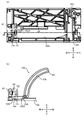
<第2の実施の形態> 第2の実施の形態による丸鋸101を図9乃至図12を用いて説明する。なお、第1の実施の形態と同様の部材等には同じ参照番号を付し、説明を省略する。また第1の実施の形態による丸鋸1を構成する部品や部材と対応する部品・部材には、第1の実施の形態の図面参照番号に100を加算した参照番号を付す。
第2の実施の形態における調整機構105は、バネ154を備える。バネ154はコイルバネであり、コイルの中心には軸52Dが前後に挿通される。バネ154は、ベベルプレート141に埋め込まれるように配置され(図11)、その前端部はストッパプレート151の後面に当接して前方に付勢する。
ワッシャ152Eは、第1の実施の形態におけるワッシャ52Eと異なり、ストッパプレート151より大きな厚みを有する。
ストッパプレート151は、上部に当接部151Aを有する。当接部151Aは前面視において略矩形に形成される。当接部151Aの上端は、前面視または後面視において、サブリンク152の当接部152Gの上端よりも、約5ミリメートル上方に位置する。
ストッパプレート151は、前方に突出した突出部151Eを有し、突出部151Eはサブリンク152と係合する(図9、図11)。突出部151Eがサブリンク152と係合することにより、ストッパプレート151とサブリンク152は、一体に傾動可能である。
ストッパプレート151は、後方の第1位置(図10(a)、図11)と前方の第2位置(図10(b)、図12)との間を移動可能である。第1位置において、ストッパプレート151は、ベベルプレート141と当接する。第2位置において、ストッパプレート151は、サブリンク152と当接する。ストッパプレート151は、バネ154によって前方に付勢されるため、サブベース107を非装着とした状態では第2位置に配置される(図10(b))。
サブリンク152は、図10に示すように、下部が前方に屈曲するように形成される。
サブベース107は、図9に示すように、上方に突出した2つの突起部172を備える。2つの突起部172の上下方向寸法は、ベース4及びサブベース7の厚みより十分長く構成される。なお、サブベース107の厚みは、第1の実施の形態におけるサブベース7と同様、約2.5ミリメートルとする。
サブベース107をベース104に装着した状態を図10(a)及び図11に示す。サブベース107をベース104に装着すると、2つの突起部172は、ベース4の上面から大きく上方に突出する。このとき2つの突起部172は、ストッパプレート151とサブリンク152との間に挿通される。これに伴い、ストッパプレート151は後方へ後退し、第1位置へと配置される。また、2つの突起部172の間にはスプリング154が配置されるようになっており、スプリング154の左右で均等に力を加えられるので、適切にストッパプレート151を後退させることができる。
サブベース107が装着され、これに連動してストッパプレート151が第1位置に配置されると、ソーカバー31の後端部はサブリンク152の当接部152Gと当接可能となる。
サブベース107を非装着とした状態を図10(b)及び図12に示す。非装着状態においては、サブベース107は、バネ154によって前方に付勢され、第2位置に配置される。この場合、ソーカバー31の後端部はストッパプレート151の当接部151Aと当接可能となる。
当接部151Aは、サブリンク152の当接部152Gより5ミリメートル上方に位置する。そのため、非装着状態と装着状態との間で、切断刃6の最大切込み深さは変わらない。即ち、非装着状態に比較して、サブベース107の装着状態における切断刃6は、約2.5ミリメートル分だけ下方に揺動可能となり、サブベース107の厚みを相殺する。したがって最大切込み深さは非装着状態の場合と等しい。
また、切断刃6の最大切込み深さは、ハウジング3が傾動しても維持される。詳細には、ハウジング3が傾動した場合、サブリンク152及びストッパプレート151も一体に傾動する。したがってソーカバー31は、傾動姿勢に関わらず、サブベース107の非装着状態では常にストッパプレート151と当接可能であり、装着状態においてはサブリンク152と常に当接可能である。したがって、切断刃6の最大切込み深さは、傾動時においても維持される。
第2の実施の形態の構成によれば、サブベース107の非装着状態では、ハウジング3が傾動してもストッパプレート151と当接可能であることによって、切断刃6の最大切込み深さを維持することが可能である。また、サブベース107の装着状態では、ハウジング3がサブリンク152と当接することによって最大切込み深さを調整することが可能である。
第2の実施の形態の構成によれば、サブベース107の着脱に連動してストッパプレート151の位置が変更されるため、サブベース107の着脱によって自動的に切断刃6の最大切込み深さが調整される。そのため、ユーザは調整機構105を直接操作することなく、容易に最大切込み深さの調整を行うことが可能となる。またユーザは、最大切込み深さの調整を、忘れることなく確実に実施することができる。
第2の実施の形態の構成によれば、バネ154を備えているため、サブベース107の非装着状態での作業時にストッパプレート151が第2位置から移動することが防止される。そのため、作業時における最大切込み深さの不慮の変動が防止される。
上記のように、第2の実施の形態では、第2位置と第1位置とをストッパプレート151が移動し、ハウジング3の揺動位置及び切断刃6の最大切込み深さの調整を実現した。しかし、本発明は、このような実施の形態に限定されない。本発明は、切断刃6の最大切込み深さの調整を容易に可能にする種々の実施の形態を包含するものである。
<第3の実施の形態> 第3の実施の形態による丸鋸201を図13乃至図14を用いて説明する。なお、第1の実施の形態と同様の部材等には同じ参照番号を付し、説明を省略する。また第1の実施の形態による丸鋸1を構成する部品や部材と対応する部品・部材には、第1の実施の形態の図面参照番号に200を加算した参照番号を付す。
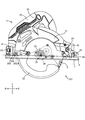
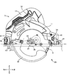
サブベース7を装着した状態の丸鋸201を図13に示し、非装着状態の丸鋸201を図14に示す。第3の実施の形態における調整機構205は、ストッパプレートを備えない。ベベルプレート41の前方には、サブリンク252が配置される。サブリンク252は、他の実施形態と同様に、傾動軸4Aを中心に傾動可能である。またサブリンク252は、第1の実施形態と同様、リンク53を一体に傾動可能に、そして回動可能に支持する。
サブリンク252は、前方に突出する支持部252Hを備える(図13及び図14)。支持部252Hは、略前後方向及び略左右方向に延出した平板状に形成される。
またサブリンク252は、支持部252Hに螺合するネジ255を有する。ネジ255は、支持部252Hに対して軸が略上下方向に延びるように螺合する。ネジ255は、無頭の六角孔付ネジである。ネジ255の頂部には、六角レンチと係合可能な正六角形状の凹部が形成される。ネジ255の頂部は、ソーカバー31の後端部と当接する機能を有する。
ネジ255は、傾動軸4Aまたはベース4に対して近接した第1位置(図13)と、離間した第2位置(図14)との間を移動可能である。
ユーザは、ネジ255を六角レンチ等により回転し、ネジ255を支持部252Hに対して螺進退させることにより、ネジ255を第1位置と第2位置との間で略上下方向に移動させることができる。第1位置と第2位置との間におけるネジ255の移動距離は、約5ミリメートルである。第1位置におけるネジ255の頂部は、第2位置におけるネジ255の頂部よりも、約5ミリメートルだけ傾動軸4Aに近接した位置に配置される。
サブベース7が非装着状態の場合、ネジ255は第2位置に配置される(図14)。一方、サブベース7を装着した場合、ネジ255を第1位置に配置することによって、切断刃6は最大切込み深さを非装着状態における最大切込み深さと等しくすることが可能である(図13)。
以下に詳細に述べる。サブベース7を装着した場合、ソーカバー31の後端部は、第1位置にあるネジ255の頂部と当接する。そのため第2位置のネジ255と当接する場合と比較して、ネジ255は約5ミリメートル下方に揺動することが可能となる。これにより、切断刃6は、約2.5ミリメートル、すなわちサブベース7の厚み分だけ下方に揺動することが可能となる。したがって、切断刃6の最大切込み深さを、サブベース7の装着状態、非装着状態に関わりなく、一定に維持することが可能となる。
ハウジング3を傾動させた場合においても、切断刃6の最大切込み深さは維持される。詳細に述べると、ネジ255はサブリンク252に支持される。サブリンク252は、傾動軸4Aを中心に傾動可能であるため、ネジ255の傾動軸4Aからの距離は、ハウジング3が傾動した場合においても変化しない。したがって、切断刃6の最大切込み深さは、ハウジング3の傾動姿勢に依らず、一定に維持される。
第3の実施の形態の構成によれば、サブリンク252及びネジ255がサブリンクと一体に傾動可能であるため、ハウジング3が傾動した場合でもネジ255とソーカバー31との当接が維持される。また、ネジ255という簡易な構成によって、最大切込み深さを調整する機構が実現される。
<変形例> 上記実施の形態において調整機構5、105、205は、サブリンク52、152、252を備える構成であった。しかし、本発明は必ずしもサブリンクを備える構成とする必要はない。
例えば、調整機構がサブリンクを備えず、リンクによってハウジングの揺動姿勢を調整する機構を備えた丸鋸においても、本発明の実施は可能である。この場合、リンクとベベルプレートとの間にストッパプレートを配置し、第1位置と第2位置との間を移動可能な構成とする。そして、サブベース非装着状態では第2位置のストッパプレートにソーカバーを当接させ、サブベース装着状態ではリンクとソーカバーを当接させることにより、切断刃の最大切込み深さを調整することが可能である。
あるいは、リンクにネジを設け、ネジを第1位置と第2位置との間で移動させることによって、切断刃の最大切込み深さを調整してもよい。
ベースにソーカバーが当接する機構を備えた丸鋸においても、本発明の実施は可能である。この場合、ベースにネジやストッパプレート等の当接部材を配置し、第1位置と第2位置との間を移動させることによって、切断刃の最大切込み深さを調整すればよい。
上記各実施の形態において、ストッパプレート51、151及びネジ255は、本発明の当接部材に相当する。また、バネ54、154は本発明の付勢部材に相当する。
1…丸鋸、2…モータ、3…ハウジング、4…ベース、4A…傾動軸、3A…揺動軸、5…調整機構、6…切断刃、7…サブベース、51…ストッパプレート、52…サブリンク、53…リンク、54…バネ、101…丸鋸、104…ベース、105…調整機構、107…サブベース、141…ベベルプレート、151…ストッパプレート、152…サブリンク、154…バネ、201…丸鋸、251…サブリンク、252…サブリンク、255…ネジ
Claims (9)
- 切断刃を突出させる開口が形成され、切断材上を摺動可能で所定の厚さを有するサブベースが着脱可能なベースと、該切断刃を回転駆動するモータと、該モータを支持し収容するとともに該切断刃を覆い、該切断刃の突出量を変更可能なように該ベースに対して揺動軸の軸心を中心に揺動可能に支持されるハウジングと、該切断刃の突出量を調整して切断材に対する切込み深さを調整する調整機構と、を有し、該調整機構は、該サブベースを該ベースへ装着した装着状態における該切込み深さの最大値と、該サブベースを非装着とした非装着状態における該切込み深さの最大値とが等しくなるように構成されていることを特徴とする丸鋸。
- 該調整機構は、該ハウジングと当接可能であり該ベースに対する位置を第1位置と第2位置との間で変更可能な当接部材を有し、該当接部材の位置の変更によって該ハウジングの該ベースに対する揺動位置を変更し、該切込み深さの最大値を調整可能とすることを特徴とする請求項1に記載の丸鋸。
- 該調整機構は、該切断刃の側面と該ベースとの角度が変更可能となるよう、該揺動軸の軸心と直交する傾動軸を中心に該ベースに対して傾動可能に該ハウジングを支持し、該ハウジングの揺動位置を固定可能に構成される第1調整機構と、該当接部材を備えた第2調整機構とを備え、該ハウジングは、該非装着状態において該第2位置にある該当接部材と当接し、該装着状態において該第1調整機構と当接するとともに該当接部材は該第1位置にあることを特徴とする請求項2に記載の丸鋸。
- 該第1調整機構は、該傾動軸を中心に該ベースに対して傾動可能に支持されるサブリンクと、一体的に傾動可能に該サブリンクと接続され、該ハウジングの揺動位置を固定可能なリンク機構と、を備え、該ハウジングは、該非装着状態において該第2位置にある該当接部材と当接し、該装着状態において該サブリンクと当接するとともに該当接部材は該第1位置にあることを特徴とする請求項3に記載の丸鋸。
- 該サブベースは、該装着状態で該当接部材に当接可能であり、該当接部材は、該サブベースの該ベースへの装着に連動して該第2位置から該第1位置に移動し、該サブベースが該ベースから取外されることに連動して該第1位置から該第2位置に移動することを特徴とする請求項4に記載の丸鋸。
- 該第2調整機構は、該当接部材を該第1位置から該第2位置に向かう方向に付勢する付勢部材をさらに備え、該当接部材は、該ベースに対して回動可能に設けられ、該サブベースを装着するときに該サブベースと当接して回動可能であることを特徴とする請求項5に記載の丸鋸。
- 該第2調整機構は、該サブリンクに対して一体的に傾動可能に接続されていることを特徴とする請求項5に記載の丸鋸。
- 該第2調整機構は、該当接部材を該第1位置から該第2位置に向かう方向に付勢する付勢部材をさらに備え、該当接部材は、該第2位置と該第1位置との間を直線状に移動可能であることを特徴とする請求項7に記載の丸鋸。
- 該調整機構は、第1調整機構と、該当接部材を備えた第2調整機構とを備え、該第1調整機構は、該切断刃の側面と該ベースとの角度が変更可能となるよう、該揺動軸の軸心と直交する傾動軸を中心に該ベースに対して傾動可能に支持されるサブリンクと、一体的に傾動可能に該サブリンクと接続され、該ハウジングの揺動位置を固定可能なリンク機構と、を備え、該第2調整機構は、該傾動軸に対して近接及び離間可能となるように該サブリンクに螺合するネジを有し、該ネジが該当接部材をなすことを特徴とする請求項2に記載の丸鋸。
Priority Applications (1)
| Application Number | Priority Date | Filing Date | Title |
|---|---|---|---|
| JP2018520729A JP6610979B2 (ja) | 2016-05-31 | 2017-04-28 | 丸鋸 |
Applications Claiming Priority (2)
| Application Number | Priority Date | Filing Date | Title |
|---|---|---|---|
| JP2016109531 | 2016-05-31 | ||
| JP2016-109531 | 2016-05-31 |
Publications (1)
| Publication Number | Publication Date |
|---|---|
| WO2017208708A1 true WO2017208708A1 (ja) | 2017-12-07 |
Family
ID=60479378
Family Applications (1)
| Application Number | Title | Priority Date | Filing Date |
|---|---|---|---|
| PCT/JP2017/016967 Ceased WO2017208708A1 (ja) | 2016-05-31 | 2017-04-28 | 丸鋸 |
Country Status (2)
| Country | Link |
|---|---|
| JP (1) | JP6610979B2 (ja) |
| WO (1) | WO2017208708A1 (ja) |
Cited By (2)
| Publication number | Priority date | Publication date | Assignee | Title |
|---|---|---|---|---|
| WO2021259992A2 (en) | 2020-06-25 | 2021-12-30 | Festool Gmbh | Handheld circular saws with improved cutting capabilities |
| JP2023519458A (ja) * | 2019-12-13 | 2023-05-11 | フェスツール ゲーエムベーハー | 筋目入れユニット及びハンドグリップを有する可搬型手持ち鋸機 |
Citations (2)
| Publication number | Priority date | Publication date | Assignee | Title |
|---|---|---|---|---|
| JP2006001148A (ja) * | 2004-06-18 | 2006-01-05 | Hitachi Koki Co Ltd | 携帯用切断工具 |
| JP2015071228A (ja) * | 2013-10-01 | 2015-04-16 | 日立工機株式会社 | 切断工具 |
-
2017
- 2017-04-28 WO PCT/JP2017/016967 patent/WO2017208708A1/ja not_active Ceased
- 2017-04-28 JP JP2018520729A patent/JP6610979B2/ja active Active
Patent Citations (2)
| Publication number | Priority date | Publication date | Assignee | Title |
|---|---|---|---|---|
| JP2006001148A (ja) * | 2004-06-18 | 2006-01-05 | Hitachi Koki Co Ltd | 携帯用切断工具 |
| JP2015071228A (ja) * | 2013-10-01 | 2015-04-16 | 日立工機株式会社 | 切断工具 |
Cited By (6)
| Publication number | Priority date | Publication date | Assignee | Title |
|---|---|---|---|---|
| JP2023519458A (ja) * | 2019-12-13 | 2023-05-11 | フェスツール ゲーエムベーハー | 筋目入れユニット及びハンドグリップを有する可搬型手持ち鋸機 |
| JP7665535B2 (ja) | 2019-12-13 | 2025-04-21 | フェスツール ゲーエムベーハー | 筋目入れユニット及びハンドグリップを有する可搬型手持ち鋸機 |
| US12459157B2 (en) | 2019-12-13 | 2025-11-04 | Festool Gmbh | Mobile hand-held sawing machine having pre-cutting assembly and grip |
| WO2021259992A2 (en) | 2020-06-25 | 2021-12-30 | Festool Gmbh | Handheld circular saws with improved cutting capabilities |
| WO2021259992A3 (en) * | 2020-06-25 | 2022-02-17 | Festool Gmbh | Handheld circular saws with improved cutting capabilities |
| EP4684899A3 (en) * | 2020-06-25 | 2026-03-25 | Festool GmbH | Handheld circular saws with improved cutting capabilities |
Also Published As
| Publication number | Publication date |
|---|---|
| JPWO2017208708A1 (ja) | 2019-01-17 |
| JP6610979B2 (ja) | 2019-11-27 |
Similar Documents
| Publication | Publication Date | Title |
|---|---|---|
| EP2149438B1 (en) | Portable cutting tool | |
| JP3710683B2 (ja) | 携帯マルノコ | |
| JP4780524B2 (ja) | 携帯用切断機 | |
| JP7249797B2 (ja) | 携帯用加工機 | |
| JP2007223133A5 (ja) | ||
| JP6610979B2 (ja) | 丸鋸 | |
| US8677872B2 (en) | Sawing machine having a miter angle adjustment assembly | |
| JP7352335B2 (ja) | 電動工具 | |
| JP5439868B2 (ja) | 携帯用切断機 | |
| JP7103002B2 (ja) | 切断機 | |
| JP6274522B2 (ja) | 切断機 | |
| JP2025013009A (ja) | 携帯用切断機 | |
| JP7290557B2 (ja) | レバー装置 | |
| JP6946152B2 (ja) | 平行定規および携帯用加工機 | |
| JP4446285B2 (ja) | 携帯用切断機 | |
| JP2007175957A (ja) | 電動切削工具 | |
| JP2010076059A (ja) | 携帯用切断機 | |
| JP2009132096A (ja) | 卓上切断機 | |
| JP5582929B2 (ja) | 切断機 | |
| JP5741120B2 (ja) | 携帯用切断機 | |
| JP2016097520A (ja) | 電動工具 | |
| JP5514678B2 (ja) | 丸鋸 | |
| JP2006159786A (ja) | 切断機 | |
| JP2024121991A (ja) | 作業機 | |
| JP5793214B2 (ja) | 丸鋸 |
Legal Events
| Date | Code | Title | Description |
|---|---|---|---|
| WWE | Wipo information: entry into national phase |
Ref document number: 2018520729 Country of ref document: JP |
|
| 121 | Ep: the epo has been informed by wipo that ep was designated in this application |
Ref document number: 17806267 Country of ref document: EP Kind code of ref document: A1 |
|
| NENP | Non-entry into the national phase |
Ref country code: DE |
|
| 122 | Ep: pct application non-entry in european phase |
Ref document number: 17806267 Country of ref document: EP Kind code of ref document: A1 |