WO2017208634A1 - 電子キー - Google Patents
電子キー Download PDFInfo
- Publication number
- WO2017208634A1 WO2017208634A1 PCT/JP2017/014905 JP2017014905W WO2017208634A1 WO 2017208634 A1 WO2017208634 A1 WO 2017208634A1 JP 2017014905 W JP2017014905 W JP 2017014905W WO 2017208634 A1 WO2017208634 A1 WO 2017208634A1
- Authority
- WO
- WIPO (PCT)
- Prior art keywords
- key
- engagement plane
- plane
- case
- side engagement
- Prior art date
- Legal status (The legal status is an assumption and is not a legal conclusion. Google has not performed a legal analysis and makes no representation as to the accuracy of the status listed.)
- Ceased
Links
Images





Classifications
-
- E—FIXED CONSTRUCTIONS
- E05—LOCKS; KEYS; WINDOW OR DOOR FITTINGS; SAFES
- E05B—LOCKS; ACCESSORIES THEREFOR; HANDCUFFS
- E05B19/00—Keys; Accessories therefor
- E05B19/0082—Keys or shanks being removably stored in a larger object, e.g. a remote control or a key fob
-
- B—PERFORMING OPERATIONS; TRANSPORTING
- B60—VEHICLES IN GENERAL
- B60R—VEHICLES, VEHICLE FITTINGS, OR VEHICLE PARTS, NOT OTHERWISE PROVIDED FOR
- B60R25/00—Fittings or systems for preventing or indicating unauthorised use or theft of vehicles
- B60R25/20—Means to switch the anti-theft system on or off
- B60R25/24—Means to switch the anti-theft system on or off using electronic identifiers containing a code not memorised by the user
-
- E—FIXED CONSTRUCTIONS
- E05—LOCKS; KEYS; WINDOW OR DOOR FITTINGS; SAFES
- E05B—LOCKS; ACCESSORIES THEREFOR; HANDCUFFS
- E05B19/00—Keys; Accessories therefor
- E05B19/04—Construction of the bow or head of the key; Attaching the bow to the shank
- E05B19/046—Construction of the bow or head of the key; Attaching the bow to the shank the shank being slidingly mounted on the bow, e.g. for storage
-
- G—PHYSICS
- G07—CHECKING-DEVICES
- G07C—TIME OR ATTENDANCE REGISTERS; REGISTERING OR INDICATING THE WORKING OF MACHINES; GENERATING RANDOM NUMBERS; VOTING OR LOTTERY APPARATUS; ARRANGEMENTS, SYSTEMS OR APPARATUS FOR CHECKING NOT PROVIDED FOR ELSEWHERE
- G07C9/00—Individual registration on entry or exit
- G07C9/00174—Electronically operated locks; Circuits therefor; Nonmechanical keys therefor, e.g. passive or active electrical keys or other data carriers without mechanical keys
- G07C9/00944—Details of construction or manufacture
-
- G—PHYSICS
- G07—CHECKING-DEVICES
- G07C—TIME OR ATTENDANCE REGISTERS; REGISTERING OR INDICATING THE WORKING OF MACHINES; GENERATING RANDOM NUMBERS; VOTING OR LOTTERY APPARATUS; ARRANGEMENTS, SYSTEMS OR APPARATUS FOR CHECKING NOT PROVIDED FOR ELSEWHERE
- G07C9/00—Individual registration on entry or exit
- G07C9/00174—Electronically operated locks; Circuits therefor; Nonmechanical keys therefor, e.g. passive or active electrical keys or other data carriers without mechanical keys
- G07C9/00944—Details of construction or manufacture
- G07C2009/00952—Electronic keys comprising a mechanical key within their housing, e.g. extractable or retractable emergency key
-
- G—PHYSICS
- G07—CHECKING-DEVICES
- G07C—TIME OR ATTENDANCE REGISTERS; REGISTERING OR INDICATING THE WORKING OF MACHINES; GENERATING RANDOM NUMBERS; VOTING OR LOTTERY APPARATUS; ARRANGEMENTS, SYSTEMS OR APPARATUS FOR CHECKING NOT PROVIDED FOR ELSEWHERE
- G07C9/00—Individual registration on entry or exit
- G07C9/00174—Electronically operated locks; Circuits therefor; Nonmechanical keys therefor, e.g. passive or active electrical keys or other data carriers without mechanical keys
- G07C2009/00968—Electronically operated locks; Circuits therefor; Nonmechanical keys therefor, e.g. passive or active electrical keys or other data carriers without mechanical keys shape of the data carrier
- G07C2009/00984—Electronically operated locks; Circuits therefor; Nonmechanical keys therefor, e.g. passive or active electrical keys or other data carriers without mechanical keys shape of the data carrier fob
Definitions
- This disclosure relates to an electronic key with a mechanical key used in a remote control system for opening and closing a door.
- the electronic key may be housed in a case so that the door can be opened and closed even when the battery runs out.
- a mechanical key is provided with a rod-shaped part, and this rod-shaped part is accommodated in the case of an electronic key.
- the case often stores the mechanical key so that it can be inserted and removed in the axial direction of the rod-shaped portion.
- the case is provided with a lock mechanism for suppressing the mechanical key from falling off the case.
- the lock mechanism of Patent Document 1 includes a slide portion. In a locked state in which the emergency key, which is a mechanical key, is prevented from falling out of the case, the slide portion fits into the recessed portion of the emergency key.
- the slope portion formed at the distal end portion of the slide portion engages with the inclined surface formed at the opening of the recess portion included in the emergency key.
- Patent Document 1 in a locked state, the lock mechanism side surface and the emergency key side surface that are engaged with each other are inclined with respect to the axial direction of the bar portion of the emergency key. Since the two surfaces that are engaged with each other are inclined with respect to the axial direction of the bar portion of the emergency key, the emergency key can move to the axial direction of the bar portion of the emergency key to some extent even in the locked state. Therefore, even if the emergency key does not enter the innermost position of the case due to the presence of dust or the like, the lock mechanism can lock the emergency key.
- Patent Document 1 can prevent the emergency key from falling out of the case even if the emergency key is not sufficiently inserted into the case due to the presence of dust or the like.
- the emergency key is pulled even in the locked state.
- a force in a direction in which the slide portion is separated from the rod-like portion acts on the slide portion from the emergency key.
- the slide portion is moved in a direction away from the rod-shaped portion, so that the flat surface portion formed at the tip portion of the slide portion comes into contact with the contact surface formed in the recess portion of the emergency key.
- the emergency key moves in the axial direction of the rod-shaped part.
- Patent Document 1 when the emergency key is pulled even in the locked state, there is a possibility that the emergency key is rattled by the length of the slope portion in the axial direction of the bar portion of the emergency key.
- the present disclosure has been made based on this circumstance, and the purpose of the present disclosure is to prevent the mechanical key from being rattled when the mechanical key is pulled while the mechanical key is sufficiently in the case due to dust or the like.
- An object of the present invention is to provide an electronic key that can prevent a mechanical key from falling out of a case even when it is not inserted into the case.
- An electronic key includes a mechanical key having a rod-shaped portion, a case that accommodates the mechanical key so that the mechanical key can be inserted and removed in an axial direction of the rod-shaped portion, and the case is provided.
- a mechanical key is a key side engagement plane that is a plane perpendicular to the axial direction of the rod-like portion in a locked state in which the mechanical key is suppressed from falling out of the case by the suppression member.
- the restraining member is a plane perpendicular to the axial direction of the rod-shaped portion in the locked state, and includes a lock side engagement plane that engages with the key side engagement plane, and the key side engagement plane and the lock side engagement At least one of the planes has a different position in the axial direction of the bar-shaped portion of the mechanical key and is engaged with the other of the key side engagement plane and the lock side engagement plane.
- At least one of the key-side engagement plane and the lock-side engagement plane includes a plurality of engagement planes having different positions in the axial direction (hereinafter referred to as axial positions) of the bar-shaped portion of the mechanical key.
- the plurality of engagement planes can be engaged with the other engagement plane.
- the plurality of engagement planes have different axial positions, and the plurality of engagement planes can be engaged with the other engagement plane.
- the mating plane may engage the other engagement plane. Therefore, even when the mechanical key is not completely inserted due to dust or the like, the mechanical key can be prevented from falling off.
- the lock-side engagement plane is the rod-shaped portion. Therefore, the mechanical key does not move in the direction away from the case. Therefore, rattling when the mechanical key is pulled can be suppressed.
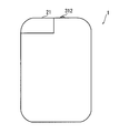
- FIG. 1 is a plan view of the electronic key according to the first embodiment of the present disclosure.
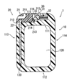
- FIG. 2 is a cross-sectional view of the electronic key of FIG. 1 cut at the center in the thickness direction.
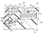
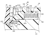
- FIG. 3 is an enlarged cross-sectional view of the vicinity of the lock portion of FIG.
- FIG. 4 is a diagram illustrating a state in which the mechanical key is being inserted
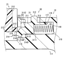
- FIG. 5 is a diagram illustrating a state in which the mechanical key is inserted and the locked state is first set.
- FIG. 6 is a diagram showing that a locked state is possible even if there is a foreign object, FIG.
- FIG. 7 is a cross-sectional view of the electronic key according to the second embodiment of the present disclosure.
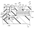
- FIG. 8 is an enlarged cross-sectional view of the vicinity of the lock portion of FIG.
- FIG. 9 is an enlarged cross-sectional view of the vicinity of the lock portion in a state where the mechanical key is completely stored in the case in the second embodiment.
- FIG. 10 is a cross-sectional view of an electronic key according to a third embodiment of the present disclosure.
- FIG. 11 is an enlarged cross-sectional view of the vicinity of the lock portion of FIG.
- FIG. 12 is a diagram illustrating a state in which the mechanical key is inserted and the locked state is first set.
- FIG. 13 is a view showing the vicinity of the grip portion in the state of FIG.
- FIG. 14 is an enlarged cross-sectional view of the vicinity of the lock portion of the electronic key according to the fourth embodiment of the present disclosure.
- FIG. 15 is a diagram illustrating a state in which the mechanical key is inserted and the locked state
- FIG. 1 is a plan view of the electronic key 1 of the first embodiment.
- the electronic key 1 transmits a signal for switching the door lock of the vehicle from the unlocked state to the locked state, or vice versa, to a receiver provided in the vehicle.
- a part of the structure such as a switch portion of the electronic key 1 is omitted.
- the planar shape of the electronic key 1 is a quadrangular shape with rounded corners.
- the planar shape of the case 10 is a shape in which one corner portion is missing, and the grip portion 21 of the mechanical key 20 is located in the missing portion. Therefore, the grip part 21 is exposed from the case 10.
- the protrusion 312 of the release hook 31 protrudes from the case 10 adjacent to the grip part 21.
- the thickness of the electronic key 1 is shorter than the length in the vertical direction and the length in the horizontal direction shown in FIG. That is, the electronic key 1 has a flat shape.
- FIG. 2 shows the internal structure of the electronic key 1.
- the case 10 is made of resin, and includes short wall portions 111 and 112 that are relatively short sides, and long wall portions 113 and 114 that are longer than the short wall portions 111 and 112.
- An electronic component is accommodated in a space formed by the short wall portions 111 and 112, the long wall portions 113 and 114, and the bottom portion 120 and a lid portion (not shown) facing the bottom portion 120.
- electronic components are omitted.
- the mechanical key 20 includes a grip portion 21 and a rod-shaped portion 22.
- the grip portion 21 is made of the same resin as the case 10.
- a through hole 211 is formed in the grip portion 21, and a key holder ring or the like is inserted into the through hole 211.
- the rod-shaped portion 22 is made of metal and has at least one of a keyway and a key mountain.
- the base of the rod-like part 22 is inserted into the grip part 21.
- the door lock of the vehicle can be switched from the unlocked state to the locked state, or from the locked state to the unlocked state by inserting the rod-like portion 22 of the mechanical key 20 into the key cylinder of the vehicle door.
- a housing hole 130 for housing the rod-like portion 22 of the mechanical key 20 is formed in the long wall portion 113 of the case 10.
- the state where the rod-like portion 22 of the mechanical key 20 is accommodated in the accommodation hole 130 is the state where the mechanical key 20 is accommodated in the case 10.
- the planar case contact surface 212 which is the surface of the grip portion 21 on the side where the rod-like portion 22 protrudes is opposed to the grip of the case 10. Contact surface 115.
- the lock part 30 is also accommodated in the case 10.
- the lock part 30 is accommodated in a lock part accommodating space 116 formed in the short wall part 111 of the case 10.
- the grip portion 21 has a protrusion 213 that protrudes toward the lock portion 30 at the end on the case contact surface 212 side.
- An outer surface of the case of the protrusion 213 is an engagement plane 214 that engages with the lock portion 30.
- the engagement plane 214 corresponds to the key side engagement plane.
- the engagement plane 214 is a plane perpendicular to the axial direction of the rod-like portion 22 of the mechanical key 20, in other words, the insertion / removal direction of the mechanical key 20.
- the key insertion / removal direction in the following description means the insertion / removal direction of the mechanical key 20.
- the lock part 30 includes a release hook 31, a spring 32, and a stopper part 33 formed on the case 10.
- the release hook 31 suppresses the grip portion 21 of the mechanical key 20 from moving in a direction away from the case 10.
- the state in which the release hook 31 suppresses the grip portion 21 of the mechanical key 20 from moving in a direction away from the case 10 is a locked state.
- the release hook 31 is also made of resin.
- the release hook 31 corresponding to the suppressing member includes a central portion 311, a protruding portion 312, an outer guide portion 313, and a tip portion 314.
- the central portion 311 is a central portion of the release hook 31 and includes a spring contact surface 3111.
- One end of the spring 32 is in contact with the spring contact surface 3111.
- the other end of the spring 32 is supported by a support surface 119 that is formed on the case 10 and that faces the spring contact surface 3111.
- the release hook 31 is urged by the spring 32 in a direction approaching the grip portion 21.
- the spring 32 is a compression coil spring. 2 to 4, the spring 32 is shown in a simplified manner.
- the central portion 311 includes a stopper contact surface 3112 on the side opposite to the spring contact surface 3111.
- the stopper contact surface 3112 contacts a hook contact surface 331 formed on the stopper portion 33. The contact between the stopper contact surface 3112 and the hook contact surface 331 prevents the release hook 31 from moving further in the direction of the grip portion 21.
- the protruding portion 312 is connected to the central portion 311 in the vicinity of the spring contact surface 3111 of the central portion 311 and protrudes from the central portion 311 toward the case outer side.
- the protruding portion 312 protrudes from the case 10 so that it can be operated by the user.
- the protruding portion 312 is moved in a direction against the urging force of the spring 32, the locked state is released, and the mechanical key 20 is released. It can be extracted from the case 10.
- the outer guide portion 313 protrudes from the spring contact surface 3111 of the central portion 311 toward the support surface 119 of the case 10.
- the outer guide portion 313 moves while being in contact with the outer guide surface 117 formed on the case 10.
- the bottom surface 3113 of the central portion 311 is in contact with the inner guide surface 118 formed on the case 10.
- the front end portion 314 protrudes from the center portion 311 in the direction of the grip portion 21 that is opposite to the spring contact surface 3111.
- the tip 314 includes an outer inclined surface 3141, a first engaging plane 3142, a second engaging plane 3143, and an inner inclined surface 3144.
- the outer inclined surface 3141 is inclined such that the closer to the grip portion 21, the closer the position in the key insertion / removal direction is to the case contact surface 212.
- the first engagement plane 3142 and the second engagement plane 3143 are planes perpendicular to the key insertion / removal direction.
- the first engagement plane 3142 is formed closer to the distal end side of the release hook 31 than the second engagement plane 3143.
- the first engagement plane 3142 is formed closer to the hook-facing side surface 215 that is the side surface on the release hook 31 side in the grip portion 21 than the second engagement plane 3143.
- the first engagement plane 3142 and the second engagement plane 3143 are also different in the key insertion / removal position.
- the first engagement plane 3142 is located in the key extraction direction (that is, the outer peripheral side of the case 10) in the key insertion / removal direction with respect to the second engagement plane 3143.
- the first engagement plane 3142 and the second engagement plane 3143 are both lock-side engagement planes, and there is a step in the key insertion / removal direction between the first engagement plane 3142 and the second engagement plane 3143. Therefore, the lock side engagement plane of the present embodiment has a stepped plane structure.
- the inner inclined surface 3144 corresponding to the connection surface is a plane connecting the first engagement plane 3142 and the second engagement plane 3143. Contrary to the outer inclined surface 3141, the inner inclined surface 3144 is inclined so that the position in the key insertion / removal direction is farther from the case contact surface 212 as it is closer to the hook-facing side surface 215 of the grip portion 21.
- the positions of the engagement plane 214 of the grip portion 21 and the first engagement plane 3142 formed on the distal end portion 314 of the release hook 31 in the key insertion / removal direction coincide. . Since the release hook 31 is biased in the direction of the grip portion 21 by the spring 32, the release hook 31 is directed in the direction of the grip portion 21 when the positions of the engagement plane 214 and the first engagement plane 3142 in the key insertion / removal direction match. Move to. As a result, as shown in FIG. 5, the engagement plane 214 and the first engagement plane 3142 come into contact with each other, so that the mechanical key 20 is prevented from falling off the case 10.
- the release hook 31 is further moved from the position in FIG. 5 toward the grip portion 21 to be in the state shown in FIG.
- the second engagement plane 3143 of the release hook 31 and the engagement plane 214 of the grip portion 21 are in contact with each other.
- the state shown in FIG. 3 is also a locked state. In the state shown in FIG. 3, unlike the state shown in FIG. 5, the tip of the grip portion 21 does not protrude from the case 10. Improves.
- the release hook 31 includes the first engagement plane 3142 and the second engagement plane 3143 that can be engaged with the engagement plane 214 of the grip portion 21.
- the first engagement plane 3142 and the second engagement plane 3143 have different positions in the key insertion / removal direction, and the first engagement plane 3142 and the second engagement plane 3143 are both of the grip portion 21. Engageable with the engagement plane 214.
- the engagement plane 214, the first engagement plane 3142, and the second engagement plane 3143 are planes perpendicular to the key insertion / removal direction. Therefore, when the mechanical key 20 is pulled in the key extracting direction in the locked state, the release hook 31 moves in a direction away from the rod-like portion 22 of the mechanical key 20, and thereby the mechanical key 20 is removed in the direction of detaching from the case 10. None move. Therefore, rattling when the mechanical key 20 is pulled can also be suppressed.
- an inner inclined surface 3144 is provided between the first engagement plane 3142 and the second engagement plane 3143. Therefore, it is necessary when inserting the mechanical key 20 into the case 10 from the state where the engagement plane 214 of the grip portion 21 is engaged with the first engagement plane 3142 to the state where it is engaged with the second engagement plane 3143. Less power.
- the electronic key 1A of the second embodiment has the configuration shown in FIG.
- the configuration of the protrusion 213A provided in the grip portion 21A of the mechanical key 20A and the configuration of the tip portion 314A of the release hook 31A provided in the lock portion 30A are the same as the projection 213 and the tip of the first embodiment, respectively. This is different from the part 314.
- a configuration different from those of the first embodiment will be described with reference to FIG.
- the protrusion 213A provided in the grip portion 21A protrudes in the direction of the lock portion 30A at the end of the grip portion 21A on the case contact surface 212 side.
- a first engagement plane 216 and a second engagement plane 217 that engage with the lock portion 30 are formed on the outer surface of the case of the protrusion 213A.
- the first engagement plane 216 and the second engagement plane 217 are both planes perpendicular to the key insertion / removal direction.
- the first engagement plane 216 is formed closer to the release hook 31A than the second engagement plane 217.
- the first engagement plane 216 is formed on the outer side of the grip portion 21 ⁇ / b> A, that is, at a position farther from the hook-facing side surface 215 than the second engagement plane 217.
- first engagement plane 216 and the second engagement plane 217 are different in the key insertion / removal position.
- the first engagement plane 216 is positioned more in the key insertion direction in the key insertion / removal direction than the second engagement plane 217.
- the first engagement plane 216 and the second engagement plane 217 are both key side engagement planes, and there is a step in the key insertion / removal direction between the first engagement plane 216 and the second engagement plane 217. Therefore, in the second embodiment, the key side engagement plane has a stepped plane structure.
- the first engagement plane 216 and the second engagement plane 217 are connected by a connection surface 218.
- the connection surface 218 is a plane having an inclination in which the position in the key insertion / removal direction is farther from the case contact surface 212 as it is closer to the hook-facing side surface 215.
- the distal end portion 314 of the release hook 31 of the first embodiment includes a first engagement plane 3142 and a second engagement plane 3143 as surfaces that engage with the engagement plane 214 formed on the protrusion 213 of the grip portion 21. It was.
- the distal end portion 314A of the release hook 31A has one engagement plane 3145 as a surface that engages with the first engagement plane 216 and the second engagement plane 217 formed on the protrusion 213A of the grip portion 21A. Is provided.
- the engagement plane 3145 corresponds to the lock side engagement plane.
- the release hook 31A corresponds to a suppressing member.
- the engagement plane 3145 has the same position in the key insertion / removal direction as the second engagement plane 3143 of the first embodiment. Further, the area of the engagement plane 3145 is such that the area of the first engagement plane 3142 of the first embodiment, the area of the second engagement plane 3143, and the inner inclined surface 3144 include the second engagement plane 3143. The sum of the projected areas is the same as the sum of the areas.
- FIG. 10 is a diagram corresponding to FIG. 2 in the first embodiment.
- the case 10B includes short wall portions 111B and 112B and long wall portions 113B and 114B longer than the short wall portions 111B and 112B.
- Electronic components are housed in a space formed by the short wall portions 111B and 112B, the long wall portions 113B and 114B, and the bottom portion 120 and a lid portion (not shown) facing the bottom portion 120.
- electronic components are omitted.
- the mechanical key 20B includes a grip portion 21B and a rod-shaped portion 22B.
- the grip portion 21B is made of resin, and the rod-like portion 22B is made of metal.
- the base of the rod-like portion 22B is inserted into the grip portion 21B.
- a housing hole 130B for housing the rod-like portion 22B of the mechanical key 20B is formed from the short wall portion 112B to the long wall portion 113B of the case 10B.
- the accommodation hole 130B has an opening on the end surface of the short wall portion 112B.
- the state where the rod-like portion 22B of the mechanical key 20B is accommodated in the accommodation hole 130B is the state where the mechanical key 20B is accommodated in the case 10B.
- the grip portion 21B protrudes from the case 10B even when the mechanical key 20B is accommodated in the case 10B.
- the case contact surface 212B that is the surface of the grip portion 21 on the side from which the rod-like portion 22 protrudes contacts the short wall portion 112B.
- the long wall portion 113B of the case 10B has a lock portion accommodation space 116B connected to the accommodation hole 130B.
- the lock portion 30B is accommodated in the lock portion accommodation space 116B.
- the lock portion 30B includes a release hook 31B corresponding to a suppressing member and a spring 32B.
- the release hook 31B according to the third embodiment is a swing type, and is located near the center of the release hook 31B and can swing about a shaft 35 that functions as a swing shaft.
- the spring 32B is a torsion coil spring. One end of the spring 32B is in contact with the bottom of the lock portion accommodating space 116B, and the other end is accommodated in the accommodating portion 312B formed on the back surface 311B of the release hook 31B. A coil portion (not shown) of the spring 32 ⁇ / b> B is wound around the shaft 35.
- the accommodating portion 312B is located at the end of the release hook 31B opposite to the grip portion 21B in the key insertion / removal direction. Since the end of the spring 32B is accommodated in the accommodating portion 312B and the coil portion of the spring 32B is wound around the shaft 35, the accommodating portion 312B of the release hook 31B is separated from the bottom surface of the lock portion accommodating space 116B. The release hook 31B is biased.
- a convex portion 313B is formed at the end of the release hook 31B opposite to the housing portion 312B.
- the convex portion 313B protrudes from the base portion 314B of the release hook 31B toward the bottom surface of the lock portion accommodation space 116B.
- the convex portion 313B includes an inclined surface 315B, a first engagement plane 316B, a second engagement plane 317B, and a connection surface 318B.
- the inclined surface 315B is a surface that is inclined with respect to the key insertion / removal direction regardless of the swing angle of the release hook 31B, and the inclination direction is such that the lock insertion space 116B increases as the key insertion / removal direction becomes the key insertion direction. It is the direction which goes to the bottom.
- the inclination is an angle that is neither horizontal nor vertical.
- the first engagement plane 316B and the second engagement plane 317B are both planes that engage with the engagement plane 221B formed at the tip of the rod-like portion 22B of the mechanical key 20B.
- the angles of the first engagement plane 316B and the second engagement plane 317B with respect to the axial direction of the rod-shaped portion 22B of the mechanical key 20B vary depending on the rotation angle of the release hook 31B.
- both the first engagement plane 316B and the second engagement plane 317B are perpendicular to the key insertion / removal direction at the position where the engagement plane 221B is engaged.
- the first engagement plane 316B is formed closer to the base 314B of the release hook 31B than the second engagement plane 317B. Further, the first engagement plane 316B and the second engagement plane 317B have different positions in the key insertion / removal direction. The first engagement plane 316B is formed closer to the key extraction direction in the key insertion / removal direction than the second engagement plane 317B, that is, closer to the opening on the end face side of the short wall portion 112B in the accommodation hole 130B.
- the first engagement plane 316B and the second engagement plane 317B are both hook-side engagement planes, and there is a step in the key insertion / removal direction between the first engagement plane 316B and the second engagement plane 317B.
- the hook side engagement plane has a stepped plane structure.
- connection surface 318B connects the first engagement plane 316B and the second engagement plane 317B.
- a through-hole 222B that penetrates the rod-shaped portion 22B in a direction orthogonal to the axis is formed at the tip of the rod-shaped portion 22B of the mechanical key 20B, and a part of the side surface of the through-hole 222B is an engagement plane 221B.
- the engagement plane 221B corresponds to the key-side engagement plane, and is perpendicular to the key insertion / removal direction, that is, the axial direction of the rod-shaped portion 22B, and is formed over the entire thickness direction of the rod-shaped portion 22B.
- the tip of the rod-like portion 22B of the mechanical key 20B can pass the tip of the convex portion 313B.
- the positions of the engagement plane 221B formed at the tip of the rod-shaped portion 22B and the first engagement plane 316B formed at the release hook 31B in the key insertion / removal direction match. To do.
- the engagement plane 221B and the first engagement plane 316B are engaged with each other, so that the grip portion 21B of the mechanical key 20B is restrained from moving away from the case 10B. It becomes a locked state.
- FIG. 13 shows the vicinity of the grip portion 21B in the state shown in FIG. In a state where the engagement plane 221B and the first engagement plane 316B are engaged, as shown in FIG. 13, there is a gap between the case contact surface 212B of the grip portion 21B and the short wall portion 112B. Therefore, even if foreign matter 4 such as dust exists between the case contact surface 212 and the short wall portion 112B, the locked state can be achieved.
- the second engagement plane 317B and the engagement plane 221B are in contact with each other.
- the state shown in FIG. 11 is also a locked state.
- the surface 319B of the release hook 31B does not protrude from the long wall portion 113B of the case 10B. To do.
- FIG. 14 is a diagram corresponding to FIG. 11, and the configuration of the portion not shown in FIG. 14 is the same as that of the electronic key 1B of the third embodiment.
- the configuration of the tip portion of the rod-shaped portion 22C of the mechanical key 20C and the configuration of the convex portion 313C of the release hook 31C included in the lock portion 30C are respectively the rod-shaped portion 22B and the convex portion 313B of the third embodiment. Is different.
- the release hook 31C corresponds to a suppressing member.
- a through hole 222C is formed at the same position as the through hole 222B of the third embodiment.
- one engagement plane 221B is formed in the through hole 222B.
- a first engagement plane 223C, a second engagement plane 224C, and a connection surface 225C are formed instead of the engagement plane 221B.
- the first engagement plane 223C and the second engagement plane 224C are both planes that engage with the engagement plane 317C formed on the convex portion 313C.
- Each of the first engagement plane 223C and the second engagement plane 224C is a plane perpendicular to the key insertion / removal direction, that is, a plane perpendicular to the axial direction of the rod-like portion 22C.
- the first engagement plane 223C is formed closer to the base 314B of the release hook 31C than the second engagement plane 224C in a state where the mechanical key 20C is inserted into the case 10B.
- the first engagement plane 223C and the second engagement plane 224C are also different in the key insertion / removal direction.
- the first engagement plane 223C is formed closer to the key insertion direction in the key insertion / removal direction than the second engagement plane 224C, that is, closer to the tip of the rod-like portion 22C of the mechanical key 20C.
- the first engagement plane 223C and the second engagement plane 224C are both key-side engagement planes, and there is a step in the key insertion / removal direction between the first engagement plane 223C and the second engagement plane 224C.
- the key side engagement plane has a stepped plane structure.
- connection surface 225C is a plane that connects the first engagement plane 316B and the second engagement plane 317B, and is a plane that is inclined closer to the base portion 314B of the release hook 31C as it is closer to the tip of the rod-shaped portion 22C. .
- An engagement flat surface 317C is formed on the convex portion 313C of the release hook 31C.
- This engagement plane 317C is provided in place of the first engagement plane 316B, the second engagement plane 317B, and the connection surface 318 formed on the convex portion 313B of the third embodiment.
- the engagement plane 317C corresponds to the lock side engagement plane.
- the second engagement plane 224C and the engagement plane 317C are in contact with each other.
- the state shown in FIG. 14 is also a locked state.
- one of the key side engagement plane and the lock side engagement plane has only one plane.
- both the key side engagement plane and the lock side engagement plane may include a plurality of engagement planes.
- the engagement plane on the side having the stepped plane structure has two engagement planes, but may have three or more engagement planes. Good.
Landscapes
- Engineering & Computer Science (AREA)
- Mechanical Engineering (AREA)
- Manufacturing & Machinery (AREA)
- Physics & Mathematics (AREA)
- General Physics & Mathematics (AREA)
- Lock And Its Accessories (AREA)
Abstract
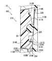
メカニカルキーと、メカニカルキーを収納するケース(10)と、ケース(10)に設けられ、メカニカルキーがケース(10)から抜け落ちることを抑制する抑制部材(31)とを備え、メカニカルキーは、抑制部材(31)によりケース(10)から抜け落ちることが抑制されているロック状態において棒状部の軸方向に垂直な平面である係合平面(214)を備え、抑制部材(31)は、メカニカルキーの棒状部の軸方向に垂直な平面であって、係合平面(214)と係合する第1係合平面(3142)、第2係合平面(3143)を備え、第1係合平面(3142)、第2係合平面(3143)は、メカニカルキーの棒状部の軸方向における位置が異なる段差平面構造になっている。
Description
本出願は、2016年5月31日に出願された日本特許出願番号2016-108713号に基づくもので、ここにその記載内容を援用する。
本開示は、ドアを開閉する遠隔制御システム等に用いられる、メカニカルキー付きの電子キーに関する。
電子キーは、電池が切れた場合でも、ドアの開閉等ができるようにするためにメカニカルキーがケースに収容されていることがある。一般的に、メカニカルキーは、棒状部を備え、この棒状部が電子キーのケースに収容される。
特許文献1に開示されているように、ケースは、メカニカルキーを、その棒状部の軸方向に抜き差し可能に収納することが多い。そして、ケースには、メカニカルキーがケースから抜け落ちることを抑制するためのロック機構が備えられる。
特許文献1のロック機構は、スライド部を備えている。スライド部が、メカニカルキーであるエマージェンシーキーがケースから抜け落ちることを抑制しているロック状態では、スライド部の先端部が、エマージェンシーキーが備える窪み部に嵌り込む。
より詳しくは、上記ロック状態では、スライド部の先端部に形成されたスロープ部が、エマージェンシーキーが備える窪み部の開口に形成された傾斜面と係合する。
特許文献1では、ロック状態で、互いに係合するロック機構側の面とエマージェンシーキー側の面は、エマージェンシーキーの棒状部の軸方向に対して傾斜している。互いに係合する2つの面が、エマージェンシーキーの棒状部の軸方向に対して傾斜しているので、エマージェンシーキーはロック状態でも、ある程度、エマージェンシーキーの棒状部の軸方向に移動可能である。そのため、ゴミ等の存在により、エマージェンシーキーがケースの最も奥の位置まで入らないとしても、ロック機構はエマージェンシーキーをロック状態とすることができる。
したがって、特許文献1の機構では、ゴミ等の存在により、エマージェンシーキーがケースに十分に差し込まれていなくても、エマージェンシーキーがケースから抜け落ちることを抑制できる。
しかし、ロック状態で、互いに係合するロック機構側の面とエマージェンシーキー側の面が、エマージェンシーキーの棒状部の軸方向に対して傾斜していると、ロック状態でも、エマージェンシーキーが引っ張られた場合に、スライド部が棒状部から離隔する方向への力が、エマージェンシーキーからスライド部に作用する。これにより、スライド部は棒状部から離隔する方向に移動させられるので、スライド部の先端部に形成された平面部が、エマージェンシーキーの窪み部に形成された当接面と当接する状態となるまで、エマージェンシーキーは、棒状部の軸方向に移動する。
つまり、特許文献1では、ロック状態でも、エマージェンシーキーが引っ張られると、エマージェンシーキーの棒状部の軸方向におけるスロープ部の長さ分だけ、エマージェンシーキーにがたつきが生じる可能性がある。
本開示は、この事情に基づいて成されたものであり、その目的とするところは、メカニカルキーが引っ張られた際のがたつきを抑制しつつも、ゴミ等により、メカニカルキーがケースに十分に差し込まれていないときでも、ケースからメカニカルキーが抜け落ちることを抑制できる電子キーを提供することにある。
本開示の一態様による電子キーは、棒状部を有するメカニカルキーと、メカニカルキーを、棒状部の軸方向に抜き差し可能に収納するケースと、ケースに設けられ、メカニカルキーがケースから抜け落ちることを抑制するための抑制部材とを備えた電子キーであって、メカニカルキーは、抑制部材によりケースから抜け落ちることが抑制されているロック状態において棒状部の軸方向に垂直な平面であるキー側係合平面を備え、抑制部材は、ロック状態において棒状部の軸方向に垂直な平面であって、キー側係合平面と係合するロック側係合平面を備え、キー側係合平面およびロック側係合平面の少なくとも一方は、メカニカルキーの棒状部の軸方向における位置が異なり、かつ、キー側係合平面およびロック側係合平面のうちの他方と係合可能な複数の係合平面を備える段差平面構造になっている。
本開示によれば、キー側係合平面およびロック側係合平面の少なくとも一方は、メカニカルキーの棒状部の軸方向における位置(以下、軸方向位置)が異なる複数の係合平面を備える。これら複数の係合平面は、他方の係合平面と係合可能である。
複数の係合平面は、軸方向位置が異なっており、複数の係合平面が他方の係合平面と係合可能であるので、メカニカルキーの軸方向位置が異なっていても、いずれかの係合平面が他方の係合平面と係合する可能性がある。よって、ゴミ等により、メカニカルキーが完全には差し込まれていないときでも、メカニカルキーの抜け落ちを抑制できる。
また、係合平面は、棒状部の軸方向に垂直になっているので、ロック状態のままメカニカルキーが軸方向に引っ張られた場合でも、特許文献1と異なり、ロック側係合平面が棒状部から離隔する方向に移動してしまい、それにより、ケースから抜ける方向にメカニカルキーが移動してしまうことはない。よって、メカニカルキーが引っ張られた際のがたつきも抑制できる。
本開示についての上記目的およびその他の目的、特徴や利点は、添付の図面を参照しながら下記の詳細な記述により、より明確になる。その図面は、
図1は、本開示の第1実施形態の電子キーの平面図であり、
図2は、図1の電子キーを厚さ方向の中央で切断した断面図であり、
図3は、図2のロック部の付近を拡大した断面図であり、
図4は、メカニカルキーが差し込まれる途中の状態を示す図であり、
図5は、メカニカルキーが差し込まれていき最初にロック状態となった状態を示す図であり、
図6は、異物があってもロック状態が可能であることを示す図であり、
図7は、本開示の第2実施形態の電子キーの断面図であり、
図8は、図7のロック部の付近を拡大した断面図であり、
図9は、第2実施形態において、メカニカルキーがケースに完全に収納された状態におけるロック部の付近の拡大断面図であり、
図10は、本開示の第3実施形態の電子キーの断面図であり、
図11は、図10のロック部の付近を拡大した断面図であり、
図12は、メカニカルキーが差し込まれていき最初にロック状態となった状態を示す図であり、
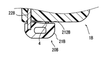
図13は、図12の状態におけるグリップ部の付近を示す図であり、
図14は、本開示の第4実施形態の電子キーのロック部の付近の拡大断面図であり、
図15は、メカニカルキーが差し込まれていき最初にロック状態となった状態を示す図である。
以下、本開示の実施形態を図面に基づいて説明する。図1は、第1実施形態の電子キー1の平面図である。この電子キー1は、車両のドアロックを解錠状態から施錠状態、あるいは、その反対に施錠状態から解錠状態に切り替えさせるための信号を、車両に備えられている受信機に送信する。なお、図1では、電子キー1のスイッチ部など一部の構造は省略している。
(第1実施形態)
図1に示すように、電子キー1の平面形状は、角が丸くなっている四角形状である。ケース10の平面形状は、一つの角部が欠けた形状であり、その欠けている部分に、メカニカルキー20のグリップ部21が位置する。よって、グリップ部21は、ケース10から露出している。
図1に示すように、電子キー1の平面形状は、角が丸くなっている四角形状である。ケース10の平面形状は、一つの角部が欠けた形状であり、その欠けている部分に、メカニカルキー20のグリップ部21が位置する。よって、グリップ部21は、ケース10から露出している。
グリップ部21に隣接してケース10から突き出しているのは、リリースフック31の突起部312である。電子キー1の厚さは、図1に示す縦方向長さ、および、横方向長さよりも短い。つまり、電子キー1は扁平な形状である。
[内部概略構成]
図2に電子キー1の内部構造を示す。ケース10は、樹脂製であり、相対的に短辺となる壁部である短壁部111、112と、これら短壁部111、112よりも長い長壁部113、114を備える。これら、短壁部111、112と長壁部113、114、および、底部120と底部120に対向する図示しない蓋部とにより形成される空間に、電子部品が収納される。なお、図2では電子部品は省略している。
図2に電子キー1の内部構造を示す。ケース10は、樹脂製であり、相対的に短辺となる壁部である短壁部111、112と、これら短壁部111、112よりも長い長壁部113、114を備える。これら、短壁部111、112と長壁部113、114、および、底部120と底部120に対向する図示しない蓋部とにより形成される空間に、電子部品が収納される。なお、図2では電子部品は省略している。
メカニカルキー20は、グリップ部21と棒状部22とを備える。グリップ部21は、ケース10と同じ樹脂で作られている。グリップ部21には、貫通穴211が形成されており、この貫通穴211に、キーホルダ用のリングなどが挿し通される。
棒状部22は、金属製であり、キー溝および鍵山の少なくとも一方が形成されている。棒状部22は基部がグリップ部21に差し込まれている。メカニカルキー20の棒状部22を、車両ドアのキーシリンダに差し込むことでも、車両のドアロックを解錠状態から施錠状態、あるいは、施錠状態から解錠状態に切り替えることができる。
ケース10の長壁部113には、メカニカルキー20の棒状部22を収容する収容穴130が形成されている。メカニカルキー20の棒状部22が収容穴130に収容された状態が、メカニカルキー20がケース10に収納された状態である。棒状部22が収容穴130に正常な位置まで収容された状態では、グリップ部21の、棒状部22が突き出している側の面である平面状のケース当接面212が、ケース10のグリップ対向面115に接触する。
メカニカルキー20がケース10に収納された状態では、メカニカルキー20がケース10から抜け落ちることを抑制する必要がある。そのため、ケース10には、ロック部30も収容されている。ロック部30は、ケース10の短壁部111に形成されたロック部収容空間116に収容されている。
[ロック部30の構成]
ロック部30の構成および、グリップ部21のうち、ロック部30に関連する構成を、図3を用いて説明する。グリップ部21には、ケース当接面212側の端に、ロック部30の方向に突き出す突起213が形成されている。この突起213のケース外側の面は、ロック部30と係合する係合平面214になっている。係合平面214はキー側係合平面に相当する。
ロック部30の構成および、グリップ部21のうち、ロック部30に関連する構成を、図3を用いて説明する。グリップ部21には、ケース当接面212側の端に、ロック部30の方向に突き出す突起213が形成されている。この突起213のケース外側の面は、ロック部30と係合する係合平面214になっている。係合平面214はキー側係合平面に相当する。
係合平面214は、メカニカルキー20の棒状部22の軸方向、換言すれば、メカニカルキー20の抜き差し方向に垂直な平面である。なお、以下の記載におけるキー抜き差し方向は、メカニカルキー20の抜き差し方向を意味する。
ロック部30は、リリースフック31と、バネ32と、ケース10に形成されているストッパ部33とを備えている。リリースフック31は、図3に示す位置では、メカニカルキー20のグリップ部21が、ケース10から離隔する方向に移動することを抑制する。メカニカルキー20のグリップ部21がケース10から離隔する方向に移動することを、リリースフック31が抑制している状態が、ロック状態である。このリリースフック31も樹脂製である。
抑制部材に相当するリリースフック31は、中央部311、突起部312、外側ガイド部313、先端部314を備える。中央部311はリリースフック31の中央の部分であり、バネ当接面3111を備える。バネ当接面3111には、バネ32の一方の端部が当接している。バネ32の他端は、ケース10に形成された、バネ当接面3111に対向する面である支持面119に支持されている。このバネ32により、リリースフック31は、グリップ部21に近づく方向に付勢される。バネ32は、圧縮コイルバネである。なお、図2~図4においては、バネ32は、簡略化して表している。
また、中央部311は、バネ当接面3111とは反対側に、ストッパ当接面3112を備える。リリースフック31がグリップ部21に近づく方向に移動すると、ストッパ当接面3112は、ストッパ部33に形成されたフック当接面331に接触する。ストッパ当接面3112とフック当接面331とが接触することで、リリースフック31が、それ以上、グリップ部21の方向に移動することが阻止される。
突起部312は、中央部311のバネ当接面3111の付近において中央部311と連結して、中央部311からケース外側方向に突き出している。突起部312は、ユーザにより操作可能なように、先端がケース10から突き出しており、突起部312をバネ32の付勢力に抗する方向に移動させると、ロック状態が解除され、メカニカルキー20をケース10から抜き出すことができる。
外側ガイド部313は、中央部311のバネ当接面3111から、ケース10の支持面119の方向に突き出している。この外側ガイド部313は、ケース10に形成された外側ガイド面117に接触しつつ移動する。また、中央部311の底面3113は、ケース10に形成された内側ガイド面118に接触する。この構成により、リリースフック31の移動方向は、外側ガイド面117および内側ガイド面118に沿った方向に制限される。その結果、リリースフック31の移動可能方向は、メカニカルキー20の抜き差し方向に対して垂直方向になる。
先端部314は、中央部311から、バネ当接面3111とは反対の方向となるグリップ部21の方向に突き出している。先端部314は、外側傾斜面3141、第1係合平面3142、第2係合平面3143、内側傾斜面3144を備える。
外側傾斜面3141は、グリップ部21に近くなるほど、キー抜き差し方向の位置が、ケース当接面212に近くなる傾斜となっている。
第1係合平面3142および第2係合平面3143は、キー抜き差し方向に垂直な平面である。第1係合平面3142は、第2係合平面3143よりも、リリースフック31の先端側に形成されている。換言すれば、第1係合平面3142は、第2係合平面3143よりも、グリップ部21においてリリースフック31側の側面であるフック対向側面215に近い位置に形成されている。
また、第1係合平面3142と第2係合平面3143とは、キー抜き差し方向の位置も異なる。第1係合平面3142は、第2係合平面3143よりも、キー抜き差し方向においてキー抜き取り方向(つまり、ケース10の外周側)に位置する。
これら、第1係合平面3142と第2係合平面3143は、いずれもロック側係合平面であり、第1係合平面3142と第2係合平面3143との間にキー抜き差し方向の段差があるので、本実施形態のロック側係合平面は段差平面構造になっている。
連結面に相当する内側傾斜面3144は、第1係合平面3142と第2係合平面3143とを連結している平面である。内側傾斜面3144は、外側傾斜面3141とは反対に、グリップ部21のフック対向側面215に近くなるほど、キー抜き差し方向の位置が、ケース当接面212から遠くなる傾斜となっている。
[キー差し込み時の作動]
次に、メカニカルキー20をケース10に差し込む際の作動を説明する。メカニカルキー20がケース10に差し込まれていくと、ケース当接面212が、リリースフック31の先端部314に形成された外側傾斜面3141に接触する。ケース当接面212が外側傾斜面3141に接触した状態で、メカニカルキー20がさらにキー差し込み方向に移動すると、ケース当接面212が外側傾斜面3141を押圧する。これにより、リリースフック31は、中央部311のストッパ当接面3112がストッパ部33のフック当接面331に接触した状態から、図4に示すように、バネ32を圧縮する方向に移動する。
次に、メカニカルキー20をケース10に差し込む際の作動を説明する。メカニカルキー20がケース10に差し込まれていくと、ケース当接面212が、リリースフック31の先端部314に形成された外側傾斜面3141に接触する。ケース当接面212が外側傾斜面3141に接触した状態で、メカニカルキー20がさらにキー差し込み方向に移動すると、ケース当接面212が外側傾斜面3141を押圧する。これにより、リリースフック31は、中央部311のストッパ当接面3112がストッパ部33のフック当接面331に接触した状態から、図4に示すように、バネ32を圧縮する方向に移動する。
さらに、グリップ部21がキー差し込み方向に移動すると、グリップ部21の係合平面214と、リリースフック31の先端部314に形成されている第1係合平面3142のキー抜き差し方向の位置が一致する。リリースフック31はバネ32によりグリップ部21の方向に付勢されているので、係合平面214と第1係合平面3142のキー抜き差し方向の位置が一致すると、リリースフック31はグリップ部21の方向に移動する。これにより、図5に示すように、係合平面214と第1係合平面3142が互いに接触する状態となるので、メカニカルキー20は、ケース10から抜け落ちることが抑制される。
図5に示す状態では、まだ、グリップ部21のケース当接面212とケース10のグリップ対向面115との間に隙間が存在する。したがって、図6に示すように、ケース当接面212とグリップ対向面115との間に、ゴミなどの異物4が存在していても、ロック状態とすることができる。
図5に示す状態から、さらにメカニカルキー20がキー差し込み方向に移動すると、係合平面214の端と内側傾斜面3144が接触しつつ、係合平面214の端が内側傾斜面3144に接触する位置が、第2係合平面3143の方向に移動する。
そして、ケース当接面212とグリップ対向面115とが接触する状態では、係合平面214と第2係合平面3143のキー抜き差し方向の位置が一致する。したがって、リリースフック31は図5の位置からさらにグリップ部21の方向に移動し、図3に示す状態となる。図3に示す状態では、リリースフック31の第2係合平面3143と、グリップ部21の係合平面214とが接触する。この図3に示す状態もロック状態であり、図3に示す状態では、図5に示す状態と異なり、グリップ部21の先端は、ケース10から突き出していないことから、図5の状態よりもデザイン性が向上する。
[第1実施形態のまとめ]
以上、説明した第1実施形態では、リリースフック31は、グリップ部21の係合平面214と係合できる第1係合平面3142、第2係合平面3143を備える。第1係合平面3142および第2係合平面3143は、キー抜き差し方向の位置が異なっており、かつ、これら第1係合平面3142と第2係合平面3143は、いずれも、グリップ部21の係合平面214と係合可能である。
以上、説明した第1実施形態では、リリースフック31は、グリップ部21の係合平面214と係合できる第1係合平面3142、第2係合平面3143を備える。第1係合平面3142および第2係合平面3143は、キー抜き差し方向の位置が異なっており、かつ、これら第1係合平面3142と第2係合平面3143は、いずれも、グリップ部21の係合平面214と係合可能である。
したがって、ゴミ等の異物4が存在して、メカニカルキー20が完全には収容穴130に差し込まれていないときでも、第2係合平面3143が係合平面214と係合すれば、メカニカルキー20の抜け落ちを抑制できる。
また、係合平面214、第1係合平面3142、第2係合平面3143は、キー抜き差し方向に垂直な平面である。よって、ロック状態でメカニカルキー20がキー抜き取り方向に引っ張られた場合に、リリースフック31がメカニカルキー20の棒状部22から離隔する方向に移動し、それにより、ケース10から抜ける方向にメカニカルキー20が移動してしまうことはない。よって、メカニカルキー20が引っ張られた際のがたつきも抑制できる。
また、本実施形態では、第1係合平面3142と第2係合平面3143との間は、内側傾斜面3144となっている。したがって、グリップ部21の係合平面214が、第1係合平面3142と係合している状態から第2係合平面3143と係合する状態まで、メカニカルキー20をケース10に差し込む際に必要な力が少なくて済む。
(第2実施形態)
次に、第2実施形態を説明する。この第2実施形態以下の説明において、それまでに使用した符号と同一番号の符号を有する要素は、特に言及する場合を除き、それ以前の実施形態における同一符号の要素と同一である。また、構成の一部のみを説明している場合、構成の他の部分については先に説明した実施形態を適用できる。
次に、第2実施形態を説明する。この第2実施形態以下の説明において、それまでに使用した符号と同一番号の符号を有する要素は、特に言及する場合を除き、それ以前の実施形態における同一符号の要素と同一である。また、構成の一部のみを説明している場合、構成の他の部分については先に説明した実施形態を適用できる。
第2実施形態の電子キー1Aは、図7に示す構成を備えている。この電子キー1Aは、メカニカルキー20Aのグリップ部21Aが備えている突起213Aの構成と、ロック部30Aが備えるリリースフック31Aの先端部314Aの構成が、それぞれ、第1実施形態の突起213、先端部314と相違する。これら第1実施形態と相違する構成を、図8を用いて説明する。
[第1実施形態と相違する構成の説明]
図8に示すように、グリップ部21Aが備えている突起213Aは、グリップ部21Aのケース当接面212側の端において、ロック部30Aの方向に突き出している。
図8に示すように、グリップ部21Aが備えている突起213Aは、グリップ部21Aのケース当接面212側の端において、ロック部30Aの方向に突き出している。
この突起213Aのケース外側の面には、ロック部30と係合する第1係合平面216と第2係合平面217が形成されている。第1係合平面216、第2係合平面217は、いずれも、キー抜き差し方向に垂直な平面である。
第1係合平面216は、第2係合平面217よりも、リリースフック31Aに近い側に形成されている。換言すれば、第1係合平面216は、第2係合平面217よりも、グリップ部21Aの外側、つまり、フック対向側面215から遠い位置に形成されている。
また、第1係合平面216と第2係合平面217とは、キー抜き差し方向の位置も異なる。第1係合平面216は、第2係合平面217よりも、キー抜き差し方向においてキー差し込み方向に位置する。
これら第1係合平面216と第2係合平面217は、いずれもキー側係合平面であり、第1係合平面216と第2係合平面217との間にキー抜き差し方向の段差があるので、第2実施形態ではキー側係合平面が段差平面構造になっている。
これら第1係合平面216、第2係合平面217との間は、連結面218により連結されている。連結面218は、フック対向側面215に近くなるほど、キー抜き差し方向の位置が、ケース当接面212から遠くなる傾斜を有する平面である。
第1実施形態のリリースフック31の先端部314は、グリップ部21の突起213に形成された係合平面214と係合する面として、第1係合平面3142、第2係合平面3143を備えていた。これに対して、リリースフック31Aの先端部314Aは、グリップ部21Aの突起213Aに形成された第1係合平面216、第2係合平面217と係合する面として、1つの係合平面3145を備える。第2実施形態では、係合平面3145がロック側係合平面に相当する。また、リリースフック31Aは抑制部材に相当する。
係合平面3145は、キー抜き差し方向の位置が第1実施形態の第2係合平面3143と同じである。また、係合平面3145の面積は、第1実施形態の第1係合平面3142の面積と、第2係合平面3143の面積と、内側傾斜面3144を第2係合平面3143を含む平面に投影した面積を合計した面積の和と同じになっている。
[キー差し込み時の作動]
次に、メカニカルキー20Aをケース10に差し込む際の作動を説明する。メカニカルキー20Aがケース10に差し込まれていき、第1係合平面216と係合平面3145のキー抜き差し方向の位置が一致すると、図8に示すように、それら第1係合平面216と係合平面3145が係合する。これにより、メカニカルキー20Aのグリップ部21Aがケース10から離隔する方向に移動することが抑制されているロック状態となる。
次に、メカニカルキー20Aをケース10に差し込む際の作動を説明する。メカニカルキー20Aがケース10に差し込まれていき、第1係合平面216と係合平面3145のキー抜き差し方向の位置が一致すると、図8に示すように、それら第1係合平面216と係合平面3145が係合する。これにより、メカニカルキー20Aのグリップ部21Aがケース10から離隔する方向に移動することが抑制されているロック状態となる。
この図8に示す状態では、グリップ部21Aのケース当接面212とケース10のグリップ対向面115との間に隙間が存在する。したがって、ケース当接面212とグリップ対向面115との間に、ゴミなどの異物が存在していても、ロック状態とすることができる。
図8に示す状態から、さらにメカニカルキー20Aがキー差し込み方向に移動すると、係合平面3145の端と連結面218が接触しつつ、係合平面3145の端が連結面218に接触する位置が、第2係合平面217の方向に移動する。
ケース当接面212とグリップ対向面115とが接触する状態になると、第2係合平面217と係合平面3145のキー抜き差し方向の位置が一致する。したがって、リリースフック31Aは図8の位置からさらにグリップ部21Aの方向に移動し、図9に示す状態となる。図9に示す状態では、第2係合平面217と係合平面3145とが接触する。この図9に示す状態もロック状態であり、図9に示す状態では、グリップ部21Aの先端がケース10から突き出していないことから、図8の状態よりもデザイン性が向上する。
(第3実施形態)
第3実施形態の電子キー1Bの構成を図10に示す。図10は、第1実施形態における図2に対応する図である。ケース10Bは、短壁部111B、112Bと、短壁部111B、112Bよりも長い長壁部113B、114Bを備える。これら、短壁部111B、112Bと長壁部113B、114B、および、底部120と底部120に対向する図示しない蓋部とにより形成される空間に、電子部品が収納される。なお、図10でも電子部品は省略している。
第3実施形態の電子キー1Bの構成を図10に示す。図10は、第1実施形態における図2に対応する図である。ケース10Bは、短壁部111B、112Bと、短壁部111B、112Bよりも長い長壁部113B、114Bを備える。これら、短壁部111B、112Bと長壁部113B、114B、および、底部120と底部120に対向する図示しない蓋部とにより形成される空間に、電子部品が収納される。なお、図10でも電子部品は省略している。
メカニカルキー20Bは、グリップ部21Bと棒状部22Bとを備える。グリップ部21Bは樹脂製であり、棒状部22Bは金属製である。棒状部22Bは、基部がグリップ部21Bに差し込まれている。
ケース10Bの短壁部112Bから長壁部113Bにかけて、メカニカルキー20Bの棒状部22Bを収容する収容穴130Bが形成されている。収容穴130Bは、短壁部112Bの端面に開口を有する。
メカニカルキー20Bの棒状部22Bが収容穴130Bに収容された状態が、メカニカルキー20Bがケース10Bに収納された状態である。第2実施形態では、メカニカルキー20Bがケース10Bに収容された状態でも、グリップ部21Bは、ケース10Bから突き出している。棒状部22が収容穴130Bに正常な位置まで収容された状態では、グリップ部21の、棒状部22が突き出している側の面であるケース当接面212Bが、短壁部112Bと接触する。
ケース10Bの長壁部113Bには、収容穴130Bに連結してロック部収容空間116Bが形成されている。このロック部収容空間116Bにロック部30Bが収容されている。ロック部30Bは、抑制部材に相当するリリースフック31Bと、バネ32Bを備えている。
[ロック部30Bの構成]
次にロック部30Bの構成を図11を用いて説明する。第3実施形態のリリースフック31Bは揺動型であり、リリースフック31Bの中心付近に位置し、揺動軸として機能する軸35を揺動中心として揺動可能になっている。バネ32Bはねじりコイルバネであり、一方の端部がロック部収容空間116Bの底に接しており、他方の端部がリリースフック31Bの裏面311Bに形成された収容部312Bに収容されている。バネ32Bの図示しないコイル部は軸35に巻きつけられている。
次にロック部30Bの構成を図11を用いて説明する。第3実施形態のリリースフック31Bは揺動型であり、リリースフック31Bの中心付近に位置し、揺動軸として機能する軸35を揺動中心として揺動可能になっている。バネ32Bはねじりコイルバネであり、一方の端部がロック部収容空間116Bの底に接しており、他方の端部がリリースフック31Bの裏面311Bに形成された収容部312Bに収容されている。バネ32Bの図示しないコイル部は軸35に巻きつけられている。
収容部312Bは、リリースフック31Bにおいて、キー抜き差し方向のグリップ部21Bとは反対側の端に位置している。この収容部312Bにバネ32Bの端が収容され、バネ32Bのコイル部が軸35に巻きつけられているので、リリースフック31Bの収容部312Bがロック部収容空間116Bの底面から離隔する方向に、リリースフック31Bは付勢されている。
リリースフック31Bの、収容部312Bとは反対側の端部には、凸部313Bが形成されている。凸部313Bは、リリースフック31Bの基部314Bから、ロック部収容空間116Bの底面方向に突き出している。
凸部313Bは、傾斜面315Bと、第1係合平面316Bと、第2係合平面317Bと、連結面318Bとを備えている。傾斜面315Bは、リリースフック31Bの揺動角度によらず、キー抜き差し方向に対して傾斜している面であり、傾斜方向は、キー抜き差し方向がキー差し込み方向であるほど、ロック部収容空間116Bの底面に向かう方向である。なお、傾斜とは、水平でも垂直でもない角度である。
第1係合平面316Bと第2係合平面317Bは、いずれも、メカニカルキー20Bの棒状部22Bの先端に形成された係合平面221Bと係合する平面である。これら第1係合平面316Bおよび第2係合平面317Bは、リリースフック31Bの回転角度により、メカニカルキー20Bの棒状部22Bの軸方向に対する角度が変化する。しかし、第1係合平面316Bおよび第2係合平面317Bともに、係合平面221Bと係合している位置において、キー抜き差し方向に垂直になる。
第1係合平面316Bは、第2係合平面317Bよりも、リリースフック31Bの基部314Bに近い位置に形成されている。また、第1係合平面316Bと第2係合平面317Bとは、キー抜き差し方向の位置も異なる。第1係合平面316Bは、第2係合平面317Bよりも、キー抜き差し方向においてキー抜き取り方向、すなわち、収容穴130Bの、短壁部112Bの端面側の開口に近い位置に形成されている。
第1係合平面316Bと第2係合平面317Bは、いずれもフック部側係合平面であり、第1係合平面316Bと第2係合平面317Bの間にキー抜き差し方向の段差があるので、第3実施形態ではフック部側係合平面が段差平面構造になっている。
連結面318Bは、第1係合平面316Bと第2係合平面317Bとを連結する。メカニカルキー20Bの棒状部22Bの先端には、棒状部22Bを軸に直交する方向に貫通する貫通穴222Bが形成されており、貫通穴222Bの側面の一部が係合平面221Bとなっている。係合平面221Bはキー側係合平面に相当しており、キー抜き差し方向、すなわち、棒状部22Bの軸方向に垂直であり、棒状部22Bの厚さ方向の全体に渡り形成されている。
[キー差し込み時の作動]
次に、メカニカルキー20Bをケース10Bに差し込む際の作動を説明する。メカニカルキー20Bがケース10Bに差し込まれていくと、メカニカルキー20Bの棒状部22Bの先端が、リリースフック31Bの傾斜面315Bに接触する。さらにメカニカルキー20Bがケース10Bに差し込まれると、リリースフック31Bの傾斜面315Bがメカニカルキー20Bの棒状部22Bの先端に押圧される。これにより、リリースフック31Bは、軸35を揺動中心として、凸部313Bの先端がロック部収容空間116Bの底面から離隔する方向に回転移動する。
次に、メカニカルキー20Bをケース10Bに差し込む際の作動を説明する。メカニカルキー20Bがケース10Bに差し込まれていくと、メカニカルキー20Bの棒状部22Bの先端が、リリースフック31Bの傾斜面315Bに接触する。さらにメカニカルキー20Bがケース10Bに差し込まれると、リリースフック31Bの傾斜面315Bがメカニカルキー20Bの棒状部22Bの先端に押圧される。これにより、リリースフック31Bは、軸35を揺動中心として、凸部313Bの先端がロック部収容空間116Bの底面から離隔する方向に回転移動する。
この回転移動により、メカニカルキー20Bの棒状部22Bの先端は凸部313Bの先端を通過できる。メカニカルキー20Bがさらにケース10Bに差し込まれると、棒状部22Bの先端部に形成されている係合平面221Bと、リリースフック31Bに形成された第1係合平面316Bのキー抜き差し方向の位置が一致する。これにより、図12に示すように、それら係合平面221Bと第1係合平面316Bが係合するので、メカニカルキー20Bのグリップ部21Bがケース10Bから離隔する方向に移動することが抑制されているロック状態となる。
この図12に示す状態におけるグリップ部21Bの付近を図13に示す。係合平面221Bと第1係合平面316Bが係合している状態では、図13に示すように、グリップ部21Bのケース当接面212Bと短壁部112Bとの間に隙間が存在する。したがって、ケース当接面212と短壁部112Bとの間に、ゴミなどの異物4が存在していても、ロック状態とすることができる。
図12に示す状態から、さらにメカニカルキー20Bがキー差し込み方向に移動すると、第2係合平面317Bと係合平面221Bのキー抜き差し方向の位置が一致する。したがって、リリースフック31Bは図12の回転位置から凸部313Bがロック部収容空間116の底面に近づく方向に回転移動し、図11に示す状態となる。
図11に示す状態では、第2係合平面317Bと係合平面221Bとが接触する。この図11に示す状態もロック状態であり、図11に示す状態では、リリースフック31Bの表面319Bが、ケース10Bの長壁部113Bから突き出していないことから、図12の状態よりもデザイン性が向上する。
(第4実施形態)
第4実施形態の電子キー1Cの構成を図14に示す。図14は図11に対応する図であり、図14に示していない部分の構成は、第3実施形態の電子キー1Bと同じである。
第4実施形態の電子キー1Cの構成を図14に示す。図14は図11に対応する図であり、図14に示していない部分の構成は、第3実施形態の電子キー1Bと同じである。
電子キー1Cは、メカニカルキー20Cの棒状部22Cの先端部の構成と、ロック部30Cが備えるリリースフック31Cの凸部313Cの構成が、それぞれ、第3実施形態の棒状部22B、凸部313Bと相違する。なお、リリースフック31Cは抑制部材に相当する。
メカニカルキー20Cの棒状部22Cには、貫通穴222Cが、第3実施形態の貫通穴222Bと同じ位置に形成されている。第3実施形態では、貫通穴222Bに一つの係合平面221Bが形成されていた。これに対して、第4実施形態では、係合平面221Bに代えて、第1係合平面223C、第2係合平面224C、連結面225Cが形成されている。第1係合平面223Cと第2係合平面224Cは、いずれも、凸部313Cに形成された係合平面317Cと係合する平面である。これら第1係合平面223Cおよび第2係合平面224Cは、いずれも、キー抜き差し方向に垂直な平面、すなわち、棒状部22Cの軸方向に垂直な平面である。
第1係合平面223Cは、第2係合平面224Cよりも、メカニカルキー20Cがケース10Bに差し込まれた状態でリリースフック31Cの基部314Bに近い位置に形成されている。また、第1係合平面223Cと第2係合平面224Cとは、キー抜き差し方向の位置も異なる。第1係合平面223Cは、第2係合平面224Cよりも、キー抜き差し方向においてキー差し込み方向、すなわち、メカニカルキー20Cの棒状部22Cの先端に近い位置に形成されている。
第1係合平面223Cと第2係合平面224Cは、いずれもキー側係合平面であり、第1係合平面223Cと第2係合平面224Cの間にキー抜き差し方向の段差があるので、第4実施形態ではキー側係合平面が段差平面構造になっている。
連結面225Cは、第1係合平面316Bと第2係合平面317Bとを連結する平面であり、棒状部22Cの先端に近くなるほど、リリースフック31Cの基部314Bに近くなる傾斜を有する平面である。
リリースフック31Cの凸部313Cには、係合平面317Cが形成されている。この係合平面317Cは、第3実施形態の凸部313Bに形成されていた第1係合平面316B、第2係合平面317B、連結面318に代えて設けられている。係合平面317Cはロック側係合平面に相当する。
[キー差し込み時の作動]
次に、メカニカルキー20Cをケース10Bに差し込む際の作動を説明する。メカニカルキー20Cがケース10Bに差し込まれていくと、メカニカルキー20Cの棒状部22Cの先端に形成されている第1係合平面223Cと、リリースフック31Cの凸部313Cに形成された係合平面317Cのキー抜き差し方向の位置が一致する。これにより、図15に示すように、それら係合平面317Cと第1係合平面223Cが係合するので、メカニカルキー20Cのグリップ部がケース10Bから離隔する方向に移動することが抑制されているロック状態となる。
次に、メカニカルキー20Cをケース10Bに差し込む際の作動を説明する。メカニカルキー20Cがケース10Bに差し込まれていくと、メカニカルキー20Cの棒状部22Cの先端に形成されている第1係合平面223Cと、リリースフック31Cの凸部313Cに形成された係合平面317Cのキー抜き差し方向の位置が一致する。これにより、図15に示すように、それら係合平面317Cと第1係合平面223Cが係合するので、メカニカルキー20Cのグリップ部がケース10Bから離隔する方向に移動することが抑制されているロック状態となる。
この図15に示す状態では、第3実施形態と同様、メカニカルキー20Cのグリップ部とケース10Bとの間に隙間が存在する。したがって、その隙間にゴミなどの異物が存在していても、ロック状態とすることができる。
図15に示す状態から、さらにメカニカルキー20Cがキー差し込み方向に移動すると、第2係合平面224Cと係合平面317Cのキー抜き差し方向の位置が一致する。したがって、リリースフック31Cは図15の回転位置から凸部313Cがロック部収容空間116の底面に近づく方向に回転移動し、図14に示す状態となる。
図14に示す状態では、第2係合平面224Cと係合平面317Cとが接触する。この図14に示す状態もロック状態である。
(変形例1)
これまで説明した第1~第4実施形態では、キー側係合平面とロック側係合平面の一方は、一つの平面のみの構成であった。しかし、キー側係合平面とロック側係合平面が、両方とも、複数の係合平面を備えていてもよい。
これまで説明した第1~第4実施形態では、キー側係合平面とロック側係合平面の一方は、一つの平面のみの構成であった。しかし、キー側係合平面とロック側係合平面が、両方とも、複数の係合平面を備えていてもよい。
(変形例2)
これまで説明した第1~第4実施形態において、段差平面構造となっている側の係合平面は、2つの係合平面を備えていたが、3つ以上の係合平面を備えていてもよい。
これまで説明した第1~第4実施形態において、段差平面構造となっている側の係合平面は、2つの係合平面を備えていたが、3つ以上の係合平面を備えていてもよい。
本開示は、実施例に準拠して記述されたが、本開示は当該実施例や構造に限定されるものではないと理解される。本開示は、様々な変形例や均等範囲内の変形をも包含する。加えて、様々な組み合わせや形態、さらには、それらに一要素のみ、それ以上、あるいはそれ以下、を含む他の組み合わせや形態をも、本開示の範畴や思想範囲に入るものである。
Claims (9)
- 棒状部を有するメカニカルキー(20、20A、20B、20C)と、
前記メカニカルキーを、前記棒状部の軸方向に抜き差し可能に収納するケース(10、10B)と、
前記ケースに設けられ、前記メカニカルキーが前記ケースから抜け落ちることを抑制するための抑制部材(31、31A、31B、31C)とを備えた電子キーであって、
前記メカニカルキーは、前記抑制部材により前記ケースから抜け落ちることが抑制されているロック状態において前記棒状部の軸方向に垂直な平面であるキー側係合平面(214、216、217、221B、223C、224C)を備え、
前記抑制部材は、前記ロック状態において前記棒状部の軸方向に垂直な平面であって、前記キー側係合平面と係合するロック側係合平面(3142、3143、3145、316B、317B、317C)を備え、
前記キー側係合平面および前記ロック側係合平面の少なくとも一方は、前記メカニカルキーの前記棒状部の軸方向における位置が異なり、かつ、前記キー側係合平面および前記ロック側係合平面のうちの他方と係合可能な複数の係合平面を備える段差平面構造になっている電子キー。 - 請求項1において、
前記抑制部材(31、31A)は、前記ケースに収容された状態の前記メカニカルキーの前記棒状部の軸方向に対して垂直方向に移動可能である電子キー。 - 請求項1において、
前記抑制部材(31B、31C)は、揺動軸周りに揺動可能であり、
前記ロック側係合平面(316B、317B、317C)は、前記抑制部材の揺動角度により前記メカニカルキーの前記棒状部の軸方向に対する角度が変化し、前記ロック状態において前記棒状部の軸方向に垂直になる電子キー。 - 請求項1~3のいずれか1項において、
前記段差平面構造になっている複数の係合平面であって、互いに隣り合う2つの前記係合平面の間を連結する連結面(3144、218、225C)が、前記棒状部の軸方向に対して傾斜している電子キー。 - 請求項1~4のいずれか1項において、
前記キー側係合平面および前記ロック側係合平面の一方は、前記段差平面構造になっている一方で、前記キー側係合平面および前記ロック側係合平面の他方は、前記キー側係合平面および前記ロック側係合平面の一方と係合する平面が一つである電子キー。 - 請求項5において、
前記メカニカルキー(20)は、前記棒状部と連結し、かつ、前記ケースから少なくとも一部がユーザにより把持可能に露出するグリップ部(21)を備え、
前記グリップ部に前記キー側係合平面が備えられ、
前記ロック側係合平面が前記段差平面構造になっている電子キー。 - 請求項5において、
前記メカニカルキー(20A)は、前記棒状部と連結し、かつ、前記ケースから少なくとも一部がユーザにより把持可能に露出するグリップ部(21A)を備え、
前記グリップ部に前記キー側係合平面が備えられ、
前記キー側係合平面が前記段差平面構造になっている電子キー。 - 請求項5において、
前記メカニカルキー(20B)は、前記棒状部の先端部に前記キー側係合平面を備え、
前記ロック側係合平面が前記段差平面構造になっている電子キー。 - 請求項5において、
前記メカニカルキー(20C)は、前記棒状部の先端部に前記キー側係合平面を備え、
前記キー側係合平面が前記段差平面構造になっている電子キー。
Priority Applications (2)
| Application Number | Priority Date | Filing Date | Title |
|---|---|---|---|
| US16/305,108 US11149468B2 (en) | 2016-05-31 | 2017-04-12 | Electronic key |
| CN201780033028.7A CN109196176B (zh) | 2016-05-31 | 2017-04-12 | 电子钥匙 |
Applications Claiming Priority (2)
| Application Number | Priority Date | Filing Date | Title |
|---|---|---|---|
| JP2016108713A JP6536487B2 (ja) | 2016-05-31 | 2016-05-31 | 電子キー |
| JP2016-108713 | 2016-05-31 |
Publications (1)
| Publication Number | Publication Date |
|---|---|
| WO2017208634A1 true WO2017208634A1 (ja) | 2017-12-07 |
Family
ID=60479263
Family Applications (1)
| Application Number | Title | Priority Date | Filing Date |
|---|---|---|---|
| PCT/JP2017/014905 Ceased WO2017208634A1 (ja) | 2016-05-31 | 2017-04-12 | 電子キー |
Country Status (4)
| Country | Link |
|---|---|
| US (1) | US11149468B2 (ja) |
| JP (1) | JP6536487B2 (ja) |
| CN (1) | CN109196176B (ja) |
| WO (1) | WO2017208634A1 (ja) |
Families Citing this family (4)
| Publication number | Priority date | Publication date | Assignee | Title |
|---|---|---|---|---|
| JP6501234B1 (ja) * | 2017-11-07 | 2019-04-17 | 三菱電機株式会社 | 電子キーシステムの携帯機 |
| KR102772332B1 (ko) * | 2019-09-25 | 2025-02-25 | 현대자동차주식회사 | 차량용 키 어셈블리 |
| JP2021123966A (ja) * | 2020-02-06 | 2021-08-30 | 株式会社リュウテック | 自動車用スマートキー |
| US12421761B2 (en) * | 2022-06-23 | 2025-09-23 | Db Imports Inc. | Folding lock pick set |
Citations (3)
| Publication number | Priority date | Publication date | Assignee | Title |
|---|---|---|---|---|
| JP2007277928A (ja) * | 2006-04-06 | 2007-10-25 | Tokai Rika Co Ltd | キー装置 |
| JP2009221767A (ja) * | 2008-03-18 | 2009-10-01 | Omron Corp | キーレスエントリシステム携帯機 |
| JP2014111857A (ja) * | 2011-03-31 | 2014-06-19 | Panasonic Corp | 電子キー |
Family Cites Families (18)
| Publication number | Priority date | Publication date | Assignee | Title |
|---|---|---|---|---|
| JP3751471B2 (ja) * | 1999-05-11 | 2006-03-01 | 株式会社東海理化電機製作所 | 電子部品内蔵キー装置 |
| JP3545647B2 (ja) * | 1999-06-11 | 2004-07-21 | 株式会社アルファ | 電子キイ構造 |
| JP4087655B2 (ja) * | 2002-07-23 | 2008-05-21 | 株式会社東海理化電機製作所 | メカキーを収容した携帯機 |
| JP4047715B2 (ja) * | 2002-12-11 | 2008-02-13 | 株式会社東海理化電機製作所 | セキュリティシステム及びセキュリティシステム用携帯機 |
| JP2004353404A (ja) * | 2003-05-30 | 2004-12-16 | Denso Corp | 電子キーシステムの携帯機 |
| JP4643152B2 (ja) * | 2004-01-30 | 2011-03-02 | 株式会社デンソー | 電子キーシステムの携帯機 |
| JP4777204B2 (ja) | 2006-09-27 | 2011-09-21 | 株式会社アルファ | キー装置 |
| US20100199729A1 (en) * | 2006-11-27 | 2010-08-12 | Michael Joseph Zaitz | Key fob assembly |
| US7634932B2 (en) * | 2006-12-01 | 2009-12-22 | Chrysler Group Llc | Fob integrated key |
| JP4953244B2 (ja) * | 2007-03-21 | 2012-06-13 | オムロンオートモーティブエレクトロニクス株式会社 | 携帯機 |
| JP5163776B2 (ja) * | 2010-07-13 | 2013-03-13 | 株式会社デンソー | カードキー |
| JP5168602B2 (ja) * | 2010-08-02 | 2013-03-21 | 株式会社デンソー | 携帯型無線キー |
| JP5557829B2 (ja) | 2011-12-07 | 2014-07-23 | オムロンオートモーティブエレクトロニクス株式会社 | 車両用携帯機 |
| CN102535964A (zh) * | 2011-12-30 | 2012-07-04 | 伟速达(福州)安全系统有限公司 | 车用智能钥匙结构 |
| CN202831836U (zh) * | 2011-12-30 | 2013-03-27 | 伟速达(福州)安全系统有限公司 | 车用智能钥匙的备用机械钥匙紧固装置 |
| CN203008545U (zh) * | 2012-10-19 | 2013-06-19 | 北京经纬恒润科技有限公司 | 一种汽车钥匙 |
| JP2016188511A (ja) * | 2015-03-30 | 2016-11-04 | 株式会社デンソー | 車両用電子キー |
| KR102009952B1 (ko) * | 2018-12-18 | 2019-08-12 | 콘티넨탈 오토모티브 시스템 주식회사 | 차량용 카드키 |
-
2016
- 2016-05-31 JP JP2016108713A patent/JP6536487B2/ja active Active
-
2017
- 2017-04-12 WO PCT/JP2017/014905 patent/WO2017208634A1/ja not_active Ceased
- 2017-04-12 US US16/305,108 patent/US11149468B2/en active Active
- 2017-04-12 CN CN201780033028.7A patent/CN109196176B/zh active Active
Patent Citations (3)
| Publication number | Priority date | Publication date | Assignee | Title |
|---|---|---|---|---|
| JP2007277928A (ja) * | 2006-04-06 | 2007-10-25 | Tokai Rika Co Ltd | キー装置 |
| JP2009221767A (ja) * | 2008-03-18 | 2009-10-01 | Omron Corp | キーレスエントリシステム携帯機 |
| JP2014111857A (ja) * | 2011-03-31 | 2014-06-19 | Panasonic Corp | 電子キー |
Also Published As
| Publication number | Publication date |
|---|---|
| US20200318387A1 (en) | 2020-10-08 |
| US11149468B2 (en) | 2021-10-19 |
| CN109196176A (zh) | 2019-01-11 |
| JP2017214754A (ja) | 2017-12-07 |
| CN109196176B (zh) | 2020-08-04 |
| JP6536487B2 (ja) | 2019-07-03 |
Similar Documents
| Publication | Publication Date | Title |
|---|---|---|
| WO2017208634A1 (ja) | 電子キー | |
| EP1355260B1 (en) | Card connector apparatus with locking mechanism for locking a card to mounting position | |
| US8353549B2 (en) | Push button mechanism for opening and closing a storage compartment for a vehicle | |
| US8973956B2 (en) | Latch device | |
| CN101918664A (zh) | 安全装置及开闭机构 | |
| EP3396090B1 (en) | Vehicle door handle device | |
| US20180029452A1 (en) | Vehicle opening and closing body operating device | |
| JP2002216728A (ja) | 電子機器筐体 | |
| WO2012132461A1 (ja) | 電子キー | |
| US12200883B2 (en) | Device for accommodating a component | |
| JP4620611B2 (ja) | 電子キー装置 | |
| JP6644041B2 (ja) | 扉の開閉識別装置 | |
| JP4857234B2 (ja) | ステアリングロック装置 | |
| US20080156628A1 (en) | Switch apparatus | |
| JP4763481B2 (ja) | 解錠キー装置 | |
| KR20210015797A (ko) | 액추에이터 유닛 및 안전 스위치 | |
| JP2010262819A (ja) | 押ボタンスイッチ | |
| JP5268547B2 (ja) | 電気機器収納用箱 | |
| JP2000120312A (ja) | イグニッションキー装置 | |
| JP6501234B1 (ja) | 電子キーシステムの携帯機 | |
| JP2576437Y2 (ja) | キャビネットにおける抽斗の安全係止装置 | |
| JP5929649B2 (ja) | 車載装置 | |
| JP2011213248A (ja) | ステアリングロック装置 | |
| JP2020014731A (ja) | 宅配ボックス | |
| WO2018182024A1 (ja) | ステアリングロック装置 |
Legal Events
| Date | Code | Title | Description |
|---|---|---|---|
| 121 | Ep: the epo has been informed by wipo that ep was designated in this application |
Ref document number: 17806194 Country of ref document: EP Kind code of ref document: A1 |
|
| NENP | Non-entry into the national phase |
Ref country code: DE |
|
| 122 | Ep: pct application non-entry in european phase |
Ref document number: 17806194 Country of ref document: EP Kind code of ref document: A1 |