WO2017208586A1 - 画像表示システム - Google Patents
画像表示システム Download PDFInfo
- Publication number
- WO2017208586A1 WO2017208586A1 PCT/JP2017/011924 JP2017011924W WO2017208586A1 WO 2017208586 A1 WO2017208586 A1 WO 2017208586A1 JP 2017011924 W JP2017011924 W JP 2017011924W WO 2017208586 A1 WO2017208586 A1 WO 2017208586A1
- Authority
- WO
- WIPO (PCT)
- Prior art keywords
- unit
- imaging
- vehicle
- image
- imaging range
- Prior art date
- Legal status (The legal status is an assumption and is not a legal conclusion. Google has not performed a legal analysis and makes no representation as to the accuracy of the status listed.)
- Ceased
Links
Images

Classifications
-
- B—PERFORMING OPERATIONS; TRANSPORTING
- B60—VEHICLES IN GENERAL
- B60R—VEHICLES, VEHICLE FITTINGS, OR VEHICLE PARTS, NOT OTHERWISE PROVIDED FOR
- B60R1/00—Optical viewing arrangements; Real-time viewing arrangements for drivers or passengers using optical image capturing systems, e.g. cameras or video systems specially adapted for use in or on vehicles
- B60R1/20—Real-time viewing arrangements for drivers or passengers using optical image capturing systems, e.g. cameras or video systems specially adapted for use in or on vehicles
- B60R1/22—Real-time viewing arrangements for drivers or passengers using optical image capturing systems, e.g. cameras or video systems specially adapted for use in or on vehicles for viewing an area outside the vehicle, e.g. the exterior of the vehicle
- B60R1/28—Real-time viewing arrangements for drivers or passengers using optical image capturing systems, e.g. cameras or video systems specially adapted for use in or on vehicles for viewing an area outside the vehicle, e.g. the exterior of the vehicle with an adjustable field of view
-
- B—PERFORMING OPERATIONS; TRANSPORTING
- B60—VEHICLES IN GENERAL
- B60K—ARRANGEMENT OR MOUNTING OF PROPULSION UNITS OR OF TRANSMISSIONS IN VEHICLES; ARRANGEMENT OR MOUNTING OF PLURAL DIVERSE PRIME-MOVERS IN VEHICLES; AUXILIARY DRIVES FOR VEHICLES; INSTRUMENTATION OR DASHBOARDS FOR VEHICLES; ARRANGEMENTS IN CONNECTION WITH COOLING, AIR INTAKE, GAS EXHAUST OR FUEL SUPPLY OF PROPULSION UNITS IN VEHICLES
- B60K35/00—Instruments specially adapted for vehicles; Arrangement of instruments in or on vehicles
- B60K35/10—Input arrangements, i.e. from user to vehicle, associated with vehicle functions or specially adapted therefor
-
- B—PERFORMING OPERATIONS; TRANSPORTING
- B60—VEHICLES IN GENERAL
- B60K—ARRANGEMENT OR MOUNTING OF PROPULSION UNITS OR OF TRANSMISSIONS IN VEHICLES; ARRANGEMENT OR MOUNTING OF PLURAL DIVERSE PRIME-MOVERS IN VEHICLES; AUXILIARY DRIVES FOR VEHICLES; INSTRUMENTATION OR DASHBOARDS FOR VEHICLES; ARRANGEMENTS IN CONNECTION WITH COOLING, AIR INTAKE, GAS EXHAUST OR FUEL SUPPLY OF PROPULSION UNITS IN VEHICLES
- B60K35/00—Instruments specially adapted for vehicles; Arrangement of instruments in or on vehicles
- B60K35/20—Output arrangements, i.e. from vehicle to user, associated with vehicle functions or specially adapted therefor
- B60K35/21—Output arrangements, i.e. from vehicle to user, associated with vehicle functions or specially adapted therefor using visual output, e.g. blinking lights or matrix displays
- B60K35/22—Display screens
-
- B—PERFORMING OPERATIONS; TRANSPORTING
- B60—VEHICLES IN GENERAL
- B60K—ARRANGEMENT OR MOUNTING OF PROPULSION UNITS OR OF TRANSMISSIONS IN VEHICLES; ARRANGEMENT OR MOUNTING OF PLURAL DIVERSE PRIME-MOVERS IN VEHICLES; AUXILIARY DRIVES FOR VEHICLES; INSTRUMENTATION OR DASHBOARDS FOR VEHICLES; ARRANGEMENTS IN CONNECTION WITH COOLING, AIR INTAKE, GAS EXHAUST OR FUEL SUPPLY OF PROPULSION UNITS IN VEHICLES
- B60K35/00—Instruments specially adapted for vehicles; Arrangement of instruments in or on vehicles
- B60K35/50—Instruments characterised by their means of attachment to or integration in the vehicle
-
- B—PERFORMING OPERATIONS; TRANSPORTING
- B60—VEHICLES IN GENERAL
- B60K—ARRANGEMENT OR MOUNTING OF PROPULSION UNITS OR OF TRANSMISSIONS IN VEHICLES; ARRANGEMENT OR MOUNTING OF PLURAL DIVERSE PRIME-MOVERS IN VEHICLES; AUXILIARY DRIVES FOR VEHICLES; INSTRUMENTATION OR DASHBOARDS FOR VEHICLES; ARRANGEMENTS IN CONNECTION WITH COOLING, AIR INTAKE, GAS EXHAUST OR FUEL SUPPLY OF PROPULSION UNITS IN VEHICLES
- B60K35/00—Instruments specially adapted for vehicles; Arrangement of instruments in or on vehicles
- B60K35/80—Arrangements for controlling instruments
- B60K35/81—Arrangements for controlling instruments for controlling displays
-
- B—PERFORMING OPERATIONS; TRANSPORTING
- B60—VEHICLES IN GENERAL
- B60K—ARRANGEMENT OR MOUNTING OF PROPULSION UNITS OR OF TRANSMISSIONS IN VEHICLES; ARRANGEMENT OR MOUNTING OF PLURAL DIVERSE PRIME-MOVERS IN VEHICLES; AUXILIARY DRIVES FOR VEHICLES; INSTRUMENTATION OR DASHBOARDS FOR VEHICLES; ARRANGEMENTS IN CONNECTION WITH COOLING, AIR INTAKE, GAS EXHAUST OR FUEL SUPPLY OF PROPULSION UNITS IN VEHICLES
- B60K35/00—Instruments specially adapted for vehicles; Arrangement of instruments in or on vehicles
- B60K35/90—Calibration of instruments, e.g. setting initial or reference parameters; Testing of instruments, e.g. detecting malfunction
-
- B—PERFORMING OPERATIONS; TRANSPORTING
- B60—VEHICLES IN GENERAL
- B60R—VEHICLES, VEHICLE FITTINGS, OR VEHICLE PARTS, NOT OTHERWISE PROVIDED FOR
- B60R1/00—Optical viewing arrangements; Real-time viewing arrangements for drivers or passengers using optical image capturing systems, e.g. cameras or video systems specially adapted for use in or on vehicles
- B60R1/20—Real-time viewing arrangements for drivers or passengers using optical image capturing systems, e.g. cameras or video systems specially adapted for use in or on vehicles
- B60R1/22—Real-time viewing arrangements for drivers or passengers using optical image capturing systems, e.g. cameras or video systems specially adapted for use in or on vehicles for viewing an area outside the vehicle, e.g. the exterior of the vehicle
- B60R1/23—Real-time viewing arrangements for drivers or passengers using optical image capturing systems, e.g. cameras or video systems specially adapted for use in or on vehicles for viewing an area outside the vehicle, e.g. the exterior of the vehicle with a predetermined field of view
- B60R1/26—Real-time viewing arrangements for drivers or passengers using optical image capturing systems, e.g. cameras or video systems specially adapted for use in or on vehicles for viewing an area outside the vehicle, e.g. the exterior of the vehicle with a predetermined field of view to the rear of the vehicle
-
- G—PHYSICS
- G03—PHOTOGRAPHY; CINEMATOGRAPHY; ANALOGOUS TECHNIQUES USING WAVES OTHER THAN OPTICAL WAVES; ELECTROGRAPHY; HOLOGRAPHY
- G03B—APPARATUS OR ARRANGEMENTS FOR TAKING PHOTOGRAPHS OR FOR PROJECTING OR VIEWING THEM; APPARATUS OR ARRANGEMENTS EMPLOYING ANALOGOUS TECHNIQUES USING WAVES OTHER THAN OPTICAL WAVES; ACCESSORIES THEREFOR
- G03B15/00—Special procedures for taking photographs; Apparatus therefor
-
- H—ELECTRICITY
- H04—ELECTRIC COMMUNICATION TECHNIQUE
- H04N—PICTORIAL COMMUNICATION, e.g. TELEVISION
- H04N7/00—Television systems
- H04N7/18—Closed-circuit television [CCTV] systems, i.e. systems in which the video signal is not broadcast
-
- H—ELECTRICITY
- H04—ELECTRIC COMMUNICATION TECHNIQUE
- H04N—PICTORIAL COMMUNICATION, e.g. TELEVISION
- H04N7/00—Television systems
- H04N7/18—Closed-circuit television [CCTV] systems, i.e. systems in which the video signal is not broadcast
- H04N7/183—Closed-circuit television [CCTV] systems, i.e. systems in which the video signal is not broadcast for receiving images from a single remote source
-
- B—PERFORMING OPERATIONS; TRANSPORTING
- B60—VEHICLES IN GENERAL
- B60K—ARRANGEMENT OR MOUNTING OF PROPULSION UNITS OR OF TRANSMISSIONS IN VEHICLES; ARRANGEMENT OR MOUNTING OF PLURAL DIVERSE PRIME-MOVERS IN VEHICLES; AUXILIARY DRIVES FOR VEHICLES; INSTRUMENTATION OR DASHBOARDS FOR VEHICLES; ARRANGEMENTS IN CONNECTION WITH COOLING, AIR INTAKE, GAS EXHAUST OR FUEL SUPPLY OF PROPULSION UNITS IN VEHICLES
- B60K2360/00—Indexing scheme associated with groups B60K35/00 or B60K37/00 relating to details of instruments or dashboards
- B60K2360/20—Optical features of instruments
- B60K2360/29—Holographic features
-
- B—PERFORMING OPERATIONS; TRANSPORTING
- B60—VEHICLES IN GENERAL
- B60R—VEHICLES, VEHICLE FITTINGS, OR VEHICLE PARTS, NOT OTHERWISE PROVIDED FOR
- B60R2300/00—Details of viewing arrangements using cameras and displays, specially adapted for use in a vehicle
- B60R2300/20—Details of viewing arrangements using cameras and displays, specially adapted for use in a vehicle characterised by the type of display used
-
- B—PERFORMING OPERATIONS; TRANSPORTING
- B60—VEHICLES IN GENERAL
- B60R—VEHICLES, VEHICLE FITTINGS, OR VEHICLE PARTS, NOT OTHERWISE PROVIDED FOR
- B60R2300/00—Details of viewing arrangements using cameras and displays, specially adapted for use in a vehicle
- B60R2300/30—Details of viewing arrangements using cameras and displays, specially adapted for use in a vehicle characterised by the type of image processing
-
- B—PERFORMING OPERATIONS; TRANSPORTING
- B60—VEHICLES IN GENERAL
- B60R—VEHICLES, VEHICLE FITTINGS, OR VEHICLE PARTS, NOT OTHERWISE PROVIDED FOR
- B60R2300/00—Details of viewing arrangements using cameras and displays, specially adapted for use in a vehicle
- B60R2300/30—Details of viewing arrangements using cameras and displays, specially adapted for use in a vehicle characterised by the type of image processing
- B60R2300/302—Details of viewing arrangements using cameras and displays, specially adapted for use in a vehicle characterised by the type of image processing combining image information with GPS information or vehicle data, e.g. vehicle speed, gyro, steering angle data
-
- B—PERFORMING OPERATIONS; TRANSPORTING
- B60—VEHICLES IN GENERAL
- B60R—VEHICLES, VEHICLE FITTINGS, OR VEHICLE PARTS, NOT OTHERWISE PROVIDED FOR
- B60R2300/00—Details of viewing arrangements using cameras and displays, specially adapted for use in a vehicle
- B60R2300/30—Details of viewing arrangements using cameras and displays, specially adapted for use in a vehicle characterised by the type of image processing
- B60R2300/307—Details of viewing arrangements using cameras and displays, specially adapted for use in a vehicle characterised by the type of image processing virtually distinguishing relevant parts of a scene from the background of the scene
-
- B—PERFORMING OPERATIONS; TRANSPORTING
- B60—VEHICLES IN GENERAL
- B60R—VEHICLES, VEHICLE FITTINGS, OR VEHICLE PARTS, NOT OTHERWISE PROVIDED FOR
- B60R2300/00—Details of viewing arrangements using cameras and displays, specially adapted for use in a vehicle
- B60R2300/60—Details of viewing arrangements using cameras and displays, specially adapted for use in a vehicle characterised by monitoring and displaying vehicle exterior scenes from a transformed perspective
- B60R2300/602—Details of viewing arrangements using cameras and displays, specially adapted for use in a vehicle characterised by monitoring and displaying vehicle exterior scenes from a transformed perspective with an adjustable viewpoint
- B60R2300/605—Details of viewing arrangements using cameras and displays, specially adapted for use in a vehicle characterised by monitoring and displaying vehicle exterior scenes from a transformed perspective with an adjustable viewpoint the adjustment being automatic
-
- B—PERFORMING OPERATIONS; TRANSPORTING
- B60—VEHICLES IN GENERAL
- B60R—VEHICLES, VEHICLE FITTINGS, OR VEHICLE PARTS, NOT OTHERWISE PROVIDED FOR
- B60R2300/00—Details of viewing arrangements using cameras and displays, specially adapted for use in a vehicle
- B60R2300/80—Details of viewing arrangements using cameras and displays, specially adapted for use in a vehicle characterised by the intended use of the viewing arrangement
- B60R2300/8046—Details of viewing arrangements using cameras and displays, specially adapted for use in a vehicle characterised by the intended use of the viewing arrangement for replacing a rear-view mirror system
-
- B—PERFORMING OPERATIONS; TRANSPORTING
- B60—VEHICLES IN GENERAL
- B60R—VEHICLES, VEHICLE FITTINGS, OR VEHICLE PARTS, NOT OTHERWISE PROVIDED FOR
- B60R2300/00—Details of viewing arrangements using cameras and displays, specially adapted for use in a vehicle
- B60R2300/80—Details of viewing arrangements using cameras and displays, specially adapted for use in a vehicle characterised by the intended use of the viewing arrangement
- B60R2300/806—Details of viewing arrangements using cameras and displays, specially adapted for use in a vehicle characterised by the intended use of the viewing arrangement for aiding parking
Definitions
- the present invention relates to an image display system that displays a captured image captured by an imaging unit mounted on a vehicle on a display unit.
- an image display system including an on-vehicle imaging unit and a display unit on which an image captured by the imaging unit is displayed is used.
- a problem occurs in the imaging unit, and the captured image displayed on the display unit is fixed without change (hereinafter referred to as freeze).
- the image display system described in Patent Literature 1 includes a difference detection unit that detects a difference between image frames continuously output from the imaging unit, and when no difference is detected in consecutive image frames while the vehicle is traveling. It is determined that the display image is in a frozen state.
- a characteristic configuration of an image display system includes an imaging unit that is mounted on a vehicle and images the periphery of the vehicle, a display unit that displays a captured image captured by the imaging unit, and when the vehicle is stopped
- An imaging range changing unit that changes the imaging range of the imaging unit, a captured image before the imaging range is changed by the imaging range changing unit, and a captured image after the imaging range is changed are compared with each other.
- a comparison unit that calculates a difference value, and a determination unit that determines the presence or absence of an abnormality of the imaging unit based on the difference value.
- the imaging range changing unit is provided, and the captured image is frozen by comparing the captured image before the imaging range is changed while the vehicle is stopped with the captured image after the imaging range is changed. Determine whether or not. That is, it is determined whether or not the captured image is frozen in a state in which the captured range of the imaging unit is intentionally changed while the vehicle is stopped and the captured image is reliably changed. Thereby, in the image display system, the accuracy of determination as to whether or not the captured image is frozen is improved. In addition, since it is possible to determine whether or not the captured image is frozen when the vehicle is in a stopped state, it is not necessary to store a large amount of image data of a captured image acquired while the vehicle is traveling as in the prior art. .
- Another feature of the image display system according to the present invention is that the determination unit determines that the imaging unit is abnormal when the difference value is smaller than a predetermined threshold value.
- the determination unit determines that there is an abnormality in the imaging unit when the difference value is smaller than a predetermined threshold value. Thereby, it is possible to reliably detect that the captured image is frozen and the imaging unit is abnormal.
- Another characteristic configuration of the image display system according to the present invention is that the imaging range changing unit changes the imaging range by changing a vehicle height of the vehicle.
- the imaging range changing unit changes the imaging range by changing the vehicle height, the imaging range can be reliably changed when the engine of the vehicle is started.
- Another characteristic configuration of the image display system according to the present invention is that the imaging range changing unit changes the imaging range by changing an elevation angle of the imaging unit with respect to an imaging target.
- the imaging range changing unit changes the imaging range by changing the elevation angle of the imaging device with respect to the imaging target, the imaging range can be changed without providing a mechanism or the like that changes the position of the vehicle. it can.
- Another characteristic configuration of the image display system according to the present invention further includes a stationary object included in the captured image and a stationary object detection unit that detects a position of the stationary object in the captured image, and the comparison unit includes the stationary object The difference value is calculated based on the position of the object.
- the stationary object detection unit that detects the stationary object included in the captured image
- the comparison unit calculates the difference value based on the position of the stationary object. The presence or absence of abnormality can be determined.
- Another characteristic configuration of the image display system according to the present invention further includes a vehicle illumination unit that irradiates the imaging range, and the luminance of the vehicle illumination unit is before and after the imaging range is changed by the imaging range change unit. It is in the point to be changed.
- the vehicle illumination unit that irradiates the imaging range is further provided, and the luminance of the vehicle illumination unit is changed before and after the imaging range is changed by the imaging range changing unit.
- the brightness of the vehicle illumination unit is increased.
- the brightness of the vehicle illumination unit is lowered. Thereby, it is possible to appropriately determine whether the captured image is properly recognized and the captured image is frozen. As a result, it is possible to reliably detect an abnormality in the imaging unit.
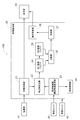
- An image display system 100 shown in FIG. 1 displays a captured image around a vehicle imaged by an imaging unit 10 mounted on the vehicle.
- the image display system 100 includes an imaging unit 10, an image control unit 20, and a display unit 30.
- the imaging unit 10 includes a camera using a CCD or the like, for example, and is mounted on the vehicle to image the periphery of the vehicle.
- the captured image input from the imaging unit 10 is output to the display unit 30 after image processing or the like is performed by the image control unit 20.
- the display unit 30 is provided in an internal space of the vehicle or the like, and displays a captured image captured by the imaging unit 10.
- the imaging unit 10, the image control unit 20, and the display unit 30 are wired or wirelessly connected.
- the image control unit 20 includes an image processing unit 21, a stationary object detection unit 22, a vehicle height control unit 23 (an example of an imaging range changing unit), a comparison unit 26, a determination unit 27, and a display processing unit 28.
- Each of these functional units is configured by a CPU that executes various processes, software having a memory as a core, or cooperation of hardware and software.
- the image processing unit 21 performs image processing for displaying the captured image acquired from the imaging unit 10 on the display unit 30.
- the captured image subjected to the image processing by the image processing unit 21 is output and displayed on the display unit 30 and also output to the stationary object detection unit 22.
- the stationary object detection unit 22 detects the stationary object included in the captured image input from the image processing unit 21 and the position of the stationary object in the captured image.
- the stationary object is an object that exists in the vicinity of the vehicle and does not change its own position.
- L, signs, poles P, and the like that exist on the ground and are stationary (features) are applicable.
- a stationary object included in the captured image is detected based on shape, luminance information, and the like.
- the lane marking L attached to the road surface can be detected using a known automatic recognition technique.
- the stationary object detection unit 22 detects a stationary object (for example, a lane marking L) by performing edge extraction from the captured image.
- the stationary object detection unit 22 detects a stationary object by extracting luminance change points (feature points) that are equal to or greater than a specified threshold.
- the stationary object detection unit 22 may detect one or more of these stationary objects in combination.
- the vehicle height control unit 23 is provided as an imaging range changing unit, and changes the imaging range of the imaging unit 10 when the vehicle is stopped.
- the vehicle height control unit 23 controls the vehicle height based on the detection value of the vehicle height sensor 50 provided in the vehicle.
- the imaging range of the imaging unit 10 is changed as shown in FIG.
- the vehicle height control unit 23 may control the vehicle height to be lower than that before the change.
- the vehicle height of the vehicle is changed up and down by using, for example, expansion and contraction of an air suspension of the vehicle or an electromagnetic suspension.
- the comparison unit 26 is connected to the determination unit 27, and the stationary object included in the captured image before the imaging range is changed by the vehicle height control unit 23 and the captured object after the imaging range is changed. And the difference value between them is calculated. Specifically, the image data relating to the position of the stationary object in the captured image output from the stationary object detection unit 22 is temporarily stored in the first image buffer 24 and the second image buffer 25, and two data are compared by the comparison unit 26. A difference value of the image data is calculated. The difference value of the image data is calculated based on the amount of change in position of a stationary object (for example, a contour portion) in the captured image.
- a stationary object for example, a contour portion
- the determination unit 27 determines whether the imaging unit 10 is abnormal based on the difference value calculated by the comparison unit 26. In the present embodiment, the determination unit 27 determines that there is an abnormality in the imaging unit 10 when the difference value is smaller than a predetermined threshold value. This is because when the difference value is smaller than a predetermined threshold value, the position change of the stationary object included in the captured image before and after the imaging range is changed hardly occurs, and the captured image freezes. Based on the high probability that
- the vehicle is provided with a vehicle speed sensor 40 that detects the moving speed.
- the vehicle speed sensor 40 is connected to the image control unit 20, and vehicle speed data is input from the vehicle speed sensor 40 to the image control unit 20.
- the image control unit 20 determines that the vehicle is in a moving state based on the speed data obtained from the vehicle speed sensor 40, the image control unit 20 does not execute a determination process on the captured image.
- the position detection and determination of the stationary object in the captured image is executed.
- the display processing unit 28 transmits a caution message to the display unit 30 when the determination unit 27 determines that the imaging unit 10 is abnormal when the difference value is smaller than a predetermined threshold value.
- the display processing unit 28 receives the abnormality determination signal from the determination unit 27, the display processing unit 28 outputs a warning message (notification message) and a warning message display instruction to the display unit 30.
- the caution message is stored in a ROM (not shown) of the display processing unit 28.
- the display processing unit 28 operates as a notification unit that notifies that the captured image is frozen and the imaging unit 10 is abnormal.
- the display unit 30 can perform, for example, a composite display (superimpose display) in which characters (caution messages) are superimposed on the display image, and the display processing unit 28 displays an instruction for a warning message and a superimpose display.
- the warning message is sent to the unit 30 and a superimpose message is displayed.
- step # 10 it is confirmed whether or not the vehicle is stopped based on the speed data from the vehicle speed sensor 40 (step # 10).
- step # 10 it is confirmed whether or not the vehicle is stopped based on the speed data from the vehicle speed sensor 40 (step # 10).
- the vehicle height control unit 23 controls the change of the imaging range (step # 11), and the captured image is displayed. Is input to the stationary object detection unit 22 (step # 12).
- the imaging range change control is continued until a predetermined number (a plurality of N) of captured images are captured, and the imaging range is changed (steps # 11 to 13).
- the capturing of the captured image in step # 13 may be a predetermined time instead of the predetermined number.
- the comparison unit 26 compares the first image and the second image (step # 14). Specifically, the comparison unit 26 calculates a difference value between the first image and the second image.
- the determination unit 27 may compare the average or total of all the difference values with a predetermined threshold value.
- the determination unit 27 detects the freeze of the captured image based on the difference value calculated by the comparison unit 26 (step # 15). Specifically, the determination unit 27 determines whether or not the difference value is equal to or less than a predetermined threshold value. When the determination unit 27 determines that the difference value is equal to or less than the threshold value (step # 15, Yes), a freeze is detected, and the determination unit 27 instructs the display processing unit 28 to display a warning message such as a caution message. Is transmitted, and a warning text is displayed on the display unit 30 (step # 16).
- the stationary object detection unit 22 detects the stationary object included in the captured image and the position of the stationary object, and the first image buffer 24 and the second image buffer 25 store the stationary object in the captured image of the stationary object. Only position data is temporarily stored.
- a stationary object is the lane marking L on the road surface shown by the display image of FIG. 3, for example.
- the stationary object detection unit 22 may detect the entire stationary object included in the captured image, or may detect a part of the stationary object. Specifically, the stationary object detection unit 22 may detect the edge of the stationary object and the position of the edge in the captured image. In that case, the determination unit 27 performs determination based on the position of the edge of the stationary object.
- the edge of the stationary object is, for example, the end of the lane marking L on the road surface shown in the display image of FIG.
- the determination based on the position of the edge of the stationary object may be performed by one of the edges of the stationary object, or may be performed by a line segment connecting a plurality of edges.
- the determination by the determination unit 27 based on the position of the edge or the like that is a part of the stationary object can reduce the amount of data used to detect abnormalities in consecutive captured images. it can.
- the portion of the stationary object included in the captured image that is continuous along the height direction of the vehicle may hardly change in position in the continuous captured image even when the captured image is normally displayed. For this reason, even if continuous captured images are normally displayed, it may occur that the determination unit 27 determines that the position of the stationary object in the captured image has not changed.
- the stationary object detection unit 22 detects the position of a non-parallel portion of the stationary object included in the captured image in the vehicle height direction.
- the portion of the stationary object that is not parallel to the height direction of the vehicle corresponds to, for example, a lane marking L on the road surface shown in FIG.
- a portion of the stationary object that is not parallel to the height direction of the vehicle is a portion in which the position in the captured image changes when the vehicle height increases and the imaging range is changed. For this reason, the determination unit 27 can reliably detect an abnormality in the imaging unit 10.
- the vehicle includes a vehicle illumination unit 60 that irradiates an imaging range. Therefore, the brightness of the vehicle illumination unit 60 may be changed before and after the imaging range is changed by the vehicle height control unit 23.
- the imaging unit 10 is provided at the rear of the vehicle and captures the rear of the vehicle, the brightness of the brake lamp or the like as the vehicle illumination unit 60 is changed (such as a brake lamp when the vehicle periphery is dark). Increase the brightness).
- the determination unit 27 can appropriately determine the state of the imaging unit 10.
- the abnormality of the imaging unit 10 can be detected more reliably.
- the vehicle illumination unit 60 is not limited to a brake lamp, and may be another illumination unit such as a headlamp.
- FIG. 1 An example in which the vehicle height control unit 23 is provided as the imaging range changing unit and the imaging range of the imaging unit 10 is changed by changing the vehicle height is shown. May change the imaging range of the imaging unit 10 by changing the elevation angle of the imaging unit 10 with respect to the imaging target.
- the imaging range changing unit may be configured to include a mechanism for changing the imaging range by changing the elevation angle of the imaging unit 10 instead of the vehicle height control unit 23, or the elevation range of the vehicle height control unit 23 and the imaging unit 10. And a mechanism for changing the position may be provided.
- the vehicle height control unit 23 changes the imaging range of the imaging unit 10 and the determination unit 27 performs the determination.
- the determination unit 27 determines that the captured image is frozen
- determination is performed by the determination unit 27 that changes the elevation angle of the image capturing unit 10
- the captured image is frozen by the determination unit 27.
- the imaging range of the imaging unit 10 is changed by changing the elevation angle of the imaging unit 10 in the reverse order, and then the imaging range of the imaging unit 10 is changed by the vehicle height control unit 23. Good.
- the comparison unit 26 compares the positions of the stationary objects in the captured images before and after the imaging range is changed, and calculates the difference value.
- the difference value may be calculated by comparing the captured images before and after the change (the entire captured image).
- the imaging unit 10 includes one camera has been described.
- the imaging unit 10 may include a plurality of cameras.
- the display processing unit 28 is provided as a notification unit and a warning text is displayed on the display unit 30 .
- the notification unit is not limited to the display processing unit 28 and A warning may be made using sound or light emitted from a speaker, a warning light, or the like provided in the device.
- the image display system 100 changes the luminance of the vehicle illumination unit 60 without changing the imaging range, and the luminance of the vehicle illumination unit 60 and the captured image before the luminance of the vehicle illumination unit 60 is changed.
- the difference value luminance difference
- the difference value may be calculated by comparing the captured image after the change is made with the comparison unit 26, and the determination unit 27 may determine whether the imaging unit 10 is abnormal based on the difference value.
- the present invention can be widely used in an image display system mounted on a moving body including a vehicle.
Landscapes
- Engineering & Computer Science (AREA)
- Mechanical Engineering (AREA)
- Multimedia (AREA)
- Chemical & Material Sciences (AREA)
- Combustion & Propulsion (AREA)
- Transportation (AREA)
- Signal Processing (AREA)
- Physics & Mathematics (AREA)
- General Physics & Mathematics (AREA)
- Closed-Circuit Television Systems (AREA)
- Image Processing (AREA)
Abstract
画像表示システムは、車両に搭載され、当該車両の周辺を撮像する撮像部と、撮像部によって撮像された撮像画像を表示する表示部と、車両の停止時に撮像部の撮像範囲を変更する撮像範囲変更部と、撮像範囲変更部によって撮像範囲が変更される前の撮像画像と撮像範囲が変更された後の撮像画像とを比較して両者の差分値を算出する比較部と、差分値に基づいて撮像部の異常の有無を判定する判定部と、を備える。
Description
本発明は、車両に搭載される撮像部によって撮像される撮像画像を表示部に表示する画像表示システムに関する。
自動車等の車両の運転を支援する装置として、車載された撮像部と、撮像部で撮像された画像が表示される表示部とを備える画像表示システムが用いられている。撮像部に不具合が生じて、表示部に表示される撮像画像が変化せずに固定した状態(以下、フリーズと呼ぶ)になる場合がある。
撮像画像にフリーズが発生したことを検出するために、車両が移動したときに取得される撮像部からの撮像画像の変化を監視する画像表示システムが存在する。例えば、特許文献1に記載の画像表示システムでは、撮像部から連続して出力される画像フレームの差異を検出する差異検出手段を備え、車両が走行中に連続する画像フレームに差異が検出されないときに表示画像がフリーズ状態であるとの判定を行う。
車両が走行中であると、表示画像のフリーズ判定を行うために用いられる撮像画像のフレーム数が多くなり、撮影画像全体のデータ量が増加する。フリーズ判定のためのデータ量を少なくするために、特許文献2に記載の画像表示システムでは、撮像画像の特定領域にフレーム毎に反転する白色または黒色の検出用画像を付加し、連続する撮像画像において特定領域に含まれる検出用画像として白色画像と黒色画像とが繰り返し含まれている場合に、撮像画像にフリーズが発生していないと判定する。
特許文献1の技術では、車両走行中に撮像部から出力されて連続する画像フレームに対して差異を検出するため、車載カメラによって撮像された画像データを一時記憶するために必要なバッファは大きくなり、回路コストが増大する。また、車両走行中でも、車両の周辺環境の変化が乏しく連続する撮像画像がほとんど変化しない場合には、撮像画像がフリーズ状態であると誤って判定されることがある。
一方、特許文献2の技術では、撮像画像がフリーズ状態であるか否かを判定するのに用いるデータ量は少ないが、カメラの撮像画像にフリーズ判定用の画像信号を付加する機能が別途必要となる。また、撮像画像自体に問題がない場合であっても、撮像画像に付加される信号が適正に表示されない場合等には撮像画像がフリーズであると誤って判断されることがある。
一方、特許文献2の技術では、撮像画像がフリーズ状態であるか否かを判定するのに用いるデータ量は少ないが、カメラの撮像画像にフリーズ判定用の画像信号を付加する機能が別途必要となる。また、撮像画像自体に問題がない場合であっても、撮像画像に付加される信号が適正に表示されない場合等には撮像画像がフリーズであると誤って判断されることがある。
そこで、簡素な構成によって撮像部の異常を確実に検出することができる画像表示システムが望まれている。
本発明に係る画像表示システムの特徴構成は、車両に搭載され、当該車両の周辺を撮像する撮像部と、前記撮像部によって撮像された撮像画像を表示する表示部と、前記車両の停止時に前記撮像部の撮像範囲を変更する撮像範囲変更部と、前記撮像範囲変更部によって前記撮像範囲が変更される前の撮像画像と前記撮像範囲が変更された後の撮像画像とを比較して両者の差分値を算出する比較部と、前記差分値に基づいて前記撮像部の異常の有無を判定する判定部と、を備える点にある。
本構成によれば、撮像範囲変更部を備え、車両停止中に撮像範囲が変更される前の撮像画像と前記撮像範囲が変更された後の撮像画像とを比較して撮像画像がフリーズであるか否かを判断する。つまり、車両停止中に意図的に撮像部の撮像範囲を変更し、撮像画像を確実に変化させた状態で撮像画像がフリーズであるか否かを判断する。これにより、画像表示システムにおいて、撮像画像がフリーズであるか否かの判断の精度が向上する。
また、車両が停止状態のときに撮像画像がフリーズであるか否かの判断が可能となるので、従来のように車両走行中に取得される撮影画像の大量の画像データを記憶する必要がない。
さらに、撮像範囲が変更される前後での撮像画像を比較する構成であるので、撮像画像には信号を付加する必要もなく、撮像画像自体の問題を検出することが可能となる。
したがって、簡素な構成によって撮像画像に発生したフリーズを確実に検出することができ、撮像部の異常の有無を適正に判定することができる。
また、車両が停止状態のときに撮像画像がフリーズであるか否かの判断が可能となるので、従来のように車両走行中に取得される撮影画像の大量の画像データを記憶する必要がない。
さらに、撮像範囲が変更される前後での撮像画像を比較する構成であるので、撮像画像には信号を付加する必要もなく、撮像画像自体の問題を検出することが可能となる。
したがって、簡素な構成によって撮像画像に発生したフリーズを確実に検出することができ、撮像部の異常の有無を適正に判定することができる。
本発明に係る画像表示システムの他の特徴構成は、前記判定部は、前記差分値が所定のしきい値よりも小さいときに前記撮像部に異常があると判定する点にある。
比較部によって算出される差分値が所定のしきい値よりも小さい場合には、異なる撮像画像において撮像対象の位置変化がほとんど発生しておらず、撮像画像にフリーズに発生している可能性が高い。そこで、本構成では、判定部は、差分値が所定のしきい値よりも小さいときに撮像部に異常があると判定する。これにより、撮像画像にフリーズが発生し撮像部に異常があることを確実に検知することができる。
本発明に係る画像表示システムの他の特徴構成は、前記撮像範囲変更部は、前記車両の車高を変えることで前記撮像範囲を変更する点にある。
本構成によれば、撮像範囲変更部は、車両の車高を変えることで撮像範囲を変更するので、車両のエンジン起動時等において、確実に撮像範囲を変更することができる。
本発明に係る画像表示システムの他の特徴構成は、前記撮像範囲変更部は、撮像対象に対する前記撮像部の仰角を変えることで前記撮像範囲を変更する点にある。
本構成によれば、撮像範囲変更部は、撮像対象に対する撮像装置の仰角を変えることで撮像範囲を変更するので、車両の位置を変化させる機構等を設けることなく、撮像範囲を変更することができる。
本発明に係る画像表示システムの他の特徴構成は、前記撮像画像に含まれる静止物及び当該静止物の前記撮像画像における位置を検出する静止物検出部をさらに備え、前記比較部は、前記静止物の位置に基づいて前記差分値を算出する点にある。
本構成によれば、撮像画像に含まれる静止物を検出する静止物検出部を備え、比較部が当該静止物の位置に基づいて差分値を算出するので、少ないデータ量に基づいて撮像部の異常の有無を判定することができる。
本発明に係る画像表示システムの他の特徴構成は、前記撮像範囲を照射する車両照明部をさらに備え、前記撮像範囲変更部によって前記撮像範囲が変更される前後は、前記車両照明部の輝度が変更される点にある。
夜間等において車両周辺が暗い場合には、撮像範囲が変更される前後に撮像画像の変化が検出できないことがある。そこで、本構成では、撮像範囲を照射する車両照明部をさらに備え、撮像範囲変更部によって撮像範囲が変更される前後は、前記車両照明部の輝度が変更される。車両周辺が暗く撮像画像が認識し難い場合には、車両照明部の輝度を上げる。反対に、車両照明部の輝度が高く撮像画像が認識し難い場合には、車両照明部の輝度を下げる。これにより、撮像画像が適正に認識されて、撮像画像がフリーズしているか否かの判定を適正に行うことができる。その結果、撮像部の異常を確実に検出することができる。
以下、本発明の一つの実施形態を図面に基づいて具体的に説明する。
図1に示す画像表示システム100は、車両に搭載された撮像部10によって撮像された車両周辺の撮像画像を表示するものである。
図1に示すように、画像表示システム100は、撮像部10と、画像制御部20と、表示部30と、を備える。撮像部10は、例えばCCD等が用いられたカメラを備え、車両に搭載されて車両の周辺を撮像する。撮像部10から入力された撮像画像は、画像制御部20によって画像処理等が行われた後に表示部30に出力される。表示部30は、車両の内部空間等に設けられ、撮像部10によって撮像された撮像画像を表示する。撮像部10、画像制御部20、及び表示部30は、有線接続又は無線接続されている。
図1に示すように、画像表示システム100は、撮像部10と、画像制御部20と、表示部30と、を備える。撮像部10は、例えばCCD等が用いられたカメラを備え、車両に搭載されて車両の周辺を撮像する。撮像部10から入力された撮像画像は、画像制御部20によって画像処理等が行われた後に表示部30に出力される。表示部30は、車両の内部空間等に設けられ、撮像部10によって撮像された撮像画像を表示する。撮像部10、画像制御部20、及び表示部30は、有線接続又は無線接続されている。
画像制御部20は、画像処理部21、静止物検出部22、車高制御部23(撮像範囲変更部の一例)、比較部26、判定部27、及び、表示処理部28を備える。これら各機能部は各種処理を実行するCPUやメモリを中核としたソフトウェア、又はハードウェアとソフトウェアとの協働により構成されている。画像処理部21は、撮像部10から取得された撮像画像を表示部30に表示するための画像処理を行う。画像処理部21によって画像処理された撮像画像は、表示部30に出力されて表示されるとともに、静止物検出部22にも出力される。静止物検出部22は、画像処理部21から入力された撮像画像に含まれる静止物及び当該静止物の撮像画像における位置を検出する。
ここで、静止物とは、車両の周辺に存在し、それ自体の位置が変化しない物体であり、静止物としては、例えば図3の表示画像に含まれる路面に付された区画線(白線)Lや、標識、ポールP等、地面上に存在し静止している物全般(地物)が該当する。撮像画像に含まれる静止物は、形状や輝度情報等に基づいて検出される。例えば、路面に付された区画線Lについては、公知の自動認識技術を用いて検出することができる。静止物検出部22は、一例として、撮像画像からエッジ抽出を行うことで静止物(例えば区画線L)を検出する。詳細には、静止物検出部22は、規定の閾値以上の輝度変化点(特徴点)を抽出して静止物を検出する。静止物検出部22は、これら静止物の1つまたは2つ以上を組み合わせて検出してもよい。
車高制御部23は、撮像範囲変更部として設けられており、車両の停止時に撮像部10の撮像範囲を変更する。車高制御部23は、車両に備えられた車高センサ50の検出値に基づいて車高を制御している。車高制御部23によって車両の車高が変更され、例えば車高が変更前よりも一定寸法高くなると、図3に示すように、撮像部10の撮像範囲が変更される。車高制御部23は、車両の車高が変更前よりも低くなるように制御してもよい。車両の車高は、例えば車両のエアサスペンションの伸縮や、電磁サスペンション等を用いて上下に変更される。
比較部26は、判定部27に接続されており、車高制御部23によって撮像範囲が変更される前の撮像画像に含まれる静止物と撮像範囲が変更された後の撮像画像の前記静止物とを比較して両者の差分値を算出する。具体的には、静止物検出部22から出力される撮像画像における静止物の位置に係る画像データが第1画像バッファ24及び第2画像バッファ25に一時的に記憶され、比較部26によって2つの画像データの差分値が算出される。画像データの差分値は、撮影画像における静止物(例えば、輪郭部分等)の位置変化量等に基づいて算出される。
判定部27は、比較部26によって演算された差分値に基づいて撮像部10の異常の有無を判定する。本実施形態では、判定部27は、差分値が所定のしきい値よりも小さいときに撮像部10に異常があると判定する。これは、差分値が所定のしきい値よりも小さい場合には、撮像範囲が変更される前後の撮像画像に含まれる静止物の位置変化がほとんど発生しておらず、撮像画像にフリーズに発生している可能性が高いことに基づく。
車両には、移動速度を検出する車速センサ40が設けられている。車速センサ40は画像制御部20に接続され、車両の速度データが車速センサ40から画像制御部20に入力される。画像制御部20は、車速センサ40から得た速度データを基に車両が移動状態であると判断した場合には撮像画像に対する判定処理を実行しない。反対に、車両が停止状態であると判断した場合には、撮像画像における静止物の位置検出及び判定を実行する。
表示処理部28は、判定部27において差分値が所定のしきい値よりも小さいときに撮像部10が異常であると判定された場合に表示部30に注意メッセージを送信して報知する。表示処理部28は、判定部27から異常判定の信号を受取ると、表示部30に注意メッセージ(報知メッセージ)及び注意メッセージの表示指示を出力する。注意メッセージは、表示処理部28の図示しないROMに記憶されている。表示処理部28は、撮像画像がフリーズして撮像部10に異常があることを報知する報知部として動作する。
表示部30は、例えば、表示画像に文字(注意メッセージ)を重ねて表示する合成表示(スーパーインポーズ表示)が可能であり、表示処理部28は、注意メッセージ及びスーパーインポーズ表示の指示を表示部30に送り、注意メッセージをスーパーインポーズ表示させる。
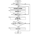
図2のフローチャートに基づき、画像表示システム100における撮影画像のフリーズ検出及び注意表示の手順を説明する。
まず、車速センサ40からの速度データに基づき車両が停止しているか否かが確認される(ステップ#10)。車速センサ40による速度データに基づき、車速が所定速度を越えて車両が走行中であると判断される場合(ステップ#10,No)には、以下の処理が実行されない。
まず、車速センサ40からの速度データに基づき車両が停止しているか否かが確認される(ステップ#10)。車速センサ40による速度データに基づき、車速が所定速度を越えて車両が走行中であると判断される場合(ステップ#10,No)には、以下の処理が実行されない。
車速がゼロまたは所定速度以下であり車両が停止していると判断されると(ステップ#10,Yes)、車高制御部23によって撮像範囲の変更制御が行われ(ステップ#11)、撮像画像が静止物検出部22に入力される(ステップ#12)。所定の枚数(複数であるN枚)の撮像画像が取り込まれるまで撮像範囲の変更制御が継続されて撮像範囲が変更される(ステップ#11~13)。ステップ#13による撮像画像の取り込みは、所定枚数に代えて所定時間であってもよい。
静止物検出部22に取り込まれたN枚の撮像画像データのうち、例えば第1画像バッファ24に先頭の画像データが記憶され、第2画像バッファ25に最後の画像データが記憶される(図3参照)。その後、比較部26において第1画像及び第2画像の比較が行われる(ステップ#14)。具体的には、比較部26において第1画像及び第2画像の差分値を算出する。なお、静止物検出部22に取り込まれたN枚の撮像画像データを第1画像バッファ24及び第2画像バッファ25に交互に記憶させ、比較部26が第1画像及び第2画像を比較する構成でもよい。この場合、判定部27は、全ての差分値の平均や合計等と所定のしきい値とを比較してもよい。
次に、比較部26によって算出された差分値に基づいて判定部27が撮像画像のフリーズを検出する(ステップ#15)。具体的には、判定部27によって差分値が所定のしきい値以下であるか否かが判断される。判定部27において差分値がしきい値以下と判定されると(ステップ#15,Yes)フリーズが検出されることとなり、判定部27から表示処理部28に注意メッセージ等の警告文の表示を指示する信号が送信され、表示部30に警告文が表示される(ステップ#16)。
本実施形態では、静止物検出部22においては、撮像画像に含まれる静止物及び当該静止物の位置が検出され、第1画像バッファ24及び第2画像バッファ25には、静止物の撮像画像における位置データのみが一時記憶される。静止物とは、例えば図3の表示画像に示される路面上の区画線Lである。
静止物検出部22は、撮像画像に含まれる静止物の全体を検出してもよいし、静止物の一部を検出するものでもよい。具体的には、静止物検出部22は、静止物の縁部及び当該縁部の撮像画像における位置を検出するものでもよい。その場合には、判定部27は、静止物の縁部の位置に基づく判定を行うことになる。静止物の縁部とは、例えば図3の表示画像に示される路面上の区画線Lの端部等である。なお、静止物の縁部の位置に基づく判定は、静止物の縁部の1つによって行っても良いし、複数の縁部どうしを結んだ線分によって行ってもよい。
このように、静止物の一部である縁部等の位置に基づいて判定部27による判定を行うことで、連続する撮像画像の異常を検出するために用いられるデータ量をより小さくすることができる。
撮像画像に含まれる静止物のうち車両の高さ方向に沿って連続する部分は、撮像画像が正常に表示される場合であっても連続する撮像画像において位置変化が殆ど生じないことがある。このため、連続する撮像画像が正常に表示されていても、判定部27において静止物の撮像画像における位置が変化していないと判定されることが起こり得る。
そのため、静止物検出部22は、撮像画像に含まれる静止物のうち車両の高さ方向に非平行な部分の位置を検出する方が好ましい。静止物のうち車両の高さ方向に非平行な部分とは、例えば図3に示される路面上の区画線L等が相当する。静止物のうち車両の高さ方向に非平行な部分は、車高が上下して撮像範囲が変更される際に撮像画像における位置が変化する部分である。このため、判定部27によって撮像部10の異常を確実に検出することができる。
夜間等において車両周辺が暗い場合には、撮像範囲を変更しても撮像画像の変化が検出されないことがある。図1に示すように、車両には撮像範囲を照射する車両照明部60を備えられている。そこで、車高制御部23によって撮像範囲が変更される前後は、車両照明部60の輝度が変更されるよう構成してもよい。例えば、撮像部10が車両の後部に設けられて車両後方を撮像するものである場合には、車両照明部60としてのブレーキランプ等の輝度が変更される(車両周辺が暗い場合にブレーキランプ等の輝度を大きくする)。これにより、夜間等においても比較部26による差分値の算出が確実なものとなり、判定部27が撮像部10の状態を適正に判定することができる。その結果、撮像部10の異常をより確実に検出することができる。なお、車両照明部60は、ブレーキランプに限定されず、ヘッドランプ等の他の照明部であってもよい。
〔別実施形態〕
(1)上記の実施形態においては、撮像範囲変更部として車高制御部23を設けて車両の車高を変えることで撮像部10の撮像範囲を変更する例を示したが、撮像範囲変更部は、撮像対象に対する撮像部10の仰角を変えることで撮像部10の撮像範囲を変更するものであってもよい。撮像範囲変更部は、車高制御部23に代えて撮像部10の仰角を変えて撮像範囲を変更する機構を備えて構成してもよいし、車高制御部23と、撮像部10の仰角を変える機構とが併設されていてもよい。
(1)上記の実施形態においては、撮像範囲変更部として車高制御部23を設けて車両の車高を変えることで撮像部10の撮像範囲を変更する例を示したが、撮像範囲変更部は、撮像対象に対する撮像部10の仰角を変えることで撮像部10の撮像範囲を変更するものであってもよい。撮像範囲変更部は、車高制御部23に代えて撮像部10の仰角を変えて撮像範囲を変更する機構を備えて構成してもよいし、車高制御部23と、撮像部10の仰角を変える機構とが併設されていてもよい。
撮像範囲変更部として両者が併設される場合には、例えば、最初に、車高制御部23によって撮像部10の撮像範囲を変更して判定部27による判定を行う。ここで、判定部27によって撮像画像がフリーズと判断された場合には、続けて撮像部10の仰角を変える判定部27による判定を行い、いずれにおいても判定部27によって撮像画像がフリーズとされた場合に撮像部10が異常であると判定する。このように、撮像範囲を変更する手段を変えて判定部27による判定を夫々行うことで、撮像部10の異常をより適正に検出することができる。上記の順序を逆にして、最初に、撮像部10の仰角を変えることで撮像部10の撮像範囲を変更し、その後に車高制御部23による撮像部10の撮像範囲の変更を行ってもよい。
(2)上記の実施形態においては、撮像範囲が変更される前後の撮像画像における静止物の位置を比較部26が比較して差分値を算出する例を示したが、比較部26は撮像範囲が変更される前後の撮像画像どうし(撮像画像全体)を比較して差分値を算出するものでもよい。
(3)上記の実施形態においては、画像制御部20に撮像部10及び表示部30を接続する例を示したが、画像制御部20を表示部30の内部に設け、撮像部10を表示部30に接続する構成であってもよい。
(4)上記の実施形態においては、撮像部10が1つのカメラを備えて構成する例を示したが、撮像部10は複数のカメラを備えて構成されていてもよい。
(5)上記の実施形態においては、報知部として表示処理部28を設けて表示部30に警告文を表示する例を示したが、報知部は、表示処理部28に限定されず、車両内に設けられるスピーカや警告灯等から発せられる音声や光を用いて警告するものでもよい。
(6)上記の実施形態では、撮像範囲が変更される前後は、車両照明部60の輝度を変える例を示した。これに代えて、画像表示システム100は、撮像範囲を変更せずに、車両照明部60の輝度を変更し、車両照明部60の輝度が変更される前の撮像画像と車両照明部60の輝度が変更された後の撮像画像とを比較部26によって比較して差分値(輝度差)を算出し、差分値に基づき判定部27が撮像部10の異常の有無を判定するものでもよい。
本発明は、車両を含む移動体に搭載される画像表示システムに広く用いることができる。
10 :カメラ(撮像部)
20 :画像制御部
21 :画像処理部
22 :静止物検出部
23 :車高制御部(撮像範囲変更部)
26 :比較部
27 :判定部
28 :表示処理部
30 :表示部
40 :車速センサ
50 :車高センサ
60 :車両照明部
100 :画像表示システム
L :区画線(静止物)
20 :画像制御部
21 :画像処理部
22 :静止物検出部
23 :車高制御部(撮像範囲変更部)
26 :比較部
27 :判定部
28 :表示処理部
30 :表示部
40 :車速センサ
50 :車高センサ
60 :車両照明部
100 :画像表示システム
L :区画線(静止物)
Claims (6)
- 車両に搭載され、当該車両の周辺を撮像する撮像部と、
前記撮像部によって撮像された撮像画像を表示する表示部と、
前記車両の停止時に前記撮像部の撮像範囲を変更する撮像範囲変更部と、
前記撮像範囲変更部によって前記撮像範囲が変更される前の撮像画像と前記撮像範囲が変更された後の撮像画像とを比較して両者の差分値を算出する比較部と、
前記差分値に基づいて前記撮像部の異常の有無を判定する判定部と、を備える画像表示システム。 - 前記判定部は、前記差分値が所定のしきい値よりも小さいときに前記撮像部に異常があると判定する請求項1に記載の画像表示システム。
- 前記撮像範囲変更部は、前記車両の車高を変えることで前記撮像範囲を変更する請求項1又は2に記載の画像表示システム。
- 前記撮像範囲変更部は、撮像対象に対する前記撮像部の仰角を変えることで前記撮像範囲を変更する請求項1~3のいずれか一項に記載の画像表示システム。
- 前記撮像画像に含まれる静止物及び当該静止物の前記撮像画像における位置を検出する静止物検出部をさらに備え、
前記比較部は、前記静止物の位置に基づいて前記差分値を算出する請求項1~4のいずれか一項に記載の画像表示システム。 - 前記撮像範囲を照射する車両照明部をさらに備え、
前記撮像範囲変更部によって前記撮像範囲が変更される前後は、前記車両照明部の輝度が変更される請求項1~5のいずれか一項に記載の画像表示システム。
Priority Applications (1)
| Application Number | Priority Date | Filing Date | Title |
|---|---|---|---|
| US16/302,849 US10576823B2 (en) | 2016-05-30 | 2017-03-24 | Image display system |
Applications Claiming Priority (2)
| Application Number | Priority Date | Filing Date | Title |
|---|---|---|---|
| JP2016107652A JP6642280B2 (ja) | 2016-05-30 | 2016-05-30 | 画像表示システム |
| JP2016-107652 | 2016-05-30 |
Publications (1)
| Publication Number | Publication Date |
|---|---|
| WO2017208586A1 true WO2017208586A1 (ja) | 2017-12-07 |
Family
ID=60478242
Family Applications (1)
| Application Number | Title | Priority Date | Filing Date |
|---|---|---|---|
| PCT/JP2017/011924 Ceased WO2017208586A1 (ja) | 2016-05-30 | 2017-03-24 | 画像表示システム |
Country Status (3)
| Country | Link |
|---|---|
| US (1) | US10576823B2 (ja) |
| JP (1) | JP6642280B2 (ja) |
| WO (1) | WO2017208586A1 (ja) |
Cited By (1)
| Publication number | Priority date | Publication date | Assignee | Title |
|---|---|---|---|---|
| JP2024054929A (ja) * | 2022-10-06 | 2024-04-18 | トヨタ自動車株式会社 | 遠隔システム |
Families Citing this family (3)
| Publication number | Priority date | Publication date | Assignee | Title |
|---|---|---|---|---|
| DE102017207792B4 (de) * | 2017-05-09 | 2025-10-16 | Aumovio Autonomous Mobility Germany Gmbh | Vorrichtung und Verfahren zum Prüfen einer Wiedergabe einer Videosequenz einer Spiegelersatzkamera |
| US11926263B2 (en) * | 2019-04-18 | 2024-03-12 | Mitsubishi Electric Corporation | Vehicle surrounding area image generation device, vehicle surrounding area display system, and vehicle surrounding area display method |
| JP7533798B2 (ja) * | 2021-10-19 | 2024-08-14 | 三菱電機ビルソリューションズ株式会社 | 画像解析システム |
Citations (4)
| Publication number | Priority date | Publication date | Assignee | Title |
|---|---|---|---|---|
| JP2004064440A (ja) * | 2002-07-29 | 2004-02-26 | Sumitomo Electric Ind Ltd | 撮像表示システム |
| JP2008252307A (ja) * | 2007-03-29 | 2008-10-16 | Denso Corp | 画像表示システム |
| JP2009005198A (ja) * | 2007-06-25 | 2009-01-08 | Hitachi Ltd | 映像監視システム |
| JP2013151191A (ja) * | 2012-01-24 | 2013-08-08 | Toyota Motor Corp | 車両周辺表示装置 |
Family Cites Families (13)
| Publication number | Priority date | Publication date | Assignee | Title |
|---|---|---|---|---|
| US6891563B2 (en) * | 1996-05-22 | 2005-05-10 | Donnelly Corporation | Vehicular vision system |
| US6681195B1 (en) * | 2000-03-22 | 2004-01-20 | Laser Technology, Inc. | Compact speed measurement system with onsite digital image capture, processing, and portable display |
| JP2004214970A (ja) | 2002-12-27 | 2004-07-29 | Sumitomo Electric Ind Ltd | 画像表示システム、画像表示方法及び画像処理装置 |
| US7787013B2 (en) * | 2004-02-03 | 2010-08-31 | Panasonic Corporation | Monitor system and camera |
| JP4613724B2 (ja) * | 2005-07-15 | 2011-01-19 | ソニー株式会社 | 撮像装置および撮像方法 |
| US8035503B2 (en) * | 2008-12-09 | 2011-10-11 | Delphi Technologies, Inc. | Vehicle location reminder system and method |
| US8994819B2 (en) * | 2011-02-04 | 2015-03-31 | Raytheon Company | Integrated optical detection system |
| JP6102930B2 (ja) * | 2011-10-14 | 2017-03-29 | オムロン株式会社 | 射影空間監視のための方法および装置 |
| EP2779151B1 (en) * | 2013-03-11 | 2018-05-16 | Renesas Electronics Europe Limited | Video output checker |
| KR102128756B1 (ko) * | 2014-02-17 | 2020-07-01 | 엘지이노텍 주식회사 | 자동차의 트렁크 개방 장치 및 방법과, 이 방법을 실행하기 위한 프로그램을 기록한 기록 매체 |
| JP6580872B2 (ja) * | 2015-06-05 | 2019-09-25 | 株式会社デンソーテン | 運転支援装置および運転支援方法 |
| WO2017045704A1 (en) * | 2015-09-15 | 2017-03-23 | Pepperl+Fuchs Gmbh | Apparatus and method for reliably determining the position of an object |
| US10057545B2 (en) * | 2016-05-19 | 2018-08-21 | GM Global Technology Operations LLC | Redundant video path for vehicle rear view camera system |
-
2016
- 2016-05-30 JP JP2016107652A patent/JP6642280B2/ja not_active Expired - Fee Related
-
2017
- 2017-03-24 WO PCT/JP2017/011924 patent/WO2017208586A1/ja not_active Ceased
- 2017-03-24 US US16/302,849 patent/US10576823B2/en active Active
Patent Citations (4)
| Publication number | Priority date | Publication date | Assignee | Title |
|---|---|---|---|---|
| JP2004064440A (ja) * | 2002-07-29 | 2004-02-26 | Sumitomo Electric Ind Ltd | 撮像表示システム |
| JP2008252307A (ja) * | 2007-03-29 | 2008-10-16 | Denso Corp | 画像表示システム |
| JP2009005198A (ja) * | 2007-06-25 | 2009-01-08 | Hitachi Ltd | 映像監視システム |
| JP2013151191A (ja) * | 2012-01-24 | 2013-08-08 | Toyota Motor Corp | 車両周辺表示装置 |
Cited By (2)
| Publication number | Priority date | Publication date | Assignee | Title |
|---|---|---|---|---|
| JP2024054929A (ja) * | 2022-10-06 | 2024-04-18 | トヨタ自動車株式会社 | 遠隔システム |
| JP7835144B2 (ja) | 2022-10-06 | 2026-03-25 | トヨタ自動車株式会社 | 遠隔システム |
Also Published As
| Publication number | Publication date |
|---|---|
| US10576823B2 (en) | 2020-03-03 |
| JP2017216518A (ja) | 2017-12-07 |
| JP6642280B2 (ja) | 2020-02-05 |
| US20190299782A1 (en) | 2019-10-03 |
Similar Documents
| Publication | Publication Date | Title |
|---|---|---|
| US9704404B2 (en) | Lane detection apparatus and operating method for the same | |
| JP5421072B2 (ja) | 接近物体検知システム | |
| JP2007172035A (ja) | 車載画像認識装置、車載撮像装置、車載撮像制御装置、警告処理装置、画像認識方法、撮像方法および撮像制御方法 | |
| JP6137081B2 (ja) | 車載機器 | |
| JP6723079B2 (ja) | 物体距離検出装置 | |
| JP5626147B2 (ja) | 車両接近物検知装置 | |
| WO2007111220A1 (ja) | 道路区画線検出装置 | |
| JP2018097766A (ja) | 画像処理装置、外界認識装置 | |
| WO2015118806A1 (ja) | 画像解析装置、および画像解析方法 | |
| JP6081034B2 (ja) | 車載カメラ制御装置 | |
| JP2012155612A (ja) | 車線検出装置 | |
| JP6642280B2 (ja) | 画像表示システム | |
| EP2600327A1 (en) | Obstacle detection system and method, and obstacle detection apparatus | |
| JP2015069381A (ja) | 車外環境認識装置 | |
| US11663834B2 (en) | Traffic signal recognition method and traffic signal recognition device | |
| US10853692B2 (en) | Vicinity supervising device and method for supervising vicinity of vehicle | |
| JP5353531B2 (ja) | 車両灯火認識装置及びプログラム | |
| JP6891082B2 (ja) | 物体距離検出装置 | |
| US20200331388A1 (en) | Image display system | |
| JP2018073049A (ja) | 画像認識装置、画像認識システム、及び画像認識方法 | |
| JP2005339234A (ja) | 前方車両監視装置 | |
| KR101850030B1 (ko) | 조도를 이용한 차선 변경 보조 방법 및 장치 | |
| JP2008244906A (ja) | 車両用表示装置 | |
| US10417505B2 (en) | Vehicle detection warning device and vehicle detection warning method | |
| WO2019013253A1 (ja) | 検出装置 |
Legal Events
| Date | Code | Title | Description |
|---|---|---|---|
| NENP | Non-entry into the national phase |
Ref country code: DE |
|
| 121 | Ep: the epo has been informed by wipo that ep was designated in this application |
Ref document number: 17806147 Country of ref document: EP Kind code of ref document: A1 |
|
| 122 | Ep: pct application non-entry in european phase |
Ref document number: 17806147 Country of ref document: EP Kind code of ref document: A1 |