WO2017204052A1 - 自律走行システム - Google Patents
自律走行システム Download PDFInfo
- Publication number
- WO2017204052A1 WO2017204052A1 PCT/JP2017/018525 JP2017018525W WO2017204052A1 WO 2017204052 A1 WO2017204052 A1 WO 2017204052A1 JP 2017018525 W JP2017018525 W JP 2017018525W WO 2017204052 A1 WO2017204052 A1 WO 2017204052A1
- Authority
- WO
- WIPO (PCT)
- Prior art keywords
- position information
- area
- work vehicle
- unit
- geodetic
- Prior art date
- Legal status (The legal status is an assumption and is not a legal conclusion. Google has not performed a legal analysis and makes no representation as to the accuracy of the status listed.)
- Ceased
Links
Images





Classifications
-
- G—PHYSICS
- G05—CONTROLLING; REGULATING
- G05D—SYSTEMS FOR CONTROLLING OR REGULATING NON-ELECTRIC VARIABLES
- G05D1/00—Control of position, course, altitude or attitude of land, water, air or space vehicles, e.g. using automatic pilots
- G05D1/02—Control of position or course in two dimensions
- G05D1/021—Control of position or course in two dimensions specially adapted to land vehicles
- G05D1/0268—Control of position or course in two dimensions specially adapted to land vehicles using internal positioning means
- G05D1/0274—Control of position or course in two dimensions specially adapted to land vehicles using internal positioning means using mapping information stored in a memory device
-
- A—HUMAN NECESSITIES
- A01—AGRICULTURE; FORESTRY; ANIMAL HUSBANDRY; HUNTING; TRAPPING; FISHING
- A01B—SOIL WORKING IN AGRICULTURE OR FORESTRY; PARTS, DETAILS, OR ACCESSORIES OF AGRICULTURAL MACHINES OR IMPLEMENTS, IN GENERAL
- A01B69/00—Steering of agricultural machines or implements; Guiding agricultural machines or implements on a desired track
-
- G—PHYSICS
- G05—CONTROLLING; REGULATING
- G05D—SYSTEMS FOR CONTROLLING OR REGULATING NON-ELECTRIC VARIABLES
- G05D1/00—Control of position, course, altitude or attitude of land, water, air or space vehicles, e.g. using automatic pilots
- G05D1/02—Control of position or course in two dimensions
- G05D1/021—Control of position or course in two dimensions specially adapted to land vehicles
- G05D1/0276—Control of position or course in two dimensions specially adapted to land vehicles using signals provided by a source external to the vehicle
- G05D1/0278—Control of position or course in two dimensions specially adapted to land vehicles using signals provided by a source external to the vehicle using satellite positioning signals, e.g. GPS
Definitions
- the present invention relates to an autonomous traveling system in which a work vehicle autonomously travels within a registered area registered in advance.
- the autonomous traveling system as described above is configured to acquire the current position of the work vehicle using, for example, a satellite positioning system, and autonomously travel the work vehicle along a target travel route or the like generated in the registration area. (For example, refer to Patent Document 1).
- the work vehicle is driven by the operator's operation or the like while acquiring position information of the work vehicle.
- region is acquired, and the area
- region For example, when the work vehicle is for agricultural work, a plurality of reference points that become corners of the farm field by using the corners of the farm field as reference points and running the work vehicle so as to go around the end side in the farm field. The location information of the point is acquired, and the region in the field surrounded by the line connecting the plurality of reference points is registered as the registration region.
- a registration area is usually registered in the farm field.
- an area including a road outside the farm field is registered as a registration area due to a registration error or the like, the work vehicle autonomously travels in an area where the autonomous traveling of the work vehicle should be prohibited. It will end up. Therefore, there is a need for a measure for preventing the work vehicle from traveling autonomously in a region where the work vehicle should be prohibited from traveling autonomously.
- the main problem of the present invention is to provide an autonomous traveling system that can prevent the autonomous traveling of the work vehicle in an area where the autonomous traveling of the working vehicle should be prohibited.
- a first characteristic configuration of the present invention is an autonomous traveling system that autonomously travels a work vehicle within a registered area registered in advance.
- a position information acquisition unit capable of acquiring position information of the work vehicle specified by a satellite positioning system;
- a map information acquisition unit capable of acquiring map information;
- An area identifying unit capable of identifying a traveling area based on a traveling locus of the work vehicle;
- a determination unit that determines whether the travel region specified by the region specifying unit includes a prohibited region in which autonomous traveling of the work vehicle is prohibited in the map information;
- a registration unit that registers the travel region as the registration region when the determination unit determines that the prohibited region is not included in the travel region.
- the position information acquisition unit acquires the position information of the work vehicle and causes the work vehicle to travel by maneuvering the operator. be able to.
- the region specifying unit can grasp the traveling locus of the working vehicle from the position information of the working vehicle acquired by the position information acquiring unit, and can specify the traveling region based on the traveling locus.
- the determination unit determines whether or not a prohibited area including a road or the like is included in the travel area, and the registration unit determines that the travel area does not include the prohibited area in the map information by the determination unit.
- the travel area is registered as a registration area.
- the determination unit determines that the prohibited area is included in the travel area, the travel area is not registered as the registration area. Therefore, it is possible to prevent the prohibited area including the road or the like from being included in the registration area, and it is possible to prevent the autonomous traveling of the work vehicle in the area where the autonomous traveling of the working vehicle should be prohibited.
- a second characteristic configuration of the present invention is an autonomous traveling system that autonomously travels a work vehicle within a pre-registered registration area, A position information acquisition unit capable of acquiring position information of the work vehicle specified by a satellite positioning system; A map information acquisition unit capable of acquiring map information; Whether or not the current position of the work vehicle acquired by the position information acquisition unit is within the registration area, and whether or not the work vehicle is in a prohibited area where autonomous travel of the work vehicle is prohibited in the map information.
- the determination unit registers the current position of the work vehicle acquired by the position information acquisition unit. It can be determined whether or not the current position of the work vehicle acquired by the position information acquisition unit is within the prohibited area in the map information.
- the autonomous traveling prohibition unit prohibits the autonomous traveling of the work vehicle by, for example, stopping the traveling of the work vehicle when the determination unit determines that the current position of the work vehicle is within the registration region and the prohibited region. be able to. Therefore, even if the work vehicle enters the prohibited area while the work vehicle is traveling autonomously, the autonomous travel of the work vehicle in the area where the autonomous travel of the work vehicle should be prohibited is prohibited by prohibiting the autonomous travel. Can be prevented.
- a third characteristic configuration of the present invention is that the position information acquisition unit is configured to be able to acquire the position information of the work vehicle by RTK positioning based on the position information of the base station.
- the position information acquisition unit can acquire the position information of the work vehicle by RTK positioning based on the position information of the base station, the position information acquisition unit can acquire accurate position information as the position information of the work vehicle.
- the position information acquisition unit can acquire accurate position information as the position information of the work vehicle.
- the position information acquisition unit can acquire position information of the work vehicle by a global geodetic system based on position information of a predetermined base station
- the map information is map information including position information by a Japanese geodetic system
- a geodetic conversion unit that performs geodetic conversion of the position information of the predetermined base station or the position information of the map information based on correction values of the world geodetic system and the Japanese geodetic system is provided.
- the position information acquisition unit can acquire the position information of the work vehicle by the world geodetic system, whereas the map information is the map information including the position information by the Japanese geodetic system. Since there is an error in the position information acquired between the world geodetic system and the Japanese geodetic system, if the above-described determination unit makes a determination with this error, an erroneous determination may occur. Therefore, by performing the geodetic conversion by the geodetic conversion unit, it is possible to eliminate the error and perform the determination by the above-described determination unit in a state where the error between the world geodetic system and the Japanese geodetic system is eliminated. Therefore, the determination by the above-described determination unit can be accurately performed, and the autonomous traveling of the work vehicle in the region where the autonomous traveling of the work vehicle should be prohibited can be appropriately prevented.
- a fifth characteristic configuration of the present invention includes a storage unit that stores the correction value in association with each region,
- the geodetic conversion unit is characterized in that the geodetic conversion is performed based on the correction value associated with an area to which the current position of the work vehicle belongs.
- a geodetic conversion part performs geodetic conversion based on the correction value matched with the area where the present position of a working vehicle belongs among the correction values memorize
- geodetic conversion can be performed appropriately according to the magnitude of the error that varies from region to region, and the position information of the predetermined base station and the position information of the map information are accurate when performing the determination by the determination unit described above. Position information can be acquired and more accurate determination can be performed.
- a sixth characteristic configuration of the present invention includes a mode execution unit capable of executing a correction mode for correcting an error in position information in the geodetic conversion by the geodetic conversion unit, A correction unit that corrects position information of the predetermined base station by independent positioning or RTK positioning based on position information of a base station different from the predetermined base station when the correction mode is executed by the mode execution unit; It is in the point characterized by providing.
- the correction unit When performing geodetic conversion by the geodetic conversion unit, it is conceivable that there is an error in the position information itself of a predetermined base station. Therefore, according to this configuration, the correction unit performs the positioning of a predetermined base station by single positioning or RTK positioning based on position information of a base station different from the predetermined base station when the correction mode is executed by the mode execution unit. Since the position information is corrected, there is no error in the position information of a predetermined base station, and accurate position information can be acquired. Therefore, the determination accuracy of the determination unit described above can be further improved, and autonomous traveling of the work vehicle in a region where the autonomous traveling of the work vehicle should be prohibited can be appropriately and more accurately prevented.
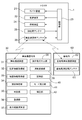
- this autonomous traveling system is a system for autonomously traveling a tractor 1 as a work vehicle in a registered area registered in advance.
- the autonomous traveling system includes a position information acquisition unit 32 that can acquire position information of the tractor 1, a map information acquisition unit 33 that can acquire map information, and the like.
- the communication terminal 30 is provided with an autonomous traveling system.
- the tractor 1 includes a vehicle body portion 2 on which a work machine 50 can be mounted on the rear side, the front portion of the vehicle body portion 2 is supported by a pair of left and right front wheels 3, and the rear portion of the vehicle body portion 2 is a pair of left and right rear wheels 4. It is supported.
- a bonnet 5 is disposed in the front part of the vehicle body 2, and an engine 6 as a drive source is accommodated in the bonnet 5.
- the engine 6 can be configured by, for example, a diesel engine, but is not limited thereto, and may be configured by, for example, a gasoline engine. Further, an electric motor may be employed as a drive source in addition to the engine 6 or instead of the engine 6.
- a cabin 7 for a driver to board is provided on the rear side of the bonnet 5, and a steering handle 8 for a driver to steer and a driver's driving seat 9 are provided in the cabin 7. It has been.
- the tractor 1 will be described as an example of a work vehicle.
- the work vehicle may be a walking type vehicle, a rice transplanter, a combiner, a civil engineering / architecture work device, a snowplow, or the like.
- a type work vehicle is also included.
- a three-point link mechanism including a pair of left and right lower links 10 and an upper link 11 is provided on the rear side of the vehicle body portion 2, and the working machine 50 can be mounted on the three-point link mechanism.
- a lifting device having a hydraulic device such as a lifting cylinder is provided on the rear side of the vehicle body 2, and this lifting device lifts and lowers the work implement 50 by lifting and lowering the three-point link mechanism. ing.
- FIG. 1 illustrates the case where a tilling device is mounted, but not only the tilling device but various working machines such as a plow and a fertilizer can be applied.
- the tractor 1 includes a governor device 21 that can adjust the rotational speed of the engine 6, a transmission device 22 that shifts the rotational driving force from the engine 6 and transmits it to the drive wheels, the governor device 21, A control unit 23 and the like that can control the device 22 are provided.
- the transmission 22 is configured by combining, for example, a main transmission composed of a hydraulic continuously variable transmission and an auxiliary transmission composed of a gear type multi-stage transmission.
- the tractor 1 not only allows the driver to travel in the cabin 7, but also allows the tractor 1 to travel autonomously based on a command from the wireless communication terminal 30 even if the driver does not enter the cabin 7. It is configured as possible.
- the tractor 1 includes a steering device 24, a positioning antenna 25, a wireless communication antenna 26, and the like, and autonomously acquires its current position information (position information of the vehicle body 2). It is configured to be able to run.
- the steering device 24 is provided, for example, in the middle of the rotation shaft of the steering handle 8 and is configured to be able to adjust the rotation angle (steering angle) of the steering handle 8.
- the control unit 23 controls the steering device 24, not only the straight traveling but also the turning angle of the steering handle 8 can be adjusted to a desired turning angle, and the turning turning with the desired turning radius can be performed.
- the positioning antenna 25 is configured to receive a signal from a positioning satellite 63 that constitutes a satellite positioning system (GNSS), for example.
- GNSS satellite positioning system
- the positioning antenna 25 is disposed on the upper surface of the roof 13 of the cabin 7.
- the radio communication antenna 26 is configured to be able to transmit and receive various signals to and from the radio communication terminal 30 and the like.
- the radio communication antenna 26 is disposed on the upper surface of the roof 13 of the cabin 7. As shown in FIG. 2, the signal received by the wireless communication antenna 26 can be input to the control unit 23, and the signal from the control unit 23 is transmitted to the wireless communication terminal 30 by the wireless communication antenna 26. It can be transmitted to the device 31 and the like.
- various positioning methods such as single positioning, DGPS (differential GPS positioning), and RTK positioning (real-time kinematic positioning) can be applied as positioning methods using the satellite positioning system.
- the tractor 1 serving as a mobile station includes a positioning antenna 25 and a base station positioning antenna 61.
- a base station 60 is provided.
- the base station 60 is arranged at a position that does not interfere with the traveling of the tractor 1, for example, around a farm field, the position information of the base station 60 is known, and the known position information is set in advance.
- the base station 60 includes a base station wireless communication device 62 that can transmit and receive various signals to and from the wireless communication antenna 26 of the tractor 1, and various information can be transmitted and received between the base station 60 and the tractor 1. It is configured to be possible.
- the carrier phase from the positioning satellite 63 is measured by both the base station 60 for which position information is set in advance and the positioning antenna 25 of the tractor 1 serving as a mobile station for which position information is to be obtained.
- Measurement data measured at the station 60 is transmitted from the base station wireless communication device 62 to the wireless communication antenna 26 of the tractor 1.
- the control unit 23 of the tractor 1 corrects the measurement data measured by the positioning antenna 25 using the measurement data measured by the base station 60, the preset position information of the base station 60, etc. 1 position information is obtained.
- the control unit 23 obtains, for example, latitude information / longitude information as position information of the tractor 1.
- the wireless communication terminal 30 is composed of, for example, a tablet personal computer having a touch panel, and can display various information on the touch panel. Various information can also be input by operating the touch panel.
- the autonomous traveling system is configured to register a registration area, generate a target traveling route in the registered registration area, and allow the tractor 1 to autonomously travel along the generated target traveling route.
- the wireless communication terminal 30 includes a location information acquisition unit 32, a map information acquisition unit 33, a region specification unit 34, a determination unit 35, a registration unit 36, and the like for registering a registration region.
- the wireless communication terminal 30 is provided with a travel route calculation unit 37 in order to generate a target travel route that indicates how the tractor 1 travels within the registered area.
- the control unit 23 provided in the tractor 1 is configured to transmit and receive various types of information to and from the wireless communication terminal 30 via wireless communication between the wireless communication antenna 26 and the wireless communication device 31. Yes.
- the wireless communication terminal 30 is configured to be able to transmit various types of information for causing the tractor 1 to autonomously travel, such as a target travel route, to the control unit 23 of the tractor 1.
- the control unit 23 of the tractor 1 controls the positioning antenna 25 so as to autonomously travel along the target travel route generated by the travel route calculation unit 37 in accordance with various information transmitted from the wireless communication terminal 30.
- the steering device 24 and the like can be controlled based on the current position information of the tractor 1 acquired from the received signal.
- the position information acquisition unit 32 is configured to be able to acquire the position information of the tractor 1 specified by the world geodetic system based on the position information of the known base station 60 by applying the RTK positioning of the satellite positioning system described above. Yes.
- the position information acquisition unit 32 may include the wireless communication device 31, the wireless communication antenna 26 of the tractor 1, and the control unit 23 of the tractor 1.
- the control unit 23 specifies the position information of the tractor 1 by the world geodetic system, and the position information acquisition unit 32 is connected to the radio communication antenna 26 of the tractor 1.
- the position information of the identified tractor 1 is acquired through wireless communication with the wireless communication device 31 of the wireless communication terminal 30.
- the map information that can be acquired by the map information acquisition unit 33 is map information including position information by the Japanese geodetic system.
- the map information acquisition unit 33 acquires map information based on the Japanese geodetic system by input by an operator's touch panel operation or wireless communication with an external device using the wireless communication device 31.
- the map information may include information indicating what kind of area each position coordinate is. For example, the map information is divided into a plurality of areas, and what kind of area each divided area is. May be included. Examples of the area include public roads, farm roads, parks, public facilities, and farm fields.
- the map information may include information indicating whether the vehicle is a permitted region where autonomous traveling by the tractor 1 is permitted or a prohibited region where autonomous traveling by the tractor 1 is prohibited.
- the operator may be able to arbitrarily set which area is the permitted area and which area is the prohibited area.
- the region specifying unit 34 is configured to be able to specify the travel region based on the travel locus of the tractor 1. Since the position information when the tractor 1 is traveled is acquired by the position information acquisition unit 32, the region specifying unit 34 obtains the travel trajectory of the tractor 1 from the acquired position information of the tractor 1, The traveling area of the tractor 1 is specified.
- the determination unit 35 includes part or all of the prohibited region where the autonomous traveling of the tractor 1 is prohibited in the map information acquired by the map information acquisition unit 33 in the travel region specified by the region specifying unit 34 Whether or not can be determined.
- the registration unit 36 is configured to be able to register the travel region as a registration region when the determination unit 35 determines that the travel region does not include the prohibited region. Thereby, a registration area can be registered without including a prohibition area that should normally prohibit autonomous traveling of the tractor 1 such as a public road.
- the travel area of the tractor 1 is based on the position information of the tractor 1 specified by the world geodetic system, whereas the map information is Japanese geodetic. It is acquired by the system. Therefore, since an error occurs between the position information acquired by the world geodetic system and the position information acquired by the Japanese geodetic system, the determination unit 35 performs the travel region of the tractor 1 by the world geodetic system and the map by the Japanese geodetic system. A simple comparison with information may result in a false determination.
- the wireless communication terminal 30 is provided with a geodetic conversion unit 39 that performs geodetic conversion of position information or map information of the base station 60 based on correction values of the world geodetic system and the Japanese geodetic system.
- the wireless communication terminal 30 includes a storage unit 40, a mode execution unit 41, and a correction unit 42 in order to perform geodetic conversion by the geodetic conversion unit 39.
- the storage unit 40 is configured to be able to store the correction values for the world geodetic system and the Japanese geodetic system in association with each region. Yes.
- the geodetic conversion part 39 is comprised so that geodetic conversion may be performed based on the correction value matched with the area where the present position of the tractor 1 belongs.
- the mode execution unit 41 is configured to be able to execute a correction mode for correcting an error in geodetic conversion by the geodetic conversion unit 39, and the correction unit 42 performs RTK positioning when the correction mode is executed by the mode execution unit 41.
- the position information of the base station 60 can be corrected.
- FIGS. 3 and 4 show the position information of the traveling area Q and the position of the map information such as the roads K1, K2 when the road is set as the traveling area Q when the roads K1, K2 are adjacent to the field. Information is shown.
- FIG. 3 shows position information of the travel region Q and the roads K1, K2, etc. before the geodetic conversion by the geodetic conversion unit 39 is performed.
- FIG. 4 shows position information of the travel region Q and the roads K1, K2, etc. after the geodetic conversion by the geodetic conversion unit 39 is performed.
- position information of roads K1, K2 adjacent to the periphery of the field is acquired as map information.
- the road K1 is a road that passes through the point P1 (x1, y1) and the point P2 (x2, y2), and position information that the road width is W1 is acquired.
- the road K2 is a road that passes through the point P3 (x3, y3) and the point P4 (x4, y5), and position information that the road width is W2 is acquired.
- the tractor 1 is driven by the operator's control, and the field specifying unit 34 specifies the field as the driving area Q based on the traveling locus of the tractor 1 at that time. For example, when the corner of the field is used as the reference point, the region specifying unit 34 determines the position information (u1, v1), (u2) at each of the plurality of reference points Q1, Q2, Q3, and Q4 from the travel locus of the tractor 1. , V2), (u3, v3), (u4, v4) are obtained, and an area surrounded by a line connecting a plurality of reference points Q1, Q2, Q3, Q4 is specified as the traveling area Q.
- the current position of the tractor 1 is (u6, v6), and the position of the base station 60 is (u0, v0).
- FIG. 3A shows a state shifted from the original relationship to the upper left side in the drawing
- FIG. 3B shows a state shifted from the original relationship to the lower right side in the drawing. .
- the geodetic conversion unit 39 performs geodetic conversion of the position information or map information of the base station 60 based on the correction values of the world geodetic system and the Japanese geodetic system. At this time, since the correction values of the world geodetic system and the Japanese geodetic system are associated with each region and stored in the storage unit 40, the geodetic conversion unit 39 determines which region the current position is based on the position information of the tractor 1 and the like. The position information of the base station 60 or the geodetic conversion of the map information is performed using the correction value associated with the area belonging to the current position. As a result, even if an error occurs due to the difference between the geodetic system of the world geodetic system and the Japanese geodetic system, the position information and map information of the base station 60 can be accurately acquired without the error. Can do.
- the geodetic conversion unit 39 performs geodetic conversion of the position information or the map information of the base station 60, not only errors due to different geodetic systems but also other errors can be considered. Considering this, more accurate position information is acquired.
- the position information is corrected for any point on the map.
- arbitrary positions on the map for example, reference points Q1, Q2, Q3, and Q4 that are corners of the field, the position of the base station 60, and the like can be used.
- the tractor 1 is moved to an arbitrary position on the map (for example, the reference point Q1), the position information of the tractor 1 at that time is acquired, and the arbitrary position on the map (for example, the reference point Q1) is the world
- the position information is corrected for an arbitrary point on the map so as to coincide with the position information of the tractor 1 specified by the geodetic system.
- the error between the latitude / longitude of an arbitrary point on the map and the latitude / longitude of the actual point can be corrected, and accurate map information can be acquired.
- the position information of the tractor 1 is specified using the position information of the base station 60, so it is considered that there is an error in the position of the base station 60 itself. Therefore, the mode execution unit 41 can execute a correction mode for correcting an error in position information in the geodetic conversion performed by the geodetic conversion unit 39, and the correction unit 42 can execute another correction mode when the correction mode is executed by the mode execution unit 41.
- the position information of the base station 60 is corrected by RTK positioning based on the base station 64.
- the correction unit 42 (corresponding to the base station position information acquisition unit) performs RTK positioning using the base station 60 as a mobile station and another base station 64 as a fixed station.
- the position information of the base station 60 is specified, the position information of the base station 60 is corrected, and the accurate position information of the base station 60 is acquired.
- another base station 64 various reference positions in which accurate position information is measured and set, such as an electronic reference point, a triangular point, a public reference point, and a virtual reference point (VRS), may be applied. it can.
- RTK positioning is used to acquire the position information of the base station 60
- various positioning methods such as single positioning and DGPS (differential GPS positioning) are applicable without being limited to the RTK positioning.
- the position information can be acquired in a stable state by the positioning hygiene system, such as when the position information of the base station 60 can be obtained by a predetermined number or more of the positioning satellites 63, the base station 60 acquired by each positioning satellite 63. Based on the average value of the position information, accurate position information of the base station 60 can be acquired.
- the set position information (x, y) (x11, y11) of another base station 64
- the geodetic conversion unit 39 performs geodetic conversion of the position information or map information of the base station 60 in consideration of the error of the map itself and the position information of the base station 60, as shown in FIG. In addition, it is possible to accurately acquire the position information of the travel region Q and the roads K1, K2, and the like.
- FIG. 4 shows a state where the geodetic conversion of the position information of the base station 60 is performed by the geodetic conversion unit 39. For each position information before geodetic conversion shown in FIG. 3, only the position obtained by geodetic conversion is shown as new position information as position information after geodetic conversion shown in FIG.
- the position information of the base station 60 is (u10, v10), and the position information at each of the plurality of reference points Q1, Q2, Q3, Q4 is Q1 (u11, v11), Q2 (u12, v12), Q3 (u13). , V13), Q4 (u14, v14), and the current position of the tractor 1 is indicated by (u16, v16).
- the geodetic conversion by the above-described geodetic conversion unit 39 can be performed before registering the registration area, but the timing can be changed as appropriate. Further, the correction of the position information of the base station 60 using the RTK positioning by the correction unit 42 can be performed at the beginning of the installation of the base station 60 or after the installation of the base station 60 separately from the geodetic conversion. For example, by correcting the position information of the base station 60 using RTK positioning by the correction unit 42 at the beginning of the installation of the base station 60, the position information of the base station 60 becomes accurate from the beginning of the installation of the base station 60. Thus, accurate position information of the tractor 1 can be acquired.
- the tractor 1 which is a work vehicle, is driven by the operator's operation in the field to be registered (step # 1).
- the corner of the field is used as a reference point of the registration area, and the tractor 1 is caused to travel at least in the vicinity of each of the corners of the field by running around the end in the field. Yes.
- the position information acquisition unit 32 acquires the position information of the tractor 1, obtains the travel locus of the tractor 1 when the tractor 1 is traveled, and acquires the position information of the reference point (step # 2).
- the corners of the field are set as the reference points Q1, Q2, Q3, and Q4 of the registration area, and the position information at each of the reference points Q1, Q2, Q3, and Q4 is acquired from the traveling locus of the tractor 1. ing.
- the region specifying unit 34 specifies the traveling region of the tractor 1 from the position information at each of the reference points Q1, Q2, Q3, and Q4 (step # 3). For example, in FIG. 4, an area surrounded by a line connecting the reference points Q1, Q2, Q3, and Q4 is specified as the traveling area Q.
- the identified travel area Q is compared with the acquired map information. For example, the travel area Q and the road information K1 and K2 are not adjacent to each other. If there is a deviation (for example, see FIG. 3), the geodetic conversion by the geodetic conversion unit 39 can be performed again. Thus, more accurate position information can be obtained by performing geodetic conversion by the geodetic conversion unit 39 again.
- the determination unit 35 determines whether or not the traveling region Q specified by the region specifying unit 34 includes a prohibited region, and the registration unit 36 registers the traveling region Q if the traveling region Q does not include the prohibited region. Register as an area (in the case of No in step # 4, step # 5). Moreover, the registration part 36 will not register a registration area, when the driving
- the traveling area Q is an area including the area Q6 surrounded by a dotted line in addition to the gray area Q5, the traveling area Q includes the prohibited area K, and the registration area is not registered.
- the registration area when the registration area is not registered, it can be displayed on the touch panel of the wireless communication terminal 30 so as to re-register the registration area.
- the autonomous traveling of the tractor 1 in the prohibited area K can be prevented by not registering the area including the prohibited area K as the registration area.
- a measure for preventing autonomous traveling of the tractor 1 in the prohibited region K not only a measure not to register the region including the prohibited region K as a registered region, but also when the tractor 1 is autonomously traveled, Since measures are taken to prevent the tractor 1 from traveling autonomously in the prohibited area K, the measures will be described.
- the determination unit 35 determines whether or not the current position of the tractor 1 acquired by the position information acquisition unit 32 is within the registration region, and whether or not the map unit is within the prohibited region K where the autonomous traveling of the tractor 1 is prohibited. Whether or not can be determined. As shown in FIG. 2, the wireless communication terminal 30 prohibits autonomous traveling of the tractor 1 when the determination unit 35 determines that the current position of the tractor 1 is within the registration area and the prohibited area K. An autonomous traveling prohibition unit 38 is provided.
- the control unit 23 acquires the current position of the tractor 1, and therefore the position information acquisition unit 32 via wireless communication between the wireless communication antenna 26 and the wireless communication device 31. Has acquired the current position of the tractor 1 (step # 11).
- the determination unit 35 determines whether or not the acquired current position of the tractor 1 is within the registration area, and whether or not the acquired current position of the tractor 1 is within the prohibited area K (step # 12, step # 13).
- step # 12 If the current position of the tractor 1 is outside the registration area T (see FIG. 8) as determined by the determination unit 35, the autonomous traveling prohibition unit 38 stops traveling and prohibits autonomous traveling (in step # 12). If No, step # 14).
- FIG. 8 shows a case where the prohibited area K exists in the registration area T. If the current position of the tractor 1 is within the registration region T, even if the current position of the tractor 1 is within the prohibited region K, the autonomous traveling prohibition unit 38 prohibits the autonomous traveling by stopping the traveling of the tractor 1 (Step S38). In the case of # 12 Yes, in the case of Yes in Step # 13, Step # 14).
- the autonomous traveling prohibiting unit 38 transmits an instruction signal for prohibiting the autonomous traveling of the tractor 1 to the wireless communication device 31 and the wireless communication antenna 26. Is transmitted to the control unit 23 of the tractor 1 via wireless communication. Based on the instruction signal from the autonomous traveling prohibition unit 38, the control unit 23 controls the governor device 21, the transmission 22 and the like so as to stop the traveling of the tractor 1 and prohibit autonomous traveling. At this time, it can be displayed on the touch panel of the wireless communication terminal 30, the monitor unit of the tractor 1, and the like that the traveling is stopped due to the prohibition of autonomous traveling.
- the autonomous traveling prohibition unit 38 continues the autonomous traveling of the tractor 1 when the current position of the tractor 1 is within the registration region T and the current position of the tractor 1 is outside the prohibited region K as determined by the determination unit 35. (In the case of Yes in Step # 12, in the case of No in Step # 13, Step # 15). At this time, an instruction signal is not transmitted from the autonomous traveling prohibition unit 38, and the autonomous traveling by the control unit 23 of the tractor 1 is continued.
- the autonomous traveling of the tractor 1 can be prohibited if it is within the prohibited area K.
- the tractor 1 stops traveling. Autonomous driving at K can be prevented.
- the determination unit 35 makes a determination every time the current position of the tractor 1 is acquired, the tractor 1 can be stopped traveling at an early stage when the tractor 1 enters the prohibited area K, and the autonomous operation in the prohibited area K can be performed. You can quickly stop running.
- the above-described two measures are taken as measures for preventing the tractor 1 from traveling autonomously in the prohibited region K. For example, only the measure not registering the region including the prohibited region K as a registered region. It is also possible to take only a measure of prohibiting autonomous traveling when the current position of the tractor 1 is within the prohibited region K when the tractor 1 is autonomously traveling.
- the position information acquisition unit 32 can acquire the position information of the tractor 1 by the world geodetic system based on the position information of the base station 60, whereas the map information is the position by the Japanese geodetic system. If it is map information including information and the geodetic system for acquiring the position information is different, but both the position information of the tractor 1 and the map information can be acquired by the same geodetic system by the world geodetic system or the Japanese geodetic system, Geodetic conversion by the conversion unit 39 may not be performed. In this case, apart from the geodetic conversion by the geodetic conversion unit 39, a configuration for eliminating an error in the map itself and an error in the position information of the base station 60 can be provided.
- the base station 60 is provided in order to obtain the position information of the tractor 1 by RTK positioning.
- another base station 64 is provided, so that the RTK is provided.
- the position information of the tractor 1 can also be acquired by positioning.
- another base station 64 not only RTK positioning but also various positioning methods such as DGPS (differential GPS positioning) can be applied.
- the wireless communication terminal 30 includes the position information acquisition unit 32, the map information acquisition unit 33, and the like of the autonomous traveling system according to the present invention
- the autonomous traveling system according to the present invention Where the position information acquisition unit 32, the map information acquisition unit 33, and the like are provided can be changed as appropriate.
- the position information acquisition unit 32 and the map information acquisition unit 33 of the autonomous traveling system according to the present invention can be provided in the control unit 23 of the tractor 1, and the autonomous control system according to the present invention can be provided in an external control device or the like. It is also possible to provide a travel system position information acquisition unit 32, a map information acquisition unit 33, and the like.
- the present invention can be applied to various autonomous traveling systems in which a work vehicle autonomously travels within a registered area registered in advance.
Landscapes
- Engineering & Computer Science (AREA)
- Radar, Positioning & Navigation (AREA)
- Remote Sensing (AREA)
- General Physics & Mathematics (AREA)
- Aviation & Aerospace Engineering (AREA)
- Physics & Mathematics (AREA)
- Life Sciences & Earth Sciences (AREA)
- Automation & Control Theory (AREA)
- Environmental Sciences (AREA)
- Soil Sciences (AREA)
- Mechanical Engineering (AREA)
- Guiding Agricultural Machines (AREA)
- Control Of Position, Course, Altitude, Or Attitude Of Moving Bodies (AREA)
- Navigation (AREA)
Abstract
本来なら作業車両の自律走行を禁止すべき領域における作業車両の自律走行を阻止することができる自律走行システムの提供。 衛星測位システムにより特定される作業車両1の位置情報を取得可能な位置情報取得部32と、地図情報を取得可能な地図情報取得部33と、作業車両1の走行軌跡に基づいて走行領域を特定可能な領域特定部34と、領域特定部34により特定された走行領域が地図情報において作業車両1の自律走行が禁止される禁止領域を含むか否かを判定する判定部35と、判定部35により走行領域に禁止領域が含まれないと判定される場合に走行領域を登録領域として登録する登録部36と、を備える。
Description
本発明は、予め登録された登録領域内において作業車両を自律走行させる自律走行システムに関する。
上記のような自律走行システムは、例えば、衛星測位システムを用いて作業車両の現在位置を取得し、登録領域内に生成される目標走行経路等に沿って作業車両を自律走行させるように構成されている(例えば、特許文献1参照。)。
登録領域の登録については、例えば、登録対象となる領域において、作業車両の位置情報を取得しながら、作業者の操縦等により作業車両を走行させる。そして、登録領域を登録するための基準となる複数の基準地点の夫々における位置情報を取得し、それら複数の基準地点から特定される領域を登録領域として登録している。例えば、作業車両が農作業用である場合には、圃場の角部等を基準地点とし、圃場内の端部側を周回するように作業車両を走行させて、圃場の角部となる複数の基準地点の位置情報を取得し、それら複数の基準地点を結ぶ線にて囲まれた圃場内の領域を登録領域として登録している。
上述の如く、例えば、作業車両が農作業用である場合には、通常、圃場内に登録領域が登録されることになる。しかしながら、登録ミス等により、圃場外の道路等を含む領域を登録領域として登録してしまうと、圃場外の道路等、本来なら作業車両の自律走行を禁止すべき領域で作業車両を自律走行させてしまうことになる。そこで、作業車両の自律走行を禁止すべき領域における作業車両の自律走行を阻止するための対策が求められている。
この実情に鑑み、本発明の主たる課題は、本来なら作業車両の自律走行を禁止すべき領域における作業車両の自律走行を阻止することができる自律走行システムを提供する点にある。
本発明の第1特徴構成は、予め登録された登録領域内において作業車両を自律走行させる自律走行システムであって、
衛星測位システムにより特定される前記作業車両の位置情報を取得可能な位置情報取得部と、
地図情報を取得可能な地図情報取得部と、
前記作業車両の走行軌跡に基づいて走行領域を特定可能な領域特定部と、
前記領域特定部により特定された走行領域が前記地図情報において前記作業車両の自律走行が禁止される禁止領域を含むか否かを判定する判定部と、
前記判定部により前記走行領域に前記禁止領域が含まれないと判定される場合に前記走行領域を前記登録領域として登録する登録部と、を備えることを特徴とする点にある。
衛星測位システムにより特定される前記作業車両の位置情報を取得可能な位置情報取得部と、
地図情報を取得可能な地図情報取得部と、
前記作業車両の走行軌跡に基づいて走行領域を特定可能な領域特定部と、
前記領域特定部により特定された走行領域が前記地図情報において前記作業車両の自律走行が禁止される禁止領域を含むか否かを判定する判定部と、
前記判定部により前記走行領域に前記禁止領域が含まれないと判定される場合に前記走行領域を前記登録領域として登録する登録部と、を備えることを特徴とする点にある。
本構成によれば、登録領域を登録する場合に、例えば、登録対象となる領域において、位置情報取得部にて作業車両の位置情報を取得しながら、作業者の操縦等により作業車両を走行させることができる。この作業車両の走行により、領域特定部が、位置情報取得部にて取得された作業車両の位置情報から作業車両の走行軌跡を把握し、その走行軌跡に基づいて走行領域を特定することができる。そして、判定部は、道路等を含む禁止領域が走行領域に含まれている否かを判定し、登録部が、判定部により走行領域に地図情報における禁止領域が含まれないと判定される場合に走行領域を登録領域として登録する。これにより、判定部により走行領域に禁止領域が含まれていると判定される場合には、走行領域が登録領域として登録されない。よって、道路等を含む禁止領域が登録領域に含まれることを防止することができ、本来なら作業車両の自律走行を禁止すべき領域における作業車両の自律走行を阻止することができる。
本発明の第2特徴構成は、予め登録された登録領域内において作業車両を自律走行させる自律走行システムであって、
衛星測位システムにより特定される前記作業車両の位置情報を取得可能な位置情報取得部と、
地図情報を取得可能な地図情報取得部と、
前記位置情報取得部により取得された前記作業車両の現在位置が前記登録領域内であるか否か、及び、前記地図情報において前記作業車両の自律走行が禁止される禁止領域内であるか否かを判定する判定部と、
前記判定部により前記作業車両の現在位置が前記登録領域内で且つ前記禁止領域内であると判定された場合に前記作業車両の自律走行を禁止する自律走行禁止部と、を備えることを特徴とする点にある。
衛星測位システムにより特定される前記作業車両の位置情報を取得可能な位置情報取得部と、
地図情報を取得可能な地図情報取得部と、
前記位置情報取得部により取得された前記作業車両の現在位置が前記登録領域内であるか否か、及び、前記地図情報において前記作業車両の自律走行が禁止される禁止領域内であるか否かを判定する判定部と、
前記判定部により前記作業車両の現在位置が前記登録領域内で且つ前記禁止領域内であると判定された場合に前記作業車両の自律走行を禁止する自律走行禁止部と、を備えることを特徴とする点にある。
本構成によれば、作業車両を自律走行させる場合に、位置情報取得部にて作業車両の現在位置を取得するので、判定部は、位置情報取得部により取得された作業車両の現在位置が登録領域内であるか否か、及び、位置情報取得部により取得された作業車両の現在位置が地図情報における禁止領域内であるか否かを判定することができる。そして、自律走行禁止部は、判定部により作業車両の現在位置が登録領域内で且つ禁止領域内であると判定された場合に、作業車両を走行停止させる等により作業車両の自律走行を禁止することができる。よって、作業車両を自律走行させているときに作業車両が禁止領域に侵入しても、その自律走行を禁止することで、本来なら作業車両の自律走行を禁止すべき領域における作業車両の自律走行を阻止することができる。
本発明の第3特徴構成は、前記位置情報取得部は、基地局の位置情報に基づいてRTK測位により前記作業車両の位置情報を取得可能に構成されていることを特徴とする点にある。
本構成によれば、位置情報取得部は、基地局の位置情報に基づいてRTK測位により作業車両の位置情報を取得できるので、作業車両の位置情報として正確な位置情報を取得できる。これにより、作業車両の自律走行を適切に行うことができるだけでなく、上述の判定部による判定も正確に行うことができ、本来なら作業車両の自律走行を禁止すべき領域における作業車両の自律走行を適切に阻止することができる。
本発明の第4特徴構成は、前記位置情報取得部は所定の基地局の位置情報に基づいて世界測地系により前記作業車両の位置情報を取得可能であり、
前記地図情報は日本測地系による位置情報を含む地図情報であって、
世界測地系と日本測地系との補正値に基づいて前記所定の基地局の位置情報又は前記地図情報の位置情報の測地変換を行う測地変換部を備えることを特徴とする点にある。
前記地図情報は日本測地系による位置情報を含む地図情報であって、
世界測地系と日本測地系との補正値に基づいて前記所定の基地局の位置情報又は前記地図情報の位置情報の測地変換を行う測地変換部を備えることを特徴とする点にある。
本構成によれば、位置情報取得部が世界測地系により作業車両の位置情報を取得可能であるのに対して、地図情報は日本測地系による位置情報を含む地図情報となっている。世界測地系と日本測地系との間で取得される位置情報に誤差があるので、この誤差が有るまま上述の判定部が判定を行うと、誤判定となる可能性がある。そこで、測地変換部による測地変換を行うことで、その誤差を無くし、世界測地系と日本測地系との間での誤差を無くした状態で上述の判定部による判定を行うことができる。よって、上述の判定部による判定を正確に行うことができ、本来なら作業車両の自律走行を禁止すべき領域における作業車両の自律走行を適切に阻止することができる。
本発明の第5特徴構成は、前記補正値を地域毎に対応付けて記憶する記憶部を備え、
前記測地変換部は、前記作業車両の現在位置が属する地域に対応付けられた前記補正値に基づいて前記測地変換を行うことを特徴とする点にある。
前記測地変換部は、前記作業車両の現在位置が属する地域に対応付けられた前記補正値に基づいて前記測地変換を行うことを特徴とする点にある。
世界測地系と日本測地系との間での誤差の大きさは地域によって異なる。そこで、本構成によれば、測地変換部は、記憶部に記憶された補正値のうち、作業車両の現在位置が属する地域に対応付けられた補正値に基づいて測地変換を行う。これにより、地域毎で異なる誤差の大きさに応じて適切に測地変換を行うことができ、上述の判定部による判定を行うに当たり、所定の基地局の位置情報及び地図情報の位置情報について正確な位置情報を取得でき、より正確な判定を行うことができる。
本発明の第6特徴構成は、前記測地変換部による前記測地変換における位置情報の誤差を補正する補正モードを実行可能なモード実行部を備え、
前記モード実行部により前記補正モードが実行されたときに単独測位又は前記所定の基地局とは別の基地局の位置情報に基づくRTK測位により前記所定の基地局の位置情報を補正する補正部を備えることを特徴とする点にある。
前記モード実行部により前記補正モードが実行されたときに単独測位又は前記所定の基地局とは別の基地局の位置情報に基づくRTK測位により前記所定の基地局の位置情報を補正する補正部を備えることを特徴とする点にある。
測地変換部による測地変換を行うに当たり、所定の基地局の位置情報自体に誤差があることも考えられる。そこで、本構成によれば、補正部が、モード実行部により補正モードが実行されたときに単独測位又は所定の基地局とは別の基地局の位置情報に基づくRTK測位により所定の基地局の位置情報を補正するので、所定の基地局の位置情報の誤差をも無くし、正確な位置情報を取得することができる。よって、上述の判定部の判定精度をより向上することができ、本来なら作業車両の自律走行を禁止すべき領域における作業車両の自律走行を適切に且つより精度よく阻止することができる。
本発明に係る自律走行システムの実施形態を図面に基づいて説明する。
この自律走行システムは、図1に示すように、予め登録された登録領域内において作業車両としてのトラクタ1を自律走行させるためのシステムである。自律走行システムは、図2に示すように、トラクタ1の位置情報を取得可能な位置情報取得部32、地図情報を取得可能な地図情報取得部33等を備えており、この実施形態では、無線通信端末30に自律走行システムが備えられている。
この自律走行システムは、図1に示すように、予め登録された登録領域内において作業車両としてのトラクタ1を自律走行させるためのシステムである。自律走行システムは、図2に示すように、トラクタ1の位置情報を取得可能な位置情報取得部32、地図情報を取得可能な地図情報取得部33等を備えており、この実施形態では、無線通信端末30に自律走行システムが備えられている。
まず、図1に基づいてトラクタ1について説明する。
このトラクタ1は、後方側に作業機50を装着可能な車体部2を備え、車体部2の前部が左右一対の前輪3で支持され、車体部2の後部が左右一対の後輪4で支持されている。車体部2の前部にはボンネット5が配置され、そのボンネット5内に駆動源としてのエンジン6が収容されている。エンジン6は、例えばディーゼルエンジンにより構成することができるが、これに限るものではなく、例えばガソリンエンジンにより構成してもよい。また、駆動源としてエンジン6に加えて、或いはエンジン6に代えて、電気モータを採用してもよい。ボンネット5の後方側には、運転者が搭乗するためのキャビン7が備えられ、そのキャビン7内には、運転者が操向操作するためのステアリングハンドル8、運転者の運転座席9等が備えられている。なお、本実施形態では作業車両としてトラクタ1を例に説明するが、作業車両としては、トラクタの他、田植機、コンバイン、土木・建築作業装置、除雪車等、乗用型作業車両に加え、歩行型作業車両も含まれる。
このトラクタ1は、後方側に作業機50を装着可能な車体部2を備え、車体部2の前部が左右一対の前輪3で支持され、車体部2の後部が左右一対の後輪4で支持されている。車体部2の前部にはボンネット5が配置され、そのボンネット5内に駆動源としてのエンジン6が収容されている。エンジン6は、例えばディーゼルエンジンにより構成することができるが、これに限るものではなく、例えばガソリンエンジンにより構成してもよい。また、駆動源としてエンジン6に加えて、或いはエンジン6に代えて、電気モータを採用してもよい。ボンネット5の後方側には、運転者が搭乗するためのキャビン7が備えられ、そのキャビン7内には、運転者が操向操作するためのステアリングハンドル8、運転者の運転座席9等が備えられている。なお、本実施形態では作業車両としてトラクタ1を例に説明するが、作業車両としては、トラクタの他、田植機、コンバイン、土木・建築作業装置、除雪車等、乗用型作業車両に加え、歩行型作業車両も含まれる。
車体部2の後方側には、左右一対のロアリンク10とアッパリンク11とからなる3点リンク機構が備えられ、その3点リンク機構に作業機50が装着可能に構成されている。車体部2の後方側には、図示は省略するが、昇降シリンダ等の油圧装置を有する昇降装置が備えられ、この昇降装置が、3点リンク機構を昇降させることで、作業機50を昇降させている。
ここで、作業機50について、図1では、耕耘装置を装着した場合を例示しているが、耕耘装置に限らず、プラウ、施肥装置等、各種の作業機を適用することができる。
トラクタ1には、図2に示すように、エンジン6の回転速度を調整可能なガバナ装置21、エンジン6からの回転駆動力を変速して駆動輪に伝達する変速装置22、ガバナ装置21および変速装置22を制御可能な制御部23等が備えられている。変速装置22は、例えば、油圧式無段変速装置からなる主変速装置とギヤ式多段変速装置からなる副変速装置とを組み合わせて構成されている。
このトラクタ1は、運転者がキャビン7内に搭乗して走行できるだけでなく、キャビン7内に運転者が搭乗しなくても、無線通信端末30からの指令等に基づいて、トラクタ1を自律走行可能に構成している。
トラクタ1は、図2に示すように、操舵装置24、測位用アンテナ25、無線通信用アンテナ26等を備えており、自己の現在位置情報(車体部2の位置情報)を取得しながら、自律走行可能に構成されている。
操舵装置24は、例えば、ステアリングハンドル8の回転軸の途中部に備えられ、ステアリングハンドル8の回転角度(操舵角)を調整可能に構成されている。制御部23が操舵装置24を制御することで、直進走行だけでなく、ステアリングハンドル8の回転角度を所望の回転角度に調整して、所望の旋回半径での旋回走行も行える。
測位用アンテナ25は、図1に示すように、例えば、衛星測位システム(GNSS)を構成する測位衛星63からの信号を受信するように構成されている。測位用アンテナ25は、キャビン7のルーフ13の上面に配置されている。
無線通信用アンテナ26は、無線通信端末30等との間で各種の信号を送受信可能に構成されている。無線通信用アンテナ26は、キャビン7のルーフ13の上面に配置されている。無線通信用アンテナ26にて受信した信号は、図2に示すように、制御部23に入力可能であり、制御部23からの信号は、無線通信用アンテナ26にて無線通信端末30の無線通信装置31等に送信可能に構成されている。
ここで、衛星測位システムを用いた測位方法としては、単独測位、DGPS(ディファレンシャルGPS測位)、RTK測位(リアルタイムキネマティック測位)等の各種の測位方法を適用することができる。
この実施形態では、RTK測位を適用しており、図1及び図2に示すように、移動局となるトラクタ1に測位用アンテナ25を備えるのに加えて、基地局測位用アンテナ61を備えた基地局60が備えられている。基地局60は、例えば、圃場の周囲等、トラクタ1の走行の邪魔にならない位置に配置されており、基地局60の位置情報は既知であり、その既知の位置情報が予め設定されている。基地局60には、トラクタ1の無線通信用アンテナ26との間で各種の信号を送受信可能な基地局無線通信装置62が備えられ、基地局60とトラクタ1との間で各種の情報が送受信可能に構成されている。
RTK測位では、予め位置情報が設定されている基地局60と、位置情報を求める対象の移動局となるトラクタ1の測位用アンテナ25との両方で測位衛星63からの搬送波位相を測定し、基地局60にて測定した測定データ等を基地局無線通信装置62からトラクタ1の無線通信用アンテナ26に送信している。トラクタ1の制御部23は、測位用アンテナ25にて測定した測定データを、基地局60にて測定した測定データや予め設定されている基地局60の位置情報等を用いて補正して、トラクタ1の位置情報を求めている。制御部23は、トラクタ1の位置情報として、例えば、緯度情報・経度情報を求めている。
次に、図2に基づいて、無線通信端末30に備えられた自律走行システムについて説明する。
無線通信端末30は、例えば、タッチパネルを有するタブレット型のパーソナルコンピュータ等から構成され、各種情報をタッチパネルに表示可能であり、タッチパネルを操作することで、各種の情報も入力可能となっている。
無線通信端末30は、例えば、タッチパネルを有するタブレット型のパーソナルコンピュータ等から構成され、各種情報をタッチパネルに表示可能であり、タッチパネルを操作することで、各種の情報も入力可能となっている。
自律走行システムは、登録領域の登録を行い、その登録された登録領域内に目標走行経路を生成し、その生成された目標走行経路に沿ってトラクタ1を自律走行可能に構成されている。
無線通信端末30には、登録領域を登録するために、位置情報取得部32、地図情報取得部33、領域特定部34、判定部35、登録部36等が備えられている。また、登録された登録領域内にトラクタ1をどのように走行させるかを示す目標走行経路を生成するために、無線通信端末30には走行経路演算部37が備えられている。
トラクタ1に備えられた制御部23は、無線通信用アンテナ26と無線通信装置31との間での無線通信を介して、無線通信端末30との間で各種の情報を送受信可能に構成されている。無線通信端末30は、目標走行経路等、トラクタ1を自律走行させるための各種の情報をトラクタ1の制御部23に送信可能に構成されている。トラクタ1の制御部23は、無線通信端末30から送信された各種の情報に応じて、走行経路演算部37にて生成された目標走行経路に沿って自律走行するように、測位用アンテナ25の受信信号から取得するトラクタ1の現在位置情報に基づいて操舵装置24等を制御可能に構成されている。
位置情報取得部32は、上述の衛星測位システムのRTK測位を適用して、既知の基地局60の位置情報に基づいて世界測地系により特定されるトラクタ1の位置情報を取得可能に構成されている。ここで、位置情報取得部32は、無線通信装置31、トラクタ1の無線通信用アンテナ26、及び、トラクタ1の制御部23を含めて構成することもできる。上述の衛星測位システムのRTK測位を適用することで、制御部23では、世界測地系によりトラクタ1の位置情報が特定されており、位置情報取得部32は、トラクタ1の無線通信用アンテナ26と無線通信端末30の無線通信装置31との間での無線通信を介して、特定されたトラクタ1の位置情報を取得している。
地図情報取得部33が取得可能な地図情報は、日本測地系による位置情報を含む地図情報となっている。地図情報取得部33は、作業者のタッチパネルの操作による入力や無線通信装置31を用いた外部装置との無線通信により、日本測地系による地図情報を取得している。地図情報には、各位置座標がどのような領域であるかを示す情報が含まれていてもよく、例えば、地図情報は複数の領域に分割され、各分割領域がどのような領域であるかを示す情報が含まれていてよい。領域としては、例えば、公道、農道、公園、公共施設、圃場が例示される。また、地図情報には、トラクタ1による自律走行が許可される許可領域であるか、トラクタ1による自律走行が禁止される禁止領域であるかの情報が含まれていてよく、その場合、圃場は許可領域として設定され、圃場以外(公道、農道、公園、公共施設等)は禁止領域として設定される。何れの領域を許可領域とし、何れの領域を禁止領域とするかは作業者が任意に設定可能であってもよい。但し、安全性の観点から、圃場以外の領域を許可領域に設定するにあたっては一定の制限が課せられることが望ましく、例えば地図情報上圃場でないとしても実際は圃場である等、地図上の領域と実際の領域との間に相違が存在する場合に、その領域を圃場に変更することで、許可領域として設定可能となることが望ましい。
登録領域を登録する場合には、例えば、作業者の操縦によりトラクタ1を走行させ、そのときのトラクタ1の走行領域に基づいて登録領域を登録可能としている。そこで、領域特定部34は、トラクタ1の走行軌跡に基づいて走行領域を特定可能に構成されている。トラクタ1を走行させたときの位置情報は、位置情報取得部32にて取得しているので、領域特定部34は、その取得されたトラクタ1の位置情報からトラクタ1の走行軌跡を求めて、トラクタ1の走行領域を特定している。
判定部35は、領域特定部34にて特定された走行領域が地図情報取得部33にて取得された地図情報において、トラクタ1の自律走行が禁止される禁止領域の一部又は全部を含むか否かを判定可能に構成されている。
登録部36は、判定部35により走行領域に禁止領域が含まれないと判定された場合に走行領域を登録領域として登録可能に構成されている。これにより、公道等、本来ならトラクタ1の自律走行を禁止すべき禁止領域を含むことなく、登録領域を登録することができる。
ここで、この実施形態では、判定部35にて判定するに当たり、トラクタ1の走行領域が世界測地系により特定されたトラクタ1の位置情報に基づくものであるのに対して、地図情報が日本測地系により取得されたものとなっている。よって、世界測地系により取得される位置情報と日本測地系により取得される位置情報との間に誤差が生じるので、判定部35は、世界測地系によるトラクタ1の走行領域と日本測地系による地図情報とを単に比較するだけでは、誤判定となる可能性がある。
そこで、無線通信端末30には、世界測地系と日本測地系との補正値に基づいて、基地局60の位置情報又は地図情報の測地変換を行う測地変換部39が備えられている。そして、無線通信端末30には、測地変換部39による測地変換を行うために、記憶部40、モード実行部41、補正部42が備えられている。
世界測地系と日本測地系との補正値については、地域毎で異なることから、記憶部40は、世界測地系と日本測地系との補正値を地域毎に対応付けて記憶可能に構成されている。そして、測地変換部39は、トラクタ1の現在位置が属する地域に対応付けられた補正値に基づいて測地変換を行うように構成されている。モード実行部41は、測地変換部39による測地変換の誤差を補正する補正モードを実行可能に構成されており、補正部42は、モード実行部41により補正モードが実行されたときにRTK測位により基地局60の位置情報を補正可能に構成されている。
図3及び図4に基づいて、測地変換部39による測地変換について説明する。図3及び図4は、圃場の周囲に道路K1,K2が隣接して位置する場合に、圃場を走行領域Qとしたときの走行領域Qの位置情報及び道路K1,K2等の地図情報の位置情報を示している。図3は、測地変換部39による測地変換を行う前の走行領域Q及び道路K1,K2等の位置情報を示している。図4は、測地変換部39による測地変換を行った後の走行領域Q及び道路K1,K2等の位置情報を示している。
図3(a)及び図3(b)に示すように、地図情報として、圃場の周囲に隣接する道路K1、K2の位置情報が取得されている。例えば、道路K1は、地点P1(x1,y1)と地点P2(x2,y2)とを通る道路であり、その道路幅がW1であるとの位置情報が取得されている。道路K2は、地点P3(x3,y3)と地点P4(x4,y5)を通る道路であり、その道路幅がW2であるとの位置情報が取得されている。
それに対して、圃場内において、作業者の操縦によりトラクタ1を走行させ、そのときのトラクタ1の走行軌跡に基づいて、領域特定部34により圃場内が走行領域Qとして特定されている。例えば、圃場の角部を基準地点とした場合に、領域特定部34は、トラクタ1の走行軌跡から複数の基準地点Q1,Q2,Q3,Q4の夫々における位置情報(u1,v1),(u2,v2),(u3,v3),(u4,v4)を求め、複数の基準地点Q1,Q2,Q3,Q4を結ぶ線にて囲まれた領域を走行領域Qとして特定している。また、トラクタ1の現在位置を(u6,v6)としており、基地局60の位置を(u0,v0)としている。
走行領域Qの位置情報と道路K1,K2の位置情報との関係は、図3(a)及び図3(b)の点線で示すように、本来なら走行領域Qとなる圃場の周囲に道路K1,K2が隣接している関係となる。しかしながら、道路K1,K2が日本測地系によるものであり、走行領域Qが世界測地系によるものであり、世界測地系と日本測地系とで誤差が生じるので、走行領域Qの位置情報と道路K1,K2の位置情報との関係は、図3(a)及び図3(b)の実線で示すように、本来の関係からずれたものとなる。ちなみに、図3(a)では、本来の関係から図中左上側にずれた状態を示しており、図3(b)では、本来の関係から図中右下側にずれた状態を示している。
そこで、測地変換部39は、世界測地系と日本測地系との補正値に基づいて、基地局60の位置情報又は地図情報の測地変換を行う。このとき、世界測地系と日本測地系との補正値を地域毎に対応付けて記憶部40に記憶させているので、測地変換部39は、トラクタ1の位置情報等により、現在位置がどの地域に属するかを判別し、現在位置に属する地域に対応付けられた補正値を用いて、基地局60の位置情報又は地図情報の測地変換を行う。これにより、取得される位置情報が世界測地系と日本測地系とで測地系が異なることによる誤差が生じる場合でも、その誤差を無くして正確な基地局60の位置情報及び地図情報を取得することができる。
また、測地変換部39にて基地局60の位置情報又は地図情報の測地変換を行うに当たり、測地系が異なることによる誤差だけでなく、その他の誤差が生じることも考えられるので、それらの誤差を考慮することで、より正確な位置情報を取得するようにしている。
まず、地図自体に誤差があることが考えられるので、地図上の任意の点について位置情報の補正を行っている。地図上の任意の位置として、例えば、圃場の角部となる基準地点Q1,Q2,Q3,Q4、基地局60の位置等を用いることができる。例えば、地図上の任意の位置(例えば、基準地点Q1)にトラクタ1を移動させて、そのときのトラクタ1の位置情報を取得し、地図上の任意の位置(例えば、基準地点Q1)が世界測地系にて特定されるトラクタ1の位置情報と一致するように、地図上の任意の点について位置情報の補正を行っている。これにより、地図上の任意の点の緯度・経度と実際の点の緯度・経度との誤差を補正でき、正確な地図情報を取得することができる。
また、世界測位系では、基地局60の位置情報を用いてトラクタ1の位置情報を特定しているので、基地局60の位置自体に誤差があることが考えられる。そこで、モード実行部41は、測地変換部39による測地変換における位置情報の誤差を補正する補正モードを実行可能とし、補正部42は、モード実行部41により補正モードが実行されたときに別の基地局64に基づくRTK測位により基地局60の位置情報を補正している。
補正部42(基地局位置情報取得部に相当する)は、図5に示すように、基地局60を移動局とし、別の基地局64を固定局としてRTK測位を行うことで、基地局60の位置情報を特定して、基地局60の位置情報を補正して、正確な基地局60の位置情報を取得している。ここで、別の基地局64として、電子基準点、三角点、公共基準点、仮想基準点(VRS)等、正確な位置情報が測量されて設定されている各種の基準位置を適用することができる。また、基地局60の位置情報を取得するために、RTK測位を用いているが、RTK測位に限らず、単独測位やDGPS(ディファレンシャルGPS測位)等、各種の測位方法を適用可能である。また、所定数以上の測位衛星63により基地局60の位置情報を得られる場合等、測位衛生システムにより安定した状態で位置情報を取得できる場合には、各測位衛星63により取得される基地局60の位置情報の平均値に基づいて、正確な基地局60の位置情報を取得することもできる。
例えば、単独測位やDGPSにより、基地局60の位置情報及び別の基地局64の位置情報を特定する場合には、別の基地局64の設定位置情報(x,y)=(x11,y11)、特定された別の基地局64の位置情報(x,y)=(x12,y12)、特定された基地局60の位置情報(x,y)=(x13,y13)とした場合に、補正部42は、基地局60の位置情報(x,y)={x13-(x11-x12),y13-(y11-y12)}として、正確な基地局60の位置情報を求めることができる。
以上の如く、地図自体の誤差や基地局60の位置情報の誤差を考慮して、測地変換部39により基地局60の位置情報又は地図情報の測地変換を行うことで、図4に示すように、走行領域Q及び道路K1,K2等の位置情報を正確に取得することができる。図4に示すものでは、測地変換部39により基地局60の位置情報の測地変換を行った状態を示している。図3に示す測地変換前の夫々の位置情報に対して、図4に示す測地変換後の位置情報として、測地変換した位置のみを新たな位置情報にて示している。つまり、基地局60の位置情報を(u10,v10)とし、複数の基準地点Q1,Q2,Q3,Q4の夫々における位置情報をQ1(u11,v11),Q2(u12,v12),Q3(u13,v13),Q4(u14,v14)とし、トラクタ1の現在位置を(u16,v16)にて示している。
上述の測地変換部39による測地変換は、登録領域の登録を行う前等に行うことができるが、どのようなタイミングにて行うかは適宜変更が可能である。また、補正部42によるRTK測位を用いた基地局60の位置情報の補正は、測地変換とは別に、基地局60の設置当初や基地局60の設置後等に行うこともできる。例えば、基地局60の設置当初に補正部42によるRTK測位を用いた基地局60の位置情報の補正を行うことで、基地局60の設置当初から、基地局60の位置情報は正確なものとなり、正確なトラクタ1の位置情報を取得することができる。
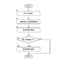
以下、登録領域の登録の前に測地変換部39による測地変換を行い、図4に示すような位置情報を取得可能な状態とした上での登録領域の登録について、図6のフローチャートに基づいて説明する。
まず、登録の対象となる圃場内において、作業車両であるトラクタ1を作業者の操縦により走行させる(ステップ#1)。このとき、圃場の角部を登録領域の基準地点としており、圃場内の端部側を周回走行させて、圃場の角部の夫々に対して、少なくともその近傍までトラクタ1を走行させるようにしている。
位置情報取得部32は、トラクタ1の位置情報を取得しており、トラクタ1を走行させたときのトラクタ1の走行軌跡を求め、基準地点の位置情報を取得している(ステップ#2)。例えば、図4では、圃場の角部を登録領域の基準地点Q1,Q2,Q3,Q4としており、トラクタ1の走行軌跡から、基準地点Q1,Q2,Q3,Q4の夫々における位置情報を取得している。
領域特定部34は、基準地点Q1,Q2,Q3,Q4の夫々における位置情報から、トラクタ1の走行領域を特定する(ステップ#3)。例えば、図4では、基準地点Q1,Q2,Q3,Q4を結ぶ線にて囲まれた領域を走行領域Qとして特定している。
ここで、特定した走行領域Qと取得している地図情報とを比較して、例えば、走行領域Qと道路K1,K2が隣接していない等、走行領域Qの位置情報と地図情報の位置情報とにずれが生じている場合(例えば、図3参照)には、再度、測地変換部39による測地変換を行うことが可能である。このように、再度の測地変換部39による測地変換を行うことで、より正確な位置情報を取得することができる。
判定部35は、領域特定部34にて特定された走行領域Qが禁止領域を含むか否かを判定し、登録部36は、走行領域Qが禁止領域を含まなければ、走行領域Qを登録領域として登録する(ステップ#4のNoの場合、ステップ#5)。また、登録部36は、走行領域Qが禁止領域を含むと、登録領域の登録を行わない(ステップ#4のYesの場合)。例えば、図4において、圃場の周囲に隣接する道路K1,K2が位置する領域を禁止領域Kとしており、走行領域Qがグレーの領域Q5のみを含む領域であると、走行領域Qが禁止領域Kを含まず、その走行領域Qを登録領域として登録する。一方、走行領域Qが、グレーの領域Q5に加えて、点線にて囲む領域Q6をも含む領域であると、走行領域Qが禁止領域Kを含むとして、登録領域の登録が行われない。ちなみに、登録領域の登録が行われない場合は、登録領域の再登録を行うように無線通信端末30のタッチパネル等に表示することができる。
上述の如く、走行領域Qに禁止領域Kが含まれている場合でも、禁止領域Kを含む領域を登録領域として登録しないことで、禁止領域Kにおけるトラクタ1の自律走行を阻止することができる。この実施形態では、禁止領域Kにおけるトラクタ1の自律走行を阻止するための対策として、禁止領域Kを含む領域を登録領域として登録しないという対策だけでなく、トラクタ1を自律走行させる場合にも、禁止領域Kにおけるトラクタ1の自律走行を防止するための対策を講じているので、その対策について説明する。
判定部35は、位置情報取得部32により取得されたトラクタ1の現在位置が登録領域内であるか否か、及び、地図情報においてトラクタ1の自律走行が禁止される禁止領域K内であるか否かを判定可能に構成されている。そして、図2に示すように、無線通信端末30には、判定部35によりトラクタ1の現在位置が登録領域内で且つ禁止領域K内であると判定された場合にトラクタ1の自律走行を禁止する自律走行禁止部38が備えられている。
以下、この自律走行時における対策について、図7のフローチャートに基づいて説明する。
トラクタ1を自律走行させる場合には、制御部23が、トラクタ1の現在位置を取得しているので、無線通信用アンテナ26と無線通信装置31との無線通信を介して、位置情報取得部32がトラクタ1の現在位置を取得している(ステップ#11)。判定部35は、取得したトラクタ1の現在位置が登録領域内であるか否か、及び、取得したトラクタ1の現在位置が禁止領域K内であるか否かを判定する(ステップ#12、ステップ#13)。
トラクタ1を自律走行させる場合には、制御部23が、トラクタ1の現在位置を取得しているので、無線通信用アンテナ26と無線通信装置31との無線通信を介して、位置情報取得部32がトラクタ1の現在位置を取得している(ステップ#11)。判定部35は、取得したトラクタ1の現在位置が登録領域内であるか否か、及び、取得したトラクタ1の現在位置が禁止領域K内であるか否かを判定する(ステップ#12、ステップ#13)。
自律走行禁止部38は、判定部35による判定により、トラクタ1の現在位置が登録領域T外であると(図8参照)、トラクタ1を走行停止させて自律走行を禁止する(ステップ#12のNoの場合、ステップ#14)。図8は、登録領域T内に禁止領域Kが存在する場合を示している。自律走行禁止部38は、判定部35による判定により、トラクタ1の現在位置が登録領域T内であっても禁止領域K内であると、トラクタ1を走行停止させて自律走行を禁止する(ステップ#12のYesの場合、ステップ#13のYesの場合、ステップ#14)。自律走行禁止部38によりトラクタ1の自律走行を禁止する場合には、自律走行禁止部38が、トラクタ1の自律走行を禁止するための指示信号を、無線通信装置31と無線通信用アンテナ26との間の無線通信を介して、トラクタ1の制御部23に送信する。制御部23は、自律走行禁止部38からの指示信号に基づいて、トラクタ1を走行停止させて自律走行を禁止すべく、ガバナ装置21や変速装置22等を制御する。このとき、無線通信端末30のタッチパネルやトラクタ1のモニタ部等に、自律走行を禁止したことにより走行停止した旨を表示することができる。
自律走行禁止部38は、判定部35による判定により、トラクタ1の現在位置が登録領域T内であり、且つ、トラクタ1の現在位置が禁止領域K外であると、トラクタ1の自律走行を継続させる(ステップ#12のYesの場合、ステップ#13のNoの場合、ステップ#15)。このとき、自律走行禁止部38から指示信号が送信されることは無く、トラクタ1の制御部23による自律走行が継続される。
このように、トラクタ1の現在位置が、登録領域Tから外れた場合だけでなく、登録領域T内であっても禁止領域K内であれば、トラクタ1の自律走行を禁止することができる。これにより、例えば、図8に示すように、登録領域T内に禁止領域Kが存在する場合でも、トラクタ1の現在位置が禁止領域K内になると、トラクタ1が走行停止されるので、禁止領域Kでの自律走行を阻止することができる。しかも、トラクタ1の現在位置を取得する度に判定部35による判定が行われるので、トラクタ1が禁止領域Kに侵入した早い段階でトラクタ1を走行停止させることができ、禁止領域Kでの自律走行をいち早く阻止できる。
この実施形態では、禁止領域Kにおけるトラクタ1の自律走行を阻止するための対策として、上述の2つの対策を講じているが、例えば、禁止領域Kを含む領域を登録領域として登録しないという対策だけを講じる、又は、トラクタ1の自律走行時にトラクタ1の現在位置が禁止領域K内となると自律走行を禁止するという対策のみを講じることも可能である。
〔別実施形態〕
(1)上記実施形態では、位置情報取得部32が基地局60の位置情報に基づいて世界測地系によりトラクタ1の位置情報を取得可能であるのに対して、地図情報は日本測地系による位置情報を含む地図情報であり、位置情報を取得する測地系が異なるが、トラクタ1の位置情報及び地図情報の両方を世界測地系又は日本測地系により同一の測地系により取得できる場合には、測地変換部39による測地変換を行わなくてもよい。この場合、測地変換部39による測地変換とは別に、地図自体の誤差や基地局60の位置情報の誤差を無くすための構成を備えることもできる。
(1)上記実施形態では、位置情報取得部32が基地局60の位置情報に基づいて世界測地系によりトラクタ1の位置情報を取得可能であるのに対して、地図情報は日本測地系による位置情報を含む地図情報であり、位置情報を取得する測地系が異なるが、トラクタ1の位置情報及び地図情報の両方を世界測地系又は日本測地系により同一の測地系により取得できる場合には、測地変換部39による測地変換を行わなくてもよい。この場合、測地変換部39による測地変換とは別に、地図自体の誤差や基地局60の位置情報の誤差を無くすための構成を備えることもできる。
(2)上記実施形態では、RTK測位によりトラクタ1の位置情報を取得するために、基地局60を設けているが、この基地局60に代えて、別の基地局64を備えることで、RTK測位によりトラクタ1の位置情報を取得することもできる。このように、別の基地局64を備える場合には、RTK測位に限らず、DGPS(ディファレンシャルGPS測位)等の各種の測位方法を適用することもできる。
(3)上記実施形態では、本発明に係る自律走行システムの位置情報取得部32や地図情報取得部33等を無線通信端末30に備えた場合を例示したが、本発明に係る自律走行システムの位置情報取得部32や地図情報取得部33等をどこに備えるかは適宜変更が可能である。例えば、本発明に係る自律走行システムの位置情報取得部32や地図情報取得部33等をトラクタ1の制御部23に備えることも可能であり、また、外部の制御装置等に本発明に係る自律走行システムの位置情報取得部32や地図情報取得部33等を備えることも可能である。
本発明は、予め登録された登録領域内において作業車両を自律走行させる各種の自律走行システムに適用できる。
1 トラクタ(作業車両)
32 位置情報取得部
33 地図情報取得部
34 領域特定部
35 判定部
36 登録部
38 自律走行禁止部
39 測地変換部
40 記憶部
41 モード実行部
42 補正部
60 基地局
64 別の基地局
32 位置情報取得部
33 地図情報取得部
34 領域特定部
35 判定部
36 登録部
38 自律走行禁止部
39 測地変換部
40 記憶部
41 モード実行部
42 補正部
60 基地局
64 別の基地局
Claims (6)
- 予め登録された登録領域内において作業車両を自律走行させる自律走行システムであって、
衛星測位システムにより特定される前記作業車両の位置情報を取得可能な位置情報取得部と、
地図情報を取得可能な地図情報取得部と、
前記作業車両の走行軌跡に基づいて走行領域を特定可能な領域特定部と、
前記領域特定部により特定された走行領域が前記地図情報において前記作業車両の自律走行が禁止される禁止領域を含むか否かを判定する判定部と、
前記判定部により前記走行領域に前記禁止領域が含まれないと判定される場合に前記走行領域を前記登録領域として登録する登録部と、を備えることを特徴とする自律走行システム。 - 予め登録された登録領域内において作業車両を自律走行させる自律走行システムであって、
衛星測位システムにより特定される前記作業車両の位置情報を取得可能な位置情報取得部と、
地図情報を取得可能な地図情報取得部と、
前記位置情報取得部により取得された前記作業車両の現在位置が前記登録領域内であるか否か、及び、前記地図情報において前記作業車両の自律走行が禁止される禁止領域内であるか否かを判定する判定部と、
前記判定部により前記作業車両の現在位置が前記登録領域内で且つ前記禁止領域内であると判定された場合に前記作業車両の自律走行を禁止する自律走行禁止部と、を備えることを特徴とする自律走行システム。 - 前記位置情報取得部は、基地局の位置情報に基づいてRTK測位により前記作業車両の位置情報を取得可能に構成されていることを特徴とする請求項1又は2に記載の自律走行システム。
- 前記位置情報取得部は所定の基地局の位置情報に基づいて世界測地系により前記作業車両の位置情報を取得可能であり、
前記地図情報は日本測地系による位置情報を含む地図情報であって、
世界測地系と日本測地系との補正値に基づいて前記所定の基地局の位置情報又は前記地図情報の位置情報の測地変換を行う測地変換部を備えることを特徴とする請求項1~3の何れか1項に記載の自律走行システム。 - 前記補正値を地域毎に対応付けて記憶する記憶部を備え、
前記測地変換部は、前記作業車両の現在位置が属する地域に対応付けられた前記補正値に基づいて前記測地変換を行うことを特徴とする請求項4に記載の自律走行システム。 - 前記測地変換部による前記測地変換における位置情報の誤差を補正する補正モードを実行可能なモード実行部を備え、
前記モード実行部により前記補正モードが実行されたときに単独測位又は前記所定の基地局とは別の基地局の位置情報に基づくRTK測位により前記所定の基地局の位置情報を補正する補正部を備えることを特徴とする請求項4又は5に記載の自律走行システム。
Applications Claiming Priority (2)
| Application Number | Priority Date | Filing Date | Title |
|---|---|---|---|
| JP2016105819A JP6694328B2 (ja) | 2016-05-27 | 2016-05-27 | 自律走行システム |
| JP2016-105819 | 2016-05-27 |
Publications (1)
| Publication Number | Publication Date |
|---|---|
| WO2017204052A1 true WO2017204052A1 (ja) | 2017-11-30 |
Family
ID=60411417
Family Applications (1)
| Application Number | Title | Priority Date | Filing Date |
|---|---|---|---|
| PCT/JP2017/018525 Ceased WO2017204052A1 (ja) | 2016-05-27 | 2017-05-17 | 自律走行システム |
Country Status (2)
| Country | Link |
|---|---|
| JP (1) | JP6694328B2 (ja) |
| WO (1) | WO2017204052A1 (ja) |
Cited By (3)
| Publication number | Priority date | Publication date | Assignee | Title |
|---|---|---|---|---|
| EP3506039A1 (en) * | 2017-12-27 | 2019-07-03 | Kubota Corporation | Work area determination system for autonomous traveling work machine, autonomous traveling work machine and work area determination program |
| JPWO2021240741A1 (ja) * | 2020-05-28 | 2021-12-02 | ||
| US20230168672A1 (en) * | 2021-11-30 | 2023-06-01 | Honda Motor Co., Ltd. | Travel route control of autonomous work vehichle using global navigation satellite system |
Families Citing this family (11)
| Publication number | Priority date | Publication date | Assignee | Title |
|---|---|---|---|---|
| JP6953304B2 (ja) * | 2017-12-28 | 2021-10-27 | 株式会社クボタ | 作業場管理システム |
| US10648820B2 (en) | 2018-01-03 | 2020-05-12 | Deere & Company | Methods and apparatus for assessing coordinate data |
| JP6953340B2 (ja) * | 2018-03-23 | 2021-10-27 | ヤンマーパワーテクノロジー株式会社 | 自動走行システム |
| JP6832884B2 (ja) * | 2018-03-29 | 2021-02-24 | ヤンマーパワーテクノロジー株式会社 | 自動走行システム及び状況報知装置 |
| JP6916491B6 (ja) * | 2018-05-24 | 2021-09-08 | イネーブラー株式会社 | 測位システム、基地局、および、測位方法 |
| JP2020174599A (ja) * | 2019-04-19 | 2020-10-29 | 株式会社Ihiアグリテック | Gisツールから作成したマップのキャリブレーションシステム |
| JP7037235B2 (ja) * | 2019-05-24 | 2022-03-16 | 株式会社ナイルワークス | 産業機械システム、産業機械、管制装置、産業機械システムの制御方法、および、産業機械システムの制御プログラム |
| JP7441393B2 (ja) * | 2020-06-29 | 2024-03-01 | 井関農機株式会社 | 作業車両の制御システム |
| KR102660840B1 (ko) * | 2021-10-05 | 2024-04-25 | 주식회사 엘지유플러스 | Mec 서버를 이용한, 클라우드 기반 자율 주행 서비스 제공 방법 및 이를 위한 시스템 |
| JP7720034B2 (ja) * | 2023-01-31 | 2025-08-07 | 井関農機株式会社 | 作業車両 |
| JP7599603B1 (ja) * | 2024-05-24 | 2024-12-13 | 株式会社Ihiアグリテック | 農作業用自動化システム及び当該システムを搭載した農業機械 |
Citations (6)
| Publication number | Priority date | Publication date | Assignee | Title |
|---|---|---|---|---|
| JPS62140080A (ja) * | 1985-12-16 | 1987-06-23 | Mazda Motor Corp | 車両用走行誘導装置 |
| JPH09178481A (ja) * | 1995-12-25 | 1997-07-11 | Kubota Corp | 作業車の走行用データ作成装置及び誘導制御装置 |
| JP2002354905A (ja) * | 2001-05-31 | 2002-12-10 | Yanmar Agricult Equip Co Ltd | 農業用作業車 |
| JP2003269966A (ja) * | 2002-03-19 | 2003-09-25 | Sanyo Electric Co Ltd | 車 両 |
| JP2015075423A (ja) * | 2013-10-10 | 2015-04-20 | 株式会社デンソー | 地図データ書き換え装置および地図データ書き換えプログラム |
| WO2015119266A1 (ja) * | 2014-02-06 | 2015-08-13 | ヤンマー株式会社 | 併走作業システム |
Family Cites Families (3)
| Publication number | Priority date | Publication date | Assignee | Title |
|---|---|---|---|---|
| US8116977B2 (en) * | 2008-10-02 | 2012-02-14 | Trimble Navigation Limited | Automatic control of passive, towed implements |
| JP2014154047A (ja) * | 2013-02-12 | 2014-08-25 | Tsubakimoto Chain Co | 指示装置及びプログラム |
| JP6004977B2 (ja) * | 2013-03-22 | 2016-10-12 | 株式会社クボタ | 作業車 |
-
2016
- 2016-05-27 JP JP2016105819A patent/JP6694328B2/ja active Active
-
2017
- 2017-05-17 WO PCT/JP2017/018525 patent/WO2017204052A1/ja not_active Ceased
Patent Citations (6)
| Publication number | Priority date | Publication date | Assignee | Title |
|---|---|---|---|---|
| JPS62140080A (ja) * | 1985-12-16 | 1987-06-23 | Mazda Motor Corp | 車両用走行誘導装置 |
| JPH09178481A (ja) * | 1995-12-25 | 1997-07-11 | Kubota Corp | 作業車の走行用データ作成装置及び誘導制御装置 |
| JP2002354905A (ja) * | 2001-05-31 | 2002-12-10 | Yanmar Agricult Equip Co Ltd | 農業用作業車 |
| JP2003269966A (ja) * | 2002-03-19 | 2003-09-25 | Sanyo Electric Co Ltd | 車 両 |
| JP2015075423A (ja) * | 2013-10-10 | 2015-04-20 | 株式会社デンソー | 地図データ書き換え装置および地図データ書き換えプログラム |
| WO2015119266A1 (ja) * | 2014-02-06 | 2015-08-13 | ヤンマー株式会社 | 併走作業システム |
Non-Patent Citations (1)
| Title |
|---|
| MIKIO TOBITA: "Kokai no Anzen to Shoene Uchu Sokuchi ni yoru Chikyujo no Ichi no Hakarikatao Arawashikata", JOURNAL OF THE SOCIETY OF INSTRUMENT AND CONTROL ENGINEERS, vol. 50, no. 6, June 2011 (2011-06-01), pages 374 - 379 * |
Cited By (9)
| Publication number | Priority date | Publication date | Assignee | Title |
|---|---|---|---|---|
| EP3506039A1 (en) * | 2017-12-27 | 2019-07-03 | Kubota Corporation | Work area determination system for autonomous traveling work machine, autonomous traveling work machine and work area determination program |
| US11119495B2 (en) | 2017-12-27 | 2021-09-14 | Kubota Corporation | Work area determination system for autonomous traveling work machine, autonomous traveling work machine and work area determination program |
| JPWO2021240741A1 (ja) * | 2020-05-28 | 2021-12-02 | ||
| WO2021240741A1 (ja) * | 2020-05-28 | 2021-12-02 | カワサキモータース株式会社 | ユーティリティビークル |
| CN115552498A (zh) * | 2020-05-28 | 2022-12-30 | 川崎摩托株式会社 | 多用途车 |
| JP7514306B2 (ja) | 2020-05-28 | 2024-07-10 | カワサキモータース株式会社 | ユーティリティビークル |
| US12246738B2 (en) | 2020-05-28 | 2025-03-11 | Kawasaki Motors, Ltd. | Autonomous and manual mode swtiching for utility vehicle |
| US20230168672A1 (en) * | 2021-11-30 | 2023-06-01 | Honda Motor Co., Ltd. | Travel route control of autonomous work vehichle using global navigation satellite system |
| US12510891B2 (en) * | 2021-11-30 | 2025-12-30 | Honda Motor Co., Ltd. | Travel route control of autonomous work vehicle to reduce travel distance |
Also Published As
| Publication number | Publication date |
|---|---|
| JP2017211892A (ja) | 2017-11-30 |
| JP6694328B2 (ja) | 2020-05-13 |
Similar Documents
| Publication | Publication Date | Title |
|---|---|---|
| JP6694328B2 (ja) | 自律走行システム | |
| US10813267B2 (en) | Control apparatus for automatic traveling vehicle | |
| EP3176665B1 (en) | Cooperation system for work vehicles | |
| US9448561B2 (en) | Work vehicle cooperation system | |
| EP3351077B1 (en) | Travel route generation device and travel route generation program | |
| JP7779966B2 (ja) | トラクタ | |
| KR102534336B1 (ko) | 경로 생성 시스템 | |
| US20190227561A1 (en) | Work vehicle and travel region specifying device | |
| JP7282660B2 (ja) | 作業機 | |
| JP2017187394A (ja) | 測位検出装置及び測位検出装置を備えた作業機 | |
| WO2020129704A1 (ja) | 走行作業機 | |
| JP2025157490A (ja) | 作業車両支援システム及び作業車両支援方法 | |
| JP7083001B2 (ja) | 自律走行システム | |
| WO2021106389A1 (ja) | 自律走行制御システム | |
| JP2017161987A (ja) | 作業車両の走行領域形状登録システム | |
| CN114859915A (zh) | 行驶区域形状登记系统 | |
| WO2020129722A1 (ja) | 自動走行作業車のための制御装置 | |
| JP2019133701A (ja) | 走行領域形状登録システム | |
| JP6879896B2 (ja) | 作業車のための衛星測位システム | |
| JP2019096363A (ja) | 走行領域特定装置 | |
| CN114302640A (zh) | 区域登记系统 | |
| JP6945353B2 (ja) | 自動走行作業車 | |
| JP7223087B2 (ja) | 走行経路特定方法 | |
| JP2020099227A (ja) | 走行作業機 | |
| JP7398328B2 (ja) | 作業車両 |
Legal Events
| Date | Code | Title | Description |
|---|---|---|---|
| 121 | Ep: the epo has been informed by wipo that ep was designated in this application |
Ref document number: 17802644 Country of ref document: EP Kind code of ref document: A1 |
|
| NENP | Non-entry into the national phase |
Ref country code: DE |
|
| 122 | Ep: pct application non-entry in european phase |
Ref document number: 17802644 Country of ref document: EP Kind code of ref document: A1 |