EP3351077B1 - Travel route generation device and travel route generation program - Google Patents
Travel route generation device and travel route generation program Download PDFInfo
- Publication number
- EP3351077B1 EP3351077B1 EP17001059.9A EP17001059A EP3351077B1 EP 3351077 B1 EP3351077 B1 EP 3351077B1 EP 17001059 A EP17001059 A EP 17001059A EP 3351077 B1 EP3351077 B1 EP 3351077B1
- Authority
- EP
- European Patent Office
- Prior art keywords
- point
- work
- travel route
- shape
- entrance passage
- Prior art date
- Legal status (The legal status is an assumption and is not a legal conclusion. Google has not performed a legal analysis and makes no representation as to the accuracy of the status listed.)
- Active
Links
- 238000004364 calculation method Methods 0.000 claims description 28
- 238000000034 method Methods 0.000 claims description 20
- 238000004590 computer program Methods 0.000 claims description 13
- 230000006870 function Effects 0.000 description 27
- 238000012545 processing Methods 0.000 description 10
- 238000004891 communication Methods 0.000 description 8
- 238000001514 detection method Methods 0.000 description 7
- 230000000694 effects Effects 0.000 description 4
- 238000007726 management method Methods 0.000 description 4
- 238000013459 approach Methods 0.000 description 3
- 230000005540 biological transmission Effects 0.000 description 2
- 238000010586 diagram Methods 0.000 description 2
- 240000007594 Oryza sativa Species 0.000 description 1
- 235000007164 Oryza sativa Nutrition 0.000 description 1
- 230000001133 acceleration Effects 0.000 description 1
- 238000004422 calculation algorithm Methods 0.000 description 1
- 239000000969 carrier Substances 0.000 description 1
- 230000001413 cellular effect Effects 0.000 description 1
- 238000007405 data analysis Methods 0.000 description 1
- 230000001419 dependent effect Effects 0.000 description 1
- 230000007717 exclusion Effects 0.000 description 1
- 239000003337 fertilizer Substances 0.000 description 1
- 238000005259 measurement Methods 0.000 description 1
- 238000005192 partition Methods 0.000 description 1
- 235000009566 rice Nutrition 0.000 description 1
- 239000004065 semiconductor Substances 0.000 description 1
- 230000000007 visual effect Effects 0.000 description 1
Images


Classifications
-
- A—HUMAN NECESSITIES
- A01—AGRICULTURE; FORESTRY; ANIMAL HUSBANDRY; HUNTING; TRAPPING; FISHING
- A01B—SOIL WORKING IN AGRICULTURE OR FORESTRY; PARTS, DETAILS, OR ACCESSORIES OF AGRICULTURAL MACHINES OR IMPLEMENTS, IN GENERAL
- A01B69/00—Steering of agricultural machines or implements; Guiding agricultural machines or implements on a desired track
-
- G—PHYSICS
- G05—CONTROLLING; REGULATING
- G05D—SYSTEMS FOR CONTROLLING OR REGULATING NON-ELECTRIC VARIABLES
- G05D1/00—Control of position, course or altitude of land, water, air, or space vehicles, e.g. automatic pilot
- G05D1/02—Control of position or course in two dimensions
- G05D1/021—Control of position or course in two dimensions specially adapted to land vehicles
- G05D1/0259—Control of position or course in two dimensions specially adapted to land vehicles using magnetic or electromagnetic means
-
- A—HUMAN NECESSITIES
- A01—AGRICULTURE; FORESTRY; ANIMAL HUSBANDRY; HUNTING; TRAPPING; FISHING
- A01B—SOIL WORKING IN AGRICULTURE OR FORESTRY; PARTS, DETAILS, OR ACCESSORIES OF AGRICULTURAL MACHINES OR IMPLEMENTS, IN GENERAL
- A01B69/00—Steering of agricultural machines or implements; Guiding agricultural machines or implements on a desired track
- A01B69/007—Steering or guiding of agricultural vehicles, e.g. steering of the tractor to keep the plough in the furrow
- A01B69/008—Steering or guiding of agricultural vehicles, e.g. steering of the tractor to keep the plough in the furrow automatic
-
- G—PHYSICS
- G05—CONTROLLING; REGULATING
- G05D—SYSTEMS FOR CONTROLLING OR REGULATING NON-ELECTRIC VARIABLES
- G05D1/00—Control of position, course or altitude of land, water, air, or space vehicles, e.g. automatic pilot
- G05D1/02—Control of position or course in two dimensions
- G05D1/021—Control of position or course in two dimensions specially adapted to land vehicles
- G05D1/0276—Control of position or course in two dimensions specially adapted to land vehicles using signals provided by a source external to the vehicle
- G05D1/0278—Control of position or course in two dimensions specially adapted to land vehicles using signals provided by a source external to the vehicle using satellite positioning signals, e.g. GPS
-
- G—PHYSICS
- G05—CONTROLLING; REGULATING
- G05D—SYSTEMS FOR CONTROLLING OR REGULATING NON-ELECTRIC VARIABLES
- G05D1/00—Control of position, course or altitude of land, water, air, or space vehicles, e.g. automatic pilot
- G05D1/02—Control of position or course in two dimensions
- G05D1/021—Control of position or course in two dimensions specially adapted to land vehicles
- G05D1/0276—Control of position or course in two dimensions specially adapted to land vehicles using signals provided by a source external to the vehicle
- G05D1/0285—Control of position or course in two dimensions specially adapted to land vehicles using signals provided by a source external to the vehicle using signals transmitted via a public communication network, e.g. GSM network
-
- A—HUMAN NECESSITIES
- A01—AGRICULTURE; FORESTRY; ANIMAL HUSBANDRY; HUNTING; TRAPPING; FISHING
- A01B—SOIL WORKING IN AGRICULTURE OR FORESTRY; PARTS, DETAILS, OR ACCESSORIES OF AGRICULTURAL MACHINES OR IMPLEMENTS, IN GENERAL
- A01B79/00—Methods for working soil
- A01B79/005—Precision agriculture
-
- Y—GENERAL TAGGING OF NEW TECHNOLOGICAL DEVELOPMENTS; GENERAL TAGGING OF CROSS-SECTIONAL TECHNOLOGIES SPANNING OVER SEVERAL SECTIONS OF THE IPC; TECHNICAL SUBJECTS COVERED BY FORMER USPC CROSS-REFERENCE ART COLLECTIONS [XRACs] AND DIGESTS
- Y02—TECHNOLOGIES OR APPLICATIONS FOR MITIGATION OR ADAPTATION AGAINST CLIMATE CHANGE
- Y02A—TECHNOLOGIES FOR ADAPTATION TO CLIMATE CHANGE
- Y02A40/00—Adaptation technologies in agriculture, forestry, livestock or agroalimentary production
- Y02A40/10—Adaptation technologies in agriculture, forestry, livestock or agroalimentary production in agriculture
- Y02A40/22—Improving land use; Improving water use or availability; Controlling erosion
Description
- The present invention relates to a travel route generation device and a travel route generation program that generate a travel route for a work vehicle that automatically travels in a work field.
- In recent years, a work vehicle that works while automatically traveling in a work field has been proposed. In order to cause a work vehicle to travel automatically in this way, it is necessary to generate a travel route that serves as a travel target. In order to generate a travel route that covers a work field, it is a precondition to accurately grasp a shape of the work field. Since a work field such as a field is divided by a private farm road or the like, it is difficult to determine an accurate shape of the work field from a general map.
- Therefore,
JP 2016-31649 A - (1) A driver gets into a tractor and enters a field by a manual operation.
- (2) Start a teaching program for the tractor.
- (3) Move the tractor to a nearby corner of the field, move the tractor to a starting point of headland tilling, and take down a tilling machine. Through an operation of lifting down the tilling machine, a work field shape calculating module regards a point of lifting down the tilling machine as a corner point of the field external shape.
- (4) Lift up the tilling machine once and proceed to a next corner while imagining tilling work.
- (5) Move a child tractor to the tilling work travel starting point after turning travel, and lift down the tilling machine. Repeat this work and input each corner point of the field external shape.
- (6) The work field shape is calculated by making the corner points of the field external shape, a field entrance, and an entrance direction as input parameters.
- The travel route for the tractor to automatically travel in a central work field positioned inside a headland is generated using the work field shape calculated in this way.
-
US 2016/174453 A1 discloses a work vehicle coordinating system including a main vehicle position detection module for detecting a position of a main work vehicle, a sub vehicle position detection module for detecting a position of a sub work vehicle, a central work land path calculation section for calculating a central work land traveling path to be used by the sub work vehicle in an unmanned steered work traveling in a central work land, a first steering control section for unmanned-steering the sub work vehicle ahead of the main work vehicle based on the position of the sub work vehicle detected by the sub vehicle position detection module and the central work land traveling path, a headland path calculation section for calculating a headland traveling path and a second steering control section for unmanned-steering the sub work vehicle. -
US 2007/192024 A1 discloses a path planer and method for planning a path of a vehicle defining a reference row having a reference contour in a work area. A representation of the defined reference row is established. -
EP 3 042 554 A1 discloses a route setting device of an agricultural working vehicle. -
WO 2012/142395 A1 discloses a system for providing visual crop data to a mobile device including at least one server computer in communication with a mobile device. -
WO 2017/004074 A1 discloses systems and methods for capturing images of a field and performing agricultural data analysis of the images. -
US 2004/193349 A1 discloses a system and method for determining a path plan for a vehicle including organizing a work area into partition areas based on at least one of an obstacle, a concavity, and an exclusion area associated with a work area. - A work field such as a field may be divided by a boundary, such as a ridge, and an entrance passage for the work vehicle to enter and leave the work field may be determined for each work field. This entrance passage may be an inclined passage or a firmly hardened passage, and thus may be a region in which the work vehicle does not perform work. However, in calculation of the work field shape through the teaching travel in
JP 2016-31649 A - The present invention is defined by
independent claims - According to an aspect, a travel route generation device is provided. The travel route generation device may be for a work vehicle that enters and leaves a work field divided by a boundary through an entrance passage. The travel route generation device may include: a starting point registration unit that is configured to position-register a first endpoint on a side of the boundary of the entrance passage as a starting point; an intermediate point registration unit that is configured to position-register a shape feature point that prescribes a shape of the work field as an intermediate point; an end point registration unit that is configured to position-register a second endpoint facing the first endpoint on a side of the boundary of the entrance passage as an end point; a basic shape calculation unit that is configured to calculate a basic shape of the work field by connecting a position of the starting point, a position of the intermediate point, and a position of the end point; an entrance passage information generation unit that is configured to generate entrance passage information with a quadrangle as a shape of the entrance passage, the quadrangle having the starting point and the end point as opposite vertices and having two sides along an external shape extension line of the basic shape; and a travel route generation unit that is configured to define a region other than the entrance passage of the work field as a target work region, and to generate a travel route for the work vehicle to automatically travel in the target work region.
- Note that terms indicating geometrical shapes used in the present disclosure, for example, a triangle, a quadrangle, a rectangle, and a polygon, are not used in order to identify a geometrically strict shape, but are used in order to describe such a shape that can generally be seen or understood as being almost a corresponding geometrical shape as a whole. Therefore, each side of a polygon is not always a straight line and may be (slightly) bended and/or uneven.
- Further, in various embodiments and examples as described herein, the term "position-register" may be understood as to identify and/or register a position of a point. To "register" a position of a point, the travel route generation device may, for example, store information indicating the position of the point in a storage device.
- This configuration may allow calculation of the basic shape of the work field by connecting the position of the starting point, the position of the intermediate point, and the position of the end point acquired in movement along the boundary of the work field that leaves one end of the entrance passage and returns to the other end of the entrance passage. The work field may be regarded as a polygon and the intermediate point may correspond to a polygon vertex, which may be a feature point of the shape. When the work field is a triangle, the number of intermediate points is one, when the work field is a quadrangle, the number of intermediate points is two, and when the work field is a pentagon, the number of intermediate points is three. The entrance passage can be regarded as a quadrangle that is substantially a rectangle. Since the starting point and the end point may correspond to opposite vertices of the rectangle, the shape of the rectangle indicating the entrance passage can be calculated. Accordingly, the basic shape of the work field may be a polygon in which a small rectangle (e.g. quadrangle) is interposed at a place corresponding to the entrance passage. Therefore, the target work region in which the work vehicle needs to work may be obtained by removing the rectangle indicating the entrance passage from the calculated work field shape. The travel route generation unit may generate the travel route that covers this target work region, thereby providing the travel route that causes neither problem that the travel route and the entrance passage overlap each other nor problem that the travel route is distant from the entrance passage.
- Since the entrance passage may be inclined in the work field such as a field, it may be important that travel of the work vehicle that enters the target work region from the entrance passage is straight movement and that travel of the work vehicle immediately before leaving the target work region for the entrance passage is straight movement. Accordingly, it may be important to consider a travel direction of the work vehicle in the entrance passage as one of conditions of travel route generation. Therefore, it may be advantageous when the travel direction in the entrance passage is also calculated in addition to the shape of the entrance passage. For this object, in some examples, the entrance passage information generation unit may be configured to define vertices other than the starting point and the end point of the quadrangle representing the shape of the entrance passage as an inner point that is adjacent to the target work region and an outer point distant from the target work region, and a direction from a side connecting the outer point and the end point to a side connecting the starting point and the inner point may be an entry direction of the work vehicle into the target work region.
- When it is assumed that the shape of the entrance passage is a quadrangle, the inner point and the outer point can be calculated from the positions of the starting point and the end point, which may be opposite vertices of the quadrangle. Since the position of the inner point may determine a boundary of the entrance passage and the target work region, it is preferable to detect as actual position as possible. Therefore, in some examples, an inner point registration unit may be provided that is configured to define vertices other than the starting point and the end point of the quadrangle representing the shape of the entrance passage as an inner point that is adjacent to the target work region and an outer point distant from the target work region, and to register the inner point. Employing the inner point registered as an actual position may allow more accurate calculation of the shape of the entrance passage.
- Position coordinates needed for position-registration of the starting point, the intermediate point, and the end point may be a work field coordinate system or a latitude longitude system. However, a satellite positioning module may be mounted on the work vehicle that travels automatically, and it may be advantageous to use this satellite positioning module. Therefore, in some examples, position-registration of the starting point, the intermediate point, and the end point may be performed through traveling of the work vehicle along the boundary, and the positions of the starting point, the intermediate point, and the end point may be calculated using an own position based on positioning data from a satellite positioning module mounted on the work vehicle. With this configuration, since the work vehicle itself is used as a position measuring instrument, movement for work field shape measurement may be easy even if the work field is vast. A position detecting system using the satellite positioning module mounted on the work vehicle may be used, which may be advantageous in terms of cost as well.
- When the work vehicle itself is used as a position measuring instrument, even when the work vehicle approaches the shape feature point of the work field (e.g. a vertex of a polygon), there may be a distance between the own position that is typically set for automatic travel and the position of the shape feature point. In order to solve a positional error caused by this distance, in some examples, the travel route generation device may be configured such that one or more aiming points associated with the positions of the starting point, the intermediate point, and the end point are prescribed at corners of the work vehicle, and the positions of the starting point, the intermediate point, and the end point are calculated by modifying the own position according to distances from the own position to the aiming points. This may enable the work vehicle to measure the positions accurately only by causing an appropriate corner (e.g. aiming point) of the work vehicle to approach the shape feature point of the work field. Preferably, setting such aiming points at a front right end, front left end, rear right end, and rear left end of the work vehicle and selecting one of the four ends may allow the aiming point to smoothly match the shape feature point of the work field. In some examples, one of the aiming points may be selected by a user and the selected aiming point may be used for calculating a position of one or more of: the starting point, the intermediate point, the end point.
- According to another aspect, a travel route generation device is provided, the travel route generation device being configured to calculate a shape of an arbitrary region in the work field as the target work region and generate the travel route independently of the entrance. Such a travel route generation device for a work vehicle may include: a starting point registration unit that is configured to position-register a first endpoint of a target work region for work travel as a starting point; an intermediate point registration unit that is configured to position-register a shape feature point that prescribes a shape of the target work region as an intermediate point; an end point registration unit that is configured to position-register the first endpoint or a second endpoint adjacent to the first endpoint as an end point; a basic shape calculation unit that is configured to calculate a basic shape of the target work region by connecting a position of the starting point, a position of the intermediate point, and a position of the end point; and a travel route generation unit that is configured to generate a travel route for the work vehicle to automatically travel in the target work region, wherein one or more aiming points associated with the positions of the starting point, the intermediate point, and the end point may be prescribed at corners of the work vehicle or a vehicle capable of traveling in the target work region, and the positions of the starting point, the intermediate point, and the end point may be calculated by modifying an own position according to distances from the own position to the aiming points. This travel route generation device, which may use the work vehicle or a vehicle capable of traveling in the target work region as a position measuring instrument, can calculate the shape smoothly even if the target work region is vast. In some examples of this aspect, one of the aiming points may be selected by a user and the selected aiming point may be used for calculating a position of one or more of: the starting point, the intermediate point, the end point.
- Functions of the travel route generation device described above can be substantially implemented by execution of a computer program installed in a computer. Therefore, the present disclosure also provides such a computer program. For example, according to an aspect, a computer program product for travel route generation is provided for a work vehicle that enters and leaves a work field divided by a boundary through an entrance passage. The computer program product may cause a computer to execute: a starting point registration function of position-registering a first endpoint on a side of the boundary of the entrance passage as a starting point; an intermediate point registration function of position-registering a shape feature point that prescribes a shape of the work field as an intermediate point; an end point registration function of position-registering a second endpoint facing the first endpoint on a side of the boundary of the entrance passage as an end point; a basic shape calculation function of calculating a basic shape of the work field by connecting a position of the starting point, a position of the intermediate point, and a position of the end point; an entrance passage information generation function of generating entrance passage information with a quadrangle as a shape of the entrance passage, the quadrangle having the starting point and the end point as opposite vertices and having two sides along an external shape extension line of the basic shape; and a travel route generation function of defining a region other than the entrance passage of the work field as a target work region, and generating a travel route for the work vehicle to automatically travel in the target work region. Functions and effects of this travel route generation program may be identical to functions and effects of the above-described travel route generation device. In addition, the above-described examples of the travel route generation device may also be applicable to this travel route generation program.
- In various embodiments and examples described herein, a "function" of a computer program product may be understood as indicating a group of computer-readable instructions that, when loaded and run on a computer, cause the computer to execute one or more process steps defined by the instructions. Accordingly, in various embodiments and examples described herein, the term "function" is not limited to a function, module, class, method or the like of any specific programming language.
- Similarly, the present disclosure may also be applied to a computer program product for travel route generation, which may cause a computer to calculate a shape of an arbitrary region in the work field as a target work region and generates a travel route independently of the entrance. This computer program product for travel route generation for a work vehicle may cause a computer to execute: a starting point registration function of position-registering a first endpoint of a target work region for work travel as a starting point; an intermediate point registration function of position-registering a shape feature point that prescribes a shape of the target work region as an intermediate point; an end point registration function of position-registering the first endpoint or a second endpoint adjacent to the first endpoint as an end point; a basic shape calculation function of calculating a basic shape of the target work region by connecting a position of the starting point, a position of the intermediate point, and a position of the end point; a travel route generation function of generating a travel route for the work vehicle to automatically travel in the target work region; and a function of calculating the positions of the starting point, the intermediate point, and the end point, by modifying an own position according to distances from the own position to one or more aiming points associated with the positions of the starting point, the intermediate point, and the end point, the aiming points being prescribed at corners of the work vehicle or a vehicle capable of traveling in the target work region. Functions and effects of this computer program product for travel route generation may also be identical to the functions and effects of the above-described travel route generation device. In addition, the above-described examples of the travel route generation device may also be applicable to this computer program product for travel route generation.
- According to yet another aspect, a computer implemented method is provided for travel route generation for a work vehicle that enters and leaves a work field divided by a boundary through an entrance passage. The method may comprise the following:
- position-registering a first endpoint on a side of the boundary of the entrance passage as a starting point;
- position-registering a shape feature point that prescribes a shape of the work field as an intermediate point;
- position-registering a second endpoint facing the first endpoint on a side of the boundary of the entrance passage as an end point;
- calculating a basic shape of the work field by connecting a position of the starting point, a position of the intermediate point, and a position of the end point;
- generating entrance passage information with a quadrangle as a shape of the entrance passage, the quadrangle having the starting point and the end point as opposite vertices and having two sides along an external shape extension line of the basic shape; and
- defining a region other than the entrance passage of the work field as a target work region, and generating a travel route for the work vehicle to automatically travel in the target work region.
- According to yet another aspect, a computer-implemented method for travel route generation for a work vehicle is provided. The method may comprise the following:
- position-registering a first endpoint of a target work region for work travel as a starting point;
- position-registering a shape feature point that prescribes a shape of the target work region as an intermediate point;
- position-registering one of the first endpoint and a second endpoint adjacent to the first endpoint as an end point;
- calculating a basic shape of the target work region by connecting a position of the starting point, a position of the intermediate point, and a position of the end point;
- generating a travel route for the work vehicle to automatically travel in the target work region; and
- calculating the positions of the starting point, the intermediate point, and the end point, by modifying an own position according to distances from the own position to one or more aiming points associated with the positions of the starting point, the intermediate point, and the end point, the aiming points being prescribed at corners of one of the work vehicle and a vehicle capable of traveling in the target work region.
- The subject matter described in the application can be implemented as a method or as a system, possibly in the form of one or more computer program products. The subject matter described in the application can be implemented in a data signal or on a machine readable medium, where the medium is embodied in one or more information carriers, such as a CD-ROM, a DVD-ROM, a semiconductor memory, or a hard disk. Such computer program products may cause a data processing apparatus to perform one or more operations described in the application.
- In addition, subject matter described in the application can also be implemented as a system including a processor, and a memory coupled to the processor. The memory may encode one or more programs to cause the processor to perform one or more of the methods described in the application. Further subject matter described in the application can be implemented using various machines.
- Details of one or more implementations are set forth in the exemplary drawings and description below. Other features will be apparent from the description, the drawings, and from the claims. It should be understood, however, that even though embodiments are separately described, single features of different embodiments may be combined to further embodiments.
-
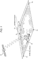
Fig. 1 is a schematic view illustrating how a work vehicle may enter a work field divided by a ridge through an entrance passage and measure a shape of the work field. -
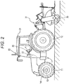
Fig. 2 is a side view of a tractor, which is one example of the work vehicle. -
Fig. 3 is a functional block diagram illustrating exemplary control function units that function as a travel route generation device. -
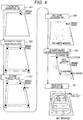
Fig. 4 is a flowchart illustrating an exemplary process of calculating shapes of the work field and the entrance passage in the travel route generation device. -
Fig. 5 is a schematic view illustrating an exemplary relationship between aiming points set in the tractor and aiming point selection buttons displayed on a touch panel. - One exemplary embodiment of a work vehicle equipped with a travel route generation device according to the present invention will be described with reference to the drawings. In this exemplary embodiment, the work vehicle is a tractor equipped with a
work device 30 in avehicle body 1. To begin with, the tractor may be operated by a user to perform teaching travel for calculating a field shape. In this teaching travel, the tractor may enter a field through an entrance passage inclined downward from a farm road, and perform circumferential travel along a boundary of the field divided by a ridge. At that time, as will be described in detail later, a first endpoint on a ridge side of the entrance passage may be position-registered as a starting point Ps, shape feature points that prescribe the field shape may be position-registered as intermediate points P1, P2, and P3, and a second endpoint facing the first endpoint on the ridge side of the entrance passage may be position-registered as an end point Pe. A basic shape of the field may be calculated by a line that connects the starting point Ps, the intermediate points P1, P2, and P3, and the end point Pe. A region obtained by excluding the entrance passage from this basic shape of the field may be referred to as a target work region. Furthermore, a shape of the entrance passage may be regarded as a quadrangle, a vertex that is adjacent to the target work region in vertices other than the starting point Ps and the end point Pe may be defined as an inner point Pa, and a vertex distant from the target work region may be defined as an outer point Pb. - As illustrated in
Fig. 2 , this exemplary tractor may be provided with acab 20 in a central portion of thevehicle body 1 supported byfront wheels 11 andrear wheels 12. The tractor may be equipped with thework device 30, which in this example is a rotary tilling machine, via ahydraulic lifting mechanism 31 at a rear of thevehicle body 1. Thefront wheels 11 may function as steering control wheels through which the tractor changes a travel direction when a steering angle of the steering control wheels is changed. The steering angle of thefront wheels 11 may be changed by an operation of asteering mechanism 13. Thesteering mechanism 13 may include asteering motor 14 for automatic steering. For manual traveling, thefront wheels 11 can be steered by operating asteering wheel 22 disposed in thecab 20. Thecab 20 may be equipped with ageneral purpose terminal 4 that may provide a user with information and receive instructions from the user. Thegeneral purpose terminal 4 may be implemented by one or more processors and one or more storage devices, such as a memory, coupled to the one or more processors. In acabin 21 of the tractor, asatellite positioning module 80 may be provided. As a component of thesatellite positioning module 80, a satellite antenna for receiving a global navigation satellite system (GNSS) signal (including a GPS signal) may be attached at a ceiling area of thecabin 21. Note that thesatellite positioning module 80 may be combined with an inertial navigation module incorporated with a gyro acceleration sensor and/or a magnetic director sensor for complementing satellite navigation. As a matter of course, the inertial navigation module may be provided in a different location from the location of thesatellite positioning module 80. -
Fig. 3 illustrates an exemplary control system configured in this tractor. The control system of this exemplary embodiment may include a first control unit, which may be thegeneral purpose terminal 4 including a graphical user interface, a controllingunit 5 that may control thevehicle body 1 and thework device 30 of the tractor, and/or aremote controller 84 for wirelessly controlling travel start and travel stop of the tractor from outside. The travel route generation device according to the present invention may be modularized as aroute generation module 6, and be incorporated into thegeneral purpose terminal 4. - In addition to the
route generation module 6, thegeneral purpose terminal 4 may have functions of a general computer system, such as acommunication control unit 40, atouch panel 60, and an input/output management unit 61 that manages an input operation on thetouch panel 60 and/or information display on thetouch panel 60. Thegeneral purpose terminal 4 may be coupled to the controllingunit 5 in such a manner that thegeneral purpose terminal 4 can exchange data by vehicle-mounted LAN, wireless communication, cable communication, or the like. Furthermore, thegeneral purpose terminal 4 can exchange data with acontrol computer 100 configured in a remote control center KS via a wireless channel or the Internet. In addition, it is also possible to carry thegeneral purpose terminal 4 out of the tractor for use if thegeneral purpose terminal 4 is configured as a device such as a tablet computer and a cellular phone and is data-exchangably coupled to the control system of the tractor. - In this exemplary embodiment, field information including a position of the field on a map and arrangement of farm roads surrounding the field may be stored in a field
information storage unit 101 of thecontrol computer 100, and this field information may be needed for finding out the field to work. Thecontrol computer 100 may also include a workplan management unit 102 that manages a work plan describing the work in a specified field. Thegeneral purpose terminal 4 can access thecontrol computer 100, and download the field information from the fieldinformation storage unit 101 and the work plan from the workplan management unit 102. Alternatively, thegeneral purpose terminal 4 can also input the field information and the work plan via a recording medium such as a USB memory. - The
route generation module 6 may include a work fieldshape calculation submodule 62 that calculates a shape of the target work region, which is a valid work region of the field, through the teaching travel, and/or a travelroute generation unit 63 that generates a travel route for the tractor to travel in the target work region. The work fieldshape calculation submodule 62 may include a startingpoint registration unit 621, an intermediatepoint registration unit 622, an endpoint registration unit 623, a basicshape calculation unit 624, an entrance passageinformation generation unit 625, and/or ashape editing unit 626. Furthermore, an innerpoint registration unit 627 may also be prepared as an option. - Next, a basic role of each functional unit of the
route generation module 6 will be described with reference to a flowchart of an exemplary field shape calculation process and a travel route generation process illustrated inFig. 4 . In the example shown inFig. 4 , the field shape is a trapezoid, and an entrance passage inclined downward is provided at a right end of an upper side. Furthermore, as illustrated inFig. 5 , aiming points T1, T2, T3, and T4 may be prescribed at four corners of the tractor. Distances between these aiming points T1, T2, T3, and T4 and the own position based on positioning data from the satellite positioning module 80 (illustrated with a black dot at the center of the vehicle body inFig. 5 ) may be set in advance. Position coordinates of the aiming points T1, T2, T3, and T4 can be calculated from the own position. Thetouch panel 60 may display aiming point selection buttons B1, B2, B3, and B4, and the aiming point corresponding to the pushed aiming point selection button B1, B2, B3, or B4 may become valid in the following field shape calculation process. - The tractor that passes through a farm road and reaches the target field may perform teaching travel in order to calculate the shape of the field. Here, in this specific example, assume that the aiming point selection button B1 is pushed, and the aiming point T1 is valid.
- To begin with, a driver may operate the tractor such that the tractor passes through the entrance passage and that the aiming point T1 comes to a right end (e.g. first endpoint) after going down the entrance passage. The driver then may push a registration button RB displayed on the touch panel 60 (see
Fig. 5 ). Accordingly, the startingpoint registration unit 621 may register the first endpoint as a starting point (illustrated with a black dot and Ps inFig. 4 ). - Next, the driver may advance the tractor such that the aiming point T1 comes to a left end of the upper side, which may be a shape feature point of the field (e.g. geometrical shape body, here, a vertex of the trapezoid), and may then push the registration button RB. Accordingly, the intermediate
point registration unit 622 may register the left end of the upper side as a first intermediate point (illustrated with a black dot and P1 inFig. 4 ). Furthermore, the driver may advance the tractor such that the aiming point T1 comes to a left end of a lower side, and may then push the registration button RB. Accordingly, the intermediatepoint registration unit 622 may register the left end of the lower side as a second intermediate point (illustrated with a black dot and P2 inFig. 4 ). Furthermore, the driver may advance the tractor such that the aiming point T1 comes to a right end of the lower side, and may then push the registration button RB. Accordingly, the intermediatepoint registration unit 622 may register the right end of the lower side as a third intermediate point (illustrated with a black dot and P3 inFig. 4 ). - Next, the driver may advance the tractor along the ridge (e.g. boundary) from the right end of the lower side of the field at which the third intermediate point may be set, stop the tractor at a position at which the aiming point T1 comes to an endpoint that is an intersection of the entrance passage and the boundary, and may then push the registration button RB. Since the position at which the registration button RB is pushed is close to the starting point, the end
point registration unit 623 may regard this position as an end point (illustrated with a black dot and Pe inFig. 4 ) and register the position. Alternatively, the driver may instruct the endpoint registration unit 623 that the registered position is the end point, by performing an instruction operation of indicating the end point and then pushing the registration button RB. - Accordingly, position coordinates of the starting point, the three intermediate points, and the end point may be obtained. The basic
shape calculation unit 624 may connect these points to calculate the basic shape of the work field. - Next, the entrance passage
information generation unit 625 may generate entrance passage information, such as a shape and size of the entrance passage and a travel direction in the entrance passage. As illustrated inFig. 4 , since the entrance passage may be a partial passage, the entrance passage may be substantially regarded as a quadrangle. Two opposite vertices of this quadrangle indicating the entrance passage may be the starting point and the end point (illustrated with black dots and Ps and Pe inFig. 4 ). Therefore, the shape and size of the entrance passage may be obtained by calculating two more vertices. Therefore, when this quadrangle indicating the entrance passage is regarded as a parallelogram (e.g. including a rectangle and a square) with extension lines of the boundary lines of the adjacent field (e.g. external shape extension lines of the work field basic shape) as two sides, position coordinates of a vertex inside the field (referred to as an outer point) and a vertex outside the field (referred to as an inner point) can be easily calculated by geometric calculation. InFig. 4 , the inner point is illustrated with a white circle and Pa, while the outer point is illustrated with a white circle and Pb. Furthermore, a direction from a side that connects the outer point and the end point to a side that connects the starting point and the inner point can be regarded as an entry direction (e.g. travel direction) of the tractor into the field. - A region other than the entrance passage in the field, in other words, for example, the target work region which is the valid work region may be prescribed by a contour line obtained by connecting the starting point, the three intermediate points, the end point, and the inner point. This contour line, which may be substantially obtained by traveling of the tractor, is not necessarily accurate. For example, when there are recessed or protruding sections over which the tractor cannot travel, such recessed or protruding sections may be neglected. Therefore, the
shape editing unit 626 may be provided that modifies the contour line obtained by connecting the starting point, the three intermediate points, the end point, and the inner point. Thisshape editing unit 626 may enable the user to edit the contour line displayed on thetouch panel 60, for example, in a manner of editing a Bezier curve. - Note that when the optional inner
point registration unit 627 can be used, after registration of the end point, the driver may further operate the tractor such that the aiming point T1 comes to a right end (e.g. first endpoint) downward along the entrance passage to an endpoint inside the boundary line of the entrance passage and the target work region, stop the tractor at a position to which the aiming point T1 comes, and then push the registration button RB. Accordingly, the innerpoint registration unit 627 may register the position as the inner point (illustrated with a white circle and Pa inFig. 4 ). - Although only the aiming point T1 has been used in the above description, the other aiming points T2, T3, and/or T4 may be able to easily approach a target position in some cases. In particular, when approaching backward, the aiming points T3 and/or T4 may be convenient. In such a case, selecting and pushing a button corresponding to the desired aiming point from the aiming point selection buttons B1, B2, B3, and B4 may cause the valid aiming point to be changed.
- When the target work region is determined, the travel
route generation unit 63 may generate the travel route for the work vehicle to automatically travel in the target work region. In the example shown inFig. 4 , the travel route to be generated includes an inside travel route including straight movement routes and U-turn routes that connect the straight movement routes, and a circumferential travel route for performing circumferential travel in an outer region of the field. As a matter of course, instead of this, an algorithm may be employed that generates a spiral travel route along which the tractor travels spirally in the field, and other travel routes. - As illustrated in
Fig. 3 , the controllingunit 5, which may be a core element of the control system of the tractor, may include anoutput processing unit 7 and/or aninput processing unit 8, which respectively may function as input and output interfaces, and/or acommunication processing unit 70. Theoutput processing unit 7 may be coupled to devices equipped in the tractor, such asvehicle travel instruments 71,work device instruments 72, and/or anotification device 73. Thevehicle travel instruments 71 may include, but are not limited to, thesteering motor 14, and although not illustrated, devices to be controlled for allowing the vehicle to travel, such as a transmission mechanism and an engine unit. Thework device instruments 72 may include, but are not limited to, devices such as a drive mechanism for thework device 30 and thelifting mechanism 31 that raises and lowers thework device 30. Thenotification device 73 may include, but is not limited to, a display, lamps, and/or a speaker. Thenotification device 73 may be used for notifying the driver and/or supervisor of attention information and/or warning information, such as travel precautions and/or deviation from the target travel route when the work vehicle is automatically steered. Thecommunication processing unit 70 may have a function of transmitting data processed by the controllingunit 5 to thecontrol computer 100, and receiving various kinds of data from thecontrol computer 100. Furthermore, thecommunication processing unit 70 may input remote control instructions from theremote controller 84. - The
input processing unit 8 may be coupled to, for example, thesatellite positioning module 80, travelsystem detection sensors 81, worksystem detection sensors 82, and/or an automatic/manual switch 83. The travelsystem detection sensors 81 may include, but are not limited to, sensors for detecting travel states such as an engine speed and a transmission state. The worksystem detection sensors 82 may include sensors for detecting a position and/or inclination of thework device 30, sensors for detecting workloads, and the like. The automatic/manual switch 83 may be a switch for selecting either an automatic travel mode for traveling with automatic steering or a manual steering mode for traveling with manual steering. - Furthermore, the controlling
unit 5 may include atravel control unit 50, awork control unit 54, an ownposition calculation unit 53, a travelroute setting unit 55, and/or anotification unit 56. Based on positioning data sent from thesatellite positioning module 80, the ownposition calculation unit 53 may calculate the own position. During the above-described teaching travel, the calculated own position may be provided to the work field shape calculation submodule. Since the automatic travel (e.g. automatic steering) mode and the manual travel (e.g. manual steering) mode may be both configured to be available in this exemplary tractor for traveling, thetravel control unit 50 for controlling thevehicle travel instruments 71 may include a manualtravel control unit 51 and an automatictravel control unit 52. In accordance with operations of the driver, the manualtravel control unit 51 may control thevehicle travel instruments 71. The automatictravel control unit 52 may calculate discrepancies in direction and position between the travel route that is set by the travelroute setting unit 55 and the own position, and generate an automatic steering instruction. This automatic steering instruction may be output to thesteering motor 14 via theoutput processing unit 7. The automatictravel control unit 52 may stop the tractor on the basis of a stop instruction from theremote controller 84, and cause the tractor to start travel on the basis of a starting instruction from theremote controller 84. To control movement of thework device 30, thework control unit 54 may provide control signals to thework device instruments 72. Thenotification unit 56 may generates notification signals (e.g. display data and/or voice data) for notifying information necessary for the driver and/or the supervisor, and provide the notification signals to thenotification device 73 incorporated into an instruments panel. - The travel
route setting unit 55 may receive the travel route generated by theroute generation module 6 via thecommunication processing unit 70 from the travelroute generation unit 63 of thegeneral purpose terminal 4. The travelroute setting unit 55 may then set the travel route as a target travel route for the tractor. -
- (1) In the above-described exemplary embodiment, the position and shape of the entrance of the work field may be calculated, the target work region, which may be a region obtained by excluding the entrance from the work field, may be calculated, and the travel route for automatically traveling in the target work region may be generated. Instead of this exemplary embodiment, an exemplary embodiment may be employed that calculates a shape of an arbitrary region in the work field as the target work region and generates the travel route independently of the entrance. In such a travel route generation device, the entrance passage
information generation unit 625 and the innerpoint registration unit 627 become unnecessary in the work fieldshape calculation submodule 62 of theroute generation module 6. - (2) In the above-described exemplary embodiment, the tractor used for actual work may be equipped with the
route generation module 6, and the aiming points T1, T2, T3, and T4 may also be prescribed at corners of the tractor. Instead of this, a vehicle other than the tractor, for example, a multiple-purpose vehicle that can travel in the work field (e.g. field) at a higher speed and includes a satellite positioning function may be equipped with theroute generation module 6 and/or the work fieldshape calculation submodule 62 to calculate the shape of the work field (e.g. field). - (3) Functional units in the functional block diagram illustrated in
Fig. 3 are classified mainly for purposes of description. Actually, each functional unit can be integrated with other functional units or divided into a plurality of functional units. For example, theroute generation module 6, in particular, the travelroute generation unit 63 may be configured within the controllingunit 5 of the work vehicle. - (4) The tractor equipped with the rotary tilling machine as the
work device 30 has been described as the work vehicle in the above-described exemplary embodiment. In addition to such a tractor, for example, the exemplary embodiment is applicable to agricultural vehicles including rice transplanters, fertilizer distributors, and combines. - The travel route generation device according to the present invention is applicable to the work vehicle that works along the set travel route in the work field.
-
- 5: controlling unit
- 50: travel control unit
- 53: own position calculation unit
- 55: travel route setting unit
- 80: satellite positioning module
- 6: route generation module
- 60: touch panel
- 61: input/output management unit
- 62: work field shape calculation submodule
- 621: starting point registration unit
- 622: intermediate point registration unit
- 623: end point registration unit
- 624: basic shape calculation unit
- 625: entrance passage information generation unit
- 626: shape editing unit
- 627: inner point registration unit
- 63: travel route generation unit
- Ps: starting point
- P1: intermediate point
- P2: intermediate point
- P3: intermediate point
- Pe: end point
- Pa: inner point
- Pb: outer point
Claims (12)
- A travel route generation device for a work vehicle that enters and leaves a work field divided by a boundary through an entrance passage, the travel route generation device comprising:a starting point registration unit (621) that is configured to position-register a first endpoint on a side of the boundary of the entrance passage as a starting point (Ps);an intermediate point registration unit (622) that is configured to position-register a shape feature point that prescribes a shape of the work field as an intermediate point (P1, P2, P3);an end point registration unit (623) that is configured to position-register a second endpoint facing the first endpoint on a side of the boundary of the entrance passage as an end point (Pe);a basic shape calculation unit (624) that is configured to calculate a basic shape of the work field by connecting a position of the starting point (Ps), a position of the intermediate point (P1, P2, P3), and a position of the end point (Pe);an entrance passage information generation unit (625) that is configured to generate entrance passage information with a quadrangle as a shape of the entrance passage, the quadrangle having the starting point (Ps) and the end point (Pe) as opposite vertices and having two sides along an external shape extension line of the basic shape; anda travel route generation unit (63) that is configured to define a region other than the entrance passage of the work field as a target work region, and to generate a travel route for the work vehicle to automatically travel in the target work region.
- The travel route generation device according to claim 1, wherein
the entrance passage information generation unit (625) is configured to define vertices other than the starting point (Ps) and the end point (Pe) of the quadrangle representing the shape of the entrance passage as an inner point (Pa) that is adjacent to the target work region and an outer point (Pb) distant from the target work region, and
a direction from a side connecting the outer point (Pb) and the end point (Pe) to a side connecting the starting point (Ps) and the inner point (Pa) is an entry direction of the work vehicle into the target work region. - The travel route generation device according to claim 2, further comprising an inner point registration unit (627) that is configured to register the inner point (Pa).
- The travel route generation device according to claim 1, further comprising an inner point registration unit (627) that is configured to define vertices other than the starting point (Ps) and the end point (Pe) of the quadrangle representing the shape of the entrance passage as an inner point (Pa) that is adjacent to the target work region and an outer point (Pb) distant from the target work region, and to register the inner point (Pa).
- The travel route generation device according to any one of claims 1 to 4, wherein
position-registration of the starting point (Ps), the intermediate point (P1, P2, P3), and the end point (Pe) is performed through traveling of the work vehicle along the boundary, and
the positions of the starting point (Ps), the intermediate point (P1, P2, P3), and the end point (Pe) are calculated using an own position based on positioning data from a satellite positioning module (80) mounted on the work vehicle. - The travel route generation device according to claim 5, wherein
one or more aiming points associated with the positions of the starting point (Ps), the intermediate point (P1, P2, P3), and the end point (Pe) are prescribed at corners of the work vehicle, and
the positions of the starting point (Ps), the intermediate point (P1, P2, P3), and the end point (Pe) are calculated by modifying the own position according to distances from the own position to the aiming points. - A travel route generation device for a work vehicle, comprising:a starting point registration unit (621) that is configured to position-register a first endpoint of a target work region for work travel as a starting point (Ps);an intermediate point registration unit (622) that is configured to position-register a shape feature point that prescribes a shape of the target work region as an intermediate point (P1, P2, P3);an end point registration unit (623) that is configured to position-register one of the first endpoint and a second endpoint adjacent to the first endpoint as an end point (Pe);a basic shape calculation unit (624) that is configured to calculate a basic shape of the target work region by connecting a position of the starting point (Ps), a position of the intermediate point (P1, P2, P3), and a position of the end point (Pe); anda travel route generation unit (63) that is configured to generate a travel route for the work vehicle to automatically travel in the target work region,wherein one or more aiming points associated with the positions of the starting point (Ps), the intermediate point (P1, P2, P3), and the end point (Pe) are prescribed at corners of one of the work vehicle and a vehicle capable of traveling in the target work region, andthe positions of the starting point (Ps), the intermediate point (P1, P2, P3), and the end point (Pe) are calculated by modifying an own position according to distances from the own position to the aiming points.
- The travel route generation device according to claim 6 or 7, wherein
a plurality of the aiming points are prescribed, and
a valid aiming point is selectable from among the plurality of aiming points. - A computer program product for travel route generation for a work vehicle that enters and leaves a work field divided by a boundary through an entrance passage, the travel route generation program for causing a computer to execute:a starting point registration function of position-registering a first endpoint on a side of the boundary of the entrance passage as a starting point (Ps);an intermediate point registration function of position-registering a shape feature point that prescribes a shape of the work field as an intermediate point (P1, P2, P3);an end point registration function of position-registering a second endpoint facing the first endpoint on a side of the boundary of the entrance passage as an end point (Pe);a basic shape calculation function of calculating a basic shape of the work field by connecting a position of the starting point (Ps), a position of the intermediate point (P1, P2, P3), and a position of the end point (Pe);an entrance passage information generation function of generating entrance passage information with a quadrangle as a shape of the entrance passage, the quadrangle having the starting point (Ps) and the end point (Pe) as opposite vertices and having two sides along an external shape extension line of the basic shape; anda travel route generation function of defining a region other than the entrance passage of the work field as a target work region, and generating a travel route for the work vehicle to automatically travel in the target work region.
- A computer program product for travel route generation for a work vehicle, the travel route generation program for causing a computer to execute:a starting point registration function of position-registering a first endpoint of a target work region for work travel as a starting point (Ps);an intermediate point registration function of position-registering a shape feature point that prescribes a shape of the target work region as an intermediate point (P1, P2, P3);an end point registration function of position-registering one of the first endpoint and a second endpoint adjacent to the first endpoint as an end point (Pe);a basic shape calculation function of calculating a basic shape of the target work region by connecting a position of the starting point (Ps), a position of the intermediate point (P1, P2, P3), and a position of the end point (Pe);a travel route generation function of generating a travel route for the work vehicle to automatically travel in the target work region; anda function of calculating the positions of the starting point (Ps), the intermediate point (P1, P2, P3), and the end point (Pe), by modifying an own position according to distances from the own position to one or more aiming points associated with the positions of the starting point (Ps), the intermediate point (P1, P2, P3), and the end point (Pe), the aiming points being prescribed at corners of one of the work vehicle and a vehicle capable of traveling in the target work region.
- A computer-implemented method for travel route generation for a work vehicle that enters and leaves a work field divided by a boundary through an entrance passage, the method comprising:position-registering a first endpoint on a side of the boundary of the entrance passage as a starting point (Ps);position-registering a shape feature point that prescribes a shape of the work field as an intermediate point (P1, P2, P3);position-registering a second endpoint facing the first endpoint on a side of the boundary of the entrance passage as an end point (Pe);calculating a basic shape of the work field by connecting a position of the starting point (Ps), a position of the intermediate point (P1, P2, P3), and a position of the end point (Pe);generating entrance passage information with a quadrangle as a shape of the entrance passage, the quadrangle having the starting point (Ps) and the end point (Pe) as opposite vertices and having two sides along an external shape extension line of the basic shape; anddefining a region other than the entrance passage of the work field as a target work region, and generating a travel route for the work vehicle to automatically travel in the target work region.
- A computer-implemented method for travel route generation for a work vehicle, the method comprising:position-registering a first endpoint of a target work region for work travel as a starting point (Ps);position-registering a shape feature point that prescribes a shape of the target work region as an intermediate point (P1, P2, P3);position-registering one of the first endpoint and a second endpoint adjacent to the first endpoint as an end point (Pe);calculating a basic shape of the target work region by connecting a position of the starting point (Ps), a position of the intermediate point (P1, P2, P3), and a position of the end point (Pe);generating a travel route for the work vehicle to automatically travel in the target work region; andcalculating the positions of the starting point (Ps), the intermediate point (P1, P2, P3), and the end point (Pe), by modifying an own position according to distances from the own position to one or more aiming points associated with the positions of the starting point (Ps), the intermediate point (P1, P2, P3), and the end point (Pe), the aiming points being prescribed at corners of one of the work vehicle and a vehicle capable of traveling in the target work region.
Applications Claiming Priority (1)
| Application Number | Priority Date | Filing Date | Title |
|---|---|---|---|
| JP2017008344A JP6971577B2 (en) | 2017-01-20 | 2017-01-20 | Travel route generator and travel route generation program |
Publications (2)
| Publication Number | Publication Date |
|---|---|
| EP3351077A1 EP3351077A1 (en) | 2018-07-25 |
| EP3351077B1 true EP3351077B1 (en) | 2020-04-01 |
Family
ID=59152620
Family Applications (1)
| Application Number | Title | Priority Date | Filing Date |
|---|---|---|---|
| EP17001059.9A Active EP3351077B1 (en) | 2017-01-20 | 2017-06-21 | Travel route generation device and travel route generation program |
Country Status (4)
| Country | Link |
|---|---|
| EP (1) | EP3351077B1 (en) |
| JP (2) | JP6971577B2 (en) |
| KR (1) | KR102398388B1 (en) |
| CN (1) | CN108334065B (en) |
Families Citing this family (21)
| Publication number | Priority date | Publication date | Assignee | Title |
|---|---|---|---|---|
| JP7130535B2 (en) * | 2018-08-01 | 2022-09-05 | 株式会社クボタ | automatic driving control system |
| WO2020026650A1 (en) * | 2018-08-01 | 2020-02-06 | 株式会社クボタ | Automatic travel control system, automatic travel control method, automatic travel control program, and storage medium |
| CN112639904B (en) * | 2018-09-06 | 2022-10-11 | 本田技研工业株式会社 | Route subdividing device |
| WO2020085240A1 (en) * | 2018-10-22 | 2020-04-30 | 株式会社ナイルワークス | Operation route generation system, operation route generation method, operation route generation program, coordinate surveying system, and drone |
| JP7120907B2 (en) * | 2018-12-20 | 2022-08-17 | 株式会社クボタ | traveling work machine |
| JP7069002B2 (en) * | 2018-12-21 | 2022-05-17 | 株式会社クボタ | Field work vehicle and field map data generation system |
| JP7173858B2 (en) * | 2018-12-21 | 2022-11-16 | 株式会社クボタ | Planting system work machine and automatic travel control system for planting system work machine |
| JP7175743B2 (en) * | 2018-12-21 | 2022-11-21 | 株式会社クボタ | Automatic travel control system for planting and seeding equipment |
| KR20200078359A (en) * | 2018-12-21 | 2020-07-01 | 가부시끼 가이샤 구보다 | Planting work machine and automatic traveling control system for planting work machine, field work vehicle and travel route generation system |
| JP7130549B2 (en) | 2018-12-26 | 2022-09-05 | 株式会社クボタ | Work vehicle and work machine with work vehicle |
| JP7134860B2 (en) | 2018-12-26 | 2022-09-12 | 株式会社クボタ | work vehicle |
| JP7096531B2 (en) * | 2018-12-27 | 2022-07-06 | 井関農機株式会社 | Autonomous driving system for work vehicles |
| CN110366913A (en) * | 2019-04-04 | 2019-10-25 | 丰疆智能科技股份有限公司 | Rice transplanter and its rice transplanting method and rice seedlings transplanting system |
| JP7242446B2 (en) * | 2019-06-28 | 2023-03-20 | 株式会社クボタ | work support system, work vehicle |
| CN110502010B (en) * | 2019-08-15 | 2021-06-04 | 同济大学 | Mobile robot indoor autonomous navigation control method based on Bezier curve |
| JP7413031B2 (en) * | 2020-01-14 | 2024-01-15 | 株式会社クボタ | work equipment |
| JP7386394B2 (en) * | 2020-05-22 | 2023-11-27 | 井関農機株式会社 | Work vehicle monitoring and control system |
| CN111766870B (en) * | 2020-05-29 | 2021-11-05 | 广州极飞科技股份有限公司 | Transition path and operation path planning method and related device |
| CN112783159A (en) * | 2020-12-28 | 2021-05-11 | 上海联适导航技术股份有限公司 | Operation control method, device, equipment and readable storage medium |
| JP7466201B2 (en) | 2021-02-19 | 2024-04-12 | 国立研究開発法人農業・食品産業技術総合研究機構 | Travel route setting device, travel route setting method, and travel route setting program for farm work vehicle |
| JP7416437B2 (en) | 2021-03-26 | 2024-01-17 | 国立研究開発法人農業・食品産業技術総合研究機構 | Traveling route setting device, traveling route setting method, and traveling route setting program for field work vehicles |
Family Cites Families (17)
| Publication number | Priority date | Publication date | Assignee | Title |
|---|---|---|---|---|
| JPH07281742A (en) * | 1994-04-04 | 1995-10-27 | Kubota Corp | Traveling controller for beam light guided work vehicle |
| JP3656332B2 (en) * | 1996-08-28 | 2005-06-08 | 独立行政法人農業・生物系特定産業技術研究機構 | Unmanned work method by unmanned working vehicle |
| JP3814230B2 (en) * | 2002-06-05 | 2006-08-23 | ヤンマー農機株式会社 | Agricultural sprayer |
| US7216033B2 (en) * | 2003-03-31 | 2007-05-08 | Deere & Company | Path planner and method for planning a contour path of a vehicle |
| US6934615B2 (en) * | 2003-03-31 | 2005-08-23 | Deere & Company | Method and system for determining an efficient vehicle path |
| JP4999965B2 (en) | 2010-06-04 | 2012-08-15 | 中国電力株式会社 | Automatic cultivation method and automatic cultivation system |
| CN102167038B (en) * | 2010-12-03 | 2013-09-04 | 北京农业信息技术研究中心 | Method and device for generating all-region-covering optimal working path for farmland plot |
| JP5785415B2 (en) * | 2011-03-29 | 2015-09-30 | 株式会社デンソーアイティーラボラトリ | Route guidance generating apparatus, method and system |
| PL3572845T3 (en) * | 2011-04-15 | 2021-11-22 | Basf Agro Trademarks Gmbh | Visual information system and computer mobility application for field personnel |
| JP5807518B2 (en) * | 2011-11-09 | 2015-11-10 | 富士通株式会社 | Estimation apparatus, estimation method, and estimation program |
| CN102607582A (en) * | 2012-03-07 | 2012-07-25 | 深圳市赛格导航科技股份有限公司 | Method for planning guidance route by means of using city access points as guideposts and system |
| KR102140854B1 (en) * | 2014-02-06 | 2020-08-03 | 얀마 파워 테크놀로지 가부시키가이샤 | Method for setting travel path of autonomous travel work vehicle |
| JP6219790B2 (en) | 2014-07-29 | 2017-10-25 | 株式会社クボタ | Work vehicle coordination system |
| JP6467897B2 (en) * | 2014-12-10 | 2019-02-13 | 井関農機株式会社 | Tractor |
| JP2016156690A (en) * | 2015-02-24 | 2016-09-01 | 井関農機株式会社 | Working vehicle |
| JP6569319B2 (en) * | 2015-06-17 | 2019-09-04 | 日本製鉄株式会社 | Abrasion-resistant steel plate and method for producing the same |
| AU2016287397B2 (en) * | 2015-06-30 | 2021-05-20 | Climate Llc | Systems and methods for image capture and analysis of agricultural fields |
-
2017
- 2017-01-20 JP JP2017008344A patent/JP6971577B2/en active Active
- 2017-05-31 KR KR1020170067886A patent/KR102398388B1/en active IP Right Grant
- 2017-05-31 CN CN201710398228.4A patent/CN108334065B/en active Active
- 2017-06-21 EP EP17001059.9A patent/EP3351077B1/en active Active
-
2021
- 2021-08-17 JP JP2021132710A patent/JP7209783B2/en active Active
Also Published As
| Publication number | Publication date |
|---|---|
| JP2018116608A (en) | 2018-07-26 |
| CN108334065B (en) | 2022-09-16 |
| KR102398388B1 (en) | 2022-05-16 |
| KR20180086108A (en) | 2018-07-30 |
| JP6971577B2 (en) | 2021-11-24 |
| JP7209783B2 (en) | 2023-01-20 |
| EP3351077A1 (en) | 2018-07-25 |
| CN108334065A (en) | 2018-07-27 |
| JP2021184300A (en) | 2021-12-02 |
Similar Documents
| Publication | Publication Date | Title |
|---|---|---|
| EP3351077B1 (en) | Travel route generation device and travel route generation program | |
| US10598505B2 (en) | Travel route generation apparatus and method for generating travel route | |
| CN106462164B (en) | System is coordinated by Operation Van | |
| EP3351078B1 (en) | Travel route generation device | |
| US10989541B2 (en) | Travel route generation device and travel route generation method | |
| US9880558B2 (en) | Travel control device | |
| KR102144244B1 (en) | Route generating device | |
| US20180011495A1 (en) | Route search method, route search system, non-transitory computer-readable storage medium, and work vehicle | |
| JP2018073050A (en) | Running route creating device | |
| JP2021099844A (en) | Travel region shape registration system | |
| JP7479425B2 (en) | Traveling work machine | |
| JP2019170197A (en) | Region registration system | |
| JP6879896B2 (en) | Satellite positioning system for work platforms | |
| JP7045979B2 (en) | Traveling work machine | |
| JP7069002B2 (en) | Field work vehicle and field map data generation system | |
| JP2020171318A (en) | Self-driving mobile vehicle | |
| WO2020129704A1 (en) | Travel working machine | |
| JP2020099227A (en) | Travel implement | |
| EP4165973A1 (en) | Work management system for work vehicle | |
| JP2022183958A (en) | Automatic traveling method, automatic traveling system, and automatic traveling program | |
| CN114302640A (en) | Area registration system | |
| JP2023139432A (en) | work vehicle |
Legal Events
| Date | Code | Title | Description |
|---|---|---|---|
| PUAI | Public reference made under article 153(3) epc to a published international application that has entered the european phase |
Free format text: ORIGINAL CODE: 0009012 |
|
| STAA | Information on the status of an ep patent application or granted ep patent |
Free format text: STATUS: THE APPLICATION HAS BEEN PUBLISHED |
|
| AK | Designated contracting states |
Kind code of ref document: A1 Designated state(s): AL AT BE BG CH CY CZ DE DK EE ES FI FR GB GR HR HU IE IS IT LI LT LU LV MC MK MT NL NO PL PT RO RS SE SI SK SM TR |
|
| AX | Request for extension of the european patent |
Extension state: BA ME |
|
| STAA | Information on the status of an ep patent application or granted ep patent |
Free format text: STATUS: REQUEST FOR EXAMINATION WAS MADE |
|
| 17P | Request for examination filed |
Effective date: 20190124 |
|
| RBV | Designated contracting states (corrected) |
Designated state(s): AL AT BE BG CH CY CZ DE DK EE ES FI FR GB GR HR HU IE IS IT LI LT LU LV MC MK MT NL NO PL PT RO RS SE SI SK SM TR |
|
| GRAP | Despatch of communication of intention to grant a patent |
Free format text: ORIGINAL CODE: EPIDOSNIGR1 |
|
| STAA | Information on the status of an ep patent application or granted ep patent |
Free format text: STATUS: GRANT OF PATENT IS INTENDED |
|
| INTG | Intention to grant announced |
Effective date: 20191108 |
|
| GRAS | Grant fee paid |
Free format text: ORIGINAL CODE: EPIDOSNIGR3 |
|
| GRAA | (expected) grant |
Free format text: ORIGINAL CODE: 0009210 |
|
| STAA | Information on the status of an ep patent application or granted ep patent |
Free format text: STATUS: THE PATENT HAS BEEN GRANTED |
|
| AK | Designated contracting states |
Kind code of ref document: B1 Designated state(s): AL AT BE BG CH CY CZ DE DK EE ES FI FR GB GR HR HU IE IS IT LI LT LU LV MC MK MT NL NO PL PT RO RS SE SI SK SM TR |
|
| REG | Reference to a national code |
Ref country code: GB Ref legal event code: FG4D |
|
| REG | Reference to a national code |
Ref country code: CH Ref legal event code: EP Ref country code: AT Ref legal event code: REF Ref document number: 1250145 Country of ref document: AT Kind code of ref document: T Effective date: 20200415 |
|
| REG | Reference to a national code |
Ref country code: DE Ref legal event code: R096 Ref document number: 602017013780 Country of ref document: DE |
|
| REG | Reference to a national code |
Ref country code: IE Ref legal event code: FG4D |
|
| PG25 | Lapsed in a contracting state [announced via postgrant information from national office to epo] |
Ref country code: BG Free format text: LAPSE BECAUSE OF FAILURE TO SUBMIT A TRANSLATION OF THE DESCRIPTION OR TO PAY THE FEE WITHIN THE PRESCRIBED TIME-LIMIT Effective date: 20200701 |
|
| REG | Reference to a national code |
Ref country code: NL Ref legal event code: MP Effective date: 20200401 |
|
| REG | Reference to a national code |
Ref country code: LT Ref legal event code: MG4D |
|
| PG25 | Lapsed in a contracting state [announced via postgrant information from national office to epo] |
Ref country code: LT Free format text: LAPSE BECAUSE OF FAILURE TO SUBMIT A TRANSLATION OF THE DESCRIPTION OR TO PAY THE FEE WITHIN THE PRESCRIBED TIME-LIMIT Effective date: 20200401 Ref country code: SE Free format text: LAPSE BECAUSE OF FAILURE TO SUBMIT A TRANSLATION OF THE DESCRIPTION OR TO PAY THE FEE WITHIN THE PRESCRIBED TIME-LIMIT Effective date: 20200401 Ref country code: NL Free format text: LAPSE BECAUSE OF FAILURE TO SUBMIT A TRANSLATION OF THE DESCRIPTION OR TO PAY THE FEE WITHIN THE PRESCRIBED TIME-LIMIT Effective date: 20200401 Ref country code: PT Free format text: LAPSE BECAUSE OF FAILURE TO SUBMIT A TRANSLATION OF THE DESCRIPTION OR TO PAY THE FEE WITHIN THE PRESCRIBED TIME-LIMIT Effective date: 20200817 Ref country code: FI Free format text: LAPSE BECAUSE OF FAILURE TO SUBMIT A TRANSLATION OF THE DESCRIPTION OR TO PAY THE FEE WITHIN THE PRESCRIBED TIME-LIMIT Effective date: 20200401 Ref country code: IS Free format text: LAPSE BECAUSE OF FAILURE TO SUBMIT A TRANSLATION OF THE DESCRIPTION OR TO PAY THE FEE WITHIN THE PRESCRIBED TIME-LIMIT Effective date: 20200801 Ref country code: CZ Free format text: LAPSE BECAUSE OF FAILURE TO SUBMIT A TRANSLATION OF THE DESCRIPTION OR TO PAY THE FEE WITHIN THE PRESCRIBED TIME-LIMIT Effective date: 20200401 Ref country code: GR Free format text: LAPSE BECAUSE OF FAILURE TO SUBMIT A TRANSLATION OF THE DESCRIPTION OR TO PAY THE FEE WITHIN THE PRESCRIBED TIME-LIMIT Effective date: 20200702 Ref country code: NO Free format text: LAPSE BECAUSE OF FAILURE TO SUBMIT A TRANSLATION OF THE DESCRIPTION OR TO PAY THE FEE WITHIN THE PRESCRIBED TIME-LIMIT Effective date: 20200701 |
|
| REG | Reference to a national code |
Ref country code: AT Ref legal event code: MK05 Ref document number: 1250145 Country of ref document: AT Kind code of ref document: T Effective date: 20200401 |
|
| PG25 | Lapsed in a contracting state [announced via postgrant information from national office to epo] |
Ref country code: LV Free format text: LAPSE BECAUSE OF FAILURE TO SUBMIT A TRANSLATION OF THE DESCRIPTION OR TO PAY THE FEE WITHIN THE PRESCRIBED TIME-LIMIT Effective date: 20200401 Ref country code: RS Free format text: LAPSE BECAUSE OF FAILURE TO SUBMIT A TRANSLATION OF THE DESCRIPTION OR TO PAY THE FEE WITHIN THE PRESCRIBED TIME-LIMIT Effective date: 20200401 Ref country code: HR Free format text: LAPSE BECAUSE OF FAILURE TO SUBMIT A TRANSLATION OF THE DESCRIPTION OR TO PAY THE FEE WITHIN THE PRESCRIBED TIME-LIMIT Effective date: 20200401 |
|
| PG25 | Lapsed in a contracting state [announced via postgrant information from national office to epo] |
Ref country code: AL Free format text: LAPSE BECAUSE OF FAILURE TO SUBMIT A TRANSLATION OF THE DESCRIPTION OR TO PAY THE FEE WITHIN THE PRESCRIBED TIME-LIMIT Effective date: 20200401 |
|
| REG | Reference to a national code |
Ref country code: DE Ref legal event code: R097 Ref document number: 602017013780 Country of ref document: DE |
|
| PG25 | Lapsed in a contracting state [announced via postgrant information from national office to epo] |
Ref country code: RO Free format text: LAPSE BECAUSE OF FAILURE TO SUBMIT A TRANSLATION OF THE DESCRIPTION OR TO PAY THE FEE WITHIN THE PRESCRIBED TIME-LIMIT Effective date: 20200401 Ref country code: ES Free format text: LAPSE BECAUSE OF FAILURE TO SUBMIT A TRANSLATION OF THE DESCRIPTION OR TO PAY THE FEE WITHIN THE PRESCRIBED TIME-LIMIT Effective date: 20200401 Ref country code: IT Free format text: LAPSE BECAUSE OF FAILURE TO SUBMIT A TRANSLATION OF THE DESCRIPTION OR TO PAY THE FEE WITHIN THE PRESCRIBED TIME-LIMIT Effective date: 20200401 Ref country code: SM Free format text: LAPSE BECAUSE OF FAILURE TO SUBMIT A TRANSLATION OF THE DESCRIPTION OR TO PAY THE FEE WITHIN THE PRESCRIBED TIME-LIMIT Effective date: 20200401 Ref country code: AT Free format text: LAPSE BECAUSE OF FAILURE TO SUBMIT A TRANSLATION OF THE DESCRIPTION OR TO PAY THE FEE WITHIN THE PRESCRIBED TIME-LIMIT Effective date: 20200401 Ref country code: EE Free format text: LAPSE BECAUSE OF FAILURE TO SUBMIT A TRANSLATION OF THE DESCRIPTION OR TO PAY THE FEE WITHIN THE PRESCRIBED TIME-LIMIT Effective date: 20200401 Ref country code: DK Free format text: LAPSE BECAUSE OF FAILURE TO SUBMIT A TRANSLATION OF THE DESCRIPTION OR TO PAY THE FEE WITHIN THE PRESCRIBED TIME-LIMIT Effective date: 20200401 Ref country code: MC Free format text: LAPSE BECAUSE OF FAILURE TO SUBMIT A TRANSLATION OF THE DESCRIPTION OR TO PAY THE FEE WITHIN THE PRESCRIBED TIME-LIMIT Effective date: 20200401 |
|
| REG | Reference to a national code |
Ref country code: CH Ref legal event code: PL |
|
| PLBE | No opposition filed within time limit |
Free format text: ORIGINAL CODE: 0009261 |
|
| STAA | Information on the status of an ep patent application or granted ep patent |
Free format text: STATUS: NO OPPOSITION FILED WITHIN TIME LIMIT |
|
| PG25 | Lapsed in a contracting state [announced via postgrant information from national office to epo] |
Ref country code: SK Free format text: LAPSE BECAUSE OF FAILURE TO SUBMIT A TRANSLATION OF THE DESCRIPTION OR TO PAY THE FEE WITHIN THE PRESCRIBED TIME-LIMIT Effective date: 20200401 Ref country code: PL Free format text: LAPSE BECAUSE OF FAILURE TO SUBMIT A TRANSLATION OF THE DESCRIPTION OR TO PAY THE FEE WITHIN THE PRESCRIBED TIME-LIMIT Effective date: 20200401 |
|
| 26N | No opposition filed |
Effective date: 20210112 |
|
| PG25 | Lapsed in a contracting state [announced via postgrant information from national office to epo] |
Ref country code: LU Free format text: LAPSE BECAUSE OF NON-PAYMENT OF DUE FEES Effective date: 20200621 |
|
| REG | Reference to a national code |
Ref country code: BE Ref legal event code: MM Effective date: 20200630 |
|
| PG25 | Lapsed in a contracting state [announced via postgrant information from national office to epo] |
Ref country code: CH Free format text: LAPSE BECAUSE OF NON-PAYMENT OF DUE FEES Effective date: 20200630 Ref country code: LI Free format text: LAPSE BECAUSE OF NON-PAYMENT OF DUE FEES Effective date: 20200630 Ref country code: IE Free format text: LAPSE BECAUSE OF NON-PAYMENT OF DUE FEES Effective date: 20200621 |
|
| PG25 | Lapsed in a contracting state [announced via postgrant information from national office to epo] |
Ref country code: BE Free format text: LAPSE BECAUSE OF NON-PAYMENT OF DUE FEES Effective date: 20200630 Ref country code: SI Free format text: LAPSE BECAUSE OF FAILURE TO SUBMIT A TRANSLATION OF THE DESCRIPTION OR TO PAY THE FEE WITHIN THE PRESCRIBED TIME-LIMIT Effective date: 20200401 |
|
| GBPC | Gb: european patent ceased through non-payment of renewal fee |
Effective date: 20210621 |
|
| PG25 | Lapsed in a contracting state [announced via postgrant information from national office to epo] |
Ref country code: GB Free format text: LAPSE BECAUSE OF NON-PAYMENT OF DUE FEES Effective date: 20210621 |
|
| PG25 | Lapsed in a contracting state [announced via postgrant information from national office to epo] |
Ref country code: TR Free format text: LAPSE BECAUSE OF FAILURE TO SUBMIT A TRANSLATION OF THE DESCRIPTION OR TO PAY THE FEE WITHIN THE PRESCRIBED TIME-LIMIT Effective date: 20200401 Ref country code: MT Free format text: LAPSE BECAUSE OF FAILURE TO SUBMIT A TRANSLATION OF THE DESCRIPTION OR TO PAY THE FEE WITHIN THE PRESCRIBED TIME-LIMIT Effective date: 20200401 Ref country code: CY Free format text: LAPSE BECAUSE OF FAILURE TO SUBMIT A TRANSLATION OF THE DESCRIPTION OR TO PAY THE FEE WITHIN THE PRESCRIBED TIME-LIMIT Effective date: 20200401 |
|
| PG25 | Lapsed in a contracting state [announced via postgrant information from national office to epo] |
Ref country code: MK Free format text: LAPSE BECAUSE OF FAILURE TO SUBMIT A TRANSLATION OF THE DESCRIPTION OR TO PAY THE FEE WITHIN THE PRESCRIBED TIME-LIMIT Effective date: 20200401 |
|
| PGFP | Annual fee paid to national office [announced via postgrant information from national office to epo] |
Ref country code: FR Payment date: 20230510 Year of fee payment: 7 Ref country code: DE Payment date: 20230502 Year of fee payment: 7 |