JP6971577B2 - Travel route generator and travel route generation program - Google Patents
Travel route generator and travel route generation program Download PDFInfo
- Publication number
- JP6971577B2 JP6971577B2 JP2017008344A JP2017008344A JP6971577B2 JP 6971577 B2 JP6971577 B2 JP 6971577B2 JP 2017008344 A JP2017008344 A JP 2017008344A JP 2017008344 A JP2017008344 A JP 2017008344A JP 6971577 B2 JP6971577 B2 JP 6971577B2
- Authority
- JP
- Japan
- Prior art keywords
- point
- work
- entrance
- end point
- exit passage
- Prior art date
- Legal status (The legal status is an assumption and is not a legal conclusion. Google has not performed a legal analysis and makes no representation as to the accuracy of the status listed.)
- Active
Links
- 238000004364 calculation method Methods 0.000 claims description 23
- 230000007704 transition Effects 0.000 claims description 11
- 238000013459 approach Methods 0.000 claims description 8
- 230000006870 function Effects 0.000 description 22
- 238000012545 processing Methods 0.000 description 9
- 238000004891 communication Methods 0.000 description 7
- 230000007246 mechanism Effects 0.000 description 6
- 238000001514 detection method Methods 0.000 description 5
- 238000000034 method Methods 0.000 description 5
- 238000010586 diagram Methods 0.000 description 4
- 230000000694 effects Effects 0.000 description 4
- 230000008569 process Effects 0.000 description 4
- 238000004590 computer program Methods 0.000 description 2
- 230000003028 elevating effect Effects 0.000 description 2
- 240000007594 Oryza sativa Species 0.000 description 1
- 235000007164 Oryza sativa Nutrition 0.000 description 1
- 230000001133 acceleration Effects 0.000 description 1
- 238000004422 calculation algorithm Methods 0.000 description 1
- 230000008859 change Effects 0.000 description 1
- 230000000295 complement effect Effects 0.000 description 1
- 239000003337 fertilizer Substances 0.000 description 1
- 238000005259 measurement Methods 0.000 description 1
- 230000002093 peripheral effect Effects 0.000 description 1
- 235000009566 rice Nutrition 0.000 description 1
Images


Classifications
-
- A—HUMAN NECESSITIES
- A01—AGRICULTURE; FORESTRY; ANIMAL HUSBANDRY; HUNTING; TRAPPING; FISHING
- A01B—SOIL WORKING IN AGRICULTURE OR FORESTRY; PARTS, DETAILS, OR ACCESSORIES OF AGRICULTURAL MACHINES OR IMPLEMENTS, IN GENERAL
- A01B69/00—Steering of agricultural machines or implements; Guiding agricultural machines or implements on a desired track
-
- G—PHYSICS
- G05—CONTROLLING; REGULATING
- G05D—SYSTEMS FOR CONTROLLING OR REGULATING NON-ELECTRIC VARIABLES
- G05D1/00—Control of position, course or altitude of land, water, air, or space vehicles, e.g. automatic pilot
- G05D1/02—Control of position or course in two dimensions
- G05D1/021—Control of position or course in two dimensions specially adapted to land vehicles
- G05D1/0259—Control of position or course in two dimensions specially adapted to land vehicles using magnetic or electromagnetic means
-
- A—HUMAN NECESSITIES
- A01—AGRICULTURE; FORESTRY; ANIMAL HUSBANDRY; HUNTING; TRAPPING; FISHING
- A01B—SOIL WORKING IN AGRICULTURE OR FORESTRY; PARTS, DETAILS, OR ACCESSORIES OF AGRICULTURAL MACHINES OR IMPLEMENTS, IN GENERAL
- A01B69/00—Steering of agricultural machines or implements; Guiding agricultural machines or implements on a desired track
- A01B69/007—Steering or guiding of agricultural vehicles, e.g. steering of the tractor to keep the plough in the furrow
- A01B69/008—Steering or guiding of agricultural vehicles, e.g. steering of the tractor to keep the plough in the furrow automatic
-
- G—PHYSICS
- G05—CONTROLLING; REGULATING
- G05D—SYSTEMS FOR CONTROLLING OR REGULATING NON-ELECTRIC VARIABLES
- G05D1/00—Control of position, course or altitude of land, water, air, or space vehicles, e.g. automatic pilot
- G05D1/02—Control of position or course in two dimensions
- G05D1/021—Control of position or course in two dimensions specially adapted to land vehicles
- G05D1/0276—Control of position or course in two dimensions specially adapted to land vehicles using signals provided by a source external to the vehicle
- G05D1/0278—Control of position or course in two dimensions specially adapted to land vehicles using signals provided by a source external to the vehicle using satellite positioning signals, e.g. GPS
-
- G—PHYSICS
- G05—CONTROLLING; REGULATING
- G05D—SYSTEMS FOR CONTROLLING OR REGULATING NON-ELECTRIC VARIABLES
- G05D1/00—Control of position, course or altitude of land, water, air, or space vehicles, e.g. automatic pilot
- G05D1/02—Control of position or course in two dimensions
- G05D1/021—Control of position or course in two dimensions specially adapted to land vehicles
- G05D1/0276—Control of position or course in two dimensions specially adapted to land vehicles using signals provided by a source external to the vehicle
- G05D1/0285—Control of position or course in two dimensions specially adapted to land vehicles using signals provided by a source external to the vehicle using signals transmitted via a public communication network, e.g. GSM network
-
- A—HUMAN NECESSITIES
- A01—AGRICULTURE; FORESTRY; ANIMAL HUSBANDRY; HUNTING; TRAPPING; FISHING
- A01B—SOIL WORKING IN AGRICULTURE OR FORESTRY; PARTS, DETAILS, OR ACCESSORIES OF AGRICULTURAL MACHINES OR IMPLEMENTS, IN GENERAL
- A01B79/00—Methods for working soil
- A01B79/005—Precision agriculture
-
- Y—GENERAL TAGGING OF NEW TECHNOLOGICAL DEVELOPMENTS; GENERAL TAGGING OF CROSS-SECTIONAL TECHNOLOGIES SPANNING OVER SEVERAL SECTIONS OF THE IPC; TECHNICAL SUBJECTS COVERED BY FORMER USPC CROSS-REFERENCE ART COLLECTIONS [XRACs] AND DIGESTS
- Y02—TECHNOLOGIES OR APPLICATIONS FOR MITIGATION OR ADAPTATION AGAINST CLIMATE CHANGE
- Y02A—TECHNOLOGIES FOR ADAPTATION TO CLIMATE CHANGE
- Y02A40/00—Adaptation technologies in agriculture, forestry, livestock or agroalimentary production
- Y02A40/10—Adaptation technologies in agriculture, forestry, livestock or agroalimentary production in agriculture
- Y02A40/22—Improving land use; Improving water use or availability; Controlling erosion
Description
本発明は、作業地を自動走行する作業車のための走行経路を生成する走行経路生成装置及び走行経路生成プログラムに関する。 The present invention relates to a travel route generation device and a travel route generation program that generate a travel route for a work vehicle that automatically travels on a work site.
近年、作業地を自動走行しながら作業を行う作業車が提案されている。このように作業車を自動走行させるためには、走行目標となる走行経路を生成する必要がある。作業地を網羅する走行経路を生成するためには、作業地の形状を正確に把握していることが前提条件となる。圃場などの作業地は、私的な農道などによって区画されているので、一般的な地図から正確な作業地の形状を求めることは困難である。 In recent years, a work vehicle has been proposed in which work is performed while automatically traveling on a work site. In order to automatically drive the work vehicle in this way, it is necessary to generate a travel route that is a travel target. In order to generate a travel route that covers the work area, it is a prerequisite that the shape of the work area is accurately grasped. Since the work area such as a field is divided by a private farm road or the like, it is difficult to obtain an accurate shape of the work area from a general map.
このため、特許文献1には、手動運転されたトラクタが圃場内を走行し、その走行軌跡によって圃場の外形データを取得するティーチング走行が開示されている。そのティーチング走行の手順は、以下のとおりである。
(1)トラクタに運転者が乗り込んで、人為操縦で、圃場に入る。
(2)トラクタのティーチングプログラムを起動させる。
(3)トラクタを圃場の最寄りのコーナに移動させ、枕地耕耘の開始点にトラクタを移動し、耕耘装置を下す。作業地形状算定モジュールは、耕耘装置を下す操作を通じて、その地点を圃場外形のコーナ点とみなす。
(4)一度耕耘装置を上げて、耕耘作業をイメージしながら次のコーナまで進む。
(5)切り返し走行の後、耕耘作業走行開始点に子トラクタを移動し、耕耘装置を下す。
この作業を繰り返して、圃場外形の各コーナ点を入力する。
(6)圃場外形のコーナ点及び圃場出入り口と出入り方向を入力パラメータとして、作業地形状が算定される。
このようにして算定された作業地形状を用いて、枕地の内側に位置する中央作業地をトラクタが自動走行するための走行経路が生成される。
Therefore, Patent Document 1 discloses a teaching run in which a manually operated tractor runs in a field and acquires external shape data of the field based on the running locus. The procedure of the teaching run is as follows.
(1) The driver gets into the tractor and enters the field by artificial control.
(2) Start the teaching program of the tractor.
(3) Move the tractor to the nearest corner of the field, move the tractor to the starting point of headland cultivation, and lower the tilling device. The work site shape calculation module regards the point as the corner point of the field outline through the operation of lowering the tilling device.
(4) Raise the tilling device once and proceed to the next corner while imagining the tilling work.
(5) After turning back, move the child tractor to the starting point of the tilling work and lower the tilling device.
By repeating this work, each corner point of the field outline is input.
(6) The shape of the work area is calculated using the corner points of the outer shape of the field and the entrance / exit direction of the field as input parameters.
Using the work site shape calculated in this way, a travel route for the tractor to automatically travel on the central work area located inside the headland is generated.
圃場などの作業地では、作業地が畦などの境界によって区画されており、作業車が作業地に出入りするための出入口通路が作業地毎に決まっている。この出入口通路は、傾斜通路であったり、硬く固められた通路であったりして、作業車による作業対象にはならない領域である。しかしながら、特許文献1におけるティーチング走行を通じての作業地形状の算出においては、この出入口通路の存在が無視されている。このため、算出された作業地形状に対して生成された自動走行のための走行経路は、出入口通路に重なる可能性がある。また、走行経路と出入口通路との重なりを避けるため、走行経路が出入口通路から遠く離れた位置に設定されることで、走行経路によってカバーされない作業領域が残されるという問題も生じる。 In a work area such as a field, the work area is divided by boundaries such as ridges, and an entrance / exit passage for a work vehicle to enter and exit the work area is determined for each work area. This entrance / exit passage is an area that is not a work target by a work vehicle because it is an inclined passage or a hardened passage. However, in the calculation of the work area shape through the teaching run in Patent Document 1, the existence of this entrance / exit passage is ignored. Therefore, the traveling route for automatic traveling generated for the calculated work site shape may overlap the entrance / exit passage. Further, in order to avoid the overlap between the traveling route and the entrance / exit passage, the traveling route is set at a position far away from the entrance / exit passage, so that there is a problem that a work area not covered by the traveling route is left.
このような実情から、本発明の課題は、作業地における自動走行するための作業対象領域を、簡単かつ正確に算出することが可能な走行経路生成装置及び走行経路生成プログラムを提供することである。 From such a situation, it is an object of the present invention to provide a travel route generation device and a travel route generation program capable of easily and accurately calculating a work target area for automatic travel in a work area. ..
本発明による走行経路生成装置は、境界によって区画された作業地を、出入口通路を通じて出入する作業車のための装置であり、前記出入口通路の前記境界側の第1端点を始点として位置登録する始点登録部と、前記作業地の形状を規定する形状特徴点を経過点として位置登録する経過点登録部と、前記出入口通路の前記境界側の、前記第1端点と対向する第2端点を終点として位置登録する終点登録部と、前記始点の位置と前記経過点の位置と前記終点の位置とを結ぶことで前記作業地の基本形状を算出する基本形状算出部と、前記始点と前記終点とを対頂点とするとともに前記基本形状の外形延長線に沿った2辺を有する四角形を前記出入口通路の形状として出入口通路情報を生成する出入口通路情報生成部と、前記作業地の前記出入口通路以外の領域を作業対象領域とし、当該作業対象領域を前記作業車が自動走行するための走行経路を生成する走行経路生成部とを備え、前記始点、前記経過点、及び前記終点の位置は、前記作業車に搭載された衛星測位モジュールからの測位データに基づく自車位置を利用して算出され、前記出入口通路情報生成部は、前記出入口通路の形状を表す四角形の前記始点及び前記終点以外の頂点を、前記作業対象領域に接する内点と前記作業対象領域から離れた外点と定義し、前記外点と前記終点とを結ぶ辺から前記始点と前記内点とを結ぶ辺に向かう方向が前記作業車の前記作業対象領域への進入方向とする。
なお、この発明において用いられている幾何形状体を示す用語、例えば、三角形、四角形、長方形、多角形などは、幾何学的に厳密な形状を特定するために用いられているのではなく、ほぼ全体としてのそのような形状であることを言い表すために用いられている。
したがって、多角形の各辺が直線とは限らず、やや曲がっている場合も、凸凹となっている場合もある。
The travel route generation device according to the present invention is a device for a work vehicle that enters and exits a work area partitioned by a boundary through an entrance / exit passage, and is a start point for registering a position with the first end point on the boundary side of the entrance / exit passage as a start point. The registration unit, the progress point registration unit that registers the position of the shape feature point that defines the shape of the work site as the progress point, and the second end point on the boundary side of the entrance / exit passage, which faces the first end point, as the end point. The end point registration unit for registering the position, the basic shape calculation unit for calculating the basic shape of the work site by connecting the position of the start point, the position of the elapsed point, and the position of the end point, and the start point and the end point. An entrance / exit passage information generation unit that generates entrance / exit passage information with a square having two sides along the outer extension line of the basic shape as a pair of vertices as the shape of the entrance / exit passage, and an area other than the entrance / exit passage of the work site. Is a work target area, and the work target area is provided with a travel route generation unit that generates a travel route for the work vehicle to automatically travel, and the positions of the start point, the transition point, and the end point are the work vehicle. Calculated using the position of the own vehicle based on the positioning data from the satellite positioning module mounted on the vehicle , the entrance / exit passage information generation unit sets the vertices other than the start point and the end point of the square representing the shape of the entrance / exit passage. The work vehicle is defined as an inner point in contact with the work target area and an outer point away from the work target area, and the direction from the side connecting the outer point and the end point to the side connecting the start point and the inner point is It said shall be the approach direction to the work area of interest.
It should be noted that the terms used in the present invention to indicate a geometric shape, such as a triangle, a quadrangle, a rectangle, and a polygon, are not used to specify a geometrically exact shape, but are almost the same. It is used to describe such a shape as a whole.
Therefore, each side of the polygon is not always a straight line, and may be slightly curved or uneven.
この構成によれば、出入口通路の一端を出発して、出入口通路の他端に戻ってくる作業地の境界に沿った移動において取得される始点の位置と経過点の位置と終点の位置とを結ぶことで、作業地の基本形状が算出される。経過点は、作業地を多角形と見なして、その形状特徴点である多角形の頂点に対応させているので、経過点の数は作業地が三角形なら1つ、四角形なら2つ、五角形なら3つとなる。出入口通路は、実質的には長方形である四角形とみなことができ、始点と終点がその長方形の対頂点に対応していることから、出入口通路を示す長方形の形状が算出できる。このことから、作業地の基本形状は、出入口通路対応する箇所に小さな長方形(四角形)が挟み込まれた多角形である。したがって、算出された作業地の形状から出入口通路を示す長方形を取り除くことで、作業車が作業しなければならない作業対象領域が得られる。走行経路生成部がこの作業対象領域を網羅する走行経路を生成することで、走行経路と出入口通路とが重なってしまう問題や走行経路が出入口通路から遠く離れてしまう問題が生じない走行経路が得られる。さらに、この構成では、作業車自体が、位置測定器として利用されるので、作業地が広大であっても、作業地形状測定のための移動が容易である。作業車に搭載されている衛星測位モジュールを用いた位置検出システムが流用されるので、コスト的にも有利である。 According to this configuration, the position of the start point, the position of the elapsed point, and the position of the end point acquired in the movement along the boundary of the work place starting from one end of the entrance / exit passage and returning to the other end of the entrance / exit passage are determined. By tying, the basic shape of the work area is calculated. Since the work area is regarded as a polygon and corresponds to the apex of the polygon which is the shape feature point, the number of points of progress is 1 if the work area is a triangle, 2 if the work area is a quadrangle, and 2 if the work area is a pentagon. There will be three. The entrance / exit passage can be regarded as a quadrangle that is substantially a rectangle, and since the start point and the end point correspond to the opposite vertices of the rectangle, the shape of the rectangle indicating the entrance / exit passage can be calculated. From this, the basic shape of the work area is a polygon in which a small rectangle (quadrangle) is sandwiched at the location corresponding to the entrance / exit passage. Therefore, by removing the rectangle indicating the entrance / exit passage from the calculated shape of the work area, a work target area where the work vehicle must work can be obtained. By generating a travel route that covers this work target area, the travel route generation unit obtains a travel route that does not cause the problem that the travel route and the entrance / exit passage overlap or the travel route is far away from the entrance / exit passage. Be done. Further, in this configuration, since the work vehicle itself is used as a position measuring instrument, it is easy to move for measuring the shape of the work site even if the work area is vast. Since the position detection system using the satellite positioning module mounted on the work vehicle is diverted, it is also advantageous in terms of cost.
圃場などの作業地では、出入口通路は傾斜しているので、出入口通路から作業対象領域へ進入していく作業車の走行は直進であること、及び作業対象領域から出入口通路に退出する直前の作業車の走行は直進であることが、重要である。このことから、走行経路の生成にあたって、出入口通路での作業車の走行方向を走行経路生成の条件の1つとすることが重要である。このため、出入口通路の形状を算出するとともに、その走行方向も求められると、好都合である。この目的のため、前記出入口通路情報生成部は、前記出入口通路の形状を表す四角形の前記始点及び前記終点以外の頂点を、前記作業対象領域に接する内点と前記作業対象領域から離れた外点と定義し、前記外点と前記終点とを結ぶ辺から前記始点と前記内点とを結ぶ辺に向かう方向が前記作業車の前記作業対象領域への進入方向とするように構成されている。 In a work area such as a field, the entrance / exit passage is inclined, so that the work vehicle entering the work target area from the entrance / exit passage is traveling straight, and the work immediately before exiting from the work target area to the entrance / exit passage. It is important that the car travels straight. For this reason, it is important to set the traveling direction of the work vehicle in the entrance / exit passage as one of the conditions for generating the traveling route when generating the traveling route. Therefore, it is convenient if the shape of the entrance / exit passage is calculated and the traveling direction thereof is also obtained. Me other purpose, before Symbol entrance passage information generation unit, the start point and the vertex other than the end point of the rectangle that represents the shape of the entrance passage, away from the interior point in contact with the work object region from said work object area It is defined as an outer point, and the direction from the side connecting the outer point and the end point to the side connecting the start point and the inner point is configured to be the approach direction of the work vehicle to the work target area. There is.
出入口通路の形状を四角形と仮定する場合には、四角形の対頂点である始点と終点の位置から内点や外点を算出することができる。内点の位置は、出入口通路と作業対象領域との境界を決定するものとなるので、できるだけ実際の位置を検出したほうがよい。このため、本発明の好適な実施形態の1つでは、前記出入口通路の形状を表す四角形の前記始点及び前記終点以外の頂点を、前記作業対象領域に接する内点と前記作業対象領域から離れた外点と定義し、前記内点を登録する内点登録部が備えられている。実際の位置として登録された内点を採用することで、出入口通路の形状がより正確に算出することができる。 When the shape of the entrance / exit passage is assumed to be a quadrangle, the inner and outer points can be calculated from the positions of the start point and the end point, which are the opposite vertices of the quadrangle. Since the position of the inner point determines the boundary between the entrance / exit passage and the work target area, it is better to detect the actual position as much as possible. Therefore, in one of the preferred embodiments of the present invention, the vertices other than the start point and the end point of the quadrangle representing the shape of the entrance / exit passage are separated from the inner point in contact with the work target area and the work target area. It is defined as an outer point and is provided with an inner point registration unit for registering the inner point. By adopting the inner point registered as the actual position, the shape of the entrance / exit passage can be calculated more accurately.
始点、経過点、及び終点の位置登録に必要となる位置座標は、作業地座標系であってもいいし、緯度経度系であってもよいが、自動走行する作業車には、衛星測位モジュールが搭載されているので、これを利用するのが好都合である。このため、本発明の好適な実施形態の1つでは、前記始点、前記経過点、及び前記終点の位置登録は、前記作業車の前記境界に沿った走行を通じて行われる。 The position coordinates required for registering the positions of the start point, the elapsed point, and the end point may be the work location coordinate system or the latitude / longitude system, but the satellite positioning module is used for the automatically traveling work vehicle. Is installed, so it is convenient to use this. Therefore, in one of the preferred embodiments of the present invention, the position registration of the start point, the transition point, and the end point is performed through traveling along the boundary of the work vehicle.
作業車自体を位置測定器として用いる場合、作業車が作業地の形状特徴点(多角形の頂点)に接近しても、通常自動走行のために設定されている自車位置と、当該形状特徴点の位置との間に距離がある。この距離による位置誤差を解消するため、本発明の好適な実施形態の1つでは、前記作業車のコーナ部には、前記始点、前記経過点、及び前記終点の位置に対応付けられる1つ以上の照準点が規定されており、前記始点、前記経過点、及び前記終点の位置は、前記自車位置から前記照準点までの距離によって前記自車位置を修正することで算出されるように構成されている。これにより、作業車の適当なコーナ部(照準点)を作業地の形状特徴点に接近させるだけで、作業車による正確な位置測定が可能となる。好ましくは、このような照準点を、作業車の右前端部、左前端部、右後端部、左後端部に設定して、そのうちのいずれかを選択されるように構成すれば、スムーズに照準点を作業地の形状特徴点に合わせることができる。 When the work vehicle itself is used as a position measuring instrument, even if the work vehicle approaches the shape feature point (polygon apex) of the work area, the own vehicle position normally set for automatic driving and the shape feature There is a distance from the position of the point. In order to eliminate the position error due to this distance, in one of the preferred embodiments of the present invention, one or more corner portions of the work vehicle are associated with the positions of the start point, the elapsed point, and the end point. The aiming point is defined, and the positions of the start point, the elapsed point, and the end point are calculated by correcting the position of the own vehicle according to the distance from the position of the own vehicle to the aiming point. Has been done. As a result, accurate position measurement by the work vehicle is possible only by bringing an appropriate corner portion (aiming point) of the work vehicle close to the shape feature point of the work site. Preferably, such aiming points are set at the right front end, the left front end, the right rear end, and the left rear end of the work vehicle so that any one of them can be selected smoothly. The aiming point can be aligned with the shape feature point of the work area.
本発明は、出入口とは無関係に、作業地における任意の領域の形状を作業対象領域として算出し、走行経路を生成する走行経路生成装置にも適用される。そのような作業車のための走行経路生成装置では、作業走行するための作業対象領域の第1端点を始点として位置登録する始点登録部と、前記作業対象領域の形状を規定する形状特徴点を経過点として位置登録する経過点登録部と、前記第1端点または前記第1端点に隣接する第2端点を終点として位置登録する終点登録部と、前記始点の位置と前記経過点の位置と前記終点の位置とを結ぶことで前記作業対象領域の基本形状を算出する基本形状算出部と、前記作業対象領域を前記作業車が自動走行するための走行経路を生成する走行経路生成部とが備えられ、前記作業車または前記作業対象領域を走行可能な車両のコーナ部には、前記始点、前記経過点、及び前記終点の位置に対応付けられる1つ以上の照準点が規定されており、前記始点、前記経過点、及び前記終点の位置は、前記作業車に搭載された衛星測位モジュールからの測位データに基づいて算出される自車位置から前記照準点までの距離によって前記自車位置を修正することで算出される。この走行経路生成装置は作業車あるは前記作業対象領域を走行可能な車両を位置測定器として用いるので、広大な作業対象領域であってもスムーズに形状算出を行うことができる。 The present invention is also applied to a travel route generation device that calculates the shape of an arbitrary region in a work area as a work target region and generates a travel route regardless of the entrance / exit. In a travel route generation device for such a work vehicle, a start point registration unit that registers a position with the first end point of the work target area for work travel as a start point and a shape feature point that defines the shape of the work target area are provided. A progress point registration unit that registers a position as a progress point, an end point registration unit that registers a position with the first end point or a second end point adjacent to the first end point as an end point, a position of the start point, a position of the progress point, and the above. It is provided with a basic shape calculation unit that calculates the basic shape of the work target area by connecting the position of the end point, and a travel route generation unit that generates a travel route for the work vehicle to automatically travel in the work target area. The corner portion of the work vehicle or the vehicle capable of traveling in the work target area is defined with one or more aiming points associated with the positions of the start point, the elapsed point, and the end point. The positions of the start point, the elapsed point, and the end point are corrected by the distance from the own vehicle position to the aiming point calculated based on the positioning data from the satellite positioning module mounted on the work vehicle. It is calculated by doing. Since this travel route generation device uses a work vehicle or a vehicle capable of traveling in the work target area as a position measuring device, the shape can be smoothly calculated even in a vast work target area.
上述した走行経路生成装置の機能は、実質的には、コンピュータにインストールされたコンピュータプログラムの実行によって実現することができる。このため、本発明は、そのようなコンピュータプログラムも権利対象としている。本発明による走行経路生成プログラムは、境界によって区画された作業地を、出入口通路を通じて出入する作業車のためのプログラムであり、前記出入口通路の前記境界側の第1端点を始点として位置登録する始点登録機能と、前記作業地の形状を規定する形状特徴点を経過点として位置登録する経過点登録機能と、前記出入口通路の前記境界側の、前記第1端点と対向する第2端点を終点として位置登録する終点登録機能と、前記始点の位置と前記経過点の位置と前記終点の位置とを結ぶことで前記作業地の基本形状を算出する基本形状算出機能と、前記始点と前記終点とを対頂点とするとともに前記基本形状の外形延長線に沿った2辺を有する四角形を前記出入口通路の形状として出入口通路情報を生成する出入口通路情報生成機能と、前記作業地の前記出入口通路以外の領域を作業対象領域とし、当該作業対象領域を前記作業車が自動走行するための走行経路を生成する走行経路生成機能と、前記始点、前記経過点、及び前記終点の位置を、前記作業車に搭載された衛星測位モジュールからの測位データに基づく自車位置を利用して算出する機能と、前記出入口通路の形状を表す四角形の前記始点及び前記終点以外の頂点を、前記作業対象領域に接する内点と前記作業対象領域から離れた外点と定義し、前記外点と前記終点とを結ぶ辺から前記始点と前記内点とを結ぶ辺に向かう方向が前記作業車の前記作業対象領域への進入方向とする機能と、をコンピュータに実現させる。この走行経路生成プログラムの作用効果は、上述した走行経路生成装置の作用効果と同じである。また、上述した走行経路生成装置の好適な実施形態も、この走行経路生成プログラムに適用可能である。 The functions of the travel route generator described above can be substantially realized by executing a computer program installed in the computer. For this reason, the present invention also covers such computer programs. The travel route generation program according to the present invention is a program for a work vehicle that enters and exits a work area partitioned by a boundary through an entrance / exit passage, and is a start point for registering a position with the first end point on the boundary side of the entrance / exit passage as a start point. The registration function, the progress point registration function for registering the position of the shape feature point that defines the shape of the work site as the progress point, and the second end point on the boundary side of the entrance / exit passage, which faces the first end point, as the end point. The end point registration function for registering the position, the basic shape calculation function for calculating the basic shape of the work site by connecting the position of the start point, the position of the elapsed point, and the position of the end point, and the start point and the end point. An entrance / exit passage information generation function that generates entrance / exit passage information using a square having two sides along the outer extension line of the basic shape as a pair of vertices and an entrance / exit passage information, and an area other than the entrance / exit passage in the work area. Is a work target area, and the work vehicle is equipped with a travel route generation function for generating a travel route for the work vehicle to automatically travel in the work target area, and the positions of the start point, the elapsed point, and the end point. A function to calculate using the own vehicle position based on the positioning data from the satellite positioning module, and an inner point in which the vertices other than the start point and the end point of the square representing the shape of the entrance / exit passage are in contact with the work target area. And defined as an outer point away from the work target area, and the direction from the side connecting the outer point and the end point to the side connecting the start point and the inner point is the approach of the work vehicle into the work target area. Realize the function of direction and the function in the computer. The operation and effect of this travel route generation program is the same as the operation and effect of the above-mentioned travel route generation device. Further, a preferred embodiment of the above-mentioned travel route generation device can also be applied to this travel route generation program.
同様に、本発明は、出入口とは無関係に、作業地における任意の領域の形状を作業対象領域として算出し、走行経路を生成する走行経路生成プログラムにも適用される。この作業車のための走行経路生成プログラムは、作業走行するための作業対象領域の第1端点を始点として位置登録する始点登録機能と、前記作業対象領域の形状を規定する形状特徴点を経過点として位置登録する経過点登録機能と、前記第1端点または前記第1端点に隣接する第2端点を終点として位置登録する終点登録機能と、前記始点の位置と前記経過点の位置と前記終点の位置とを結ぶことで前記作業対象領域の基本形状を算出する基本形状算出機能と、前記作業対象領域を前記作業車が自動走行するための走行経路を生成する走行経路生成機能と、前記始点、前記経過点、及び前記終点の位置に対応付けられる1つ以上の、前記作業車または前記作業対象領域を走行可能な車両のコーナ部に規定される照準点と、前記作業車に搭載された衛星測位モジュールからの測位データに基づいて算出される自車位置との間の距離によって前記自車位置を修正することで、前記始点、前記経過点、及び前記終点の位置を算出する機能とをコンピュータに実現させる。この走行経路生成プログラムの作用効果も、上述した走行経路生成装置の作用効果と同じである。また、上述した走行経路生成装置の好適な実施形態も、この走行経路生成プログラムに適用可能である。 Similarly, the present invention is also applied to a travel route generation program that calculates the shape of an arbitrary region in a work area as a work target region and generates a travel route regardless of the entrance / exit. The travel route generation program for this work vehicle has a start point registration function for registering a position with the first end point of the work target area for work travel as a start point, and a shape feature point that defines the shape of the work target area. The transition point registration function for registering the position as the end point, the end point registration function for registering the position with the first end point or the second end point adjacent to the first end point as the end point, the position of the start point, the position of the passage point, and the end point. A basic shape calculation function that calculates the basic shape of the work target area by connecting the positions, a travel route generation function that generates a travel route for the work vehicle to automatically travel in the work target area, and the start point. Aiming points defined at the corners of the work vehicle or a vehicle capable of traveling in the work target area, and a satellite mounted on the work vehicle, which are associated with the positions of the elapsed points and the end points. A computer has a function of calculating the positions of the start point, the elapsed point, and the end point by correcting the own vehicle position according to the distance from the own vehicle position calculated based on the positioning data from the positioning module. To realize. The operation and effect of this travel route generation program is the same as the operation and effect of the above-mentioned travel route generation device. Further, a preferred embodiment of the above-mentioned travel route generation device can also be applied to this travel route generation program.
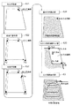
図面を用いて、本発明による走行経路生成装置を搭載した作業車の実施形態の1つを説明する。この実施形態では、作業車は、車体1に作業装置30を装備したトラクタである。最初に、トラクタはユーザによって運転され、圃場形状を算出するためのティーチング走行を行う。このティーチング走行では、トラクタは、農道から下向きに傾斜した出入口通路を通って、圃場内に進入し、畦によって区画された圃場の境界に沿って周回走行する。その際、後で詳しく説明するが、出入口通路の畦側の第1端点が始点Psとして位置登録され、圃場の形状を規定する形状特徴点が経過点P1、P2、P3として位置登録され、出入口通路の畦側の、第1端点と対向する第2端点が終点Peとして位置登録される。始点Psと経過点P1、P2、P3と終点Peとを結ぶ線によって圃場の基本形状が算出される。この圃場の基本形状から出入口通路を除外した領域が、作業対象領域と称せられる。さらに、出入口通路の形状を四角形と見なし、始点Psと終点Pe以外の頂点内作業対象領域に接する頂点を内点Paと定義し、作業対象領域から離れた頂点を外点Pbと定義する。
One of the embodiments of the work vehicle equipped with the travel path generation device according to the present invention will be described with reference to the drawings. In this embodiment, the work vehicle is a tractor equipped with a
図2に示されているように、このトラクタは、前輪11と後輪12とによって支持された車体1の中央部に運転室20が設けられている。車体1の後部には油圧式の昇降機構31を介してロータリ耕耘装置である作業装置30が装備されている。前輪11は操向輪として機能し、その操舵角を変更することでトラクタの走行方向が変更される。前輪11の操舵角は操舵機構13の動作によって変更される。操舵機構13には自動操舵のための操舵モータ14が含まれている。手動走行の際には、前輪11の操舵は運転室20に配置されているステアリングホイール22の操作によって行われる。運転室20には、ユーザによる指令を受け付けるとともにユーザに情報を提供する汎用端末4が装備されている。トラクタのキャビン21には、衛星測位モジュール80が設けられている。衛星測位モジュール80の構成要素として、GNSS(global navigation satellite system)信号(GPS信号を含む)を受信するための衛星用アンテナがキャビン21の天井領域に取り付けられている。なお、この衛星測位モジュール80に、衛星航法を補完するために、ジャイロ加速度センサや磁気方位センサを組み込んだ慣性航法モジュールを組み合わせることも可能である。もちろん、慣性航法モジュールは、衛星測位モジュール80とは別の場所に設けてもよい。
As shown in FIG. 2, this tractor is provided with a driver's
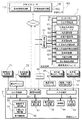
図3には、このトラクタに構築されている制御系が示されている。この実施形態の制御系は、グラフィカルユーザインターフェースを備えた汎用端末4である第1制御ユニットと、トラクタの車体1や作業装置30の制御を行う制御ユニット5と、トラクタの走行開始と走行停止とを外部から無線で制御するためのリモコン84とを備えている。本発明による走行経路生成装置は経路生成モジュール6としてモジュール化され、汎用端末4に組み込まれている。
FIG. 3 shows a control system built on this tractor. The control system of this embodiment includes a first control unit which is a general-
汎用端末4は、経路生成モジュール6以外に、通信制御部40、タッチパネル60、タッチパネル60に対する入力操作やタッチパネル60での情報表示を管理する入出力管理部61など、一般的なコンピュータシステムの諸機能を備えている。汎用端末4は、車載LAN、無線通信、有線通信などによって、制御ユニット5とデータ交換可能に接続されている。さらに、汎用端末4は、遠隔地の管理センタKSに構築された管理コンピュータ100とも、無線回線やインターネットを通じて、データ交換可能である。また、汎用端末4をタブレットコンピュータや携帯電話などで構成し、トラクタの制御系とデータ交換可能に接続すれば、汎用端末4をトラクタの外に持ち出して、使用することも可能である。
In addition to the route generation module 6, the general-
この実施形態では、圃場の地図上の位置や圃場を取り巻く農道等の配置などを含む圃場情報が、管理コンピュータ100の圃場情報格納部101に格納されており、この圃場情報は、作業すべき圃場を見つけ出すために必要となる。管理コンピュータ100は、指定された圃場での作業内容を記述した作業計画書を管理している作業計画管理部102も備えている。汎用端末4は、管理コンピュータ100にアクセスし、圃場情報格納部101から圃場情報を、そして作業計画管理部102から作業計画書をダウンロードすることができる。あるいは、汎用端末4は、USBメモリなどの記録媒体を通じて圃場情報や作業計画書を入力することも可能である。
In this embodiment, field information including the position on the map of the field and the arrangement of farm roads surrounding the field is stored in the field
経路生成モジュール6は、ティーチング走行を通じて、圃場の作業有効領域である作業対象領域の形状を算出する作業地形状算出サブモジュール62と、当該作業対象領域をトラクタが走行するための走行経路を生成する走行経路生成部63とを備えている。作業地形状算出サブモジュール62には、始点登録部621、経過点登録部622、終点登録部623、基本形状算出部624、出入口通路情報生成部625、形状編集部626が含まれている。さらに、オプションとして内点登録部627も用意されている。
The route generation module 6 generates a work area
次に、図4に示されている、圃場形状算出処理及び走行経路生成処理の流れ図を用いて、経路生成モジュール6の各機能部の基本的な役割を説明する。図4では、圃場の形状は台形で、上辺右端に下向き傾斜した出入口通路が設けられている。さらに、図5で示すように、トラクタの4つのコーナ部に照準点T1、T2、T3,T4が規定されており、これらの照準点T1、T2、T3,T4と、衛星測位モジュール80からの測位データに基づく自車位置(図5では、車体中央の黒丸で示されている)との間の距離が予め設定されており、各照準点T1、T2、T3,T4の位置座標が、自車位置から算出可能である。タッチパネル60には、照準点選択ボタンB1、B2、B3,B4が表示され、押された照準点選択ボタンB1、B2、B3,B4に対応する照準点が、以下の圃場形状算出処理で有効となる。
Next, the basic role of each functional unit of the route generation module 6 will be described with reference to the flow chart of the field shape calculation process and the travel route generation process shown in FIG. In FIG. 4, the shape of the field is trapezoidal, and a downwardly inclined entrance / exit passage is provided at the right end of the upper side. Further, as shown in FIG. 5, aiming points T1, T2, T3, and T4 are defined at the four corners of the tractor, and these aiming points T1, T2, T3, and T4 and the
農道を通って、目的の圃場に到着したトラクタは、当該圃場の形状を算出するために、ティーチング走行を行う。ここでは、照準点選択ボタンB1が押され、照準点T1を有効となっている。 The tractor arriving at the target field through the farm road performs a teaching run in order to calculate the shape of the field. Here, the aiming point selection button B1 is pressed, and the aiming point T1 is enabled.
まず、運転者は、出入口通路を通り、出入口通路を下った右側の端部(第1端点)に照準点T1がくるようにトラクタを操縦し、タッチパネル60に表示された登録ボタンRB(図5参照)を押す。これにより、始点登録部621は、第1端点を始点(図4で黒丸とPsで示されている)として登録する。
First, the driver steers the tractor so that the aiming point T1 comes to the right end (first end point) that passes through the doorway and goes down the doorway, and the registration button RB displayed on the touch panel 60 (FIG. 5). See). As a result, the start
次に、運転者は、圃場の形状特徴点(幾何形状体、ここでは台形の頂点)である上辺左端に照準点T1がくるようにトラクタを進め、登録ボタンRBを押す。これにより、経過点登録部622は、上辺左端を第1経過点(図4で黒丸とP1で示されている)として登録する。さらに、下辺左端に照準点T1がくるようにトラクタを進め、登録ボタンRBを押す。これにより、経過点登録部622は、下辺左端を第2経過点(図4で黒丸とP2で示されている)として登録する。さらに、下辺右端に照準点T1がくるようにトラクタを進め、登録ボタンRBを押す。これにより、経過点登録部622は、下辺右端を第3経過点(図4で黒丸とP3で示されている)として登録する。
Next, the driver advances the tractor so that the aiming point T1 comes to the left end of the upper side, which is the shape feature point (geometric shape body, in this case, the apex of the trapezoid) of the field, and presses the registration button RB. As a result, the elapsed
次に、運転者は、第3経過点を設定した圃場の下辺右端から畦(境界)に沿ってトラクタを進め、出入口通路と境界との交点となる端点に照準点T1がくる位置でトラクタを停止させ、登録ボタンRBを押す。終点登録部623は、登録ボタンRBが押された位置が始点と近接しているので、この位置を終点(図4で黒丸とPeで示されている)とみなして登録する。あるいは、運転者が終点を示す指示操作を行った後に登録ボタンRBを押すことで、登録位置が終点であることを終点登録部623に指令してもよい。
Next, the driver advances the tractor along the ridge (boundary) from the lower right end of the field where the third passage point is set, and moves the tractor at the position where the aiming point T1 comes to the end point that is the intersection of the entrance passage and the boundary. Stop and press the registration button RB. Since the position where the registration button RB is pressed is close to the start point, the end
これにより、始点と3つの経過点と終点との位置座標が得られたので、基本形状算出部624はこれらの点を結ぶことで、作業地の基本形状を算出する。
As a result, the position coordinates of the start point, the three elapsed points, and the end point are obtained, and the basic
続いて、出入口通路情報生成部625は、出入口通路の形状寸法や出入口通路の走行方向などの出入口通路情報を生成する。図4に示されているように、出入口通路は、部分的な通路であるので、実質的には四角形とみなして差し支えない。この出入口通路を示す四角形の2つの対頂点は、始点と終点である(図4で黒丸とPs、Peで示されている)。したがって、あと2つの頂点を求めることで出入口通路の形状寸法が得られる。そこで、この出入口通路を示す四角形が隣接する圃場の境界線の延長線(作業地基本形状の外形延長線)を2辺とする平行四辺形(長方形や正方形を含む)とみなすと、圃場内側の頂点(外点と称する)と圃場外側の頂点(内点と称する)の位置座標は、幾何学的な演算で簡単に求めることができる。図4では、内点は白丸とPaで示され、外点は白丸とPbで示されている。さらに、外点と終点とを結ぶ辺から始点と内点とを結ぶ辺に向かう方向がトラクタの圃場内部への進入方向(走行方向)であると見なすことができる。
Subsequently, the entrance / exit passage
始点と3つの経過点と終点と内点とを結ぶことで得られる輪郭線によって、圃場における出入口通路以外の領域、つまり有効作業領域である作業対象領域が規定される。この輪郭線は、実質的には、トラクタの走行によって得られているので、必ずしも正確ではない。例えば、トラクタが走行できないような凹部や凸部があれば、そのような凹部や凸部は無視される。このため、始点と3つの経過点と終点と内点とを結ぶことで得られる輪郭線を修正する形状編集部626が備えられている。この形状編集部626は、タッチパネル60に表示された輪郭線を、例えばペジェ曲線の編集のような要領でユーザが編集することを可能にする。
The contour line obtained by connecting the start point, the three transition points, the end point, and the inner point defines an area other than the entrance / exit passage in the field, that is, a work target area which is an effective work area. This contour is not always accurate as it is essentially obtained by running the tractor. For example, if there are recesses or protrusions that prevent the tractor from traveling, such recesses or bumps are ignored. Therefore, a
なお、オプションである内点登録部627が利用可能な場合、終点の登録後に、さらに、運転者は、トラクタを、出入口通路と作業対象領域との境界線の内側の端点に出入口通路を下った右側の端部(第1端点)に照準点T1がくるようにトラクタを操縦し、照準点T1がくる位置でトラクタを停止させ、登録ボタンRBを押す。これにより内点登録部627は、当該位置を内点(図4で白丸とPaで示されている)として登録する。
If the optional interior
これまでの説明で、照準点T1だけが利用されていたが、その他の照準点T2、T3,T4の方が、目的の位置に接近しやすい場合がある。特に後進で接近する場合には、照準点T3,T4が好都合である。そのような場合には、照準点選択ボタンB1、B2、B3,B4から所望の照準点に対応するボタンを選んで押すことで、有効となる照準点が変更される。 In the explanation so far, only the aiming point T1 has been used, but other aiming points T2, T3, and T4 may be easier to approach the target position. The aiming points T3 and T4 are particularly convenient when approaching in reverse. In such a case, the effective aiming point is changed by selecting and pressing the button corresponding to the desired aiming point from the aiming point selection buttons B1, B2, B3, and B4.
作業対象領域が決定されると、走行経路生成部63が、当該作業対象領域を前記作業車が自動走行するための走行経路を生成する。生成される走行経路は、図4では、直進経路と各直進経路同士をつなぐUターン経路とからなる内側走行経路と、圃場の外周領域を周回走行するための周回走行経路とから構成されている。もちろん、これに代えて、圃場を渦巻き状に走行する渦巻き走行経路やその他の走行経路が生成されるアルゴリズムを採用してもよい。
When the work target area is determined, the travel
図3に示すように、トラクタの制御系の中核要素である制御ユニット5には、入出力インタフェースとして機能する、出力処理部7、入力処理部8、通信処理部70が備えられている。出力処理部7は、トラクタに装備されている、車両走行機器群71、作業装置機器群72、報知デバイス73などと接続している。車両走行機器群71には、操舵モータ14や、図示されていないが変速機構やエンジンユニットなど車両走行のために制御される機器が含まれている。作業装置機器群72には、作業装置30の駆動機構や、作業装置30を昇降させる昇降機構31などが含まれている。報知デバイス73には、ディスプレイやランプやスピーカが含まれている。報知デバイス73は、走行注意事項や自動操舵走行での目標走行経路からの外れなど、注意情報や警告情報を運転者や監視者に報知するために用いられる。通信処理部70は、制御ユニット5で処理されたデータを管理コンピュータ100に送信するとともに、管理コンピュータ100から種々のデータを受信する機能を有する。さらに、通信処理部70は、リモコン84からのリモコン指令を入力する。
As shown in FIG. 3, the control unit 5, which is a core element of the control system of the tractor, includes an output processing unit 7, an
入力処理部8は、衛星測位モジュール80、走行系検出センサ群81、作業系検出センサ群82、自動/手動切替操作具83などと接続している。走行系検出センサ群81には、エンジン回転数や変速状態などの走行状態を検出するセンサが含まれている。作業系検出センサ群82には、作業装置30の位置や傾きを検出するセンサ、作業負荷などを検出するセンサなどが含まれている。自動/手動切替操作具83は、自動操舵で走行する自動走行モードと手動操舵で走行する手動操舵モードとのいずれかを選択するスイッチである。
The
さらに、制御ユニット5には、走行制御部50、作業制御部54、自車位置算出部53、走行経路設定部55、報知部56が備えられている。自車位置算出部53は、衛星測位モジュール80から送られてくる測位データに基づいて、自車位置を算出する。上述したティーチング走行の実行中は、算出された自車位置は、作業地形状算出サブモジュールに与えられる。車両走行機器群71を制御する走行制御部50には、このトラクタが自動走行(自動操舵)と手動走行(手動操舵)の両方で走行可能に構成されているため、手動走行制御部51と自動走行制御部52とが含まれている。手動走行制御部51は、運転者による操作に基づいて車両走行機器群71を制御する。自動走行制御部52は、走行経路設定部55で設定された走行経路と自車位置との間の方位ずれ及び位置ずれを算出し、自動操舵指令を生成する。この自動操舵指令は、出力処理部7を介して操舵モータ14に出力される。自動走行制御部52は、リモコン84からの停止指令に基づいてトラクタを停止させるとともに、リモコン84からの開始指令に基づいてトラクタの走行を開始させる。作業制御部54は、作業装置30の動きを制御するために、作業装置機器群72に制御信号を与える。報知部56は、運転者や監視者に必要な情報を報知するための報知信号(表示データや音声データ)を生成して、計器パネルに組み込まれた報知デバイス73に与える。
Further, the control unit 5 is provided with a
走行経路設定部55は、経路生成モジュール6によって生成された走行経路を汎用端末4の走行経路生成部63から通信処理部70を介して受け取り、トラクタの目標走行経路として設定する。
The travel
〔別実施の形態〕
(1)上述した実施形態では、作業地の出入口の位置形状を算出し、作業地から出入口を除外した領域である作業対象領域を算出し、当該作業対象領域を自動走行するための走行経路を生成している。この実施形態に代えて、出入口とは無関係に、作業地における任意の領域の形状を作業対象領域として算出し、走行経路を生成する実施形態を採用してもよい。そのような走行経路生成装置では、経路生成モジュール6の作業地形状算出サブモジュール62において、出入口通路情報生成部625や内点登録部627が不要となる。
(2)上述した実施形態では、経路生成モジュール6は、実際の作業に用いられるトラクタに装備されており、照準点T1、T2、T3,T4も当該トラクタのコーナ部に規定されていた。これに代えて、トラクタ以外の別な車両、例えば、作業地(圃場)をより速い速度で走行可能で、衛星測位機能を備えた多目的車両に、経路生成モジュール6、または、作業地形状算出サブモジュール62を装備し、作業地(圃場)の形状を算出させてもよい。
(3)図3で示された機能ブロック図における各機能部は、主に説明目的で区分けされている。実際には、各機能部は他の機能部と統合または複数の機能部に分けることができる。例えば、経路生成モジュール6を、特に走行経路生成部63を作業車の制御ユニット5内に構築してもよい。
(4)上述した実施形態では、作業車として、ロータリ耕耘機を作業装置30として装備したトラクタを、作業車として取り上げたが、そのようなトラクタ以外にも、例えば、田植機、施肥機、コンバインなどの農作業車にも適用可能である。
[Another embodiment]
(1) In the above-described embodiment, the position and shape of the entrance / exit of the work area are calculated, the work target area which is the area excluding the entrance / exit from the work area is calculated, and the traveling route for automatically traveling in the work target area is calculated. It is generating. Instead of this embodiment, an embodiment may be adopted in which the shape of an arbitrary region in the work area is calculated as the work target region and a traveling route is generated regardless of the entrance / exit. In such a traveling route generation device, the entrance / exit passage
(2) In the above-described embodiment, the route generation module 6 is mounted on the tractor used in the actual work, and the aiming points T1, T2, T3, and T4 are also defined in the corner portion of the tractor. Instead of this, a route generation module 6 or a work site shape calculation sub The
(3) Each functional unit in the functional block diagram shown in FIG. 3 is mainly divided for explanatory purposes. In practice, each functional unit can be integrated with other functional units or divided into a plurality of functional units. For example, the route generation module 6 may be constructed in particular, the travel
(4) In the above-described embodiment, a tractor equipped with a rotary tiller as a
本発明による走行経路生成装置は、設定された走行経路に沿って作業地を作業する作業車のために適用可能である。 The travel route generation device according to the present invention is applicable to a work vehicle that works on a work site along a set travel route.
5 :制御ユニット
50 :走行制御部
53 :自車位置算出部
55 :走行経路設定部
80 :衛星測位モジュール
6 :経路生成モジュール
60 :タッチパネル
61 :入出力管理部
62 :作業地形状算出サブモジュール
621 :始点登録部
622 :経過点登録部
623 :終点登録部
624 :基本形状算出部
625 :出入口通路情報生成部
626 :形状編集部
627 :内点登録部
63 :走行経路生成部
Ps :始点
P1 :経過点
P2 :経過点
P3 :経過点
Pe :終点
Pa :内点
Pb :外点
5: Control unit 50: Travel control unit 53: Own vehicle position calculation unit 55: Travel route setting unit 80: Satellite positioning module 6: Route generation module 60: Touch panel 61: Input / output management unit 62: Work site shape calculation submodule 621 : Start point registration unit 622: Progress point registration unit 623: End point registration unit 624: Basic shape calculation unit 625: I / O passage information generation unit 626: Shape editing unit 627: Internal point registration unit 63: Travel path generation unit Ps: Start point P1: Progression point P2: Progression point P3: Progression point Pe: End point Pa: Inner point Pb: Outer point
Claims (6)
前記出入口通路の前記境界側の第1端点を始点として位置登録する始点登録部と、
前記作業地の形状を規定する形状特徴点を経過点として位置登録する経過点登録部と、
前記出入口通路の前記境界側の、前記第1端点と対向する第2端点を終点として位置登録する終点登録部と、
前記始点の位置と前記経過点の位置と前記終点の位置とを結ぶことで前記作業地の基本形状を算出する基本形状算出部と、
前記始点と前記終点とを対頂点とするとともに前記基本形状の外形延長線に沿った2辺を有する四角形を前記出入口通路の形状として出入口通路情報を生成する出入口通路情報生成部と、
前記作業地の前記出入口通路以外の領域を作業対象領域とし、当該作業対象領域を前記作業車が自動走行するための走行経路を生成する走行経路生成部と、を備え、
前記始点、前記経過点、及び前記終点の位置は、前記作業車に搭載された衛星測位モジュールからの測位データに基づく自車位置を利用して算出され、
前記出入口通路情報生成部は、前記出入口通路の形状を表す四角形の前記始点及び前記終点以外の頂点を、前記作業対象領域に接する内点と前記作業対象領域から離れた外点と定義し、前記外点と前記終点とを結ぶ辺から前記始点と前記内点とを結ぶ辺に向かう方向が前記作業車の前記作業対象領域への進入方向とする走行経路生成装置。 A travel route generator for work vehicles entering and exiting a work area partitioned by a boundary through an entrance / exit passage.
A start point registration unit that registers a position with the first end point on the boundary side of the entrance / exit passage as a start point, and a start point registration unit.
A transition point registration unit that registers the position of a shape feature point that defines the shape of the work site as a transition point,
An end point registration unit that registers a position with a second end point facing the first end point on the boundary side of the entrance / exit passage as an end point.
A basic shape calculation unit that calculates the basic shape of the work site by connecting the position of the start point, the position of the elapsed point, and the position of the end point.
An entrance / exit passage information generation unit that generates entrance / exit passage information by using a quadrangle having two sides along the outer extension line of the basic shape as a pair of vertices with the start point and the end point as the shape of the entrance / exit passage.
An area other than the entrance / exit passage of the work area is set as a work target area, and a travel route generation unit for generating a travel route for the work vehicle to automatically travel in the work target area is provided.
The positions of the start point, the elapsed point, and the end point are calculated by using the position of the own vehicle based on the positioning data from the satellite positioning module mounted on the work vehicle.
The entrance / exit passage information generation unit defines the vertices other than the start point and the end point of the quadrangle representing the shape of the entrance / exit passage as an inner point in contact with the work target area and an outer point away from the work target area. A travel route generation device in which the direction from the side connecting the outer point and the end point to the side connecting the start point and the inner point is the approach direction of the work vehicle to the work target area.
能である請求項4に記載の走行経路生成装置。 The traveling route generation device according to claim 4 , wherein a plurality of the aiming points are defined, and an effective aiming point can be selected from the plurality of aiming points.
前記出入口通路の前記境界側の第1端点を始点として位置登録する始点登録機能と、
前記作業地の形状を規定する形状特徴点を経過点として位置登録する経過点登録機能と、
前記出入口通路の前記境界側の、前記第1端点と対向する第2端点を終点として位置登録する終点登録機能と、
前記始点の位置と前記経過点の位置と前記終点の位置とを結ぶことで前記作業地の基本形状を算出する基本形状算出機能と、
前記始点と前記終点とを対頂点とするとともに前記基本形状の外形延長線に沿った2辺を有する四角形を前記出入口通路の形状として出入口通路情報を生成する出入口通路情報生成機能と、
前記作業地の前記出入口通路以外の領域を作業対象領域とし、当該作業対象領域を前記作業車が自動走行するための走行経路を生成する走行経路生成機能と、
前記始点、前記経過点、及び前記終点の位置を、前記作業車に搭載された衛星測位モジュールからの測位データに基づく自車位置を利用して算出する機能と、
前記出入口通路の形状を表す四角形の前記始点及び前記終点以外の頂点を、前記作業対象領域に接する内点と前記作業対象領域から離れた外点と定義し、前記外点と前記終点とを結ぶ辺から前記始点と前記内点とを結ぶ辺に向かう方向が前記作業車の前記作業対象領域への進入方向とする機能と、をコンピュータに実現させる走行経路生成プログラム。
It is a travel route generation program for work vehicles that enter and exit the work area partitioned by the boundary through the entrance passage.
A start point registration function for registering a position with the first end point on the boundary side of the entrance / exit passage as a start point, and
A transition point registration function that registers the position of a shape feature point that defines the shape of the work site as a transition point, and
An end point registration function for registering a position with a second end point facing the first end point on the boundary side of the entrance / exit passage as an end point,
A basic shape calculation function that calculates the basic shape of the work site by connecting the position of the start point, the position of the elapsed point, and the position of the end point.
An entrance / exit passage information generation function that generates entrance / exit passage information by using a quadrangle having two sides along the outer extension line of the basic shape as a pair of vertices with the start point and the end point as the shape of the entrance / exit passage.
A travel route generation function that generates a travel route for the work vehicle to automatically travel in the work target area by setting an area other than the entrance / exit passage of the work site as the work target area.
A function to calculate the positions of the start point, the elapsed point, and the end point by using the position of the own vehicle based on the positioning data from the satellite positioning module mounted on the work vehicle.
Vertices other than the start point and the end point of the quadrangle representing the shape of the entrance / exit passage are defined as an inner point in contact with the work target area and an outer point away from the work target area, and connect the outer point and the end point. A travel route generation program that enables a computer to realize a function in which the direction from the side toward the side connecting the start point and the inner point is the approach direction of the work vehicle to the work target area.
Priority Applications (7)
| Application Number | Priority Date | Filing Date | Title |
|---|---|---|---|
| JP2017008344A JP6971577B2 (en) | 2017-01-20 | 2017-01-20 | Travel route generator and travel route generation program |
| CN201710398228.4A CN108334065B (en) | 2017-01-20 | 2017-05-31 | Travel route generation device and travel route generation program |
| KR1020170067886A KR102398388B1 (en) | 2017-01-20 | 2017-05-31 | Traveling route producing device and traveling route producing program |
| US15/624,715 US20180210456A1 (en) | 2017-01-20 | 2017-06-16 | Travel route generation device and travel route generation method |
| EP17001059.9A EP3351077B1 (en) | 2017-01-20 | 2017-06-21 | Travel route generation device and travel route generation program |
| US16/395,249 US10989541B2 (en) | 2017-01-20 | 2019-04-26 | Travel route generation device and travel route generation method |
| JP2021132710A JP7209783B2 (en) | 2017-01-20 | 2021-08-17 | Driving route generation device and driving route generation program |
Applications Claiming Priority (1)
| Application Number | Priority Date | Filing Date | Title |
|---|---|---|---|
| JP2017008344A JP6971577B2 (en) | 2017-01-20 | 2017-01-20 | Travel route generator and travel route generation program |
Related Child Applications (1)
| Application Number | Title | Priority Date | Filing Date |
|---|---|---|---|
| JP2021132710A Division JP7209783B2 (en) | 2017-01-20 | 2021-08-17 | Driving route generation device and driving route generation program |
Publications (2)
| Publication Number | Publication Date |
|---|---|
| JP2018116608A JP2018116608A (en) | 2018-07-26 |
| JP6971577B2 true JP6971577B2 (en) | 2021-11-24 |
Family
ID=59152620
Family Applications (2)
| Application Number | Title | Priority Date | Filing Date |
|---|---|---|---|
| JP2017008344A Active JP6971577B2 (en) | 2017-01-20 | 2017-01-20 | Travel route generator and travel route generation program |
| JP2021132710A Active JP7209783B2 (en) | 2017-01-20 | 2021-08-17 | Driving route generation device and driving route generation program |
Family Applications After (1)
| Application Number | Title | Priority Date | Filing Date |
|---|---|---|---|
| JP2021132710A Active JP7209783B2 (en) | 2017-01-20 | 2021-08-17 | Driving route generation device and driving route generation program |
Country Status (4)
| Country | Link |
|---|---|
| EP (1) | EP3351077B1 (en) |
| JP (2) | JP6971577B2 (en) |
| KR (1) | KR102398388B1 (en) |
| CN (1) | CN108334065B (en) |
Families Citing this family (21)
| Publication number | Priority date | Publication date | Assignee | Title |
|---|---|---|---|---|
| WO2020026650A1 (en) * | 2018-08-01 | 2020-02-06 | 株式会社クボタ | Automatic travel control system, automatic travel control method, automatic travel control program, and storage medium |
| JP7130535B2 (en) * | 2018-08-01 | 2022-09-05 | 株式会社クボタ | automatic driving control system |
| JP7019057B2 (en) * | 2018-09-06 | 2022-02-14 | 本田技研工業株式会社 | Route subdivision device |
| CN112912808B (en) * | 2018-10-22 | 2023-12-26 | 株式会社尼罗沃克 | Travel path generation system, travel path generation method, computer-readable recording medium, coordinate measurement system, and unmanned aerial vehicle |
| JP7120907B2 (en) * | 2018-12-20 | 2022-08-17 | 株式会社クボタ | traveling work machine |
| JP7175743B2 (en) * | 2018-12-21 | 2022-11-21 | 株式会社クボタ | Automatic travel control system for planting and seeding equipment |
| JP7069002B2 (en) * | 2018-12-21 | 2022-05-17 | 株式会社クボタ | Field work vehicle and field map data generation system |
| JP7173858B2 (en) * | 2018-12-21 | 2022-11-16 | 株式会社クボタ | Planting system work machine and automatic travel control system for planting system work machine |
| KR20200078359A (en) | 2018-12-21 | 2020-07-01 | 가부시끼 가이샤 구보다 | Planting work machine and automatic traveling control system for planting work machine, field work vehicle and travel route generation system |
| JP7134860B2 (en) | 2018-12-26 | 2022-09-12 | 株式会社クボタ | work vehicle |
| JP7130549B2 (en) | 2018-12-26 | 2022-09-05 | 株式会社クボタ | Work vehicle and work machine with work vehicle |
| JP7096531B2 (en) * | 2018-12-27 | 2022-07-06 | 井関農機株式会社 | Autonomous driving system for work vehicles |
| CN110366913A (en) * | 2019-04-04 | 2019-10-25 | 丰疆智能科技股份有限公司 | Rice transplanter and its rice transplanting method and rice seedlings transplanting system |
| JP7242446B2 (en) * | 2019-06-28 | 2023-03-20 | 株式会社クボタ | work support system, work vehicle |
| CN110502010B (en) * | 2019-08-15 | 2021-06-04 | 同济大学 | Mobile robot indoor autonomous navigation control method based on Bezier curve |
| JP7413031B2 (en) * | 2020-01-14 | 2024-01-15 | 株式会社クボタ | work equipment |
| JP7386394B2 (en) * | 2020-05-22 | 2023-11-27 | 井関農機株式会社 | Work vehicle monitoring and control system |
| CN111766870B (en) * | 2020-05-29 | 2021-11-05 | 广州极飞科技股份有限公司 | Transition path and operation path planning method and related device |
| CN112783159A (en) * | 2020-12-28 | 2021-05-11 | 上海联适导航技术股份有限公司 | Operation control method, device, equipment and readable storage medium |
| JP7466201B2 (en) | 2021-02-19 | 2024-04-12 | 国立研究開発法人農業・食品産業技術総合研究機構 | Travel route setting device, travel route setting method, and travel route setting program for farm work vehicle |
| JP7416437B2 (en) | 2021-03-26 | 2024-01-17 | 国立研究開発法人農業・食品産業技術総合研究機構 | Traveling route setting device, traveling route setting method, and traveling route setting program for field work vehicles |
Family Cites Families (17)
| Publication number | Priority date | Publication date | Assignee | Title |
|---|---|---|---|---|
| JPH07281742A (en) * | 1994-04-04 | 1995-10-27 | Kubota Corp | Traveling controller for beam light guided work vehicle |
| JP3656332B2 (en) * | 1996-08-28 | 2005-06-08 | 独立行政法人農業・生物系特定産業技術研究機構 | Unmanned work method by unmanned working vehicle |
| JP3814230B2 (en) * | 2002-06-05 | 2006-08-23 | ヤンマー農機株式会社 | Agricultural sprayer |
| US6934615B2 (en) * | 2003-03-31 | 2005-08-23 | Deere & Company | Method and system for determining an efficient vehicle path |
| US7216033B2 (en) * | 2003-03-31 | 2007-05-08 | Deere & Company | Path planner and method for planning a contour path of a vehicle |
| JP4999965B2 (en) * | 2010-06-04 | 2012-08-15 | 中国電力株式会社 | Automatic cultivation method and automatic cultivation system |
| CN102167038B (en) * | 2010-12-03 | 2013-09-04 | 北京农业信息技术研究中心 | Method and device for generating all-region-covering optimal working path for farmland plot |
| JP5785415B2 (en) * | 2011-03-29 | 2015-09-30 | 株式会社デンソーアイティーラボラトリ | Route guidance generating apparatus, method and system |
| CN103430050B (en) * | 2011-04-15 | 2019-09-27 | 拜尔知识产权有限公司 | Visual information system and computer mobile application for Field Force |
| JP5807518B2 (en) * | 2011-11-09 | 2015-11-10 | 富士通株式会社 | Estimation apparatus, estimation method, and estimation program |
| CN102607582A (en) * | 2012-03-07 | 2012-07-25 | 深圳市赛格导航科技股份有限公司 | Method for planning guidance route by means of using city access points as guideposts and system |
| US10126754B2 (en) * | 2014-02-06 | 2018-11-13 | Yanmar Co., Ltd. | Method for setting travel path of work vehicle |
| JP6219790B2 (en) * | 2014-07-29 | 2017-10-25 | 株式会社クボタ | Work vehicle coordination system |
| JP6467897B2 (en) * | 2014-12-10 | 2019-02-13 | 井関農機株式会社 | Tractor |
| JP2016156690A (en) * | 2015-02-24 | 2016-09-01 | 井関農機株式会社 | Working vehicle |
| JP6569319B2 (en) * | 2015-06-17 | 2019-09-04 | 日本製鉄株式会社 | Abrasion-resistant steel plate and method for producing the same |
| AU2016287397B2 (en) * | 2015-06-30 | 2021-05-20 | Climate Llc | Systems and methods for image capture and analysis of agricultural fields |
-
2017
- 2017-01-20 JP JP2017008344A patent/JP6971577B2/en active Active
- 2017-05-31 CN CN201710398228.4A patent/CN108334065B/en active Active
- 2017-05-31 KR KR1020170067886A patent/KR102398388B1/en active IP Right Grant
- 2017-06-21 EP EP17001059.9A patent/EP3351077B1/en active Active
-
2021
- 2021-08-17 JP JP2021132710A patent/JP7209783B2/en active Active
Also Published As
| Publication number | Publication date |
|---|---|
| JP2018116608A (en) | 2018-07-26 |
| JP2021184300A (en) | 2021-12-02 |
| KR20180086108A (en) | 2018-07-30 |
| CN108334065B (en) | 2022-09-16 |
| EP3351077A1 (en) | 2018-07-25 |
| JP7209783B2 (en) | 2023-01-20 |
| EP3351077B1 (en) | 2020-04-01 |
| KR102398388B1 (en) | 2022-05-16 |
| CN108334065A (en) | 2018-07-27 |
Similar Documents
| Publication | Publication Date | Title |
|---|---|---|
| JP6971577B2 (en) | Travel route generator and travel route generation program | |
| JP6812247B2 (en) | Travel route generator and travel route generation program | |
| JP6872911B2 (en) | Travel route generator | |
| US10598505B2 (en) | Travel route generation apparatus and method for generating travel route | |
| JP2018073050A (en) | Running route creating device | |
| WO2017154772A1 (en) | Route generating device | |
| JP6727944B2 (en) | Field travel route generation system and field work vehicle | |
| JP6594805B2 (en) | Work vehicle | |
| JP2017161987A (en) | Travel area form registration system of work vehicle | |
| US20190249991A1 (en) | Travel route generation device and travel route generation method | |
| JP7069285B2 (en) | Field work vehicle | |
| JP2017204061A (en) | Autonomous travel route generation system | |
| JP2021099844A (en) | Travel region shape registration system | |
| JP6605375B2 (en) | Autonomous traveling work vehicle | |
| WO2021106389A1 (en) | Autonomous traveling control system | |
| JP7069002B2 (en) | Field work vehicle and field map data generation system | |
| JP6879896B2 (en) | Satellite positioning system for work platforms | |
| WO2021106361A1 (en) | Area registration system | |
| JP2024004952A (en) | Automatic travel work method, automatic travel work system and program |
Legal Events
| Date | Code | Title | Description |
|---|---|---|---|
| A621 | Written request for application examination |
Free format text: JAPANESE INTERMEDIATE CODE: A621 Effective date: 20190626 |
|
| A977 | Report on retrieval |
Free format text: JAPANESE INTERMEDIATE CODE: A971007 Effective date: 20200422 |
|
| A131 | Notification of reasons for refusal |
Free format text: JAPANESE INTERMEDIATE CODE: A131 Effective date: 20200519 |
|
| A521 | Request for written amendment filed |
Free format text: JAPANESE INTERMEDIATE CODE: A523 Effective date: 20200716 |
|
| A02 | Decision of refusal |
Free format text: JAPANESE INTERMEDIATE CODE: A02 Effective date: 20201006 |
|
| A521 | Request for written amendment filed |
Free format text: JAPANESE INTERMEDIATE CODE: A523 Effective date: 20201223 |
|
| C60 | Trial request (containing other claim documents, opposition documents) |
Free format text: JAPANESE INTERMEDIATE CODE: C60 Effective date: 20201223 |
|
| A521 | Request for written amendment filed |
Free format text: JAPANESE INTERMEDIATE CODE: A821 Effective date: 20201224 |
|
| A911 | Transfer to examiner for re-examination before appeal (zenchi) |
Free format text: JAPANESE INTERMEDIATE CODE: A911 Effective date: 20210129 |
|
| C21 | Notice of transfer of a case for reconsideration by examiners before appeal proceedings |
Free format text: JAPANESE INTERMEDIATE CODE: C21 Effective date: 20210202 |
|
| A912 | Re-examination (zenchi) completed and case transferred to appeal board |
Free format text: JAPANESE INTERMEDIATE CODE: A912 Effective date: 20210305 |
|
| C211 | Notice of termination of reconsideration by examiners before appeal proceedings |
Free format text: JAPANESE INTERMEDIATE CODE: C211 Effective date: 20210309 |
|
| C22 | Notice of designation (change) of administrative judge |
Free format text: JAPANESE INTERMEDIATE CODE: C22 Effective date: 20210518 |
|
| C302 | Record of communication |
Free format text: JAPANESE INTERMEDIATE CODE: C302 Effective date: 20210610 |
|
| C13 | Notice of reasons for refusal |
Free format text: JAPANESE INTERMEDIATE CODE: C13 Effective date: 20210622 |
|
| A521 | Request for written amendment filed |
Free format text: JAPANESE INTERMEDIATE CODE: A523 Effective date: 20210817 |
|
| C23 | Notice of termination of proceedings |
Free format text: JAPANESE INTERMEDIATE CODE: C23 Effective date: 20210831 |
|
| C03 | Trial/appeal decision taken |
Free format text: JAPANESE INTERMEDIATE CODE: C03 Effective date: 20211005 |
|
| C30A | Notification sent |
Free format text: JAPANESE INTERMEDIATE CODE: C3012 Effective date: 20211005 |
|
| A61 | First payment of annual fees (during grant procedure) |
Free format text: JAPANESE INTERMEDIATE CODE: A61 Effective date: 20211102 |
|
| R150 | Certificate of patent or registration of utility model |
Ref document number: 6971577 Country of ref document: JP Free format text: JAPANESE INTERMEDIATE CODE: R150 |