WO2017203934A1 - ガス発生器 - Google Patents
ガス発生器 Download PDFInfo
- Publication number
- WO2017203934A1 WO2017203934A1 PCT/JP2017/016926 JP2017016926W WO2017203934A1 WO 2017203934 A1 WO2017203934 A1 WO 2017203934A1 JP 2017016926 W JP2017016926 W JP 2017016926W WO 2017203934 A1 WO2017203934 A1 WO 2017203934A1
- Authority
- WO
- WIPO (PCT)
- Prior art keywords
- cup
- peripheral wall
- shaped member
- filter
- wall portion
- Prior art date
- Legal status (The legal status is an assumption and is not a legal conclusion. Google has not performed a legal analysis and makes no representation as to the accuracy of the status listed.)
- Ceased
Links
Images


Classifications
-
- B—PERFORMING OPERATIONS; TRANSPORTING
- B60—VEHICLES IN GENERAL
- B60R—VEHICLES, VEHICLE FITTINGS, OR VEHICLE PARTS, NOT OTHERWISE PROVIDED FOR
- B60R21/00—Arrangements or fittings on vehicles for protecting or preventing injuries to occupants or pedestrians in case of accidents or other traffic risks
- B60R21/02—Occupant safety arrangements or fittings, e.g. crash pads
- B60R21/16—Inflatable occupant restraints or confinements designed to inflate upon impact or impending impact, e.g. air bags
- B60R21/26—Inflatable occupant restraints or confinements designed to inflate upon impact or impending impact, e.g. air bags characterised by the inflation fluid source or means to control inflation fluid flow
- B60R21/264—Inflatable occupant restraints or confinements designed to inflate upon impact or impending impact, e.g. air bags characterised by the inflation fluid source or means to control inflation fluid flow using instantaneous generation of gas, e.g. pyrotechnic
-
- B—PERFORMING OPERATIONS; TRANSPORTING
- B01—PHYSICAL OR CHEMICAL PROCESSES OR APPARATUS IN GENERAL
- B01J—CHEMICAL OR PHYSICAL PROCESSES, e.g. CATALYSIS OR COLLOID CHEMISTRY; THEIR RELEVANT APPARATUS
- B01J7/00—Apparatus for generating gases
-
- B—PERFORMING OPERATIONS; TRANSPORTING
- B60—VEHICLES IN GENERAL
- B60R—VEHICLES, VEHICLE FITTINGS, OR VEHICLE PARTS, NOT OTHERWISE PROVIDED FOR
- B60R21/00—Arrangements or fittings on vehicles for protecting or preventing injuries to occupants or pedestrians in case of accidents or other traffic risks
- B60R21/02—Occupant safety arrangements or fittings, e.g. crash pads
- B60R21/16—Inflatable occupant restraints or confinements designed to inflate upon impact or impending impact, e.g. air bags
- B60R21/20—Arrangements for storing inflatable members in their non-use or deflated condition; Arrangement or mounting of air bag modules or components
- B60R21/217—Inflation fluid source retainers, e.g. reaction canisters; Connection of bags, covers, diffusers or inflation fluid sources therewith or together
- B60R21/2176—Inflation fluid source retainers, e.g. reaction canisters; Connection of bags, covers, diffusers or inflation fluid sources therewith or together the air bag components being completely enclosed in a soft or semi-rigid housing or cover
-
- B—PERFORMING OPERATIONS; TRANSPORTING
- B60—VEHICLES IN GENERAL
- B60R—VEHICLES, VEHICLE FITTINGS, OR VEHICLE PARTS, NOT OTHERWISE PROVIDED FOR
- B60R21/00—Arrangements or fittings on vehicles for protecting or preventing injuries to occupants or pedestrians in case of accidents or other traffic risks
- B60R21/02—Occupant safety arrangements or fittings, e.g. crash pads
- B60R21/16—Inflatable occupant restraints or confinements designed to inflate upon impact or impending impact, e.g. air bags
- B60R21/23—Inflatable members
- B60R21/231—Inflatable members characterised by their shape, construction or spatial configuration
- B60R21/2334—Expansion control features
- B60R21/2346—Soft diffusers
-
- B—PERFORMING OPERATIONS; TRANSPORTING
- B60—VEHICLES IN GENERAL
- B60R—VEHICLES, VEHICLE FITTINGS, OR VEHICLE PARTS, NOT OTHERWISE PROVIDED FOR
- B60R21/00—Arrangements or fittings on vehicles for protecting or preventing injuries to occupants or pedestrians in case of accidents or other traffic risks
- B60R21/02—Occupant safety arrangements or fittings, e.g. crash pads
- B60R21/16—Inflatable occupant restraints or confinements designed to inflate upon impact or impending impact, e.g. air bags
- B60R21/26—Inflatable occupant restraints or confinements designed to inflate upon impact or impending impact, e.g. air bags characterised by the inflation fluid source or means to control inflation fluid flow
- B60R21/261—Inflatable occupant restraints or confinements designed to inflate upon impact or impending impact, e.g. air bags characterised by the inflation fluid source or means to control inflation fluid flow with means other than bag structure to diffuse or guide inflation fluid
-
- B—PERFORMING OPERATIONS; TRANSPORTING
- B60—VEHICLES IN GENERAL
- B60R—VEHICLES, VEHICLE FITTINGS, OR VEHICLE PARTS, NOT OTHERWISE PROVIDED FOR
- B60R21/00—Arrangements or fittings on vehicles for protecting or preventing injuries to occupants or pedestrians in case of accidents or other traffic risks
- B60R21/02—Occupant safety arrangements or fittings, e.g. crash pads
- B60R21/16—Inflatable occupant restraints or confinements designed to inflate upon impact or impending impact, e.g. air bags
- B60R21/26—Inflatable occupant restraints or confinements designed to inflate upon impact or impending impact, e.g. air bags characterised by the inflation fluid source or means to control inflation fluid flow
- B60R21/261—Inflatable occupant restraints or confinements designed to inflate upon impact or impending impact, e.g. air bags characterised by the inflation fluid source or means to control inflation fluid flow with means other than bag structure to diffuse or guide inflation fluid
- B60R21/262—Elongated tubular diffusers, e.g. curtain-type
-
- B—PERFORMING OPERATIONS; TRANSPORTING
- B60—VEHICLES IN GENERAL
- B60R—VEHICLES, VEHICLE FITTINGS, OR VEHICLE PARTS, NOT OTHERWISE PROVIDED FOR
- B60R21/00—Arrangements or fittings on vehicles for protecting or preventing injuries to occupants or pedestrians in case of accidents or other traffic risks
- B60R21/02—Occupant safety arrangements or fittings, e.g. crash pads
- B60R21/16—Inflatable occupant restraints or confinements designed to inflate upon impact or impending impact, e.g. air bags
- B60R21/26—Inflatable occupant restraints or confinements designed to inflate upon impact or impending impact, e.g. air bags characterised by the inflation fluid source or means to control inflation fluid flow
- B60R21/264—Inflatable occupant restraints or confinements designed to inflate upon impact or impending impact, e.g. air bags characterised by the inflation fluid source or means to control inflation fluid flow using instantaneous generation of gas, e.g. pyrotechnic
- B60R21/2644—Inflatable occupant restraints or confinements designed to inflate upon impact or impending impact, e.g. air bags characterised by the inflation fluid source or means to control inflation fluid flow using instantaneous generation of gas, e.g. pyrotechnic using only solid reacting substances, e.g. pellets, powder
-
- B—PERFORMING OPERATIONS; TRANSPORTING
- B60—VEHICLES IN GENERAL
- B60R—VEHICLES, VEHICLE FITTINGS, OR VEHICLE PARTS, NOT OTHERWISE PROVIDED FOR
- B60R21/00—Arrangements or fittings on vehicles for protecting or preventing injuries to occupants or pedestrians in case of accidents or other traffic risks
- B60R21/02—Occupant safety arrangements or fittings, e.g. crash pads
- B60R21/16—Inflatable occupant restraints or confinements designed to inflate upon impact or impending impact, e.g. air bags
- B60R21/26—Inflatable occupant restraints or confinements designed to inflate upon impact or impending impact, e.g. air bags characterised by the inflation fluid source or means to control inflation fluid flow
- B60R2021/26011—Inflatable occupant restraints or confinements designed to inflate upon impact or impending impact, e.g. air bags characterised by the inflation fluid source or means to control inflation fluid flow using a filter through which the inflation gas passes
-
- B—PERFORMING OPERATIONS; TRANSPORTING
- B60—VEHICLES IN GENERAL
- B60R—VEHICLES, VEHICLE FITTINGS, OR VEHICLE PARTS, NOT OTHERWISE PROVIDED FOR
- B60R21/00—Arrangements or fittings on vehicles for protecting or preventing injuries to occupants or pedestrians in case of accidents or other traffic risks
- B60R21/02—Occupant safety arrangements or fittings, e.g. crash pads
- B60R21/16—Inflatable occupant restraints or confinements designed to inflate upon impact or impending impact, e.g. air bags
- B60R21/26—Inflatable occupant restraints or confinements designed to inflate upon impact or impending impact, e.g. air bags characterised by the inflation fluid source or means to control inflation fluid flow
- B60R2021/26029—Ignitors
-
- B—PERFORMING OPERATIONS; TRANSPORTING
- B60—VEHICLES IN GENERAL
- B60R—VEHICLES, VEHICLE FITTINGS, OR VEHICLE PARTS, NOT OTHERWISE PROVIDED FOR
- B60R21/00—Arrangements or fittings on vehicles for protecting or preventing injuries to occupants or pedestrians in case of accidents or other traffic risks
- B60R21/02—Occupant safety arrangements or fittings, e.g. crash pads
- B60R21/16—Inflatable occupant restraints or confinements designed to inflate upon impact or impending impact, e.g. air bags
- B60R21/26—Inflatable occupant restraints or confinements designed to inflate upon impact or impending impact, e.g. air bags characterised by the inflation fluid source or means to control inflation fluid flow
- B60R2021/26029—Ignitors
- B60R2021/26041—Ignitors of elongated shape
-
- B—PERFORMING OPERATIONS; TRANSPORTING
- B60—VEHICLES IN GENERAL
- B60R—VEHICLES, VEHICLE FITTINGS, OR VEHICLE PARTS, NOT OTHERWISE PROVIDED FOR
- B60R21/00—Arrangements or fittings on vehicles for protecting or preventing injuries to occupants or pedestrians in case of accidents or other traffic risks
- B60R21/02—Occupant safety arrangements or fittings, e.g. crash pads
- B60R21/16—Inflatable occupant restraints or confinements designed to inflate upon impact or impending impact, e.g. air bags
- B60R21/26—Inflatable occupant restraints or confinements designed to inflate upon impact or impending impact, e.g. air bags characterised by the inflation fluid source or means to control inflation fluid flow
- B60R21/264—Inflatable occupant restraints or confinements designed to inflate upon impact or impending impact, e.g. air bags characterised by the inflation fluid source or means to control inflation fluid flow using instantaneous generation of gas, e.g. pyrotechnic
- B60R21/2644—Inflatable occupant restraints or confinements designed to inflate upon impact or impending impact, e.g. air bags characterised by the inflation fluid source or means to control inflation fluid flow using instantaneous generation of gas, e.g. pyrotechnic using only solid reacting substances, e.g. pellets, powder
- B60R2021/2648—Inflatable occupant restraints or confinements designed to inflate upon impact or impending impact, e.g. air bags characterised by the inflation fluid source or means to control inflation fluid flow using instantaneous generation of gas, e.g. pyrotechnic using only solid reacting substances, e.g. pellets, powder comprising a plurality of combustion chambers or sub-chambers
Definitions
- the present invention relates to a gas generator that can be used in an airbag device mounted on an automobile.
- Some gas generators containing a gas generating agent as a gas generation source include a filter for filtering and cooling combustion gas.
- JP 2014-184427 A is an invention of a hybrid gas generator.
- a structure is disclosed in which a filter 60 is disposed in the vicinity of the gas outlet in the vicinity of the diffuser portion 150 serving as the gas outlet and inside the pressurized chamber housing 22 filled with the pressurized gas.
- the filter 60 is fixed in a state sandwiched between the cup-shaped member 170 and the porous plate member 180, and a communication hole 173 through which gas flows is formed in the peripheral wall portion of the cup-shaped member 170.
- the porous member 180 has a large number of communication holes 183, and gas that has entered through the communication holes 173 from the outer peripheral surface of the filter 60 is discharged from the end surface (first end surface) 61.
- US 6,474,685 B is an invention of a pyro type gas generator.
- the combustion chamber 21 filled with the gas generating agent 25 and the filter chamber 29 in which the filter 71 is disposed are separated through a wall 33 having an opening 37.
- a substantially conical filter 42 is arranged inside the combustion chamber 21, and combustion gas flows from the conical slope portion, enters the filter chamber 29 through the opening 37 of the wall 33, and passes through the filter 71 in the radial direction. The state of being discharged is disclosed.
- JP 2007-131254 A is an invention of a pyro type gas generator.
- JP 2007-131254 A gas generators have annular filters 13a and 13b at two locations, and it is described that the following effects can be obtained. “The combustion gas that has passed through the filters 13a and 13b once again flows out from the opposite surface. For this reason, in addition to passing through one filter twice, combustion residues may also be generated when the combustion gas hits the inner wall surface of the housing. Since it is collected, the collection efficiency of combustion residue is good. "(Paragraph number 0045).
- a first embodiment of the present invention (hereinafter referred to as “first embodiment”) has a cylindrical housing composed of a cylindrical housing body and a diffuser.
- the tubular housing body has an ignition means on the first end side, the second end side opposite to the first end in the axial direction is closed by a diffuser portion having a gas discharge port,
- There is a combustion chamber containing a gas generating agent in the internal space of the cylindrical housing body The combustion chamber and the diffuser portion are partitioned by a cup-shaped member,
- the cup-shaped member has a bottom surface portion, a peripheral wall portion in which a communication hole is formed, and an opening portion, the bottom surface portion is located on the first end side of the cylindrical housing, and the opening portion is a second portion.
- a first gap is formed between the combustion chamber and the diffuser portion between the inner wall surface of the cylindrical housing body portion, which is located on the end side and the peripheral wall portion faces radially outward.
- a cylindrical filter is arranged in a space surrounded by the cup-shaped member and the diffuser part,
- the cylindrical filter has a first end surface in contact with the bottom surface portion of the cup-shaped member, an opposite second end surface in contact with the closed end surface of the diffuser portion, and the central axis of the cylindrical filter is It is arranged along the long axis direction of the cylindrical housing,
- the communication hole of the cup-shaped member is formed at a position near the first end surface of the cylindrical filter and facing the first gap, and a gas discharge port of the diffuser portion is a second end surface of the cylindrical filter. It is a gas generator that is formed close to it.
- the second embodiment of the present invention (hereinafter referred to as “second embodiment”) has a cylindrical housing composed of a cylindrical housing body and a diffuser.
- the tubular housing body has an ignition means on the first end side, the second end side opposite to the first end in the axial direction is closed by a diffuser portion having a gas discharge port,
- There is a combustion chamber containing a gas generating agent in the internal space of the cylindrical housing body The combustion chamber and the diffuser portion are partitioned by a cup-shaped member,
- the cup-shaped member has a bottom surface portion, a peripheral wall portion in which a communication hole is formed, and an opening portion, the bottom surface portion is located on the first end side of the cylindrical housing, and the opening portion is a second portion.
- a first gap is formed between the combustion chamber and the diffuser portion between the inner wall surface of the cylindrical housing body portion, which is located on the end side and the peripheral wall portion faces radially outward.
- a cup-shaped filter having a bottom surface portion, a peripheral wall portion, and an opening is disposed in a space surrounded by the cup-shaped member and the diffuser portion, In the cup-shaped filter, the bottom surface of the cup-shaped filter is in contact with the bottom surface of the cup-shaped member, and the end surface of the opening of the cup-shaped filter is in contact with the closed end surface of the diffuser portion.
- the central axis of the filter is disposed along the long axis direction of the cylindrical housing,
- the communication hole of the cup-shaped member is formed near the bottom surface of the cup-shaped filter and at the position facing the first gap, and the gas discharge port of the diffuser is near the opening of the cup-shaped filter. It is a gas generator that is formed.
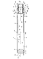
- FIG. 1 is a sectional view of the gas generator of the present invention in the direction of the axis X.
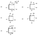
- FIG. 2 is a cross-sectional view of the cup-shaped member used in FIG. 1 in (a), and is a cross-sectional view of a cup-shaped member of another embodiment in (b) to (e).
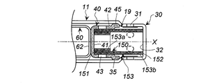
- FIG. 3 is a partial cross-sectional view in the axis X direction of a gas generator using a cylindrical filter different from that in FIG. 4A is a partial cross-sectional view in the direction of the axis X of a gas generator using a cup-shaped filter different from that in FIG. 1 in FIG. 4A, and FIG. It is a fragmentary sectional view of the direction of an axis X of a gas generator using.
- FIG. 5 is a partial cross-sectional view of an embodiment in which a diameter expansion prevention member is arranged in the gas generator shown in FIG. 1 in (a), and a diameter expansion prevention member different from (a) in (b) and (c). It is a fragmentary sectional view of an embodiment which arranged.
- US 6,474,685 B uses a lot of filters and members, so it has a complicated structure and is not suitable for weight reduction.
- the present invention provides a gas generator that is simple in structure and light in weight, and has improved cooling and filtering effects.
- the cylindrical housing used in the present invention is made of metal such as iron or stainless steel, and includes a cylindrical housing main body and a diffuser.
- the cylindrical housing main body portion and the diffuser portion may be joined by welding or may be integrally formed in advance.
- an electric igniter used in a known gas generator, or a combination of an electric igniter and a transfer charge can be used.
- an electric igniter used in a known gas generator or a combination of an electric igniter and a transfer charge
- an electric igniter used in a known gas generator or a combination of an electric igniter and a transfer charge
- an explosive charge a known gas generating agent or black explosive can be used.
- a plurality of gas discharge ports of the diffuser portion are formed on the peripheral wall portion of the cylindrical housing (diffuser portion), and are closed by a closing means such as a seal tape.
- a closing means such as a seal tape.
- the combustion chamber and the diffuser part are partitioned by a cup-shaped member.
- partitioned means that the combustion chamber space and the inner space of the diffuser portion are separated by a cup-shaped member, but a gas discharge path from the combustion chamber to the diffuser portion is secured.
- the gas discharge path from the combustion chamber to the diffuser section is a gas discharge path including the combustion chamber, the first gap, the communication hole, and the diffuser section.
- the cup-shaped member only needs to be arranged so that a first gap that communicates the combustion chamber and the diffuser portion is formed between the inner wall surface of the cylindrical housing main body portion.
- the cup-shaped member is fixed in the following form. can do.
- annular protrusion (annular step surface) protruding inward is formed between the cylindrical housing main body portion and the diffuser portion, and an opening end surface of the cup-shaped member is formed on the annular protrusion (annular step surface). Abutted form.
- an outer diameter of the turned-up portion and a cylindrical housing are used which has an enlarged-diameter portion in the opening and further has a turned-up portion from the enlarged diameter portion toward the bottom surface portion.
- turning part of the cup-shaped member was press-fitted with respect to the inner wall surface of a cylindrical housing by adjusting the internal diameter of.
- the outer diameter (d1) of the bottom surface and the outer diameter (d2) of the opening portion are d2> d1
- the peripheral wall portion from the bottom surface to the opening portion is an inclined surface, and further from the enlarged diameter portion to the bottom surface
- the outer part of the folded part and the inner diameter of the cylindrical housing are adjusted by using a part that has a folded part in the direction of the part, so that the folded part of the cup-shaped member is relative to the inner wall surface of the cylindrical housing. Press-fitted form.
- the combustion gas generated by the combustion of the gas generating agent in the combustion chamber passes through the combustion chamber, the first gap, and the communication hole to form a cylindrical filter. After passing through the first end face of the, it enters the diffuser section. Then, after passing near the second end face of the same cylindrical filter, it is discharged from the gas discharge port.
- the gas generator of the present invention that operates as described above can obtain the following effects (i) to (iii).
- the filter is a cylindrical filter, and the central axis of the cylindrical filter is arranged along the long axis direction of the cylindrical housing, when the combustion gas passes for the first time, When the combustion gas passes the second time near the first end face of the cylindrical filter, it passes near the second end face of the cylindrical filter. For this reason, compared with the embodiment of JP 2007-131254 A, combustion gas is easily discharged quickly.
- the peripheral wall portion of the cylindrical filter includes a thick portion on the first end surface side and a thin portion on the second end surface side, and only the thick portion is the What is facing the communicating hole of a cup-shaped member is preferable.
- Combustion gas generated by the combustion of the gas generating agent in the combustion chamber passes through the combustion chamber, the first gap, and the communication hole near the first end surface of the cylindrical filter and then enters the diffuser section. For this reason, the combustion gas passing near the first end face of the cylindrical filter always passes through the thick part of the cylindrical filter, and the cooling effect and the filtering effect are enhanced.
- the thickness ratio between the thick part and the thin part is not particularly limited, but for example, the thickness of the thick part / thickness of the thin part can be in the range of 1.2 to 3.0.
- the gas generator of the second embodiment is different from the gas generator of the first embodiment in that a cup-shaped filter is used as a filter.
- the communication hole of the cup-shaped member may be opposed to only the peripheral wall portion of the cup-shaped filter, or may be opposed to the bottom surface portion together with the peripheral wall portion of the cup-shaped filter.
- the gas generator of the second embodiment performs the same operation as the gas generator of the first embodiment, and the same effect is obtained.
- the thickness of the bottom surface portion of the cup-shaped filter is larger than the thickness of the peripheral wall portion of the cup-shaped filter and larger than the inner diameter of the communication hole of the cup-shaped member. It is preferable that only the bottom surface portion of the cup-shaped filter is opposed to the communication hole of the cup-shaped member.
- Combustion gas generated by combustion of the gas generating agent in the combustion chamber passes through the bottom surface of the cup-shaped filter from the combustion chamber, the first gap, and the communication hole, and then enters the diffuser portion.
- the combustion gas enters the diffuser part it passes through the bottom part of the cup-shaped filter that is thicker than the peripheral wall part, so that the cooling effect and the filtering effect are enhanced.
- the cup-shaped member has an outer diameter on the opening side larger than the outer diameter of the bottom surface part, An annular step surface is formed on the inner wall surface on the diffuser portion side of the cylindrical housing, Since the end surface of the opening of the cup-shaped member is in contact with the annular stepped surface, the first gap is formed between the peripheral wall portion having the communication hole of the cup-shaped member and the inner wall surface of the cylindrical housing main body portion. Formed, The outer surface of the peripheral wall portion on the first end face side of the cylindrical filter is in contact with the inner surface of the peripheral wall portion having the communication hole of the cup-shaped member, and the second end face side of the cylindrical filter is on the second end face side. It is preferable that a second gap is formed between the outer surface of the peripheral wall portion and the gas discharge port (third embodiment).
- the cup-shaped member has an outer diameter on the opening side larger than the outer diameter of the bottom surface part.
- An annular step surface is formed on the inner wall surface on the diffuser portion side of the cylindrical housing, Since the end surface of the opening of the cup-shaped member is in contact with the annular stepped surface, the first gap is formed between the peripheral wall portion having the communication hole of the cup-shaped member and the inner wall surface of the cylindrical housing main body portion.
- the outer surface of the peripheral wall portion on the bottom surface side of the cup-shaped filter is in contact with the inner surface of the peripheral wall portion having the communication hole of the cup-shaped member, and the peripheral wall portion on the opening side of the cup-shaped filter
- a second gap is preferably formed between the outer surface of the gas and the gas discharge port (fourth embodiment).
- the cup-shaped member has an outer diameter on the opening side larger than the outer diameter of the bottom surface.
- the cup-shaped member used in the above-described forms (II), (III), (V) and (VI) can be used.
- the annular step surface can be the annular protrusion in the form (I) and the annular step surface in the form (IV).
- the cup-shaped member and the annular stepped surface are the outer surfaces of the peripheral wall portion on the second end face side of the cylindrical filter when the cylindrical filter or the cup-shaped filter is disposed.
- the dimensions are adjusted so that a second gap is formed between the outer surface of the peripheral wall portion on the opening side of the cup-shaped filter and the gas discharge port.
- the cup-shaped member has an outer diameter on the opening side larger than the outer diameter of the bottom surface part,
- An annular step surface is formed on the inner wall surface on the diffuser portion side of the cylindrical housing, Since the end surface of the opening of the cup-shaped member is in contact with the annular stepped surface, the first gap is formed between the peripheral wall portion having the communication hole of the cup-shaped member and the inner wall surface of the cylindrical housing main body portion. Formed, The outer surface of the peripheral wall portion on the first end surface side of the cylindrical filter is in contact with the inner surface of the peripheral wall portion having the communication hole of the cup-shaped member, and the peripheral wall portion on the second end surface side of the cylindrical filter.
- a second gap is formed between the outer surface of the gas outlet and the gas outlet, The area (A1) where the peripheral wall portion of the cylindrical filter is in contact with the peripheral wall portion of the cup-shaped member, and the area (A2) where the peripheral wall portion of the cylindrical filter faces the second gap
- A2 is in the range of more than 50% to 80% when the total area of A1 and A2 is 100%.
- the cup-shaped member has a larger outer diameter on the opening side than the outer diameter of the bottom surface part,
- An annular step surface is formed on the inner wall surface on the diffuser portion side of the cylindrical housing, Since the end surface of the opening of the cup-shaped member is in contact with the annular stepped surface, the first gap is formed between the peripheral wall portion having the communication hole of the cup-shaped member and the inner wall surface of the cylindrical housing main body portion.
- a second gap is formed between the outer surface of the gas outlet and the gas outlet, The area (A1) where the peripheral wall of the cup-shaped filter is in contact with the peripheral wall of the cup-shaped member, and the area (A2) where the peripheral wall of the cup-shaped filter faces the second gap.
- A2 is in the range of more than 50% to 80% when the total area of A1 and A2 is 100%.
- the effects (i) and (iii) are particularly prominent.
- the area% of A2 is more preferably in the range of 60% to 80%, and further preferably in the range of 60 to 75%.
- the cup-shaped member has an outer diameter on the opening side larger than the outer diameter of the bottom surface part,
- An annular step surface is formed on the inner wall surface on the diffuser portion side of the cylindrical housing, Since the end surface of the opening of the cup-shaped member is in contact with the annular stepped surface, the first gap is formed between the peripheral wall portion having the communication hole of the cup-shaped member and the inner wall surface of the cylindrical housing main body portion. Formed, The outer surface of the peripheral wall portion on the first end face side of the cylindrical filter is in contact with the inner surface of the peripheral wall portion having the communication hole of the cup-shaped member, and the second end face side of the cylindrical filter is on the second end face side.
- a second gap is formed between the outer surface of the peripheral wall and the gas outlet, For preventing the peripheral wall portion on the second end face side of the tubular filter from expanding between the peripheral wall portion on the second end face side of the cylindrical filter and the inner peripheral wall surface on the closed end face side of the diffuser portion.
- the one in which the diameter expansion preventing member is arranged is preferable.
- the cup-shaped member has a larger outer diameter on the opening side than the outer diameter of the bottom surface part,
- An annular step surface is formed on the inner wall surface on the diffuser portion side of the cylindrical housing, Since the end surface of the opening of the cup-shaped member is in contact with the annular stepped surface, the first gap is formed between the peripheral wall portion having the communication hole of the cup-shaped member and the inner wall surface of the cylindrical housing main body portion.
- the outer surface of the peripheral wall portion on the bottom surface side of the cup-shaped filter is in contact with the inner surface of the peripheral wall portion having the communication hole of the cup-shaped member, and the peripheral wall portion on the opening side of the cup-shaped filter A second gap is formed between the outer surface of the gas outlet and the gas outlet, An enlargement for preventing the diameter of the peripheral wall portion on the opening side of the cup-shaped filter from expanding between the peripheral wall portion on the opening side of the cup-shaped filter and the inner peripheral wall surface on the closed end surface side of the diffuser portion.
- the one in which the diameter blocking member is disposed is preferable.
- the cylindrical filter or cup-shaped filter on the closed end face side of the diffuser section passes through the combustion gas May be deformed so as to expand outward in the radial direction under the pressure of.
- the filter is deformed so as to expand in the radial direction in this way, the second gap is reduced, and the cooling effect and the filtering effect may be reduced. Is prevented from occurring.
- the gas generator of the present invention has a simple structure and is lightweight, and has excellent combustion gas cooling effect and filtration effect.
- the gas generator of the present invention can be used as a gas generator for an airbag device mounted on an automobile.
- a gas generator 1 shown in FIG. 1 includes a cylindrical housing 10 which is an outer shell container, which includes a cylindrical housing body 11 and a diffuser 30. It is.
- the cylindrical housing body 11 and the diffuser 30 are made of metal such as stainless steel.
- An igniter 15 is attached to the first end 12 a side of the cylindrical housing body 11.
- the igniter 15 has an igniter main body portion having an ignition portion 16 fixed to an igniter collar 17.
- a well-known explosive can be used together as needed.
- an O-ring 18 for moisture prevention is disposed between the igniter collar 17 and the inner wall surface 11a of the cylindrical housing main body 11.
- the first end 12 a of the cylindrical housing main body 11 and the second end 12 b opposite to the axis X direction are closed by a diffuser 30 having a gas discharge port 31.
- the diffuser part 30 has a closed end face 32 and a peripheral wall part 33.
- the cylindrical housing body 11 and the diffuser 30 are welded at a welded portion 19.
- a plurality of gas discharge ports 31 are formed at equal intervals in the circumferential direction, and are closed with an aluminum seal tape 34 from the inside.
- annular step surface 35 is formed at the boundary between the cylindrical housing body 11 and the diffuser 30.
- the annular step surface 35 is formed by setting the inner diameter (D1) of the cylindrical housing body 11 and the inner diameter (D2) of the diffuser part 30 to D1> D2.
- D1 and D2 are the first end 12a side inner diameter and the second end respectively in contact with the annular step.
- the inner diameter is the portion 12b side. That is, when the inner diameters are not constant, for example, in FIG. 1, D1 is the inner diameter of the portion of the housing main body adjacent to the left side of the annular step surface 35, and D2 is the portion of the diffuser portion 30 adjacent to the right side of the annular step surface 35. Of the inner diameter.
- the internal space of the cylindrical housing body 11 is a combustion chamber 20 containing a gas generating agent 21.
- a retainer for adjusting the volume of the combustion chamber 20 according to the filling amount of the gas generating agent 21 may be disposed in the combustion chamber 20 as necessary.
- the combustion chamber 20 and the diffuser part 30 are partitioned by a cup-shaped member 40.
- the cup-shaped member 40 is made of iron, stainless steel, or the like, and has a bottom surface portion 41, a peripheral wall portion 42 in which a communication hole 43 is formed, and an opening portion 44, as shown in FIGS. It is what you are doing.
- a plurality of communication holes 43 are formed at equal intervals in the circumferential direction.
- the end surface on the opening 44 side of the cup-shaped member 40 has a diameter-expanded portion 45 that expands outward.
- the enlarged diameter portion 45 includes an annular enlarged diameter portion 45 a that extends in the same direction as the peripheral wall portion 42, and an annular inclined surface portion 45 b that exists between the annular enlarged diameter portion 45 a and the peripheral wall portion 42.
- the outer diameter of the annular enlarged portion 45 a is larger than the outer diameter of the peripheral wall portion 42.
- the cup-shaped member 40 can be press-fitted into the housing main body 11 by adjusting the outer diameter of the enlarged diameter portion 45 and the inner diameter of the cylindrical housing main body 11.
- the shape of the cup-shaped member 40 can be used in various forms by relating to the shapes of the cylindrical housing body 11 and the diffuser 30.
- FIG. 2 (b) shows that a portion corresponding to the enlarged diameter portion 45 of FIG. 2 (a) is a normal flange portion 46.
- FIG. 2 (c) is the one without the enlarged diameter portion 45 of FIG. 2 (a).
- the outer diameter (d1) of the bottom surface portion 41 and the outer diameter (d2) of the opening portion 44 are d2> d1
- the peripheral wall portion 42a from the bottom surface portion 41 to the opening portion 44 is an inclined surface. It is what.
- FIG. 2 (e) has a folded portion 47 from the flange portion 46 toward the bottom surface portion 41 in addition to the flange portion 46 of FIG. 2 (b).
- the bottom surface portion 41 is positioned on the first end portion 12 a side, and the annular diameter-expanded portion 45 a of the diameter-expanded portion 45 of the opening 44 is formed. It is in contact with the annular step surface 35. For this reason, a first gap 25 is formed between the inner wall surface 11 a and the peripheral wall portion 42 of the cylindrical housing main body portion 11 facing outward in the radial direction.
- the width of the first gap 25 is a size corresponding to the difference between the outer diameter of the peripheral wall portion 42 and the annular enlarged diameter portion 45 a of the enlarged diameter portion 45.
- the combustion chamber 20 and the diffuser portion 30 are communicated with each other through the communication hole 43 through the first gap 25.
- a cylindrical filter 50 is disposed in a space surrounded by the cup-shaped member 40 and the diffuser part 30.
- the cylindrical filter 50 has a first end surface 51 in contact with the bottom surface portion 41 of the cup-shaped member 40, and a second end surface 52 opposite to the axis X direction in contact with the closed end surface 32 of the diffuser portion 30.
- the outer peripheral surface 53 a of the peripheral wall portion 53 on the first end surface 51 side is in contact with the inner wall surface 42 a of the peripheral wall portion 42 of the cup-shaped member 40, and the remaining peripheral wall portion 53 on the second end surface 52 side.
- a second gap 37 is formed between the outer peripheral surface 53a of the gas generator and the peripheral wall portion 33 where the gas discharge port 31 of the diffuser portion 30 is located.
- the cylindrical filter 50 is arranged so that the central axis of the cylindrical filter 50 is in a direction along the axis X of the cylindrical housing 10.
- the communication hole 43 of the cup-shaped member 40 is formed near the first end surface 51 of the cylindrical filter 50 and at a position facing the first gap 25.
- the gas discharge port 31 of the diffuser unit 30 is formed near the second end surface 52 of the cylindrical filter 50.
- A2 is about 70%.
- a cylindrical support member 60 that is further opened on the first end 12a side and closed on the second end 12b side is disposed.
- the cylindrical support member 60 is used to form a filling space for accommodating the gas generating agent on the inside and to support the cup-shaped member 40 and the cylindrical filter 50 in the axis X direction. If 40 is fixed, it may not be used.
- the filling space is also included in the combustion chamber.
- the cylindrical support member 60 is made of a metal such as stainless steel.
- the cylindrical support member 60 has an outer diameter smaller than the inner diameter of the cylindrical housing main body 11, and a cylindrical gap 65 is formed between the cylindrical support member 60 and the cylindrical housing main body 11. Yes.
- a plurality of gas passage holes 63 are formed in the peripheral wall portion 61 at equal intervals in the axial direction and the circumferential direction. The filling chamber and the cylindrical gap 65 are communicated with each other through a gas passage hole 63.
- the cylindrical support member 60 has an enlarged diameter portion 66 at an opening on the igniter 15 side, and an outer peripheral edge portion 66 a of the enlarged diameter portion 66 is in contact with the inner wall surface 11 a of the cylindrical housing body 11.
- the closed end face 62 is in contact with the bottom face portion 41 of the cup-shaped member 40.
- the outer peripheral edge 66 a has an outer diameter slightly larger than the inner diameter of the cylindrical housing body 11, and when disposed in the cylindrical housing body 11, the outer diameter 66 a is cylindrical due to the elasticity of the enlarged diameter portion 66.
- the housing body 11 is press-fitted into the inner wall surface 11 a. When the enlarged diameter portion 66 is formed in an annular shape, no gap is formed in the press-fitted portion.
- the gas generator 1 of the present invention can be replaced with the cylindrical filter 50 shown in FIG. 1 and a cylindrical filter 150 shown in FIG.
- the cylindrical filter 150 includes a first end surface 151, a second end surface 152, and a peripheral wall portion 153.
- the peripheral wall portion 153 includes a thick portion 153a on the first end surface 152 side and a thin portion 153b on the second end surface 152 side. It consists of
- An annular step surface is formed between the thick portion 153a and the thin portion 153b, but an inclined surface inclined from the thick portion 153a toward the thin portion 153b may be used.
- the communication hole 43 of the cup-shaped member 40 is opposed only to the thick portion 153a.
- the cylindrical filter 150 may be such that the thickness of the peripheral wall portion 153 decreases from the first end surface 151 to the second end surface 152.
- the igniter 15 is activated and the gas generating agent 21 in the combustion chamber 20 is ignited and combusted to generate combustion gas.
- the combustion gas flows in the direction of the second end portion 12b through the gas passage hole 63 of the cylindrical support member 60 while entering and exiting between the cylindrical gap 65 and the filling space.
- the first gap 25 is reached, and from there through the communication hole 43 and the first end face 51 of the cylindrical filter 50, enters the diffuser portion 30, passes through the cylindrical filter 50 again, and enters the second gap 37. enter.
- the outer surface of the peripheral wall portion 53 on the first end surface 51 side of the tubular filter 50 is in contact with the inner wall surface 42 a of the peripheral wall portion 42 having the communication hole 43 of the cup-shaped member 40. For this reason, almost the entire amount of the gas that has passed through the communication hole 43 enters the space inside the cylindrical filter 50.
- the combustion gas passes through the peripheral wall 53 on the second end 52 side of the cylindrical filter 50, breaks the seal tape 34, and is discharged from the gas discharge port 31.
- the cooling effect and the filtration effect can be enhanced as compared with the case where the combustion gas passes through the filter only once.
- the central axis of the cylindrical filter 50 is disposed along the axis X direction of the cylindrical housing 11, when the combustion gas passes for the first time, it passes near the first end face 51 of the cylindrical filter 50. When the combustion gas passes for the second time, it passes through the second end face 52 of the cylindrical filter 50. Therefore, the internal space of the cylindrical filter 50 functions as a residue collection space, and gas clogging due to clogging of the residue is less likely to occur and the output performance is stabilized as compared with a cylindrical filter that is clogged up to the inside. Further, the second gap 37 makes it easy for combustion gas to pass through a wide area of the cylindrical filter 50. This effect can be further enhanced by adjusting the range of A2 / (A1 + A2) ⁇ 100.
- Gas generator 1A, 1B of 2nd Embodiment is demonstrated with reference to Fig.4 (a), (b).
- the gas generators 1A and 1B shown in FIGS. 4A and 4B are the same as the gas generator 1 of FIG. 1 except that the shape of the filter is different.
- the bottom surface portion 251 is in contact with the bottom surface portion 41 of the cup-shaped member 40, and the end surface of the opening 253 of the cup-shaped filter 250 is in contact with the closed end surface 32 of the diffuser portion 30.
- the communication hole 43 of the cup-shaped member 40 is formed at a position near the bottom surface portion 251 of the cup-shaped filter 250 and facing the first gap 25, and the gas discharge port 31 of the diffuser section 30 is an opening of the cup-shaped filter 250. It is formed closer to the part 253.
- the cup-shaped filter 250 increases in mass by the bottom surface portion 251, but the portion of the bottom surface portion 251 facing the diffuser portion 30. Becomes uneven, and the surface area increases, so the combustion residue capturing effect is enhanced.
- the cup-shaped filter 350 shown in FIG. 4B has a bottom surface portion 351, a peripheral wall portion 352, and an opening 353.
- the thickness of the bottom surface portion 351 is larger than the thickness of the peripheral wall portion 352, and the cup-shaped member 40 is used. It is larger than the inner diameter of the communication hole 43.
- the bottom surface portion 351 is in contact with the bottom surface portion 41 of the cup-shaped member 40, and the end surface of the opening 353 of the cup-shaped filter 350 is in contact with the closed end surface 32 of the diffuser portion 30.
- the cup-shaped filter 350 is opposed so that the middle position of the thickness of the bottom surface portion 351 coincides with the center of the communication hole 43 of the cup-shaped member 40. For this reason, all of the communication holes 43 face the bottom surface portion 351, and the combustion gas that has entered from the communication holes 42 always passes through the bottom surface portion 351 of the cup-shaped filter 350 in the radial direction, thereby providing a cooling effect. And the filtration effect is enhanced.
- Gas generators 1C, 1D, and 1E according to other embodiments will be described.
- Gas generators 1C, 1D, and 1E shown in FIGS. 5A to 5C are the same as the gas generator 1 shown in FIG. 1 except that the diameter expansion prevention member of the cylindrical filter 50 is disposed.
- the cylindrical filter shown in FIG. 3 is replaced with the cup shown in FIGS. 4A and 4B instead of the cylindrical filter 50.
- a filter can also be used.
- the gas generator 1C of the embodiment of FIG. 5A has an annular expansion between the peripheral wall portion 53 on the second end surface 52 side of the cylindrical filter 50 and the inner peripheral wall surface 30a on the closed end surface 32 side of the diffuser portion 30.
- a diameter blocking member 70 is disposed.
- the annular expansion preventing member 70 has an inner peripheral surface in contact with the peripheral wall portion 53 of the cylindrical filter 50, and from the viewpoint of avoiding interference with the seal tape 34, the outer peripheral surface thereof is the peripheral wall portion 33 of the diffuser portion. Are opposed to each other with a slight gap.
- the gas generator 1D of the embodiment of FIG. 5B has a shallow bottom between the peripheral wall portion 53 on the second end surface 52 side of the cylindrical filter 50 and the inner peripheral wall surface 30a on the closed end surface 32 side of the diffuser portion 30.
- a cup-shaped expansion preventing member 80 is disposed.
- the cup-shaped diameter expansion prevention member 80 has a bottom surface portion 81 and a peripheral wall portion 82.
- the bottom surface portion 81 of the cup-shaped expansion preventing member 80 is in contact with the closed end surface 32 of the diffuser portion 30, and the inner peripheral surface of the peripheral wall portion 82 is in contact with the peripheral wall portion 53 of the tubular filter 50. From the viewpoint of avoiding interference with the tape 34, the outer peripheral surface of the peripheral wall portion 82 is opposed to the peripheral wall portion 33 of the diffuser portion with a slight gap.
- the gas generator 1E of the embodiment of FIG. 5C includes a plurality of independent protrusions between the peripheral wall portion 53 on the second end surface 52 side of the cylindrical filter 50 and the peripheral wall portion on the closed end surface 32 side of the diffuser portion 30.
- the diameter expansion preventing member 90 is arranged.
- the diameter-increasing prevention member 90 made up of a plurality of independent protrusions protrudes inward from the peripheral wall portion 33 of the diffuser portion.
- a plurality (for example, 2 to 8) are formed at equal intervals in the circumferential direction and are not in contact with the seal tape 34.
- the diameter expansion preventing member 90 made up of a plurality of independent protrusions is in contact with the peripheral wall portion 53 on the second end face 52 side of the cylindrical filter 50 or opposed with a slight gap.
- the diameter expansion preventing member 90 may be a continuous annular protrusion other than the plurality of independent protrusions.
- the flange integrally formed in the 2nd end surface 52 side of the cylindrical filter 50 may be sufficient.
- the gas generators 1C, 1D, and 1E shown in FIGS. 5A to 5C operate as follows due to the arrangement of the diameter expanding members 70, 80, and 90.
- the combustion gas that has entered the diffuser portion 30 through the tubular filter 50 from the communication hole 43 of the cup-shaped member 40 passes through the tubular filter 50 again as described in the operation mechanism of the gas generator in FIG. After entering the two gaps 37, the seal tape 34 is broken and the gas is discharged from the gas outlet 31.
- the second end face 52 side of the cylindrical filter 50 receives the pressure when the combustion gas passes to expand outward in the radial direction. In some cases, the second gap 37 may be reduced. However, since the gas generators 1C, 1D, and 1E shown in FIGS. 5A to 5C are provided with the diameter-expanding members 70, 80, and 90, the second end face 52 side of the tubular filter 50 is radially outward. The deformation so as to expand is prevented, and the second gap 37 is not reduced. For this reason, the cooling effect and filtration effect by the cylindrical filter 50 are fully exhibited.
Landscapes
- Engineering & Computer Science (AREA)
- Mechanical Engineering (AREA)
- Chemical & Material Sciences (AREA)
- Physics & Mathematics (AREA)
- Fluid Mechanics (AREA)
- Organic Chemistry (AREA)
- Chemical Kinetics & Catalysis (AREA)
- Air Bags (AREA)
- Feeding, Discharge, Calcimining, Fusing, And Gas-Generation Devices (AREA)
- Filtering Of Dispersed Particles In Gases (AREA)
Abstract
Description
ガス発生源としてガス発生剤を含むガス発生器には、燃焼ガスを濾過および冷却するためのフィルタを備えているものがある。
本発明の第1実施形態(以下、「第1実施形態」という)は、筒状ハウジング本体部とディフューザ部からなる筒状ハウジングを有しており、
前記筒状ハウジング本体部の第1端部側に点火手段を有し、前記第1端部とは軸方向反対側の第2端部側がガス排出口を有するディフューザ部により閉塞されており、
前記筒状ハウジング本体部の内部空間にガス発生剤を含む燃焼室が存在し、
前記燃焼室と前記ディフューザ部との間がカップ状部材により仕切られており、
前記カップ状部材が、底面部、連通孔が形成された周壁部、および開口部を有しており、前記底面部が筒状ハウジングの第1端部側に位置し、前記開口部が第2端部側に位置し、前記周壁部が、半径方向外側に対向している前記筒状ハウジング本体部の内壁面との間に、前記燃焼室と前記ディフューザ部を連絡する第1間隙が形成されるように配置されているものであり、
さらに前記カップ状部材と前記ディフューザ部で囲まれた空間内に筒状フィルタが配置されており、
前記筒状フィルタが、第1端面が前記カップ状部材の底面部に当接され、反対側の第2端面が前記ディフューザ部の閉塞端面に当接されて、前記筒状フィルタの中心軸が前記筒状ハウジングの長軸方向に沿って配置されているものであり、
前記カップ状部材の連通孔が、前記筒状フィルタの第1端面寄りで、かつ前記第1間隙に面した位置に形成され、前記ディフューザ部のガス排出口が、前記筒状フィルタの第2端面寄りに形成されているものである、ガス発生器である。
前記筒状ハウジング本体部の第1端部側に点火手段を有し、前記第1端部とは軸方向反対側の第2端部側がガス排出口を有するディフューザ部により閉塞されており、
前記筒状ハウジング本体部の内部空間にガス発生剤を含む燃焼室が存在し、
前記燃焼室と前記ディフューザ部との間がカップ状部材により仕切られており、
前記カップ状部材が、底面部、連通孔が形成された周壁部、および開口部を有しており、前記底面部が筒状ハウジングの第1端部側に位置し、前記開口部が第2端部側に位置し、前記周壁部が、半径方向外側に対向している前記筒状ハウジング本体部の内壁面との間に、前記燃焼室と前記ディフューザ部を連絡する第1間隙が形成されるように配置されているものであり、
さらに前記カップ状部材と前記ディフューザ部で囲まれた空間内に、底面部、周壁部および開口部を有するカップ状フィルタが配置されており、
前記カップ状フィルタが、前記カップ状フィルタの底面部が前記カップ状部材の底面部に当接され、前記カップ状フィルタの開口部の端面が前記ディフューザ部の閉塞端面に当接されて、前記カップ状フィルタの中心軸が前記筒状ハウジングの長軸方向に沿って配置されているものであり、
前記カップ状部材の連通孔が、前記カップ状フィルタの底面部寄りで、かつ前記第1間隙に面した位置に形成され、前記ディフューザ部のガス排出口が、前記カップ状フィルタの開口部寄りに形成されているものである、ガス発生器である。
JP 2014-184427 Aのガス発生器はハイブリッド型式であるため、破裂板(第2破裂板)58が必要であり、加圧ガス室ハウジング内にフィルタを配置するときには、上記のようなフィルタの保持構造が必要となる。そのための構造が複雑となり、簡素化という点で改良の余地を残している。
前記筒状ハウジングの前記ディフューザ部側の内壁面には、環状段差面が形成されており、
前記カップ状部材の開口部端面が前記環状段差面に当接されることで、前記カップ状部材の連通孔を有する周壁部と前記筒状ハウジング本体部の内壁面の間に前記第1間隙が形成されており、
前記カップ状部材の連通孔を有する周壁部の内表面に対して、前記筒状フィルタの第1端面側の周壁部の外表面が当接されており、前記筒状フィルタの第2端面側の周壁部の外表面と、前記ガス排出口の間に第2間隙が形成されているもの(第3実施形態)が好ましい。
前記筒状ハウジングの前記ディフューザ部側の内壁面には、環状段差面が形成されており、
前記カップ状部材の開口部端面が前記環状段差面に当接されることで、前記カップ状部材の連通孔を有する周壁部と前記筒状ハウジング本体部の内壁面の間に前記第1間隙が形成されており、
前記カップ状部材の連通孔を有する周壁部の内表面に対して、前記カップ状フィルタの底面部側の周壁部の外表面が当接されており、前記カップ状フィルタの開口部側の周壁部の外表面と、前記ガス排出口の間に第2間隙が形成されているもの(第4実施形態)が好ましい。
前記筒状ハウジングの前記ディフューザ部側の内壁面には、環状段差面が形成されており、
前記カップ状部材の開口部端面が前記環状段差面に当接されることで、前記カップ状部材の連通孔を有する周壁部と前記筒状ハウジング本体部の内壁面の間に前記第1間隙が形成されており、
前記カップ状部材の連通孔を有する周壁部の内表面に対して、前記筒状フィルタの第1端面側の周壁部の外表面が当接され、前記筒状フィルタの第2端面側の周壁部の外表面と、前記ガス排出口の間に第2間隙が形成されており、
前記筒状フィルタの周壁部と、前記カップ状部材の周壁部が当接されている面積(A1)と、前記前記筒状フィルタの周壁部が、前記第2間隙に面している面積(A2)が、A1とA2の合計面積を100%とするときのA2が50%超~80%の範囲であるものが好ましい。
前記筒状ハウジングの前記ディフューザ部側の内壁面には、環状段差面が形成されており、
前記カップ状部材の開口部端面が前記環状段差面に当接されることで、前記カップ状部材の連通孔を有する周壁部と前記筒状ハウジング本体部の内壁面の間に前記第1間隙が形成されており、
前記カップ状部材の連通孔を有する周壁部の内表面に対して、前記カップ状フィルタの底面部側の周壁部の外表面が当接されており、前記カップ状フィルタの開口部側の周壁部の外表面と、前記ガス排出口の間に第2間隙が形成されており、
前記カップ状フィルタの周壁部と、前記カップ状部材の周壁部が当接されている面積(A1)と、前記カップ状フィルタの周壁部が、前記第2間隙に面している面積(A2)が、A1とA2の合計面積を100%とするときのA2が50%超~80%の範囲であるものが好ましい。
前記筒状ハウジングの前記ディフューザ部側の内壁面には、環状段差面が形成されており、
前記カップ状部材の開口部端面が前記環状段差面に当接されることで、前記カップ状部材の連通孔を有する周壁部と前記筒状ハウジング本体部の内壁面の間に前記第1間隙が形成されており、
前記カップ状部材の連通孔を有する周壁部の内表面に対して、前記筒状フィルタの第1端面側の周壁部の外表面が当接されており、前記筒状フィルタの第2端面側の周壁部の外表面と、前記ガス排出口の間に第2間隙が形成されており、
前記筒状フィルタの第2端面側の周壁部と、前記ディフューザ部の閉塞端面側の内周壁面の間に、前記筒状フィルタ第2端面側の周壁部が拡径することを阻止するための拡径阻止部材が配置されているものが好ましい。
前記筒状ハウジングの前記ディフューザ部側の内壁面には、環状段差面が形成されており、
前記カップ状部材の開口部端面が前記環状段差面に当接されることで、前記カップ状部材の連通孔を有する周壁部と前記筒状ハウジング本体部の内壁面の間に前記第1間隙が形成されており、
前記カップ状部材の連通孔を有する周壁部の内表面に対して、前記カップ状フィルタの底面部側の周壁部の外表面が当接されており、前記カップ状フィルタの開口部側の周壁部の外表面と、前記ガス排出口の間に第2間隙が形成されており、
前記カップ状フィルタの開口部側の周壁部と、前記ディフューザ部の閉塞端面側の内周壁面の間に、前記カップ状フィルタの開口部側の周壁部が拡径することを阻止するための拡径阻止部材が配置されているものが好ましい。
(1)第1実施形態のガス発生器
図1に示すガス発生器1は、外殻容器である筒状ハウジング10が筒状ハウジング本体部11とディフューザ部30からなるものである。筒状ハウジング本体部11とディフューザ部30は、ステンレスなどの金属製である。
図4(a)、(b)により第2実施形態のガス発生器1A、1Bを説明する。図4(a)、(b)に示すガス発生器1A、1Bは、図1のガス発生器1とはフィルタの形状が異なるほかは同じものである。
Claims (10)
- 筒状ハウジング本体部とディフューザ部からなる筒状ハウジングを有しており、
前記筒状ハウジング本体部の第1端部側に点火手段を有し、前記第1端部とは軸方向反対側の第2端部側がガス排出口を有するディフューザ部により閉塞されており、
前記筒状ハウジング本体部の内部空間にガス発生剤を含む燃焼室が存在し、
前記燃焼室と前記ディフューザ部との間がカップ状部材により仕切られており、
前記カップ状部材が、底面部、連通孔が形成された周壁部、および開口部を有しており、前記底面部が筒状ハウジングの第1端部側に位置し、前記開口部が第2端部側に位置し、前記周壁部が、半径方向外側に対向している前記筒状ハウジング本体部の内壁面との間に、前記燃焼室と前記ディフューザ部を連絡する第1間隙が形成されるように配置されているものであり、
さらに前記カップ状部材と前記ディフューザ部で囲まれた空間内に筒状フィルタが配置されており、
前記筒状フィルタが、第1端面が前記カップ状部材の底面部に当接され、反対側の第2端面が前記ディフューザ部の閉塞端面に当接されて、前記筒状フィルタの中心軸が前記筒状ハウジングの長軸方向に沿って配置されているものであり、
前記カップ状部材の連通孔が、前記筒状フィルタの第1端面寄りで、かつ前記第1間隙に面した位置に形成され、前記ディフューザ部のガス排出口が、前記筒状フィルタの第2端面寄りに形成されているものである、ガス発生器。 - 前記筒状フィルタの周壁部が、前記第1端面側の肉厚部と前記第2端面側の肉薄部からなるものであり、前記肉厚部のみが前記カップ状部材の連通孔に対向されている、請求項1記載のガス発生器。
- 筒状ハウジング本体部とディフューザ部からなる筒状ハウジングを有しており、
前記筒状ハウジング本体部の第1端部側に点火手段を有し、前記第1端部とは軸方向反対側の第2端部側がガス排出口を有するディフューザ部により閉塞されており、
前記筒状ハウジング本体部の内部空間にガス発生剤を含む燃焼室が存在し、
前記燃焼室と前記ディフューザ部との間がカップ状部材により仕切られており、
前記カップ状部材が、底面部、連通孔が形成された周壁部、および開口部を有しており、前記底面部が筒状ハウジングの第1端部側に位置し、前記開口部が第2端部側に位置し、前記周壁部が、半径方向外側に対向している前記筒状ハウジング本体部の内壁面との間に、前記燃焼室と前記ディフューザ部を連絡する第1間隙が形成されるように配置されているものであり、
さらに前記カップ状部材と前記ディフューザ部で囲まれた空間内に、底面部、周壁部および開口部を有するカップ状フィルタが配置されており、
前記カップ状フィルタが、前記カップ状フィルタの底面部が前記カップ状部材の底面部に当接され、前記カップ状フィルタの開口部の端面が前記ディフューザ部の閉塞端面に当接されて、前記カップ状フィルタの中心軸が前記筒状ハウジングの長軸方向に沿って配置されているものであり、
前記カップ状部材の連通孔が、前記カップ状フィルタの底面部寄りで、かつ前記第1間隙に面した位置に形成され、前記ディフューザ部のガス排出口が、前記カップ状フィルタの開口部寄りに形成されているものである、ガス発生器。 - 前記カップ状フィルタの底面部の厚みが、前記カップ状フィルタの周壁部の厚みよりも大きく、かつ前記カップ状部材の連通孔の内径よりも大きくなっており、
前記カップ状フィルタの底面部のみが前記カップ状部材の連通孔に対向されている、請求項3記載のガス発生器。 - 前記カップ状部材が、前記底面部の外径よりも前記開口部側の外径が大きくなっているものであり、
前記筒状ハウジングの前記ディフューザ部側の内壁面には、環状段差面が形成されており、
前記カップ状部材の開口部端面が前記環状段差面に当接されることで、前記カップ状部材の連通孔を有する周壁部と前記筒状ハウジング本体部の内壁面の間に前記第1間隙が形成されており、
前記カップ状部材の連通孔を有する周壁部の内表面に対して、前記筒状フィルタの第1端面側の周壁部の外表面が当接されており、前記筒状フィルタの第2端面側の周壁部の外表面と、前記ガス排出口の間に第2間隙が形成されている、請求項1記載のガス発生器。 - 前記カップ状部材が、前記底面部の外径よりも前記開口部側の外径が大きくなっているものであり、
前記筒状ハウジングの前記ディフューザ部側の内壁面には、環状段差面が形成されており、
前記カップ状部材の開口部端面が前記環状段差面に当接されることで、前記カップ状部材の連通孔を有する周壁部と前記筒状ハウジング本体部の内壁面の間に前記第1間隙が形成されており、
前記カップ状部材の連通孔を有する周壁部の内表面に対して、前記カップ状フィルタの底面部側の周壁部の外表面が当接されており、前記カップ状フィルタの開口部側の周壁部の外表面と、前記ガス排出口の間に第2間隙が形成されている、請求項3記載のガス発生器。 - 前記カップ状部材が、前記底面部の外径よりも前記開口部側の外径が大きくなっているものであり、
前記筒状ハウジングの前記ディフューザ部側の内壁面には、環状段差面が形成されており、
前記カップ状部材の開口部端面が前記環状段差面に当接されることで、前記カップ状部材の連通孔を有する周壁部と前記筒状ハウジング本体部の内壁面の間に前記第1間隙が形成されており、
前記カップ状部材の連通孔を有する周壁部の内表面に対して、前記筒状フィルタの第1端面側の周壁部の外表面が当接され、前記筒状フィルタの第2端面側の周壁部の外表面と、前記ガス排出口の間に第2間隙が形成されており、
前記筒状フィルタの周壁部と、前記カップ状部材の周壁部が当接されている面積(A1)と、前記前記筒状フィルタの周壁部が、前記第2間隙に面している面積(A2)が、A1とA2の合計面積を100%とするときのA2が50%超~80%の範囲である、請求項5記載のガス発生器。 - 前記カップ状部材が、前記底面部の外径よりも前記開口部側の外径が大きくなっているものであり、
前記筒状ハウジングの前記ディフューザ部側の内壁面には、環状段差面が形成されており、
前記カップ状部材の開口部端面が前記環状段差面に当接されることで、前記カップ状部材の連通孔を有する周壁部と前記筒状ハウジング本体部の内壁面の間に前記第1間隙が形成されており、
前記カップ状部材の連通孔を有する周壁部の内表面に対して、前記カップ状フィルタの底面部側の周壁部の外表面が当接されており、前記カップ状フィルタの開口部側の周壁部の外表面と、前記ガス排出口の間に第2間隙が形成されており、
前記カップ状フィルタの周壁部と、前記カップ状部材の周壁部が当接されている面積(A1)と、前記カップ状フィルタの周壁部が、前記第2間隙に面している面積(A2)が、A1とA2の合計面積を100%とするときのA2が50%超~80%の範囲である、請求項6記載のガス発生器。 - 前記カップ状部材が、前記底面部の外径よりも前記開口部側の外径が大きくなっているものであり、
前記筒状ハウジングの前記ディフューザ部側の内壁面には、環状段差面が形成されており、
前記カップ状部材の開口部端面が前記環状段差面に当接されることで、前記カップ状部材の連通孔を有する周壁部と前記筒状ハウジング本体部の内壁面の間に前記第1間隙が形成されており、
前記カップ状部材の連通孔を有する周壁部の内表面に対して、前記筒状フィルタの第1端面側の周壁部の外表面が当接されており、前記筒状フィルタの第2端面側の周壁部の外表面と、前記ガス排出口の間に第2間隙が形成されており、
前記筒状フィルタの第2端面側の周壁部と、前記ディフューザ部の閉塞端面側の内周壁面の間に、前記筒状フィルタ第2端面側の周壁部が拡径することを阻止するための拡径阻止部材が配置されている、請求項5記載のガス発生器。 - 前記カップ状部材が、前記底面部の外径よりも前記開口部側の外径が大きくなっているものであり、
前記筒状ハウジングの前記ディフューザ部側の内壁面には、環状段差面が形成されており、
前記カップ状部材の開口部端面が前記環状段差面に当接されることで、前記カップ状部材の連通孔を有する周壁部と前記筒状ハウジング本体部の内壁面の間に前記第1間隙が形成されており、
前記カップ状部材の連通孔を有する周壁部の内表面に対して、前記カップ状フィルタの底面部側の周壁部の外表面が当接されており、前記カップ状フィルタの開口部側の周壁部の外表面と、前記ガス排出口の間に第2間隙が形成されており、
前記カップ状フィルタの開口部側の周壁部と、前記ディフューザ部の閉塞端面側の内周壁面の間に、前記カップ状フィルタの開口部側の周壁部が拡径することを阻止するための拡径阻止部材が配置されている、請求項6記載のガス発生器。
Priority Applications (4)
| Application Number | Priority Date | Filing Date | Title |
|---|---|---|---|
| CN201780030397.0A CN109257930B (zh) | 2016-05-23 | 2017-04-28 | 气体发生器 |
| KR1020187031030A KR102198476B1 (ko) | 2016-05-23 | 2017-04-28 | 가스 발생기 |
| US16/096,047 US10696267B2 (en) | 2016-05-23 | 2017-04-28 | Gas generator |
| DE112017002619.9T DE112017002619B4 (de) | 2016-05-23 | 2017-04-28 | Gas-Generator |
Applications Claiming Priority (2)
| Application Number | Priority Date | Filing Date | Title |
|---|---|---|---|
| JP2016-102061 | 2016-05-23 | ||
| JP2016102061A JP6619293B2 (ja) | 2016-05-23 | 2016-05-23 | ガス発生器 |
Publications (1)
| Publication Number | Publication Date |
|---|---|
| WO2017203934A1 true WO2017203934A1 (ja) | 2017-11-30 |
Family
ID=60412241
Family Applications (1)
| Application Number | Title | Priority Date | Filing Date |
|---|---|---|---|
| PCT/JP2017/016926 Ceased WO2017203934A1 (ja) | 2016-05-23 | 2017-04-28 | ガス発生器 |
Country Status (6)
| Country | Link |
|---|---|
| US (1) | US10696267B2 (ja) |
| JP (1) | JP6619293B2 (ja) |
| KR (1) | KR102198476B1 (ja) |
| CN (1) | CN109257930B (ja) |
| DE (1) | DE112017002619B4 (ja) |
| WO (1) | WO2017203934A1 (ja) |
Families Citing this family (6)
| Publication number | Priority date | Publication date | Assignee | Title |
|---|---|---|---|---|
| JP6633985B2 (ja) * | 2016-07-20 | 2020-01-22 | 株式会社ダイセル | ガス発生器 |
| JP6650365B2 (ja) * | 2016-07-26 | 2020-02-19 | 株式会社ダイセル | ガス発生器 |
| JP6934372B2 (ja) * | 2017-09-05 | 2021-09-15 | 株式会社ダイセル | ガス発生器 |
| JP7641169B2 (ja) * | 2021-04-30 | 2025-03-06 | 株式会社ダイセル | ガス発生器 |
| JP7808458B2 (ja) * | 2021-11-12 | 2026-01-29 | 株式会社ダイセル | ガス発生器用フィルタユニット、ガス発生器、及びガス発生器の製造方法 |
| JP2025142850A (ja) * | 2024-03-18 | 2025-10-01 | 日本化薬株式会社 | ガス発生器およびその製造方法 |
Citations (5)
| Publication number | Priority date | Publication date | Assignee | Title |
|---|---|---|---|---|
| JP2007302230A (ja) * | 2006-04-21 | 2007-11-22 | Tk Holdings Inc | ガス生成システム |
| US20080264022A1 (en) * | 2007-02-05 | 2008-10-30 | Trw Airbag Systems Gmbh | Filter for use in a gas generator |
| JP2010264773A (ja) * | 2009-05-12 | 2010-11-25 | Daicel Chem Ind Ltd | ガス発生器 |
| JP2010540336A (ja) * | 2007-10-05 | 2010-12-24 | タカタ・ペトリ アーゲー | ガス発生器及びガス発生器のガス流に影響を及ぼす方法 |
| JP2011157025A (ja) * | 2010-02-03 | 2011-08-18 | Daicel Chemical Industries Ltd | ガス発生器 |
Family Cites Families (37)
| Publication number | Priority date | Publication date | Assignee | Title |
|---|---|---|---|---|
| US5350190A (en) * | 1993-07-06 | 1994-09-27 | Primrose, Inc. | Air bag assembly mount including snap-fit horn attachment |
| US5380037A (en) * | 1993-10-25 | 1995-01-10 | General Motors Corporation | Snap-in inflatable restraint module mounting mechanism including latch elements |
| US5470100A (en) * | 1994-08-25 | 1995-11-28 | General Motors Corporation | Air bag module inflator retainer |
| DE19503816B4 (de) * | 1995-02-06 | 2007-03-22 | Volkswagen Ag | Anordnung zur Befestigung eines aus einem Gehäuseboden und einem Gehäusedeckel bestehenden Gehäuses im Lenkrad |
| DE69725246T2 (de) * | 1996-08-06 | 2004-07-29 | Toyoda Gosei Co., Ltd., Haruhi | Lenkrad |
| US6092832A (en) * | 1998-03-04 | 2000-07-25 | General Motors Corporation | Air bag module mounting mechanism and method of making |
| DE29906173U1 (de) * | 1999-04-06 | 1999-08-12 | TRW Airbag Systems GmbH & Co. KG, 84544 Aschau | Gasgenerator |
| IT1308842B1 (it) * | 1999-09-24 | 2002-01-11 | Gallino Plasturgia S R L | Dispositivo di azionamento di avvisatore acustico per un volante diazionamento. |
| DE20213144U1 (de) * | 2002-08-27 | 2003-01-09 | TRW Automotive Safety Systems GmbH & Co. KG, 63743 Aschaffenburg | Gassackmodul |
| US7059631B2 (en) * | 2003-04-29 | 2006-06-13 | Toyoda Gosei Co., Ltd. | Method and apparatus for coupling a driver's side airbag to a steering wheel |
| US20040239080A1 (en) * | 2003-05-30 | 2004-12-02 | Berrahou Philip F. | Housing retention mechanism |
| JP4280161B2 (ja) * | 2003-12-22 | 2009-06-17 | ダイセル化学工業株式会社 | エアバッグ用ガス発生器 |
| US7343862B2 (en) * | 2004-05-27 | 2008-03-18 | Automotive Systems Laboratory, Inc. | Gas generating system |
| US7390019B2 (en) * | 2004-06-10 | 2008-06-24 | Daicel Chemical Industries, Ltd. | Inflator for airbag |
| US7654565B2 (en) * | 2005-06-02 | 2010-02-02 | Automotive Systems Laboratory, Inc. | Gas generating system |
| US20080078486A1 (en) * | 2006-09-30 | 2008-04-03 | Khandhadia Paresh S | Gas generating system and composition |
| US7806954B2 (en) * | 2005-11-01 | 2010-10-05 | Automotive Systems Laboratory Inc. | Gas generator |
| JP2007131254A (ja) | 2005-11-14 | 2007-05-31 | Daicel Chem Ind Ltd | 人員拘束装置用ガス発生器 |
| US7950691B1 (en) * | 2007-10-31 | 2011-05-31 | Tk Holdings, Inc. | Inflator body with adapter form end |
| FR2929903A1 (fr) * | 2008-04-10 | 2009-10-16 | Livbag Soc Par Actions Simplif | Generateur de gaz pour un dispositif de securite pour vehicule automobile |
| US8764054B2 (en) * | 2009-02-04 | 2014-07-01 | Tk Holdings Inc. | Gas generating system |
| KR20120023623A (ko) * | 2009-04-30 | 2012-03-13 | 닛뽄 가야쿠 가부시키가이샤 | 가스 발생기 |
| CN102414058A (zh) * | 2009-04-30 | 2012-04-11 | 日本化药株式会社 | 气体发生器 |
| JP5770978B2 (ja) * | 2010-04-19 | 2015-08-26 | 株式会社ダイセル | ガス発生器 |
| WO2012153427A1 (ja) * | 2011-05-12 | 2012-11-15 | トヨタ自動車株式会社 | インフレータ及びエアバッグ装置 |
| JP6313031B2 (ja) * | 2013-02-22 | 2018-04-18 | 株式会社ダイセル | ガス発生器 |
| WO2015025643A1 (ja) * | 2013-08-20 | 2015-02-26 | 株式会社ダイセル | ガス発生器 |
| JP6184829B2 (ja) * | 2013-10-11 | 2017-08-23 | 株式会社ダイセル | ガス発生器 |
| JP6374811B2 (ja) * | 2014-05-16 | 2018-08-15 | 株式会社ダイセル | ガス発生器 |
| JP6261458B2 (ja) * | 2014-06-23 | 2018-01-17 | 株式会社ダイセル | ガス発生器 |
| JP6265855B2 (ja) * | 2014-07-24 | 2018-01-24 | 日本化薬株式会社 | ガス発生器 |
| JP6351439B2 (ja) * | 2014-08-27 | 2018-07-04 | 日本化薬株式会社 | ガス発生器 |
| JP6454143B2 (ja) * | 2014-12-03 | 2019-01-16 | 株式会社ダイセル | ガス発生器 |
| CN204432595U (zh) * | 2015-01-29 | 2015-07-01 | 湖北航天化学技术研究所 | 一种气体发生器 |
| DE102015009705A1 (de) * | 2015-07-30 | 2017-02-02 | Trw Airbag Systems Gmbh | Gasgenerator, insbesondere für ein Fahrzeugsicherheitssystem, Gassackmodul, Fahrzeugsicherheitssystem und Verfahren zur Herstellung und zum Betreiben eines Gasgenerators |
| JP6514067B2 (ja) * | 2015-08-19 | 2019-05-15 | 株式会社ダイセル | ローリングかしめ具とそれを使用した筒部材開口部の閉塞方法 |
| JP6521834B2 (ja) * | 2015-10-27 | 2019-05-29 | 日本化薬株式会社 | ガス発生器 |
-
2016
- 2016-05-23 JP JP2016102061A patent/JP6619293B2/ja active Active
-
2017
- 2017-04-28 WO PCT/JP2017/016926 patent/WO2017203934A1/ja not_active Ceased
- 2017-04-28 CN CN201780030397.0A patent/CN109257930B/zh active Active
- 2017-04-28 KR KR1020187031030A patent/KR102198476B1/ko active Active
- 2017-04-28 US US16/096,047 patent/US10696267B2/en active Active
- 2017-04-28 DE DE112017002619.9T patent/DE112017002619B4/de active Active
Patent Citations (5)
| Publication number | Priority date | Publication date | Assignee | Title |
|---|---|---|---|---|
| JP2007302230A (ja) * | 2006-04-21 | 2007-11-22 | Tk Holdings Inc | ガス生成システム |
| US20080264022A1 (en) * | 2007-02-05 | 2008-10-30 | Trw Airbag Systems Gmbh | Filter for use in a gas generator |
| JP2010540336A (ja) * | 2007-10-05 | 2010-12-24 | タカタ・ペトリ アーゲー | ガス発生器及びガス発生器のガス流に影響を及ぼす方法 |
| JP2010264773A (ja) * | 2009-05-12 | 2010-11-25 | Daicel Chem Ind Ltd | ガス発生器 |
| JP2011157025A (ja) * | 2010-02-03 | 2011-08-18 | Daicel Chemical Industries Ltd | ガス発生器 |
Also Published As
| Publication number | Publication date |
|---|---|
| CN109257930B (zh) | 2021-09-17 |
| DE112017002619B4 (de) | 2026-02-12 |
| CN109257930A (zh) | 2019-01-22 |
| US20190126885A1 (en) | 2019-05-02 |
| KR102198476B1 (ko) | 2021-01-06 |
| US10696267B2 (en) | 2020-06-30 |
| JP2017210006A (ja) | 2017-11-30 |
| KR20190013720A (ko) | 2019-02-11 |
| JP6619293B2 (ja) | 2019-12-11 |
| DE112017002619T5 (de) | 2019-02-21 |
Similar Documents
| Publication | Publication Date | Title |
|---|---|---|
| WO2017203934A1 (ja) | ガス発生器 | |
| KR101666252B1 (ko) | 가스 발생기 및 그의 조립 방법 | |
| US8720944B2 (en) | Gas generator for restraining device of vehicle | |
| US10974687B2 (en) | Gas generator | |
| KR20150120353A (ko) | 가스 발생기 | |
| CN104245437A (zh) | 气体发生器 | |
| US10814828B2 (en) | Gas generator | |
| US8801034B2 (en) | Gas generator for restraining device | |
| US10179317B2 (en) | Gas generator | |
| JP7449432B2 (ja) | ガス発生器 | |
| EP2376863A1 (en) | Gas generator for restraining device of vehicle | |
| KR101722806B1 (ko) | 가스 발생기 및 그의 조립 방법 | |
| US10625706B2 (en) | Gas generator | |
| JP6650365B2 (ja) | ガス発生器 | |
| JP6675255B2 (ja) | ガス発生器 | |
| KR20170093115A (ko) | 가스 발생기 | |
| WO2018203457A1 (ja) | ガス発生器 | |
| JP4819481B2 (ja) | エアバッグ用ガス発生器 | |
| JP2007131254A (ja) | 人員拘束装置用ガス発生器 | |
| JP2001039262A (ja) | ガス発生器 |
Legal Events
| Date | Code | Title | Description |
|---|---|---|---|
| ENP | Entry into the national phase |
Ref document number: 20187031030 Country of ref document: KR Kind code of ref document: A |
|
| WWE | Wipo information: entry into national phase |
Ref document number: 112017002619 Country of ref document: DE |
|
| 121 | Ep: the epo has been informed by wipo that ep was designated in this application |
Ref document number: 17802531 Country of ref document: EP Kind code of ref document: A1 |
|
| 122 | Ep: pct application non-entry in european phase |
Ref document number: 17802531 Country of ref document: EP Kind code of ref document: A1 |
|
| WWG | Wipo information: grant in national office |
Ref document number: 112017002619 Country of ref document: DE |