WO2017199911A1 - Procédé de formation de dépressions grâce à un outil de coupe rotatif - Google Patents
Procédé de formation de dépressions grâce à un outil de coupe rotatif Download PDFInfo
- Publication number
- WO2017199911A1 WO2017199911A1 PCT/JP2017/018204 JP2017018204W WO2017199911A1 WO 2017199911 A1 WO2017199911 A1 WO 2017199911A1 JP 2017018204 W JP2017018204 W JP 2017018204W WO 2017199911 A1 WO2017199911 A1 WO 2017199911A1
- Authority
- WO
- WIPO (PCT)
- Prior art keywords
- dimple
- cutting tool
- rotary cutting
- dimples
- workpiece
- Prior art date
Links
Images


Classifications
-
- B—PERFORMING OPERATIONS; TRANSPORTING
- B23—MACHINE TOOLS; METAL-WORKING NOT OTHERWISE PROVIDED FOR
- B23C—MILLING
- B23C3/00—Milling particular work; Special milling operations; Machines therefor
- B23C3/28—Grooving workpieces
- B23C3/34—Milling grooves of other forms, e.g. circumferential
-
- B—PERFORMING OPERATIONS; TRANSPORTING
- B23—MACHINE TOOLS; METAL-WORKING NOT OTHERWISE PROVIDED FOR
- B23C—MILLING
- B23C3/00—Milling particular work; Special milling operations; Machines therefor
-
- B—PERFORMING OPERATIONS; TRANSPORTING
- B23—MACHINE TOOLS; METAL-WORKING NOT OTHERWISE PROVIDED FOR
- B23C—MILLING
- B23C3/00—Milling particular work; Special milling operations; Machines therefor
- B23C3/02—Milling surfaces of revolution
-
- B—PERFORMING OPERATIONS; TRANSPORTING
- B23—MACHINE TOOLS; METAL-WORKING NOT OTHERWISE PROVIDED FOR
- B23C—MILLING
- B23C5/00—Milling-cutters
- B23C5/02—Milling-cutters characterised by the shape of the cutter
- B23C5/10—Shank-type cutters, i.e. with an integral shaft
-
- B—PERFORMING OPERATIONS; TRANSPORTING
- B23—MACHINE TOOLS; METAL-WORKING NOT OTHERWISE PROVIDED FOR
- B23C—MILLING
- B23C5/00—Milling-cutters
- B23C5/02—Milling-cutters characterised by the shape of the cutter
- B23C5/12—Cutters specially designed for producing particular profiles
-
- B—PERFORMING OPERATIONS; TRANSPORTING
- B23—MACHINE TOOLS; METAL-WORKING NOT OTHERWISE PROVIDED FOR
- B23C—MILLING
- B23C5/00—Milling-cutters
- B23C5/02—Milling-cutters characterised by the shape of the cutter
- B23C5/12—Cutters specially designed for producing particular profiles
- B23C5/14—Cutters specially designed for producing particular profiles essentially comprising curves
-
- B—PERFORMING OPERATIONS; TRANSPORTING
- B23—MACHINE TOOLS; METAL-WORKING NOT OTHERWISE PROVIDED FOR
- B23C—MILLING
- B23C2210/00—Details of milling cutters
- B23C2210/04—Angles
- B23C2210/0407—Cutting angles
-
- B—PERFORMING OPERATIONS; TRANSPORTING
- B23—MACHINE TOOLS; METAL-WORKING NOT OTHERWISE PROVIDED FOR
- B23C—MILLING
- B23C2210/00—Details of milling cutters
- B23C2210/20—Number of cutting edges
- B23C2210/201—Number of cutting edges one
-
- B—PERFORMING OPERATIONS; TRANSPORTING
- B23—MACHINE TOOLS; METAL-WORKING NOT OTHERWISE PROVIDED FOR
- B23C—MILLING
- B23C2220/00—Details of milling processes
- B23C2220/04—Milling with the axis of the cutter inclined to the surface being machined
-
- B—PERFORMING OPERATIONS; TRANSPORTING
- B23—MACHINE TOOLS; METAL-WORKING NOT OTHERWISE PROVIDED FOR
- B23C—MILLING
- B23C2220/00—Details of milling processes
- B23C2220/36—Production of grooves
-
- B—PERFORMING OPERATIONS; TRANSPORTING
- B23—MACHINE TOOLS; METAL-WORKING NOT OTHERWISE PROVIDED FOR
- B23C—MILLING
- B23C2220/00—Details of milling processes
- B23C2220/48—Methods of milling not otherwise provided for
-
- B—PERFORMING OPERATIONS; TRANSPORTING
- B23—MACHINE TOOLS; METAL-WORKING NOT OTHERWISE PROVIDED FOR
- B23C—MILLING
- B23C2222/00—Materials of tools or workpieces composed of metals, alloys or metal matrices
- B23C2222/28—Details of hard metal, i.e. cemented carbide
-
- B—PERFORMING OPERATIONS; TRANSPORTING
- B23—MACHINE TOOLS; METAL-WORKING NOT OTHERWISE PROVIDED FOR
- B23C—MILLING
- B23C2222/00—Materials of tools or workpieces composed of metals, alloys or metal matrices
- B23C2222/32—Details of high speed steel
-
- B—PERFORMING OPERATIONS; TRANSPORTING
- B23—MACHINE TOOLS; METAL-WORKING NOT OTHERWISE PROVIDED FOR
- B23C—MILLING
- B23C2224/00—Materials of tools or workpieces composed of a compound including a metal
- B23C2224/22—Titanium aluminium carbide nitride (TiAlCN)
-
- B—PERFORMING OPERATIONS; TRANSPORTING
- B23—MACHINE TOOLS; METAL-WORKING NOT OTHERWISE PROVIDED FOR
- B23C—MILLING
- B23C2224/00—Materials of tools or workpieces composed of a compound including a metal
- B23C2224/24—Titanium aluminium nitride (TiAlN)
-
- B—PERFORMING OPERATIONS; TRANSPORTING
- B23—MACHINE TOOLS; METAL-WORKING NOT OTHERWISE PROVIDED FOR
- B23C—MILLING
- B23C2226/00—Materials of tools or workpieces not comprising a metal
- B23C2226/31—Diamond
-
- Y—GENERAL TAGGING OF NEW TECHNOLOGICAL DEVELOPMENTS; GENERAL TAGGING OF CROSS-SECTIONAL TECHNOLOGIES SPANNING OVER SEVERAL SECTIONS OF THE IPC; TECHNICAL SUBJECTS COVERED BY FORMER USPC CROSS-REFERENCE ART COLLECTIONS [XRACs] AND DIGESTS
- Y10—TECHNICAL SUBJECTS COVERED BY FORMER USPC
- Y10T—TECHNICAL SUBJECTS COVERED BY FORMER US CLASSIFICATION
- Y10T407/00—Cutters, for shaping
- Y10T407/19—Rotary cutting tool
- Y10T407/1946—Face or end mill
- Y10T407/1948—Face or end mill with cutting edge entirely across end of tool [e.g., router bit, end mill, etc.]
-
- Y—GENERAL TAGGING OF NEW TECHNOLOGICAL DEVELOPMENTS; GENERAL TAGGING OF CROSS-SECTIONAL TECHNOLOGIES SPANNING OVER SEVERAL SECTIONS OF THE IPC; TECHNICAL SUBJECTS COVERED BY FORMER USPC CROSS-REFERENCE ART COLLECTIONS [XRACs] AND DIGESTS
- Y10—TECHNICAL SUBJECTS COVERED BY FORMER USPC
- Y10T—TECHNICAL SUBJECTS COVERED BY FORMER US CLASSIFICATION
- Y10T409/00—Gear cutting, milling, or planing
- Y10T409/30—Milling
- Y10T409/303752—Process
- Y10T409/303808—Process including infeeding
Definitions
- the present invention relates to a dimple processing method for forming dimples which are minute dents on a surface of a workpiece by a rotary cutting tool.
- Dimples which are a number of minute dents, may be formed on the surface of a workpiece such as aluminum, copper alloy, cast products thereof, cast iron, or resin.
- a satin pattern may be formed on the surface of the workpiece by a plurality of dimples. This is because by forming dimples on the workpiece, it is possible to reduce the frictional resistance generated between the counterpart material in contact with the workpiece and the workpiece.
- the principle is that, for example, wear powder is generated by contact between the workpiece and the counterpart material, and the wear powder is sandwiched between the workpiece and the counterpart material to increase the frictional resistance. By containing the wear powder in the dimple, it is possible to suppress an increase in frictional resistance due to the wear powder.
- oil may be injected between the workpiece and the counterpart material, and the dimple may be filled with oil.
- oil is discharged from the dimple between the counterpart material and the workpiece under high pressure (squeeze effect). This pressure makes it difficult for the mating material to contact the workpiece, thereby reducing the frictional resistance between the mating material and the workpiece.
- dimples may be formed on the inner wall of a cylindrical member such as an engine cylinder or turbocharger, or on the joint surface of an artificial joint.
- Known methods for processing dimples include a laser irradiation method, a shot peening method in which microspheres collide with a workpiece at high speed, and the like.
- laser irradiation since the workpiece is heated at a high temperature, there is a problem that a large thermal stress is generated on the workpiece, and that dross (melt) is attached to the workpiece. It is difficult to remove bulges and dross produced by the laser.
- shot peening the periphery of the dimple may swell and the workpiece may not be flat.
- residual stress is generated around the dimples, which may cause deformation or breakage of the workpiece.
- JP-A-10-052998 discloses a method for decorating the surface of a workpiece using a rotary cutting tool such as a milling cutter or an end mill.
- a rotary cutting tool such as a milling cutter or an end mill.
- the cutting edge of the rotary cutting tool is slightly applied to the surface of the workpiece while rotating the rotary cutting tool.
- a polka dot pattern having a plurality of circles can be formed on the surface of the workpiece.
- the circles are formed, for example, in parallel in the axial direction of the rotary cutting tool, and are also formed at equal intervals in the feed direction orthogonal to the axial direction.
- One feature of the present invention relates to a dimple processing method for forming dimples on a workpiece using a rotary cutting tool.
- a rotary cutting tool having a cutting edge protruding in the axial direction from a position shifted from the axial center at the tip of a rod-shaped main body is prepared.
- the rotary cutting tool is set so that the axis of the rotary cutting tool is inclined with respect to the vertical line of the processed surface of the workpiece.
- the rotary cutting tool and the workpiece are relatively fed so that the rotary cutting tool moves along the processing surface while rotating the rotary cutting tool around the axis.
- the rotary cutting tool is rod-shaped and has a cutting edge protruding in the axial direction at the tip. Therefore, the cutting edge can be rotated with a smaller diameter than the cutting edge protruding in the radial direction. As a result, a small dimple can be formed by the cutting edge.
- the cutting edge protrudes from a position shifted from the axis of the tip of the main body. Therefore, when the rotary cutting tool is tilted and rotated with respect to the processing surface, the cutting edge cuts the processing surface or leaves the processing surface. Thereby, a plurality of dimples spaced apart from each other can be easily formed.
- FIG. 6 is a cross-sectional view of a workpiece and a counterpart material facing the workpiece along the VI-VI line in FIG. 5. It is a schematic diagram which shows the moving direction of the other party material which faces a workpiece. It is a schematic diagram which shows the moving direction of the other party material which faces a workpiece.
- FIG. 1 It is a partially expanded front view of the front-end
- FIG. 34 is a partially enlarged top view of a workpiece including dimples formed using the rotary cutting tool of FIG. 33. It is a partially enlarged top view of a workpiece including a plurality of types of dimples. It is a partially expanded top view of a workpiece having dimples positioned in another pattern. It is a partially expanded top view of a workpiece having dimples positioned in another pattern. It is a partially expanded top view of a workpiece having dimples positioned in another pattern. It is a partially expanded top view of a workpiece having dimples positioned in another pattern. It is a partially expanded top view of a workpiece having dimples positioned in another pattern. It is a partially expanded top view of a workpiece having dimples positioned in another pattern. It is a partially expanded top view of a workpiece having dimples positioned in another pattern. It is a partially expanded top view of a workpiece having dimples positioned in another pattern. It is a partially expanded top view of a work
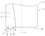
- a rotary cutting tool 1 shown in FIG. 1 is a rotary cutting tool for forming a plurality of spaced dimples (small dents) 22.
- the rotary cutting tool 1 has a rod-like main body 2 and a cutting edge (bottom edge) 3 protruding from the tip 2 a of the main body 2.
- the main body 2 has a round bar shape or a cylindrical shape, and has a diameter of 2 to 10 mm, for example, 4 mm.
- the main body 2 has a tip (bottom surface) 2 a that is substantially orthogonal to the axis 5.
- the shaft center 5 is located at the center of the cross section of the main body 2 and extends in the longitudinal direction.
- the cutting edge 3 is located at a position away from the axis 5 of the main body 2 and protrudes in the axial direction from the tip 2 a of the main body 2.
- the cutting edge 3 is formed continuously with a groove (flute) 7 formed in the main body 2, and protrudes in the axial direction from the tip of the groove 7.
- the cutting edge 3 has a substantially triangular shape, and has a first bottom blade 3a positioned radially outward and a second bottom blade 3b positioned radially inward.
- the first bottom blade 3 a extends obliquely in a straight line from the outer peripheral edge of the tip 2 a of the main body 2 or near the outer peripheral edge toward the axis 5.
- the first bottom blade 3 a has a first angle 3 d in the axial direction with respect to a plane orthogonal to the axis 5.
- the second bottom blade 3b is located between the first bottom blade 3a and the shaft center 5, and extends linearly from the substantially radial center of the main body 2 toward the outer peripheral edge.
- the second bottom blade 3 b has a second angle 3 e in the axial direction with respect to a plane orthogonal to the axis 5.
- the first angle 3d and the second angle 3e are acute angles, for example, 1 to 30 °, specifically 15 °.
- the first bottom blade 3a and the second bottom blade 3b are connected with an angle at the bottom blade tip 3c.
- the cutting edge 3 has a rake face 4 on a face continuous with the bottom of the groove 7.
- the cutting edge 3 has a flank 8 on the opposite side of the rake face 4.
- the flank 8 has a first flank 8a extending from the first bottom blade 3a and a second flank 8b extending from the second bottom blade 3b.
- the first flank 8 a extends obliquely from the first bottom blade 3 a toward the tip 2 a of the main body 2.
- the second flank 8b is substantially triangular and extends obliquely from the second bottom blade 3b toward the tip 2a of the main body 2.
- the first flank 8a has a first angle 3f with respect to the ridgeline of the first flank 8a and the second flank 8b.
- the second flank 8b has a second angle 3g with respect to the ridgeline.
- the first angle 3f and the second angle 3g are such that when the rotary cutting tool 1 is sent to the workpiece 20, the cutting surface of the workpiece 20 does not interfere with the first flank 8a and the second flank 8b.
- the first angle 3 f and the second angle 3 g are set to a size of 20 ⁇ 10 ° when the first flank 8 a and the second flank 8 b are projected onto a plane orthogonal to the axis 5.
- the cutting edge 3 is formed from the same material as the main body 2 of the rotary cutting tool 1 or from a different material.
- the cutting edge 3 and the main body 2 are formed from tool steel, high-speed steel (high-speed tool steel), or cemented carbide.
- the main body 2 is formed from carbon steel, stainless steel, tool steel, high speed steel, cemented carbide, and the cutting edge 3 is formed from polycrystalline diamond (PCD), cubic boron nitride (CBN), ceramics, and cut.
- PCD polycrystalline diamond
- CBN cubic boron nitride
- the blade 3 is joined to the main body 2.
- the cutting edge 3 is formed of the same or different material as that of the main body 2, and a surface treatment such as coating is applied to a region corresponding to the cutting edge 3.
- the surface treatment is performed, for example, by chemical vapor deposition (CVD) or physical vapor deposition (PVD), and the Ti-based TiAlN, TiAlCrN, TiAlCrSiN, or other coating layers such as CVD diamond and diamond-like carbon (DLC) are cut. Used as blade 3.
- CVD chemical vapor deposition
- PVD physical vapor deposition
- Ti-based TiAlN, TiAlCrN, TiAlCrSiN, or other coating layers such as CVD diamond and diamond-like carbon (DLC) are cut. Used as blade 3.
- the rotary cutting tool 1 is set so that the axis 5 has a predetermined angle 10 with respect to the vertical line of the processing surface 21 of the workpiece 20.
- the rotary cutting tool 1 is set so that the tip of the cutting edge 3 has a predetermined depth 11 with respect to the processing surface 21.
- the rotary cutting tool 1 is rotated around an axis 5 and the cutting edge 3 cuts the machining surface 21 in a predetermined rotation angle region.
- the cutting edge 3 moves away from the machining surface 21 in another rotation angle region. Thereby, the cutting edge 3 cuts the processed surface 21 intermittently.
- the rotary cutting tool 1 makes one revolution, one cutting edge 3 creates one dimple.
- the predetermined angle 10 is 60 ° or less, 45 ° or less, 30 ° or less so that the cutting edge 3 cuts the processed surface 21, and preferably the dimple 22 has a predetermined length 22e as shown in FIG. Set to As shown in FIG. 6, the predetermined depth 11 is set such that the maximum depth of the dimple 22 is, for example, 0.1 to 0.001 mm, specifically 0.01 mm.
- the dimple 22 is very small, and the length 22e in the cutting direction is, for example, 0.5 to 1 mm.
- the cutting direction is a direction in which the cutting edge 3 advances with respect to the machining surface 21. For example, a point at which a predetermined portion of the cutting edge 3 reaches the machining surface 21 and a point away from the machining surface 21. It is the direction that tied.
- the dimple 22 has a width orthogonal to the cutting direction.
- the maximum width 22f which is the maximum width, is shorter than the length 22e, and is, for example, half or less of the length 22e.
- the maximum width 22f is, for example, 0.01 to 0.5 mm.
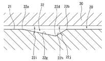
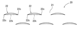
- the dimple 22 has a first side 22a, a second side 22b facing the first side 22a, and both ends 22c connecting the first side 22a and the second side 22b.
- the first side 22a and the second side 22b are curved and are arranged in the width direction.
- the first side 22a and the second side 22b swell in the same direction, in other words, the first side 22a swells in one side in the width direction, and the second side 22b dents in one side in the width direction.
- the dimple 22 has a crescent shape. All or most of the first side 22a and the second side 22b are located in a region on one side of a line 22k connecting both ends 22c.
- the dimple 22 has a first inclined surface 22g extending from the first side 22a and a second inclined surface 22h extending from the second side 22b.
- the first inclined surface 22g has a first depth angle 22i with respect to the processed surface 21, and gradually becomes deeper from the first side 22a toward the second side 22b.
- the second inclined surface 22h has a second depth angle 22j with respect to the processed surface 21, and gradually becomes deeper from the second side 22b toward the first side 22a.
- the second depth angle 22j is larger than the first depth angle 22i.
- the dimple 22 has a groove bottom line 22d connecting the deepest part in the width direction, and the groove bottom line 22d is located closer to the second side 22b than a line connecting the center of the dimple 22 in the width direction.
- friction caused when the workpiece 20 having the dimples 22 and the counterpart material 30 facing the workpiece 20 are relatively moved is reduced by the dimples 22.
- wear powder is generated from one or both of the members, and the wear powder is held in the dimple 22. Most of the wear powder is held near the groove bottom line 22d.
- the workpiece 20 may be moved with respect to the counterpart material 30 in one width direction, specifically, in the direction in which the first side 22 a of the dimple 22 swells.
- the wear powder moves from the first side 22 a toward the second side 22 b with respect to the dimple 22 in the same manner as the counterpart material 30.
- the second inclined surface 22h has a larger inclination angle than the first inclined surface 22g. Therefore, the wear powder is effectively suppressed from being discharged from the dimple 22 by the second inclined surface 22h.
- the workpiece 20 may be moved with respect to the counterpart material 30 in the other side in the width direction, specifically, in the direction opposite to the direction in which the first side 22a of the dimple 22 swells.
- the grease passing through the dimple 22 moves from the second side 22b toward the first side 22a with respect to the dimple 22 in the same manner as the counterpart material 30.
- the inclination angle of the first inclined surface 22g is gentler than that of the second inclined surface 22h. Therefore, the pressure of the grease gradually increases using the first inclined surface 22g. For example, the rate of increase in pressure is smaller than when the pressure increases using the second inclined surface 22h. Therefore, there is little pressure loss and the grease pressure is reliably increased. As a result, the squeeze effect due to the pressure of the grease increases, and the friction between the workpiece 20 and the counterpart material 30 can be efficiently reduced.
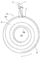
- the workpiece 20 is cylindrical, for example, as shown in FIG. 9, and has an outer peripheral surface 20a and an inner peripheral surface 20b.
- the workpiece 20 has a flat processed surface 21 at one end in the axial direction, and a plurality of dimples 22 are formed on the processed surface 21.
- the plurality of dimples 22 are arranged in the circumferential direction and also in the radial direction of the workpiece 20.
- the plurality of dimples 22 are formed, for example, in a spiral shape on the processing surface 21 and are arranged in parallel in the circumferential direction and the radial direction.
- the processing apparatus 70 includes an X-axis guide 71, an X-direction moving member 72 that can move along the X-axis guide 71, a Y-direction moving member 73 that moves in the Y-axis direction with respect to the X-direction moving member 72, A Z-direction moving member 74 that moves in the Z-axis direction with respect to the direction-moving member 73 is provided.
- the X-axis guide 71 is held by a support base (not shown) and extends in the X-axis direction.
- the X axis direction, the Y axis direction, and the Z axis direction are orthogonal to each other.
- the X direction moving member 72 has, for example, a nut member of a feed screw mechanism.
- the nut member is rotated by a servo motor 96 (see FIG. 11) and moves with respect to a screw shaft provided on the X-axis guide 71.
- the X-direction moving member 72 moves relative to the X-axis guide 71 using a rack and pinion mechanism and a servo motor 96.
- the Y direction moving member 73 and the Z direction moving member 74 are, for example, in the Y direction and the Z direction with respect to the X direction moving member 72 using a feed screw mechanism, a rack and pinion mechanism, and servo motors 97 and 98 (see FIG. 11). Moving.
- the processing apparatus 70 includes a swinging member 75 that is mounted on the Z-direction moving member 74 so as to be capable of adjusting the angle, and a spindle 76 that is provided on the swinging member 75 so as to be rotatable.
- the swing member 75 swings in the X direction or the Y direction with respect to the Z direction moving member 74 using a servo motor 99 (see FIG. 11).
- the rotary cutting tool 1 is mounted on the spindle 76, and the spindle 76 rotates the rotary cutting tool 1 about the axis 5 using the servo motor 100 (see FIG. 11).
- the movement or rotation of each member of the processing apparatus 70 is controlled by a control unit 93 stored in the PC 90 shown in FIG.
- the workpiece 20 is held by the workpiece holding device 80.
- the work holding device 80 includes a base 81 and a table 82 that is rotatably mounted on the upper surface of the base 81.
- the table 82 rotates with respect to the base 81 using a servo motor 101 (see FIG. 11) or the like.
- the workpiece 20 is mounted on the table 82, and the table 82 rotates around the axis 20 c of the workpiece 20 together with the workpiece 20 using the servo motor 101.
- the servo motor 101 is controlled by a control unit 93 stored in the PC 90.
- the movement control and rotation control of each member of the processing device 70 and the work holding device 80 are controlled by the control unit (CPU) 93 in the PC 90 via the I / F circuit 94.
- the ROM 95 stores instructions and data necessary for the execution of the control unit 93.
- Data relating to the machining mode, coordinate data of the workpiece 20, data relating to the rotation speed of the spindle 76, etc. are input via a keyboard or the like and stored in the storage unit (RAM) 92 via the I / F circuit 91.
- the controller 93 transmits a predetermined drive command to each of the motors 96 to 101 based on the stored data, and each of the motors 96 to 101 performs a predetermined drive operation based on the transmission signal.
- the axis 5 of the rotary cutting tool 1 is set at a predetermined angle 10 with respect to the machining surface 21.
- the position in the depth direction (Z direction) is determined in consideration of the cutting depth of the processed surface 21 by the cutting edge 3. While the rotary cutting tool 1 is rotated at a predetermined rotation speed, the workpiece 20 is rotated at a predetermined rotation speed. At the same time, the rotary cutting tool 1 is moved from the outer peripheral surface 20a of the workpiece 20 toward the inner peripheral surface 20b.
- the rotary cutting tool 1 rotates once, the cutting edge 3 cuts the processed surface 21, and one dimple 22 is formed.
- the machining surface 21 rotates with respect to the rotary cutting tool 1, and the machining surface 21 is sent to the rotary cutting tool 1.
- the rotary cutting tool 1 rotates, and the dimple 22 is formed by the cutting edge 3. Thereby, the plurality of dimples 22 are formed in a state of being separated from each other.
- the rotary cutting tool 1 is inclined in the feed direction of the workpiece 20, that is, in the rotation direction of the workpiece 20. Therefore, the dimple 22 is formed so that its longitudinal direction is substantially orthogonal to the feed direction of the workpiece 20.
- the plurality of dimples 22 are juxtaposed in the feed direction and the width direction.
- the rotary cutting tool 1 moves in the radial direction with respect to the processing surface 21, for example, from the outer peripheral surface 20a toward the inner peripheral surface 20b. Therefore, the plurality of dimples 22 are arranged in a spiral shape on the processed surface 21 and arranged in the circumferential direction and the radial direction.
- the rotational speed of the rotary cutting tool 1, the rotational speed of the workpiece 20, and the moving speed of the rotary cutting tool 1 in the radial direction can be adjusted so that the intervals between the plurality of spaced dimples 22 are equal. For example, when the rotary cutting tool 1 is located in the vicinity of the outer peripheral surface 20a of the workpiece 20, the rotary cutting tool 1 is rotated at a high speed. Then, as the rotary cutting tool 1 approaches the inner peripheral surface 20b of the workpiece 20, the rotational speed of the rotary cutting tool 1 is decreased.
- the workpiece 20 is rotated at 17 rpm.
- the rotary cutting tool 1 is moved from the vicinity of the outer peripheral surface 20a of the workpiece 20 toward the inner peripheral surface 20b at a constant speed in the radial direction.
- the rotary cutting tool 1 is moved in the radial direction, and the rotational speed of the rotary cutting tool 1 is gradually reduced from 5100 rpm to 1360 rpm. As a result, the intervals between the plurality of dimples 22 become substantially equal.
- the rotational speed of the rotary cutting tool 1 is made constant, and the rotary cutting tool 1 is moved in the radial direction from the vicinity of the outer peripheral surface 20a toward the inner peripheral surface 20b. Then, the rotational speed of the workpiece 20 can be gradually increased as the rotary cutting tool 1 approaches the inner peripheral surface 20b.
- the intervals between the plurality of dimples 22 can be made substantially equal.
- the small dimples 22 are sequentially formed in the width direction (lateral direction in FIG. 12).
- the plurality of dimples 22 spaced apart from each other are arranged side by side in the width direction on the processing surface 21 of the workpiece 20.
- the dimples 22 are formed so as to be spirally arranged on the processed surface 21, and are arranged in parallel in the radial direction (the vertical direction in FIG. 12) at substantially equal intervals.
- the number and position of the dimples 22 are determined so as to occupy an area of 10-30% of the processed surface 21, for example, about 20%.
- the processed surface 21 on which the dimples 22 are formed faces the counterpart material 30 as shown in FIGS.
- the machining surface 21 is rotated with respect to the counterpart material 30 around the axis 20c (see FIG. 9) of the workpiece 20, for example. Since the dimples 22 are non-circular, the dimples 22 have directivity, and the plurality of dimples 22 face the same direction with respect to the counterpart material 30 that moves relatively.
- the mating member 30 moves from the first side 22 a toward the second side 22 b with respect to the dimple 22.
- the plurality of dimples 22 face the same direction with respect to the counterpart material 30 that rotates relative to the other dimples 22. Therefore, the plurality of dimples 22 have the same effect on the counterpart material 30.
- the mating member 30 may move from the second side 22 b toward the first side 22 a with respect to the dimple 22 as shown in FIG. 8.
- the plurality of dimples 22 are directed in the same direction with respect to the counterpart material 30 that rotates relatively. Therefore, the plurality of dimples 22 have the same effect on the counterpart material 30.
- Dimples 22 are formed on the workpiece 20 as shown in FIG.
- the dimple 22 can reduce the frictional resistance generated between the counterpart material 30 that contacts the workpiece 20 and the workpiece 20.
- wear powder is generated when the workpiece 20 and the mating material 30 come into contact with each other, and the wear powder is sandwiched between the workpiece 20 and the mating material 30 to increase the frictional resistance. There is a case.
- oil is injected between the workpiece 20 and the counterpart material 30, and the dimple 22 is filled with oil. Therefore, oil can be held by the dimples 22 to prevent the workpiece 20 and the counterpart material 30 from contacting each other without oil, or the workpiece 20 and the counterpart material 30 adhere to each other via wear powder. Can be prevented.
- oil is discharged from the dimple 22 between the mating material 30 and the workpiece 20 at a high pressure to form a lubricating film (squeeze effect). This pressure makes it difficult for the mating member 30 to come into contact with the workpiece 20 and reduces the frictional resistance between the mating material 30 and the workpiece 20.
- this embodiment relates to a dimple processing method in which a dimple 22 is formed on a workpiece 20 using a rotary cutting tool 1 as shown in FIG.
- a rotary cutting tool 1 having a cutting edge 3 protruding in the axial direction from a position shifted from the axial center 5 at the tip of a rod-shaped main body 2 is prepared.
- the rotary cutting tool 1 is set so that the axis 5 of the rotary cutting tool 1 is inclined with respect to the vertical line of the processing surface 21 of the workpiece 20.
- the rotary cutting tool 1 and the workpiece 20 are relatively fed so that the rotary cutting tool 1 moves along the machining surface 21 while rotating the rotary cutting tool 1 around the axis 5.
- the machining surface 21 is cut by the cutting edge 3 to form dimples 22 that are spaced apart from each other on the machining surface 21.
- the rotary cutting tool 1 has a cutting edge 3 that is rod-shaped and protrudes in the axial direction at the tip. Therefore, the cutting edge 3 can be rotated with a smaller diameter than the cutting edge protruding in the radial direction. As a result, a small dimple 22 can be formed by the cutting edge 3.
- the cutting edge 3 protrudes from a position shifted from the axis 5 at the tip of the main body 2. Therefore, when the rotary cutting tool 1 is tilted and rotated with respect to the processing surface 21, the cutting edge 3 cuts the processing surface 21 or leaves the processing surface 21. Thus, a plurality of dimples 22 that are separated from each other can be easily formed.
- the cutting edge 3 enters the workpiece 20 obliquely with respect to the processing surface 21 and gradually cuts the processing surface 21 deeply. Then, the cutting edge 3 gradually cuts the machining surface 21 to be shallow, and retreats from the workpiece 20 obliquely. Accordingly, as shown in FIG. 5, the dimple 22 is shallow at both ends 22c and deep at the approximate center in the length direction.
- a dimple formed by irradiating a processed surface with a laser or a dimple formed by shot peening has an abrupt angle that is substantially perpendicular to the processed surface. Compared to such a dimple, the dimple 22 does not have an abrupt angle with respect to the processed surface 21. As a result, the dimple 22 does not have a sudden angle change with respect to the processed surface 21 and easily exhibits a squeeze effect due to grease pressure.
- the cutting edge 3 starts cutting from the cutting start point (for example, one of both ends 22 c of FIG. 5) with respect to the processing surface 21 as the rotary cutting tool 1 rotates, and the cutting end point ( For example, it leaves
- the dimple 22 has a first side 22a and a second side 22b facing each other in a direction orthogonal to a line 22k connecting the cutting start point and the cutting end point.
- the first side 22a is curved so as to swell in one direction with respect to the connected line 22k.
- the second side 22b is curved so as to extend along the connected line 22k or expand in the one direction.
- the dimple 22 is not circular but has a directional shape, for example, a crescent shape. Therefore, as shown in FIG. 6, the moving direction of the counterpart material 30 relative to the dimple 22 can be determined in consideration of the direction of the dimple 22. Thus, the frictional resistance generated between the workpiece 20 and the counterpart material 30 during the relative movement of the workpiece 20 and the counterpart material 30 can be further reduced.
- the dimple 22 having directivity can be formed by projecting the cutting edge 3 from a position shifted from the axis 5 at the tip of the main body 2 and rotating the rotary cutting tool 1 while tilting it with respect to the processing surface 21. Therefore, the directional dimple 22 can be easily and reliably formed.
- the rotary cutting tool 1 is set so that the axis 5 of the rotary cutting tool 1 has an inclination angle of 60 ° or less with respect to the vertical line of the machining surface 21 of the workpiece 20. Therefore, the rotary cutting tool 1 hits the machining surface 21 at an angle close to the vertical, for example, as compared with the case where the axis 5 is parallel to the machining surface 21. Therefore, the bending stress applied to the rotary cutting tool 1 is reduced. As a result, the diameter of the rotary cutting tool 1 can be made relatively small. A smaller dimple 22 can be formed by the small rotary cutting tool 1.
- the axis 5 of the rotary cutting tool 1 is inclined with respect to the vertical line of the processing surface 21 of the workpiece 20. Therefore, the cutting edge 3 can be separated from the processing surface 21, whereby a plurality of dimples 22 that are separated from each other can be formed.
- the dimple 22 has a length 22e which is a cutting direction of the rotary cutting tool 1, a maximum width 22f which is a maximum value of the width orthogonal to the cutting direction and is shorter than the length 22e, and a length 22e. And a maximum depth of 10% or less. Accordingly, the elongated dimple 22 is formed by the rotary cutting tool 1.
- the length 22e of the dimple 22 depends on the cutting direction of the rotary cutting tool 1, that is, the peripheral length of the main body 2 of the rotary cutting tool 1. Therefore, a narrow dimple 22 is formed by the rotary cutting tool 1.
- the dimple 22 has two sides 22 a and 22 b that face in a direction orthogonal to the cutting direction of the rotary cutting tool 1.
- the two sides 22a and 22b are curved in the same direction. Therefore, the dimple 22 has directivity, and good characteristics can be given to the processed surface 21 by using directivity.
- the dimple 22 has a length 22e which is the cutting direction of the rotary cutting tool 1, a width orthogonal to the cutting direction, and a depth groove bottom line 22d connecting the deepest points in each width. .
- the groove bottom line 22d is off the center of the width. Therefore, the groove bottom line 22d can be set at a predetermined position while taking into consideration the effect of collecting the wear powder and the squeeze effect. Thus, the coefficient of friction generated between the workpiece 20 and the counterpart material 30 can be effectively reduced.
- the angles of the inclined surfaces 22g and 22h of the dimple 22 are determined corresponding to the position of the groove bottom line 22d.
- the groove bottom line 22d is brought close to one of the two sides 22a and 22b of the dimple 22, one angle of the inclined surfaces 22g and 22h is increased and the other angle is decreased. Therefore, by removing the position of the groove bottom line 22d from the center of the width, it is possible to obtain the dimple 22 having a large squeeze effect, thereby reducing the frictional resistance between the workpiece 20 and the mating member 30.
- the rotary cutting tool 1 has a first bottom blade 3a positioned radially outward and a second bottom blade 3b positioned radially inward.
- the dimple 22 has a first side 22a (see FIG. 5) formed by the first bottom blade 3a and a second side 22b formed by the second bottom blade 3b.
- the first side 22a and the second side 22b are curved in the same direction. As a result, the dimple 22 has a crescent shape.
- the dimple 22 can reduce the frictional resistance formed between the counterpart material 30 and the workpiece 20.
- the frictional resistance can be affected by the number of dimples 22, the area ratio of the dimples 22 relative to the processed surface 21, the dispersion state of the dimples 22, and the like.
- the dimple 22 is relatively small. Therefore, the area ratio of the dimple 22 to the processed surface 21 can be easily adjusted. Alternatively, the dimples 22 can be easily and evenly distributed with respect to the processed surface 21.
- the dimple 22 has a straight line with the longest diagonal line, for example, a line 22k connecting both ends 22c.
- a line 22k connecting both ends 22c.
- most of the outline of the dimple 22, for example, more than half is located in the region on the same side of the straight line with the longest diagonal line. Therefore, the dimple 22 has directivity and can have a desired effect on the counterpart material 30 shown in FIG.
- the rotary cutting tool 1 is inclined with respect to the machining surface 21, and the inclination direction thereof coincides with the relative feed direction of the rotary cutting tool 1 with respect to the workpiece 20. Therefore, as shown in FIG. 12, the longitudinal direction of the dimple 22 is substantially orthogonal to the relative feed direction. The plurality of dimples 22 are juxtaposed in the relative feed direction.
- a plurality of dimples 22 may be arranged in the pattern shown in FIGS.
- the pattern of FIG. 13 sets the rotary cutting tool 1 diagonally with respect to the relative feed direction with respect to the processing surface 21 of the rotary cutting tool 1.
- a line obtained by projecting the axis 5 of the rotary cutting tool 1 onto the machining surface 21 has an angle with respect to a line parallel to the relative feed direction with respect to the machining surface 21 of the rotary cutting tool 1.
- the rotary cutting tool 1 is inclined with respect to the machining surface 21 in the X direction and the Y direction.
- the longitudinal direction of the dimple 22 extends in the relative feed direction with respect to the machining surface 21 of the rotary cutting tool 1.
- a line obtained by projecting the axis 5 of the rotary cutting tool 1 onto the machining surface 21 is orthogonal to a line parallel to the relative feed direction with respect to the machining surface 21 of the rotary cutting tool 1.
- the rotary cutting tool 1 is installed in the left and right regions of the machining surface 21 and is inclined only in the X direction as shown in FIG.
- the rotary cutting tool 1 is installed in the up-and-down area
- the longitudinal direction of the dimple 22 becomes substantially parallel to the feed direction with respect to the machining surface 21 of the rotary cutting tool 1.
- the plurality of dimples 22 are sequentially formed in the longitudinal direction and are arranged in parallel in the longitudinal direction.
- the rotary cutting tool 1 is also moved in the radial direction with respect to the processing surface 21 as shown in FIG. Therefore, the plurality of dimples 22 are arranged side by side in the radial direction (vertical direction) as shown in FIG.
- a plurality of dimples 22 may be formed on the workpiece 23 shown in FIG. 15 instead of the workpiece 20 shown in FIG.
- the workpiece 23 has an outer peripheral surface that is a processed surface 23a.
- the rotary cutting tool 1 is set so as to have an angle 10 with respect to a line perpendicular to the machining surface 23a. While the rotary cutting tool 1 is rotated about the axis 5, the workpiece 23 is rotated about the axis. The rotary cutting tool 1 is also moved in the axial direction with respect to the workpiece 23.
- a plurality of dimples 22 are juxtaposed in the circumferential direction and arranged in the axial direction on the machining surface 23a of the workpiece 23 shown in FIG. That is, the plurality of dimples 22 are disposed in a spiral shape on the processing surface 23a.
- the first angle 3d and the second angle 3e shown in FIG. 2 can be set to predetermined angles. For example, when the first angle 3d and the second angle 3e are set to 15 °, the dimple 22 shown in FIG. 5 can be formed. When the first angle 3d and the second angle 3e are set to 20 °, the dimple 24 shown in FIG. 16 can be formed.
- the dimple 24 has a first side 24a, a second side 24b, and both ends 24c.
- the first side 24a is a curve and has a larger curvature than the first side 22a indicated by a dotted line.
- the second side 24b is a curved line, has a smaller curvature than the second side 22b indicated by a dotted line, and is close to the line 24k connecting both ends 24c.
- the dimple 24 has a width 24f larger than the width of the dimple 22 indicated by a dotted line.
- the length 24e of the dimple 24 is substantially the same as the length of the dimple 22 indicated by a dotted line.
- the groove bottom line 24d connecting the deepest portions in the width direction is located at a location close to the second side 24b.
- the rotary cutting tool 1 may have a cutting edge 31 shown in FIG. 17 instead of the cutting edge 3 shown in FIG.
- the cutting edge 31 is located at a location deviated from the axis 5 of the main body 2 and protrudes in the axial direction from the tip 2 a of the main body 2.
- the cutting edge 31 protrudes in the axial direction from the tip of the groove 7 formed in the main body 2.
- the cutting edge 31 has a substantially arc-shaped bottom edge 31a.
- the cutting edge 31 has a rake face 4 on a face continuous with the bottom of the groove 7.
- the cutting edge 31 has a flank 31 b on the opposite side of the rake face 4.
- the flank 31 b extends obliquely from the bottom blade 31 a toward the tip 2 a of the main body 2.
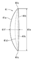
- the dimple 41 has a first side 41a, a second side 41b that faces the first side 41a, and both ends 41c that connect the first side 41a and the second side 41b.
- the first side 41a and the second side 41b are curved and are arranged in the width direction.
- the first side 41a and the second side 41b swell in different directions so as to be separated from each other.
- the dimple 41 has a first side 41a that swells in one side in the width direction and a second side 41b that swells in the other side in the width direction.
- the first side 41a is located in one region with respect to the line 41k connecting both ends 41c, and the whole or most of the second side 41b is located in the other region with respect to the line 41k.
- Both ends 22c of the dimple 22 shown in FIG. 5 connect the first side 22a and the second side 22b at an acute angle.
- both ends 41c of the dimple 41 shown in FIG. 19 connect the first side 41a and the second side 41b in a curved shape corresponding to the shape of the bottom blade 31a.
- the rotary cutting tool 1 may have a cutting edge 32 shown in FIG. 20 instead of the cutting edge 3 shown in FIG.
- the cutting edge 32 is located at a location deviated from the axis 5 of the main body 2 and protrudes in the axial direction from the tip 2 a of the main body 2.
- the cutting edge 32 protrudes in the axial direction from the tip of the groove 7 formed in the main body 2.
- the cutting edge 32 has a substantially triangular shape, and has a first bottom blade 32a positioned radially outward and a second bottom blade 32b positioned radially inward.
- the first bottom blade 32 a extends linearly from the vicinity of the outer peripheral edge of the main body 2 toward the axis 5.
- the first bottom blade 32 a has a first angle 32 d with respect to a plane orthogonal to the axis 5.
- the second bottom blade 32b extends linearly from the substantially radial center of the tip 2a of the main body 2 toward the outer peripheral edge.
- the second bottom blade 32 b has a second angle 32 e with respect to a plane orthogonal to the axis 5.
- the second angle 32e is larger than the first angle 32d and is, for example, 1.5 to 3 times the first angle 32d.
- the cutting edge 32 has a rake face 4 on a face continuous with the bottom of the groove 7.
- the cutting edge 32 has a flank on the opposite side of the rake face 4.
- the flank extends obliquely from the first bottom blade 32a and the second bottom blade 32b toward the tip 2a of the main body 2 in the same manner as the flank 8a, 8b shown in FIG.
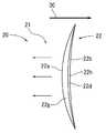
- the cutting edge 32 forms a dimple 42 shown in FIG. 21, for example.
- the dimple 42 has a first side 42a, a second side 42b opposite to the first side 42a, and both ends 42c connecting the first side 42a and the second side 42b.
- the first side 42a and the second side 42b are curved and are arranged in the width direction. Both the first side 42a and the second side 42b swell to one side in the width direction. The whole or most of the first side 42a and the second side 42b are located in one region with respect to the line 42k connecting both ends 42c. Both ends 42c connect the first side 42a and the second side 42b at an acute angle.
- the rotary cutting tool 1 may have a cutting edge 33 shown in FIG. 22 instead of the cutting edge 3 shown in FIG.
- the main body 2 of the rotary cutting tool 1 may have a tip 2b shown in FIG. 22 instead of the tip 2a shown in FIG.
- the tip 2 b of the main body 2 is inclined with respect to a plane orthogonal to the axis 5.
- the cutting edge 33 is located at the tip of the tip 2b in the axial direction.
- the cutting blade 33 has a bottom blade 33a that is located at a position deviated from the axis 5 of the main body 2 and is inclined with respect to a plane orthogonal to the axis 5 at substantially the same angle 33e as the tip 2b of the main body 2.
- the bottom blade 33a extends linearly from the substantially radial center of the tip 2b of the main body 2 toward the outer peripheral edge.
- the radially outer tip of the bottom blade 33a protrudes most in the axial direction.
- the cutting edge 33 has a rake face 4 in a face continuous with the bottom of the groove 7.
- the cutting edge 33 has a flank on the side opposite to the rake face 4.
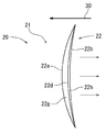
- the cutting edge 33 forms a dimple 43 shown in FIG. 23, for example.
- the dimple 43 has a first side 43a, a second side 43b that faces the first side 43a, and both ends 43c that connect the first side 43a and the second side 43b.
- the first side 43a and the second side 43b are arranged in the width direction.
- the first side 43a is a curve and swells in one side in the width direction.
- the second side 43b is also a curved line, and swells to one side in the width direction with respect to the line 43k connecting both ends 43c.
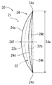
- the rotary cutting tool 1 may have a cutting edge 34 shown in FIG. 24 instead of the cutting edge 3 shown in FIG.
- the cutting edge 34 is located at a location deviated from the axis 5 of the main body 2, and protrudes in the axial direction from the tip 2 a of the main body 2.
- the cutting edge 34 protrudes in the axial direction from the tip of the groove 7 formed in the main body 2.
- the cutting edge 34 is substantially triangular, and includes a first bottom blade 34a positioned radially outward, a second bottom blade 34b positioned radially inward, a first bottom blade 34a, and a second bottom blade 34b. It has the 3rd bottom blade 34c connected in the shape of a curve.
- the first bottom blade 34 a extends linearly from the vicinity of the outer peripheral edge of the main body 2 toward the axis 5.
- the first bottom blade 34 a has a first angle 34 d with respect to a plane orthogonal to the axis 5.
- the second bottom blade 34b extends linearly from the substantially radial center of the tip 2a of the main body 2 toward the outer peripheral edge.
- the second bottom blade 34 b has a second angle 34 e with respect to a plane orthogonal to the axis 5.
- the second angle 34e is larger than the first angle 34d, and is, for example, 1.5 to 3 times the first angle 34d.
- the cutting edge 34 has a rake face 4 on a face continuous with the bottom of the groove 7.
- the cutting edge 34 has a flank on the opposite side of the rake face 4.
- the flank extends obliquely from the first bottom blade 34a, the second bottom blade 34b, and the third bottom blade 34c toward the tip 2a of the main body 2 in the same manner as the flank 8a, 8b shown in FIG.
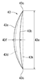
- the cutting edge 34 forms, for example, a dimple 44 shown in FIG.
- the dimple 44 has a first side 44a, a second side 44b facing the first side 44a, and both ends 44c connecting the first side 44a and the second side 44b.
- the first side 44a and the second side 44b are curved and are arranged in the width direction. Both the first side 44a and the second side 44b swell to one side in the width direction. The whole or most of the first side 44a and the second side 44b are located in one region with respect to the line 44k connecting both ends 44c. Both ends 44c are curved and smoothly connect the first side 44a and the second side 44b.
- the rotary cutting tool 1 may have a cutting edge 35 shown in FIG. 26 instead of the cutting edge 3 shown in FIG.
- the cutting edge 35 is located at a location deviated from the axis 5 of the main body 2 and protrudes in the axial direction from the tip 2 a of the main body 2.
- the cutting edge 35 has a substantially triangular shape, and has a first bottom blade 35 a extending from the outer peripheral edge of the main body 2 and a second bottom blade 35 b extending from a substantially central position in the radial direction of the main body 2.
- the first bottom blade 35a extends linearly from the vicinity of the outer peripheral edge of the main body 2 toward the axis 5.
- the first bottom blade 35 a has a first angle 35 d with respect to a plane orthogonal to the axis 5.
- the second bottom blade 35 b extends linearly from the substantially radial center of the main body 2 toward the axis 5.
- the second bottom blade 35 b has a second angle 35 e with respect to a plane orthogonal to the axis 5.
- the 2nd bottom blade 35b is extended toward the axial center 5 similarly to the 1st bottom blade 35a, and is located in a line with the 1st bottom blade 35a in the axial direction.
- the first bottom blade 35a and the second bottom blade 35b are connected at an acute angle by the bottom blade tip 35c.
- the first bottom blade 35a and the second bottom blade 35b are both positioned radially outward from the bottom blade tip 35c.
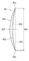
- the cutting edge 35 forms a dimple 45 shown in FIG. 27, for example.
- the dimple 45 has a first side 45a, a second side 45b facing the first side 45a, and both ends 45c connecting the first side 45a and the second side 45b.
- the first side 45a and the second side 45b are curved and are arranged in the width direction. Both the first side 45a and the second side 45b swell to one side in the width direction. The whole or most of the first side 45a and the second side 45b is located in one region with respect to the line 45k connecting both ends 45c.
- the dimple 45 has a groove bottom line 45d connecting the deepest positions in the width direction.
- the groove bottom line 45d is formed by a bottom blade tip 35c shown in FIG.
- the groove bottom line 45d is located at a location beyond the second side 45b rather than the region between the first side 45a and the second side 45b. Therefore, as shown in FIG. 6, the wear powder generated when the workpiece 20 and the counterpart material 30 are slid can be reliably held by the dimple 45.
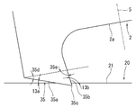
- the rotary cutting tool 1 may have a cutting edge 36 shown in FIG. 28 instead of the cutting edge 3 shown in FIG.
- the cutting edge 36 is located at a location deviated from the axis 5 of the main body 2 and protrudes in the axial direction from the tip 2 a of the main body 2.
- the cutting edge 36 has a substantially triangular shape, and includes a first bottom blade 36 a extending from the outer peripheral edge of the main body 2 and a second bottom blade 36 b extending from a substantially central position in the radial direction of the main body 2.
- the first bottom blade 36a extends linearly from the vicinity of the outer peripheral edge of the main body 2 in a direction away from the axis 5.
- the first bottom blade 36 a has a first angle 36 d with respect to a plane orthogonal to the axis 5.
- the second bottom blade 36b extends linearly in a direction away from the axial center 5 from a substantially radial center of the main body 2.
- the second bottom blade 36 b has a second angle 36 e with respect to a plane orthogonal to the axis 5. Similar to the first bottom blade 36a, the second bottom blade 36b extends radially outward and is aligned with the first bottom blade 36a in the axial direction.
- the first bottom blade 36a and the second bottom blade 36b are connected at an acute-angled bottom blade tip 36c.
- the first bottom blade 36a and the second bottom blade 36b are both located closer to the axis 5 than the bottom blade tip 36c.
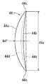
- the cutting edge 36 forms a dimple 46 shown in FIG. 29, for example.
- the dimple 46 has a first side 46a, a second side 46b facing the first side 46a, and both ends 46c connecting the first side 46a and the second side 46b.
- the first side 46a and the second side 46b are curved and are arranged in the width direction. Both the first side 46a and the second side 46b swell to one side in the width direction. The whole or most of the first side 46a and the second side 46b is located in one region with respect to the line 46k connecting both ends 46c.
- the dimple 46 has a groove bottom line 46d connecting the deepest positions in the width direction.
- the groove bottom line 46d is formed by a bottom blade tip 36c shown in FIG.
- the groove bottom line 46d is located at a location beyond the first side 46a rather than the region between the first side 46a and the second side 46b. Therefore, as shown in FIG. 6, the wear powder generated when the workpiece 20 and the counterpart material 30 are slid can be reliably held by the dimples 46.
- the rotary cutting tool 1 may have a cutting edge 37 shown in FIG. 30 instead of the cutting edge 3 shown in FIG.
- the cutting edge 37 is located at a location deviated from the axis 5 of the main body 2, and protrudes in the axial direction from the tip 2 a of the main body 2.
- the cutting edge 37 is substantially rectangular, and includes a first bottom blade 37a extending in the axial direction from the outer peripheral edge of the main body 2, and a second bottom blade 37b extending in the radial direction from the tip of the first bottom blade 37a.
- the third bottom blade 37c extends in the axial direction from the inner peripheral tip of the second bottom blade 37b.
- the first bottom blade 37a extends linearly from the vicinity of the outer peripheral edge of the main body 2 substantially in parallel with the axis 5.
- the second bottom blade 37b extends at an angle larger than 90 ° with respect to the first bottom blade 37a.
- the second bottom blade 37b is substantially parallel to the machining surface 21 when the axis 5 of the rotary cutting tool 1 is inclined at a predetermined angle 10 (see FIG. 1) with respect to the vertical line of the machining surface 21. To position. That is, the second bottom blade 37 b is inclined at an angle 10 with respect to a plane orthogonal to the axis 5.
- the third bottom blade 37c is substantially orthogonal to the inner peripheral tip of the second bottom blade 37b and extends linearly.
- the third bottom blade 37 c has an angle 37 e with respect to a line parallel to the axis 5.
- the distance between the first bottom blade 37a and the third bottom blade 37c decreases as the distance from the second bottom blade 37b increases.
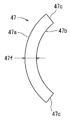
- the cutting edge 37 forms, for example, a dimple 47 shown in FIG.
- the dimple 47 has a first side 47a, a second side 47b facing the first side 47a, and both ends 47c connecting the first side 47a and the second side 47b.
- the first side 47a and the second side 47b are curved and are arranged in the width direction. Both the first side 47a and the second side 47b swell in one side in the width direction and are substantially parallel. Therefore, the dimple 47 has a substantially constant width and extends in a C shape. Both ends 47c of the dimple 47 are substantially linear.
- the rotary cutting tool 1 may have a cutting edge 38 shown in FIG. 32 instead of the cutting edge 3 shown in FIG.
- the cutting edge 38 is located at a location deviated from the axis 5 of the main body 2 and protrudes in the axial direction from the tip 2 a of the main body 2.
- the cutting edge 38 is polygonal and has a first bottom edge 38a, a second bottom edge 38b, and a third bottom edge 38c in succession.
- the first bottom blade 38 a extends linearly from the vicinity of the outer peripheral edge of the main body 2 toward the axis 5.
- the first bottom blade 38 a has a first angle 38 d with respect to a surface perpendicular to the axis 5 from the vicinity of the outer peripheral edge of the main body 2.
- the second bottom blade 38b extends linearly from the tip of the first bottom blade 38a and further away from the main body 2 and toward the axis 5.
- the second bottom blade 38 b has a second angle 38 e that is smaller than the first angle 38 d with respect to a plane perpendicular to the axis 5.
- the third bottom blade 38c linearly connects the tip of the second bottom blade 38b and the substantially center of the main body 2 in the radial direction.
- the third bottom blade 38 c has a third angle 38 f with respect to a plane perpendicular to the axis 5.
- the rotary cutting tool 1 may have one cutting edge 3 as shown in FIG. 2 or the like, or may have a plurality of cutting edges 39a and 39b as shown in FIG.
- the cutting edge 39a and the cutting edge 39b are located, for example, at locations facing each other with the axis 5 interposed therebetween.
- the cutting edge 39a and the cutting edge 39b are positioned at a predetermined distance in the circumferential direction, for example.
- the cutting edge 39a is formed, for example, in the same manner as the cutting edge 31 shown in FIG.
- the cutting edge 39b is formed similarly to the cutting edge 32 shown in FIG. 20, for example.
- dimples 48 and 49 shown in FIG. 34 can be formed by using the rotary cutting tool 1 shown in FIG.
- the rotary cutting tool 1 is set so that the rotary cutting tool 1 is at a predetermined angle 10 with respect to the vertical line of the machining surface 21.
- the workpiece 20 and the rotary cutting tool 1 are relatively moved while rotating the rotary cutting tool 1 about the axis 5.
- the cutting edge 39 a forms the dimple 48
- the cutting edge 39 b forms the dimple 49.
- the dimples 48 and the dimples 49 are alternately arranged in the relative movement direction of the rotary cutting tool 1 with respect to the workpiece 20.
- the dimple 48 has two opposite sides, and the two opposite sides swell in a direction away from each other.
- the dimple 49 has two opposite sides and extends so that the two opposite sides swell in the same direction.
- the dimples 48 and 49 are arranged side by side in a direction orthogonal to the respective longitudinal directions.
- the dimple 34 may be configured to form the dimples 50 and 51 shown in FIG. 35 instead of the dimples 48 and 49 shown in FIG. 34, and the workpiece 20 may be processed by the rotary cutting tool 1.
- the dimple 50 has two opposite sides and extends so that the two opposite sides swell in the same direction.
- the dimple 50 has a length L1 in the cutting direction (longitudinal direction).
- the dimple 51 has a crescent shape similar to that of the dimple 50, and has a length L2 in the cutting direction (longitudinal direction) shorter than that of the dimple 50.
- the dimples 50 and 51 are alternately arranged in a direction orthogonal to the longitudinal direction of the dimple 50.
- the rotary cutting tool 1 can be provided with a plurality of types of cutting edges so as to form a plurality of types of dimples.
- a plurality of rotary cutting tools are prepared, and cutting blades having different shapes are provided on each rotary cutting tool.
- the workpiece 20 may be processed using a plurality of rotary cutting tools, and each shape of dimple may be formed by each rotary cutting tool.
- the dimples are formed by a plurality of first dimples 48, 50 formed by cutting edges and other cutting edges different from the cutting edges, and are located between the first dimples 48, 50.
- Second dimples 49 and 51 are included. Accordingly, dimples having different shapes are alternately arranged. Thereby, as shown in FIG. 6, the frictional resistance caused by the relative movement of the workpiece 20 and the counterpart material 30 can be more effectively reduced.
- the first dimples 48 and 50 may be formed using a first rotary cutting tool
- the second dimples 49 and 51 may be formed using a second rotary cutting tool.
- the position and rotation angle of the second rotary cutting tool are set to the position and rotation angle of the first rotary cutting tool so that the positions of the first dimples 48 and 50 and the second dimples 49 and 51 have a predetermined relationship. It is necessary to make adjustments while taking this into consideration.
- the first rotary cutting tool and the second rotary cutting tool may have different shapes of cutting edges.
- the first dimples 48 and 50 and the second dimples 49 and 51 are formed by cutting blades 39a and 39b having different shapes. Then, as shown in FIG. 33, these cutting edges 39a and 39b may be provided in the same rotary cutting tool 1. In this case, the positional relationship between the plurality of cutting edges 39 a and 39 b is determined in advance in the rotary cutting tool 1. Therefore, dimples having different shapes can be easily formed at predetermined positions as compared with the case where a plurality of rotary cutting tools are controlled in consideration of the mutual positional relationship.
- the plurality of dimples 22 shown in FIG. 12 are arranged side by side in a direction substantially orthogonal to the longitudinal direction of the dimples 22.
- the plurality of dimples may be arranged in the pattern shown in FIGS.
- the plurality of dimples 60 shown in FIG. 36 have first dimples 60a arranged in one row and second dimples 60b arranged in one row.
- the first dimples 60a are arranged so that the longitudinal direction is inclined with respect to the feed direction indicated by the arrow.
- the plurality of first dimples 60a are arranged in parallel in the feeding direction at predetermined intervals, and the respective longitudinal directions are arranged in parallel.
- the second dimple 60b is inclined at a different angle from the first dimple 60a with respect to the feed direction.
- the plurality of second dimples 60b are arranged in parallel in the feed direction at a predetermined interval, and the respective longitudinal directions are arranged in parallel.
- the second dimple 60b is located in a shape and location that is symmetrical to the first dimple 60a with respect to a line 60c extending between the first dimple 60a arranged in a row and the second dimple 60b arranged in a row.
- the 37 has a first dimple 61a arranged in one row and a second dimple 61b arranged in one row.
- the first dimples 61a are arranged so that the longitudinal direction is inclined with respect to the feed direction indicated by the arrow.
- the plurality of first dimples 61a are arranged in parallel in the feeding direction at a predetermined interval, and the respective longitudinal directions are arranged in parallel.
- the second dimple 61b is inclined at a different angle from the first dimple 61a with respect to the feed direction.
- the second dimple 61b is inclined at an angle symmetrical to the first dimple 61a with respect to a line 61c extending between the first dimple 61a arranged in a row and the second dimple 61b arranged in a row.
- the plurality of second dimples 61b are arranged in parallel in the feeding direction at a predetermined interval, and the respective longitudinal directions are arranged in parallel.
- the plurality of first dimples 61a and the plurality of second dimples 61b are alternately arranged in the feed direction indicated by the arrows.
- the positions of the first dimple 61a and the second dimple 61b in the direction orthogonal to the feeding direction are determined so as to partially overlap when viewed in the feeding direction.
- the plurality of dimples 62 shown in FIG. 38 have first dimples 62a arranged in one row and second dimples 62b arranged in one row.
- the first dimples 62a are arranged so that the longitudinal direction is inclined with respect to the feed direction indicated by the arrow.
- the plurality of first dimples 62a are arranged in parallel in the feeding direction at a predetermined interval, and the respective longitudinal directions are arranged in parallel.
- the second dimple 62b is inclined at an angle different from that of the first dimple 62a with respect to the feed direction.
- the longitudinal end of the first dimple 62a and the longitudinal end of the second dimple 62b are in contact with each other.
- the first dimple 62a and the second dimple 62b are located at symmetrical positions with respect to a line 62c extending between the first dimple 62a arranged in a row and the second dimple 62b arranged in a row, and have a symmetrical angle. Having a symmetrical shape.
- the plurality of dimples 63 shown in FIG. 39 have first dimples 63a arranged in one row and second dimples 63b arranged in one row.
- the first dimples 63a are arranged so that the longitudinal direction is inclined with respect to the feed direction indicated by the arrow.
- the plurality of first dimples 63a are arranged in parallel in the feeding direction at a predetermined interval, and the respective longitudinal directions are arranged in parallel.
- the second dimple 63b is inclined at an angle different from that of the first dimple 63a with respect to the feed direction. A portion of the end portion in the longitudinal direction of the first dimple 63a and the end portion in the longitudinal direction of the second dimple 63b overlap each other. Thereby, the first dimple 63a and the second dimple 63b are continuous.
- the first dimple 63a and the second dimple 63b are located at symmetrical positions with respect to a line 63c extending between the first dimple 63a arranged in a row and the second dimple 63b arranged in a row, and have a symmetrical angle. Having a symmetrical shape.
- first dimple 64a arranged in a row and a second dimple 64b arranged in a row.
- the first dimples 64a are arranged so that the longitudinal direction is inclined with respect to the feed direction indicated by the arrow.
- the plurality of first dimples 64a are arranged in parallel in the feeding direction at a predetermined interval, and the respective longitudinal directions are arranged in parallel.
- the second dimple 64b is inclined at an angle different from that of the first dimple 64a with respect to the feed direction, and intersects the first dimple 64a.
- the first dimple 64a and the second dimple 64b are located at symmetrical positions with respect to the line 64c connecting the intersecting points, have a symmetrical angle, and have a symmetrical shape.
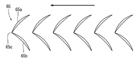
- first dimple 65a arranged in a row and a second dimple 65b arranged in a row.
- the first dimples 65a are arranged so that the longitudinal direction is inclined with respect to the feed direction indicated by the arrow.
- the plurality of first dimples 65a are arranged in parallel in the feed direction at a predetermined interval, and the respective longitudinal directions are arranged in parallel.
- the second dimple 65b is inclined at a different angle from the first dimple 65a with respect to the feed direction.
- the end portion in the longitudinal direction of the first dimple 65a and the end portion in the longitudinal direction of the second dimple 65b are in contact at a common point 65c.
- the second dimple 65b has a positional relationship and shape obtained by rotating the first dimple 65a around the common point 65c.
- the cutting edge 3 shown in FIG. 2 etc. is provided in the vicinity of the outer periphery of the main body 2. Instead of this, the cutting edge may be provided in the vicinity of the center of the main body 2 in the radial direction. As shown in FIG. 1, the cutting edge 3 is located at a location where the entire cutting edge 3 is off the axis 5. Instead of this, the cutting edge 3 may be located at a position where the bottom edge is detached from the axis 5 while at least a part thereof is located at the axis 5.
- the cutting blade may have a triangular bottom blade shown in FIG. 2 or the like, or an arc-shaped bottom blade shown in FIG. Instead of this, the cutting edge may have a bottom edge having a free curved shape or a combination of a plurality of shapes.
- the rake face of the cutting edge may be parallel to the axis or may be inclined with respect to a plane parallel to the axis.
- the plurality of dimples may be completely separated as shown in FIG. 12, or may be separated from the second dimple while partially overlapping with the first dimple as shown in FIG.
- the dimples may be arranged at regular intervals as shown in FIG. 12, or may be arranged at irregular intervals.
- the rotary cutting tool 1 may have one cutting edge 3 as shown in FIG. 2, or may have two cutting edges 39a and 39b as shown in FIG. It may replace with this and the rotary cutting tool 1 may have three or more cutting blades spaced apart in the circumferential direction.
- the main body 2 of the rotary cutting tool 1 may have a round bar shape as shown in FIG. 1 or may have a bar shape with a polygonal cross section.
- the processed surface 21 may be a flat surface as shown in FIG. 1, or may be a cylindrical or cylindrical outer peripheral surface or inner peripheral surface as shown in FIG.
- dimples may be formed on the outer peripheral surface of the journal bearing shaft.
- Dimples may be formed on the inner peripheral surface of the bearing.
- Dimples may be formed on the pump parts that rotate.
- Dimples may be formed on the outer peripheral surface of the piston skirt.
- the rotary cutting tool 1 and the workpiece 20 can be relatively sent.
- the rotary cutting tool 1 and the workpiece 20 may be relatively sent by moving the rotary cutting tool 1 relative to the workpiece 20, for example, by moving it in the circumferential direction.
- the feed speed is slower than the cutting speed of the cutting edge determined by the rotational speed of the rotary cutting tool 1, and is, for example, 1 to 20 m / min.
Landscapes
- Engineering & Computer Science (AREA)
- Mechanical Engineering (AREA)
- Turning (AREA)
- Milling Processes (AREA)
Abstract
L'invention concerne un procédé de formation de dépressions qui utilise un outil de coupe rotatif (1) pour former des dépressions (22) dans un matériau (20) à usiner. L'outil de coupe rotatif (1) est préparé, l'outil de coupe rotatif (1) étant pourvu d'une lame de coupe (3) qui est disposée à l'extrémité avant d'un corps en forme de tige (2) et qui dépasse axialement à partir d'une position décalée par rapport à un axe (5). L'outil de coupe rotatif (1) est fixé de sorte que l'axe (5) de l'outil de coupe rotatif (1) soit incliné par rapport à une ligne perpendiculaire à une surface (21) à usiner du matériau (20) à usiner. Pendant que l'outil de coupe rotatif (1) tourne par rapport à l'axe (5), l'outil de coupe rotatif (1) et le matériau (20) à usiner sont avancés l'un par rapport à l'autre de sorte que l'outil de coupe rotatif (1) se déplace le long de la surface (21) à usiner. La surface (21) à usiner est découpée par la lame de coupe (3) pour former les dépressions (22) dans la surface (21) à usiner, les dépressions (22) étant situées à une certaine distance l'une de l'autre.
Priority Applications (4)
| Application Number | Priority Date | Filing Date | Title |
|---|---|---|---|
| CN201780031002.9A CN109153086B (zh) | 2016-05-19 | 2017-05-15 | 使用了旋转切削工具的凹坑加工方法 |
| EP17799335.9A EP3459664A4 (fr) | 2016-05-19 | 2017-05-15 | Procédé de formation de dépressions grâce à un outil de coupe rotatif |
| JP2018518285A JP6651616B2 (ja) | 2016-05-19 | 2017-05-15 | 回転切削工具を用いたディンプル加工方法 |
| US16/301,785 US10702931B2 (en) | 2016-05-19 | 2017-05-15 | Dimple processing method using rotary cutting tool |
Applications Claiming Priority (2)
| Application Number | Priority Date | Filing Date | Title |
|---|---|---|---|
| JP2016100404 | 2016-05-19 | ||
| JP2016-100404 | 2016-05-19 |
Publications (1)
| Publication Number | Publication Date |
|---|---|
| WO2017199911A1 true WO2017199911A1 (fr) | 2017-11-23 |
Family
ID=60325152
Family Applications (1)
| Application Number | Title | Priority Date | Filing Date |
|---|---|---|---|
| PCT/JP2017/018204 WO2017199911A1 (fr) | 2016-05-19 | 2017-05-15 | Procédé de formation de dépressions grâce à un outil de coupe rotatif |
Country Status (5)
| Country | Link |
|---|---|
| US (1) | US10702931B2 (fr) |
| EP (1) | EP3459664A4 (fr) |
| JP (1) | JP6651616B2 (fr) |
| CN (1) | CN109153086B (fr) |
| WO (1) | WO2017199911A1 (fr) |
Cited By (2)
| Publication number | Priority date | Publication date | Assignee | Title |
|---|---|---|---|---|
| US20180154461A1 (en) * | 2015-06-29 | 2018-06-07 | Kanefusa Kabushiki Kaisha | Dimples processing method by means of end milling and end mill |
| WO2019202911A1 (fr) * | 2018-04-18 | 2019-10-24 | 兼房株式会社 | Pièce alvéolée et procédé d'alvéolage |
Families Citing this family (2)
| Publication number | Priority date | Publication date | Assignee | Title |
|---|---|---|---|---|
| DE102017124187A1 (de) * | 2017-10-17 | 2019-04-18 | Kendrion (Villingen) Gmbh | Verfahren zum Herstellen von einer oder mehreren konkaven Ausnehmungen auf einem insbesondere im Wesentlichen zylindrischen Grundkörper insbesondere auf einem Magnetanker, Stößel oder einer Rückschlussplatte, Magnetanker, Stößel oder Rückschlussplatten, welcher eine oder mehrere nach diesem Verfahren hergestellte Ausnehmungen aufweist, sowie elektro-magnetischer Aktuator mit einem derartigen Magnetanker und/ oder einer derartigen Rückschlussplatte |
| CN114096378A (zh) * | 2019-09-13 | 2022-02-25 | 兼房株式会社 | 凹痕加工方法 |
Citations (3)
| Publication number | Priority date | Publication date | Assignee | Title |
|---|---|---|---|---|
| JPH1052998A (ja) * | 1996-08-08 | 1998-02-24 | Kanefusa Kk | 回転切削工具による被加工材表面の加飾方法 |
| JP2003084370A (ja) * | 2001-09-12 | 2003-03-19 | Masami Masuda | 異方性ディンプル面 |
| JP2008246587A (ja) * | 2007-03-29 | 2008-10-16 | Nagasaki Prefecture | フライス加工の加工制御方法 |
Family Cites Families (18)
| Publication number | Priority date | Publication date | Assignee | Title |
|---|---|---|---|---|
| US2890627A (en) * | 1950-03-04 | 1959-06-16 | Gen Motors Corp | Method for making lens mold |
| FR1405807A (fr) * | 1963-03-21 | 1965-07-16 | Commissariat Energie Atomique | Procédé d'usinage d'éléments tubulaires à ailettes pour échangeurs de chaleur |
| JP3305120B2 (ja) * | 1994-06-30 | 2002-07-22 | キヤノン株式会社 | 光学素子の成形用型部材の加工方法 |
| JP2001198718A (ja) * | 2000-01-19 | 2001-07-24 | Kawatetsu Machinery Co Ltd | 曲面切削法 |
| JP2002361510A (ja) | 2001-06-07 | 2002-12-18 | Masami Masuda | 微細凹面のミーリング加工法とその装置 |
| JP2003236809A (ja) * | 2002-02-13 | 2003-08-26 | Nisshin Mokuzai Kogyo Kk | 木質材等の表面加工法及び表面加工された木質材 |
| JP2007021692A (ja) * | 2005-07-20 | 2007-02-01 | Makino Milling Mach Co Ltd | 切削加工方法及び装置 |
| US9575485B2 (en) * | 2006-07-25 | 2017-02-21 | Mori Seiki Co., Ltd. | Compound machining method and apparatus |
| EP1927444B1 (fr) * | 2006-12-01 | 2012-08-15 | Kälin & Co. AG | Lame de rabot |
| US20090041553A1 (en) * | 2007-08-06 | 2009-02-12 | 3M Innovative Properties Company | Fly-cutting system and method, and related tooling and articles |
| CN101398494A (zh) * | 2007-09-28 | 2009-04-01 | 群康科技(深圳)有限公司 | 棱镜片、棱镜片制造方法、背光模组及液晶显示装置 |
| DK2497592T3 (da) * | 2009-11-05 | 2014-02-03 | Konica Minolta Advanced Layers | Skærende værktøj, fremgangsmåde til fremstilling af et formværktøj |
| DE102009052642A1 (de) * | 2009-11-10 | 2011-05-12 | Timura Holzmanufaktur Gmbh | Verfahren zum Herstellen einer strukturierten, Erhöhungen und Vertiefungen aufweisenden Oberfläche an einem Werkstück aus Holz |
| CN102574221B (zh) * | 2010-04-19 | 2013-12-11 | 山崎马扎克公司 | 切削加工方法及切削加工装置 |
| EP2832494B1 (fr) | 2012-03-30 | 2021-09-15 | Makino Milling Machine Co., Ltd. | Procédé d'usinage de pièces, machine-outil, dispositif générateur de trajet d'outil et programme générateur de trajet d'outil |
| US8991287B2 (en) * | 2012-07-06 | 2015-03-31 | Caterpillar Inc. | Surface dimpling on rotating work piece using rotation cutting tool |
| CN104339007A (zh) * | 2013-07-30 | 2015-02-11 | 常州耐之力刀具制造有限公司 | 单刃铝用铣刀 |
| BR112016008261B1 (pt) * | 2013-11-01 | 2022-01-04 | Kanefusa Kabushiki Kaisha | Método de processamento para superfície de uma peça de trabalho que usa ferramenta de corte giratória |
-
2017
- 2017-05-15 WO PCT/JP2017/018204 patent/WO2017199911A1/fr active Application Filing
- 2017-05-15 EP EP17799335.9A patent/EP3459664A4/fr active Pending
- 2017-05-15 JP JP2018518285A patent/JP6651616B2/ja active Active
- 2017-05-15 US US16/301,785 patent/US10702931B2/en active Active
- 2017-05-15 CN CN201780031002.9A patent/CN109153086B/zh active Active
Patent Citations (3)
| Publication number | Priority date | Publication date | Assignee | Title |
|---|---|---|---|---|
| JPH1052998A (ja) * | 1996-08-08 | 1998-02-24 | Kanefusa Kk | 回転切削工具による被加工材表面の加飾方法 |
| JP2003084370A (ja) * | 2001-09-12 | 2003-03-19 | Masami Masuda | 異方性ディンプル面 |
| JP2008246587A (ja) * | 2007-03-29 | 2008-10-16 | Nagasaki Prefecture | フライス加工の加工制御方法 |
Non-Patent Citations (1)
| Title |
|---|
| See also references of EP3459664A4 * |
Cited By (7)
| Publication number | Priority date | Publication date | Assignee | Title |
|---|---|---|---|---|
| US20180154461A1 (en) * | 2015-06-29 | 2018-06-07 | Kanefusa Kabushiki Kaisha | Dimples processing method by means of end milling and end mill |
| US10857602B2 (en) * | 2015-06-29 | 2020-12-08 | Kanefusa Kabushiki Kaisha | Dimples processing method by means of end milling and end mill |
| WO2019202911A1 (fr) * | 2018-04-18 | 2019-10-24 | 兼房株式会社 | Pièce alvéolée et procédé d'alvéolage |
| CN111989501A (zh) * | 2018-04-18 | 2020-11-24 | 兼房株式会社 | 带凹部的工件及凹部的加工方法 |
| KR20200140837A (ko) * | 2018-04-18 | 2020-12-16 | 가네후사 가부시키가이샤 | 딤플이 형성된 피가공물 및 딤플 가공 방법 |
| EP3783239A4 (fr) * | 2018-04-18 | 2021-12-22 | Kanefusa Kabushiki Kaisha | Pièce alvéolée et procédé d'alvéolage |
| KR102601952B1 (ko) * | 2018-04-18 | 2023-11-14 | 가네후사 가부시키가이샤 | 딤플이 형성된 피가공물 및 딤플 가공 방법 |
Also Published As
| Publication number | Publication date |
|---|---|
| EP3459664A1 (fr) | 2019-03-27 |
| US10702931B2 (en) | 2020-07-07 |
| CN109153086B (zh) | 2020-12-22 |
| US20190151961A1 (en) | 2019-05-23 |
| JPWO2017199911A1 (ja) | 2018-12-06 |
| EP3459664A4 (fr) | 2020-01-15 |
| JP6651616B2 (ja) | 2020-02-19 |
| CN109153086A (zh) | 2019-01-04 |
Similar Documents
| Publication | Publication Date | Title |
|---|---|---|
| WO2017199911A1 (fr) | Procédé de formation de dépressions grâce à un outil de coupe rotatif | |
| JP5745769B2 (ja) | フライスカッター製造方法 | |
| JP5204537B2 (ja) | 歯車を研削するための研削機械 | |
| JP5864035B1 (ja) | スカイビング加工用カッタ | |
| JP6730266B2 (ja) | 多回転刃部を持ったアキシャルホブ | |
| US7237989B2 (en) | Milling method used for producing structural components | |
| JP6679620B2 (ja) | 回転切削工具を用いたディンプル加工方法及びディンプル加工用回転切削工具 | |
| JP2010162677A (ja) | 小径cbnボールエンドミル | |
| CA2810179A1 (fr) | Procede et appareil destines a l'usinage non rotatif | |
| JP2006231504A (ja) | エンドミル、加工装置、切削方法及び、加工物 | |
| JP6819099B2 (ja) | 歯車加工方法 | |
| WO2020195511A1 (fr) | Procédé de fabrication de foret | |
| WO2021049260A1 (fr) | Procédé d'usinage de fossette | |
| WO2022145013A1 (fr) | Procédé de traitement de taillage d'engrenages | |
| JP6565380B2 (ja) | 切削装置、切削方法及び環状工具 | |
| JP7365524B1 (ja) | ウエーブエンボス成形金型の加工方法 | |
| JP2004130434A (ja) | 曲り歯かさ歯車の加工方法 | |
| JP7364921B2 (ja) | エンドミル | |
| JP2020142349A (ja) | 製造装置および製造方法 | |
| KR20240011689A (ko) | 피가공물 치형 배열체의 치형 플랭크 영역을 기계가공하기 위한 방법, 챔퍼링 공구, 이 방법을 수행하기 위한 제어 명령어를 갖는 제어 프로그램, 및 기어 절삭기 | |
| JP2022188412A (ja) | ディンプル加工方法 | |
| JP2023101845A (ja) | 歯車加工用転造工具 | |
| JP2018149630A (ja) | 転削工具を用いた転削加工方法 | |
| JP2004181606A (ja) | 切削加工方法 |
Legal Events
| Date | Code | Title | Description |
|---|---|---|---|
| WWE | Wipo information: entry into national phase |
Ref document number: 2018518285 Country of ref document: JP |
|
| NENP | Non-entry into the national phase |
Ref country code: DE |
|
| 121 | Ep: the epo has been informed by wipo that ep was designated in this application |
Ref document number: 17799335 Country of ref document: EP Kind code of ref document: A1 |
|
| ENP | Entry into the national phase |
Ref document number: 2017799335 Country of ref document: EP Effective date: 20181219 |