WO2017199681A1 - ガラス板の製造方法及びその製造装置、並びにガラス板の搬送装置 - Google Patents
ガラス板の製造方法及びその製造装置、並びにガラス板の搬送装置 Download PDFInfo
- Publication number
- WO2017199681A1 WO2017199681A1 PCT/JP2017/015877 JP2017015877W WO2017199681A1 WO 2017199681 A1 WO2017199681 A1 WO 2017199681A1 JP 2017015877 W JP2017015877 W JP 2017015877W WO 2017199681 A1 WO2017199681 A1 WO 2017199681A1
- Authority
- WO
- WIPO (PCT)
- Prior art keywords
- glass
- original plate
- glass original
- plate
- side end
- Prior art date
- Legal status (The legal status is an assumption and is not a legal conclusion. Google has not performed a legal analysis and makes no representation as to the accuracy of the status listed.)
- Ceased
Links
Images



Classifications
-
- C—CHEMISTRY; METALLURGY
- C03—GLASS; MINERAL OR SLAG WOOL
- C03B—MANUFACTURE, SHAPING, OR SUPPLEMENTARY PROCESSES
- C03B35/00—Transporting of glass products during their manufacture, e.g. hot glass lenses, prisms
- C03B35/14—Transporting hot glass sheets or ribbons, e.g. by heat-resistant conveyor belts or bands
- C03B35/20—Transporting hot glass sheets or ribbons, e.g. by heat-resistant conveyor belts or bands by gripping tongs or supporting frames
-
- B—PERFORMING OPERATIONS; TRANSPORTING
- B28—WORKING CEMENT, CLAY, OR STONE
- B28D—WORKING STONE OR STONE-LIKE MATERIALS
- B28D5/00—Fine working of gems, jewels, crystals, e.g. of semiconductor material; apparatus or devices therefor
-
- B—PERFORMING OPERATIONS; TRANSPORTING
- B65—CONVEYING; PACKING; STORING; HANDLING THIN OR FILAMENTARY MATERIAL
- B65G—TRANSPORT OR STORAGE DEVICES, e.g. CONVEYORS FOR LOADING OR TIPPING, SHOP CONVEYOR SYSTEMS OR PNEUMATIC TUBE CONVEYORS
- B65G49/00—Conveying systems characterised by their application for specified purposes not otherwise provided for
- B65G49/05—Conveying systems characterised by their application for specified purposes not otherwise provided for for fragile or damageable materials or articles
- B65G49/06—Conveying systems characterised by their application for specified purposes not otherwise provided for for fragile or damageable materials or articles for fragile sheets, e.g. glass
-
- B—PERFORMING OPERATIONS; TRANSPORTING
- B65—CONVEYING; PACKING; STORING; HANDLING THIN OR FILAMENTARY MATERIAL
- B65G—TRANSPORT OR STORAGE DEVICES, e.g. CONVEYORS FOR LOADING OR TIPPING, SHOP CONVEYOR SYSTEMS OR PNEUMATIC TUBE CONVEYORS
- B65G49/00—Conveying systems characterised by their application for specified purposes not otherwise provided for
- B65G49/05—Conveying systems characterised by their application for specified purposes not otherwise provided for for fragile or damageable materials or articles
- B65G49/06—Conveying systems characterised by their application for specified purposes not otherwise provided for for fragile or damageable materials or articles for fragile sheets, e.g. glass
- B65G49/063—Transporting devices for sheet glass
- B65G49/066—Transporting devices for sheet glass being suspended; Suspending devices, e.g. clamps, supporting tongs
-
- C—CHEMISTRY; METALLURGY
- C03—GLASS; MINERAL OR SLAG WOOL
- C03B—MANUFACTURE, SHAPING, OR SUPPLEMENTARY PROCESSES
- C03B17/00—Forming molten glass by flowing-out, pushing-out, extruding or drawing downwardly or laterally from forming slits or by overflowing over lips
- C03B17/06—Forming glass sheets
-
- C—CHEMISTRY; METALLURGY
- C03—GLASS; MINERAL OR SLAG WOOL
- C03B—MANUFACTURE, SHAPING, OR SUPPLEMENTARY PROCESSES
- C03B33/00—Severing cooled glass
- C03B33/02—Cutting or splitting sheet glass or ribbons; Apparatus or machines therefor
-
- C—CHEMISTRY; METALLURGY
- C03—GLASS; MINERAL OR SLAG WOOL
- C03B—MANUFACTURE, SHAPING, OR SUPPLEMENTARY PROCESSES
- C03B33/00—Severing cooled glass
- C03B33/02—Cutting or splitting sheet glass or ribbons; Apparatus or machines therefor
- C03B33/023—Cutting or splitting sheet glass or ribbons; Apparatus or machines therefor the sheet or ribbon being in a horizontal position
- C03B33/03—Glass cutting tables; Apparatus for transporting or handling sheet glass during the cutting or breaking operations
-
- C—CHEMISTRY; METALLURGY
- C03—GLASS; MINERAL OR SLAG WOOL
- C03B—MANUFACTURE, SHAPING, OR SUPPLEMENTARY PROCESSES
- C03B33/00—Severing cooled glass
- C03B33/02—Cutting or splitting sheet glass or ribbons; Apparatus or machines therefor
- C03B33/023—Cutting or splitting sheet glass or ribbons; Apparatus or machines therefor the sheet or ribbon being in a horizontal position
- C03B33/033—Apparatus for opening score lines in glass sheets
-
- H—ELECTRICITY
- H10—SEMICONDUCTOR DEVICES; ELECTRIC SOLID-STATE DEVICES NOT OTHERWISE PROVIDED FOR
- H10P—GENERIC PROCESSES OR APPARATUS FOR THE MANUFACTURE OR TREATMENT OF DEVICES COVERED BY CLASS H10
- H10P72/00—Handling or holding of wafers, substrates or devices during manufacture or treatment thereof
- H10P72/30—Handling or holding of wafers, substrates or devices during manufacture or treatment thereof for conveying, e.g. between different workstations
-
- B—PERFORMING OPERATIONS; TRANSPORTING
- B65—CONVEYING; PACKING; STORING; HANDLING THIN OR FILAMENTARY MATERIAL
- B65G—TRANSPORT OR STORAGE DEVICES, e.g. CONVEYORS FOR LOADING OR TIPPING, SHOP CONVEYOR SYSTEMS OR PNEUMATIC TUBE CONVEYORS
- B65G2201/00—Indexing codes relating to handling devices, e.g. conveyors, characterised by the type of product or load being conveyed or handled
- B65G2201/02—Articles
- B65G2201/0214—Articles of special size, shape or weigh
- B65G2201/022—Flat
-
- Y—GENERAL TAGGING OF NEW TECHNOLOGICAL DEVELOPMENTS; GENERAL TAGGING OF CROSS-SECTIONAL TECHNOLOGIES SPANNING OVER SEVERAL SECTIONS OF THE IPC; TECHNICAL SUBJECTS COVERED BY FORMER USPC CROSS-REFERENCE ART COLLECTIONS [XRACs] AND DIGESTS
- Y02—TECHNOLOGIES OR APPLICATIONS FOR MITIGATION OR ADAPTATION AGAINST CLIMATE CHANGE
- Y02P—CLIMATE CHANGE MITIGATION TECHNOLOGIES IN THE PRODUCTION OR PROCESSING OF GOODS
- Y02P40/00—Technologies relating to the processing of minerals
- Y02P40/50—Glass production, e.g. reusing waste heat during processing or shaping
- Y02P40/57—Improving the yield, e-g- reduction of reject rates
Definitions
- the present invention relates to improvement of glass plate manufacturing technology.
- a method using a downdraw method represented by an overflow downdraw method, a slot downdraw method, a redraw method, or a method using a float method has been widely adopted. .
- the following is mentioned as an example of the manufacturing process of the glass plate using these methods.
- a long glass ribbon is continuously formed (for example, see Patent Document 1).
- the side end portions (both end portions in the width direction) on both sides of the glass ribbon are generally thicker than the center portion in the width direction of the glass ribbon.
- the portions where the thicknesses of the side end portions on both sides of the glass ribbon are relatively large may be referred to as ear portions.
- the glass ribbon is cut in the width direction for each predetermined length, and a glass original plate that is a base of the glass plate is cut out from the glass ribbon (see, for example, Patent Document 2).
- a glass original plate that is a base of the glass plate is cut out from the glass ribbon (see, for example, Patent Document 2).
- a glass plate that finally becomes a product is manufactured by performing various processes such as polishing and washing on the cut product portion.
- the glass ribbon is formed in a vertical posture (for example, a vertical posture). Therefore, from the viewpoint of space saving, etc., when cutting the glass original plate from the vertical glass ribbon, transporting the cut glass original plate in the vertical posture, and removing the non-product part of the glass original plate on the conveyance path There is.
- the above-mentioned problem is not limited to the case of using the down draw method, and even when the float method is used, it can occur in the same way when the glass original plate in the vertical posture is accompanied. .
- This invention makes it a subject to prevent reliably that a glass original plate cracks during conveyance, even when it is a case where conveyance of the glass original plate of a vertical attitude
- the method for producing a glass plate according to the present invention includes a forming step of continuously forming a glass ribbon, a cutting step of cutting the glass ribbon in the width direction, and cutting the glass original plate from the glass ribbon.
- a method of manufacturing a glass plate comprising a conveying step of conveying the glass original plate in a vertical posture by the conveying device, wherein the conveying device has a regulation gap larger than the thickness of the support portion and the side end portion of the glass original plate. And a restriction portion, and the upper end portion of the glass original plate is supported by the support portion in a state where the side end portion of the glass original plate is restricted within the restriction gap.
- the side end of the glass original plate can be regulated within the regulation gap of the regulation unit while the upper end of the glass original plate is supported by the support portion. That is, the movement of the side end portion of the glass original plate is limited within the range of the regulation gap. For this reason, the side edge of the glass original plate is less likely to be shaken or bent. Therefore, even if the glass original plate is conveyed in a vertical posture, the glass original plate can be reliably prevented from breaking.
- the present invention is based on such knowledge, and is not configured to directly sandwich the side end portion of the glass original plate, but is configured to regulate within a regulation gap larger than the thickness of the side end portion of the glass original plate as described above. It was.
- the transport device may transport the glass original plate in the width direction along the front and back surfaces facing each other in the thickness direction. In this way, since the air resistance acting on the glass original plate during conveyance is reduced, it is possible to more reliably prevent the glass original plate from shaking and bending.
- the configuration of the transport device can be made compact.
- the boundary between the product portion of the glass original plate and the non-product portion including the side end portion thereof is vertically cut on the conveyance path of the conveyance device, and the non-product portion is removed from the glass original plate.
- the 2nd cutting process to perform may be further provided.
- the product part can be cut out from the glass original plate while preventing the non-product part including the side end part from shaking and bending.
- the support portion supports only the upper end portion of the product portion among the upper end portions of the glass original plate.
- the support portion does not support the upper end portion of the non-product portion among the upper end portions of the glass original plate, the support by the support portion may be an obstacle when cutting and removing the non-product portion from the glass original plate. Absent. Further, after cutting the non-product part, the product part can be transported to the subsequent process while the product part is supported by the support part.
- a guide member having a guide gap larger than the thickness of the side end portion of the glass original plate is provided at a predetermined position on the conveyance path of the conveyance device, and the glass is formed at the predetermined position while conveying the glass original plate by the conveyance device.
- the lower end of the original plate may be passed through the guide gap.
- the lower end portion of the glass original plate is guided at a predetermined position on the conveyance path by the guide gap of the guide member different from the conveyance device. Therefore, the position of the lower end part of a glass original plate can be corrected during conveyance.
- the guide member has a pair of guide surfaces facing in the thickness direction of the glass original plate, and a gap between the pair of guide surfaces is a guide gap. It may be smaller as it goes downstream.
- the second cutting step includes a first station for forming a scribe line in the vertical direction at the boundary between the product part and the non-product part of the glass original plate, and the downstream side in the transport direction of the first station. And a second station for cleaving the glass original plate along the scribe line, and the guide member may be arranged in at least one of the first station and the second station.
- the glass original plate can be reliably positioned at the station on the side where the guide member is provided. Therefore, the processing (formation and / or cleaving of scribe lines) corresponding to the station on the side where the guide member is provided can be accurately performed on the glass original plate.
- An apparatus for producing a glass plate according to the present invention which was created to solve the above-mentioned problems, is a forming device for continuously forming a glass ribbon, a cutting device for cutting the glass ribbon in the width direction, and cutting the glass original plate from the glass ribbon, ,
- a glass plate manufacturing apparatus including a conveying device that conveys the glass original plate in a vertical posture, wherein the conveying device supports the upper end portion of the glass original plate, and the thickness of the side end portion of the glass original plate. It has a large regulation gap and is provided with a regulation part which regulates a side edge part of a glass original plate within a regulation gap. According to such a configuration, it is possible to receive the same effect as the corresponding configuration already described.
- the glass plate transport device which was created to solve the above problems, is a glass plate transport device that transports a glass plate in a vertical posture, and a support unit that supports the upper end of the glass plate; It has a regulation gap larger than the thickness of the side edge part of a glass plate, and is provided with the regulation part which regulates the side edge part of a glass plate within a regulation gap. According to such a configuration, it is possible to receive the same effect as the corresponding configuration already described.
- the present invention it is possible to reliably prevent the glass original plate from being broken during the conveyance even when the vertical glass original plate is conveyed.
- FIG. 3 is a sectional view taken along line XX in FIG. 2. It is a partial side view of the downstream area
- FIG. 5 is a YY cross-sectional view of FIG. 4.
- FIG. 5 is a ZZ cross-sectional view of FIG. 4.
- a glass plate manufacturing apparatus includes a forming apparatus 1 (see FIG. 1) for forming a glass ribbon G2, and a first cutting apparatus 2 (see FIG. 1) for cutting a glass original plate G3 from the glass ribbon G2. 1), a transfer device 3 (see FIG. 1) for receiving the glass original plate G3 from the first cutting device 2, and a transfer device 4 for receiving and transferring the glass original plate G3 from the transfer device 3 (see FIG. 2). And the 2nd cutting device 5 (refer FIG. 4) which cuts and removes an unnecessary part from the glass original plate G3 currently conveyed with the conveying apparatus 4 is provided.
- a forming apparatus 1 includes a forming furnace 11 for forming a glass ribbon G2, a slow cooling furnace 12 for gradually cooling (annealing) the glass ribbon G2, and a cooling furnace 13 for cooling the glass ribbon G2 to near room temperature. And a pair of rollers 14 provided in upper and lower stages in the internal spaces of the forming furnace 11, the slow cooling furnace 12, and the cooling furnace 13, respectively.
- a molded body 15 for molding the glass ribbon G2 from the molten glass G1 by the overflow down draw method is disposed.
- the molten glass G1 supplied to the molded body 15 overflows from the top portion 15a of the molded body 15, and the overflowed molten glass G1 passes through both side surfaces 15b having a cross-sectional wedge shape of the molded body 15 at the lower end.
- the plate-shaped glass ribbon G2 is continuously formed.
- the glass ribbon G2 to be molded is in a vertical posture (preferably a vertical posture).
- the internal space of the slow cooling furnace 12 has a predetermined temperature gradient downward.
- the glass ribbon G2 in the vertical posture moves downward in the internal space of the slow cooling furnace 12, the glass ribbon G2 is gradually cooled so that the temperature decreases. Along with this, the internal distortion of the glass ribbon G2 is removed.
- the temperature gradient in the inner space of the slow cooling furnace 12 can be adjusted by a temperature adjusting device such as a heating device provided on the inner surface of the slow cooling furnace 12, for example.
- the glass ribbon G2 may be released to the atmosphere below the slow cooling furnace 12 and the cooling furnace 13 may be omitted.
- the plurality of roller pairs 14 sandwich the side end portions on both sides of the vertically oriented glass ribbon G2 from the front and back sides.
- the plurality of roller pairs 14 may include one that does not sandwich the side end of the glass ribbon G2.
- the opposing distance between the pair of rollers 14 may be larger than the thickness of the side end of the glass ribbon G2, and the glass ribbon G2 may pass between the pair of rollers 14.
- each roller constituting the pair of rollers 14 facing each other with the glass ribbon G2 interposed therebetween is constituted by a cantilever roller supported by a rotating shaft extending outside the furnace.
- the side end portions on both sides of the glass ribbon G2 manufactured by the forming apparatus 1 are thicker than the central portion in the width direction due to the influence of shrinkage or the like in the forming process. That is, each of the side end portions on both sides of the glass ribbon G2 is a so-called ear portion.
- the 1st cutting device 2 cut
- FIG. It is configured to cut out sequentially.
- the width direction is a direction orthogonal to the longitudinal direction of the glass ribbon G2, and substantially coincides with the horizontal direction in this embodiment.
- the first cutting device 2 travels on the surface G2x of the vertical glass ribbon G2 descending from the forming device 1, thereby forming a scribe line S1 along the width direction of the glass ribbon G2 (illustrated).
- the scribe line S1 and the scribe line S1 in a state where the glass ribbon G2 corresponding to the glass original plate G3 to be cut out is supported, and the back surface support portion 21 that comes into contact with the region where the scribe line S1 is formed from the back surface G2y side.
- a side end support portion 22 that performs an operation for applying a bending stress in the vicinity thereof is provided.
- the front surface G2x and the back surface G2y mean the main surfaces facing each other in the thickness direction, and any main surface of the glass ribbon G2 may be the surface G2x (or the back surface G2y). The same applies to the front and back surfaces of the glass original plate G3 described later.
- the wheel cutter is configured to form a scribe line S1 in the entire width or a part of the width direction of the glass ribbon G2 while descending following the falling glass ribbon G2.
- the scribe line S1 is also formed in the width direction at the side end of the glass ribbon G2 having a relatively large thickness.
- the scribe line S1 may be formed by laser irradiation or the like.
- the back surface support portion 21 is formed so as to be long along the width direction of the glass ribbon G2, and is configured to come into contact with the entire width or a part of the glass ribbon G2 while descending and following the glass ribbon G2 that is being lowered. It has become.
- the side edge part support part 22 is comprised by the chuck mechanism which clamps the side edge part of the both sides of the glass ribbon G2 from front and back both sides.
- a plurality of side end support portions 22 are provided at intervals in the longitudinal direction of the glass ribbon G2 at each of the side end portions on both sides of the glass ribbon G2.
- the plurality of side end support portions 22 provided on the side end portion on one side are all held by the same arm (not shown).
- the plurality of side end support portions 22 provided on the other side end portion are all held by the same arm (not shown).
- the side edge part support part 22 may support not only the support form to pinch but only either one surface of the front and back surfaces of the glass ribbon G2 (or glass original plate G3) by negative pressure adsorption. .
- the side end support part 22 can deliver the glass original plate G3 to the delivery device 3 after conveying the cut glass original plate G3 to the first position P1 along the conveyance path B as the arm moves. It has become. After the delivery, the side end support portion 22 releases the support of the side end portion of the glass original plate G3 and starts cutting with the movement of the arm in order to cut out the next glass original plate G3 from the glass ribbon G2. Return to the previous position.
- the delivery device 3 includes an upper end support portion 31 that supports the original glass plate G3 by suspending it.
- the upper end support portion 31 is constituted by a chuck mechanism that holds the upper end portion G3u of the glass original plate G3 from both the front and back sides.
- the upper end support 31 receives the vertical glass original plate G3 from the side end support 22 of the first cutting device 2 and then in the transport path C (horizontal direction in the illustrated example).
- the glass original plate G3 in the vertical posture is transported in the thickness direction (direction perpendicular to the front and back surfaces) to the second position P2.
- the upper end part support part 31 is not restricted to the support form to clamp, and may support only one side of the front and back surfaces of the glass original plate G3 by negative pressure adsorption.
- the transport device 4 includes an upper end support portion 41 that supports the glass original plate G3 in a suspended manner, and a side end portion restriction portion 42 that restricts the side end portion G3w on both sides in the width direction of the glass original plate G3.
- the glass original plate G3 is arranged so that the boundary BL between the product part G3a and the non-product part (unnecessary part) G3b including the side end part G3w faces in the vertical direction.
- the non-product part G3b is formed on each side in the width direction of the product part G3a.
- the upper end support portion 41 supports the product portion G3a of the glass original plate G3, and the side end restricting portion 42 restricts at least the side end portion G3w included in the non-product portion G3b of the glass original plate G3.
- the side end part G3w included in the non-product part G3b is thicker than the product part G3a (see FIG. 3).
- the upper end support portion 41 is configured by a chuck mechanism that holds the upper end portion of the glass original plate G3 from both the front and back sides. It is preferable that the upper end part support part 41 clamps the glass original plate G3 in the range within 20 mm from the upper end of the glass original plate G3. That is, it is preferable that the upper end support portion 41 does not come into contact with an effective surface (a portion where quality is guaranteed) formed in the central region excluding the frame-shaped peripheral edge portion of the glass original plate G3.
- the upper end support portion 41 receives the vertical glass original plate G3 from the upper end support portion 31 of the delivery device 3 and then moves the vertical glass original plate G3 along the transport path D (horizontal in FIG. 2). (Direction) along the downstream side.
- the upper end support portion 31 of the delivery device 3 and the upper end support portion 41 of the transfer device 4 are different from each other in the position for supporting the glass original plate G3.
- the glass original plate G3 is supported by the upper end support portion 31 of the delivery device 3, and in this state, different positions of the glass original plate G3 are supported by the upper end support portion 41 of the transport device 4. Is done.
- the support of the glass original plate G3 by the upper end support portion 31 of the delivery device 3 is released.
- the glass original plate G3 is delivered from the delivery device 3 to the transport device 4 at the second position P2.
- the delivery apparatus 3 delivers the glass original plate G3 to the conveying apparatus 4, it returns from the 2nd position P2 to the 1st position P1.
- the conveying device 4 includes a rail 43 and a first moving body 44 that slides along the rail 43, and a plurality of (two in the illustrated example) are arranged at intervals in the width direction of the glass original plate G3. ) Is attached to the first moving body 44.
- the plurality of upper end support portions 41 are attached to one first moving body 44, and the plurality of upper end support portions 41 are integrated with the rail 43 as the first moving body 44 moves. It is designed to move along. Since the rail 43 is provided along the width direction of the glass original plate G3, the glass original plate G3 is conveyed in the width direction along the front and back surfaces. In addition, you may make it convey the glass original plate G3 in the thickness direction.
- the upper end support part 41 may support only one of the front and back surfaces of the glass original plate G3 by negative pressure adsorption. Furthermore, the plurality of upper end support portions 41 may be attached to independent moving bodies so as to be able to approach and separate from each other. In this way, even when the size of the glass original plate G3 is changed, there are advantages such as easy adjustment of the support position and the ability to apply tension to the glass original plate G3 in the width direction. .
- the side edge restricting portion 42 has a restriction gap C1 larger than the thickness of the side end G3w of the glass original plate G3, and restricts the side end G3w of the glass original plate G3 within the restriction gap C1. It is supposed to be. In other words, the side end restricting portion 42 does not directly sandwich the glass original plate G3 disposed in the restricting gap C1. In this embodiment, only the upper part of the side end G3w of the glass original plate G3 is disposed in the regulation gap C1. In this case, it is preferable that the side edge part regulation part 42 is arrange
- the side edge part regulation part 42 may be arrange
- the side end restricting portion 42 includes a pair of arms 42a that can be opened and closed, and a restricting gap C1 is formed between the pair of arms 42a in the closed state. That is, the side end restricting portion 42 has a configuration similar to the chuck mechanism except that the glass original plate G3 is not directly sandwiched. While the glass original plate G3 is being transferred from the upper end support portion 31 of the transfer device 3 to the upper end support portion 41 of the transport device 4 at the second position P2, the open side end regulating portion 42 is in the glass original plate G3. After approaching the side end portion G3w, the closed state is reached, and the side end portion G3w of the glass original plate G3 is disposed in the regulation gap C1 (see FIGS. 2 and 3). In addition, the side edge part regulation part 42 does not need to have the above opening / closing mechanisms as long as it has the regulation gap C1 which regulates the side edge part G3w of the glass original plate G3.
- the transport device 4 includes a second moving body 45 that slides along the same rail 43 as the first moving body 44, and the side end regulating portion 42 is a second moving body 45.
- the moving body 45 is attached.
- the second moving body 45 is synchronized with the movement of the first moving body 44. Therefore, the relative positional relationship between the upper end support part 41 and the side end restricting part 42 does not change, and even if the glass original plate G3 supported by the upper end support part 41 moves, the side end restricting part 42 is not glass. It follows the original plate G3.
- the side edge part regulation part 42 may be attached to the mobile body common to the upper end part support part 41.
- the glass original plate G3 is prevented from being damaged when the glass original plate G3 sways and contacts the portion facing the glass original plate G3 of the arm 42a of the side end regulating portion 42.
- an elastic body 42b such as rubber is provided.
- the distance L1 in the thickness direction of the glass original plate G3 of the regulation gap C1 is preferably 5 to 10 mm.
- the depth L2 of the regulation gap C1 in the width direction of the glass original plate G3 is preferably 50 to 100 mm.
- the width direction dimension L3 of the glass original plate G3 arranged in the regulation gap C1 is preferably 30 to 70 mm.
- the side end G3w of the glass original plate G3 is transferred to the glass original plate G3. Shaking and bending are less likely to occur. Therefore, even if the glass original plate G3 is conveyed in a vertical posture, the glass original plate G3 can be reliably prevented from breaking before the non-product portion G3b including the side end portion G3w is cut off.
- the second cutting apparatus 5 includes a first station ST1 for forming a scribe line S2 in the vertical direction along the boundary BL between the product part G3a and the non-product part G3b of the glass original plate G3. And a second station ST2 provided on the downstream side of the first station ST1 for cleaving the glass original plate G3 along the scribe line S2.
- the glass original plate G3 conveyed by the conveying apparatus 4 is temporarily stopped at the first station ST1 and the second station ST2, and the processing is performed at each station.
- the second cutting device 5 includes, in the first station ST1, a back surface support portion 51 that comes into contact with the region where the scribe line S2 of the glass original plate G3 is formed from the back surface G3y side, And a wheel cutter 52 that forms the scribe line S2 on the surface G3x side of the glass original plate G3.
- the wheel cutter 52 is configured to form the scribe line S2 over the entire or part of the glass original plate G3 in the vertical direction.
- the scribe line S2 is formed in a part in the vertical direction excluding the upper end G3u and the lower end G3d of the glass original plate G3.
- the scribe line S2 may be formed by laser irradiation or the like.
- the second cutting device 5 has a back surface that is in contact with the back surface G3y side of the product part G3a in parallel with the scribe line S2 at a distance from the scribe line S2 in the second station ST2.
- abuts on the surface G3x side of the non-product part G3b in parallel with the scribe line S2 at intervals with the scribe line S2.
- the back surface support part 53 and the pressing part 54 are plate-like bodies (surface plates) having a flat surface that contacts the glass original plate G3.
- the back surface support part 53 and the pressing part 54 may be a round bar-like body having a contact surface formed with a curved surface.
- the pressing portion 54 curves the glass original plate G3 with the back surface support portion 53 as a fulcrum by pushing the non-product portion G3b toward the back surface G3y (see arrow E in FIG. 6). Thereby, a bending stress is applied to the scribe line S2 and the vicinity thereof, and the glass original plate G3 is cleaved in the vertical direction along the scribe line S2. As a result of this cleaving, the non-product part G3b is removed from the glass original plate G3, and the product part G3a is cut out. At this time, the side end restricting portion 42 is open and away from the glass original plate G3 so as not to hinder the pushing operation of the glass original plate G3 by the pressing portion 54 (see FIG. 4).
- the side end regulating portion 42 is separated from the glass original plate G3 to release the regulation of the side end G3w.
- the product part G3a is supported by the upper end support part 41 before and after cleaving, and the cleaved product part G3a is conveyed to the subsequent process in a state supported by the upper end support part 41. It has become so.
- the upper end support part 41 and the side end restriction part 42 move to a predetermined subsequent process (for example, inspection), and then return to the second position P2 for receiving the glass original plate G3 from the delivery device 3.
- the non-product part G3b is not supported after cleaving, it will fall and be recovered in the vicinity of the product part G3a.
- the non-product part G3b is supported before and after cleaving, and the non-product part G3b is collected at a position away from the product part G3a. Also good.
- a robot arm having a vacuum cup capable of adsorbing the back surface G3y of the non-product part G3b at the tip of the robot arm can be used.
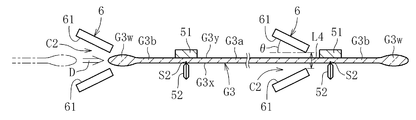
- a guide member 6 for guiding the lower end G3d of the glass original plate G3 is provided at a predetermined position on the transport path D of the transport device 4.
- the guide member 6 is provided immediately upstream of the formation position of each scribe line S2 in the first station ST1 and immediately upstream of each cutting position in the second station ST2.
- the height position of the guide member 6 can be adjusted as appropriate.
- the guide member 6 has a pair of guide surfaces 61 that are opposed to each other in the thickness direction of the glass original plate G3. Between the pair of guide surfaces 61, a guide gap C2 larger than the thickness of the side end portion G3w of the glass original plate G3 is formed. The facing distance between the pair of guide surfaces 61 having the guide gap C2 becomes smaller toward the downstream side. That is, the guide gap C2 is large at the upstream end of the guide member 6 and is small at the downstream end. While the glass original plate G3 is conveyed by the conveying device 4, the lower end portion G3d of the glass original plate G3 is passed through the guide gap C2 formed between the pair of guide surfaces 61 of the guide member 6.
- the scribe line S2 can be accurately formed on the glass original plate G3 at the first station ST1, or the glass original plate G3 can be accurately cleaved along the scribe line S2 at the second station ST2.
- the pair of guide surfaces 61 are preferably in contact with the glass original plate G3 within a range of 20 mm from the lower end of the glass original plate G3. That is, it is preferable that the pair of guide surfaces 61 does not contact the effective surface of the glass original plate G3.
- the pair of guide surfaces 61 are formed of a material that is slippery in order to prevent the glass original plate G3 from being damaged. Specifically, it is formed of, for example, ultra high molecular weight polyethylene.
- the inclination angle ⁇ of the pair of guide surfaces 61 with respect to the front and back surfaces of the glass original plate G3 is preferably 10 ° to 40 °.
- the facing distance L4 at the downstream ends of the pair of guide surfaces 61 is preferably 30 to 100 mm.
- a glass ribbon G2 is continuously formed by a forming apparatus 1 (forming step).
- the glass ribbon G2 is cut
- the delivery device 3 using the delivery device 3, the cut glass original plate G ⁇ b> 3 is delivered to the conveying device 4, and the glass original plate G ⁇ b> 3 is conveyed in a vertical posture by the conveying device 4 (conveying step).
- the conveying device 4 supports the upper end portion in a state where the movement of the side end portion G3w of the glass original plate G3 is regulated within the regulation gap C1 of the side end regulating portion 42 during the conveyance of the glass original plate G3.
- the upper end G3u of the glass original plate G3 is supported by the portion 41.
- the second cutting device 5 uses the product part G3a of the glass original plate G3 and the non-product part G3b including the side end part G3w.
- the boundary BL is cut in the vertical direction, and the non-product part is removed from the glass original plate G3 (second cutting step).
- the cut out product part G3a is conveyed to the subsequent process while being supported by the upper end support part 41.
- the glass ribbon is formed by the overflow down draw method, but is not limited thereto.
- a glass ribbon may be formed by a slot downdraw method, a redraw method, a float method, or the like.
- the thermal stress cleaving by a laser etc. may be used for the cutting of the glass ribbon G2 and / or the glass original plate G3. .
- the delivery apparatus 3 is abbreviate
- the glass plate of conveyance object is a side edge.
- the part may not have an ear part and may have a substantially uniform thickness in the width direction. That is, while the upper end portion of the glass plate not having the ear portion is supported by the upper end support portion 41 by the transport device 4, the side end portion is regulated within the regulation gap C ⁇ b> 1 of the side end portion regulation portion 42. A glass plate that does not have ears may be conveyed.
- the product part G3a is supported by the upper end support part 41 before and after cleaving, and the cleaved product part G3a is supported by the upper end part support part 41 to the subsequent process.
- the conveyance apparatus 4 is good also as a form which conveys the glass original plate G3 by 1 pitch between each station.
- the transport device 4 sequentially transfers and receives the glass original plate G3 to a gripping member (not shown) provided separately at each station (the transport device 4 moves one pitch ⁇ the glass master plate to the gripping member of the station).
- the conveying device 4 may return one pitch ⁇ the glass original plate G3 may be received by the upper end support part 41 from the gripping member of the station).
- the side edge part regulation part 42 is provided in the conveying apparatus 4 to the 2nd cutting device 5 from which the non-product part G3b is not removed.
Landscapes
- Chemical & Material Sciences (AREA)
- Engineering & Computer Science (AREA)
- Materials Engineering (AREA)
- Organic Chemistry (AREA)
- Mechanical Engineering (AREA)
- Re-Forming, After-Treatment, Cutting And Transporting Of Glass Products (AREA)
- Processing Of Stones Or Stones Resemblance Materials (AREA)
- Container, Conveyance, Adherence, Positioning, Of Wafer (AREA)
Abstract
ガラス板の製造方法は、ガラスリボンG2を連続成形する成形工程と、ガラスリボンG2を幅方向に切断し、ガラスリボンG2からガラス原板G3を切り出す第1の切断工程と、搬送装置4でガラス原板G3を縦姿勢で搬送する搬送工程と、搬送工程の中で、搬送装置4の搬送経路D上でガラス原板G3の製品部G3aとその側端部を含む非製品部G3bとの境界を上下方向に切断し、ガラス原板G3から非製品部G3bを除去する第2の切断工程とを備える。搬送装置4は、支持部41と、ガラス原板G3の側端部G3wの厚みよりも大きい規制隙間C1を有する規制部42とを備え、規制隙間C1内でガラス原板G3の側端部G3wを規制した状態で、支持部41でガラス原板G3の上端部G3uを支持する。
Description
本発明は、ガラス板の製造技術の改良に関する。
ガラス板を製造するための手法としては、オーバーフローダウンドロー法、スロットダウンドロー法、リドロー法に代表されるダウンドロー法を利用した手法や、フロート法を利用した手法が広く採用されるに至っている。これらの手法を利用したガラス板の製造工程の一例としては、以下のようなものが挙げられる。
まず、長尺なガラスリボンを連続的に成形する(例えば、特許文献1を参照)。この際、ガラスリボンの両側の側端部(幅方向の両端部)は、ガラスリボンの幅方向の中央部と比較して厚みが大きくなるのが通例である。ガラスリボンの両側の側端部の相対的に厚みが大きくなる部分は、耳部と呼ばれることがある。
次に、ガラスリボンを所定の長さ毎に幅方向に切断し、ガラスリボンからガラス板の元となるガラス原板を切り出す(例えば、特許文献2を参照)。ガラスリボンの側端部に耳部が形成される場合、ガラス原板の側端部にも耳部が残る。
その後、ガラス原板を切断し、ガラス原板から耳部を含んだ非製品部を除去することにより、ガラス原板から製品部を切り出す(例えば、特許文献3を参照)。この切り出された製品部に対して、研摩や洗浄等の各種工程を施すことで、最終的に製品となるガラス板が製造される。
ところで、オーバーフローダウンドロー法などのダウンドロー法を利用してガラス板を製造する場合、ガラスリボンは縦姿勢(例えば、鉛直姿勢など)の状態で成形される。そのため、省スペース化の観点等から、縦姿勢のガラスリボンからガラス原板を切り出すとともに、切り出されたガラス原板を縦姿勢のまま搬送し、その搬送経路上でガラス原板の非製品部を除去する場合がある。
しかしながら、ガラス原板から非製品部を除去するまでは、ガラス原板の両側の側端部には相対的に厚みの大きい耳部が残ったままである。そのため、ガラス原板を縦姿勢で搬送すると、ガラス原板から非製品部を除去するまでの区間で、側端部の重みでガラス原板が揺れたり折れ曲がったりするという事態が生じ得る。このような事態が生じると、ガラス原板の側端部及びその近傍に過度な曲げ応力が作用し、ガラス原板が搬送中に割れるおそれがある。このような問題の発生は、近年のガラス板の薄板化に伴ってより顕著になっている。これは、ガラス板の製品部を薄板化したとしても耳部は薄くならないため、ガラス原板において非製品部に含まれる側端部(耳部)と製品部との厚み差が大きくなり、側端部の重みが製品部に与える影響が大きくなるためである。
なお、上記の問題は、ダウンドロー法を利用した場合に限られるものではなく、フロート法を利用した場合であっても、縦姿勢のガラス原板の搬送を伴うときは同様に生じ得るものである。
本発明は、縦姿勢のガラス原板の搬送を伴う場合であっても、ガラス原板が搬送中に割れるのを確実に防止することを課題とする。
上記課題を解決するために創案された本発明に係るガラス板の製造方法は、ガラスリボンを連続成形する成形工程と、ガラスリボンを幅方向に切断し、ガラスリボンからガラス原板を切り出す切断工程と、搬送装置でガラス原板を縦姿勢で搬送する搬送工程とを備えたガラス板の製造方法であって、搬送装置が、支持部と、ガラス原板の側端部の厚みよりも大きい規制隙間を有する規制部とを備え、規制隙間内でガラス原板の側端部を規制した状態で、支持部でガラス原板の上端部を支持することを特徴とする。
このような構成によれば、ガラス原板の上端部を支持部で支持しつつ、ガラス原板の側端部を規制部の規制隙間内で規制することができる。すなわち、ガラス原板の側端部の動きは、規制隙間の範囲内に制限される。そのため、ガラス原板の側端部に揺れや折れ曲がりが生じにくくなる。したがって、ガラス原板を縦姿勢で搬送しても、ガラス原板が割れるのを確実に防止することができる。
ここで、ガラス原板の側端部を表裏両側から直接挟持することで、ガラス原板の揺れや折れ曲がりの問題を解決することも考えられるが、側端部の厚みは製造条件等によって変動する場合がある。そのため、ガラス原板の側端部を直接挟持する構成とした場合、ガラス原板の側端部が過度に押圧されて、却ってガラス原板に割れが生じやすくなることがある。そこで、本願発明は、このような知見に基づいて、ガラス原板の側端部を直接挟持する構成ではなく、上述のようにガラス原板の側端部の厚みよりも大きい規制隙間内で規制する構成とした。
上記の構成において、搬送装置は、ガラス原板を厚み方向に対向する表裏面に沿う幅方向に搬送してもよい。このようにすれば、搬送中にガラス原板に作用する空気抵抗が小さくなるため、ガラス原板の揺れや折れ曲がりをより確実に防止することができる。
上記の構成において、規制隙間内で、ガラス原板の側端部の上方部分のみを規制してもよい。
このようにすれば、支持部と規制部をガラス原板の上方部分に集めることできるので、搬送装置の構成をコンパクトにすることができる。
上記の構成において、搬送工程中に、搬送装置の搬送経路上でガラス原板の製品部とその側端部を含む非製品部との境界を上下方向に切断し、ガラス原板から非製品部を除去する第2の切断工程を更に備えていてもよい。
このようにすれば、側端部を含む非製品部の揺れや折れ曲がりを防止しつつ、ガラス原板から製品部を切り出すことができる。
上記の構成において、支持部が、ガラス原板の上端部のうち製品部の上端部のみを支持することが好ましい。
このようにすれば、支持部がガラス原板の上端部のうち非製品部の上端部を支持しないため、ガラス原板から非製品部を切断除去する際に、支持部による支持が邪魔になることがない。また、非製品部を切断後は、支持部で製品部を支持した状態のまま、製品部を後続の工程に搬送することもできる。
上記の構成において、搬送装置の搬送経路上の所定位置に、ガラス原板の側端部の厚みよりも大きいガイド隙間を有するガイド部材を設け、搬送装置によってガラス原板を搬送しながら、所定位置でガラス原板の下端部をガイド隙間に通過させるようにしてもよい。
このようにすれば、搬送装置とは別のガイド部材のガイド隙間によって、搬送経路上の所定位置でガラス原板の下端部が案内される。そのため、ガラス原板の下端部の位置を搬送中に修正することができる。
上記の構成において、ガイド部材が、ガラス原板の厚み方向に対向する一対のガイド面を有し、一対のガイド面間がガイド隙間とされるとともに、一対のガイド面の対向間隔が、搬送方向の下流側に向かうに連れて小さくなっていてもよい。
このようにすれば、ガラス原板の下端部を一対のガイド面の間に通過させるだけで、ガラス原板の下端部の位置を無理なく確実に修正することができる。
上記の構成において、第2の切断工程は、ガラス原板の製品部と非製品部の境界に上下方向にスクライブ線を形成するための第1のステーションと、第1のステーションの搬送方向の下流側に設けられ、スクライブ線に沿ってガラス原板を割断するための第2のステーションとを有し、ガイド部材は、第1のステーション及び第2のステーションの少なくとも一方に配置されていてもよい。
このようにすれば、スクライブ線を形成する第1のステーションと、スクライブ線に沿ってガラス原板を割断する第2のステーションの少なくとも一方で、ガラス原板の下端部がガイド部材によって案内される。そのため、ガイド部材を設けた側のステーションにおいて、ガラス原板の位置決めを確実に行うことができる。したがって、ガラス原板に対して、ガイド部材を設けた側のステーションに対応する加工(スクライブ線の形成及び/又は割断)を精度よく施すことができる。
上記課題を解決するために創案された本発明に係るガラス板の製造装置は、ガラスリボンを連続成形する成形装置と、ガラスリボンを幅方向に切断し、ガラスリボンからガラス原板を切り出す切断装置と、ガラス原板を縦姿勢で搬送する搬送装置とを備えたガラス板の製造装置であって、搬送装置が、ガラス原板の上端部を支持する支持部と、ガラス原板の側端部の厚みよりも大きい規制隙間を有し、規制隙間内でガラス原板の側端部を規制する規制部とを備えていることを特徴とする。このような構成によれば、既に述べた対応する構成と同様の効果を享受することができる。
上記の構成において、搬送装置の搬送経路上でガラス原板の製品部とその側端部を含む非製品部との境界を上下方向に切断し、ガラス原板から非製品部を除去する第2の切断装置を更に備えていてもよい。このような構成によれば、既に述べた対応する構成と同様の効果を享受することができる。
上記課題を解決するために創案された本発明に係るガラス板の搬送装置は、縦姿勢のガラス板を搬送するガラス板の搬送装置であって、ガラス板の上端部を支持する支持部と、ガラス板の側端部の厚みよりも大きい規制隙間を有し、規制隙間内でガラス板の側端部を規制する規制部とを備えていることを特徴とする。このような構成によれば、既に述べた対応する構成と同様の効果を享受することができる。
以上のように本発明によれば、縦姿勢のガラス原板の搬送を伴う場合であっても、ガラス原板が搬送中に割れるのを確実に防止することができる。
以下、本発明に係る一実施形態を添付図面に基づいて説明する。
図1~図6に示すように、ガラス板の製造装置は、ガラスリボンG2を成形する成形装置1(図1を参照)と、ガラスリボンG2からガラス原板G3を切り出す第1の切断装置2(図1を参照)と、第1の切断装置2からガラス原板G3を受け取る受け渡し装置3(図1を参照)と、受け渡し装置3からガラス原板G3を受け取って搬送する搬送装置4(図2参照)と、搬送装置4で搬送中のガラス原板G3から不要部分を切断除去する第2の切断装置5(図4を参照)とを備えている。
図1に示すように、成形装置1は、ガラスリボンG2を成形する成形炉11と、ガラスリボンG2を徐冷(アニール処理)する徐冷炉12と、ガラスリボンG2を室温付近まで冷却する冷却炉13と、成形炉11、徐冷炉12及び冷却炉13のそれぞれの内部空間で上下複数段に設けられたローラ対14とを備えている。
成形炉11の内部空間には、オーバーフローダウンドロー法により溶融ガラスG1からガラスリボンG2を成形する成形体15が配置されている。成形体15に供給された溶融ガラスG1は成形体15の頂部15aから溢れ出るようになっており、その溢れ出た溶融ガラスG1が成形体15の断面楔状を呈する両側面15bを伝って下端で合流することで、板状のガラスリボンG2が連続的に成形されるようになっている。成形されるガラスリボンG2は、縦姿勢(好ましくは鉛直姿勢)である。
徐冷炉12の内部空間は、下方に向かって所定の温度勾配を有している。縦姿勢のガラスリボンG2は、徐冷炉12の内部空間を下方に向かって移動するに連れて、温度が低くなるように徐冷される。これに伴い、ガラスリボンG2の内部歪が除去される。徐冷炉12の内部空間の温度勾配は、例えば、徐冷炉12の内面に設けた加熱装置などの温度調整装置により調整することができる。ここで、徐冷炉12の下方でガラスリボンG2を大気に解放し、冷却炉13を省略してもよい。
複数のローラ対14は、縦姿勢のガラスリボンG2の両側の側端部を表裏両側から挟持するようになっている。なお、例えば徐冷炉12の内部空間などでは、複数のローラ対14の中に、ガラスリボンG2の側端部を挟持しないものが含まれていてもよい。換言すれば、ローラ対14の対向間隔をガラスリボンG2の側端部の厚みよりも大きくし、ローラ対14の間をガラスリボンG2が通過するようにしてもよい。この実施形態では、ガラスリボンG2を挟んで対向するローラ対14を構成する個々のローラは、炉外に延びた回転軸によって支持された片持ちローラによって構成されている。
ここで、この実施形態では、成形装置1によって製造されたガラスリボンG2の両側の側端部は、成形過程の収縮等の影響により、幅方向の中央部に比べて厚みが大きい。すなわち、ガラスリボンG2の両側の側端部のそれぞれは、いわゆる耳部となる。
図1に示すように、第1の切断装置2は、成形装置1の下方で縦姿勢のガラスリボンG2を所定の長さ毎に幅方向に切断することにより、ガラスリボンG2からガラス原板G3を順次切り出すように構成されている。ここで、幅方向は、ガラスリボンG2の長手方向と直交する方向であり、この実施形態では実質的に水平方向と一致する。
第1の切断装置2は、成形装置1から降下してきた縦姿勢のガラスリボンG2の表面G2x上を走行することで、ガラスリボンG2の幅方向に沿ってスクライブ線S1を形成するホイールカッター(図示省略)と、スクライブ線S1が形成された領域に裏面G2y側から当接する裏面支持部21と、切り出し対象のガラス原板G3に対応する部分のガラスリボンG2を支持した状態で、スクライブ線S1及びその近傍に曲げ応力を作用させるための動作を行う側端部支持部22とを備えている。ここで、表面G2x及び裏面G2yは、互いに厚み方向で対向する主表面を意味するもので、ガラスリボンG2のいずれの主表面を表面G2x(又は裏面G2y)としてもよい。これは、後述するガラス原板G3の表裏面についても同様である。
ホイールカッターは、降下中のガラスリボンG2に追従降下しつつ、ガラスリボンG2の幅方向の全幅又は一部にスクライブ線S1を形成する構成となっている。この実施形態では、相対的に厚みが大きくなるガラスリボンG2の側端部にも幅方向にスクライブ線S1が形成される。なお、スクライブ線S1はレーザーの照射等によって形成してもよい。
裏面支持部21は、ガラスリボンG2の幅方向に沿って長尺となるように形成されており、降下中のガラスリボンG2に追従降下しつつ、ガラスリボンG2の全幅又は一部と当接する構成となっている。
側端部支持部22は、ガラスリボンG2の両側の側端部を表裏両側から挟持するチャック機構により構成されている。この実施形態では、側端部支持部22は、ガラスリボンG2の両側の側端部のそれぞれにおいて、ガラスリボンG2の長手方向に間隔を置いて複数設けられている。一方側の側端部に設けられた複数の側端部支持部22は、これら全てが同一のアーム(図示省略)によって保持されている。また同様に、他方側の側端部に設けられた複数の側端部支持部22も、これら全てが同一のアーム(図示省略)によって保持されている。そして、各々のアームの動作により、複数の側端部支持部22が降下中のガラスリボンG2に追従降下しつつ、矢印Aで示すように、支持したガラスリボンG2を裏面支持部21を支点として湾曲させるための動作を行う。これにより、スクライブ線S1及びその近傍に曲げ応力を付与し、ガラスリボンG2をスクライブ線S1に沿って幅方向に割断する。この割断の結果、ガラスリボンG2からガラス原板G3が切り出される。なお、側端部支持部22は、挟持する支持形態に限らず、ガラスリボンG2(又はガラス原板G3)の表裏面のいずれか一方の面のみを負圧吸着によって支持するものであってもよい。
側端部支持部22は、切り出されたガラス原板G3をアームの移動に伴って搬送経路Bに沿って第1の位置P1まで搬送した後、受け渡し装置3にガラス原板G3を受け渡すことが可能となっている。受け渡し後には、側端部支持部22が、ガラス原板G3における側端部の支持を解除するとともに、ガラスリボンG2から次のガラス原板G3を切り出すために、アームの移動に伴って切り出しを開始する前の位置に戻る。
図1に示すように、受け渡し装置3は、ガラス原板G3を吊り下げ支持する上端部支持部31を備えている。
上端部支持部31は、ガラス原板G3の上端部G3uを表裏両側から挟持するチャック機構から構成されている。上端部支持部31は、第1の位置P1において、第1の切断装置2の側端部支持部22から縦姿勢のガラス原板G3を受け取った後、搬送経路C(図示例では水平方向)に沿って、縦姿勢のガラス原板G3を第2の位置P2まで厚み方向(表裏面に垂直な方向)に搬送するように構成されている。なお、上端部支持部31は、挟持する支持形態に限らず、ガラス原板G3の表裏面のいずれか一方の面のみを負圧吸着によって支持するものであってもよい。
図2に示すように、搬送装置4は、ガラス原板G3を吊り下げ支持する上端部支持部41と、ガラス原板G3の幅方向両側のそれぞれで側端部G3wを規制する側端部規制部42とを備えている。ここで、第2の位置P2において、ガラス原板G3は、製品部G3aと、側端部G3wを含む非製品部(不要部分)G3bとの境界BLが上下方向に向くように配置されている。非製品部G3bは、製品部G3aの幅方向両側にそれぞれ形成される。上端部支持部41は、ガラス原板G3の製品部G3aを支持し、側端部規制部42は、ガラス原板G3の非製品部G3bに含まれる少なくとも側端部G3wを規制する。この実施形態では、非製品部G3bに含まれる側端部G3wは、製品部G3aに比べて厚みが大きい(図3を参照)。
上端部支持部41は、ガラス原板G3の上端部を表裏両側から挟持するチャック機構により構成されている。上端部支持部41は、ガラス原板G3の上端から20mm以内の範囲でガラス原板G3を挟持することが好ましい。すなわち、上端部支持部41は、ガラス原板G3の額縁状の周縁部を除く中央側領域に形成される有効面(品質が保証された部分)には接触しないようにすることが好ましい。
上端部支持部41は、第2の位置P2において、受け渡し装置3の上端部支持部31から縦姿勢のガラス原板G3を受け取った後、縦姿勢のガラス原板G3を搬送経路D(図2では水平方向)に沿って下流側へと搬送するように構成されている。図示は省略するが、受け渡し装置3の上端部支持部31と、搬送装置4の上端部支持部41とは、互いにガラス原板G3を支持する位置が異なる。第2の位置P2では、まず、受け渡し装置3の上端部支持部31でガラス原板G3が支持されており、その状態で、搬送装置4の上端部支持部41でガラス原板G3の異なる位置が支持される。その後、搬送装置4の上端部支持部41でガラス原板G3を支持した状態で、受け渡し装置3の上端部支持部31によるガラス原板G3の支持が解除される。これにより、第2の位置P2で、受け渡し装置3から搬送装置4にガラス原板G3が受け渡される。なお、受け渡し装置3は、搬送装置4にガラス原板G3を受け渡した後、第2の位置P2から第1の位置P1へと戻る。
搬送装置4は、レール43と、レール43に沿ってスライド移動する第1の移動体44とを備えており、ガラス原板G3の幅方向に間隔を置いて配置された複数(図示例は2つ)の上端部支持部41が第1の移動体44に取り付けられている。この実施形態では、複数の上端部支持部41が1つの第1の移動体44に取り付けられ、第1の移動体44の移動に伴って複数の上端部支持部41が一体的にレール43に沿って移動するようになっている。レール43はガラス原板G3の幅方向に沿って設けられているため、ガラス原板G3は表裏面に沿う幅方向に搬送される。なお、ガラス原板G3を厚み方向に搬送するようにしてもよい。また、上端部支持部41は、ガラス原板G3の表裏面のいずれか一方の面のみを負圧吸着によって支持するものであってもよい。さらに、複数の上端部支持部41は、互いに接近および離反可能なように、それぞれ独立した移動体に取り付けられていてもよい。このようにすれば、ガラス原板G3の大きさが変更された場合などでも支持位置の調整が簡単になったり、ガラス原板G3に幅方向に張力を付与することができたりする等の利点がある。
図3に示すように、側端部規制部42は、ガラス原板G3の側端部G3wの厚みよりも大きい規制隙間C1を有し、規制隙間C1内でガラス原板G3の側端部G3wを規制するようになっている。すなわち、側端部規制部42は、規制隙間C1内に配置されたガラス原板G3を直接挟持しない。この実施形態では、ガラス原板G3の側端部G3wの上方部分のみが規制隙間C1内に配置される。この場合、側端部規制部42は、ガラス原板G3の上端から20mm以内の範囲に配置されることが好ましい。すなわち、側端部規制部42は、ガラス原板G3の有効面には接触しないようにすることが好ましい。なお、側端部規制部42は、ガラス原板G3の側端部G3wの上下方向に間隔を置いて複数(例えば、上方部分、中央部分および下方部分の3箇所)配置されていてもよい。
側端部規制部42は、開閉動作が可能な一対のアーム42aを備えており、閉状態で一対のアーム42aの間に規制隙間C1が形成されるようになっている。すなわち、側端部規制部42は、ガラス原板G3を直接挟持しないという点以外はチャック機構に準ずる構成を備えている。第2の位置P2において、受け渡し装置3の上端部支持部31から搬送装置4の上端部支持部41へとガラス原板G3を受け渡す間に、開状態の側端部規制部42がガラス原板G3の側端部G3wに接近した後に閉状態となり、ガラス原板G3の側端部G3wが規制隙間C1内に配置される(図2及び図3を参照)。なお、側端部規制部42は、ガラス原板G3の側端部G3wを規制する規制隙間C1を有していれば、上述のような開閉機構を有していなくてもよい。
図2に示すように、搬送装置4は、第1の移動体44と同じレール43に沿ってスライド移動する第2の移動体45とを備えており、側端部規制部42が第2の移動体45に取り付けられている。この実施形態では、第2の移動体45は第1の移動体44の動きに同期するようになっている。そのため、上端部支持部41と側端部規制部42の相対的な位置関係は変わらず、上端部支持部41によって支持されたガラス原板G3が移動しても、側端部規制部42はガラス原板G3に追従するようになっている。なお、側端部規制部42は、上端部支持部41と共通の移動体に取り付けられていてもよい。
ここで、図3に示すように、側端部規制部42のアーム42aのガラス原板G3と対面する部分には、ガラス原板G3が揺れて接触した場合にガラス原板G3に傷付くのを防止するために、ゴムなどの弾性体42bが設けられている。規制隙間C1のガラス原板G3の厚み方向における間隔L1は、5~10mmであることが好ましい。規制隙間C1のガラス原板G3の幅方向における深さL2は、50~100mmであることが好ましい。規制隙間C1内に配置されるガラス原板G3の幅方向寸法L3は、30~70mmであることが好ましい。
以上のように構成された側端部規制部42の規制隙間C1内で、ガラス原板G3の側端部G3wの動きを規制すると、ガラス原板G3の搬送中にガラス原板G3の側端部G3wに揺れや折れ曲がりが生じにくくなる。したがって、ガラス原板G3を縦姿勢で搬送しても、側端部G3wを含む非製品部G3bを切除する前に、ガラス原板G3が割れるのを確実に防止することができる。
図4に示すように、第2の切断装置5は、ガラス原板G3の製品部G3aと非製品部G3bの境界BLに沿って上下方向にスクライブ線S2を形成するための第1のステーションST1と、第1のステーションST1の下流側に設けられ、スクライブ線S2に沿ってガラス原板G3を割断するための第2のステーションST2とを備えている。この実施形態では、搬送装置4によって搬送されるガラス原板G3は、第1のステーションST1と第2のステーションST2とで一時停止し、各々のステーションで加工処理が行われる。
図4及び図5に示すように、第2の切断装置5は、第1のステーションST1において、ガラス原板G3のスクライブ線S2が形成される領域に裏面G3y側から当接する裏面支持部51と、スクライブ線S2をガラス原板G3の表面G3x側に形成するホイールカッター52とを備えている。ホイールカッター52は、ガラス原板G3の上下方向の全域又は一部にスクライブ線S2を形成するように構成されている。この実施形態では、ガラス原板G3の上端部G3uと下端部G3dを除く上下方向の一部にスクライブ線S2が形成される。なお、スクライブ線S2はレーザーの照射等によって形成してもよい。
図4及び図6に示すように、第2の切断装置5は、第2のステーションST2において、スクライブ線S2と間隔を置いてスクライブ線S2と平行に製品部G3aの裏面G3y側に当接する裏面支持部53と、スクライブ線S2と間隔を置いてスクライブ線S2と平行に非製品部G3bの表面G3x側に当接する押圧部54とを備えている。
この実施形態では、裏面支持部53及び押圧部54は、ガラス原板G3に当接する面が平面で形成された板状体(定盤)である。なお、裏面支持部53及び押圧部54は、当接面が曲面で形成された丸棒状体などであってもよい。
押圧部54は、非製品部G3bを裏面G3y側に押し込むことで、ガラス原板G3を裏面支持部53を支点として湾曲させる(図6の矢印Eを参照)。これにより、スクライブ線S2及びその近傍に曲げ応力を付与し、ガラス原板G3をスクライブ線S2に沿って上下方向に割断する。この割断の結果、ガラス原板G3から非製品部G3bが除去され、製品部G3aが切り出される。この際、押圧部54によるガラス原板G3の押し込み動作を阻害しないように、側端部規制部42は開状態となってガラス原板G3から離れている(図4を参照)。詳細には、第2のステーションST2までガラス原板G3の側端部G3wの動きを側端部規制部42で規制しながらガラス原板G3を搬送した後、押圧部54でガラス原板G3を押圧する前に、側端部規制部42をガラス原板G3から離して側端部G3wの規制を解除する。
この実施形態では、製品部G3aは、割断前後において上端部支持部41によって支持されており、割断された製品部G3aは、上端部支持部41によって支持された状態で後続の工程へと搬送されるようになっている。上端部支持部41及び側端部規制部42は、予め決められた後続の工程(例えば、検査など)まで移動した後、受け渡し装置3からガラス原板G3を受け取る第2の位置P2まで戻る。
一方、非製品部G3bは、割断後に支持しなければ、製品部G3aの近傍で落下回収されることになる。なお、製品部G3aの近傍での非製品部G3bの落下を防止するために、割断前後で非製品部G3bを支持し、製品部G3aから離れた位置で非製品部G3bを回収するようにしてもよい。非製品部G3bの支持には、例えば、ロボットアームの先端に非製品部G3bの裏面G3yを吸着可能なバキュームカップを備えたものなどが利用できる。
図4に示すように、この実施形態では、搬送装置4の搬送経路D上の所定位置には、ガラス原板G3の下端部G3dを案内するガイド部材6が設けられている。詳細には、ガイド部材6は、第1のステーションST1における各スクライブ線S2の形成位置の直上流、第2のステーションST2における各割断位置の直上流にそれぞれ設けられている。ガイド部材6の高さ位置は適宜調整可能となっている。
図5及び図6に示すように、ガイド部材6は、ガラス原板G3の厚み方向に対向する一対のガイド面61を有する。一対のガイド面61間には、ガラス原板G3の側端部G3wの厚みよりも大きいガイド隙間C2が形成されている。このガイド隙間C2を有する一対のガイド面61の対向間隔は、下流側に向かうに連れて小さくなっている。すなわち、ガイド隙間C2は、ガイド部材6の上流端において大きく、その下流端において小さくなっている。搬送装置4によってガラス原板G3を搬送しながら、ガラス原板G3の下端部G3dをガイド部材6の一対のガイド面61の間に形成されるガイド隙間C2に通過させる。これにより、ガラス原板G3の上端部G3uのみを支持している場合であっても、ガラス原板G3の下端部G3dの位置を正しく修正することができる。そのため、第1のステーションST1でガラス原板G3に正確にスクライブ線S2を形成したり、第2のステーションST2でガラス原板G3をスクライブ線S2に沿って正確に割断したりすることができる。
一対のガイド面61は、ガラス原板G3の下端から20mmの範囲内でガラス原板G3と接触することが好ましい。すなわち、一対のガイド面61は、ガラス原板G3の有効面には接触しないようにすることが好ましい。一対のガイド面61は、ガラス原板G3が傷付くのを防止するために、滑りのよい材質で形成されている。具体的には、例えば超高分子量ポリエチレンにより形成される。一対のガイド面61のガラス原板G3の表裏面に対する傾斜角度θは、10°~40°であることが好ましい。一対のガイド面61の下流端における対向間隔L4は、30~100mmであることが好ましい。
次に、以上のように構成された板ガラスの製造装置を用いた板ガラスの製造方法を説明する。
まず、図1に示すように、成形装置1によってガラスリボンG2を連続成形する(成形工程)。次に、成形装置1の下方位置において、第1の切断装置2によってガラスリボンG2を幅方向に切断し、ガラスリボンG2からガラス原板G3を切り出す(第1の切断工程)。その後、受け渡し装置3を用いて、図2に示すように、切り出されたガラス原板G3を搬送装置4に受け渡すとともに、搬送装置4でガラス原板G3を縦姿勢で搬送する(搬送工程)。図3に示すように、搬送装置4は、ガラス原板G3の搬送中、側端部規制部42の規制隙間C1内でガラス原板G3の側端部G3wの動きを規制した状態で、上端部支持部41でガラス原板G3の上端部G3uを支持する。そして、図4~図6に示すように、搬送装置4の搬送経路D上で、第2の切断装置5によってガラス原板G3の製品部G3aとその側端部G3wを含む非製品部G3bとの境界BLを上下方向に切断し、ガラス原板G3から非製品部を除去する(第2の切断工程)。切り出された製品部G3aは、上端部支持部41によって支持された状態で、後続の工程へと搬送される。
以上、本発明の実施形態に係る板ガラスの製造装置及びその製造方法について説明したが、本発明の実施の形態はこれに限定されるわけではなく、本発明の要旨を逸脱しない範囲で種々変更を施すことが可能である。
例えば、上記の実施形態では、ガラスリボンをオーバーフローダウンドロー法により成形する構成となっているが、これには限定されない。オーバーフローダウンドロー法の他、スロットダウンドロー法、リドロー法、フロート法等によってガラスリボンを成形する構成としてもよい。
また、上記の実施形態では、ガラスリボンG2及びガラス原板G3をスクライブ割断する場合を説明したが、ガラスリボンG2及び/又はガラス原板G3の切断には、レーザー等による熱応力割断を用いてもよい。
また、上記の実施形態では、受け渡し装置3を用いる場合を説明したが、受け渡し装置3を省略し、第1の切断装置2の側端部支持部22で支持されたガラス原板G3を、搬送装置4の上端部支持部41に直接受け渡すようにしてもよい。
また、上記の実施形態では、搬送対象となるガラス原板G3の側端部G3wが、相対的に厚みが大きくなる耳部から形成される場合を説明したが、搬送対象のガラス板は、側端部において耳部を有さず、幅方向で厚みが実質的に均一なものであってもよい。すなわち、搬送装置4によって、耳部を有さないガラス板の上端部を上端部支持部41で支持しつつ、その側端部を側端部規制部42の規制隙間C1内で規制した状態で、耳部を有さないガラス板を搬送してもよい。
また、上記の実施形態では、製品部G3aは、割断前後において上端部支持部41によって支持されており、割断された製品部G3aは、上端部支持部41によって支持された状態で後続の工程へと搬送されるようになっているが、これには限定されない。例えば、搬送装置4は、各ステーション間で1ピッチずつガラス原板G3を搬送する形態としてもよい。この場合、搬送装置4は、各ステーションに別途備えつけられている図示しない把持部材にガラス原板G3の受け渡しと受け取りを順々に行う形態(搬送装置4が1ピッチ移動→ステーションの把持部材にガラス原板G3を受け渡し→搬送装置4が1ピッチ戻る→ステーションの把持部材からガラス原板G3を上端部支持部41が受け取る)でもよい。この場合、側端部規制部42は、非製品部G3bが除去されていない第2の切断装置5までの搬送装置4に設けられていることが好ましい。
1 成形装置
11 成形炉
12 徐冷炉
13 冷却炉
14 ローラ対
15 成形体
2 第1の切断装置
21 裏面支持部
22 側端部支持部
3 受け渡し装置
31 上端部支持部
4 搬送装置
41 上端部支持部
42 側端部規制部
43 レール
44 第1の移動体
45 第2の移動体
5 第2の切断装置
51 裏面支持部
52 ホイールカッター
53 裏面支持部
54 押圧部
6 ガイド部材
61 ガイド面
C1 規制隙間
C2 ガイド隙間
G1 溶融ガラス
G2 ガラスリボン
G3 ガラス原板
S1 スクライブ線
S2 スクライブ線
11 成形炉
12 徐冷炉
13 冷却炉
14 ローラ対
15 成形体
2 第1の切断装置
21 裏面支持部
22 側端部支持部
3 受け渡し装置
31 上端部支持部
4 搬送装置
41 上端部支持部
42 側端部規制部
43 レール
44 第1の移動体
45 第2の移動体
5 第2の切断装置
51 裏面支持部
52 ホイールカッター
53 裏面支持部
54 押圧部
6 ガイド部材
61 ガイド面
C1 規制隙間
C2 ガイド隙間
G1 溶融ガラス
G2 ガラスリボン
G3 ガラス原板
S1 スクライブ線
S2 スクライブ線
Claims (11)
- ガラスリボンを連続成形する成形工程と、前記ガラスリボンを幅方向に切断し、前記ガラスリボンからガラス原板を切り出す切断工程と、搬送装置で前記ガラス原板を縦姿勢で搬送する搬送工程とを備えたガラス板の製造方法であって、
前記搬送装置が、支持部と、前記ガラス原板の前記側端部の厚みよりも大きい規制隙間を有する規制部とを備え、
前記規制隙間内で前記ガラス原板の前記側端部を規制した状態で、前記支持部で前記ガラス原板の上端部を支持することを特徴とするガラス板の製造方法。 - 前記搬送装置が、前記ガラス原板を厚み方向に対向する表裏面に沿う幅方向に搬送することを特徴とする請求項1に記載のガラス板の製造方法。
- 前記規制隙間内で、前記ガラス原板の前記側端部の上方部分のみを規制することを特徴とする請求項1又は2に記載のガラス板の製造方法。
- 前記搬送工程中に、前記搬送装置の搬送経路上で前記ガラス原板の製品部とその側端部を含む非製品部との境界を上下方向に切断し、前記ガラス原板から前記非製品部を除去する第2の切断工程を更に備えていることを特徴とする請求項1~3のいずれか1項に記載のガラス板の製造方法。
- 前記支持部が、前記ガラス原板の前記上端部のうち前記製品部の上端部のみを支持することを特徴とする請求項4に記載のガラス板の製造方法。
- 前記搬送装置の前記搬送経路上の所定位置に、前記ガラス原板の前記側端部の厚みよりも大きいガイド隙間を有するガイド部材を設け、
前記搬送装置によって前記ガラス原板を搬送しながら、前記所定位置で前記ガラス原板の下端部を前記ガイド隙間に通過させることを特徴とする請求項4又は5に記載のガラス板の製造方法。 - 前記ガイド部材が、前記ガラス原板の厚み方向に対向する一対のガイド面を有し、
前記一対のガイド面間が前記ガイド隙間とされるとともに、前記一対のガイド面の対向間隔が、搬送方向の下流側に向かうに連れて小さくなっていることを特徴とする請求項6に記載のガラス板の製造方法。 - 前記第2の切断工程は、前記ガラス原板の前記製品部と前記非製品部の境界に上下方向にスクライブ線を形成するための第1のステーションと、前記第1のステーションの搬送方向の下流側に設けられ、前記スクライブ線に沿って前記ガラス原板を割断するための第2のステーションとを有し、
前記ガイド部材は、前記第1のステーション及び前記第2のステーションの少なくとも一方に配置されていることを特徴とする請求項6又は7に記載のガラス板の製造方法。 - ガラスリボンを連続成形する成形装置と、前記ガラスリボンを幅方向に切断し、前記ガラスリボンからガラス原板を切り出す切断装置と、前記ガラス原板を縦姿勢で搬送する搬送装置とを備えたガラス板の製造装置であって、
前記搬送装置が、前記ガラス原板の上端部を支持する支持部と、前記ガラス原板の側端部の厚みよりも大きい規制隙間を有し、前記規制隙間内で前記ガラス原板の前記側端部を規制する規制部とを備えていることを特徴とするガラス板の製造装置。 - 前記搬送装置の搬送経路上で前記ガラス原板の製品部とその側端部を含む非製品部との境界を上下方向に切断し、前記ガラス原板から前記非製品部を除去する第2の切断装置を更に備えていることを特徴とする請求項9に記載のガラス板の製造装置。
- 縦姿勢のガラス板を搬送するガラス板の搬送装置であって、
前記ガラス板の上端部を支持する支持部と、前記ガラス板の側端部の厚みよりも大きい規制隙間を有し、前記規制隙間内で前記ガラス板の前記側端部を規制する規制部とを備えていることを特徴とするガラス板の搬送装置。
Priority Applications (2)
| Application Number | Priority Date | Filing Date | Title |
|---|---|---|---|
| KR1020187029961A KR102246032B1 (ko) | 2016-05-18 | 2017-04-20 | 유리판의 제조 방법 및 그 제조 장치, 그리고 유리판의 반송 장치 |
| CN201780027886.0A CN109071310B (zh) | 2016-05-18 | 2017-04-20 | 玻璃板的制造方法及其制造装置 |
Applications Claiming Priority (2)
| Application Number | Priority Date | Filing Date | Title |
|---|---|---|---|
| JP2016099546A JP6631838B2 (ja) | 2016-05-18 | 2016-05-18 | ガラス板の製造方法及びその製造装置、並びにガラス板の搬送装置 |
| JP2016-099546 | 2016-05-18 |
Publications (1)
| Publication Number | Publication Date |
|---|---|
| WO2017199681A1 true WO2017199681A1 (ja) | 2017-11-23 |
Family
ID=60325157
Family Applications (1)
| Application Number | Title | Priority Date | Filing Date |
|---|---|---|---|
| PCT/JP2017/015877 Ceased WO2017199681A1 (ja) | 2016-05-18 | 2017-04-20 | ガラス板の製造方法及びその製造装置、並びにガラス板の搬送装置 |
Country Status (4)
| Country | Link |
|---|---|
| JP (1) | JP6631838B2 (ja) |
| KR (1) | KR102246032B1 (ja) |
| CN (1) | CN109071310B (ja) |
| WO (1) | WO2017199681A1 (ja) |
Cited By (9)
| Publication number | Priority date | Publication date | Assignee | Title |
|---|---|---|---|---|
| WO2019097940A1 (ja) * | 2017-11-15 | 2019-05-23 | 日本電気硝子株式会社 | ガラス板の製造方法及びその製造装置 |
| CN112912351A (zh) * | 2018-09-19 | 2021-06-04 | 康宁公司 | 玻璃片处理设备及方法 |
| CN113195182A (zh) * | 2018-12-21 | 2021-07-30 | 日本电气硝子株式会社 | 玻璃板制造方法以及玻璃板制造装置 |
| JP2021519251A (ja) * | 2018-03-22 | 2021-08-10 | コーニング インコーポレイテッド | ガラスシートを検査する方法、ガラスシートを製造する方法、およびガラス製造装置 |
| GB2599776A (en) * | 2020-08-11 | 2022-04-13 | Gs Mr Glass And Stone Machinery And Robotics Uk & Ireland Ltd | Sheet handling process |
| WO2022130750A1 (ja) * | 2020-12-18 | 2022-06-23 | 日本電気硝子株式会社 | 板ガラスの製造方法及び割断装置 |
| WO2023218966A1 (ja) * | 2022-05-10 | 2023-11-16 | 日本電気硝子株式会社 | ガラス板の製造方法、ガラス板及びガラス板梱包体 |
| WO2023218961A1 (ja) * | 2022-05-10 | 2023-11-16 | 日本電気硝子株式会社 | ガラス板の製造方法、ガラス板及びガラス板梱包体 |
| WO2024018930A1 (ja) * | 2022-07-22 | 2024-01-25 | 日本電気硝子株式会社 | ディスプレイ用ガラス原板、ガラス原板の製造方法、及びガラス原板梱包体 |
Families Citing this family (6)
| Publication number | Priority date | Publication date | Assignee | Title |
|---|---|---|---|---|
| JP7276654B2 (ja) | 2019-04-22 | 2023-05-18 | 日本電気硝子株式会社 | ガラス板の製造装置および製造方法 |
| JP7366344B2 (ja) * | 2019-10-09 | 2023-10-23 | 日本電気硝子株式会社 | ガラス板の製造方法及びその製造装置 |
| JP2022075174A (ja) * | 2020-11-06 | 2022-05-18 | 日本電気硝子株式会社 | 板ガラスの製造方法及びその製造装置 |
| CN112960898A (zh) * | 2021-03-02 | 2021-06-15 | 甘肃光轩高端装备产业有限公司 | 玻璃分离设备和方法 |
| CN220485542U (zh) | 2021-04-13 | 2024-02-13 | 日本电气硝子株式会社 | 玻璃板的制造装置 |
| JP2024024968A (ja) * | 2022-08-10 | 2024-02-26 | 日本電気硝子株式会社 | ガラス板の製造装置及びガラス板の製造方法 |
Citations (7)
| Publication number | Priority date | Publication date | Assignee | Title |
|---|---|---|---|---|
| JPS5936056A (ja) * | 1982-08-18 | 1984-02-28 | Nippon Sheet Glass Co Ltd | 板材運搬具の板材位置決め機構 |
| JPH11246046A (ja) * | 1998-03-02 | 1999-09-14 | Sony Corp | 基板搬送装置 |
| JP3135359U (ja) * | 2007-07-02 | 2007-09-13 | ホーエイテック株式会社 | ハンドリング装置 |
| JP2013187389A (ja) * | 2012-03-08 | 2013-09-19 | Nippon Electric Glass Co Ltd | ガラス基板の搬送装置及び搬送方法 |
| WO2014139594A1 (en) * | 2013-03-15 | 2014-09-18 | Applied Materials, Inc. | Carrier for a substrate and method for carrying a substrate |
| JP2014205579A (ja) * | 2013-04-10 | 2014-10-30 | 日本電気硝子株式会社 | 保持部付ガラス基板、ガラス基板の熱処理方法、及びガラス基板支持ユニット |
| JP2016026968A (ja) * | 2014-06-30 | 2016-02-18 | AvanStrate株式会社 | ガラス板製造方法およびガラス板製造装置 |
Family Cites Families (8)
| Publication number | Priority date | Publication date | Assignee | Title |
|---|---|---|---|---|
| DE701065C (de) * | 1938-03-18 | 1941-01-08 | Libbey Owens Ges Fuer Maschine | Vorrichtung zum Halten von Flachglasplatten beim Haerten |
| JP2006056610A (ja) * | 2004-08-17 | 2006-03-02 | Kyokuhei Glass Kako Kk | ガラス基板の移送用把持具および該把持具を用いたガラス基板搬送用ボックスへの収納方法 |
| JP2014005170A (ja) | 2012-06-25 | 2014-01-16 | Nippon Electric Glass Co Ltd | ガラス板の製造方法 |
| JP5867725B2 (ja) | 2012-07-27 | 2016-02-24 | 日本電気硝子株式会社 | 板ガラスの製造方法及び製造装置 |
| JP5994992B2 (ja) | 2012-12-20 | 2016-09-21 | 日本電気硝子株式会社 | 板ガラス製造装置及び板ガラス製造方法 |
| JP2014125376A (ja) * | 2012-12-26 | 2014-07-07 | Nippon Electric Glass Co Ltd | ガラス基板支持ユニット、ガラス基板支持方法、及びガラス基板熱処理方法 |
| JP2014201449A (ja) * | 2013-04-01 | 2014-10-27 | 日本電気硝子株式会社 | ガラス板搬送装置及びガラス板搬送方法 |
| CN105319224B (zh) * | 2014-06-30 | 2019-11-15 | 安瀚视特控股株式会社 | 玻璃板制造方法以及玻璃板制造装置 |
-
2016
- 2016-05-18 JP JP2016099546A patent/JP6631838B2/ja active Active
-
2017
- 2017-04-20 CN CN201780027886.0A patent/CN109071310B/zh active Active
- 2017-04-20 WO PCT/JP2017/015877 patent/WO2017199681A1/ja not_active Ceased
- 2017-04-20 KR KR1020187029961A patent/KR102246032B1/ko active Active
Patent Citations (7)
| Publication number | Priority date | Publication date | Assignee | Title |
|---|---|---|---|---|
| JPS5936056A (ja) * | 1982-08-18 | 1984-02-28 | Nippon Sheet Glass Co Ltd | 板材運搬具の板材位置決め機構 |
| JPH11246046A (ja) * | 1998-03-02 | 1999-09-14 | Sony Corp | 基板搬送装置 |
| JP3135359U (ja) * | 2007-07-02 | 2007-09-13 | ホーエイテック株式会社 | ハンドリング装置 |
| JP2013187389A (ja) * | 2012-03-08 | 2013-09-19 | Nippon Electric Glass Co Ltd | ガラス基板の搬送装置及び搬送方法 |
| WO2014139594A1 (en) * | 2013-03-15 | 2014-09-18 | Applied Materials, Inc. | Carrier for a substrate and method for carrying a substrate |
| JP2014205579A (ja) * | 2013-04-10 | 2014-10-30 | 日本電気硝子株式会社 | 保持部付ガラス基板、ガラス基板の熱処理方法、及びガラス基板支持ユニット |
| JP2016026968A (ja) * | 2014-06-30 | 2016-02-18 | AvanStrate株式会社 | ガラス板製造方法およびガラス板製造装置 |
Cited By (17)
| Publication number | Priority date | Publication date | Assignee | Title |
|---|---|---|---|---|
| JP2019089674A (ja) * | 2017-11-15 | 2019-06-13 | 日本電気硝子株式会社 | ガラス板の製造方法及びその製造装置 |
| WO2019097940A1 (ja) * | 2017-11-15 | 2019-05-23 | 日本電気硝子株式会社 | ガラス板の製造方法及びその製造装置 |
| US11472728B2 (en) | 2017-11-15 | 2022-10-18 | Nippon Electric Glass Co., Ltd. | Method for manufacturing glass plate and manufacturing apparatus therefor |
| JP2021519251A (ja) * | 2018-03-22 | 2021-08-10 | コーニング インコーポレイテッド | ガラスシートを検査する方法、ガラスシートを製造する方法、およびガラス製造装置 |
| CN112912351B (zh) * | 2018-09-19 | 2023-01-31 | 康宁公司 | 玻璃片处理设备及方法 |
| CN112912351A (zh) * | 2018-09-19 | 2021-06-04 | 康宁公司 | 玻璃片处理设备及方法 |
| CN113195182A (zh) * | 2018-12-21 | 2021-07-30 | 日本电气硝子株式会社 | 玻璃板制造方法以及玻璃板制造装置 |
| CN113195182B (zh) * | 2018-12-21 | 2024-02-13 | 日本电气硝子株式会社 | 玻璃板制造方法以及玻璃板制造装置 |
| GB2599776A (en) * | 2020-08-11 | 2022-04-13 | Gs Mr Glass And Stone Machinery And Robotics Uk & Ireland Ltd | Sheet handling process |
| GB2599776B (en) * | 2020-08-11 | 2023-02-01 | Gs Mr Glass And Stone Machinery And Robotics Uk & Ireland Ltd | Sheet handling process |
| US11970346B2 (en) | 2020-08-11 | 2024-04-30 | Gs-Mr Glass And Stone (Machinery And Robotics) Uk & Ireland Ltd. | Sheet handling process and apparatus |
| WO2022130750A1 (ja) * | 2020-12-18 | 2022-06-23 | 日本電気硝子株式会社 | 板ガラスの製造方法及び割断装置 |
| WO2023218966A1 (ja) * | 2022-05-10 | 2023-11-16 | 日本電気硝子株式会社 | ガラス板の製造方法、ガラス板及びガラス板梱包体 |
| WO2023218961A1 (ja) * | 2022-05-10 | 2023-11-16 | 日本電気硝子株式会社 | ガラス板の製造方法、ガラス板及びガラス板梱包体 |
| JP2023166753A (ja) * | 2022-05-10 | 2023-11-22 | 日本電気硝子株式会社 | ガラス板の製造方法、ガラス板及びガラス板梱包体 |
| JP2023166755A (ja) * | 2022-05-10 | 2023-11-22 | 日本電気硝子株式会社 | ガラス板の製造方法、ガラス板及びガラス板梱包体 |
| WO2024018930A1 (ja) * | 2022-07-22 | 2024-01-25 | 日本電気硝子株式会社 | ディスプレイ用ガラス原板、ガラス原板の製造方法、及びガラス原板梱包体 |
Also Published As
| Publication number | Publication date |
|---|---|
| JP2017206407A (ja) | 2017-11-24 |
| KR102246032B1 (ko) | 2021-04-29 |
| CN109071310B (zh) | 2022-03-08 |
| KR20190009280A (ko) | 2019-01-28 |
| CN109071310A (zh) | 2018-12-21 |
| JP6631838B2 (ja) | 2020-01-15 |
Similar Documents
| Publication | Publication Date | Title |
|---|---|---|
| WO2017199681A1 (ja) | ガラス板の製造方法及びその製造装置、並びにガラス板の搬送装置 | |
| CN111356659B (zh) | 玻璃板的制造方法及其制造装置 | |
| JP6680197B2 (ja) | 板ガラス製造方法及び板ガラス製造装置 | |
| JP4947488B2 (ja) | ガラス板の製造方法及びその装置 | |
| CN110023255B (zh) | 玻璃板的制造方法及玻璃板的折断装置 | |
| KR20220008779A (ko) | 초박형 유리의 길이 절단을 위한 디바이스 및 방법 | |
| TW201920017A (zh) | 玻璃膜的製造方法 | |
| JP6829814B2 (ja) | ガラスフィルムの製造方法 | |
| TW201827369A (zh) | 玻璃薄膜的製造方法 | |
| JP2018090448A (ja) | 板ガラスの製造方法 | |
| JP2022512338A (ja) | ガラスシートの周縁領域を扱い取り除くためのシステム及び方法 | |
| JP7719431B2 (ja) | ガラスロールの製造方法 | |
| CN114728753B (zh) | 玻璃膜的制造方法以及玻璃膜的制造装置 | |
| TWI530461B (zh) | 用於分離玻璃板的設備及方法 | |
| KR102889365B1 (ko) | 유리 롤의 제조 방법 | |
| WO2021149519A1 (ja) | ガラスフィルムの製造方法 | |
| CN220485542U (zh) | 玻璃板的制造装置 | |
| CN116583388A (zh) | 板玻璃的制造方法以及割断装置 | |
| CN120457093A (zh) | 玻璃板的制造方法以及制造装置 | |
| WO2023228788A1 (ja) | ガラスフィルムの製造方法、及びガラスフィルムの製造装置 | |
| CN121778966A (zh) | 成形体以及玻璃物品的制造方法 |
Legal Events
| Date | Code | Title | Description |
|---|---|---|---|
| ENP | Entry into the national phase |
Ref document number: 20187029961 Country of ref document: KR Kind code of ref document: A |
|
| NENP | Non-entry into the national phase |
Ref country code: DE |
|
| 121 | Ep: the epo has been informed by wipo that ep was designated in this application |
Ref document number: 17799112 Country of ref document: EP Kind code of ref document: A1 |
|
| 122 | Ep: pct application non-entry in european phase |
Ref document number: 17799112 Country of ref document: EP Kind code of ref document: A1 |