WO2017199627A1 - ヘッドアップディスプレイ装置及び画像投射ユニット - Google Patents
ヘッドアップディスプレイ装置及び画像投射ユニット Download PDFInfo
- Publication number
- WO2017199627A1 WO2017199627A1 PCT/JP2017/014477 JP2017014477W WO2017199627A1 WO 2017199627 A1 WO2017199627 A1 WO 2017199627A1 JP 2017014477 W JP2017014477 W JP 2017014477W WO 2017199627 A1 WO2017199627 A1 WO 2017199627A1
- Authority
- WO
- WIPO (PCT)
- Prior art keywords
- illumination light
- projection lens
- light source
- image
- lens
- Prior art date
- Legal status (The legal status is an assumption and is not a legal conclusion. Google has not performed a legal analysis and makes no representation as to the accuracy of the status listed.)
- Ceased
Links
Images


Classifications
-
- G—PHYSICS
- G02—OPTICS
- G02B—OPTICAL ELEMENTS, SYSTEMS OR APPARATUS
- G02B27/00—Optical systems or apparatus not provided for by any of the groups G02B1/00 - G02B26/00, G02B30/00
- G02B27/01—Head-up displays
- G02B27/0149—Head-up displays characterised by mechanical features
-
- B—PERFORMING OPERATIONS; TRANSPORTING
- B60—VEHICLES IN GENERAL
- B60K—ARRANGEMENT OR MOUNTING OF PROPULSION UNITS OR OF TRANSMISSIONS IN VEHICLES; ARRANGEMENT OR MOUNTING OF PLURAL DIVERSE PRIME-MOVERS IN VEHICLES; AUXILIARY DRIVES FOR VEHICLES; INSTRUMENTATION OR DASHBOARDS FOR VEHICLES; ARRANGEMENTS IN CONNECTION WITH COOLING, AIR INTAKE, GAS EXHAUST OR FUEL SUPPLY OF PROPULSION UNITS IN VEHICLES
- B60K35/00—Instruments specially adapted for vehicles; Arrangement of instruments in or on vehicles
- B60K35/20—Output arrangements, i.e. from vehicle to user, associated with vehicle functions or specially adapted therefor
- B60K35/21—Output arrangements, i.e. from vehicle to user, associated with vehicle functions or specially adapted therefor using visual output, e.g. blinking lights or matrix displays
- B60K35/23—Head-up displays [HUD]
-
- B—PERFORMING OPERATIONS; TRANSPORTING
- B60—VEHICLES IN GENERAL
- B60K—ARRANGEMENT OR MOUNTING OF PROPULSION UNITS OR OF TRANSMISSIONS IN VEHICLES; ARRANGEMENT OR MOUNTING OF PLURAL DIVERSE PRIME-MOVERS IN VEHICLES; AUXILIARY DRIVES FOR VEHICLES; INSTRUMENTATION OR DASHBOARDS FOR VEHICLES; ARRANGEMENTS IN CONNECTION WITH COOLING, AIR INTAKE, GAS EXHAUST OR FUEL SUPPLY OF PROPULSION UNITS IN VEHICLES
- B60K35/00—Instruments specially adapted for vehicles; Arrangement of instruments in or on vehicles
- B60K35/50—Instruments characterised by their means of attachment to or integration in the vehicle
- B60K35/53—Movable instruments, e.g. slidable
-
- G—PHYSICS
- G02—OPTICS
- G02B—OPTICAL ELEMENTS, SYSTEMS OR APPARATUS
- G02B13/00—Optical objectives specially designed for the purposes specified below
- G02B13/16—Optical objectives specially designed for the purposes specified below for use in conjunction with image converters or intensifiers, or for use with projectors, e.g. objectives for projection TV
-
- G—PHYSICS
- G02—OPTICS
- G02B—OPTICAL ELEMENTS, SYSTEMS OR APPARATUS
- G02B19/00—Condensers, e.g. light collectors or similar non-imaging optics
- G02B19/0004—Condensers, e.g. light collectors or similar non-imaging optics characterised by the optical means employed
- G02B19/0009—Condensers, e.g. light collectors or similar non-imaging optics characterised by the optical means employed having refractive surfaces only
- G02B19/0014—Condensers, e.g. light collectors or similar non-imaging optics characterised by the optical means employed having refractive surfaces only at least one surface having optical power
-
- G—PHYSICS
- G02—OPTICS
- G02B—OPTICAL ELEMENTS, SYSTEMS OR APPARATUS
- G02B19/00—Condensers, e.g. light collectors or similar non-imaging optics
- G02B19/0033—Condensers, e.g. light collectors or similar non-imaging optics characterised by the use
- G02B19/0047—Condensers, e.g. light collectors or similar non-imaging optics characterised by the use for use with a light source
- G02B19/0061—Condensers, e.g. light collectors or similar non-imaging optics characterised by the use for use with a light source the light source comprising a LED
-
- G—PHYSICS
- G02—OPTICS
- G02B—OPTICAL ELEMENTS, SYSTEMS OR APPARATUS
- G02B27/00—Optical systems or apparatus not provided for by any of the groups G02B1/00 - G02B26/00, G02B30/00
- G02B27/01—Head-up displays
-
- G—PHYSICS
- G02—OPTICS
- G02B—OPTICAL ELEMENTS, SYSTEMS OR APPARATUS
- G02B27/00—Optical systems or apparatus not provided for by any of the groups G02B1/00 - G02B26/00, G02B30/00
- G02B27/01—Head-up displays
- G02B27/0101—Head-up displays characterised by optical features
-
- G—PHYSICS
- G02—OPTICS
- G02F—OPTICAL DEVICES OR ARRANGEMENTS FOR THE CONTROL OF LIGHT BY MODIFICATION OF THE OPTICAL PROPERTIES OF THE MEDIA OF THE ELEMENTS INVOLVED THEREIN; NON-LINEAR OPTICS; FREQUENCY-CHANGING OF LIGHT; OPTICAL LOGIC ELEMENTS; OPTICAL ANALOGUE/DIGITAL CONVERTERS
- G02F1/00—Devices or arrangements for the control of the intensity, colour, phase, polarisation or direction of light arriving from an independent light source, e.g. switching, gating or modulating; Non-linear optics
- G02F1/01—Devices or arrangements for the control of the intensity, colour, phase, polarisation or direction of light arriving from an independent light source, e.g. switching, gating or modulating; Non-linear optics for the control of the intensity, phase, polarisation or colour
- G02F1/13—Devices or arrangements for the control of the intensity, colour, phase, polarisation or direction of light arriving from an independent light source, e.g. switching, gating or modulating; Non-linear optics for the control of the intensity, phase, polarisation or colour based on liquid crystals, e.g. single liquid crystal display cells
-
- B—PERFORMING OPERATIONS; TRANSPORTING
- B60—VEHICLES IN GENERAL
- B60K—ARRANGEMENT OR MOUNTING OF PROPULSION UNITS OR OF TRANSMISSIONS IN VEHICLES; ARRANGEMENT OR MOUNTING OF PLURAL DIVERSE PRIME-MOVERS IN VEHICLES; AUXILIARY DRIVES FOR VEHICLES; INSTRUMENTATION OR DASHBOARDS FOR VEHICLES; ARRANGEMENTS IN CONNECTION WITH COOLING, AIR INTAKE, GAS EXHAUST OR FUEL SUPPLY OF PROPULSION UNITS IN VEHICLES
- B60K2360/00—Indexing scheme associated with groups B60K35/00 or B60K37/00 relating to details of instruments or dashboards
- B60K2360/20—Optical features of instruments
- B60K2360/33—Illumination features
- B60K2360/334—Projection means
-
- B—PERFORMING OPERATIONS; TRANSPORTING
- B60—VEHICLES IN GENERAL
- B60K—ARRANGEMENT OR MOUNTING OF PROPULSION UNITS OR OF TRANSMISSIONS IN VEHICLES; ARRANGEMENT OR MOUNTING OF PLURAL DIVERSE PRIME-MOVERS IN VEHICLES; AUXILIARY DRIVES FOR VEHICLES; INSTRUMENTATION OR DASHBOARDS FOR VEHICLES; ARRANGEMENTS IN CONNECTION WITH COOLING, AIR INTAKE, GAS EXHAUST OR FUEL SUPPLY OF PROPULSION UNITS IN VEHICLES
- B60K35/00—Instruments specially adapted for vehicles; Arrangement of instruments in or on vehicles
- B60K35/20—Output arrangements, i.e. from vehicle to user, associated with vehicle functions or specially adapted therefor
- B60K35/28—Output arrangements, i.e. from vehicle to user, associated with vehicle functions or specially adapted therefor characterised by the type of the output information, e.g. video entertainment or vehicle dynamics information; characterised by the purpose of the output information, e.g. for attracting the attention of the driver
-
- G—PHYSICS
- G02—OPTICS
- G02B—OPTICAL ELEMENTS, SYSTEMS OR APPARATUS
- G02B27/00—Optical systems or apparatus not provided for by any of the groups G02B1/00 - G02B26/00, G02B30/00
- G02B27/01—Head-up displays
- G02B27/0101—Head-up displays characterised by optical features
- G02B2027/0118—Head-up displays characterised by optical features comprising devices for improving the contrast of the display / brillance control visibility
-
- G—PHYSICS
- G02—OPTICS
- G02B—OPTICAL ELEMENTS, SYSTEMS OR APPARATUS
- G02B27/00—Optical systems or apparatus not provided for by any of the groups G02B1/00 - G02B26/00, G02B30/00
- G02B27/01—Head-up displays
- G02B27/0101—Head-up displays characterised by optical features
- G02B2027/0141—Head-up displays characterised by optical features characterised by the informative content of the display
-
- G—PHYSICS
- G02—OPTICS
- G02B—OPTICAL ELEMENTS, SYSTEMS OR APPARATUS
- G02B27/00—Optical systems or apparatus not provided for by any of the groups G02B1/00 - G02B26/00, G02B30/00
- G02B27/01—Head-up displays
- G02B27/0149—Head-up displays characterised by mechanical features
- G02B2027/015—Head-up displays characterised by mechanical features involving arrangement aiming to get less bulky devices
-
- G—PHYSICS
- G02—OPTICS
- G02B—OPTICAL ELEMENTS, SYSTEMS OR APPARATUS
- G02B27/00—Optical systems or apparatus not provided for by any of the groups G02B1/00 - G02B26/00, G02B30/00
- G02B27/01—Head-up displays
- G02B27/0149—Head-up displays characterised by mechanical features
- G02B2027/0161—Head-up displays characterised by mechanical features characterised by the relative positioning of the constitutive elements
Definitions
- the present disclosure relates to a head-up display device that is mounted on a moving body and displays a virtual image so that an image can be viewed by an occupant.
- a head-up display device (hereinafter, abbreviated as a HUD device) that displays a virtual image so that an image can be visually recognized by a passenger is known.
- the HUD device disclosed in Patent Literature 1 includes an illumination light source unit, an image display panel, and a projection lens.
- the illumination light source unit emits illumination light.
- the image display panel displays an image by allowing illumination light from the illumination light source unit side to pass through and exiting from the display surface as display light.
- a projection lens is arrange
- the image display panel is arranged so that the optical axis of the illumination light source unit matches the normal direction of the display surface. Further, the projection lens is arranged so that the optical axis and the radial direction of the projection lens are orthogonal to each other.
- the present inventor considered that the image display panel is inclined so that the normal direction of the display surface intersects the optical axis. According to the tilted image display panel, for example, even if outside light such as sunlight enters the image display panel in a direction opposite to the display light, the normal direction of the display surface intersects, It is suppressed from being reflected on the display surface and visually recognized together with the display light.
- the projection lens for projecting the illumination light onto the inclined image display panel is arranged with the radial direction orthogonal to the optical axis.
- the following specific problem occurs. Specifically, if the projection lens and the image display panel are arranged on the optical path while avoiding mutual interference, the distance between the projection lens and the image display panel becomes partly wide due to the angular difference of the arrangement, and the projection lens and the image display panel. A dead space may occur between the display panel and the display panel.
- an increase in the distance from the illumination light source unit to the tip of the image display panel increases the size of the HUD device. That is, the mountability of the HUD device on the moving body is reduced.
- This disclosure is intended to provide a HUD device that is highly mountable on a moving object.
- the head-up display device is mounted on a moving body, and projects the display light of the image onto a projection member to display the image in a virtual image so that the occupant can visually recognize the image.
- the head-up display device further includes an image display panel that displays the image by allowing the illumination light from the illumination light source unit side to pass through and emitting the illumination light from the display surface as the display light.
- the head-up display device further includes a projection lens that is disposed between the illumination light source unit and the image display panel and projects the illumination light from the illumination light source unit side onto the image display panel.
- the image display panel is inclined so that the normal direction of the display surface intersects the optical axis of the illumination light source unit.
- the projection lens is inclined so that the radial direction of the projection lens matches the tangential direction of the display surface.
- the head-up display device is mounted on a moving body, and projects the display light of the image onto the projection member to display the image in a virtual image so that the occupant can visually recognize the image.
- the image projection unit projects the display light onto a light guide unit that guides the display light to the projection member.
- the image projection unit includes an illumination light source unit that emits illumination light.
- the image projection unit further includes an image display panel that displays the image by allowing the illumination light from the illumination light source unit side to pass through and emitting the illumination light from the display surface as the display light.
- the image projection unit further includes a projection lens that is disposed between the illumination light source unit and the image display panel and projects the illumination light from the illumination light source unit side onto the image display panel.
- the image display panel is inclined so that the normal direction of the display surface intersects the optical axis of the illumination light source unit.
- the projection lens is inclined so that the radial direction of the projection lens matches the tangential direction of the display surface.
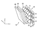
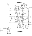
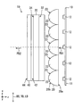
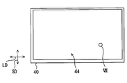
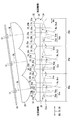
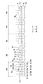
- the drawing It is a schematic diagram which shows the mounting state to the vehicle of the HUD apparatus in 1st Embodiment, It is a perspective view which shows typically the image projection unit in 1st Embodiment, It is a figure which shows the image projection unit in 1st Embodiment, Comprising: It is sectional drawing which shows a yz cross section typically, It is a figure which shows the image projection unit in 1st Embodiment, Comprising: It is sectional drawing which shows a xz cross section typically, FIG.
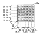
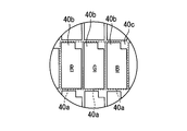
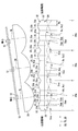
- FIG. 5 is a partial front view of the projection lens according to the first embodiment, and is a diagram for explaining a deflection element in one divided block; It is the figure which looked at the image display panel in 1st Embodiment along the normal line direction of the display surface, FIG. 7 is an enlarged view showing a portion VII of FIG.
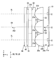
- the HUD device 100 As shown in FIG. 1, the HUD device 100 according to the first embodiment of the present disclosure is mounted on a vehicle 1 that is a kind of moving body and is housed in an instrument panel 2.
- the HUD device 100 projects image display light onto a windshield 3 as a projection member of the vehicle 1.
- HUD device 100 displays a virtual image so that a crew member of vehicles 1 can recognize visually. That is, the display light reflected by the windshield 3 reaches the occupant's eye point EP in the vehicle 1 and the occupant perceives the display light as a virtual image VI.
- the occupant can recognize various information displayed as the virtual image VI. Examples of various information displayed as the virtual image VI include vehicle state values such as vehicle speed and fuel remaining amount, or vehicle information such as road information and visibility assistance information.
- the windshield 3 of the vehicle 1 is formed in a plate shape with translucent glass or synthetic resin.
- the windshield 3 forms a projection surface 3a on which display light is projected in a smooth concave or flat shape.
- a combiner instead of the windshield 3, a combiner separate from the vehicle 1 may be installed in the vehicle 1, and an image may be projected onto the combiner.
- the HUD device 100 itself may include a combiner as a projection member.
- the HUD device 100 includes an illumination light source unit 10, a condenser lens 20, a projection lens 30, an image display panel 40, and a light guide unit 50, which are housed and held in a housing 60.
- an image projection unit 19 is constituted by the illumination light source unit 10, the condenser lens 20, the projection lens 30, and the image display panel 40.
- Each element 10, 20, 30, 40 included in the image projection unit 19 is accommodated in a casing 19a having a light shielding property.
- the illumination light source unit 10 includes a light source circuit board 11 and a plurality of light emitting elements 12 as shown in FIGS.
- the light source circuit board 11 has a planar mounting surface 11a.
- the light emitting elements 12 are, for example, light emitting diode elements that generate little heat, and are arranged on the mounting surface 11a.
- Each light emitting element 12 is electrically connected to a power source through a wiring pattern on the mounting surface 11a. More specifically, each light emitting element 12 is formed by sealing a chip-like blue light emitting diode element with a yellow phosphor in which a yellow fluorescent agent is mixed with a synthetic resin having translucency. The yellow phosphor is excited by blue light emitted according to the amount of current from the blue light emitting diode element to emit yellow light, and pseudo white illumination light is emitted by mixing blue light and yellow light.
- the light emitting elements 12 are arranged in a grid pattern on the mounting surface 11a with two directions orthogonal to each other as the arrangement direction.
- the number of arranged light emitting elements 12 is, for example, a total of 15 of 3 ⁇ 5.
- the normal direction of the planar mounting surface 11a of the light source circuit board 11 is defined as the z direction.
- the direction with the larger number of arrangements, that is, five arrangement directions is defined as the x direction
- the direction with the smaller number of arrangements, that is, the three arrangement directions is defined as the y direction.
- each light emitting element 12 emits light with a predetermined light emission intensity distribution, and is arranged so that the light emission peak direction PD1 at which the light emission intensity is maximum is aligned with the z direction (see FIGS. 3 and 4). Therefore, in the present embodiment, the optical axis OA of the illumination light source unit 10 defined based on the configuration of the illumination light source unit 10 is defined as an axis along the z direction that is the emission peak direction PD1. More specifically, the optical axis OA passes through the middle light emitting element 12 located at the center of the illumination light source unit 10, and is defined as an axis along the z direction that is the light emission peak direction PD1. In other words, the illumination light source unit 10 emits illumination light in the direction along the optical axis OA by each light emitting element 12. Illumination light emitted from the illumination light source unit 10 enters the condenser lens 20.
- the condenser lens 20 is disposed between the illumination light source unit 10 and the projection lens 30.
- the condenser lens 20 condenses the illumination light from the illumination light source unit 10 side and emits it toward the projection lens 30.
- the condensing lens 20 is a lens array in which a plurality of convex lens elements 22 made of translucent synthetic resin or glass are arranged in an integrated manner.
- Each convex lens element 22 is a lens element provided in the same number as the light emitting elements 12 so as to be paired with each light emitting element 12 individually. That is, each convex lens element 22 has a total of 15 arrays of 3 ⁇ 5.
- the incident-side surface 20 a facing the illumination light source unit 10 is a single flat surface having a smooth flat shape common to the convex lens elements 22.
- condensing surfaces 23 provided individually for each convex lens element 22 are arranged on the exit-side surface 20 b facing the projection lens 30 in the condensing lens 20, condensing surfaces 23 provided individually for each convex lens element 22 are arranged.
- the condensing surfaces 23 have substantially the same shape between the convex lens elements 22, and each condensing surface 23 is formed into a smooth convex surface by curving into a convex shape protruding toward the projection lens 30. .
- the arrangement interval of the light emitting elements 12 arranged mutually is substantially equal to the arrangement interval of the surface vertices of the light collection surfaces 23 arranged mutually. Further, the distance between each light emitting element 12 and the surface vertex 23a of the condensing surface 23 of the convex lens element 22 forming a pair is substantially equal in each pair.
- the arrangement direction of the light emitting elements 12 and the arrangement direction of the convex lens elements 22 substantially coincide with each other, so that the condensing lens 20 is arranged so that its radial direction is substantially perpendicular to the optical axis OA (that is, the z direction). .
- each condensing surface 23 is a rotationally symmetric aspherical surface with respect to the surface vertex 23a.
- each condensing surface 23 is formed in a parabolic shape in the xz section (see FIG. 4), and is also formed in a parabolic shape in the yz section (see FIG. 3).
- the projection lens 30 is disposed between the illumination light source unit 10 and the image display panel 40, more strictly between the condenser lens 20 and the image display panel 40.
- the projection lens 30 projects illumination light incident from the illumination light source unit 10 side onto the image display panel 40.
- the projection lens 30 is a lens array in which a plurality of deflecting elements 30b made of translucent synthetic resin or glass are arranged in an integrated manner, and has a substantially flat plate shape as a whole. ing.
- the deflection elements 30b are arranged with each other along the radial direction DD of the projection lens 30.
- Each deflection element 30b can deflect the traveling direction of the illumination light by refraction at split lens surfaces 33 and 35, which will be described later.
- the projection lens 30 constitutes a plurality of deflection elements 30b arranged in each of the divided blocks 30a.
- a total of 36 6 ⁇ 6 deflection elements 30b corresponding to the number of division lens surfaces 33 and 35 to be described later are arranged in one division block 30a.
- the radial direction DD coincides with the extending direction perpendicular to the plate thickness direction.
- Such a projection lens 30 is tilted so that the thickness direction intersects the optical axis OA (that is, the z direction).
- the image display panel 40 is a liquid crystal panel using thin film transistors (TFTs), and is an active matrix type liquid crystal panel formed from a plurality of liquid crystal pixels 40a arranged in two directions, for example.
- TFTs thin film transistors
- the image display panel 40 has a rectangular shape having a longitudinal direction LD and a short direction SD.
- the liquid crystal pixels 40a are arranged in the longitudinal direction LD and the short direction SD, so that the display surface 44 that displays an image on the light guide unit 50 side also has a rectangular shape.
- a transmissive portion 40b provided so as to penetrate in the normal direction ND of the display surface 44 and a wiring portion 40c formed so as to surround the transmissive portion 40b are provided.
- the image display panel 40 has a flat plate shape by being formed by laminating a pair of polarizing plates and a liquid crystal layer sandwiched between the pair of polarizing plates.
- Each polarizing plate has a property of transmitting light polarized in a predetermined direction and absorbing light polarized in a direction perpendicular to the predetermined direction.
- the pair of polarizing plates has the predetermined direction orthogonal to each other. Has been placed.
- the liquid crystal layer can rotate the polarization direction of light incident on the liquid crystal layer according to the applied voltage by applying a voltage to each liquid crystal pixel 40a. By rotating the polarization direction, the ratio of light transmitted through the subsequent polarizing plate, that is, the transmittance can be changed.
- the image display panel 40 controls the transmittance of the illumination light for each liquid crystal pixel 40a with respect to the illumination light incident on the illumination target surface 42 which is the surface on the illumination light source unit 10 side. That is, the image display panel 40 displays an image by transmitting a part of the illumination light from the illumination light source unit 10 side and emitting it as display light from the display surface 44 that is the light guide unit 50 side surface.
- Adjacent liquid crystal pixels 40a are provided with color filters of different colors (for example, red, green, and blue), and various colors are realized by combining these color filters.
- the display surface 44 is formed so as to be able to reflect light incident on the image display panel 40 from the light guide unit 50 side, for example, using a mirror-like surface of a glass substrate in the image display panel 40.
- the illumination light is incident on the illumination target surface 42 of the image display panel 40 along the optical axis OA.
- the image display panel 40 is inclined so that the normal direction ND of the illumination target surface 42 and the display surface 44 intersects the optical axis OA.
- the image display panel 40 is inclined so that the longitudinal direction LD of the tangential direction TD of the display surface 44 is orthogonal to the optical axis OA, and the lateral direction SD is inclined with respect to the optical axis OA. Yes.
- the longitudinal direction LD is along the x direction.
- the image display panel 40 takes a posture rotated from the posture in which the normal direction of the display surface 44 is orthogonal to the optical axis OA, with the longitudinal direction LD (that is, the x direction) as the rotation axis.
- the crossing angle ⁇ in the normal direction ND of the display surface 44 with respect to the optical axis OA is, for example, about 10 to 25 degrees.
- the emission peak direction PD2 in which the emission intensity is the largest among the display light is not changed by the image display panel 40. It is generally along the axis OA. That is, the emission peak direction PD2 of the display light is different from the normal direction ND of the display surface 44. In this way, the image projection unit 19 projects display light onto the light guide unit 50.
- the light guide unit 50 guides display light from the image display panel 40 of the image projection unit 19 to the windshield 3.
- the light guide unit 50 of this embodiment includes a plane mirror 51 and a concave mirror 53. In the present embodiment, display light from the image display panel 40 first enters the plane mirror 51.
- the plane mirror 51 is formed by evaporating aluminum as the reflective surface 52 on the surface of a base material made of synthetic resin or glass.
- the reflecting surface 52 is formed in a smooth flat shape.
- the display light incident on the plane mirror 51 is reflected by the reflecting surface 52 toward the concave mirror 53.
- the concave mirror 53 is formed by evaporating aluminum as the reflective surface 54 on the surface of a base material made of synthetic resin or glass.
- the reflecting surface 54 is formed in a smooth concave shape by curving into a concave shape in which the center of the concave mirror 53 is concave.
- the display light incident on the concave mirror 53 is reflected toward the windshield 3 by the reflecting surface 54.
- a window 61 is provided in the housing 60 between the concave mirror 53 and the windshield 3.
- the window 61 is covered with a translucent dustproof cover 62. Therefore, the display light from the concave mirror 53 passes through the dust cover 62 and enters the windshield 3. Thus, the occupant can visually recognize the display light reflected by the windshield 3 as a virtual image VI.
- external light such as sunlight can pass through the windshield 3 and enter the window 61.
- a part of the external light incident on the window portion 61 is reverse to the display light, that is, is reflected in turn by the concave mirror 53 and the plane mirror 51 of the light guide portion 50, and is reflected on the display surface 44 of the image display panel 40.
- the normal direction ND of the display surface 44 intersects the optical axis OA, so that external light incident on the display surface 44 can be reflected in a direction different from the display light.
- the inclination direction or angle of the image display panel 40 is set so as to satisfy or close to the Scheimpflug condition in consideration of the arrangement angle of the plane mirror 51, the concave mirror 53, and the windshield 3. It is preferred that According to such an inclination direction and angle, it is possible to suppress the virtual image VI viewed from the eye point EP from being inclined and viewed.
- the projection lens 30 is also tilted in correspondence with the image display panel 40. Specifically, the projection lens 30 is inclined so that its radial direction DD matches the tangential direction TD of the display surface 44. As a result, as described above, the thickness direction of the projection lens 30 intersects the optical axis OA (that is, the z direction).
- the image display panel 40 and the projection lens 30 of the present embodiment are arranged so as to avoid interference with each other.
- the interference here includes optical interference in addition to spatial interference in which the image display panel 40 and the projection lens 30 collide with each other. If the distance between the image display panel 40 and the projection lens 30 is partially narrowed due to the angular difference in arrangement, moire fringes can be observed only in a part of the image. In such moire fringes, there is a concern that the boundary between the deflection elements 30b in the projection lens 30 described above is emphasized.
- the distance between the image display panel 40 and the projection lens 30 is constant.
- the image display panel 40 and the projection lens 30 are arranged in parallel to each other by making the distance between the image display panel 40 and the projection lens 30 constant.
- the shape of the projection lens 30 is adapted to such an inclined arrangement.
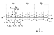
- the shape of the projection lens 30 will be described in detail with reference to FIGS.
- a plurality of divided lens surfaces 33 are aligned with the boundary between adjacent deflection elements 30b as components of the deflection element 30b. Are formed in a striped state.
- the dividing direction of the dividing lens surface 33 on the incident-side surface 32 is along the short direction SD inclined by, for example, about 10 to 25 degrees from the y direction. Therefore, in the xz cross section, one divided lens surface 33 is formed across the deflection element 30b and the divided block 30a.
- Each divided lens surface 33 is arranged so that the component in the xz cross section in the normal direction thereof is along the optical axis OA, and the component in the yz cross section in the normal direction is intersected with the optical axis OA. Therefore, the incident side surface 32 is mainly configured to deflect the traveling direction of the illumination light in the yz section.
- a plurality of divided lens surfaces 35 are the boundaries between adjacent deflection elements 30 b as constituent elements of the deflection element 30 b. And is formed in a state of being divided into stripes.
- the dividing direction of the divided lens surface 35 on the exit side surface 34 is along the longitudinal direction LD (that is, the x direction). Therefore, in the yz section, one divided lens surface 35 is formed across the deflection element 30b and the divided block 30a.
- Each divided lens surface 35 is arranged so that the component in the yz section in the normal direction thereof is along the optical axis OA and the component in the xz section in the normal direction intersects the optical axis OA. Therefore, the emission side surface 34 is mainly configured to deflect the traveling direction of the illumination light in the xz section.
- the emission side surface 34 is configured to have substantially the same shape for each of the divided blocks 30a divided into five in accordance with the number of the light emitting elements 12 corresponding to the x direction.
- each approximate plane 35a and each anisotropic deflection plane 35b are formed as one divided region divided into regions with a predetermined division width Wa.
- the predetermined division width Wa is set to be substantially constant.
- the approximate plane 35 a is formed based on a virtual convex curved surface Svb defined as a virtual lens surface in the projection lens 30.
- the virtual convex curved surface Svb exhibits a smooth cylindrical surface shape by being curved in the xz cross section into a convex shape convex toward the image display panel 40 side.
- the approximate plane 35a is formed in a planar shape as an approximate plane obtained by linear interpolation of a plurality of coordinates extracted from the virtual convex curved surface Svb.
- the end coordinates Ce of the virtual convex curved surface Svb at the ends of the divided regions are employed as the plurality of coordinates, and the gradient of the approximate plane 35a is obtained by linear interpolation between the end coordinates Ce. It is prescribed.
- the virtual convex curved surface Svb appears on the emission side surface 34 in a state of being planar by partial approximation.
- the anisotropic deflection plane 35b is arranged in a state of being interposed between the approximate planes 35a.
- the anisotropic deflection plane 35b is formed based on a virtual inclined surface Ssb defined as a virtual lens surface in the projection lens 30.
- the virtual inclined surface Ssb is composed of a plurality of planar inclined surfaces Ssp that change in reverse gradient at locations corresponding to the surface vertices of the virtual convex curved surface Svb, and the gradient of each planar inclined surface Ssp is the virtual convex surface.
- the slope of the corresponding portion of the curved surface Svb is set to be opposite to the slope.
- six divided lens surfaces 35 are provided for one divided block 30a.
- the six divided lens surfaces 35 are arranged in the order of the approximate plane 35a, the anisotropic deflection plane 35b, the approximate plane 35a, the approximate plane 35a, the anisotropic deflection plane 35b, and the approximate plane 35a, and the boundary between the adjacent approximate planes 35a. Is a portion corresponding to the surface vertex of the virtual convex curved surface Svb. Accordingly, since the gradient is switched to the reverse gradient for each divided lens surface 35, the projection lens 30 is maintained in a substantially flat plate shape even when the boundaries between the divided lens surfaces 35 are connected without a step.
- each divided lens surface 33 on the incident side surface 32 will be described.
- the incident-side surface 32 is configured in a different shape for each divided block 30 a that is divided into three according to the number of light emitting elements 12 corresponding to the x direction.
- a plurality of approximate planes 33a and a plurality of anisotropic deflection planes 33b are provided as the divided lens surface 33 in the same manner as the exit side surface 34.
- Each approximate plane 33a and each anisotropic deflection plane 33b are formed as one divided region divided into regions with a predetermined division width Wa.
- the predetermined division width Wa is set to be substantially constant.
- the approximate plane 33 a is formed based on a virtual convex curved surface Sva defined as a virtual lens surface in the projection lens 30.
- the virtual convex curved surface Sva exhibits a smooth cylindrical surface shape by being curved in the yz section into a convex shape that is convex toward the condenser lens 20 side.
- the approximate plane 33a is formed in a planar shape as an approximate plane obtained by linear interpolation of a plurality of coordinates extracted from the virtual convex curved surface Sva.
- the end coordinates Ce of the virtual convex curved surface Sva at the ends of the divided areas are adopted as the plurality of coordinates, and the gradient of the approximate plane 33a is obtained by linear interpolation between the end coordinates Ce. It is prescribed.
- the virtual convex curved surface Sva appears on the incident side surface 32 in a state of being flat by partial approximation.
- the end coordinates Ce are shown in a part of FIG. 9 and are omitted in FIG. 8 because they are the same.
- the anisotropic deflection plane 33b is arranged in a state of being interposed between the approximate planes 33a.
- the anisotropic deflection plane 33 b is formed based on a virtual inclined surface Ssa defined as a virtual lens surface in the projection lens 30.
- the virtual inclined surface Ssa is composed of a plurality of planar inclined surfaces Ssp that change in reverse gradient at locations corresponding to the surface vertices of the virtual convex curved surface Sva in the yz section.
- the gradient of each planar inclined surface Ssp is the virtual convex surface
- the slope of the corresponding portion of the curved surface Sva is set so as to be opposite to the slope.
- a part of the virtual inclined surface Ssa is extracted and appears on the exit-side surface 34.
- six divided lens surfaces 33 are provided for one divided block 30a.
- the six divided lens surfaces 33 are arranged in the order of the approximate plane 33a, the anisotropic deflection plane 33b, the approximate plane 33a, the approximate plane 33a, the anisotropic deflection plane 33b, and the approximate plane 33a, and the boundary between the adjacent approximate planes 33a. Is a portion corresponding to the surface vertex of the virtual convex curved surface Sva. Therefore, since the gradient is switched to the reverse gradient for each divided lens surface 33, the projection lens 30 is maintained in a substantially flat plate shape even when the boundaries between the divided lens surfaces 33 are connected without a step.
- the incident-side surface 20a has a different gradient of the approximate plane 33a for each divided block 30a.
- the curvature radius Rv of the base virtual convex curved surface Sva is different. Therefore, the gradient of the approximate plane 33a is different for each divided block 30a.
- the distance from the short-distance side where the distance to the illumination light source unit 10 is short is directed to the long-distance side where the distance from the illumination light source unit 10 is long.
- the radius of curvature Rv of the virtual convex curved surface Sva of each divided block 30a changes so as to be small.
- the curvature radii are Rv1, Rv2, and Rv3 in order from the divided block 30a on the short distance side, Rv1 ⁇ Rv2 ⁇ Rv3. Therefore, the gradient of the approximate plane 33a in the divided block 30a on the long distance side is relatively larger than that on the short distance side.
- the gradient of the anisotropic deflection plane 33b is set to be substantially equal in each divided block 30a.
- a location on the approximate plane 33a corresponding to the surface vertex of the virtual convex curved surface Sva extends from the surface vertex 23a of the corresponding condensing surface 23 of the condensing lens 20 along the optical axis OA.
- the illumination light source unit 10, the condensing lens 20, and the projection lens 30 in the present embodiment can be understood as an arrangement of such illumination units IU.
- the illumination light incident on the approximate plane 33a is deflected in the traveling direction so as to approach the corresponding straight line SL.
- the deflection amount by which the illumination light is deflected depends on the gradient of each approximate plane 33a with respect to the radial direction DD.
- the condensing lens is obtained from the radius of curvature of the condensing surface 23 of the condensing lens 20 and the radii of curvature Rv of the virtual convex curved surfaces Sva and Svb that form the basis of the approximate planes 33a and 35a of the projection lens 30. 20 and the projection focus of the projection lens 30 can be defined.
- the position of the synthetic focus and the position of the illumination light source unit 10 can be close to each other, the illumination lights refracted by the different approximate planes 33a are close to each other in the traveling direction component in the yz section. Deflected.
- the illumination lights refracted by the different approximate planes 35a are deflected so that the components in the traveling direction in the xz cross section approach each other. Accordingly, the illumination lights refracted by the different deflecting elements 30b are converted into a parallel light flux before the projection lens 30 is incident.
- a convex lens element is obtained from the radius of curvature of the condensing surface 23 in each illumination unit IU and the radius of curvature Rv of the virtual convex curved surfaces Sva and Svb that are the basis of the approximate planes 33a and 35a in the divided block 30a.
- the composite focus of 22 and the divided block 30a can be defined.
- the position of this synthetic focus can be defined for each illumination unit IU.
- the distance between the divided block 30a and the light emitting element 12 is different in each illumination unit IU on the yz section.
- the curvature radius Rv of the virtual convex curved surface Sva on which the approximate plane 33a is based is made different for each divided block 30a, so that the position of the light-emitting element 12 corresponding to the position of the synthetic focal point. This makes it possible to set the position closer.
- the anisotropic deflection plane 35b disposed adjacent to the approximate planes 33a and 35a deflects illumination light in a different direction from the approximate planes 33a and 35a that are separated from each other by refraction.
- a part of the illumination light is mixed with the illumination light that is refracted on the approximate planes 33a and 35a by refraction on the anisotropic deflection planes 33b and 35b. Therefore, it is possible to suppress the display light emitted from the display surface 44 of the image display panel 40 from being concentrated and emitted in the emission peak direction PD2.
- each deflection element 30b is exhibited by the combination of the striped lens surfaces 33 and 35 extending substantially orthogonal to each other on both surfaces 32 and 34 of the projection lens 30.
- the base in the deflection of the illumination light of each deflecting element 30b is determined by the gradient in the yz section of the split lens surface 33 on the incident side surface 32 and the gradient in the xz section of the split lens surface 35 on the exit side surface 34.
- the direction and amount of deflection can be determined.
- the deflection amount can be expressed by, for example, an angle difference between an incident angle and an emission angle of illumination light to one deflection element 30b.
- the average value of the deflection amount of each deflection element 30b constituting each divided block 30a changes stepwise from the short distance side toward the long distance side.
- the average value of the deflection amount of each deflection element 30b constituting the divided block 30a is larger on the far side.
- the average value of the deflection amounts of the deflection elements 30b disposed on the short distance side and the average value of the deflection amounts of the deflection elements 30b disposed on the long distance side are mutually different. Is different.
- the average value of the deflection amounts of the deflection elements 30b arranged on the long distance side is larger than the average value of the deflection amounts of the deflection elements 30b arranged on the short distance side.
- the normal direction ND of the display surface 44 is shifted with respect to the optical axis OA.
- the projection lens 30 is tilted so that the radial direction DD is aligned with the tilted image display panel 40.
- the projection lens 30 and the image display are suppressed while suppressing interference between the projection lens 30 and the image display panel 40.
- Generation of a dead space between the panel 40 can be suppressed. Therefore, an increase in the physique of the HUD device 100 can be suppressed, and the HUD device 100 that is highly mountable on the vehicle 1 as a moving body can be provided.
- the image display panel 40 and the projection lens 30 are arranged in parallel to each other. In this way, the distance between the projection lens 30 and the image display panel 40 can be minimized while suppressing interference between the projection lens 30 and the image display panel 40.
- the condensing lens 20 disposed between the illumination light source unit 10 and the projection lens 30 has a condensing surface 23 that is curved in a convex shape protruding toward the projection lens 30 side. . Therefore, when the projection lens 30 is tilted according to the image display panel 40, the end of the projection lens 30 that is close to the condenser lens 20 side is on the side of the condenser surface 23 along the curve of the condenser surface 23. It will be placed around the space. For this reason, the distance from the illumination light source unit 10 to the tip of the image display panel 40 is increased while obtaining the condensing effect of the condensing lens 20 and avoiding interference between the projection lens 30 and the condensing lens 20. Can be suppressed. Therefore, an increase in the physique of the HUD device 100 can be suppressed, and the HUD device 100 with high mountability on the vehicle 1 can be provided.
- the projection lens 30 includes a plurality of deflecting elements 30b arranged in the radial direction DD and deflecting the traveling direction of the illumination light.
- the values are different from each other.
- the average value of the deflection amount of the deflection element 30b constituting each divided block 30a changes stepwise from the short distance side toward the long distance side. If it does in this way, each illumination light corresponding to each light emitting element 12 will receive the deflection
- the projection lens 30 has a plurality of approximate planes 33a or 35a that are formed in a planar shape by partial approximation of the virtual convex curved surface Sva or Svb as a component of the deflection element 30b. . Since each approximate plane 33a or 35a is planar but based on a common virtual convex curved surface Sva or Svb, each illumination light incident on a different approximate plane 33a or 35a is applied to the virtual convex curved surface Sva or Svb. Since the traveling direction is deflected by a corresponding amount of deflection, an action substantially similar to the light collecting action can occur between the illumination lights. Therefore, it is possible to easily form the projection lens 30 and to suppress the increase in the size of the HUD device 100 and suitable illumination for the tilted image display panel 40.
- the image projection unit 19 having the image display panel 40 in which the normal direction ND of the display surface 44 intersects the optical axis OA projects display light onto the light guide unit 50.
- the image projection unit 19 even if external light such as sunlight enters the image display panel 40 in a direction opposite to the display light through the light guide 50, the external light is incident on the display surface 44. It is particularly suitable for use in the HUD device 100 because it is suppressed from being reflected and visually recognized together with the display light.
- the projection lens 30 is tilted so that the radial direction DD is aligned with the tilted image display panel 40. According to the inclination of both the projection lens 30 and the image display panel 40, since there is no or little difference in arrangement angle, the projection lens 30 and the image display are suppressed while suppressing interference between the projection lens 30 and the image display panel 40. Generation of a dead space between the panel 40 can be suppressed. Therefore, since the increase in the physique of the image projection unit 19 can be suppressed, the mountability of the HUD device 100 on the vehicle 1 can be improved.
- the second embodiment of the present disclosure is a modification of the first embodiment.
- the second embodiment will be described with a focus on differences from the first embodiment.
- the plurality of light emitting elements 12 are arranged in a grid pattern with one direction on the mounting surface 11 a as the arrangement direction.
- the number of arranged light emitting elements 12 is, for example, all three of 1 ⁇ 3.
- the normal direction of the planar mounting surface 11a of the light source circuit board 11 is defined as the z direction.
- the direction with the larger number of arrangements, that is, the three arrangement directions are defined as the x direction
- the direction with the smaller number of arrangements, that is, one arrangement direction (in this embodiment, substantially Direction) is defined as the y direction.
- Each light emitting element 12 is arranged with the light emission peak direction PD1 aligned with the z direction, as in the first embodiment.
- the optical axis OA of the illumination light source unit 210 passes through the middle light emitting element 12 located at the center of the illumination light source unit 210 and is defined as an axis along the z direction that is the emission peak direction PD1.
- each convex lens element 22 is arranged in a total of three 1 ⁇ 3.
- the incident-side surface 20a is a single flat surface similar to that of the first embodiment.
- the condensing surface 223 provided for each convex lens element 22 is arranged on the exit side surface 20b.
- each condensing surface 223 has the same arrangement and arrangement as in the first embodiment, but its detailed shape is different from that in the first embodiment. Specifically, each condensing surface 223 is an anamorphic surface in which the curvature radius in the x direction and the curvature radius in the y direction are different from each other. In the present embodiment, the curvature radius in the x direction is smaller than the curvature radius in the y direction at the surface vertex 23a of each condensing surface 223 and in the vicinity thereof.
- the vicinity of the surface vertex 23a in this embodiment refers to a range in which the distance from the surface vertex 23a is about half the value of the diameter of the condensing surface 223, for example.
- each condensing surface 223 is formed in a parabolic shape (see FIG. 11).
- each condensing surface 223 is formed in an arc shape (particularly in a semicircular shape in the present embodiment) (see FIG. 10).
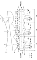
- the projection lens 230 is a lens array in which a plurality of deflecting elements 30b made of translucent synthetic resin or glass are arranged and integrated with each other. It has a substantially flat plate shape.
- the same divided block 30a as in the first embodiment can be defined.
- a total of three 1 ⁇ 3 divided blocks 30a divided into three corresponding to the number of arranged light emitting elements 12 can be defined.
- the longitudinal direction LD along the x direction of the tangential direction TD of the display surface 44 is orthogonal to the optical axis OA and the short direction SD is relative to the optical axis OA, as in the first embodiment.
- the projection lens 230 is also inclined.
- the image display panel 40 and the projection lens 230 are arranged in parallel to each other.
- the condensing lens 220 and the projection lens 230 are partially overlapped in the vertical direction perpendicular to the optical axis OA (in this embodiment, the y direction on the yz section). . This is because one end portion of the projection lens 230 is disposed in the lateral space of the condensing surface 223 due to the inclined arrangement of the projection lens 230.
- the shape of the projection lens 230 is not particularly adapted to such an inclined arrangement.
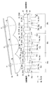
- the shape of the projection lens 230 will be described in detail.
- a plurality of divided lens surfaces 33 are divided into stripes in accordance with the boundaries between adjacent deflection elements 30b as constituent elements of the deflection element 30b. It is formed in a state.
- the dividing direction of the dividing lens surface 33 on the incident-side surface 32 is along the short direction SD inclined by, for example, about 10 to 25 degrees from the y direction. Therefore, in the xz cross section, one divided lens surface 33 is formed across the deflection element 30b and the divided block 30a.
- each divided lens surface 33 is a divided convex surface 233c divided into a convex Fresnel lens shape.
- the divided convex surface 233c is formed based on one virtual convex curved surface Svc defined as a virtual lens surface in the projection lens 230.
- the virtual convex curved surface Svc has a smooth cylindrical surface shape by being curved in the yz section into a convex shape convex toward the condenser lens 220 side. Therefore, the incident side surface 32 is mainly configured to deflect the traveling direction of the illumination light in the yz section.
- the emission side surface 34 has a reduced number of divided blocks 30 a corresponding to the number of light emitting elements 12 arranged, but the configuration in each divided block 30 a is This is the same as in the first embodiment.
- a position on the divided convex surface 233c and a position on the approximate plane 35a corresponding to the surface vertices of the virtual convex curved surfaces Svc and Svb are the surface vertices 23a of the corresponding condensing surface 223 in the condensing lens 220.
- the projection lens 230 is inclined so that the radial direction DD matches the tangential direction TD of the display surface 44, it is possible to achieve the operational effects according to the first embodiment. It becomes.
- the condensing lens 220 and the projection lens 230 are partially overlapped in the vertical direction perpendicular to the optical axis OA. The dead space between the two can be reduced.
- the third embodiment of the present disclosure is a modification of the first embodiment.
- the third embodiment will be described with a focus on differences from the first embodiment.
- the projection lens 330 according to the third embodiment is also adapted to the inclined arrangement.
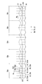
- the shape of the projection lens 330 will be described in detail.
- a plurality of divided lens surfaces 33 are divided into stripes in accordance with the boundaries of adjacent deflection elements 30b as constituent elements of the deflection elements 30b. It is formed with.
- the dividing direction of the dividing lens surface 33 on the incident side surface 32 is along the short direction SD inclined by, for example, about 10 to 25 degrees from the y direction.
- Each divided lens surface 33 is arranged such that the component in the yz section in the normal direction thereof is along the optical axis OA.
- the incident side surface 32 is mainly configured to deflect the traveling direction of the illumination light in the yz section.
- a plurality of divided lens surfaces 35 are divided into stripes in accordance with the boundaries of the deflection element 30b as components of the deflection element 30b. It is formed with.
- the splitting direction of the split lens surface 35 on the exit side surface 34 is along the longitudinal direction LD (that is, the x direction) as in the first embodiment.
- Each of the divided lens surfaces 35 is disposed so that the component in the xz cross section in the normal direction is along the optical axis OA.
- the exit side surface 34 is mainly configured to deflect the traveling direction of the illumination light in the xz section.
- the approximate planes 33a and 35a of the first embodiment of the divided lens surfaces 33 and 35 are replaced with convex curved surfaces 333d and 335d that are curved in a convex shape.
- the convex curved surfaces 333d and 335d are formed based on virtual convex curved surfaces Sva and Svb defined as virtual lens surfaces in the projection lens 330.
- the virtual convex curved surfaces Sva and Svb are the same as those in the first embodiment.
- the convex curved surfaces 333d and 335d do not approximate the virtual convex curved surfaces Sva and Svb, and are extracted from the virtual convex curved surfaces Sva and Svb as they are, so that they appear on the incident side surface 32 and the emission side surface 34. I'm out.
- the two approximate planes 33a or 35a in the first embodiment are replaced with one convex curved surface 333d or 335d, so that the division width Wa is another division. It is twice the area.
- the curvature radius Rv of the virtual convex curved surface Svb on the exit side surface 34 is set to be substantially equal between the divided blocks 30a. Therefore, the emission side surface 34 is configured to have substantially the same shape for each of the divided blocks 30a divided into five in accordance with the number of the light emitting elements 12 corresponding to the x direction.
- the incident-side surface 32 is configured in a different shape for each of the divided blocks 30a divided into three according to the number of arrangement of the light emitting elements 12 corresponding to the x direction.
- the radius of curvature Rv of the virtual convex curved surface Sva differs among the divided blocks 30a.
- the distance from the short-distance side where the distance to the illumination light source unit 10 is short is directed to the long-distance side where the distance from the illumination light source unit 10 is long. Accordingly, the radius of curvature Rv of the virtual convex curved surface Sva of each divided block 30a changes so as to decrease stepwise.
- each convex curved surface 333d changes in a stepwise manner from the short distance side toward the long distance side. Accordingly, the gradient of the convex curved surface 333d is different for each divided block 30a, and the gradient of the convex curved surface 333d in the divided block 30a on the far distance side is relatively larger than that on the short distance side.
- the gradient of the anisotropic deflection plane 33b is set to be substantially equal in each divided block 30a, as in the first embodiment.
- the projection lens 330 is inclined so that the radial direction DD is aligned with the tangential direction TD of the display surface 44, it is possible to achieve the operational effects according to the first embodiment. It becomes.
- the projection lens 30 has convex curved surfaces 333d and 335d that are curved in a convex shape as components of the deflection element 30b. Since the illumination light incident on the convex curved surfaces 333d and 335d is subjected to a condensing function, it is possible to realize the suppression of the physique increase of the HUD device 100 and the suitable illumination to the tilted image display panel 40. Can do.
- the curvature radii Rv1 to Rv3 of the convex curved surfaces 333d change in a stepwise manner from the short distance side to the long distance side of the projection lens 330. If it does in this way, each illumination light which passed each convex-shaped curved surface 333d will receive the condensing effect
- the light emitting element 12 may be decentered toward the center of the illumination light source unit 10 with respect to the arrangement pitch of the convex lens elements 22 as shown in FIG. In this case, the amount of eccentricity of each light emitting element 12 may be set asymmetrically across the central light emitting element 12.
- the light emitting element 12 is not arranged on a straight line but is arranged so as to match the position of the synthetic focus of the convex lens element 22 and the divided block 30a. Also good.
- the light source circuit board 11 is a flexible board with a mounting surface 11 a having a curved curved surface, and a plurality of light emitting elements 12 are arranged in a curved shape. Therefore, the light emitting elements 12 may be arranged asymmetrically with the center in between.
- the condenser lens 20 may not be provided.
- the radius of curvature Rv of the virtual convex curved surface Sva of each divided block 30a gradually increases from the short distance side to the long distance side. You may change so that it may become large.
- the curvature radii are Rv1, Rv2, Rv3 in order from the divided block 30a on the short distance side, Rv1> Rv2> Rv3.
- the magnitude relationship between the radius of curvature Rv on the near side and the far side may vary depending on various design conditions such as the presence / absence of the condenser lens 20 and the focal length and arrangement of the condenser lens 20.
- the division width may be set so that the sag amount of each of the divided lens surfaces 33 and 35 is substantially constant.
- deviation element 30b can be set arbitrarily.
- the projection lens 30 instead of making the average value of the deflection amount of the deflection element 30b disposed on the short distance side different from the average value of the deflection amount of the deflection element 30b disposed on the long distance side.
- the direction from the surface vertex of the virtual convex curved surface Sva toward the center of curvature may be different between the short distance side and the long distance side.
- the approximate plane 33a is formed in a flat shape by partial approximation of the virtual convex curved surface Sva, for example, the contact of the virtual convex curved surface Sva at the midpoint of the divided region is used. It may be formed by extracting a plane.
- the condensing surface 23 may be formed in a spherical shape.
- the projection lens 30 may have a shape in which the shapes of the incident side surface 32 and the emission side surface 34 are interchanged.
- the projection lens 30 may have a slight angle difference with the image display panel 40 as long as the projection lens 30 is inclined so as to match the radial direction DD with the tangential direction TD of the display surface 44.
- the projection lens 30 may not have a plurality of deflection elements 30b arranged along the radial direction DD. Specifically, even in the case of a convex lens having a single lens surface on each of the incident side surface 32 and the emission side surface 34, the present disclosure can be applied if the radius of curvature of the lens surface is set to be large. it can.
- the present disclosure may be applied to various moving bodies (transportation equipment) such as ships or airplanes other than the vehicle 1.
- the above-described head-up display device is mounted on the moving body 1 and projects an image display light onto the projection member 3 to display a virtual image so that the occupant can visually recognize the image.
- the head-up display device includes illumination light source units 10 and 210, an image display panel 40, and projection lenses 30, 230, and 330.
- the illumination light source units 10 and 210 emit illumination light.
- the image display panel 40 displays an image by allowing illumination light from the illumination light source unit side to pass through and exiting from the display surface 44 as display light.
- the projection lenses 30, 230, and 330 are disposed between the illumination light source unit and the image display panel, and project illumination light from the illumination light source unit side onto the image display panel.
- the image display panel is inclined so that the normal direction ND of the display surface intersects the optical axis OA of the illumination light source unit.
- the projection lens is tilted so that the radial direction DD of the projection lens matches the tangential direction TD of the display surface.
- the normal direction of the display surface is shifted with respect to the optical axis.
- the projection lens is inclined so that the radial direction is aligned with the inclined image display panel. According to the inclination of both the projection lens and the image display panel, since there is no or small angular difference in arrangement, the interference between the projection lens and the image display panel is suppressed, and the projection lens and the image display panel are Generation of dead space can be suppressed. Therefore, an increase in the physique of the HUD device can be suppressed, and a HUD device that is highly mountable on a moving body can be provided.
- the above-described head-up display device 100 is mounted on the moving body 1 and projects an image display light onto the projection member 3 to display a virtual image so that the occupant can visually recognize the image.
- the image projection unit 19 projects the display light onto the light guide 50 that guides the display light to the projection member.
- the image projection unit 19 includes illumination light source units 10 and 210, an image display panel 40, and projection lenses 30, 230, and 330.
- the illumination light source units 10 and 210 emit illumination light.
- the image display panel 40 displays an image by allowing illumination light from the illumination light source unit side to pass through and exiting from the display surface 44 as display light.
- the projection lenses 30, 230, and 330 are disposed between the illumination light source unit and the image display panel, and project illumination light from the illumination light source unit side onto the image display panel.
- the image display panel is inclined so that the normal direction ND of the display surface intersects the optical axis OA of the illumination light source unit.
- the projection lens is inclined so that the radial direction DD of the projection lens matches the tangential direction TD of the display surface.
- an image projection unit having an image display panel in which the normal direction of the display surface intersects the optical axis projects display light onto the light guide unit.
- an image projection unit even if external light such as sunlight enters the image display panel in a direction opposite to the display light through the light guide unit, the external light is reflected on the display surface. Since it is suppressed that it is visually recognized together with display light, it is particularly suitable for use in a HUD device.
- the projection lens is tilted so as to align the radial direction with the tilted image display panel.
- the inclination of both the projection lens and the image display panel since there is no or small angular difference in arrangement, the interference between the projection lens and the image display panel is suppressed, and the projection lens and the image display panel are Generation of dead space can be suppressed. Therefore, since the increase in the size of the image projection unit can be suppressed, the mountability of the HUD device on the moving body can be improved.
Landscapes
- Physics & Mathematics (AREA)
- General Physics & Mathematics (AREA)
- Optics & Photonics (AREA)
- Engineering & Computer Science (AREA)
- Chemical & Material Sciences (AREA)
- Nonlinear Science (AREA)
- Combustion & Propulsion (AREA)
- Transportation (AREA)
- Mechanical Engineering (AREA)
- Crystallography & Structural Chemistry (AREA)
- Instrument Panels (AREA)
- Liquid Crystal (AREA)
Priority Applications (3)
| Application Number | Priority Date | Filing Date | Title |
|---|---|---|---|
| DE112017002525.7T DE112017002525T5 (de) | 2016-05-18 | 2017-04-07 | Blickfeldanzeigevorrichtung und bildprojektionseinheit |
| US16/099,761 US10585282B2 (en) | 2016-05-18 | 2017-04-07 | Head-up display device and image projection unit |
| CN201780029833.2A CN109154721B (zh) | 2016-05-18 | 2017-04-07 | 平视显示器装置以及图像投影单元 |
Applications Claiming Priority (2)
| Application Number | Priority Date | Filing Date | Title |
|---|---|---|---|
| JP2016-099852 | 2016-05-18 | ||
| JP2016099852A JP6508125B2 (ja) | 2016-05-18 | 2016-05-18 | ヘッドアップディスプレイ装置及び画像投射ユニット |
Publications (1)
| Publication Number | Publication Date |
|---|---|
| WO2017199627A1 true WO2017199627A1 (ja) | 2017-11-23 |
Family
ID=60324973
Family Applications (1)
| Application Number | Title | Priority Date | Filing Date |
|---|---|---|---|
| PCT/JP2017/014477 Ceased WO2017199627A1 (ja) | 2016-05-18 | 2017-04-07 | ヘッドアップディスプレイ装置及び画像投射ユニット |
Country Status (5)
| Country | Link |
|---|---|
| US (1) | US10585282B2 (enExample) |
| JP (1) | JP6508125B2 (enExample) |
| CN (1) | CN109154721B (enExample) |
| DE (1) | DE112017002525T5 (enExample) |
| WO (1) | WO2017199627A1 (enExample) |
Cited By (3)
| Publication number | Priority date | Publication date | Assignee | Title |
|---|---|---|---|---|
| JP2019101056A (ja) * | 2017-11-28 | 2019-06-24 | 株式会社ジャパンディスプレイ | 表示装置およびヘッドアップ表示装置 |
| JP2020038280A (ja) * | 2018-09-04 | 2020-03-12 | 株式会社ジャパンディスプレイ | 表示装置 |
| US11347102B2 (en) * | 2018-09-04 | 2022-05-31 | Japan Display Inc. | Display device |
Families Citing this family (12)
| Publication number | Priority date | Publication date | Assignee | Title |
|---|---|---|---|---|
| JP7202191B2 (ja) * | 2019-01-17 | 2023-01-11 | マクセル株式会社 | 車両用情報表示システム |
| JP6926136B2 (ja) * | 2019-03-22 | 2021-08-25 | 矢崎総業株式会社 | ヘッドアップディスプレイ装置 |
| JP7172840B2 (ja) | 2019-05-07 | 2022-11-16 | 株式会社デンソー | 虚像表示装置 |
| JP7184018B2 (ja) * | 2019-11-11 | 2022-12-06 | 株式会社デンソー | 虚像表示装置及び偏光調整部材 |
| WO2021193646A1 (ja) * | 2020-03-26 | 2021-09-30 | 株式会社小糸製作所 | イメージング装置および車両用灯具、車両 |
| JP7479912B2 (ja) * | 2020-04-27 | 2024-05-09 | 株式会社小糸製作所 | 画像生成装置及びヘッドアップディスプレイ |
| JP7479999B2 (ja) * | 2020-09-09 | 2024-05-09 | 株式会社小糸製作所 | 画像投影装置 |
| US11169377B1 (en) * | 2020-09-16 | 2021-11-09 | E-Lead Electronic Co., Ltd. | Multi-focal plane head-up display |
| US20240184125A1 (en) * | 2021-03-31 | 2024-06-06 | Koito Manufacturing Co., Ltd. | Image generation device, image irradiation device equipped with said image generation device, and image irradiation device |
| US20230019956A1 (en) * | 2021-07-13 | 2023-01-19 | Conserve & Associates , Inc. | Picture generation unit and head-up display system using the same |
| JP7406582B2 (ja) * | 2022-02-16 | 2023-12-27 | ミネベアミツミ株式会社 | 面状照明装置 |
| CN119667960A (zh) * | 2025-01-27 | 2025-03-21 | 天马新型显示技术研究院(厦门)有限公司 | 一种显示模组及显示装置 |
Citations (5)
| Publication number | Priority date | Publication date | Assignee | Title |
|---|---|---|---|---|
| JP2010211065A (ja) * | 2009-03-11 | 2010-09-24 | Denso Corp | 表示装置 |
| JP2011247997A (ja) * | 2010-05-25 | 2011-12-08 | Nippon Seiki Co Ltd | ヘッドアップディスプレイ装置 |
| JP2015133304A (ja) * | 2014-01-15 | 2015-07-23 | 株式会社デンソー | 照明用レンズ、照明ユニット及びヘッドアップディスプレイ装置 |
| JP2015152732A (ja) * | 2014-02-13 | 2015-08-24 | 株式会社 オルタステクノロジー | ヘッドアップディスプレイ装置 |
| JP5866644B1 (ja) * | 2014-12-26 | 2016-02-17 | パナソニックIpマネジメント株式会社 | ヘッドアップディスプレイ及びヘッドアップディスプレイを備えた移動体 |
Family Cites Families (13)
| Publication number | Priority date | Publication date | Assignee | Title |
|---|---|---|---|---|
| US5867287A (en) * | 1994-09-30 | 1999-02-02 | Hughes Aircraft Company | Head up display with a lens decentered to the optical axis of the illumination |
| JP4671117B2 (ja) * | 2005-09-22 | 2011-04-13 | ミネベア株式会社 | 照明装置及びそれを用いた光源ユニット |
| JP2007108429A (ja) * | 2005-10-13 | 2007-04-26 | Denso Corp | 表示装置とそれを備えた車両用ヘッドアップディスプレイ装置 |
| JP5353203B2 (ja) * | 2007-12-18 | 2013-11-27 | 日本精機株式会社 | ヘッドアップディスプレイ装置 |
| JP5376423B2 (ja) * | 2008-04-16 | 2013-12-25 | 株式会社ジャパンディスプレイ | 投射型表示装置 |
| JP5250853B2 (ja) * | 2008-10-06 | 2013-07-31 | コニカミノルタ株式会社 | 映像表示装置およびヘッドマウントディスプレイ |
| JP2011133583A (ja) * | 2009-12-23 | 2011-07-07 | Nippon Seiki Co Ltd | 液晶表示装置 |
| JP5674032B2 (ja) * | 2011-03-25 | 2015-02-18 | 日本精機株式会社 | ヘッドアップディスプレイ装置 |
| JP5851979B2 (ja) * | 2012-12-26 | 2016-02-03 | 株式会社ジャパンディスプレイ | 表示装置 |
| JP6115420B2 (ja) * | 2013-09-17 | 2017-04-19 | 株式会社Jvcケンウッド | 画像表示装置 |
| JP2015079227A (ja) * | 2013-10-18 | 2015-04-23 | 株式会社 オルタステクノロジー | 液晶表示装置及びヘッドアップディスプレイ |
| WO2015107838A1 (ja) * | 2014-01-16 | 2015-07-23 | 株式会社Screenホールディングス | 基板処理装置 |
| JP6358057B2 (ja) | 2014-11-25 | 2018-07-18 | 株式会社デンソーウェーブ | 光学的情報読取装置 |
-
2016
- 2016-05-18 JP JP2016099852A patent/JP6508125B2/ja not_active Expired - Fee Related
-
2017
- 2017-04-07 US US16/099,761 patent/US10585282B2/en active Active
- 2017-04-07 WO PCT/JP2017/014477 patent/WO2017199627A1/ja not_active Ceased
- 2017-04-07 CN CN201780029833.2A patent/CN109154721B/zh not_active Expired - Fee Related
- 2017-04-07 DE DE112017002525.7T patent/DE112017002525T5/de not_active Withdrawn
Patent Citations (5)
| Publication number | Priority date | Publication date | Assignee | Title |
|---|---|---|---|---|
| JP2010211065A (ja) * | 2009-03-11 | 2010-09-24 | Denso Corp | 表示装置 |
| JP2011247997A (ja) * | 2010-05-25 | 2011-12-08 | Nippon Seiki Co Ltd | ヘッドアップディスプレイ装置 |
| JP2015133304A (ja) * | 2014-01-15 | 2015-07-23 | 株式会社デンソー | 照明用レンズ、照明ユニット及びヘッドアップディスプレイ装置 |
| JP2015152732A (ja) * | 2014-02-13 | 2015-08-24 | 株式会社 オルタステクノロジー | ヘッドアップディスプレイ装置 |
| JP5866644B1 (ja) * | 2014-12-26 | 2016-02-17 | パナソニックIpマネジメント株式会社 | ヘッドアップディスプレイ及びヘッドアップディスプレイを備えた移動体 |
Cited By (4)
| Publication number | Priority date | Publication date | Assignee | Title |
|---|---|---|---|---|
| JP2019101056A (ja) * | 2017-11-28 | 2019-06-24 | 株式会社ジャパンディスプレイ | 表示装置およびヘッドアップ表示装置 |
| JP2020038280A (ja) * | 2018-09-04 | 2020-03-12 | 株式会社ジャパンディスプレイ | 表示装置 |
| US11347102B2 (en) * | 2018-09-04 | 2022-05-31 | Japan Display Inc. | Display device |
| JP7110037B2 (ja) | 2018-09-04 | 2022-08-01 | 株式会社ジャパンディスプレイ | 表示装置 |
Also Published As
| Publication number | Publication date |
|---|---|
| DE112017002525T5 (de) | 2019-01-31 |
| JP2017207622A (ja) | 2017-11-24 |
| CN109154721A (zh) | 2019-01-04 |
| US10585282B2 (en) | 2020-03-10 |
| CN109154721B (zh) | 2021-03-23 |
| US20190179143A1 (en) | 2019-06-13 |
| JP6508125B2 (ja) | 2019-05-08 |
Similar Documents
| Publication | Publication Date | Title |
|---|---|---|
| WO2017199627A1 (ja) | ヘッドアップディスプレイ装置及び画像投射ユニット | |
| JP6579212B2 (ja) | ヘッドアップディスプレイ装置 | |
| JP7202191B2 (ja) | 車両用情報表示システム | |
| JP6601438B2 (ja) | ヘッドアップディスプレイ装置 | |
| US10920958B2 (en) | Head-up display device | |
| JP6601431B2 (ja) | ヘッドアップディスプレイ装置 | |
| JP7195454B2 (ja) | 光源装置、それを利用した情報表示システムおよびヘッドアップディスプレイ装置 | |
| JP7282174B2 (ja) | 情報表示システム | |
| JP7587417B2 (ja) | 空間浮遊映像表示装置および光源装置 | |
| US12124031B2 (en) | Virtual image display device | |
| CN118778263A (zh) | 车辆用信息显示系统 | |
| WO2017187758A1 (ja) | ヘッドアップディスプレイ装置 | |
| US12546993B2 (en) | Virtual image display device | |
| JP6922655B2 (ja) | 虚像表示装置 | |
| JP2025503547A (ja) | 表示装置、ヘッドアップディスプレイ及び交通機器 | |
| WO2017145558A1 (ja) | ヘッドアップディスプレイ装置 | |
| WO2018173955A1 (ja) | 画像表示装置、虚像表示装置、移動体 |
Legal Events
| Date | Code | Title | Description |
|---|---|---|---|
| 121 | Ep: the epo has been informed by wipo that ep was designated in this application |
Ref document number: 17799061 Country of ref document: EP Kind code of ref document: A1 |
|
| 122 | Ep: pct application non-entry in european phase |
Ref document number: 17799061 Country of ref document: EP Kind code of ref document: A1 |