WO2017199627A1 - ヘッドアップディスプレイ装置及び画像投射ユニット - Google Patents
ヘッドアップディスプレイ装置及び画像投射ユニット Download PDFInfo
- Publication number
- WO2017199627A1 WO2017199627A1 PCT/JP2017/014477 JP2017014477W WO2017199627A1 WO 2017199627 A1 WO2017199627 A1 WO 2017199627A1 JP 2017014477 W JP2017014477 W JP 2017014477W WO 2017199627 A1 WO2017199627 A1 WO 2017199627A1
- Authority
- WO
- WIPO (PCT)
- Prior art keywords
- illumination light
- projection lens
- light source
- image
- lens
- Prior art date
Links
- 238000005286 illumination Methods 0.000 claims abstract description 165
- 230000003287 optical effect Effects 0.000 claims abstract description 44
- 230000004048 modification Effects 0.000 description 17
- 238000012986 modification Methods 0.000 description 17
- 239000004973 liquid crystal related substance Substances 0.000 description 11
- 239000011521 glass Substances 0.000 description 7
- 229920003002 synthetic resin Polymers 0.000 description 7
- 239000000057 synthetic resin Substances 0.000 description 7
- 230000000694 effects Effects 0.000 description 6
- 230000009471 action Effects 0.000 description 5
- 238000013459 approach Methods 0.000 description 4
- 230000008859 change Effects 0.000 description 4
- 239000000470 constituent Substances 0.000 description 3
- 238000010586 diagram Methods 0.000 description 3
- OAICVXFJPJFONN-UHFFFAOYSA-N Phosphorus Chemical compound [P] OAICVXFJPJFONN-UHFFFAOYSA-N 0.000 description 2
- XAGFODPZIPBFFR-UHFFFAOYSA-N aluminium Chemical compound [Al] XAGFODPZIPBFFR-UHFFFAOYSA-N 0.000 description 2
- 229910052782 aluminium Inorganic materials 0.000 description 2
- 239000003086 colorant Substances 0.000 description 2
- 238000001704 evaporation Methods 0.000 description 2
- 239000000463 material Substances 0.000 description 2
- 230000010287 polarization Effects 0.000 description 2
- 230000011218 segmentation Effects 0.000 description 2
- 238000002834 transmittance Methods 0.000 description 2
- 238000003491 array Methods 0.000 description 1
- 239000003795 chemical substances by application Substances 0.000 description 1
- 239000002131 composite material Substances 0.000 description 1
- 239000000428 dust Substances 0.000 description 1
- 230000004907 flux Effects 0.000 description 1
- 239000000446 fuel Substances 0.000 description 1
- 238000010030 laminating Methods 0.000 description 1
- 239000011159 matrix material Substances 0.000 description 1
- 229920003217 poly(methylsilsesquioxane) Polymers 0.000 description 1
- 238000007789 sealing Methods 0.000 description 1
- 239000000758 substrate Substances 0.000 description 1
- 230000001629 suppression Effects 0.000 description 1
- 239000010409 thin film Substances 0.000 description 1
Images


Classifications
-
- G—PHYSICS
- G02—OPTICS
- G02B—OPTICAL ELEMENTS, SYSTEMS OR APPARATUS
- G02B27/00—Optical systems or apparatus not provided for by any of the groups G02B1/00 - G02B26/00, G02B30/00
- G02B27/01—Head-up displays
- G02B27/0149—Head-up displays characterised by mechanical features
-
- B—PERFORMING OPERATIONS; TRANSPORTING
- B60—VEHICLES IN GENERAL
- B60K—ARRANGEMENT OR MOUNTING OF PROPULSION UNITS OR OF TRANSMISSIONS IN VEHICLES; ARRANGEMENT OR MOUNTING OF PLURAL DIVERSE PRIME-MOVERS IN VEHICLES; AUXILIARY DRIVES FOR VEHICLES; INSTRUMENTATION OR DASHBOARDS FOR VEHICLES; ARRANGEMENTS IN CONNECTION WITH COOLING, AIR INTAKE, GAS EXHAUST OR FUEL SUPPLY OF PROPULSION UNITS IN VEHICLES
- B60K35/00—Instruments specially adapted for vehicles; Arrangement of instruments in or on vehicles
- B60K35/20—Output arrangements, i.e. from vehicle to user, associated with vehicle functions or specially adapted therefor
- B60K35/21—Output arrangements, i.e. from vehicle to user, associated with vehicle functions or specially adapted therefor using visual output, e.g. blinking lights or matrix displays
- B60K35/23—Head-up displays [HUD]
-
- G—PHYSICS
- G02—OPTICS
- G02B—OPTICAL ELEMENTS, SYSTEMS OR APPARATUS
- G02B13/00—Optical objectives specially designed for the purposes specified below
- G02B13/16—Optical objectives specially designed for the purposes specified below for use in conjunction with image converters or intensifiers, or for use with projectors, e.g. objectives for projection TV
-
- G—PHYSICS
- G02—OPTICS
- G02B—OPTICAL ELEMENTS, SYSTEMS OR APPARATUS
- G02B19/00—Condensers, e.g. light collectors or similar non-imaging optics
- G02B19/0004—Condensers, e.g. light collectors or similar non-imaging optics characterised by the optical means employed
- G02B19/0009—Condensers, e.g. light collectors or similar non-imaging optics characterised by the optical means employed having refractive surfaces only
- G02B19/0014—Condensers, e.g. light collectors or similar non-imaging optics characterised by the optical means employed having refractive surfaces only at least one surface having optical power
-
- G—PHYSICS
- G02—OPTICS
- G02B—OPTICAL ELEMENTS, SYSTEMS OR APPARATUS
- G02B19/00—Condensers, e.g. light collectors or similar non-imaging optics
- G02B19/0033—Condensers, e.g. light collectors or similar non-imaging optics characterised by the use
- G02B19/0047—Condensers, e.g. light collectors or similar non-imaging optics characterised by the use for use with a light source
- G02B19/0061—Condensers, e.g. light collectors or similar non-imaging optics characterised by the use for use with a light source the light source comprising a LED
-
- G—PHYSICS
- G02—OPTICS
- G02B—OPTICAL ELEMENTS, SYSTEMS OR APPARATUS
- G02B27/00—Optical systems or apparatus not provided for by any of the groups G02B1/00 - G02B26/00, G02B30/00
- G02B27/01—Head-up displays
-
- G—PHYSICS
- G02—OPTICS
- G02B—OPTICAL ELEMENTS, SYSTEMS OR APPARATUS
- G02B27/00—Optical systems or apparatus not provided for by any of the groups G02B1/00 - G02B26/00, G02B30/00
- G02B27/01—Head-up displays
- G02B27/0101—Head-up displays characterised by optical features
-
- G—PHYSICS
- G02—OPTICS
- G02F—OPTICAL DEVICES OR ARRANGEMENTS FOR THE CONTROL OF LIGHT BY MODIFICATION OF THE OPTICAL PROPERTIES OF THE MEDIA OF THE ELEMENTS INVOLVED THEREIN; NON-LINEAR OPTICS; FREQUENCY-CHANGING OF LIGHT; OPTICAL LOGIC ELEMENTS; OPTICAL ANALOGUE/DIGITAL CONVERTERS
- G02F1/00—Devices or arrangements for the control of the intensity, colour, phase, polarisation or direction of light arriving from an independent light source, e.g. switching, gating or modulating; Non-linear optics
- G02F1/01—Devices or arrangements for the control of the intensity, colour, phase, polarisation or direction of light arriving from an independent light source, e.g. switching, gating or modulating; Non-linear optics for the control of the intensity, phase, polarisation or colour
- G02F1/13—Devices or arrangements for the control of the intensity, colour, phase, polarisation or direction of light arriving from an independent light source, e.g. switching, gating or modulating; Non-linear optics for the control of the intensity, phase, polarisation or colour based on liquid crystals, e.g. single liquid crystal display cells
-
- B—PERFORMING OPERATIONS; TRANSPORTING
- B60—VEHICLES IN GENERAL
- B60K—ARRANGEMENT OR MOUNTING OF PROPULSION UNITS OR OF TRANSMISSIONS IN VEHICLES; ARRANGEMENT OR MOUNTING OF PLURAL DIVERSE PRIME-MOVERS IN VEHICLES; AUXILIARY DRIVES FOR VEHICLES; INSTRUMENTATION OR DASHBOARDS FOR VEHICLES; ARRANGEMENTS IN CONNECTION WITH COOLING, AIR INTAKE, GAS EXHAUST OR FUEL SUPPLY OF PROPULSION UNITS IN VEHICLES
- B60K2360/00—Indexing scheme associated with groups B60K35/00 or B60K37/00 relating to details of instruments or dashboards
- B60K2360/20—Optical features of instruments
- B60K2360/33—Illumination features
- B60K2360/334—Projection means
-
- G—PHYSICS
- G02—OPTICS
- G02B—OPTICAL ELEMENTS, SYSTEMS OR APPARATUS
- G02B27/00—Optical systems or apparatus not provided for by any of the groups G02B1/00 - G02B26/00, G02B30/00
- G02B27/01—Head-up displays
- G02B27/0101—Head-up displays characterised by optical features
- G02B2027/0118—Head-up displays characterised by optical features comprising devices for improving the contrast of the display / brillance control visibility
-
- G—PHYSICS
- G02—OPTICS
- G02B—OPTICAL ELEMENTS, SYSTEMS OR APPARATUS
- G02B27/00—Optical systems or apparatus not provided for by any of the groups G02B1/00 - G02B26/00, G02B30/00
- G02B27/01—Head-up displays
- G02B27/0101—Head-up displays characterised by optical features
- G02B2027/0141—Head-up displays characterised by optical features characterised by the informative content of the display
-
- G—PHYSICS
- G02—OPTICS
- G02B—OPTICAL ELEMENTS, SYSTEMS OR APPARATUS
- G02B27/00—Optical systems or apparatus not provided for by any of the groups G02B1/00 - G02B26/00, G02B30/00
- G02B27/01—Head-up displays
- G02B27/0149—Head-up displays characterised by mechanical features
- G02B2027/015—Head-up displays characterised by mechanical features involving arrangement aiming to get less bulky devices
-
- G—PHYSICS
- G02—OPTICS
- G02B—OPTICAL ELEMENTS, SYSTEMS OR APPARATUS
- G02B27/00—Optical systems or apparatus not provided for by any of the groups G02B1/00 - G02B26/00, G02B30/00
- G02B27/01—Head-up displays
- G02B27/0149—Head-up displays characterised by mechanical features
- G02B2027/0161—Head-up displays characterised by mechanical features characterised by the relative positioning of the constitutive elements
Definitions
- the present disclosure relates to a head-up display device that is mounted on a moving body and displays a virtual image so that an image can be viewed by an occupant.
- a head-up display device (hereinafter, abbreviated as a HUD device) that displays a virtual image so that an image can be visually recognized by a passenger is known.
- the HUD device disclosed in Patent Literature 1 includes an illumination light source unit, an image display panel, and a projection lens.
- the illumination light source unit emits illumination light.
- the image display panel displays an image by allowing illumination light from the illumination light source unit side to pass through and exiting from the display surface as display light.
- a projection lens is arrange
- the image display panel is arranged so that the optical axis of the illumination light source unit matches the normal direction of the display surface. Further, the projection lens is arranged so that the optical axis and the radial direction of the projection lens are orthogonal to each other.
- the present inventor considered that the image display panel is inclined so that the normal direction of the display surface intersects the optical axis. According to the tilted image display panel, for example, even if outside light such as sunlight enters the image display panel in a direction opposite to the display light, the normal direction of the display surface intersects, It is suppressed from being reflected on the display surface and visually recognized together with the display light.
- the projection lens for projecting the illumination light onto the inclined image display panel is arranged with the radial direction orthogonal to the optical axis.
- the following specific problem occurs. Specifically, if the projection lens and the image display panel are arranged on the optical path while avoiding mutual interference, the distance between the projection lens and the image display panel becomes partly wide due to the angular difference of the arrangement, and the projection lens and the image display panel. A dead space may occur between the display panel and the display panel.
- an increase in the distance from the illumination light source unit to the tip of the image display panel increases the size of the HUD device. That is, the mountability of the HUD device on the moving body is reduced.
- This disclosure is intended to provide a HUD device that is highly mountable on a moving object.
- the head-up display device is mounted on a moving body, and projects the display light of the image onto a projection member to display the image in a virtual image so that the occupant can visually recognize the image.
- the head-up display device further includes an image display panel that displays the image by allowing the illumination light from the illumination light source unit side to pass through and emitting the illumination light from the display surface as the display light.
- the head-up display device further includes a projection lens that is disposed between the illumination light source unit and the image display panel and projects the illumination light from the illumination light source unit side onto the image display panel.
- the image display panel is inclined so that the normal direction of the display surface intersects the optical axis of the illumination light source unit.
- the projection lens is inclined so that the radial direction of the projection lens matches the tangential direction of the display surface.
- the head-up display device is mounted on a moving body, and projects the display light of the image onto the projection member to display the image in a virtual image so that the occupant can visually recognize the image.
- the image projection unit projects the display light onto a light guide unit that guides the display light to the projection member.
- the image projection unit includes an illumination light source unit that emits illumination light.
- the image projection unit further includes an image display panel that displays the image by allowing the illumination light from the illumination light source unit side to pass through and emitting the illumination light from the display surface as the display light.
- the image projection unit further includes a projection lens that is disposed between the illumination light source unit and the image display panel and projects the illumination light from the illumination light source unit side onto the image display panel.
- the image display panel is inclined so that the normal direction of the display surface intersects the optical axis of the illumination light source unit.
- the projection lens is inclined so that the radial direction of the projection lens matches the tangential direction of the display surface.
- the drawing It is a schematic diagram which shows the mounting state to the vehicle of the HUD apparatus in 1st Embodiment, It is a perspective view which shows typically the image projection unit in 1st Embodiment, It is a figure which shows the image projection unit in 1st Embodiment, Comprising: It is sectional drawing which shows a yz cross section typically, It is a figure which shows the image projection unit in 1st Embodiment, Comprising: It is sectional drawing which shows a xz cross section typically, FIG.
- FIG. 5 is a partial front view of the projection lens according to the first embodiment, and is a diagram for explaining a deflection element in one divided block; It is the figure which looked at the image display panel in 1st Embodiment along the normal line direction of the display surface, FIG. 7 is an enlarged view showing a portion VII of FIG.
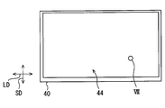
- the HUD device 100 As shown in FIG. 1, the HUD device 100 according to the first embodiment of the present disclosure is mounted on a vehicle 1 that is a kind of moving body and is housed in an instrument panel 2.
- the HUD device 100 projects image display light onto a windshield 3 as a projection member of the vehicle 1.
- HUD device 100 displays a virtual image so that a crew member of vehicles 1 can recognize visually. That is, the display light reflected by the windshield 3 reaches the occupant's eye point EP in the vehicle 1 and the occupant perceives the display light as a virtual image VI.
- the occupant can recognize various information displayed as the virtual image VI. Examples of various information displayed as the virtual image VI include vehicle state values such as vehicle speed and fuel remaining amount, or vehicle information such as road information and visibility assistance information.
- the windshield 3 of the vehicle 1 is formed in a plate shape with translucent glass or synthetic resin.
- the windshield 3 forms a projection surface 3a on which display light is projected in a smooth concave or flat shape.
- a combiner instead of the windshield 3, a combiner separate from the vehicle 1 may be installed in the vehicle 1, and an image may be projected onto the combiner.
- the HUD device 100 itself may include a combiner as a projection member.
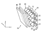
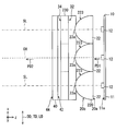
- the HUD device 100 includes an illumination light source unit 10, a condenser lens 20, a projection lens 30, an image display panel 40, and a light guide unit 50, which are housed and held in a housing 60.
- an image projection unit 19 is constituted by the illumination light source unit 10, the condenser lens 20, the projection lens 30, and the image display panel 40.
- Each element 10, 20, 30, 40 included in the image projection unit 19 is accommodated in a casing 19a having a light shielding property.
- the illumination light source unit 10 includes a light source circuit board 11 and a plurality of light emitting elements 12 as shown in FIGS.
- the light source circuit board 11 has a planar mounting surface 11a.
- the light emitting elements 12 are, for example, light emitting diode elements that generate little heat, and are arranged on the mounting surface 11a.
- Each light emitting element 12 is electrically connected to a power source through a wiring pattern on the mounting surface 11a. More specifically, each light emitting element 12 is formed by sealing a chip-like blue light emitting diode element with a yellow phosphor in which a yellow fluorescent agent is mixed with a synthetic resin having translucency. The yellow phosphor is excited by blue light emitted according to the amount of current from the blue light emitting diode element to emit yellow light, and pseudo white illumination light is emitted by mixing blue light and yellow light.
- the light emitting elements 12 are arranged in a grid pattern on the mounting surface 11a with two directions orthogonal to each other as the arrangement direction.
- the number of arranged light emitting elements 12 is, for example, a total of 15 of 3 ⁇ 5.
- the normal direction of the planar mounting surface 11a of the light source circuit board 11 is defined as the z direction.
- the direction with the larger number of arrangements, that is, five arrangement directions is defined as the x direction
- the direction with the smaller number of arrangements, that is, the three arrangement directions is defined as the y direction.
- each light emitting element 12 emits light with a predetermined light emission intensity distribution, and is arranged so that the light emission peak direction PD1 at which the light emission intensity is maximum is aligned with the z direction (see FIGS. 3 and 4). Therefore, in the present embodiment, the optical axis OA of the illumination light source unit 10 defined based on the configuration of the illumination light source unit 10 is defined as an axis along the z direction that is the emission peak direction PD1. More specifically, the optical axis OA passes through the middle light emitting element 12 located at the center of the illumination light source unit 10, and is defined as an axis along the z direction that is the light emission peak direction PD1. In other words, the illumination light source unit 10 emits illumination light in the direction along the optical axis OA by each light emitting element 12. Illumination light emitted from the illumination light source unit 10 enters the condenser lens 20.
- the condenser lens 20 is disposed between the illumination light source unit 10 and the projection lens 30.
- the condenser lens 20 condenses the illumination light from the illumination light source unit 10 side and emits it toward the projection lens 30.
- the condensing lens 20 is a lens array in which a plurality of convex lens elements 22 made of translucent synthetic resin or glass are arranged in an integrated manner.
- Each convex lens element 22 is a lens element provided in the same number as the light emitting elements 12 so as to be paired with each light emitting element 12 individually. That is, each convex lens element 22 has a total of 15 arrays of 3 ⁇ 5.
- the incident-side surface 20 a facing the illumination light source unit 10 is a single flat surface having a smooth flat shape common to the convex lens elements 22.
- condensing surfaces 23 provided individually for each convex lens element 22 are arranged on the exit-side surface 20 b facing the projection lens 30 in the condensing lens 20, condensing surfaces 23 provided individually for each convex lens element 22 are arranged.
- the condensing surfaces 23 have substantially the same shape between the convex lens elements 22, and each condensing surface 23 is formed into a smooth convex surface by curving into a convex shape protruding toward the projection lens 30. .
- the arrangement interval of the light emitting elements 12 arranged mutually is substantially equal to the arrangement interval of the surface vertices of the light collection surfaces 23 arranged mutually. Further, the distance between each light emitting element 12 and the surface vertex 23a of the condensing surface 23 of the convex lens element 22 forming a pair is substantially equal in each pair.
- the arrangement direction of the light emitting elements 12 and the arrangement direction of the convex lens elements 22 substantially coincide with each other, so that the condensing lens 20 is arranged so that its radial direction is substantially perpendicular to the optical axis OA (that is, the z direction). .
- each condensing surface 23 is a rotationally symmetric aspherical surface with respect to the surface vertex 23a.
- each condensing surface 23 is formed in a parabolic shape in the xz section (see FIG. 4), and is also formed in a parabolic shape in the yz section (see FIG. 3).
- the projection lens 30 is disposed between the illumination light source unit 10 and the image display panel 40, more strictly between the condenser lens 20 and the image display panel 40.
- the projection lens 30 projects illumination light incident from the illumination light source unit 10 side onto the image display panel 40.
- the projection lens 30 is a lens array in which a plurality of deflecting elements 30b made of translucent synthetic resin or glass are arranged in an integrated manner, and has a substantially flat plate shape as a whole. ing.
- the deflection elements 30b are arranged with each other along the radial direction DD of the projection lens 30.
- Each deflection element 30b can deflect the traveling direction of the illumination light by refraction at split lens surfaces 33 and 35, which will be described later.
- the projection lens 30 constitutes a plurality of deflection elements 30b arranged in each of the divided blocks 30a.
- a total of 36 6 ⁇ 6 deflection elements 30b corresponding to the number of division lens surfaces 33 and 35 to be described later are arranged in one division block 30a.
- the radial direction DD coincides with the extending direction perpendicular to the plate thickness direction.
- Such a projection lens 30 is tilted so that the thickness direction intersects the optical axis OA (that is, the z direction).
- the image display panel 40 is a liquid crystal panel using thin film transistors (TFTs), and is an active matrix type liquid crystal panel formed from a plurality of liquid crystal pixels 40a arranged in two directions, for example.
- TFTs thin film transistors
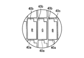
- the image display panel 40 has a rectangular shape having a longitudinal direction LD and a short direction SD.
- the liquid crystal pixels 40a are arranged in the longitudinal direction LD and the short direction SD, so that the display surface 44 that displays an image on the light guide unit 50 side also has a rectangular shape.
- a transmissive portion 40b provided so as to penetrate in the normal direction ND of the display surface 44 and a wiring portion 40c formed so as to surround the transmissive portion 40b are provided.
- the image display panel 40 has a flat plate shape by being formed by laminating a pair of polarizing plates and a liquid crystal layer sandwiched between the pair of polarizing plates.
- Each polarizing plate has a property of transmitting light polarized in a predetermined direction and absorbing light polarized in a direction perpendicular to the predetermined direction.
- the pair of polarizing plates has the predetermined direction orthogonal to each other. Has been placed.
- the liquid crystal layer can rotate the polarization direction of light incident on the liquid crystal layer according to the applied voltage by applying a voltage to each liquid crystal pixel 40a. By rotating the polarization direction, the ratio of light transmitted through the subsequent polarizing plate, that is, the transmittance can be changed.
- the image display panel 40 controls the transmittance of the illumination light for each liquid crystal pixel 40a with respect to the illumination light incident on the illumination target surface 42 which is the surface on the illumination light source unit 10 side. That is, the image display panel 40 displays an image by transmitting a part of the illumination light from the illumination light source unit 10 side and emitting it as display light from the display surface 44 that is the light guide unit 50 side surface.
- Adjacent liquid crystal pixels 40a are provided with color filters of different colors (for example, red, green, and blue), and various colors are realized by combining these color filters.
- the display surface 44 is formed so as to be able to reflect light incident on the image display panel 40 from the light guide unit 50 side, for example, using a mirror-like surface of a glass substrate in the image display panel 40.
- the illumination light is incident on the illumination target surface 42 of the image display panel 40 along the optical axis OA.
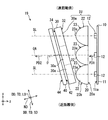
- the image display panel 40 is inclined so that the normal direction ND of the illumination target surface 42 and the display surface 44 intersects the optical axis OA.
- the image display panel 40 is inclined so that the longitudinal direction LD of the tangential direction TD of the display surface 44 is orthogonal to the optical axis OA, and the lateral direction SD is inclined with respect to the optical axis OA. Yes.
- the longitudinal direction LD is along the x direction.
- the image display panel 40 takes a posture rotated from the posture in which the normal direction of the display surface 44 is orthogonal to the optical axis OA, with the longitudinal direction LD (that is, the x direction) as the rotation axis.
- the crossing angle ⁇ in the normal direction ND of the display surface 44 with respect to the optical axis OA is, for example, about 10 to 25 degrees.
- the emission peak direction PD2 in which the emission intensity is the largest among the display light is not changed by the image display panel 40. It is generally along the axis OA. That is, the emission peak direction PD2 of the display light is different from the normal direction ND of the display surface 44. In this way, the image projection unit 19 projects display light onto the light guide unit 50.
- the light guide unit 50 guides display light from the image display panel 40 of the image projection unit 19 to the windshield 3.
- the light guide unit 50 of this embodiment includes a plane mirror 51 and a concave mirror 53. In the present embodiment, display light from the image display panel 40 first enters the plane mirror 51.
- the plane mirror 51 is formed by evaporating aluminum as the reflective surface 52 on the surface of a base material made of synthetic resin or glass.
- the reflecting surface 52 is formed in a smooth flat shape.
- the display light incident on the plane mirror 51 is reflected by the reflecting surface 52 toward the concave mirror 53.
- the concave mirror 53 is formed by evaporating aluminum as the reflective surface 54 on the surface of a base material made of synthetic resin or glass.
- the reflecting surface 54 is formed in a smooth concave shape by curving into a concave shape in which the center of the concave mirror 53 is concave.
- the display light incident on the concave mirror 53 is reflected toward the windshield 3 by the reflecting surface 54.
- a window 61 is provided in the housing 60 between the concave mirror 53 and the windshield 3.
- the window 61 is covered with a translucent dustproof cover 62. Therefore, the display light from the concave mirror 53 passes through the dust cover 62 and enters the windshield 3. Thus, the occupant can visually recognize the display light reflected by the windshield 3 as a virtual image VI.
- external light such as sunlight can pass through the windshield 3 and enter the window 61.
- a part of the external light incident on the window portion 61 is reverse to the display light, that is, is reflected in turn by the concave mirror 53 and the plane mirror 51 of the light guide portion 50, and is reflected on the display surface 44 of the image display panel 40.
- the normal direction ND of the display surface 44 intersects the optical axis OA, so that external light incident on the display surface 44 can be reflected in a direction different from the display light.
- the inclination direction or angle of the image display panel 40 is set so as to satisfy or close to the Scheimpflug condition in consideration of the arrangement angle of the plane mirror 51, the concave mirror 53, and the windshield 3. It is preferred that According to such an inclination direction and angle, it is possible to suppress the virtual image VI viewed from the eye point EP from being inclined and viewed.
- the projection lens 30 is also tilted in correspondence with the image display panel 40. Specifically, the projection lens 30 is inclined so that its radial direction DD matches the tangential direction TD of the display surface 44. As a result, as described above, the thickness direction of the projection lens 30 intersects the optical axis OA (that is, the z direction).
- the image display panel 40 and the projection lens 30 of the present embodiment are arranged so as to avoid interference with each other.
- the interference here includes optical interference in addition to spatial interference in which the image display panel 40 and the projection lens 30 collide with each other. If the distance between the image display panel 40 and the projection lens 30 is partially narrowed due to the angular difference in arrangement, moire fringes can be observed only in a part of the image. In such moire fringes, there is a concern that the boundary between the deflection elements 30b in the projection lens 30 described above is emphasized.
- the distance between the image display panel 40 and the projection lens 30 is constant.
- the image display panel 40 and the projection lens 30 are arranged in parallel to each other by making the distance between the image display panel 40 and the projection lens 30 constant.
- the shape of the projection lens 30 is adapted to such an inclined arrangement.
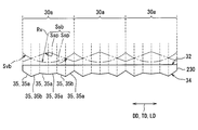
- the shape of the projection lens 30 will be described in detail with reference to FIGS.
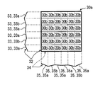
- a plurality of divided lens surfaces 33 are aligned with the boundary between adjacent deflection elements 30b as components of the deflection element 30b. Are formed in a striped state.
- the dividing direction of the dividing lens surface 33 on the incident-side surface 32 is along the short direction SD inclined by, for example, about 10 to 25 degrees from the y direction. Therefore, in the xz cross section, one divided lens surface 33 is formed across the deflection element 30b and the divided block 30a.
- Each divided lens surface 33 is arranged so that the component in the xz cross section in the normal direction thereof is along the optical axis OA, and the component in the yz cross section in the normal direction is intersected with the optical axis OA. Therefore, the incident side surface 32 is mainly configured to deflect the traveling direction of the illumination light in the yz section.
- a plurality of divided lens surfaces 35 are the boundaries between adjacent deflection elements 30 b as constituent elements of the deflection element 30 b. And is formed in a state of being divided into stripes.
- the dividing direction of the divided lens surface 35 on the exit side surface 34 is along the longitudinal direction LD (that is, the x direction). Therefore, in the yz section, one divided lens surface 35 is formed across the deflection element 30b and the divided block 30a.
- Each divided lens surface 35 is arranged so that the component in the yz section in the normal direction thereof is along the optical axis OA and the component in the xz section in the normal direction intersects the optical axis OA. Therefore, the emission side surface 34 is mainly configured to deflect the traveling direction of the illumination light in the xz section.
- the emission side surface 34 is configured to have substantially the same shape for each of the divided blocks 30a divided into five in accordance with the number of the light emitting elements 12 corresponding to the x direction.
- each approximate plane 35a and each anisotropic deflection plane 35b are formed as one divided region divided into regions with a predetermined division width Wa.
- the predetermined division width Wa is set to be substantially constant.
- the approximate plane 35 a is formed based on a virtual convex curved surface Svb defined as a virtual lens surface in the projection lens 30.
- the virtual convex curved surface Svb exhibits a smooth cylindrical surface shape by being curved in the xz cross section into a convex shape convex toward the image display panel 40 side.
- the approximate plane 35a is formed in a planar shape as an approximate plane obtained by linear interpolation of a plurality of coordinates extracted from the virtual convex curved surface Svb.
- the end coordinates Ce of the virtual convex curved surface Svb at the ends of the divided regions are employed as the plurality of coordinates, and the gradient of the approximate plane 35a is obtained by linear interpolation between the end coordinates Ce. It is prescribed.
- the virtual convex curved surface Svb appears on the emission side surface 34 in a state of being planar by partial approximation.
- the anisotropic deflection plane 35b is arranged in a state of being interposed between the approximate planes 35a.
- the anisotropic deflection plane 35b is formed based on a virtual inclined surface Ssb defined as a virtual lens surface in the projection lens 30.
- the virtual inclined surface Ssb is composed of a plurality of planar inclined surfaces Ssp that change in reverse gradient at locations corresponding to the surface vertices of the virtual convex curved surface Svb, and the gradient of each planar inclined surface Ssp is the virtual convex surface.
- the slope of the corresponding portion of the curved surface Svb is set to be opposite to the slope.
- six divided lens surfaces 35 are provided for one divided block 30a.
- the six divided lens surfaces 35 are arranged in the order of the approximate plane 35a, the anisotropic deflection plane 35b, the approximate plane 35a, the approximate plane 35a, the anisotropic deflection plane 35b, and the approximate plane 35a, and the boundary between the adjacent approximate planes 35a. Is a portion corresponding to the surface vertex of the virtual convex curved surface Svb. Accordingly, since the gradient is switched to the reverse gradient for each divided lens surface 35, the projection lens 30 is maintained in a substantially flat plate shape even when the boundaries between the divided lens surfaces 35 are connected without a step.
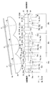
- each divided lens surface 33 on the incident side surface 32 will be described.
- the incident-side surface 32 is configured in a different shape for each divided block 30 a that is divided into three according to the number of light emitting elements 12 corresponding to the x direction.
- a plurality of approximate planes 33a and a plurality of anisotropic deflection planes 33b are provided as the divided lens surface 33 in the same manner as the exit side surface 34.
- Each approximate plane 33a and each anisotropic deflection plane 33b are formed as one divided region divided into regions with a predetermined division width Wa.
- the predetermined division width Wa is set to be substantially constant.
- the approximate plane 33 a is formed based on a virtual convex curved surface Sva defined as a virtual lens surface in the projection lens 30.
- the virtual convex curved surface Sva exhibits a smooth cylindrical surface shape by being curved in the yz section into a convex shape that is convex toward the condenser lens 20 side.
- the approximate plane 33a is formed in a planar shape as an approximate plane obtained by linear interpolation of a plurality of coordinates extracted from the virtual convex curved surface Sva.
- the end coordinates Ce of the virtual convex curved surface Sva at the ends of the divided areas are adopted as the plurality of coordinates, and the gradient of the approximate plane 33a is obtained by linear interpolation between the end coordinates Ce. It is prescribed.
- the virtual convex curved surface Sva appears on the incident side surface 32 in a state of being flat by partial approximation.
- the end coordinates Ce are shown in a part of FIG. 9 and are omitted in FIG. 8 because they are the same.
- the anisotropic deflection plane 33b is arranged in a state of being interposed between the approximate planes 33a.
- the anisotropic deflection plane 33 b is formed based on a virtual inclined surface Ssa defined as a virtual lens surface in the projection lens 30.
- the virtual inclined surface Ssa is composed of a plurality of planar inclined surfaces Ssp that change in reverse gradient at locations corresponding to the surface vertices of the virtual convex curved surface Sva in the yz section.
- the gradient of each planar inclined surface Ssp is the virtual convex surface
- the slope of the corresponding portion of the curved surface Sva is set so as to be opposite to the slope.
- a part of the virtual inclined surface Ssa is extracted and appears on the exit-side surface 34.
- six divided lens surfaces 33 are provided for one divided block 30a.
- the six divided lens surfaces 33 are arranged in the order of the approximate plane 33a, the anisotropic deflection plane 33b, the approximate plane 33a, the approximate plane 33a, the anisotropic deflection plane 33b, and the approximate plane 33a, and the boundary between the adjacent approximate planes 33a. Is a portion corresponding to the surface vertex of the virtual convex curved surface Sva. Therefore, since the gradient is switched to the reverse gradient for each divided lens surface 33, the projection lens 30 is maintained in a substantially flat plate shape even when the boundaries between the divided lens surfaces 33 are connected without a step.
- the incident-side surface 20a has a different gradient of the approximate plane 33a for each divided block 30a.
- the curvature radius Rv of the base virtual convex curved surface Sva is different. Therefore, the gradient of the approximate plane 33a is different for each divided block 30a.
- the distance from the short-distance side where the distance to the illumination light source unit 10 is short is directed to the long-distance side where the distance from the illumination light source unit 10 is long.
- the radius of curvature Rv of the virtual convex curved surface Sva of each divided block 30a changes so as to be small.
- the curvature radii are Rv1, Rv2, and Rv3 in order from the divided block 30a on the short distance side, Rv1 ⁇ Rv2 ⁇ Rv3. Therefore, the gradient of the approximate plane 33a in the divided block 30a on the long distance side is relatively larger than that on the short distance side.
- the gradient of the anisotropic deflection plane 33b is set to be substantially equal in each divided block 30a.
- a location on the approximate plane 33a corresponding to the surface vertex of the virtual convex curved surface Sva extends from the surface vertex 23a of the corresponding condensing surface 23 of the condensing lens 20 along the optical axis OA.
- the illumination light source unit 10, the condensing lens 20, and the projection lens 30 in the present embodiment can be understood as an arrangement of such illumination units IU.
- the illumination light incident on the approximate plane 33a is deflected in the traveling direction so as to approach the corresponding straight line SL.
- the deflection amount by which the illumination light is deflected depends on the gradient of each approximate plane 33a with respect to the radial direction DD.
- the condensing lens is obtained from the radius of curvature of the condensing surface 23 of the condensing lens 20 and the radii of curvature Rv of the virtual convex curved surfaces Sva and Svb that form the basis of the approximate planes 33a and 35a of the projection lens 30. 20 and the projection focus of the projection lens 30 can be defined.
- the position of the synthetic focus and the position of the illumination light source unit 10 can be close to each other, the illumination lights refracted by the different approximate planes 33a are close to each other in the traveling direction component in the yz section. Deflected.
- the illumination lights refracted by the different approximate planes 35a are deflected so that the components in the traveling direction in the xz cross section approach each other. Accordingly, the illumination lights refracted by the different deflecting elements 30b are converted into a parallel light flux before the projection lens 30 is incident.
- a convex lens element is obtained from the radius of curvature of the condensing surface 23 in each illumination unit IU and the radius of curvature Rv of the virtual convex curved surfaces Sva and Svb that are the basis of the approximate planes 33a and 35a in the divided block 30a.
- the composite focus of 22 and the divided block 30a can be defined.
- the position of this synthetic focus can be defined for each illumination unit IU.
- the distance between the divided block 30a and the light emitting element 12 is different in each illumination unit IU on the yz section.
- the curvature radius Rv of the virtual convex curved surface Sva on which the approximate plane 33a is based is made different for each divided block 30a, so that the position of the light-emitting element 12 corresponding to the position of the synthetic focal point. This makes it possible to set the position closer.
- the anisotropic deflection plane 35b disposed adjacent to the approximate planes 33a and 35a deflects illumination light in a different direction from the approximate planes 33a and 35a that are separated from each other by refraction.
- a part of the illumination light is mixed with the illumination light that is refracted on the approximate planes 33a and 35a by refraction on the anisotropic deflection planes 33b and 35b. Therefore, it is possible to suppress the display light emitted from the display surface 44 of the image display panel 40 from being concentrated and emitted in the emission peak direction PD2.
- each deflection element 30b is exhibited by the combination of the striped lens surfaces 33 and 35 extending substantially orthogonal to each other on both surfaces 32 and 34 of the projection lens 30.
- the base in the deflection of the illumination light of each deflecting element 30b is determined by the gradient in the yz section of the split lens surface 33 on the incident side surface 32 and the gradient in the xz section of the split lens surface 35 on the exit side surface 34.
- the direction and amount of deflection can be determined.
- the deflection amount can be expressed by, for example, an angle difference between an incident angle and an emission angle of illumination light to one deflection element 30b.
- the average value of the deflection amount of each deflection element 30b constituting each divided block 30a changes stepwise from the short distance side toward the long distance side.
- the average value of the deflection amount of each deflection element 30b constituting the divided block 30a is larger on the far side.
- the average value of the deflection amounts of the deflection elements 30b disposed on the short distance side and the average value of the deflection amounts of the deflection elements 30b disposed on the long distance side are mutually different. Is different.
- the average value of the deflection amounts of the deflection elements 30b arranged on the long distance side is larger than the average value of the deflection amounts of the deflection elements 30b arranged on the short distance side.
- the normal direction ND of the display surface 44 is shifted with respect to the optical axis OA.
- the projection lens 30 is tilted so that the radial direction DD is aligned with the tilted image display panel 40.
- the projection lens 30 and the image display are suppressed while suppressing interference between the projection lens 30 and the image display panel 40.
- Generation of a dead space between the panel 40 can be suppressed. Therefore, an increase in the physique of the HUD device 100 can be suppressed, and the HUD device 100 that is highly mountable on the vehicle 1 as a moving body can be provided.
- the image display panel 40 and the projection lens 30 are arranged in parallel to each other. In this way, the distance between the projection lens 30 and the image display panel 40 can be minimized while suppressing interference between the projection lens 30 and the image display panel 40.
- the condensing lens 20 disposed between the illumination light source unit 10 and the projection lens 30 has a condensing surface 23 that is curved in a convex shape protruding toward the projection lens 30 side. . Therefore, when the projection lens 30 is tilted according to the image display panel 40, the end of the projection lens 30 that is close to the condenser lens 20 side is on the side of the condenser surface 23 along the curve of the condenser surface 23. It will be placed around the space. For this reason, the distance from the illumination light source unit 10 to the tip of the image display panel 40 is increased while obtaining the condensing effect of the condensing lens 20 and avoiding interference between the projection lens 30 and the condensing lens 20. Can be suppressed. Therefore, an increase in the physique of the HUD device 100 can be suppressed, and the HUD device 100 with high mountability on the vehicle 1 can be provided.
- the projection lens 30 includes a plurality of deflecting elements 30b arranged in the radial direction DD and deflecting the traveling direction of the illumination light.
- the values are different from each other.
- the average value of the deflection amount of the deflection element 30b constituting each divided block 30a changes stepwise from the short distance side toward the long distance side. If it does in this way, each illumination light corresponding to each light emitting element 12 will receive the deflection
- the projection lens 30 has a plurality of approximate planes 33a or 35a that are formed in a planar shape by partial approximation of the virtual convex curved surface Sva or Svb as a component of the deflection element 30b. . Since each approximate plane 33a or 35a is planar but based on a common virtual convex curved surface Sva or Svb, each illumination light incident on a different approximate plane 33a or 35a is applied to the virtual convex curved surface Sva or Svb. Since the traveling direction is deflected by a corresponding amount of deflection, an action substantially similar to the light collecting action can occur between the illumination lights. Therefore, it is possible to easily form the projection lens 30 and to suppress the increase in the size of the HUD device 100 and suitable illumination for the tilted image display panel 40.
- the image projection unit 19 having the image display panel 40 in which the normal direction ND of the display surface 44 intersects the optical axis OA projects display light onto the light guide unit 50.
- the image projection unit 19 even if external light such as sunlight enters the image display panel 40 in a direction opposite to the display light through the light guide 50, the external light is incident on the display surface 44. It is particularly suitable for use in the HUD device 100 because it is suppressed from being reflected and visually recognized together with the display light.
- the projection lens 30 is tilted so that the radial direction DD is aligned with the tilted image display panel 40. According to the inclination of both the projection lens 30 and the image display panel 40, since there is no or little difference in arrangement angle, the projection lens 30 and the image display are suppressed while suppressing interference between the projection lens 30 and the image display panel 40. Generation of a dead space between the panel 40 can be suppressed. Therefore, since the increase in the physique of the image projection unit 19 can be suppressed, the mountability of the HUD device 100 on the vehicle 1 can be improved.
- the second embodiment of the present disclosure is a modification of the first embodiment.
- the second embodiment will be described with a focus on differences from the first embodiment.
- the plurality of light emitting elements 12 are arranged in a grid pattern with one direction on the mounting surface 11 a as the arrangement direction.
- the number of arranged light emitting elements 12 is, for example, all three of 1 ⁇ 3.
- the normal direction of the planar mounting surface 11a of the light source circuit board 11 is defined as the z direction.
- the direction with the larger number of arrangements, that is, the three arrangement directions are defined as the x direction
- the direction with the smaller number of arrangements, that is, one arrangement direction (in this embodiment, substantially Direction) is defined as the y direction.
- Each light emitting element 12 is arranged with the light emission peak direction PD1 aligned with the z direction, as in the first embodiment.
- the optical axis OA of the illumination light source unit 210 passes through the middle light emitting element 12 located at the center of the illumination light source unit 210 and is defined as an axis along the z direction that is the emission peak direction PD1.
- each convex lens element 22 is arranged in a total of three 1 ⁇ 3.
- the incident-side surface 20a is a single flat surface similar to that of the first embodiment.
- the condensing surface 223 provided for each convex lens element 22 is arranged on the exit side surface 20b.
- each condensing surface 223 has the same arrangement and arrangement as in the first embodiment, but its detailed shape is different from that in the first embodiment. Specifically, each condensing surface 223 is an anamorphic surface in which the curvature radius in the x direction and the curvature radius in the y direction are different from each other. In the present embodiment, the curvature radius in the x direction is smaller than the curvature radius in the y direction at the surface vertex 23a of each condensing surface 223 and in the vicinity thereof.
- the vicinity of the surface vertex 23a in this embodiment refers to a range in which the distance from the surface vertex 23a is about half the value of the diameter of the condensing surface 223, for example.
- each condensing surface 223 is formed in a parabolic shape (see FIG. 11).
- each condensing surface 223 is formed in an arc shape (particularly in a semicircular shape in the present embodiment) (see FIG. 10).
- the projection lens 230 is a lens array in which a plurality of deflecting elements 30b made of translucent synthetic resin or glass are arranged and integrated with each other. It has a substantially flat plate shape.
- the same divided block 30a as in the first embodiment can be defined.
- a total of three 1 ⁇ 3 divided blocks 30a divided into three corresponding to the number of arranged light emitting elements 12 can be defined.
- the longitudinal direction LD along the x direction of the tangential direction TD of the display surface 44 is orthogonal to the optical axis OA and the short direction SD is relative to the optical axis OA, as in the first embodiment.
- the projection lens 230 is also inclined.
- the image display panel 40 and the projection lens 230 are arranged in parallel to each other.
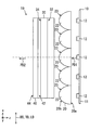
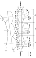
- the condensing lens 220 and the projection lens 230 are partially overlapped in the vertical direction perpendicular to the optical axis OA (in this embodiment, the y direction on the yz section). . This is because one end portion of the projection lens 230 is disposed in the lateral space of the condensing surface 223 due to the inclined arrangement of the projection lens 230.
- the shape of the projection lens 230 is not particularly adapted to such an inclined arrangement.
- the shape of the projection lens 230 will be described in detail.
- a plurality of divided lens surfaces 33 are divided into stripes in accordance with the boundaries between adjacent deflection elements 30b as constituent elements of the deflection element 30b. It is formed in a state.
- the dividing direction of the dividing lens surface 33 on the incident-side surface 32 is along the short direction SD inclined by, for example, about 10 to 25 degrees from the y direction. Therefore, in the xz cross section, one divided lens surface 33 is formed across the deflection element 30b and the divided block 30a.
- each divided lens surface 33 is a divided convex surface 233c divided into a convex Fresnel lens shape.
- the divided convex surface 233c is formed based on one virtual convex curved surface Svc defined as a virtual lens surface in the projection lens 230.
- the virtual convex curved surface Svc has a smooth cylindrical surface shape by being curved in the yz section into a convex shape convex toward the condenser lens 220 side. Therefore, the incident side surface 32 is mainly configured to deflect the traveling direction of the illumination light in the yz section.
- the emission side surface 34 has a reduced number of divided blocks 30 a corresponding to the number of light emitting elements 12 arranged, but the configuration in each divided block 30 a is This is the same as in the first embodiment.
- a position on the divided convex surface 233c and a position on the approximate plane 35a corresponding to the surface vertices of the virtual convex curved surfaces Svc and Svb are the surface vertices 23a of the corresponding condensing surface 223 in the condensing lens 220.
- the projection lens 230 is inclined so that the radial direction DD matches the tangential direction TD of the display surface 44, it is possible to achieve the operational effects according to the first embodiment. It becomes.
- the condensing lens 220 and the projection lens 230 are partially overlapped in the vertical direction perpendicular to the optical axis OA. The dead space between the two can be reduced.
- the third embodiment of the present disclosure is a modification of the first embodiment.
- the third embodiment will be described with a focus on differences from the first embodiment.
- the projection lens 330 according to the third embodiment is also adapted to the inclined arrangement.
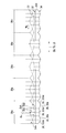
- the shape of the projection lens 330 will be described in detail.
- a plurality of divided lens surfaces 33 are divided into stripes in accordance with the boundaries of adjacent deflection elements 30b as constituent elements of the deflection elements 30b. It is formed with.
- the dividing direction of the dividing lens surface 33 on the incident side surface 32 is along the short direction SD inclined by, for example, about 10 to 25 degrees from the y direction.
- Each divided lens surface 33 is arranged such that the component in the yz section in the normal direction thereof is along the optical axis OA.
- the incident side surface 32 is mainly configured to deflect the traveling direction of the illumination light in the yz section.
- a plurality of divided lens surfaces 35 are divided into stripes in accordance with the boundaries of the deflection element 30b as components of the deflection element 30b. It is formed with.
- the splitting direction of the split lens surface 35 on the exit side surface 34 is along the longitudinal direction LD (that is, the x direction) as in the first embodiment.
- Each of the divided lens surfaces 35 is disposed so that the component in the xz cross section in the normal direction is along the optical axis OA.
- the exit side surface 34 is mainly configured to deflect the traveling direction of the illumination light in the xz section.
- the approximate planes 33a and 35a of the first embodiment of the divided lens surfaces 33 and 35 are replaced with convex curved surfaces 333d and 335d that are curved in a convex shape.
- the convex curved surfaces 333d and 335d are formed based on virtual convex curved surfaces Sva and Svb defined as virtual lens surfaces in the projection lens 330.
- the virtual convex curved surfaces Sva and Svb are the same as those in the first embodiment.
- the convex curved surfaces 333d and 335d do not approximate the virtual convex curved surfaces Sva and Svb, and are extracted from the virtual convex curved surfaces Sva and Svb as they are, so that they appear on the incident side surface 32 and the emission side surface 34. I'm out.
- the two approximate planes 33a or 35a in the first embodiment are replaced with one convex curved surface 333d or 335d, so that the division width Wa is another division. It is twice the area.
- the curvature radius Rv of the virtual convex curved surface Svb on the exit side surface 34 is set to be substantially equal between the divided blocks 30a. Therefore, the emission side surface 34 is configured to have substantially the same shape for each of the divided blocks 30a divided into five in accordance with the number of the light emitting elements 12 corresponding to the x direction.
- the incident-side surface 32 is configured in a different shape for each of the divided blocks 30a divided into three according to the number of arrangement of the light emitting elements 12 corresponding to the x direction.
- the radius of curvature Rv of the virtual convex curved surface Sva differs among the divided blocks 30a.
- the distance from the short-distance side where the distance to the illumination light source unit 10 is short is directed to the long-distance side where the distance from the illumination light source unit 10 is long. Accordingly, the radius of curvature Rv of the virtual convex curved surface Sva of each divided block 30a changes so as to decrease stepwise.
- each convex curved surface 333d changes in a stepwise manner from the short distance side toward the long distance side. Accordingly, the gradient of the convex curved surface 333d is different for each divided block 30a, and the gradient of the convex curved surface 333d in the divided block 30a on the far distance side is relatively larger than that on the short distance side.
- the gradient of the anisotropic deflection plane 33b is set to be substantially equal in each divided block 30a, as in the first embodiment.
- the projection lens 330 is inclined so that the radial direction DD is aligned with the tangential direction TD of the display surface 44, it is possible to achieve the operational effects according to the first embodiment. It becomes.
- the projection lens 30 has convex curved surfaces 333d and 335d that are curved in a convex shape as components of the deflection element 30b. Since the illumination light incident on the convex curved surfaces 333d and 335d is subjected to a condensing function, it is possible to realize the suppression of the physique increase of the HUD device 100 and the suitable illumination to the tilted image display panel 40. Can do.
- the curvature radii Rv1 to Rv3 of the convex curved surfaces 333d change in a stepwise manner from the short distance side to the long distance side of the projection lens 330. If it does in this way, each illumination light which passed each convex-shaped curved surface 333d will receive the condensing effect
- the light emitting element 12 may be decentered toward the center of the illumination light source unit 10 with respect to the arrangement pitch of the convex lens elements 22 as shown in FIG. In this case, the amount of eccentricity of each light emitting element 12 may be set asymmetrically across the central light emitting element 12.
- the light emitting element 12 is not arranged on a straight line but is arranged so as to match the position of the synthetic focus of the convex lens element 22 and the divided block 30a. Also good.
- the light source circuit board 11 is a flexible board with a mounting surface 11 a having a curved curved surface, and a plurality of light emitting elements 12 are arranged in a curved shape. Therefore, the light emitting elements 12 may be arranged asymmetrically with the center in between.
- the condenser lens 20 may not be provided.
- the radius of curvature Rv of the virtual convex curved surface Sva of each divided block 30a gradually increases from the short distance side to the long distance side. You may change so that it may become large.
- the curvature radii are Rv1, Rv2, Rv3 in order from the divided block 30a on the short distance side, Rv1> Rv2> Rv3.
- the magnitude relationship between the radius of curvature Rv on the near side and the far side may vary depending on various design conditions such as the presence / absence of the condenser lens 20 and the focal length and arrangement of the condenser lens 20.
- the division width may be set so that the sag amount of each of the divided lens surfaces 33 and 35 is substantially constant.
- deviation element 30b can be set arbitrarily.
- the projection lens 30 instead of making the average value of the deflection amount of the deflection element 30b disposed on the short distance side different from the average value of the deflection amount of the deflection element 30b disposed on the long distance side.
- the direction from the surface vertex of the virtual convex curved surface Sva toward the center of curvature may be different between the short distance side and the long distance side.
- the approximate plane 33a is formed in a flat shape by partial approximation of the virtual convex curved surface Sva, for example, the contact of the virtual convex curved surface Sva at the midpoint of the divided region is used. It may be formed by extracting a plane.
- the condensing surface 23 may be formed in a spherical shape.
- the projection lens 30 may have a shape in which the shapes of the incident side surface 32 and the emission side surface 34 are interchanged.
- the projection lens 30 may have a slight angle difference with the image display panel 40 as long as the projection lens 30 is inclined so as to match the radial direction DD with the tangential direction TD of the display surface 44.
- the projection lens 30 may not have a plurality of deflection elements 30b arranged along the radial direction DD. Specifically, even in the case of a convex lens having a single lens surface on each of the incident side surface 32 and the emission side surface 34, the present disclosure can be applied if the radius of curvature of the lens surface is set to be large. it can.
- the present disclosure may be applied to various moving bodies (transportation equipment) such as ships or airplanes other than the vehicle 1.
- the above-described head-up display device is mounted on the moving body 1 and projects an image display light onto the projection member 3 to display a virtual image so that the occupant can visually recognize the image.
- the head-up display device includes illumination light source units 10 and 210, an image display panel 40, and projection lenses 30, 230, and 330.
- the illumination light source units 10 and 210 emit illumination light.
- the image display panel 40 displays an image by allowing illumination light from the illumination light source unit side to pass through and exiting from the display surface 44 as display light.
- the projection lenses 30, 230, and 330 are disposed between the illumination light source unit and the image display panel, and project illumination light from the illumination light source unit side onto the image display panel.
- the image display panel is inclined so that the normal direction ND of the display surface intersects the optical axis OA of the illumination light source unit.
- the projection lens is tilted so that the radial direction DD of the projection lens matches the tangential direction TD of the display surface.
- the normal direction of the display surface is shifted with respect to the optical axis.
- the projection lens is inclined so that the radial direction is aligned with the inclined image display panel. According to the inclination of both the projection lens and the image display panel, since there is no or small angular difference in arrangement, the interference between the projection lens and the image display panel is suppressed, and the projection lens and the image display panel are Generation of dead space can be suppressed. Therefore, an increase in the physique of the HUD device can be suppressed, and a HUD device that is highly mountable on a moving body can be provided.
- the above-described head-up display device 100 is mounted on the moving body 1 and projects an image display light onto the projection member 3 to display a virtual image so that the occupant can visually recognize the image.
- the image projection unit 19 projects the display light onto the light guide 50 that guides the display light to the projection member.
- the image projection unit 19 includes illumination light source units 10 and 210, an image display panel 40, and projection lenses 30, 230, and 330.
- the illumination light source units 10 and 210 emit illumination light.
- the image display panel 40 displays an image by allowing illumination light from the illumination light source unit side to pass through and exiting from the display surface 44 as display light.
- the projection lenses 30, 230, and 330 are disposed between the illumination light source unit and the image display panel, and project illumination light from the illumination light source unit side onto the image display panel.
- the image display panel is inclined so that the normal direction ND of the display surface intersects the optical axis OA of the illumination light source unit.
- the projection lens is inclined so that the radial direction DD of the projection lens matches the tangential direction TD of the display surface.
- an image projection unit having an image display panel in which the normal direction of the display surface intersects the optical axis projects display light onto the light guide unit.
- an image projection unit even if external light such as sunlight enters the image display panel in a direction opposite to the display light through the light guide unit, the external light is reflected on the display surface. Since it is suppressed that it is visually recognized together with display light, it is particularly suitable for use in a HUD device.
- the projection lens is tilted so as to align the radial direction with the tilted image display panel.
- the inclination of both the projection lens and the image display panel since there is no or small angular difference in arrangement, the interference between the projection lens and the image display panel is suppressed, and the projection lens and the image display panel are Generation of dead space can be suppressed. Therefore, since the increase in the size of the image projection unit can be suppressed, the mountability of the HUD device on the moving body can be improved.
Landscapes
- Physics & Mathematics (AREA)
- General Physics & Mathematics (AREA)
- Optics & Photonics (AREA)
- Engineering & Computer Science (AREA)
- Chemical & Material Sciences (AREA)
- Nonlinear Science (AREA)
- Combustion & Propulsion (AREA)
- Transportation (AREA)
- Mechanical Engineering (AREA)
- Crystallography & Structural Chemistry (AREA)
- Instrument Panels (AREA)
- Liquid Crystal (AREA)
Abstract
ヘッドアップディスプレイ装置は、移動体(1)に搭載され、投影部材(3)へ画像の表示光を投影することにより、画像を乗員により視認可能に虚像表示する。照明光源部(10,210)は、照明光を発する。画像表示パネル(40)は、照明光源部側からの照明光を通過させ、表示光として表示面(44)から射出することで画像を表示する。投射レンズ(30,230,330)は、照明光源部と画像表示パネルとの間に配置され、照明光源部側からの照明光を画像表示パネルに投射する。画像表示パネルは、照明光源部の光軸(OA)に対して表示面の法線方向(ND)が交差するように、傾斜配置される。投射レンズは、投射レンズの径方向(DD)を表示面の接線方向(TD)に合わせるように、傾斜配置されている。
Description
本出願は、2016年5月18日に出願された日本出願番号2016-99852号に基づくもので、ここにその記載内容を援用する。
本開示は、移動体に搭載され、画像を乗員により視認可能に虚像表示するヘッドアップディスプレイ装置に関する。
従来、画像を乗員により視認可能に虚像表示するヘッドアップディスプレイ装置(以下、HUD装置を略称とする)が知られている。特許文献1に開示のHUD装置は、照明光源部、画像表示パネル、及び投射レンズを備えている。照明光源部は、照明光を発する。画像表示パネルは、照明光源部側からの照明光を通過させ、表示光として表示面から射出することで画像を表示する。投射レンズは、照明光源部と画像表示パネルとの間に配置され、照明光源部側からの照明光を画像表示パネルに投射する。
特許文献1において画像表示パネルは、照明光源部の光軸と表示面の法線方向とが一致するように、配置されている。また、投射レンズは、光軸と当該投射レンズの径方向とが直交するように、配置されている。
さて、本発明者は、画像表示パネルを、光軸に対して表示面の法線方向が交差するように、傾斜配置することを考えた。傾斜した画像表示パネルによれば、例えば太陽光等の外光が表示光とは逆行して画像表示パネルに入射したとしても、表示面の法線方向が交差しているので、当該外光が当該表示面に反射されて表示光と一緒に視認されることが抑制される。
その一方で、特に傾斜した画像表示パネルに照明光を投射する投射レンズが、その径方向を光軸と直交させて配置されたHUD装置では、以下の特有の問題が発生することを、本発明者は見出した。具体的に、投射レンズと画像表示パネルとの互いの干渉を避けて光路上に配置すると、投射レンズと画像表示パネルとの間隔が配置の角度差によって一部広くなってしまい、投射レンズと画像表示パネルとの間にデッドスペースが発生し得る。その結果、例えば照明光源部から画像表示パネルの先端までの距離の増大により、HUD装置の体格が増大する。すなわち、HUD装置の移動体への搭載性が低下してしまうのである。
本開示は、移動体への搭載性が高いHUD装置を提供することを目的とする。
本開示の第一の態様におけるヘッドアップディスプレイ装置は、移動体に搭載され、投影部材へ画像の表示光を投影することにより、前記画像を乗員により視認可能に虚像表示する、前記ヘッドアップディスプレイ装置は、照明光を発する照明光源部を、備える。前記ヘッドアップディスプレイ装置は、前記照明光源部側からの前記照明光を通過させ、前記表示光として表示面から射出することで前記画像を表示する画像表示パネルを、更に備える。前記ヘッドアップディスプレイ装置は、 前記照明光源部と前記画像表示パネルとの間に配置され、前記照明光源部側からの前記照明光を前記画像表示パネルに投射する投射レンズを、更に備える。前記画像表示パネルは、前記照明光源部の光軸に対して前記表示面の法線方向が交差するように、傾斜配置される。前記投射レンズは、前記投射レンズの径方向を前記表示面の接線方向に合わせるように、傾斜配置されている。
本開示の第二の態様におけるヘッドアップディスプレイ装置は、移動体に搭載され、投影部材へ画像の表示光を投影することにより、前記画像を乗員により視認可能に虚像表示する。前記ヘッドアップディスプレイ装置において、画像投射ユニットは、前記表示光を前記投影部材へ導光する導光部へと、前記表示光を投射する。前記画像投射ユニットは、照明光を発する照明光源部を、備える。前記画像投射ユニットは、前記照明光源部側からの前記照明光を通過させ、前記表示光として表示面から射出することで前記画像を表示する画像表示パネルを、更に備える。前記画像投射ユニットは、前記照明光源部と前記画像表示パネルとの間に配置され、前記照明光源部側からの前記照明光を前記画像表示パネルへ投射する投射レンズを、更に備える。前記画像表示パネルは、前記照明光源部の光軸に対して前記表示面の法線方向が交差するように、傾斜配置される。前記投射レンズは、前記投射レンズの径方向を前記表示面の接線方向に合わせるように、傾斜配置されている。
本開示についての上記目的およびその他の目的、特徴や利点は、添付の図面を参照しながら下記の詳細な記述により、より明確になる。その図面は、
第1実施形態におけるHUD装置の車両への搭載状態を示す模式図であり、
第1実施形態における画像投射ユニットを模式的に示す斜視図であり、
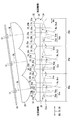
第1実施形態における画像投射ユニットを示す図であって、yz断面を模式的に示す断面図であり、
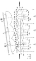
第1実施形態における画像投射ユニットを示す図であって、xz断面を模式的に示す断面図であり、
第1実施形態における投射レンズの部分正面図であって、1つの分割ブロック中の偏向素子を説明するための図であり、
第1実施形態における画像表示パネルを表示面の法線方向に沿って見た図であり、
図5のVII部を拡大して示す拡大図であり、
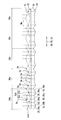
第1実施形態における投射レンズの入射側表面を説明するための図であり、
第1実施形態における投射レンズの射出側表面を説明するための図であり、
第2実施形態における画像投射ユニットを示す図であって、yz断面を模式的に示す断面図であり、
第2実施形態における画像投射ユニットを示す図であって、xz断面を模式的に示す断面図であり、
第2実施形態における投射レンズの入射側表面を説明するための図であり、
第2実施形態における投射レンズの射出側表面を説明するための図であり、
第3実施形態における投射レンズの入射側表面を説明するための図であり、
第3実施形態における投射レンズの射出側表面を説明するための図であり、
変形例1における図8に対応する図であり、
変形例2における図8に対応する図であり、また
変形例3,4における図8に対応する図である。
以下、本開示の複数の実施形態を図面に基づいて説明する。なお、各実施形態において対応する構成要素には同一の符号を付すことにより、重複する説明を省略する場合がある。各実施形態において構成の一部分のみを説明している場合、当該構成の他の部分については、先行して説明した他の実施形態の構成を適用することができる。また、各実施形態の説明において明示している構成の組み合わせばかりではなく、特に組み合わせに支障が生じなければ、明示していなくても複数の実施形態の構成同士を部分的に組み合せることができる。
(第1実施形態)
図1に示すように、本開示の第1実施形態によるHUD装置100は、移動体の一種である車両1に搭載され、インストルメントパネル2内に収容されている。HUD装置100は、車両1の投影部材としてのウインドシールド3へ画像の表示光を投影する。これにより、HUD装置100は、画像を車両1の乗員により視認可能に虚像表示する。すなわち、ウインドシールド3に反射される表示光が、車両1の室内において乗員のアイポイントEPに到達し、乗員が当該表示光を虚像VIとして知覚する。そして、乗員は、虚像VIとして表示される各種情報を認識することができる。虚像VIとして表示される各種情報としては、例えば、車速、燃料残量等の車両状態値、又は道路情報、視界補助情報等の車両情報が挙げられる。
図1に示すように、本開示の第1実施形態によるHUD装置100は、移動体の一種である車両1に搭載され、インストルメントパネル2内に収容されている。HUD装置100は、車両1の投影部材としてのウインドシールド3へ画像の表示光を投影する。これにより、HUD装置100は、画像を車両1の乗員により視認可能に虚像表示する。すなわち、ウインドシールド3に反射される表示光が、車両1の室内において乗員のアイポイントEPに到達し、乗員が当該表示光を虚像VIとして知覚する。そして、乗員は、虚像VIとして表示される各種情報を認識することができる。虚像VIとして表示される各種情報としては、例えば、車速、燃料残量等の車両状態値、又は道路情報、視界補助情報等の車両情報が挙げられる。
車両1のウインドシールド3は、透光性のガラスないしは合成樹脂により板状に形成されている。ウインドシールド3は、表示光が投影される投影面3aを滑らかな凹面状又は平面状に形成している。なお、投影部材として、ウインドシールド3の代わりに、車両1と別体となっているコンバイナを車両1内に設置して、当該コンバイナに画像を投影するものであってもよい。また、HUD装置100自体が、投影部材としてのコンバイナを備えていてもよい。
このようなHUD装置100の具体的構成を、図1~9に基づいて、以下に説明する。HUD装置100は、照明光源部10、集光レンズ20、投射レンズ30、画像表示パネル40、導光部50を備えており、これらはハウジング60に収容され、保持されている。
ここで、図1,2に示すように、照明光源部10、集光レンズ20、投射レンズ30及び画像表示パネル40により、画像投射ユニット19が構成されている。画像投射ユニット19が備える各要素10,20,30,40は、遮光性を有するケーシング19aに収容されている。
照明光源部10は、図2~4に示すように、光源用回路基板11及び複数の発光素子12を有している。光源用回路基板11は、平面状の実装面11aを有している。各発光素子12は、例えば発熱の少ない発光ダイオード素子であり、実装面11a上に互いに配列されている。各発光素子12は、実装面11a上の配線パターンを通じて、電源と電気的に接続されている。より詳細に、各発光素子12は、チップ状の青色発光ダイオード素子を、透光性を有する合成樹脂に黄色蛍光剤を混合した黄色蛍光体により封止することにより形成されている。青色発光ダイオード素子から電流量に応じて発せられる青色光により、黄色蛍光体が励起されて黄色光を発光し、青色光と黄色光との混合により疑似白色の照明光が発せられる。
本実施形態において、各発光素子12は、実装面11a上において互いに直交する2方向を配列方向として格子状に配列されている。各配列方向において、発光素子12の配列個数は、例えば3×5の全15個となっている。
また本実施形態において、光源用回路基板11の平面状の実装面11aの法線方向をz方向と定義する。そして、実装面11aに沿った方向のうち、配列個数が多い方、すなわち5個の配列方向をx方向と定義し、配列個数が少ない方、すなわち3個の配列方向をy方向と定義する。
各発光素子12は、所定の発光強度分布にて発光するが、発光強度が最大となる発光ピーク方向PD1をz方向に合わせて配置されている(図3,4参照)。そこで本実施形態において、照明光源部10の構成に基づいて規定される照明光源部10の光軸OAは、発光ピーク方向PD1であるz方向に沿った軸として規定されるものとする。より詳細に、光軸OAは、照明光源部10の中心に位置する真中の発光素子12を通り、発光ピーク方向PD1であるz方向に沿った軸として規定される。換言すると、照明光源部10は、各発光素子12により、光軸OAに沿った方向に照明光を発する。照明光源部10から発せられた照明光は、集光レンズ20に入射するようになっている。
集光レンズ20は、照明光源部10と投射レンズ30との間に配置されている。集光レンズ20は、照明光源部10側からの照明光を集光して投射レンズ30へ向けて射出するようになっている。
具体的に集光レンズ20は、透光性の合成樹脂ないしはガラス等からなる複数の凸レンズ素子22が互いに配列されて一体的に形成されたレンズアレイとなっている。各凸レンズ素子22は、それぞれ個別に各発光素子12と対をなすように、発光素子12と同数設けられたレンズ素子である。すなわち、各凸レンズ素子22は、3×5の全15個の配列となっている。
集光レンズ20において、照明光源部10と対向する入射側表面20aは、各凸レンズ素子22間で共通の滑らかな平面状を呈した単一平面となっている。一方、集光レンズ20において投射レンズ30と対向する射出側表面20bでは、各凸レンズ素子22毎に個別に設けられた集光面23が配列形成されている。
集光レンズ20において、照明光源部10と対向する入射側表面20aは、各凸レンズ素子22間で共通の滑らかな平面状を呈した単一平面となっている。一方、集光レンズ20において投射レンズ30と対向する射出側表面20bでは、各凸レンズ素子22毎に個別に設けられた集光面23が配列形成されている。
各凸レンズ素子22間において集光面23は実質同じ形状となっており、各集光面23は、投射レンズ30側に突出した凸状に湾曲することで、滑らかな凸面状に形成されている。本実施形態では、互いに配列された発光素子12の配列間隔と、互いに配列された集光面23の面頂点の配列間隔とは、実質等しくなっている。さらに各発光素子12と、対をなす凸レンズ素子22の集光面23の面頂点23aとの距離は、各対において実質等しくなっている。すなわち、発光素子12の配列方向と、凸レンズ素子22の配列方向とが実質一致することで、集光レンズ20は、その径方向を光軸OA(すなわちz方向)と実質垂直に配置されている。
ここで、各集光面23の詳細形状を説明する。特に本実施形態では、各集光面23は、面頂点23aを基準として回転対称の非球面となっている。具体的に、各集光面23は、xz断面において放物線状に形成され(図4参照)、かつ、yz断面においても放物線状に形成されている(図3参照)ことで、放物面状を呈している。
投射レンズ30は、照明光源部10と画像表示パネル40との間、より厳密には集光レンズ20と画像表示パネル40との間に、配置されている。投射レンズ30は、照明光源部10側から入射した照明光を、画像表示パネル40に投射するようになっている。
具体的に投射レンズ30は、透光性の合成樹脂ないしはガラス等からなる複数の偏向素子30bが互いに配列されて一体的に形成されたレンズアレイとなっており、全体としては略平板状を呈している。各偏向素子30bは、投射レンズ30の径方向DDに沿って互いに配列されている。各偏向素子30bは、照明光の進行方向を後述する分割レンズ面33,35での屈折により偏向させることが可能となっている。本実施形態の投射レンズ30では、複数の発光素子12における配列方向及び配列個数に対応して、投射レンズ30を仮想的に分割した分割ブロック30aが定義可能である。特に本実施形態では、y方向に発光素子12の配列個数に対応して3分割され、x方向に発光素子12の配列個数に対応して5分割された3×5の全15個の分割ブロック30aが定義可能である。図5に示すように、投射レンズ30は、こうした各分割ブロック30a中に、それぞれ配列された複数の偏向素子30bを構成しているのである。本実施形態では、1つの分割ブロック30a中に後述する分割レンズ面33,35の分割数に応じた6×6の全36個の偏向素子30bが配列されている。
図2~4に示すように、略平板状を呈した本実施形態の投射レンズ30では、その径方向DDは、板厚方向と垂直な延設方向に一致している。こうした投射レンズ30は、板厚方向を光軸OA(すなわちz方向)と交差させるように、傾斜配置されている。
画像表示パネル40は、薄膜トランジスタ(Thin Film Transistor、TFT)を用いた液晶パネルであって、例えば2方向に配列された複数の液晶画素40aから形成されたアクティブマトリクス型の液晶パネルである。
具体的に図6に示すように、画像表示パネル40は、長手方向LD及び短手方向SDを有する矩形状を呈している。図7に示すように、液晶画素40aが長手方向LD及び短手方向SDに配列されることで、導光部50側において画像を表示する表示面44もまた矩形状を呈している。各液晶画素40aでは、表示面44の法線方向NDに貫通して設けられる透過部40bと、当該透過部40bを囲んで形成された配線部40cとが設けられている。
画像表示パネル40は、一対の偏光板及び一対の偏光板に挟まれた液晶層等が積層されて形成されていることで、平板状を呈している。各偏光板は、所定方向に偏光した光を透過させ、当該所定方向に垂直な方向に偏光した光を吸収する性質を有しており、一対の偏光板は、当該所定方向を互いに直交させて配置されている。液晶層は、液晶画素40a毎の電圧印加により、印加電圧に応じて液晶層に入射する光の偏光方向を回転させることが可能となっている。偏光方向の回転により後の偏光板を透過する光の割合、すなわち透過率を変えることができる。
したがって、画像表示パネル40は、照明光源部10側表面である照明対象面42への照明光の入射に対して、液晶画素40a毎の当該照明光の透過率を制御する。すなわち、画像表示パネル40は、照明光源部10側からの照明光のうち一部を透過させ、表示光として、導光部50側表面である表示面44から射出することで画像を表示することが可能となっている。隣り合う液晶画素40aには、互いに異なる色(例えば、赤、緑及び青)のカラーフィルタが設けられており、これらの組み合わせにより、様々な色が実現されるようになっている。
また表示面44は、例えば画像表示パネル40中のガラス基板における鏡面状の表面を利用して、導光部50側から画像表示パネル40に入射する光を反射可能に形成されている。
図2~4に示すように、照明光は光軸OAに沿って画像表示パネル40の照明対象面42に入射するようになっている。これに対して、画像表示パネル40は、光軸OAに対して照明対象面42及び表示面44の法線方向NDが交差するように、傾斜配置されている。具体的に、画像表示パネル40は、表示面44の接線方向TDのうち、長手方向LDを光軸OAと直交させ、短手方向SDが光軸OAに対して傾斜するように傾斜配置されている。なお、長手方向LDはx方向に沿っている。換言すると、画像表示パネル40は、表示面44の法線方向を光軸OAと直交させた姿勢から長手方向LD(すなわちx方向)を回転軸として回転した姿勢をとっている。光軸OAに対する表示面44の法線方向NDの交差角θは、例えば10~25度程度の角度をなしている。
本実施形態の画像表示パネル40には、光を偏向させる要素が基本的にないので、表示光のうち最も射出強度が大きくなる射出ピーク方向PD2は、当該画像表示パネル40にて変わることなく光軸OAに大凡沿ったものとなる。すなわち、表示光の射出ピーク方向PD2は表示面44の法線方向NDと異なっている。このようにして画像投射ユニット19は、導光部50へと、表示光を投射するようになっている。
導光部50は、図1に示すように、画像投射ユニット19の画像表示パネル40からの表示光を、ウインドシールド3へ導光する。本実施形態の導光部50は、平面鏡51及び凹面鏡53を有している。本実施形態において画像表示パネル40からの表示光は、最初に平面鏡51に入射する。
平面鏡51は、合成樹脂ないしはガラス等からなる基材の表面に、反射面52としてアルミニウムを蒸着させること等により形成されている。反射面52は、滑らかな平面状に形成されている。平面鏡51に入射した表示光は、反射面52により凹面鏡53へ向けて反射される。
凹面鏡53は、合成樹脂ないしはガラス等からなる基材の表面に反射面54としてアルミニウムを蒸着させること等により形成されている。反射面54は、凹面鏡53の中心が凹む凹状に湾曲することで、滑らかな凹面状に形成されている。凹面鏡53に入射した表示光は、反射面54によりウインドシールド3へ向けて反射される。
凹面鏡53とウインドシールド3の間において、ハウジング60に窓部61が設けられている。窓部61を、透光性の防塵カバー62が塞いでいる。したがって、凹面鏡53からの表示光は、当該防塵カバー62を透過して、ウインドシールド3に入射する。こうしてウインドシールド3に反射された表示光を、虚像VIとして乗員が視認可能となるのである。
こうしたHUD装置100では、例えば太陽光等の外光がウインドシールド3を透過して、窓部61に入射し得る。窓部61に入射した外光のうち一部は、表示光とは逆行して、すなわち導光部50の凹面鏡53と平面鏡51とに順番に反射されて、画像表示パネル40の表示面44に入射し得る。ここで、画像表示パネル40において表示面44の法線方向NDは光軸OAと交差しているので、表示面44に入射した外光は、表示光とは異なる方向に反射され得る。
こうした画像表示パネル40の傾斜方向又は角度は、平面鏡51、凹面鏡53、及びウインドシールド3の配置角度を考慮して、シャインプルーフの条件を満足するように、又は当該条件に近くなるように、設定されることが好ましい。こうした傾斜方向及び角度によれば、アイポイントEPから見た虚像VIが傾斜して視認されることを抑制することができる。
図2~4に示すように、画像表示パネル40に対応して、投射レンズ30も傾斜配置されている。具体的に、投射レンズ30は、その径方向DDを表示面44の接線方向TDに合わせるように傾斜配置されている。その結果、上述のように、投射レンズ30の板厚方向が光軸OA(すなわちz方向)と交差しているのである。
本実施形態の画像表示パネル40と投射レンズ30とは、互いに干渉を避けて配置されている。ここでの干渉とは、画像表示パネル40と投射レンズ30とが衝突してしまうという空間的な干渉の他、光学的な干渉を含む。仮に、画像表示パネル40と投射レンズ30との間隔が配置の角度差によって一部狭小となると、画像の一部にのみモアレ縞が観測され得る。かかるモアレ縞において、上述の投射レンズ30における偏向素子30b同士の境界が強調されてしまうことが懸念される。
こうした問題を考慮すると、画像表示パネル40と投射レンズ30との間隔は一定であることが好ましい。特に本実施形態では、画像表示パネル40と投射レンズ30との間隔を一定とすることで、画像表示パネル40と投射レンズ30とは、互いに平行に配置されている。
投射レンズ30の形状は、こうした傾斜配置に合わせたものとなっている。以下、図8,9を用いて、投射レンズ30の形状について、詳細に説明する。
図8に示すように、投射レンズ30において集光レンズ20と対向する入射側表面32では、複数の分割レンズ面33が、偏向素子30bの構成要素として、隣り合う偏向素子30b同士の境界に合わせてストライプ状に分割された状態で形成されている。入射側表面32における分割レンズ面33の分割方向は、y方向から例えば10~25度程度傾斜した短手方向SDに沿っている。したがって、xz断面においては、1つの分割レンズ面33が偏向素子30b及び分割ブロック30aを跨いで形成されている。各分割レンズ面33は、その法線方向のxz断面における成分が光軸OAに沿うように、かつ、その法線方向のyz断面における成分が光軸OAと交差するように配置されている。したがって、入射側表面32は、主として、照明光の進行方向をyz断面において偏向するように構成されている。
一方、図9に示すように、投射レンズ30において画像表示パネル40と対向する射出側表面34では、複数の分割レンズ面35が、偏向素子30bの構成要素として、隣り合う偏向素子30b同士の境界に合わせてストライプ状に分割された状態で形成されている。射出側表面34における分割レンズ面35の分割方向は、長手方向LD(すなわちx方向)に沿っている。したがって、yz断面においては、1つの分割レンズ面35が偏向素子30b及び分割ブロック30aを跨いで形成されている。各分割レンズ面35は、その法線方向のyz断面における成分が光軸OAに沿うように、かつ、その法線方向のxz断面における成分が光軸OAと交差するように配置されている。したがって、射出側表面34は、主として、照明光の進行方向をxz断面において偏向するように構成されている。
先に射出側表面34における各分割レンズ面35について説明する。射出側表面34は、x方向に対応する発光素子12の配列個数に合わせて5分割された分割ブロック30a毎に、実質同形状に構成されている。
ここで1つの分割ブロック30aに着目すると、分割レンズ面35として、複数の近似平面35a及び複数の異方偏向平面35bが設けられている。各近似平面35a及び各異方偏向平面35bは、所定の分割幅Waで領域分割した一分割領域として形成されている。本実施形態では、所定の分割幅Waは実質一定に設定されている。
近似平面35aは、投射レンズ30における仮想のレンズ面として定義される仮想凸状曲面Svbに基づいて形成されている。ここで、仮想凸状曲面Svbは、画像表示パネル40側に凸となる凸状に、xz断面において湾曲することで、滑らかなシリンドリカル面状を呈している。近似平面35aは、この仮想凸状曲面Svbから抽出された複数の座標の線形補間により得られた近似的な平面として、平面状に形成されている。特に本実施形態では、かかる複数の座標として、分割領域の端部における仮想凸状曲面Svbの端部座標Ceが採用されており、当該端部座標Ce同士の線形補間により近似平面35aの勾配が規定されている。仮想凸状曲面Svbが、部分的な近似により平面状とされた状態で、射出側表面34上に現出しているのである。
異方偏向平面35bは、近似平面35a間に介挿された状態で配置されている。異方偏向平面35bは、投射レンズ30における仮想のレンズ面として定義される仮想傾斜面Ssbに基づいて形成されている。仮想傾斜面Ssbは、xz断面において、仮想凸状曲面Svbの面頂点に対応する箇所で逆勾配に変わる複数の平面状斜面Sspにより構成されており、各平面状斜面Sspの勾配は、仮想凸状曲面Svbの対応する箇所の勾配とは逆向きの勾配となるように設定されている。仮想傾斜面Ssbのうち一部が抽出されることで、異方偏向平面35bが射出側表面34上に現出しているのである。
特に本実施形態では、1つの分割ブロック30aについて6つの分割レンズ面35が設けられている。そして、6つの分割レンズ面35は、近似平面35a、異方偏向平面35b、近似平面35a、近似平面35a、異方偏向平面35b、近似平面35aの順に配列され、隣り合う近似平面35a同士の境界が仮想凸状曲面Svbの面頂点に対応する箇所である。したがって、分割レンズ面35毎に勾配が逆勾配に切り替わるようになっているため、分割レンズ面35同士の境界を段差なく接続しても、投射レンズ30が略平板状に保たれる。
次に入射側表面32における各分割レンズ面33について説明する。図8に示すように、入射側表面32は、x方向に対応する発光素子12の配列個数に合わせて3分割された分割ブロック30a毎に、異なる形状に構成されている。
ここで1つの分割ブロック30aに着目すると、射出側表面34と同様に、分割レンズ面33として、複数の近似平面33a及び複数の異方偏向平面33bが設けられている。各近似平面33a及び各異方偏向平面33bは、所定の分割幅Waで領域分割した一分割領域として形成されている。本実施形態では、所定の分割幅Waは実質一定に設定されている。
近似平面33aは、投射レンズ30における仮想のレンズ面として定義される仮想凸状曲面Svaに基づいて形成されている。ここで、仮想凸状曲面Svaは、集光レンズ20側に凸となる凸状に、yz断面において湾曲することで、滑らかなシリンドリカル面状を呈している。近似平面33aは、この仮想凸状曲面Svaから抽出された複数の座標の線形補間により得られた近似的な平面として、平面状に形成されている。特に本実施形態では、かかる複数の座標として、分割領域の端部における仮想凸状曲面Svaの端部座標Ceが採用されており、当該端部座標Ce同士の線形補間により近似平面33aの勾配が規定されている。仮想凸状曲面Svaが、部分的な近似により平面状とされた状態で、入射側表面32上に現出しているのである。なお、端部座標Ceは、図9の一部に図示し、図8では同様のため省略されている。
異方偏向平面33bは、近似平面33a間に介挿された状態で配置されている。異方偏向平面33bは、投射レンズ30における仮想のレンズ面として定義される仮想傾斜面Ssaに基づいて形成されている。仮想傾斜面Ssaは、yz断面において、仮想凸状曲面Svaの面頂点に対応する箇所で逆勾配に変わる複数の平面状斜面Sspにより構成されており、各平面状斜面Sspの勾配は、仮想凸状曲面Svaの対応する箇所の勾配とは逆向きの勾配となるように設定されている。仮想傾斜面Ssaのうち一部が抽出されることで射出側表面34上に現出しているのである。
特に本実施形態では、1つの分割ブロック30aについて6つの分割レンズ面33が設けられている。そして、6つの分割レンズ面33は、近似平面33a、異方偏向平面33b、近似平面33a、近似平面33a、異方偏向平面33b、近似平面33aの順に配列され、隣り合う近似平面33a同士の境界が仮想凸状曲面Svaの面頂点に対応する箇所である。したがって、分割レンズ面33毎に勾配が逆勾配に切り替わるようになっているため、分割レンズ面33同士の境界を段差なく接続しても、投射レンズ30が略平板状に保たれる。
ここで入射側表面20aでは、射出側表面20bとは異なり、分割ブロック30a毎に近似平面33aの勾配が異なっている。詳細に、各分割ブロック30aにおいて、基となる仮想凸状曲面Svaの曲率半径Rvが異なっているのである。したがって、分割ブロック30a毎に近似平面33aの勾配が異なっている。
特に本実施形態では、傾斜配置された投射レンズ30のうち、照明光源部10との距離が近距離となる近距離側から、照明光源部10との距離が遠距離となる遠距離側へ向かうに従って、各分割ブロック30aの仮想凸状曲面Svaの曲率半径Rvは、小さくなるように変化している。具体的に、近距離側の分割ブロック30aから順に曲率半径をRv1,Rv2,Rv3とすると、Rv1<Rv2<Rv3となっている。したがって、遠距離側の分割ブロック30aにおける近似平面33aの勾配は、近距離側と比較して、相対的に大きくなっている。
なお、異方偏向平面33bの勾配は、各分割ブロック30aで実質等しく設定されている。
yz断面における各分割ブロック30aについて、仮想凸状曲面Svaの面頂点に対応する近似平面33a上の箇所が、集光レンズ20のうち対応する集光面23の面頂点23aから光軸OAに沿って投射レンズ30側に延長した直線SL上に、大凡合わせて配置されている。こうした対応関係により、互いに対応する1つの発光素子12、1つの凸レンズ素子22及び1つの分割ブロック30aにより1つの照明ユニットIUが構成されている(図3,4も参照)。本実施形態における照明光源部10、集光レンズ20、及び投射レンズ30は、こうした照明ユニットIUの配列として、理解することも可能である。
投射レンズ30よりも照明光源部10側に配置された集光面23からの照明光は、各分割レンズ面33に入射することとなる。このうち近似平面33aに入射する照明光は、対応する直線SLに近づくように、進行方向を偏向される。ここで、照明光が偏向される偏向量は、各近似平面33aの径方向DDに対する勾配に応じたものとなる。
本実施形態では、集光レンズ20の集光面23の曲率半径と投射レンズ30の近似平面33a,35aの基となっている仮想凸状曲面Sva,Svbの曲率半径Rvとから、集光レンズ20及び投射レンズ30の合成焦点が規定され得る。この合成焦点の位置と照明光源部10の位置とが近くなるように設定されていることで、異なる近似平面33aにより屈折される照明光同士は、互いにyz断面における進行方向の成分が近づくように偏向される。また、異なる近似平面35aにより屈折される照明光同士は、互いにxz断面における進行方向の成分が近づくように偏向される。したがって、異なる偏向素子30bにより屈折される照明光同士が投射レンズ30入射前よりも平行光束化される。
より詳細には、各照明ユニットIUにおける集光面23の曲率半径と分割ブロック30a内の近似平面33a,35aの基となっている仮想凸状曲面Sva,Svbの曲率半径Rvとから、凸レンズ素子22及び分割ブロック30aの合成焦点が規定され得る。この合成焦点の位置は、照明ユニットIU毎に規定され得る。この合成焦点の位置と対応する発光素子12の位置とが近くなるように設定されていることで、同じ分割ブロック30a内において、異なる近似平面33aにより屈折される照明光同士は、互いにyz断面における進行方向の成分が近づくように偏向される。また、同じ分割ブロック30a内において、異なる近似平面35aにより屈折される照明光同士は、互いにxz断面における進行方向の成分が近づくように偏向される。
投射レンズ30の傾斜配置により、yz断面上において、各照明ユニットIUにおいて、分割ブロック30aと発光素子12との距離が異なっている。かかる距離に対応して、近似平面33aの基となっている仮想凸状曲面Svaの曲率半径Rvを、分割ブロック30a毎に異なるものとすることで、合成焦点の位置と対応する発光素子12の位置とが近くなるように設定することが可能となるのである。
一方で、近似平面33a,35aに隣接して配置された異方偏向平面35bは、屈折により、離接する当該近似平面33a,35aとは異方向に照明光を偏向させる。これにより、照明光のうち一部は、投射レンズ30に入射する照明光の一部が異方偏向平面33b,35bでの屈折により近似平面33a,35aで屈折した照明光と混ぜ合わされる。したがって、画像表示パネル40の表示面44から射出される表示光が射出ピーク方向PD2に集中して射出されることが抑制される。
投射レンズ30の両表面32,34において、互いに実質直交して延伸するストライプ状の分割レンズ面33,35の組み合わせにより、各偏向素子30bの機能が発揮される。具体的に、入射側表面32における分割レンズ面33のyz断面での勾配と、射出側表面34における分割レンズ面35のxz断面での勾配とにより、各偏向素子30bの照明光の偏向における基底方向及び偏向量が決定され得る。偏向量は、例えば一偏向素子30bへの照明光の入射角と射出角との角度差により表すことができる。
こうした投射レンズ30では、各分割ブロック30aを構成する各偏向素子30bの偏向量の平均値は、近距離側から遠距離側へ向かうに従って、段階的に変化している。特に本実施形態では、分割ブロック30aを構成する各偏向素子30bの偏向量の平均値は、より遠距離側で大きいものとなっている。
また換言すると、投射レンズ30のうち、近距離側に配置された各偏向素子30bの偏向量の平均値と、遠距離側に配置された各偏向素子30bの偏向量の平均値とは、互いに異なっている。特に本実施形態では、遠距離側に配置された各偏向素子30bの偏向量の平均値は、近距離側に配置された各偏向素子30bの偏向量の平均値よりも大きいものとなっている。
(作用効果)
以上説明した第1実施形態の作用効果を以下に説明する。
以上説明した第1実施形態の作用効果を以下に説明する。
第1実施形態によると、画像表示パネル40では、光軸OAに対して表示面44の法線方向NDがずれている。加えて、傾斜配置された画像表示パネル40に径方向DDを合わせるように、投射レンズ30が傾斜配置されている。こうした投射レンズ30と画像表示パネル40との両方の傾斜によれば、配置の角度差がない又は小さいので、投射レンズ30と画像表示パネル40との干渉を抑制しつつ、投射レンズ30と画像表示パネル40との間のデッドスペースの発生を抑制することができる。したがって、HUD装置100の体格の増大を抑制することができ、移動体としての車両1への搭載性が高いHUD装置100を提供することができるのである。
また、第1実施形態によると、画像表示パネル40と投射レンズ30とは、互いに平行に配置されている。このようにすると、投射レンズ30と画像表示パネル40との干渉を抑制しつつ、投射レンズ30と画像表示パネル40との間隔を最小限に配置することができる。
また、第1実施形態によると、照明光源部10と投射レンズ30との間に配置された集光レンズ20は、当該投射レンズ30側に突出した凸状に、湾曲する集光面23を有する。したがって、投射レンズ30が画像表示パネル40に合わせて傾斜する際に、投射レンズ30のうち集光レンズ20側に近づいた端部は、集光面23の湾曲に沿って集光面23の側方空間に回り込む配置となる。このため、集光レンズ20による集光作用を得ながらにして、投射レンズ30と集光レンズ20との干渉を回避しつつ、照明光源部10から画像表示パネル40の先端までの距離の増大を抑制することができる。したがって、HUD装置100の体格の増大を抑制することができ、車両1への搭載性が高いHUD装置100を提供することができるのである。
また、第1実施形態によると、投射レンズ30は、径方向DDに沿って互いに配列され、照明光の進行方向を偏向させる複数の偏向素子30bを有する。こうした偏向素子30bの配列により投射レンズ30を板状に形成することで、HUD装置100の体格増大が抑制できるだけでなく、各偏向素子30bの偏向作用により傾斜した画像表示パネル40の各箇所に対して好適な照明を実現できるのである。
また、第1実施形態によると、投射レンズ30のうち、近距離側に配置された各偏向素子30bの偏向量の平均値と、遠距離側に配置された各偏向素子30bの偏向量の平均値とは、互いに異なる。異なる偏向量が設定されることにより、投射レンズ30の各箇所で照明光源部10との距離が異なっていても、傾斜した画像表示パネル40の各箇所に対して、照明光源部10との距離に応じた好適な照明を実現することができる。
また、第1実施形態によると、各分割ブロック30aを構成する偏向素子30bの偏向量の平均値は、近距離側から遠距離側へ向かうに従って、段階的に変化している。このようにすると、各発光素子12に対応する各照明光は、照明光源部10との距離に応じて程度が異なる偏向作用を受けることとなる。したがって、投射レンズ30の各箇所で照明光源部10との距離が異なっていても、傾斜した画像表示パネル40への好適な照明を実現することができる。
また、第1実施形態によると、投射レンズ30は、偏向素子30bの構成要素として、仮想凸状曲面Sva又はSvbの部分的な近似により平面状に形成されている近似平面33a又は35aを複数有する。各近似平面33a又は35aは平面状であるものの共通の仮想凸状曲面Sva又はSvbに基づいているため、異なる近似平面33a又は35aに入射する各照明光は、当該仮想凸状曲面Sva又はSvbに応じた偏向量にて進行方向を偏向されることとなるので、当該各照明光間にて集光作用と実質的に同様の作用が生じ得る。したがって、HUD装置100の体格増大抑制と、傾斜した画像表示パネル40への好適な照明とを、投射レンズ30の形成を容易にして実現することができる。
また、第1実施形態によると、光軸OAに対して表示面44の法線方向NDが交差している画像表示パネル40を有する画像投射ユニット19が導光部50へと表示光を投射する。こうした画像投射ユニット19によれば、例えば太陽光等の外光が、導光部50を介しつつ表示光とは逆行して画像表示パネル40に入射したとしても、当該外光が当該表示面44に反射されて表示光と一緒に視認されることが抑制されるので、HUD装置100への使用に特に好適である。
加えて、傾斜配置された画像表示パネル40に径方向DDを合わせるように、投射レンズ30が傾斜配置されている。こうした投射レンズ30と画像表示パネル40との両方の傾斜によれば、配置の角度差がない又は小さいので、投射レンズ30と画像表示パネル40との干渉を抑制しつつ、投射レンズ30と画像表示パネル40との間のデッドスペースの発生を抑制することができる。したがって、画像投射ユニット19の体格の増大を抑制することができるので、HUD装置100の車両1への搭載性を向上できるのである。
(第2実施形態)
図10~13に示すように、本開示の第2実施形態は第1実施形態の変形例である。第2実施形態について、第1実施形態とは異なる点を中心に説明する。
図10~13に示すように、本開示の第2実施形態は第1実施形態の変形例である。第2実施形態について、第1実施形態とは異なる点を中心に説明する。
第2実施形態の照明光源部210において複数の発光素子12は、図10,11に示すように、実装面11a上における1方向を配列方向として格子状に配列されている。配列方向において、発光素子12の配列個数は、例えば1×3の全3個となっている。
また本実施形態において、光源用回路基板11の平面状の実装面11aの法線方向をz方向と定義する。そして、実装面11aに沿った方向のうち、配列個数が多い方、すなわち3個の配列方向をx方向と定義し、配列個数が少ない方、すなわち1個の配列方向(本実施形態では、実質的に配列されていない方向)をy方向と定義する。
各発光素子12は、第1実施形態と同様に、発光ピーク方向PD1をz方向に合わせて配置されている。照明光源部210の光軸OAは、第1実施形態と同様に、照明光源部210の中心に位置する真中の発光素子12を通り、発光ピーク方向PD1であるz方向に沿った軸として規定される。
集光レンズ220において各凸レンズ素子22は、第1実施形態と同様に、発光素子12と同数設けられている。すなわち、各凸レンズ素子22は、1×3の全3個の配列となっている。
集光レンズ220において入射側表面20aは、第1実施形態と同様の単一平面となっている。一方、集光レンズ220において射出側表面20bでは、各凸レンズ素子22毎に個別に設けられた集光面223が配列形成されている。
各集光面223は、第1実施形態と同様の配列及び配置となっているが、その詳細形状は第1実施形態と異なっている。具体的に、各集光面223は、x方向の曲率半径とy方向の曲率半径とが互いに異なるアナモルフィック面となっている。本実施形態では、各集光面223の面頂点23a及びその近傍において、x方向の曲率半径がy方向の曲率半径よりも小さくなっている。ここで本実施形態における面頂点23aの近傍とは、例えば集光面223の径に対して面頂点23aからの距離が半値程度の範囲をいうこととする。
より詳細に、xz断面において、各集光面223は、放物線状に形成されている(図11参照)。一方、yz断面において、各集光面223は、円弧状に(特に本実施形態では半円状に)形成されている(図10参照)。
投射レンズ230は、第1実施形態と同様に、透光性の合成樹脂ないしはガラス等からなる複数の偏向素子30bが互いに配列されて一体的に形成されたレンズアレイとなっており、全体としては略平板状を呈している。また、投射レンズ230では、第1実施形態と同様の分割ブロック30aが定義可能である。特に本実施形態では、発光素子12が配列されたx方向に、発光素子12の配列個数に対応して3分割された1×3の全3個の分割ブロック30aが定義可能である。
画像表示パネル40は、第1実施形態と同様に、表示面44の接線方向TDのうち、x方向に沿った長手方向LDを光軸OAと直交させ、短手方向SDが光軸OAに対して傾斜するように傾斜配置されている。こうした画像表示パネル40に対応して、投射レンズ230も傾斜配置されている。画像表示パネル40と投射レンズ230との間隔を一定とすることで、画像表示パネル40と投射レンズ230とは、互いに平行に配置されている。さらに第2実施形態では、光軸OAに対して垂直な垂直方向(本実施形態ではyz断面上のy方向)において、集光レンズ220と投射レンズ230とは、一部重なって配置されている。投射レンズ230の傾斜配置により、当該投射レンズ230のうち一端部が集光面223の側方空間に配置されているためである。
第2実施形態において、投射レンズ230の形状は、こうした傾斜配置に特に合わせたものとはなっていない。以下、投射レンズ230の形状について、詳細説明する。
図12に示すように、投射レンズ230において入射側表面32では、複数の分割レンズ面33が、偏向素子30bの構成要素として、隣り合う偏向素子30b同士の境界に合わせてストライプ状に分割された状態で形成されている。入射側表面32における分割レンズ面33の分割方向は、y方向から例えば10~25度程度傾斜した短手方向SDに沿っている。したがって、xz断面においては、1つの分割レンズ面33が偏向素子30b及び分割ブロック30aを跨いで形成されている。
本実施形態において、各分割レンズ面33は、凸フレネルレンズ状に分割された分割凸面233cとなっている。分割凸面233cは、投射レンズ230における仮想のレンズ面として定義される1つの仮想凸状曲面Svcに基づいて形成されている。ここで、仮想凸状曲面Svcは、集光レンズ220側に凸となる凸状に、yz断面において湾曲することで、滑らかなシリンドリカル面状を呈している。したがって、入射側表面32は、主として、照明光の進行方向をyz断面において偏向するように構成されている。分割凸面233c間の境界において段差を設けることで、投射レンズ230が略平板状に保たれるのである。
また、図13に示すように、投射レンズ230において射出側表面34は、発光素子12の配列個数に対応して、分割ブロック30aの個数が減少しているものの、各分割ブロック30a内の構成は第1実施形態と同様となっている。
各分割ブロック30aについて、仮想凸状曲面Svc,Svbの面頂点に対応する分割凸面233c上の箇所及び近似平面35a上の箇所が、集光レンズ220のうち対応する集光面223の面頂点23aから光軸OAに沿って投射レンズ230側に延長した直線SL上に、大凡合わせて配置されている。
こうした第2実施形態においても、投射レンズ230は、径方向DDを表示面44の接線方向TDに合わせるように、傾斜配置されているので、第1実施形態に準じた作用効果を奏することが可能となる。
また、第2実施形態によると、光軸OAに対して垂直な垂直方向において、集光レンズ220と投射レンズ230とは、一部重なって配置されているので、集光レンズ220と投射レンズ230との間のデッドスペースを減少させることができる。
(第3実施形態)
図14,15に示すように、本開示の第3実施形態は第1実施形態の変形例である。第3実施形態について、第1実施形態とは異なる点を中心に説明する。
図14,15に示すように、本開示の第3実施形態は第1実施形態の変形例である。第3実施形態について、第1実施形態とは異なる点を中心に説明する。
第3実施形態の投射レンズ330も、第1実施形態と同様に、傾斜配置に合わせたものとなっている。以下投射レンズ330の形状について、詳細に説明する。
投射レンズ330において集光レンズ20と対向する入射側表面32では、複数の分割レンズ面33が、偏向素子30bの構成要素として、隣り合う偏向素子30bの境界に合わせてストライプ状に分割された状態で形成されている。入射側表面32における分割レンズ面33の分割方向は、第1実施形態と同様に、y方向から例えば10~25度程度傾斜した短手方向SDに沿っている。各分割レンズ面33は、その法線方向のyz断面における成分が光軸OAに沿うように配置されている。入射側表面32は、主として、照明光の進行方向をyz断面において偏向するように構成されている。
一方、投射レンズ330において画像表示パネル40と対向する射出側表面34では、複数の分割レンズ面35が、偏向素子30bの構成要素として、偏向素子30bの境界に合わせてストライプ状に分割された状態で形成されている。射出側表面34における分割レンズ面35の分割方向は、第1実施形態と同様に、長手方向LD(すなわちx方向)に沿っている。各分割レンズ面35は、その法線方向のxz断面における成分が光軸OAに沿うように配置されている。射出側表面34は、主として、照明光の進行方向をxz断面において偏向するように構成されている。
第3実施形態の投射レンズ330では、分割レンズ面33,35のうち、第1実施形態の近似平面33a,35aを、凸状に湾曲する凸状曲面333d,335dに置き換えた形態となっている。
凸状曲面333d,335dは、投射レンズ330における仮想のレンズ面として定義される仮想凸状曲面Sva,Svbに基づいて形成されている。ここで、仮想凸状曲面Sva,Svbは、第1実施形態と同様である。凸状曲面333d,335dは、仮想凸状曲面Sva,Svbを近似せずに、そのまま仮想凸状曲面Sva,Svbのうち一部が抽出されることで入射側表面32及び射出側表面34に現出している。
凸状曲面333d,335dは、投射レンズ330における仮想のレンズ面として定義される仮想凸状曲面Sva,Svbに基づいて形成されている。ここで、仮想凸状曲面Sva,Svbは、第1実施形態と同様である。凸状曲面333d,335dは、仮想凸状曲面Sva,Svbを近似せずに、そのまま仮想凸状曲面Sva,Svbのうち一部が抽出されることで入射側表面32及び射出側表面34に現出している。
なお、仮想凸状曲面Sva,Svbの面頂点に対応する箇所では、第1実施形態における2つの近似平面33a又は35aが1つの凸状曲面333d又は335dに置き換わるため、分割幅Waが他の分割領域の2倍となっている。
射出側表面34において仮想凸状曲面Svbの曲率半径Rvは、各分割ブロック30a間で実質等しく設定されている。したがって、射出側表面34は、x方向に対応する発光素子12の配列個数に合わせて5分割された分割ブロック30a毎に、実質同形状に構成されている。
一方、入射側表面32は、x方向に対応する発光素子12の配列個数に合わせて3分割された分割ブロック30a毎に、異なる形状に構成されている。具体的に、入射側表面32において、仮想凸状曲面Svaの曲率半径Rvは、各分割ブロック30a間で異なっている。特に本実施形態では、傾斜配置された投射レンズ330のうち、照明光源部10との距離が近距離となる近距離側から、照明光源部10との距離が遠距離となる遠距離側へ向かうに従って、各分割ブロック30aの仮想凸状曲面Svaの曲率半径Rvは、段階的に小さくなるように変化している。すなわち、近距離側から遠距離側へ向かうに従って、各凸状曲面333dの曲率半径は、段階的に小さくなるように変化している。したがって、分割ブロック30a毎に凸状曲面333dの勾配が異なっており、遠距離側の分割ブロック30aにおける凸状曲面333dの勾配は、近距離側と比較して、相対的に大きくなっている。
なお、異方偏向平面33bの勾配は、第1実施形態と同様に、各分割ブロック30aで実質等しく設定されている。
こうした第3実施形態においても、投射レンズ330は、径方向DDを表示面44の接線方向TDに合わせるように、傾斜配置されているので、第1実施形態に準じた作用効果を奏することが可能となる。
また、第3実施形態によると、投射レンズ30は、偏向素子30bの構成要素として、凸状に湾曲する凸状曲面333d,335dを有する。こうした凸状曲面333d,335dに入射する照明光は、集光作用を受けることとなるので、HUD装置100の体格増大抑制と、傾斜した画像表示パネル40への好適な照明とを、実現することができる。
また、第3実施形態によると、各凸状曲面333dの曲率半径Rv1~3は、投射レンズ330のうち近距離側から遠距離側へ向かうに従って、段階的に変化している。このようにすると、各凸状曲面333dを経た各照明光は、照明光源部10との距離に応じて程度が異なる集光作用を受けることとなる。したがって、投射レンズ330の各箇所で照明光源部10との距離が異なっていても、傾斜した画像表示パネル40への好適な照明を実現することができる。
(他の実施形態)
以上、本開示の複数の実施形態について説明したが、本開示は、それらの実施形態に限定して解釈されるものではなく、本開示の要旨を逸脱しない範囲内において種々の実施形態及び組み合わせに適用することができる。
以上、本開示の複数の実施形態について説明したが、本開示は、それらの実施形態に限定して解釈されるものではなく、本開示の要旨を逸脱しない範囲内において種々の実施形態及び組み合わせに適用することができる。
具体的に変形例1としては、図16に示すように、凸レンズ素子22の配列ピッチに対して、発光素子12を照明光源部10の中心側に偏心してもよい。この場合、各発光素子12の偏心量は、中心の発光素子12を挟んで非対称に設定されていてもよい。
変形例2としては、投射レンズ30のうち、近距離側に配置された偏向素子30bの偏向量の平均値と遠距離側に配置された偏向素子30bの偏向量の平均値とを異ならせる代わりに、又は異ならせることと組み合わせて、図17に示すように、発光素子12は、一直線上に配置されずに、凸レンズ素子22及び分割ブロック30aの合成焦点の位置に合わせるように配置されていてもよい。図17の例では、光源用回路基板11は、実装面11aがえび反り曲面状のフレキシブルな基板となっており、複数の発光素子12がえび反り状に配列されている。したがって、発光素子12は、中心を挟んで、非対称に配置されていてもよい。
変形例3としては、図18に示すように、集光レンズ20が設けられていなくてもよい。
第1,3実施形態に関する変形例4としては、図18に示すように、近距離側から遠距離側へ向かうに従って、各分割ブロック30aの仮想凸状曲面Svaの曲率半径Rvは、段階的に大きくなるように変化していてもよい。図18の例では、近距離側の分割ブロック30aから順に曲率半径をRv1,Rv2,Rv3とすると、Rv1>Rv2>Rv3となっている。近距離側と遠距離側の曲率半径Rvの大小関係は、例えば集光レンズ20の有無、集光レンズ20の焦点距離及び配置等、設計の諸条件によって変わり得る。
変形例5としては、各分割レンズ面33,35のサグ量が実質一定となるように分割幅が設定されていてもよい。また、各表面32,34における分割レンズ面33,35の分割数、又は偏向素子30bの配列個数は、任意に設定することができる。
変形例6としては、投射レンズ30のうち、近距離側に配置された偏向素子30bの偏向量の平均値と遠距離側に配置された偏向素子30bの偏向量の平均値とを異ならせる代わりに、又は異ならせることと組み合わせて、仮想凸状曲面Svaの面頂点から曲率中心に向かう方向を、近距離側と遠距離側とで異なるものとしてもよい。
第1実施形態に関する変形例7としては、近似平面33aは、仮想凸状曲面Svaの部分的な近似により平面状に形成されていれば、例えば分割領域の中点における仮想凸状曲面Svaの接平面が抽出されることによって形成されたものであってもよい。
変形例8としては、集光面23は、球面状に形成されていてもよい。
変形例9としては、投射レンズ30は、入射側表面32と射出側表面34との形状を入れ替えた形状であってもよい。
変形例10としては、投射レンズ30は、径方向DDを表示面44の接線方向TDに合わせるように傾斜配置されていれば、画像表示パネル40と多少の角度差を有していてもよい。
変形例11としては、投射レンズ30は、径方向DDに沿って配列された複数の偏向素子30bを有していなくてもよい。具体的に、入射側表面32及び射出側表面34にそれぞれ単一のレンズ面を有する凸レンズであっても、当該レンズ面の曲率半径が大きめに設定されていれば、本開示を適用することができる。
変形例12としては、車両1以外の船舶ないしは飛行機等の各種移動体(輸送機器)に、本開示を適用してもよい。
上述のヘッドアップディスプレイ装置は、移動体1に搭載され、投影部材3へ画像の表示光を投影することにより、画像を乗員により視認可能に虚像表示する。ヘッドアップディスプレイ装置は、照明光源部10,210と、画像表示パネル40と、投射レンズ30,230,330と、を備える。照明光源部10,210は、照明光を発する。画像表示パネル40は、照明光源部側からの照明光を通過させ、表示光として表示面44から射出することで画像を表示する。投射レンズ30,230,330は、照明光源部と画像表示パネルとの間に配置され、照明光源部側からの照明光を画像表示パネルに投射する。画像表示パネルは、照明光源部の光軸OAに対して表示面の法線方向NDが交差するように、傾斜配置される。 投射レンズは、投射レンズの径方向DDを表示面の接線方向TDに合わせるように、傾斜配置されている。
このような開示によると、画像表示パネルでは、光軸に対して表示面の法線方向がずれている。加えて、傾斜配置された画像表示パネルに径方向を合わせるように、投射レンズが傾斜配置されている。こうした投射レンズと画像表示パネルとの両方の傾斜によれば、配置の角度差がない又は小さいので、投射レンズと画像表示パネルとの干渉を抑制しつつ、投射レンズと画像表示パネルとの間のデッドスペースの発生を抑制することができる。したがって、HUD装置の体格の増大を抑制することができ、移動体への搭載性が高いHUD装置を提供することができるのである。
上述のヘッドアップディスプレイ装置100は、移動体1に搭載され、投影部材3へ画像の表示光を投影することにより、画像を乗員により視認可能に虚像表示する。画像投射ユニット19は、ヘッドアップディスプレイ装置100において、表示光を投影部材へ導光する導光部50へと、表示光を投射する。画像投射ユニット19は、照明光源部10,210と、画像表示パネル40と、投射レンズ30,230,330と、を備える。照明光源部10,210は、照明光を発する。画像表示パネル40は、照明光源部側からの照明光を通過させ、表示光として表示面44から射出することで画像を表示する。投射レンズ30,230,330は、照明光源部と画像表示パネルとの間に配置され、照明光源部側からの照明光を画像表示パネルへ投射する。画像表示パネルは、照明光源部の光軸OAに対して表示面の法線方向NDが交差するように、傾斜配置される。投射レンズは、投射レンズの径方向DDを表示面の接線方向TDに合わせるように、傾斜配置されている。
このような開示によると、光軸に対して表示面の法線方向が交差している画像表示パネルを有する画像投射ユニットが導光部へと表示光を投射する。こうした画像投射ユニットによれば、例えば太陽光等の外光が、導光部を介しつつ表示光とは逆行して画像表示パネルに入射したとしても、当該外光が当該表示面に反射されて表示光と一緒に視認されることが抑制されるので、HUD装置への使用に特に好適である。
加えて、傾斜配置された画像表示パネルに径方向を合わせるように、投射レンズが傾斜配置されている。こうした投射レンズと画像表示パネルとの両方の傾斜によれば、配置の角度差がない又は小さいので、投射レンズと画像表示パネルとの干渉を抑制しつつ、投射レンズと画像表示パネルとの間のデッドスペースの発生を抑制することができる。したがって、画像投射ユニットの体格の増大を抑制することができるので、HUD装置の移動体への搭載性を向上できるのである。
本開示は、実施例に準拠して記述されたが、本開示は当該実施例や構造に限定されるものではないと理解される。本開示は、様々な変形例や均等範囲内の変形をも包含する。加えて、様々な組み合わせや形態、さらには、それらに一要素のみ、それ以上、あるいはそれ以下、を含む他の組み合わせや形態をも、本開示の範疇や思想範囲に入るものである。
Claims (11)
- 移動体(1)に搭載され、投影部材(3)へ画像の表示光を投影することにより、前記画像を乗員により視認可能に虚像表示するヘッドアップディスプレイ装置であって、
照明光を発する照明光源部(10,210)と、
前記照明光源部(10,210)側からの前記照明光を通過させ、前記表示光として表示面(44)から射出することで前記画像を表示する画像表示パネル(40)と、
前記照明光源部(10,210)と前記画像表示パネル(40)との間に配置され、前記照明光源部(10,210)側からの前記照明光を前記画像表示パネル(40)に投射する投射レンズ(30,230,330)と、を備え、
前記画像表示パネル(40)は、前記照明光源部(10,210)の光軸(OA)に対して前記表示面の法線方向(ND)が交差するように、傾斜配置され、
前記投射レンズ(30,230,330)は、前記投射レンズ(30,230,330)の径方向(DD)を前記表示面の接線方向(TD)に合わせるように、傾斜配置されているヘッドアップディスプレイ装置。 - 前記画像表示パネル(40)と前記投射レンズ(30,230,330)とは、互いに平行に配置されている請求項1に記載のヘッドアップディスプレイ装置。
- 前記照明光源部(10,210)と前記投射レンズ(30,230,330)の間に配置され、前記照明光源部(10,210)側からの前記照明光を集光して前記投射レンズ(30,230,330)へ向けて射出する集光レンズ(20,220)をさらに備え、
前記集光レンズ(20,220)は、前記投射レンズ(30,230,330)側に突出した凸状に、湾曲する集光面(23,223)を有する請求項1又は2に記載のヘッドアップディスプレイ装置。 - 前記光軸(OA)に対して垂直な垂直方向において、前記集光レンズ(20,220)と前記投射レンズ(30,230,330)とは、一部重なって配置されている請求項3に記載のヘッドアップディスプレイ装置。
- 前記投射レンズ(30,230,330)は、前記径方向に沿って互いに配列され、前記照明光の進行方向を偏向させる複数の偏向素子(30b)を有する請求項1から4のいずれか1項に記載のヘッドアップディスプレイ装置。
- 前記投射レンズ(30,230,330)のうち、前記照明光源部(10,210)との距離が近距離となる近距離側に配置された各前記偏向素子(30b)の偏向量の平均値と、前記照明光源部(10,210)との距離が遠距離となる遠距離側に配置された各前記偏向素子(30b)の偏向量の平均値とは、互いに異なる請求項5に記載のヘッドアップディスプレイ装置。
- 前記照明光源部(10,210)は、互いに配列された複数の発光素子(12)を有し、
前記複数の発光素子(12)における配列方向及び配列個数に対応して、前記投射レンズ(30,230,330)を仮想的に分割した分割ブロック(30a)を定義すると、
各前記分割ブロック(30a)を構成する各前記偏向素子(30b)の偏向量の平均値は、前記投射レンズ(30,230,330)のうち前記照明光源部(10,210)との距離が近距離となる近距離側から前記照明光源部(10,210)との距離が遠距離となる遠距離側へ向かうに従って、段階的に変化している請求項5又は6に記載のヘッドアップディスプレイ装置。 - 前記投射レンズ(30,230,330)における仮想のレンズ面として、凸状に湾曲する仮想凸状曲面(Sva,Svb)を定義すると、
前記投射レンズ(30,230,330)は、前記偏向素子(30b)の構成要素として、前記仮想凸状曲面(Sva,Svb)の部分的な近似により平面状に形成されている近似平面(33a,35a)を複数有する請求項5から7のいずれか1項に記載のヘッドアップディスプレイ装置。 - 前記投射レンズ(30,230,330)は、前記偏向素子(30b)の構成要素として、凸状に湾曲する凸状曲面(333d,335d)を有する請求項5から8のいずれか1項に記載のヘッドアップディスプレイ装置。
- 前記凸状曲面(333d,335d)は、複数設けられ、
各前記凸状曲面(333d,335d)の曲率半径は、前記投射レンズ(30,230,330)のうち前記照明光源部(10,210)との距離が近距離となる近距離側から前記照明光源部(10,210)との距離が遠距離となる遠距離側へ向かうに従って、段階的に変化している請求項9に記載のヘッドアップディスプレイ装置。 - 移動体(1)に搭載され、投影部材(3)へ画像の表示光を投影することにより、前記画像を乗員により視認可能に虚像表示するヘッドアップディスプレイ装置(100)において、前記表示光を前記投影部材へ導光する導光部(50)へと、前記表示光を投射する画像投射ユニット(19)であって、
照明光を発する照明光源部(10,210)と、
前記照明光源部(10,210)側からの前記照明光を通過させ、前記表示光として表示面(44)から射出することで前記画像を表示する画像表示パネル(40)と、
前記照明光源部(10,210)と前記画像表示パネル(40)との間に配置され、前記照明光源部(10,210)側からの前記照明光を前記画像表示パネル(40)へ投射する投射レンズ(30,230,330)と、を備え、
前記画像表示パネル(40)は、前記照明光源部(10,210)の光軸(OA)に対して前記表示面の法線方向(ND)が交差するように、傾斜配置され、
前記投射レンズ(30,230,330)は、前記投射レンズ(30,230,330)の径方向(DD)を前記表示面の接線方向(TD)に合わせるように、傾斜配置されているヘッドアップディスプレイ装置用画像投射ユニット。
Priority Applications (3)
| Application Number | Priority Date | Filing Date | Title |
|---|---|---|---|
| CN201780029833.2A CN109154721B (zh) | 2016-05-18 | 2017-04-07 | 平视显示器装置以及图像投影单元 |
| DE112017002525.7T DE112017002525T5 (de) | 2016-05-18 | 2017-04-07 | Blickfeldanzeigevorrichtung und bildprojektionseinheit |
| US16/099,761 US10585282B2 (en) | 2016-05-18 | 2017-04-07 | Head-up display device and image projection unit |
Applications Claiming Priority (2)
| Application Number | Priority Date | Filing Date | Title |
|---|---|---|---|
| JP2016-099852 | 2016-05-18 | ||
| JP2016099852A JP6508125B2 (ja) | 2016-05-18 | 2016-05-18 | ヘッドアップディスプレイ装置及び画像投射ユニット |
Publications (1)
| Publication Number | Publication Date |
|---|---|
| WO2017199627A1 true WO2017199627A1 (ja) | 2017-11-23 |
Family
ID=60324973
Family Applications (1)
| Application Number | Title | Priority Date | Filing Date |
|---|---|---|---|
| PCT/JP2017/014477 WO2017199627A1 (ja) | 2016-05-18 | 2017-04-07 | ヘッドアップディスプレイ装置及び画像投射ユニット |
Country Status (5)
| Country | Link |
|---|---|
| US (1) | US10585282B2 (ja) |
| JP (1) | JP6508125B2 (ja) |
| CN (1) | CN109154721B (ja) |
| DE (1) | DE112017002525T5 (ja) |
| WO (1) | WO2017199627A1 (ja) |
Cited By (3)
| Publication number | Priority date | Publication date | Assignee | Title |
|---|---|---|---|---|
| JP2019101056A (ja) * | 2017-11-28 | 2019-06-24 | 株式会社ジャパンディスプレイ | 表示装置およびヘッドアップ表示装置 |
| JP2020038280A (ja) * | 2018-09-04 | 2020-03-12 | 株式会社ジャパンディスプレイ | 表示装置 |
| US11347102B2 (en) * | 2018-09-04 | 2022-05-31 | Japan Display Inc. | Display device |
Families Citing this family (7)
| Publication number | Priority date | Publication date | Assignee | Title |
|---|---|---|---|---|
| JP6926136B2 (ja) * | 2019-03-22 | 2021-08-25 | 矢崎総業株式会社 | ヘッドアップディスプレイ装置 |
| JP7184018B2 (ja) * | 2019-11-11 | 2022-12-06 | 株式会社デンソー | 虚像表示装置及び偏光調整部材 |
| CN115335726A (zh) * | 2020-03-26 | 2022-11-11 | 株式会社小糸制作所 | 成像装置以及车辆用灯具、车辆 |
| JP7479999B2 (ja) * | 2020-09-09 | 2024-05-09 | 株式会社小糸製作所 | 画像投影装置 |
| US11169377B1 (en) * | 2020-09-16 | 2021-11-09 | E-Lead Electronic Co., Ltd. | Multi-focal plane head-up display |
| WO2022209792A1 (ja) * | 2021-03-31 | 2022-10-06 | 株式会社小糸製作所 | 画像生成装置、当該画像生成装置を備える画像照射装置、及び画像照射装置 |
| US20230019956A1 (en) * | 2021-07-13 | 2023-01-19 | Conserve & Associates , Inc. | Picture generation unit and head-up display system using the same |
Citations (5)
| Publication number | Priority date | Publication date | Assignee | Title |
|---|---|---|---|---|
| JP2010211065A (ja) * | 2009-03-11 | 2010-09-24 | Denso Corp | 表示装置 |
| JP2011247997A (ja) * | 2010-05-25 | 2011-12-08 | Nippon Seiki Co Ltd | ヘッドアップディスプレイ装置 |
| JP2015133304A (ja) * | 2014-01-15 | 2015-07-23 | 株式会社デンソー | 照明用レンズ、照明ユニット及びヘッドアップディスプレイ装置 |
| JP2015152732A (ja) * | 2014-02-13 | 2015-08-24 | 株式会社 オルタステクノロジー | ヘッドアップディスプレイ装置 |
| JP5866644B1 (ja) * | 2014-12-26 | 2016-02-17 | パナソニックIpマネジメント株式会社 | ヘッドアップディスプレイ及びヘッドアップディスプレイを備えた移動体 |
Family Cites Families (13)
| Publication number | Priority date | Publication date | Assignee | Title |
|---|---|---|---|---|
| US5867287A (en) * | 1994-09-30 | 1999-02-02 | Hughes Aircraft Company | Head up display with a lens decentered to the optical axis of the illumination |
| JP4671117B2 (ja) * | 2005-09-22 | 2011-04-13 | ミネベア株式会社 | 照明装置及びそれを用いた光源ユニット |
| JP2007108429A (ja) * | 2005-10-13 | 2007-04-26 | Denso Corp | 表示装置とそれを備えた車両用ヘッドアップディスプレイ装置 |
| JP5353203B2 (ja) * | 2007-12-18 | 2013-11-27 | 日本精機株式会社 | ヘッドアップディスプレイ装置 |
| JP5376423B2 (ja) * | 2008-04-16 | 2013-12-25 | 株式会社ジャパンディスプレイ | 投射型表示装置 |
| JP5250853B2 (ja) * | 2008-10-06 | 2013-07-31 | コニカミノルタ株式会社 | 映像表示装置およびヘッドマウントディスプレイ |
| JP2011133583A (ja) * | 2009-12-23 | 2011-07-07 | Nippon Seiki Co Ltd | 液晶表示装置 |
| JP5674032B2 (ja) * | 2011-03-25 | 2015-02-18 | 日本精機株式会社 | ヘッドアップディスプレイ装置 |
| JP5851979B2 (ja) * | 2012-12-26 | 2016-02-03 | 株式会社ジャパンディスプレイ | 表示装置 |
| JP6115420B2 (ja) * | 2013-09-17 | 2017-04-19 | 株式会社Jvcケンウッド | 画像表示装置 |
| JP2015079227A (ja) * | 2013-10-18 | 2015-04-23 | 株式会社 オルタステクノロジー | 液晶表示装置及びヘッドアップディスプレイ |
| WO2015107838A1 (ja) * | 2014-01-16 | 2015-07-23 | 株式会社Screenホールディングス | 基板処理装置 |
| JP6358057B2 (ja) | 2014-11-25 | 2018-07-18 | 株式会社デンソーウェーブ | 光学的情報読取装置 |
-
2016
- 2016-05-18 JP JP2016099852A patent/JP6508125B2/ja active Active
-
2017
- 2017-04-07 DE DE112017002525.7T patent/DE112017002525T5/de not_active Withdrawn
- 2017-04-07 WO PCT/JP2017/014477 patent/WO2017199627A1/ja active Application Filing
- 2017-04-07 CN CN201780029833.2A patent/CN109154721B/zh active Active
- 2017-04-07 US US16/099,761 patent/US10585282B2/en active Active
Patent Citations (5)
| Publication number | Priority date | Publication date | Assignee | Title |
|---|---|---|---|---|
| JP2010211065A (ja) * | 2009-03-11 | 2010-09-24 | Denso Corp | 表示装置 |
| JP2011247997A (ja) * | 2010-05-25 | 2011-12-08 | Nippon Seiki Co Ltd | ヘッドアップディスプレイ装置 |
| JP2015133304A (ja) * | 2014-01-15 | 2015-07-23 | 株式会社デンソー | 照明用レンズ、照明ユニット及びヘッドアップディスプレイ装置 |
| JP2015152732A (ja) * | 2014-02-13 | 2015-08-24 | 株式会社 オルタステクノロジー | ヘッドアップディスプレイ装置 |
| JP5866644B1 (ja) * | 2014-12-26 | 2016-02-17 | パナソニックIpマネジメント株式会社 | ヘッドアップディスプレイ及びヘッドアップディスプレイを備えた移動体 |
Cited By (4)
| Publication number | Priority date | Publication date | Assignee | Title |
|---|---|---|---|---|
| JP2019101056A (ja) * | 2017-11-28 | 2019-06-24 | 株式会社ジャパンディスプレイ | 表示装置およびヘッドアップ表示装置 |
| JP2020038280A (ja) * | 2018-09-04 | 2020-03-12 | 株式会社ジャパンディスプレイ | 表示装置 |
| US11347102B2 (en) * | 2018-09-04 | 2022-05-31 | Japan Display Inc. | Display device |
| JP7110037B2 (ja) | 2018-09-04 | 2022-08-01 | 株式会社ジャパンディスプレイ | 表示装置 |
Also Published As
| Publication number | Publication date |
|---|---|
| JP2017207622A (ja) | 2017-11-24 |
| CN109154721B (zh) | 2021-03-23 |
| US10585282B2 (en) | 2020-03-10 |
| CN109154721A (zh) | 2019-01-04 |
| DE112017002525T5 (de) | 2019-01-31 |
| US20190179143A1 (en) | 2019-06-13 |
| JP6508125B2 (ja) | 2019-05-08 |
Similar Documents
| Publication | Publication Date | Title |
|---|---|---|
| WO2017199627A1 (ja) | ヘッドアップディスプレイ装置及び画像投射ユニット | |
| JP6579212B2 (ja) | ヘッドアップディスプレイ装置 | |
| JP6601438B2 (ja) | ヘッドアップディスプレイ装置 | |
| JP7202191B2 (ja) | 車両用情報表示システム | |
| US10920958B2 (en) | Head-up display device | |
| JP6601431B2 (ja) | ヘッドアップディスプレイ装置 | |
| WO2020166286A1 (ja) | 車両情報表示装置および車両用情報表示システム | |
| JP7282174B2 (ja) | 情報表示システム | |
| WO2017187758A1 (ja) | ヘッドアップディスプレイ装置 | |
| JP7195454B2 (ja) | 光源装置、それを利用した情報表示システムおよびヘッドアップディスプレイ装置 | |
| US20220026712A1 (en) | Virtual image display device | |
| WO2019087615A1 (ja) | 虚像表示装置 | |
| CN218213623U (zh) | 显示装置、抬头显示器以及交通设备 | |
| CN116583427A (zh) | 空间悬浮影像显示装置以及光源装置 | |
| EP4120001A1 (en) | Virtual image display device | |
| WO2017145558A1 (ja) | ヘッドアップディスプレイ装置 | |
| WO2018173955A1 (ja) | 画像表示装置、虚像表示装置、移動体 |
Legal Events
| Date | Code | Title | Description |
|---|---|---|---|
| 121 | Ep: the epo has been informed by wipo that ep was designated in this application |
Ref document number: 17799061 Country of ref document: EP Kind code of ref document: A1 |
|
| 122 | Ep: pct application non-entry in european phase |
Ref document number: 17799061 Country of ref document: EP Kind code of ref document: A1 |