WO2017199393A1 - 室外ユニットおよびそれを備えた冷凍サイクル装置 - Google Patents
室外ユニットおよびそれを備えた冷凍サイクル装置 Download PDFInfo
- Publication number
- WO2017199393A1 WO2017199393A1 PCT/JP2016/064866 JP2016064866W WO2017199393A1 WO 2017199393 A1 WO2017199393 A1 WO 2017199393A1 JP 2016064866 W JP2016064866 W JP 2016064866W WO 2017199393 A1 WO2017199393 A1 WO 2017199393A1
- Authority
- WO
- WIPO (PCT)
- Prior art keywords
- refrigerant
- heat exchange
- outdoor
- heat exchanger
- path
- Prior art date
Links
Images


Classifications
-
- F—MECHANICAL ENGINEERING; LIGHTING; HEATING; WEAPONS; BLASTING
- F25—REFRIGERATION OR COOLING; COMBINED HEATING AND REFRIGERATION SYSTEMS; HEAT PUMP SYSTEMS; MANUFACTURE OR STORAGE OF ICE; LIQUEFACTION SOLIDIFICATION OF GASES
- F25B—REFRIGERATION MACHINES, PLANTS OR SYSTEMS; COMBINED HEATING AND REFRIGERATION SYSTEMS; HEAT PUMP SYSTEMS
- F25B39/00—Evaporators; Condensers
- F25B39/02—Evaporators
- F25B39/022—Evaporators with plate-like or laminated elements
-
- F—MECHANICAL ENGINEERING; LIGHTING; HEATING; WEAPONS; BLASTING
- F28—HEAT EXCHANGE IN GENERAL
- F28D—HEAT-EXCHANGE APPARATUS, NOT PROVIDED FOR IN ANOTHER SUBCLASS, IN WHICH THE HEAT-EXCHANGE MEDIA DO NOT COME INTO DIRECT CONTACT
- F28D1/00—Heat-exchange apparatus having stationary conduit assemblies for one heat-exchange medium only, the media being in contact with different sides of the conduit wall, in which the other heat-exchange medium is a large body of fluid, e.g. domestic or motor car radiators
- F28D1/02—Heat-exchange apparatus having stationary conduit assemblies for one heat-exchange medium only, the media being in contact with different sides of the conduit wall, in which the other heat-exchange medium is a large body of fluid, e.g. domestic or motor car radiators with heat-exchange conduits immersed in the body of fluid
- F28D1/04—Heat-exchange apparatus having stationary conduit assemblies for one heat-exchange medium only, the media being in contact with different sides of the conduit wall, in which the other heat-exchange medium is a large body of fluid, e.g. domestic or motor car radiators with heat-exchange conduits immersed in the body of fluid with tubular conduits
- F28D1/0408—Multi-circuit heat exchangers, e.g. integrating different heat exchange sections in the same unit or heat exchangers for more than two fluids
- F28D1/0417—Multi-circuit heat exchangers, e.g. integrating different heat exchange sections in the same unit or heat exchangers for more than two fluids with particular circuits for the same heat exchange medium, e.g. with the heat exchange medium flowing through sections having different heat exchange capacities or for heating/cooling the heat exchange medium at different temperatures
-
- F—MECHANICAL ENGINEERING; LIGHTING; HEATING; WEAPONS; BLASTING
- F25—REFRIGERATION OR COOLING; COMBINED HEATING AND REFRIGERATION SYSTEMS; HEAT PUMP SYSTEMS; MANUFACTURE OR STORAGE OF ICE; LIQUEFACTION SOLIDIFICATION OF GASES
- F25B—REFRIGERATION MACHINES, PLANTS OR SYSTEMS; COMBINED HEATING AND REFRIGERATION SYSTEMS; HEAT PUMP SYSTEMS
- F25B39/00—Evaporators; Condensers
- F25B39/02—Evaporators
- F25B39/028—Evaporators having distributing means
-
- F—MECHANICAL ENGINEERING; LIGHTING; HEATING; WEAPONS; BLASTING
- F25—REFRIGERATION OR COOLING; COMBINED HEATING AND REFRIGERATION SYSTEMS; HEAT PUMP SYSTEMS; MANUFACTURE OR STORAGE OF ICE; LIQUEFACTION SOLIDIFICATION OF GASES
- F25B—REFRIGERATION MACHINES, PLANTS OR SYSTEMS; COMBINED HEATING AND REFRIGERATION SYSTEMS; HEAT PUMP SYSTEMS
- F25B39/00—Evaporators; Condensers
- F25B39/04—Condensers
-
- F—MECHANICAL ENGINEERING; LIGHTING; HEATING; WEAPONS; BLASTING
- F28—HEAT EXCHANGE IN GENERAL
- F28D—HEAT-EXCHANGE APPARATUS, NOT PROVIDED FOR IN ANOTHER SUBCLASS, IN WHICH THE HEAT-EXCHANGE MEDIA DO NOT COME INTO DIRECT CONTACT
- F28D1/00—Heat-exchange apparatus having stationary conduit assemblies for one heat-exchange medium only, the media being in contact with different sides of the conduit wall, in which the other heat-exchange medium is a large body of fluid, e.g. domestic or motor car radiators
- F28D1/02—Heat-exchange apparatus having stationary conduit assemblies for one heat-exchange medium only, the media being in contact with different sides of the conduit wall, in which the other heat-exchange medium is a large body of fluid, e.g. domestic or motor car radiators with heat-exchange conduits immersed in the body of fluid
- F28D1/04—Heat-exchange apparatus having stationary conduit assemblies for one heat-exchange medium only, the media being in contact with different sides of the conduit wall, in which the other heat-exchange medium is a large body of fluid, e.g. domestic or motor car radiators with heat-exchange conduits immersed in the body of fluid with tubular conduits
- F28D1/0408—Multi-circuit heat exchangers, e.g. integrating different heat exchange sections in the same unit or heat exchangers for more than two fluids
- F28D1/0426—Multi-circuit heat exchangers, e.g. integrating different heat exchange sections in the same unit or heat exchangers for more than two fluids with units having particular arrangement relative to the large body of fluid, e.g. with interleaved units or with adjacent heat exchange units in common air flow or with units extending at an angle to each other or with units arranged around a central element
- F28D1/0443—Combination of units extending one beside or one above the other
-
- F—MECHANICAL ENGINEERING; LIGHTING; HEATING; WEAPONS; BLASTING
- F28—HEAT EXCHANGE IN GENERAL
- F28D—HEAT-EXCHANGE APPARATUS, NOT PROVIDED FOR IN ANOTHER SUBCLASS, IN WHICH THE HEAT-EXCHANGE MEDIA DO NOT COME INTO DIRECT CONTACT
- F28D1/00—Heat-exchange apparatus having stationary conduit assemblies for one heat-exchange medium only, the media being in contact with different sides of the conduit wall, in which the other heat-exchange medium is a large body of fluid, e.g. domestic or motor car radiators
- F28D1/02—Heat-exchange apparatus having stationary conduit assemblies for one heat-exchange medium only, the media being in contact with different sides of the conduit wall, in which the other heat-exchange medium is a large body of fluid, e.g. domestic or motor car radiators with heat-exchange conduits immersed in the body of fluid
- F28D1/04—Heat-exchange apparatus having stationary conduit assemblies for one heat-exchange medium only, the media being in contact with different sides of the conduit wall, in which the other heat-exchange medium is a large body of fluid, e.g. domestic or motor car radiators with heat-exchange conduits immersed in the body of fluid with tubular conduits
- F28D1/0408—Multi-circuit heat exchangers, e.g. integrating different heat exchange sections in the same unit or heat exchangers for more than two fluids
- F28D1/0426—Multi-circuit heat exchangers, e.g. integrating different heat exchange sections in the same unit or heat exchangers for more than two fluids with units having particular arrangement relative to the large body of fluid, e.g. with interleaved units or with adjacent heat exchange units in common air flow or with units extending at an angle to each other or with units arranged around a central element
- F28D1/0452—Combination of units extending one behind the other with units extending one beside or one above the other
-
- F—MECHANICAL ENGINEERING; LIGHTING; HEATING; WEAPONS; BLASTING
- F28—HEAT EXCHANGE IN GENERAL
- F28D—HEAT-EXCHANGE APPARATUS, NOT PROVIDED FOR IN ANOTHER SUBCLASS, IN WHICH THE HEAT-EXCHANGE MEDIA DO NOT COME INTO DIRECT CONTACT
- F28D1/00—Heat-exchange apparatus having stationary conduit assemblies for one heat-exchange medium only, the media being in contact with different sides of the conduit wall, in which the other heat-exchange medium is a large body of fluid, e.g. domestic or motor car radiators
- F28D1/02—Heat-exchange apparatus having stationary conduit assemblies for one heat-exchange medium only, the media being in contact with different sides of the conduit wall, in which the other heat-exchange medium is a large body of fluid, e.g. domestic or motor car radiators with heat-exchange conduits immersed in the body of fluid
- F28D1/04—Heat-exchange apparatus having stationary conduit assemblies for one heat-exchange medium only, the media being in contact with different sides of the conduit wall, in which the other heat-exchange medium is a large body of fluid, e.g. domestic or motor car radiators with heat-exchange conduits immersed in the body of fluid with tubular conduits
- F28D1/053—Heat-exchange apparatus having stationary conduit assemblies for one heat-exchange medium only, the media being in contact with different sides of the conduit wall, in which the other heat-exchange medium is a large body of fluid, e.g. domestic or motor car radiators with heat-exchange conduits immersed in the body of fluid with tubular conduits the conduits being straight
- F28D1/05308—Assemblies of conduits connected side by side or with individual headers, e.g. section type radiators
-
- F—MECHANICAL ENGINEERING; LIGHTING; HEATING; WEAPONS; BLASTING
- F28—HEAT EXCHANGE IN GENERAL
- F28D—HEAT-EXCHANGE APPARATUS, NOT PROVIDED FOR IN ANOTHER SUBCLASS, IN WHICH THE HEAT-EXCHANGE MEDIA DO NOT COME INTO DIRECT CONTACT
- F28D1/00—Heat-exchange apparatus having stationary conduit assemblies for one heat-exchange medium only, the media being in contact with different sides of the conduit wall, in which the other heat-exchange medium is a large body of fluid, e.g. domestic or motor car radiators
- F28D1/02—Heat-exchange apparatus having stationary conduit assemblies for one heat-exchange medium only, the media being in contact with different sides of the conduit wall, in which the other heat-exchange medium is a large body of fluid, e.g. domestic or motor car radiators with heat-exchange conduits immersed in the body of fluid
- F28D1/04—Heat-exchange apparatus having stationary conduit assemblies for one heat-exchange medium only, the media being in contact with different sides of the conduit wall, in which the other heat-exchange medium is a large body of fluid, e.g. domestic or motor car radiators with heat-exchange conduits immersed in the body of fluid with tubular conduits
- F28D1/053—Heat-exchange apparatus having stationary conduit assemblies for one heat-exchange medium only, the media being in contact with different sides of the conduit wall, in which the other heat-exchange medium is a large body of fluid, e.g. domestic or motor car radiators with heat-exchange conduits immersed in the body of fluid with tubular conduits the conduits being straight
- F28D1/0535—Heat-exchange apparatus having stationary conduit assemblies for one heat-exchange medium only, the media being in contact with different sides of the conduit wall, in which the other heat-exchange medium is a large body of fluid, e.g. domestic or motor car radiators with heat-exchange conduits immersed in the body of fluid with tubular conduits the conduits being straight the conduits having a non-circular cross-section
- F28D1/05366—Assemblies of conduits connected to common headers, e.g. core type radiators
- F28D1/05391—Assemblies of conduits connected to common headers, e.g. core type radiators with multiple rows of conduits or with multi-channel conduits combined with a particular flow pattern, e.g. multi-row multi-stage radiators
-
- F—MECHANICAL ENGINEERING; LIGHTING; HEATING; WEAPONS; BLASTING
- F25—REFRIGERATION OR COOLING; COMBINED HEATING AND REFRIGERATION SYSTEMS; HEAT PUMP SYSTEMS; MANUFACTURE OR STORAGE OF ICE; LIQUEFACTION SOLIDIFICATION OF GASES
- F25B—REFRIGERATION MACHINES, PLANTS OR SYSTEMS; COMBINED HEATING AND REFRIGERATION SYSTEMS; HEAT PUMP SYSTEMS
- F25B2339/00—Details of evaporators; Details of condensers
- F25B2339/02—Details of evaporators
- F25B2339/022—Evaporators constructed from a pair of plates forming a space in which is located a refrigerant carrying coil
-
- F—MECHANICAL ENGINEERING; LIGHTING; HEATING; WEAPONS; BLASTING
- F25—REFRIGERATION OR COOLING; COMBINED HEATING AND REFRIGERATION SYSTEMS; HEAT PUMP SYSTEMS; MANUFACTURE OR STORAGE OF ICE; LIQUEFACTION SOLIDIFICATION OF GASES
- F25B—REFRIGERATION MACHINES, PLANTS OR SYSTEMS; COMBINED HEATING AND REFRIGERATION SYSTEMS; HEAT PUMP SYSTEMS
- F25B2339/00—Details of evaporators; Details of condensers
- F25B2339/04—Details of condensers
- F25B2339/043—Condensers made by assembling plate-like or laminated elements
-
- F—MECHANICAL ENGINEERING; LIGHTING; HEATING; WEAPONS; BLASTING
- F28—HEAT EXCHANGE IN GENERAL
- F28D—HEAT-EXCHANGE APPARATUS, NOT PROVIDED FOR IN ANOTHER SUBCLASS, IN WHICH THE HEAT-EXCHANGE MEDIA DO NOT COME INTO DIRECT CONTACT
- F28D21/00—Heat-exchange apparatus not covered by any of the groups F28D1/00 - F28D20/00
- F28D2021/0019—Other heat exchangers for particular applications; Heat exchange systems not otherwise provided for
- F28D2021/0068—Other heat exchangers for particular applications; Heat exchange systems not otherwise provided for for refrigerant cycles
Definitions
- the present invention relates to an outdoor unit and a refrigeration cycle apparatus including the outdoor unit, and more particularly to an outdoor unit including an outdoor heat exchanger including a main heat exchange unit and an auxiliary heat exchange unit, and a refrigeration cycle apparatus including the outdoor unit. Is.
- An air conditioner as a refrigeration cycle apparatus includes a refrigerant circuit including an indoor unit and an outdoor unit. In such an air conditioner, it is possible to perform a cooling operation and a heating operation by switching the flow path of the refrigerant circuit using a four-way valve or the like.
- the indoor unit has an indoor heat exchanger. In the indoor heat exchanger, heat is exchanged between the refrigerant flowing through the refrigerant circuit and the indoor air sent by the indoor fan.
- the outdoor unit is provided with an outdoor heat exchanger. In the outdoor heat exchanger, heat is exchanged between the refrigerant flowing through the refrigerant circuit and the outside air sent by the outdoor fan.
- the outdoor heat exchanger used in the air conditioner includes an outdoor heat exchanger in which a heat transfer tube is disposed so as to penetrate a plurality of plate-shaped fins.
- a heat transfer tube in which a heat transfer tube is disposed so as to penetrate a plurality of plate-shaped fins.
- Such an outdoor heat exchanger is called a fin-and-tube heat exchanger.
- a heat transfer tube with a reduced diameter may be used in order to efficiently perform heat exchange.
- a flat tube having a flat cross-sectional shape with a flat cross-sectional shape may be used as such a heat transfer tube.
- this type of outdoor heat exchanger includes a type having a main heat exchange section for condensation and an auxiliary heat exchanger for supercooling.
- the main heat exchange part is arrange
- the outdoor air sent by the outdoor fan passes through the outdoor heat exchanger.
- a region where the wind speed of the outside air passing through the outdoor heat exchanger is high and a region where the wind speed of the outside air is low are generated.
- the heat exchange between the refrigerant and the outside air varies, and the heat exchange may not be performed efficiently.
- the heat exchange performance may be deteriorated due to the distribution of the wind speed of the outside air passing through the outdoor heat exchanger. For this reason, the outdoor unit with higher heat exchange performance is calculated
- the present invention has been made as part of its development, and one object is to provide an outdoor unit that can improve heat exchange performance, and another object is to provide a refrigeration system having such an outdoor unit.
- a cycle device is provided.
- One outdoor unit is an outdoor unit including an outdoor heat exchanger.
- the outdoor heat exchanger includes a first heat exchange part and a second heat exchange part arranged so as to be in contact with the first heat exchange part.
- the first heat exchange unit has a plurality of first refrigerant paths.
- the second heat exchange unit has a plurality of second refrigerant paths. Among the plurality of first refrigerant paths, the flow rate of the fluid passing through the second heat exchange section among the first path disposed closest to the second heat exchange section and the plurality of second refrigerant paths is relatively The second path arranged in the large area is connected.
- the other outdoor unit according to the present invention is an outdoor unit provided with an outdoor heat exchanger.
- the outdoor heat exchanger includes a first heat exchange part and a second heat exchange part arranged so as to be in contact with the first heat exchange part.
- the first heat exchange unit has a plurality of first refrigerant paths.
- the second heat exchange unit has a plurality of second refrigerant paths.
- the flow rate of the fluid passing through the second heat exchange section is relatively relative to the first path arranged at the position farthest from the second heat exchange section and the plurality of second refrigerant paths. Are connected to the second path arranged in a large area.
- the refrigeration cycle apparatus is a refrigeration cycle apparatus including the one outdoor unit or the other outdoor unit.
- the first path disposed at the position closest to the second heat exchange unit and the second among the plurality of second refrigerant paths.
- a second path arranged in a region where the flow velocity of the fluid passing through the heat exchange part is relatively large is connected.
- the first path disposed at the position farthest from the second heat exchange unit and the plurality of second refrigerant paths include the first 2
- the second path disposed in a region where the flow velocity of the fluid passing through the heat exchange section is relatively large is connected.
- the heat exchange performance of the refrigeration cycle apparatus can be improved by providing the one outdoor unit or the other outdoor unit.
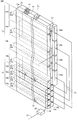
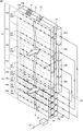
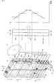
- FIG. 1 is a perspective view showing an outdoor heat exchanger according to Embodiment 1.
- FIG. it is sectional drawing which shows an example of the refrigerant path of a heat exchanger tube.
- FIG. 2 It is a perspective view which shows the outdoor heat exchanger which concerns on Embodiment 2.
- FIG. It is a figure which shows the flow of the refrigerant
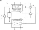
- the air conditioner 1 includes a compressor 3, an indoor heat exchanger 5, an indoor fan 7, an expansion device 9, an outdoor heat exchanger 11, an outdoor fan 21, a four-way valve 23, and a control unit 51. ing.
- the compressor 3, the indoor heat exchanger 5, the expansion device 9, the outdoor heat exchanger 11, and the four-way valve 23 are connected by refrigerant piping.
- the indoor heat exchanger 5 and the indoor fan 7 are arranged in the indoor unit 4.
- the outdoor heat exchanger 11 and the outdoor fan 21 are disposed in the outdoor unit 10.
- a series of operations of the air conditioner 1 are controlled by the control unit 51.
- the outdoor heat exchanger 11 includes a main heat exchange unit 13 (second heat exchange unit) and an auxiliary heat exchange unit 15 (first heat exchange unit).
- a main heat exchange unit 13 is disposed on the auxiliary heat exchange unit 15.
- the main heat exchange unit 13a is arranged in the first row
- the main heat exchange unit 13b is arranged in the second row.
- the auxiliary heat exchange unit 15a is arranged in the first row
- the auxiliary heat exchange unit 15b is arranged in the second row.
- a plurality of heat transfer tubes 32 (32a, 32b, 32c, 32d) (second refrigerant path) are arranged so as to penetrate the plurality of plate-like fins 31.
- a plurality of heat transfer tubes 33 (33a, 33b, 33c, 33d) (first refrigerant path) are arranged so as to penetrate the plurality of plate-like fins 31.
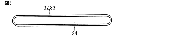
- heat transfer tubes 32 and 33 for example, flat tubes having a flat cross-sectional shape having a major axis and a minor axis are used.
- FIG. 3 shows a flat tube in which one refrigerant passage 34 is formed.
- FIG. 4 shows a flat tube in which a plurality of refrigerant passages 34 are formed.
- the heat transfer tubes 32 and 33 are not limited to flat tubes, and may be heat transfer tubes having a circular or oval cross-sectional shape, for example.
- a refrigerant path is formed by the heat transfer tubes 32 and 33.
- a refrigerant path group 14a, a refrigerant path group 14b, a refrigerant path group 14c, and a refrigerant path group 14d are formed.
- a plurality of refrigerant paths including one refrigerant path formed by the heat transfer tubes 32a are formed.
- a plurality of refrigerant paths including one refrigerant path formed by the heat transfer tubes 32b are formed.
- refrigerant path group 14c a plurality of refrigerant paths including one refrigerant path formed by the heat transfer tubes 32c are formed.
- refrigerant path group 14d a plurality of refrigerant paths including one refrigerant path formed by the heat transfer tube 32d are formed.
- a refrigerant path 16 a, a refrigerant path 16 b, a refrigerant path 16 c, and a refrigerant path 16 d are formed by the heat transfer tube 33.
- the refrigerant path 16a is formed by a heat transfer tube 33a.
- the refrigerant path 16b is formed by the heat transfer tube 33b.
- the refrigerant path 16c is formed by a heat transfer tube 33c.
- the refrigerant path 16d is formed by a heat transfer tube 33d.
- One end side of the refrigerant path groups 14a to 14d of the main heat exchange unit 13 and one end side of the refrigerant paths 16a to 16d of the auxiliary heat exchange unit 15 are connected by a connection pipe 35 via distributors 29a to 29d. More specifically, the refrigerant path 16a and the refrigerant path group 14a are connected. The refrigerant path 16b and the refrigerant path group 14d are connected. The refrigerant path 16c and the refrigerant path group 14c are connected. The refrigerant path 16d (first path) and the refrigerant path group 14b (second path) are connected.
- the other end side of the refrigerant path groups 14 a to 14 d of the main heat exchange unit is connected to the header 27.
- the other ends of the refrigerant paths 16a to 16d of the auxiliary heat exchange unit 15 are connected to the distributor 25 by connection pipes 36.
- the outdoor heat exchanger 11 is configured as described above.
- a high-temperature and high-pressure gaseous refrigerant is discharged from the compressor 3.
- the refrigerant flows according to dotted arrows.
- the discharged high-temperature and high-pressure gas refrigerant (single phase) flows into the outdoor heat exchanger 11 of the outdoor unit 10 through the four-way valve 23.
- the outdoor heat exchanger 11 heat exchange is performed between the refrigerant that has flowed in and the outside air (air) as a fluid supplied by the outdoor fan 21.
- the high-temperature and high-pressure gas refrigerant condenses into a high-pressure liquid refrigerant (single phase).
- the high-pressure liquid refrigerant sent out from the outdoor heat exchanger 11 becomes a two-phase refrigerant of low-pressure gas refrigerant and liquid refrigerant by the expansion device 9.
- the refrigerant in the two-phase state flows into the indoor heat exchanger 5 of the indoor unit 4.
- the indoor heat exchanger 5 heat exchange is performed between the flowing refrigerant in the two-phase state and the air supplied by the indoor fan 7.
- the liquid refrigerant evaporates to become a low-pressure gas refrigerant (single phase). By this heat exchange, the room is cooled.
- the low-pressure gas refrigerant sent out from the indoor heat exchanger 5 flows into the compressor 3 via the four-way valve 23, is compressed to become a high-temperature and high-pressure gas refrigerant, and is discharged from the compressor 3 again. Thereafter, this cycle is repeated.
- the refrigerant flow in the outdoor heat exchanger 11 during the cooling operation will be described in detail.
- the refrigerant sent from the compressor flows through the main heat exchange unit 13 and then flows through the auxiliary heat exchange unit 15.
- the air sent by the outdoor fan 21 to the main heat exchange unit 13 and the auxiliary heat exchange unit 15 is second from the main heat exchange unit 13a and the auxiliary heat exchange unit 15a in the first row (windward side). It flows toward the main heat exchanger 13b and the auxiliary heat exchanger 15b in the row (leeward row) (see thick arrows).
- the high-temperature and high-pressure gas refrigerant sent from the compressor 3 first flows into the header 27.
- the refrigerant that has flowed into the header 27 flows through the refrigerant path groups 14a to 14d of the main heat exchange unit 13 in the direction indicated by the arrows.
- the refrigerant that has flowed through the refrigerant path group 14a flows into the distributor 29a.
- the refrigerant that has flowed through the refrigerant path group 14b flows into the distributor 29b.
- the refrigerant that has flowed through the refrigerant path group 14c flows into the distributor 29c.
- the refrigerant that has flowed through the refrigerant path group 14d flows into the distributor 29d.
- the refrigerant that has flowed into each of the distributors 29a to 29d joins in each of the distributors 29a to 29d.
- the merged refrigerant flows from each of the distributors 29a to 29d into the auxiliary heat exchange unit 15 via the connection pipe 35.
- the refrigerant that has flowed into the auxiliary heat exchange unit 15 flows in the direction indicated by the arrows through the refrigerant paths 16a to 16d.
- the refrigerant sent from the distributor 29a flows through the refrigerant path 16a.
- the refrigerant sent from the distributor 29b flows through the refrigerant path 16d.
- the refrigerant sent from the distributor 29c flows through the refrigerant path 16c.
- the refrigerant sent from the distributor 29d flows through the refrigerant path 16b.
- the refrigerant that has flowed through each of the refrigerant paths 16a to 16d flows into the distributor 25 through the connection pipe 36.
- the refrigerants that have flowed together join, flow through the connection pipe 37, and are sent out of the outdoor heat exchanger 11.
- the refrigerant flows into the outdoor heat exchanger 11 as a gas refrigerant (single phase) with a degree of superheat.
- the refrigerant exchanges heat with the outside air (air) under a two-phase state of a liquid refrigerant and a gas refrigerant that have good heat transfer characteristics.
- the heat-exchanged refrigerant becomes a liquid refrigerant (single phase) having a degree of supercooling and is sent out from the outdoor heat exchanger 11.
- Liquid refrigerant single phase
- two-phase refrigerant has a smaller heat transfer coefficient and pressure loss in the heat transfer tube than two-phase refrigerant.
- the degree of supercooling of the refrigerant increases in the heat transfer tube, the temperature difference between the temperature of the refrigerant and the temperature outside the heat transfer tube is reduced. For this reason, the performance as an outdoor heat exchanger will fall significantly.
- the number of refrigerant paths 16a to 16d of the auxiliary heat exchanger 15 is less than the number of refrigerant paths 14a to 14d of the main heat exchanger 13. .
- coolant in the heat exchanger tube 33 in the auxiliary heat exchange part 15 can be raised, and the heat transfer rate in the heat exchanger tube 33 can be improved.
- a liquid refrigerant (single phase) flows as a refrigerant in the heat transfer tube 33 in the auxiliary heat exchange unit 15.
- the pressure loss in the heat exchanger tube 33 is also small, and the performance of the outdoor heat exchanger can be improved without adversely affecting the performance of the outdoor heat exchanger 11.
- the flow rate of the refrigerant per refrigerant path is reduced in order not to increase the pressure loss in the heat transfer tube.
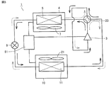
- a high-temperature and high-pressure gaseous refrigerant is discharged from the compressor 3.
- the refrigerant flows according to solid arrows.
- the discharged high-temperature and high-pressure gas refrigerant (single phase) flows into the indoor heat exchanger 5 through the four-way valve 23.
- the indoor heat exchanger 5 heat exchange is performed between the flowing gas refrigerant and the air supplied by the indoor fan 7, and the high-temperature and high-pressure gas refrigerant is condensed to a high-pressure liquid refrigerant (single phase). become.
- the high-pressure liquid refrigerant sent out from the indoor heat exchanger 5 becomes a two-phase refrigerant consisting of a low-pressure gas refrigerant and a liquid refrigerant by the expansion device 9.
- the refrigerant in the two-phase state flows into the outdoor heat exchanger 11.
- the outdoor heat exchanger 11 heat exchange is performed between the flowing two-phase refrigerant and the outside air (air) as a fluid supplied by the outdoor fan 21, and the two-phase refrigerant is a liquid refrigerant.
- the low-pressure gas refrigerant sent out from the outdoor heat exchanger 11 flows into the compressor 3 through the four-way valve 23, is compressed to become a high-temperature and high-pressure gas refrigerant, and is discharged from the compressor 3 again. Thereafter, this cycle is repeated.
- the sent refrigerant flows through the auxiliary heat exchange unit 15, and then flows through the main heat exchange unit 13.
- the air sent by the outdoor fan 21 to the main heat exchange unit 13 and the auxiliary heat exchange unit 15 is second from the main heat exchange unit 13a and the auxiliary heat exchange unit 15a in the first row (windward side). It flows toward the main heat exchanger 13b and the auxiliary heat exchanger 15b in the row (leeward row) (see thick arrows).
- the two-phase refrigerant sent from the indoor heat exchanger 5 via the expansion device 9 first flows into the distributor 25.
- the refrigerant that has flowed into the distributor 25 flows in the direction indicated by the arrow through the refrigerant paths 16a to 16d of the auxiliary heat exchange unit 15.
- the refrigerant that has flowed through the refrigerant path 16a flows into the distributor 29a through the connection pipe 35.
- the refrigerant that has flowed through the refrigerant path 16b flows into the distributor 29d through the connection pipe 35.
- the refrigerant that has flowed through the refrigerant path 16 c flows into the distributor 29 c through the connection pipe 35.
- the refrigerant that has flowed through the refrigerant path 16d flows into the distributor 29b through the connection pipe 35.
- the refrigerant flowing into each of the distributors 29a to 29d flows in the direction indicated by the arrow through the refrigerant path groups 14a to 14d of the main heat exchange unit 13.
- the refrigerant that has flowed into the distributor 29a flows through the refrigerant path group 14a.
- the refrigerant that has flowed into the distributor 29b flows through the refrigerant path group 14b.
- the refrigerant that has flowed into the distributor 29c flows through the refrigerant path group 14c.
- the refrigerant that has flowed into the distributor 29d flows through the refrigerant path group 14d.
- the refrigerant that has flowed through the refrigerant path groups 14 a to 14 d flows into the header 27.
- the refrigerant flowing into the header 27 is sent out of the outdoor heat exchanger 11.
- the refrigerant that has flowed through the outdoor heat exchanger 11 is sent to the compressor 3.
- the refrigerant sent out from the outdoor heat exchanger 11 is a gas refrigerant (single phase).
- heat exchange is performed between the outside air sent into the outdoor unit 10 by the outdoor fan 21 and the refrigerant sent into the outdoor heat exchanger 11.
- moisture in the outside air air
- water droplets grow on the surface of the outdoor heat exchanger 11.
- the grown water droplets flow downward through the drainage path of the outdoor heat exchanger 11 constituted by the fins 31 and the heat transfer tubes 32 and 33, and are discharged as drain water.
- the defrosting operation for removing frost is performed when the outside air becomes a certain temperature (for example, 0 ° C. (freezing point)) or lower.
- the defrosting operation is an operation in which high-temperature high-pressure gas refrigerant (hot gas) is sent from the compressor 3 to the outdoor heat exchanger 11 in order to prevent frost from adhering to the outdoor heat exchanger 11 that functions as an evaporator. That is.
- the defrosting operation may be performed when the duration time of the heating operation reaches a predetermined value (for example, 30 minutes). In addition, the defrosting operation may be performed before the heating operation when the temperature of the outside air is a certain temperature (for example, minus 6 ° C.) or less.
- the frost (and ice) adhering to the outdoor heat exchanger 11 is melted by the high-temperature and high-pressure refrigerant sent to the outdoor heat exchanger 11.
- the high-temperature and high-pressure gas refrigerant discharged from the compressor 3 can be sent to the outdoor heat exchanger 11 through the four-way valve 23.
- a bypass refrigerant pipe (not shown) may be provided between the compressor 3 and the outdoor heat exchanger 11.
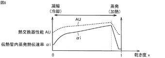
- FIG. 8 shows a relationship A graph (solid line graph) and a relationship B graph (dotted line graph), respectively.
- the AU value is expressed by the following equation.
- AU value 1 / (Ro + Ri + Rd)
- the AU value increases and the heat exchange performance improves. For example, in order to reduce the heat resistance Ro outside the heat transfer tube, the heat transfer area outside the heat transfer tube is increased, the flow velocity of the fluid outside the heat transfer tube is increased, or the heat transfer coefficient outside the heat transfer tube is improved. It is necessary to have a mechanism. In order to reduce the heat resistance Ri in the heat transfer tube, it is necessary to increase the evaporation heat transfer rate ⁇ i in the heat transfer tube or increase the heat transfer area in the heat transfer tube.
- liquid refrigerant and gas refrigerant are mixed in the heat transfer tubes 32 and 33 of the outdoor heat exchanger 11 into which the two-phase refrigerant flows.
- the liquid refrigerant exists as a thin liquid film attached to the inner wall surfaces of the heat transfer tubes 32 and 33. For this reason, when the two-phase refrigerant in the heat transfer tubes 32 and 33 evaporates, the evaporation heat transfer coefficient in the heat transfer tubes is higher than in the case of a single-phase refrigerant (liquid refrigerant or gas refrigerant), and The exchange performance AU value is also high.
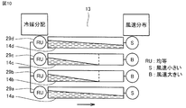
- the outdoor unit 10 which accommodated the outdoor heat exchanger 11 is a horizontal blowing outdoor unit
- an outdoor fan 21 is disposed so as to face the outdoor heat exchanger 11.
- outside air is sent into the outdoor unit from one side surface portion of the outdoor unit (not shown).
- the sent outside air passes through the outdoor heat exchanger 11 and is then sent out of the outdoor unit from the other side surface portion of the outdoor unit.
- the wind speed of the outside air passing through the outdoor heat exchanger 11 is distributed depending on the positional relationship with the outdoor fan 21.
- the portion of the outdoor heat exchanger 11 that is closer to the outdoor fan 21 has a higher wind speed of the outside air that passes through the portion of the outdoor heat exchanger 11.
- the portion of the outdoor heat exchanger 11 that is located away from the outdoor fan 21 has a lower wind speed of the outside air passing through the portion of the outdoor heat exchanger 11.
- the wind speed of the outdoor air that passes through the portion of the outdoor heat exchanger 11 that faces the outdoor fan 21 is the amount of outside air that passes through the portion of the outdoor heat exchanger 11 that does not face the outdoor fan 21. It becomes larger than the wind speed. That is, in the outdoor heat exchanger 11, the wind speed of the outside air passing through the portion located inside the projection surface (the region indicated by the two-dot chain line) of the outdoor fan 21 is higher than the wind speed of the outside air passing through the portion located outside the projection surface. large.
- the proportion of each part of the outdoor heat exchanger 11 contributing to heat exchange with respect to the total heat exchange amount varies depending on the part of the outdoor heat exchanger 11.
- the ratio contributing to the heat exchange is relatively high in the portion of the outdoor heat exchanger 11 that is close to the outdoor fan 21, and relatively in the portion of the outdoor heat exchanger 11 that is located away from the outdoor fan 21. Lower.
- the wind speed (average value) of the outside air passing through the refrigerant path group 14b is larger than the wind speed (average value) of the outside air passing through the refrigerant path group 14d.
- the ratio that the refrigerant path group 14b contributes to the heat exchange is higher than the ratio that the refrigerant path group 14d contributes to the heat exchange.
- the heat exchange amount in each refrigerant path (group) varies depending on the wind speed distribution.
- the refrigerant flowing through the refrigerant path groups 14a to 14d and the heat exchange performance between the refrigerant and the outside air will be described.
- a case will be described in which a two-phase refrigerant of a liquid refrigerant and a gas refrigerant flows evenly into each of the distributors 29a to 29d.
- the refrigerant (liquid refrigerant) that has evenly flowed into the distributors 29a to 29d exchanges heat with the outside air while flowing through the refrigerant path groups 14a to 14d. Done to become a gas refrigerant.
- the refrigerant becomes a gas refrigerant (single phase) and is sent out from the main heat exchanging section 13. Therefore, the liquid refrigerant flowing through the refrigerant path groups 14b and 14c having a relatively high wind speed is the refrigerant path. Evaporation is completed in the middle of the groups 14b and 14c, and becomes a gas refrigerant.
- the refrigerant distribution is adjusted according to the wind speed distribution.
- the main heat exchanging unit 13 and the auxiliary heat exchanging unit 15 are arranged so that the refrigerant containing a larger amount of liquid refrigerant flows into the refrigerant path groups 14b and 14c having a relatively high wind speed. Yes.
- the refrigerant flowing into the auxiliary heat exchanging section 15 is distributed in the distributor 25 and then sequentially flows through the refrigerant paths 16a to 16d, the distributors 29a to 29d, the refrigerant path groups 14a to 14 and the header 27.
- the refrigerant paths 16a to 16d of the auxiliary heat exchange section 15 when the refrigerant friction pressure loss varies, the flow rate ratio of the refrigerant flowing through the refrigerant paths 16a to 16d and the refrigerant path groups 14a to 14 changes. .
- the dryness refers to the ratio (ratio) of the mass of the gas refrigerant to the mass of wet steam (liquid refrigerant + gas refrigerant).
- FIG. 12 shows the graph. The horizontal axis is the dryness, and the vertical axis is the pressure loss in the heat transfer tube.
- the refrigerant flowing into the outdoor heat exchanger 11 functioning as an evaporator is a two-phase refrigerant consisting of a liquid refrigerant and a gas refrigerant
- the temperature becomes a saturation temperature according to the pressure.
- the saturation temperature also decreases.
- the refrigerant flows from the auxiliary heat exchange unit 15 to the main heat exchange unit 13.
- the refrigerant paths 16a to 16d of the auxiliary heat exchange section 15 have a smaller number of paths than the refrigerant path groups 14a to 14d of the main heat exchange section 13.
- the flow rate of the refrigerant flowing through the refrigerant paths 16a to 16d increases, and the friction pressure loss of the refrigerant also increases.
- the auxiliary heat exchange unit 15 is disposed below the main heat exchange unit 13 so as to be in contact with the main heat exchange unit 13.
- the refrigerant path 16 d is disposed at a position closest to the main heat exchange unit 13. For this reason, since heat is conducted from the refrigerant path 16d through which the refrigerant A flows to the main heat exchanging unit 13, the refrigerant in the two-phase state is cooled and condensed in the refrigerant path 16d, so that the dryness of the refrigerant becomes low. By reducing the dryness of the refrigerant, the friction pressure loss of the refrigerant is also reduced.
- the flow rate of the refrigerant (liquid refrigerant) flowing through the refrigerant path 16d is larger than the flow rate of the refrigerant (liquid refrigerant) flowing through the other refrigerant paths.
- the refrigerant path 16d (first path) through which more liquid refrigerant flows is connected to the refrigerant path group 14b (second path) where the wind speed of the outside air passing therethrough is relatively high.
- the refrigerant containing more liquid refrigerant is efficiently heat-exchanged and evaporated to become a gas refrigerant.
- the performance of the outdoor heat exchanger 11 can be improved.
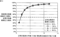
- FIG. 13 shows the relationship between the ratio of the refrigerant friction pressure loss between the auxiliary heat exchange unit 15 and the main heat exchange unit 13 and the ratio of the number of refrigerant paths between the auxiliary heat exchange unit and the main heat exchange unit.
- the refrigerant was assumed to be R32.
- the number of heat transfer tubes per refrigerant path was the same.
- the pressure between the main heat exchange unit 13 and the auxiliary heat exchange unit 15 was 0.80 MPa (saturation temperature ⁇ 0.5 ° C.).
- the friction pressure loss of the main heat exchange part was calculated as a parameter.
- the refrigerant flows from the main heat exchange unit 13 to the auxiliary heat exchange unit 15.
- the refrigerant flowing through the main heat exchange unit 13 is dissipated to melt frost attached to the main heat exchange unit 13. For this reason, when flowing through the auxiliary heat exchanging unit 15, the refrigerant is sufficiently condensed to be a liquid refrigerant.
- the refrigerant flowing through the refrigerant path 16d does not cause a phase change.
- the frictional pressure loss of the refrigerant hardly fluctuates. For this reason, the heat exchange between the refrigerant and the outside air when operating as an evaporator (heating operation) can be improved without affecting the distribution of the refrigerant when performing the defrosting operation.
- the following method is employed so that frost is not left. can do.
- the flow path cross-sectional area of the heat transfer tube of the refrigerant path 16d is narrowed.
- the diameter of the connection pipe connecting the refrigerant path 16d and the distributor is reduced.
- the pressure resistance of the refrigerant path 16d also increases, and while maintaining the constant flow ratio of the refrigerant in the refrigerant paths 16a to 16d of the auxiliary heat exchanger 15 when operating the outdoor heat exchanger 11 as an evaporator,
- coolants can be flowed through the refrigerant
- the outdoor heat exchanger 11 includes a main heat exchange unit 13 (second heat exchange unit) and an auxiliary heat exchange unit 15 (first heat exchange unit).
- main heat exchange unit 13 refrigerant path groups 14a, 14b, 14c, and 14d (second refrigerant paths) are formed.
- auxiliary heat exchanger 15 refrigerant paths 16a, 16b, 16c, and 16d (first refrigerant path) are formed.
- the connection mode between the refrigerant path groups 14a, 14b, 14c, and 14d and the refrigerant paths 16a, 16b, 16c, and 16d is the outdoor heat exchanger 11 according to the first embodiment.
- the connection mode is different.
- the refrigerant path 16a first path
- the refrigerant path group 14b in which the wind speed of the outside air passing through is relatively large. (Second path) is connected.
- the refrigerant path 16b and the refrigerant path group 14a are connected.
- the refrigerant path 16c and the refrigerant path group 14d are connected.
- the refrigerant path 16d and the refrigerant path group 14c are connected.
- the operation of the air conditioner 1 is basically the same as the operation of the air conditioner 1 according to Embodiment 1.
- the refrigerant discharged from the compressor 3 sequentially flows through the four-way valve 23, the outdoor heat exchanger 11, the expansion device 9, and the indoor heat exchanger 5 and returns to the compressor 3 (see the dotted arrows in FIG. 5). ).
- the outdoor heat exchanger 11 heat exchange is performed between the high-temperature and high-pressure gas refrigerant and the outside air.
- the high-temperature and high-pressure gas refrigerant condenses into a high-pressure liquid refrigerant (single phase).
- the high-pressure liquid refrigerant becomes a two-phase refrigerant consisting of a low-pressure gas refrigerant and a liquid refrigerant.
- the indoor heat exchanger 5 heat exchange is performed between the refrigerant in the two-phase state and the outside air.
- the liquid refrigerant evaporates into a low-pressure gas refrigerant (single phase). This heat exchange cools the room. Thereafter, this cycle is repeated.
- the refrigerant discharged from the compressor 3 sequentially flows through the four-way valve 23, the indoor heat exchanger 5, the expansion device 9, and the outdoor heat exchanger 11 and returns to the compressor 3 (solid arrow in FIG. 5). reference).
- the indoor heat exchanger 5 heat exchange is performed between the high-temperature and high-pressure gas refrigerant and the outside air.
- the high-temperature and high-pressure gas refrigerant condenses into a high-pressure liquid refrigerant (single phase). This heat exchange heats the room.
- the high-pressure liquid refrigerant becomes a two-phase refrigerant consisting of a low-pressure gas refrigerant and a liquid refrigerant.
- the outdoor heat exchanger 11 heat exchange is performed between the two-phase refrigerant and the outside air.
- the liquid refrigerant evaporates into a low-pressure gas refrigerant (single phase). Thereafter, this cycle is repeated.
- the two-phase refrigerant sent from the indoor heat exchanger 5 via the expansion device 9 first flows into the distributor 25.
- the refrigerant that has flowed into the distributor 25 flows in the direction indicated by the arrow through the refrigerant paths 16a to 16d of the auxiliary heat exchange unit 15.
- the refrigerant that has flowed through the refrigerant path 16a flows into the distributor 29b through the connection pipe 35.
- the refrigerant that has flowed through the refrigerant path 16b flows into the distributor 29a through the connection pipe 35.
- the refrigerant that has flowed through the refrigerant path 16 c flows into the distributor 29 d through the connection pipe 35.
- the refrigerant that has flowed through the refrigerant path 16d flows into the distributor 29c through the connection pipe 35.
- the refrigerant flowing into each of the distributors 29a to 29d flows in the direction indicated by the arrow through the refrigerant path groups 14a to 14d of the main heat exchange unit 13.
- the refrigerant that has flowed into the distributor 29a flows through the refrigerant path group 14a.
- the refrigerant that has flowed into the distributor 29b flows through the refrigerant path group 14b.
- the refrigerant that has flowed into the distributor 29c flows through the refrigerant path group 14c.
- the refrigerant that has flowed into the distributor 29d flows through the refrigerant path group 14d.
- the refrigerant that has flowed through the refrigerant path groups 14 a to 14 d flows into the header 27.
- the refrigerant flowing into the header 27 is sent out of the outdoor heat exchanger 11.
- heat exchange is performed between the outside air sent into the outdoor unit 10 by the outdoor fan 21 and the refrigerant sent into the outdoor heat exchanger 11.
- moisture in the outside air air
- water droplets grow on the surface of the outdoor heat exchanger 11.
- the grown water droplets flow downward through the drainage path of the outdoor heat exchanger 11 constituted by the fins 31 and the heat transfer tubes 32 and 33, and are discharged as drain water.
- the drain water is discharged mainly from the gravity toward the lower part of the outdoor heat exchanger 11, the amount of water is relatively large in the lower part of the outdoor heat exchanger 11.
- measures are taken to prevent the outdoor heat exchanger 11 from being damaged by corrosion of the fins 31 or the heat transfer tubes 33. That is, the lower part of the outdoor heat exchanger 11 is often only in contact with the casing of the outdoor unit or in contact with an insulator.
- drain water tends to stay in the lower part of the outdoor heat exchanger 11.
- the drain water is more likely to stay than the other refrigerant paths 16b to 16d.
- the surface tension of the lower surface of the heat transfer tube is larger than that of a circular heat transfer tube having a general cross-sectional shape. For this reason, water droplets are likely to stay at the lowermost stage of the auxiliary heat exchange unit 15.
- Drain water is low-temperature water generated by condensation of moisture contained in the outside air. Since the low-temperature drain water is likely to stay in the refrigerant path 16a, the two-phase refrigerant flowing through the refrigerant path 16a is cooled, and the gas refrigerant is condensed. Condensation of the gas refrigerant reduces the dryness of the refrigerant, and the refrigerant flowing through the refrigerant path 16a reduces the friction pressure loss in the heat transfer tube 33a (see FIG. 12).
- the flow rate of the refrigerant (liquid refrigerant) flowing through the refrigerant path 16a is increased, and the flow rate of the refrigerant flowing through the refrigerant path 16a is larger than the flow rate of the refrigerant flowing through the other refrigerant paths 16b to 16d.
- the refrigerant path 16 a of the auxiliary heat exchange unit 15 and the refrigerant path group 14 b of the main heat exchange unit 13 are connected by a connection pipe 35.
- the wind speed of the outside air passing through is relatively high.
- the refrigerant containing more liquid refrigerant is efficiently heat-exchanged and evaporated to become a gas refrigerant.
- the performance of the outdoor heat exchanger 11 can be improved.
- the flow path shape inside the distributor 25 or the distributors 29a to 29d may be changed. Further, the dimensions of the connection pipe 36 that connects the distributor 25 and the refrigerant paths 16a to 16d may be adjusted. Furthermore, the dimensions of the connecting pipes connecting the distributors 29a to 29d and the refrigerant path groups 16a to 16d may be adjusted.
- the refrigerant flowing through the main heat exchange unit 13 is dissipated to melt the frost attached to the main heat exchange unit 13, so that the auxiliary When flowing through the heat exchanging section 15, the refrigerant is sufficiently condensed to be a liquid refrigerant.
- the drain water generated during the defrosting operation does not cause a phase change in the refrigerant flowing through the refrigerant paths 16a to 16d.
- the frictional pressure loss of the refrigerant hardly fluctuates. For this reason, the heat exchange between the refrigerant and the outside air when operating as an evaporator (heating operation) can be improved without affecting the distribution of the refrigerant when performing the defrosting operation.
- the refrigerant path 16a When the refrigerant path 16a is not connected to the refrigerant path group 14a disposed at a position closest to the auxiliary heat exchanging section 15 in the main heat exchanging section 13, no frost is left by taking the following method. can do.
- the flow path cross-sectional area of the heat transfer tube of the refrigerant path 16a is narrowed.
- the diameter of the connection pipe connecting the refrigerant path 16a and the distributor is reduced.
- the pressure resistance of the refrigerant path 16a also increases, and when the defrosting operation is performed while keeping the refrigerant diversion ratio of the refrigerant path of the auxiliary heat exchanging section when operating as an evaporator, the refrigerant path
- the diversion ratio of the refrigerant path other than 16a can be increased.
- coolants can be flowed through the refrigerant
- any refrigerant such as the refrigerant R410A, the refrigerant R407C, the refrigerant R32, the refrigerant R507A, the refrigerant HFO1234yf, and the like can be used for distribution during defrosting. It is possible to improve the performance of the heat exchanger when operating as an evaporator without affecting it.
- refrigerating machine oil used for the air conditioner 1 a refrigerating machine oil having compatibility in consideration of mutual solubility with the applied refrigerant is used.
- fluorocarbon refrigerants such as refrigerant R410A use alkylbenzene oil-based, ester oil-based or ether oil-based refrigerator oil.
- refrigerating machine oil such as mineral oil or fluorine oil may be used.
- the present invention is effectively used for an air conditioner having an outdoor heat exchanger provided with a main heat exchange part and an auxiliary heat exchange part.
Abstract
Description
はじめに、冷凍サイクル装置としての空気調和装置の全体の構成(冷媒回路)について説明する。図1に示すように、空気調和装置1は、圧縮機3、室内熱交換器5、室内ファン7、絞り装置9、室外熱交換器11、室外ファン21、四方弁23および制御部51を備えている。圧縮機3、室内熱交換器5、絞り装置9、室外熱交換器11および四方弁23が、冷媒配管によって繋がっている。
熱抵抗の値が小さくなることでAU値は高くなり、熱交換性能は向上する。たとえば、伝熱管外の熱抵抗Roを小さくするには、伝熱管外の伝熱面積を増加するか、伝熱管外の流体の流速を上げるか、または、伝熱管外の熱伝達率を向上させる機構を備えている必要がある。また、伝熱管内の熱抵抗Riを小さくするには、伝熱管内の蒸発熱伝達率αiを上げるか、または、伝熱管内の伝熱面積を大きくする必要がある。
実施の形態2に係る室外ユニットの室外熱交換器について説明する。図14に示すように、室外熱交換器11は、主熱交換部13(第2熱交換部)と補助熱交換部15(第1熱交換部)とを備えている。主熱交換部13では、冷媒パス群14a、14b、14c、14d(第2冷媒パス)が形成されている。補助熱交換部15では、冷媒パス16a、16b、16c、16d(第1冷媒パス)が形成されている。
Claims (10)
- 室外熱交換器を備えた室外ユニットであって、
前記室外熱交換器は、
第1熱交換部と、
前記第1熱交換部と接触するように配置された第2熱交換部と
を含み、
前記第1熱交換部は、複数の第1冷媒パスを有し、
前記第2熱交換部は、複数の第2冷媒パスを有し、
前記複数の第1冷媒パスのうち、前記第2熱交換部に最も近い位置に配置された第1パスと、前記複数の第2冷媒パスのうち、前記第2熱交換部を通り抜ける流体の流速が相対的に大きい領域に配置された第2パスとが、接続された、室外ユニット。 - 前記複数の第1冷媒パスの数は、前記複数の第2冷媒パスの数よりも少ない、請求項1記載の室外ユニット。
- 前記室外熱交換器と対向するように配置され、前記室外熱交換器へ前記流体を送り込む送風部を備え、
前記送風部から前記室外熱交換器を見て、前記第2パスは、前記送風部と前記第2熱交換部とが平面視的に重なる領域に位置するように配置された、請求項1記載の室外ユニット。 - 前記複数の第1冷媒パスのそれぞれおよび前記複数の第2冷媒パスのそれぞれは、伝熱管を含み、
前記伝熱管の断面形状は扁平型である、請求項1記載の室外ユニット。 - 室外熱交換器を備えた室外ユニットであって、
前記室外熱交換器は、
第1熱交換部と、
前記第1熱交換部と接触するように配置された第2熱交換部と
を含み、
前記第1熱交換部は、複数の第1冷媒パスを有し、
前記第2熱交換部は、複数の第2冷媒パスを有し、
前記複数の第1冷媒パスのうち、前記第2熱交換部から最も離れた位置に配置された第1パスと、前記複数の第2冷媒パスのうち、前記第2熱交換部を通り抜ける流体の流速が相対的に大きい領域に配置された第2パスとが、接続された、室外ユニット。 - 前記第1熱交換部は、前記第2熱交換部の下方に配置され、
前記第1パスは、前記第1熱交換部における最下段に配置された、請求項5記載の室外ユニット。 - 前記複数の第1冷媒パスの数は、前記複数の第2冷媒パスの数よりも少ない、請求項5記載の室外ユニット。
- 前記室外熱交換器と対向するように配置され、前記室外熱交換器へ前記流体を送り込む送風部を備え、
前記送風部から前記室外熱交換器を見て、前記第2パスは、前記送風部と前記第2熱交換部とが平面視的に重なる領域に位置するように配置された、請求項5記載の室外ユニット。 - 前記複数の第1冷媒パスのそれぞれおよび前記複数の第2冷媒パスのそれぞれは、伝熱管を含み、
前記伝熱管の断面形状は扁平型である、請求項5記載の室外ユニット。 - 請求項1~9のいずれか1項に記載の室外ユニットを備えた冷凍サイクル装置であって、
前記室外熱交換器が蒸発器として動作する状態では、前記第1熱交換部から前記第2熱交換部へ冷媒が流れる、冷凍サイクル装置。
Priority Applications (9)
| Application Number | Priority Date | Filing Date | Title |
|---|---|---|---|
| ES20201281T ES2960725T3 (es) | 2016-05-19 | 2016-05-19 | Unidad exterior y aparato de ciclo de refrigeración que incluye la misma |
| CN201680085102.5A CN109073290B (zh) | 2016-05-19 | 2016-05-19 | 室外单元及具备该室外单元的制冷循环装置 |
| US16/083,553 US10914499B2 (en) | 2016-05-19 | 2016-05-19 | Outdoor unit and refrigeration cycle apparatus including the same |
| EP16902412.2A EP3460358A4 (en) | 2016-05-19 | 2016-05-19 | EXTERNAL UNIT AND REFRIGERATION CYCLE DEVICE COMPRISING THE SAME |
| SG11201807906YA SG11201807906YA (en) | 2016-05-19 | 2016-05-19 | Outdoor unit and refrigeration cycle apparatus including the same |
| PCT/JP2016/064866 WO2017199393A1 (ja) | 2016-05-19 | 2016-05-19 | 室外ユニットおよびそれを備えた冷凍サイクル装置 |
| JP2018518018A JP6727297B2 (ja) | 2016-05-19 | 2016-05-19 | 室外ユニットおよびそれを備えた冷凍サイクル装置 |
| AU2016406843A AU2016406843B2 (en) | 2016-05-19 | 2016-05-19 | Outdoor Unit and Refrigeration Cycle Apparatus Including the Same |
| EP20201281.1A EP3783280B1 (en) | 2016-05-19 | 2016-05-19 | Outdoor unit and refrigeration cycle apparatus including the same |
Applications Claiming Priority (1)
| Application Number | Priority Date | Filing Date | Title |
|---|---|---|---|
| PCT/JP2016/064866 WO2017199393A1 (ja) | 2016-05-19 | 2016-05-19 | 室外ユニットおよびそれを備えた冷凍サイクル装置 |
Publications (1)
| Publication Number | Publication Date |
|---|---|
| WO2017199393A1 true WO2017199393A1 (ja) | 2017-11-23 |
Family
ID=60326291
Family Applications (1)
| Application Number | Title | Priority Date | Filing Date |
|---|---|---|---|
| PCT/JP2016/064866 WO2017199393A1 (ja) | 2016-05-19 | 2016-05-19 | 室外ユニットおよびそれを備えた冷凍サイクル装置 |
Country Status (8)
| Country | Link |
|---|---|
| US (1) | US10914499B2 (ja) |
| EP (2) | EP3460358A4 (ja) |
| JP (1) | JP6727297B2 (ja) |
| CN (1) | CN109073290B (ja) |
| AU (1) | AU2016406843B2 (ja) |
| ES (1) | ES2960725T3 (ja) |
| SG (1) | SG11201807906YA (ja) |
| WO (1) | WO2017199393A1 (ja) |
Cited By (3)
| Publication number | Priority date | Publication date | Assignee | Title |
|---|---|---|---|---|
| WO2019130394A1 (ja) * | 2017-12-25 | 2019-07-04 | 三菱電機株式会社 | 熱交換器および冷凍サイクル装置 |
| JPWO2019003385A1 (ja) * | 2017-06-29 | 2019-11-07 | 三菱電機株式会社 | 室外ユニットおよび冷凍サイクル装置 |
| JPWO2020194442A1 (ja) * | 2019-03-25 | 2021-10-21 | 三菱電機株式会社 | 熱交換器ユニット及び冷凍サイクル装置 |
Families Citing this family (1)
| Publication number | Priority date | Publication date | Assignee | Title |
|---|---|---|---|---|
| JP6529604B2 (ja) * | 2015-12-01 | 2019-06-12 | 三菱電機株式会社 | 冷凍サイクル装置 |
Citations (7)
| Publication number | Priority date | Publication date | Assignee | Title |
|---|---|---|---|---|
| JPH08219493A (ja) * | 1995-02-09 | 1996-08-30 | Daikin Ind Ltd | 空気調和機 |
| JP2010127570A (ja) * | 2008-11-28 | 2010-06-10 | Mitsubishi Electric Corp | ヒートポンプ給湯機及び冷凍機器 |
| JP2012163328A (ja) * | 2011-01-21 | 2012-08-30 | Daikin Industries Ltd | 熱交換器および空気調和機 |
| JP2013083419A (ja) | 2011-09-30 | 2013-05-09 | Daikin Industries Ltd | 熱交換器および空気調和機 |
| WO2013161799A1 (ja) * | 2012-04-26 | 2013-10-31 | 三菱電機株式会社 | 熱交換器及びこの熱交換器を備えた冷凍サイクル装置 |
| WO2015111220A1 (ja) * | 2014-01-27 | 2015-07-30 | 三菱電機株式会社 | 熱交換器、及び、空気調和装置 |
| WO2015132963A1 (ja) * | 2014-03-07 | 2015-09-11 | 三菱電機株式会社 | 熱交換器及び空気調和機 |
Family Cites Families (22)
| Publication number | Priority date | Publication date | Assignee | Title |
|---|---|---|---|---|
| JPS531351A (en) * | 1976-06-25 | 1978-01-09 | Matsushita Electric Ind Co Ltd | Room cooling and heating system |
| JP3324240B2 (ja) * | 1993-12-01 | 2002-09-17 | 株式会社デンソー | 冷媒凝縮器 |
| JP3216960B2 (ja) * | 1994-09-19 | 2001-10-09 | 株式会社日立製作所 | 空気調和機の室外機、室内機及びそれらに用いられる冷媒分配器 |
| JPH11304293A (ja) * | 1997-07-10 | 1999-11-05 | Denso Corp | 冷媒凝縮器 |
| JP4006821B2 (ja) * | 1998-04-22 | 2007-11-14 | 株式会社デンソー | 凝縮装置 |
| JP2000081255A (ja) * | 1998-09-07 | 2000-03-21 | Sanyo Electric Co Ltd | 熱交換器 |
| KR100505236B1 (ko) * | 2002-12-18 | 2005-08-03 | 엘지전자 주식회사 | 공기조화기 |
| JP2007147221A (ja) * | 2005-11-30 | 2007-06-14 | Matsushita Electric Ind Co Ltd | フィン付き熱交換器 |
| CN201335512Y (zh) * | 2008-08-22 | 2009-10-28 | Tcl集团股份有限公司 | 一种改进流程结构的冷凝器装置 |
| JP5385588B2 (ja) * | 2008-10-30 | 2014-01-08 | シャープ株式会社 | 空気調和機の室外機 |
| CN101545702A (zh) * | 2009-05-06 | 2009-09-30 | 海信(山东)空调有限公司 | 一种空调室外机冷凝器及采用该冷凝器的室外机 |
| CN201402010Y (zh) * | 2009-05-06 | 2010-02-10 | 海信(山东)空调有限公司 | 一种空调室外机冷凝器及采用该冷凝器的室外机 |
| WO2013046729A1 (ja) * | 2011-09-30 | 2013-04-04 | ダイキン工業株式会社 | 熱交換器および空気調和機 |
| JP5907752B2 (ja) * | 2012-02-20 | 2016-04-26 | 株式会社ケーヒン・サーマル・テクノロジー | 熱交換器 |
| EP2853843B1 (en) * | 2012-04-26 | 2020-03-11 | Mitsubishi Electric Corporation | A refrigerant distributing device, and heat exchanger equipped with such a refrigerant distributing device |
| CN102798203B (zh) * | 2012-08-29 | 2014-08-27 | 海信(山东)空调有限公司 | 空调室外机冷凝器及安装有该冷凝器的空调室外机 |
| JP5644889B2 (ja) * | 2013-04-30 | 2014-12-24 | ダイキン工業株式会社 | 空気調和機の室内ユニット |
| CN105283718B (zh) | 2013-06-13 | 2017-10-24 | 三菱电机株式会社 | 空调装置 |
| JP2015052439A (ja) * | 2013-09-09 | 2015-03-19 | ダイキン工業株式会社 | 熱交換器 |
| ES2700604T3 (es) | 2013-09-11 | 2019-02-18 | Daikin Ind Ltd | Intercambiador de calor y aparato de aire acondicionado |
| JP6171765B2 (ja) * | 2013-09-11 | 2017-08-02 | ダイキン工業株式会社 | 熱交換器 |
| JP6253814B2 (ja) * | 2015-01-30 | 2017-12-27 | 三菱電機株式会社 | 熱交換器、及び冷凍サイクル装置 |
-
2016
- 2016-05-19 SG SG11201807906YA patent/SG11201807906YA/en unknown
- 2016-05-19 CN CN201680085102.5A patent/CN109073290B/zh active Active
- 2016-05-19 JP JP2018518018A patent/JP6727297B2/ja active Active
- 2016-05-19 EP EP16902412.2A patent/EP3460358A4/en not_active Withdrawn
- 2016-05-19 US US16/083,553 patent/US10914499B2/en active Active
- 2016-05-19 AU AU2016406843A patent/AU2016406843B2/en active Active
- 2016-05-19 ES ES20201281T patent/ES2960725T3/es active Active
- 2016-05-19 EP EP20201281.1A patent/EP3783280B1/en active Active
- 2016-05-19 WO PCT/JP2016/064866 patent/WO2017199393A1/ja active Application Filing
Patent Citations (7)
| Publication number | Priority date | Publication date | Assignee | Title |
|---|---|---|---|---|
| JPH08219493A (ja) * | 1995-02-09 | 1996-08-30 | Daikin Ind Ltd | 空気調和機 |
| JP2010127570A (ja) * | 2008-11-28 | 2010-06-10 | Mitsubishi Electric Corp | ヒートポンプ給湯機及び冷凍機器 |
| JP2012163328A (ja) * | 2011-01-21 | 2012-08-30 | Daikin Industries Ltd | 熱交換器および空気調和機 |
| JP2013083419A (ja) | 2011-09-30 | 2013-05-09 | Daikin Industries Ltd | 熱交換器および空気調和機 |
| WO2013161799A1 (ja) * | 2012-04-26 | 2013-10-31 | 三菱電機株式会社 | 熱交換器及びこの熱交換器を備えた冷凍サイクル装置 |
| WO2015111220A1 (ja) * | 2014-01-27 | 2015-07-30 | 三菱電機株式会社 | 熱交換器、及び、空気調和装置 |
| WO2015132963A1 (ja) * | 2014-03-07 | 2015-09-11 | 三菱電機株式会社 | 熱交換器及び空気調和機 |
Cited By (5)
| Publication number | Priority date | Publication date | Assignee | Title |
|---|---|---|---|---|
| JPWO2019003385A1 (ja) * | 2017-06-29 | 2019-11-07 | 三菱電機株式会社 | 室外ユニットおよび冷凍サイクル装置 |
| WO2019130394A1 (ja) * | 2017-12-25 | 2019-07-04 | 三菱電機株式会社 | 熱交換器および冷凍サイクル装置 |
| EP3734190A4 (en) * | 2017-12-25 | 2021-01-06 | Mitsubishi Electric Corporation | HEAT EXCHANGER AND COOLING CYCLE DEVICE |
| JPWO2020194442A1 (ja) * | 2019-03-25 | 2021-10-21 | 三菱電機株式会社 | 熱交換器ユニット及び冷凍サイクル装置 |
| JP7080395B2 (ja) | 2019-03-25 | 2022-06-03 | 三菱電機株式会社 | 熱交換器ユニット及び冷凍サイクル装置 |
Also Published As
| Publication number | Publication date |
|---|---|
| JP6727297B2 (ja) | 2020-07-22 |
| SG11201807906YA (en) | 2018-12-28 |
| US20190078817A1 (en) | 2019-03-14 |
| EP3460358A1 (en) | 2019-03-27 |
| US10914499B2 (en) | 2021-02-09 |
| AU2016406843A1 (en) | 2018-10-11 |
| CN109073290A (zh) | 2018-12-21 |
| EP3460358A4 (en) | 2019-05-15 |
| AU2016406843B2 (en) | 2019-09-12 |
| JPWO2017199393A1 (ja) | 2019-01-24 |
| ES2960725T3 (es) | 2024-03-06 |
| EP3783280A1 (en) | 2021-02-24 |
| CN109073290B (zh) | 2020-10-30 |
| EP3783280B1 (en) | 2023-09-20 |
Similar Documents
| Publication | Publication Date | Title |
|---|---|---|
| US10386081B2 (en) | Air-conditioning device | |
| CN109312971B (zh) | 制冷循环装置 | |
| WO2018047416A1 (ja) | 空気調和装置 | |
| JP4922669B2 (ja) | 空気調和機及び空気調和機の熱交換器 | |
| WO2013051166A1 (ja) | 冷凍サイクル装置 | |
| JP6157723B2 (ja) | 空気調和装置 | |
| WO2017199393A1 (ja) | 室外ユニットおよびそれを備えた冷凍サイクル装置 | |
| JP6285172B2 (ja) | 空気調和機の室外機 | |
| JPWO2018078800A1 (ja) | 熱交換器及び冷凍サイクル装置 | |
| JP5627635B2 (ja) | 空気調和機 | |
| JP2013155961A (ja) | 熱交換器及びそれを備えた空気調和機 | |
| JP6910436B2 (ja) | 室外ユニットおよび冷凍サイクル装置 | |
| JP2012237518A (ja) | 空気調和機 | |
| JP7123238B2 (ja) | 冷凍サイクル装置 | |
| WO2020235030A1 (ja) | 熱交換器およびそれを用いた冷凍サイクル装置 | |
| JP7112168B2 (ja) | 熱交換器及び冷凍サイクル装置 | |
| JP2011058771A (ja) | 熱交換器及びこの熱交換器を備えた冷蔵庫、空気調和機 | |
| WO2020110301A1 (ja) | 冷凍サイクル装置 | |
| WO2020012548A1 (ja) | 熱交換器、熱交換器ユニット及び冷凍サイクル装置 | |
| CN117355721A (zh) | 热交换器、具备热交换器的空调装置的室外机、以及具备空调装置的室外机的空调装置 | |
| JPWO2020194442A1 (ja) | 熱交換器ユニット及び冷凍サイクル装置 | |
| WO2017195296A1 (ja) | 空気調和装置 | |
| JP2014129895A (ja) | 空気調和機 |
Legal Events
| Date | Code | Title | Description |
|---|---|---|---|
| WWE | Wipo information: entry into national phase |
Ref document number: 2018518018 Country of ref document: JP |
|
| ENP | Entry into the national phase |
Ref document number: 2016406843 Country of ref document: AU Date of ref document: 20160519 Kind code of ref document: A |
|
| NENP | Non-entry into the national phase |
Ref country code: DE |
|
| 121 | Ep: the epo has been informed by wipo that ep was designated in this application |
Ref document number: 16902412 Country of ref document: EP Kind code of ref document: A1 |
|
| ENP | Entry into the national phase |
Ref document number: 2016902412 Country of ref document: EP Effective date: 20181219 |