WO2017195629A1 - Dispositif de commande de démarrage/arrêt de moteur - Google Patents
Dispositif de commande de démarrage/arrêt de moteur Download PDFInfo
- Publication number
- WO2017195629A1 WO2017195629A1 PCT/JP2017/016761 JP2017016761W WO2017195629A1 WO 2017195629 A1 WO2017195629 A1 WO 2017195629A1 JP 2017016761 W JP2017016761 W JP 2017016761W WO 2017195629 A1 WO2017195629 A1 WO 2017195629A1
- Authority
- WO
- WIPO (PCT)
- Prior art keywords
- engine
- rotation
- rotation speed
- speed
- predetermined
- Prior art date
Links
Images


Classifications
-
- F—MECHANICAL ENGINEERING; LIGHTING; HEATING; WEAPONS; BLASTING
- F02—COMBUSTION ENGINES; HOT-GAS OR COMBUSTION-PRODUCT ENGINE PLANTS
- F02D—CONTROLLING COMBUSTION ENGINES
- F02D41/00—Electrical control of supply of combustible mixture or its constituents
- F02D41/02—Circuit arrangements for generating control signals
- F02D41/04—Introducing corrections for particular operating conditions
- F02D41/042—Introducing corrections for particular operating conditions for stopping the engine
-
- F—MECHANICAL ENGINEERING; LIGHTING; HEATING; WEAPONS; BLASTING
- F02—COMBUSTION ENGINES; HOT-GAS OR COMBUSTION-PRODUCT ENGINE PLANTS
- F02N—STARTING OF COMBUSTION ENGINES; STARTING AIDS FOR SUCH ENGINES, NOT OTHERWISE PROVIDED FOR
- F02N11/00—Starting of engines by means of electric motors
- F02N11/08—Circuits or control means specially adapted for starting of engines
- F02N11/0814—Circuits or control means specially adapted for starting of engines comprising means for controlling automatic idle-start-stop
- F02N11/0818—Conditions for starting or stopping the engine or for deactivating the idle-start-stop mode
-
- B—PERFORMING OPERATIONS; TRANSPORTING
- B60—VEHICLES IN GENERAL
- B60W—CONJOINT CONTROL OF VEHICLE SUB-UNITS OF DIFFERENT TYPE OR DIFFERENT FUNCTION; CONTROL SYSTEMS SPECIALLY ADAPTED FOR HYBRID VEHICLES; ROAD VEHICLE DRIVE CONTROL SYSTEMS FOR PURPOSES NOT RELATED TO THE CONTROL OF A PARTICULAR SUB-UNIT
- B60W10/00—Conjoint control of vehicle sub-units of different type or different function
- B60W10/04—Conjoint control of vehicle sub-units of different type or different function including control of propulsion units
- B60W10/06—Conjoint control of vehicle sub-units of different type or different function including control of propulsion units including control of combustion engines
-
- F—MECHANICAL ENGINEERING; LIGHTING; HEATING; WEAPONS; BLASTING
- F02—COMBUSTION ENGINES; HOT-GAS OR COMBUSTION-PRODUCT ENGINE PLANTS
- F02D—CONTROLLING COMBUSTION ENGINES
- F02D29/00—Controlling engines, such controlling being peculiar to the devices driven thereby, the devices being other than parts or accessories essential to engine operation, e.g. controlling of engines by signals external thereto
- F02D29/02—Controlling engines, such controlling being peculiar to the devices driven thereby, the devices being other than parts or accessories essential to engine operation, e.g. controlling of engines by signals external thereto peculiar to engines driving vehicles; peculiar to engines driving variable pitch propellers
-
- F—MECHANICAL ENGINEERING; LIGHTING; HEATING; WEAPONS; BLASTING
- F02—COMBUSTION ENGINES; HOT-GAS OR COMBUSTION-PRODUCT ENGINE PLANTS
- F02D—CONTROLLING COMBUSTION ENGINES
- F02D41/00—Electrical control of supply of combustible mixture or its constituents
- F02D41/0002—Controlling intake air
-
- F—MECHANICAL ENGINEERING; LIGHTING; HEATING; WEAPONS; BLASTING
- F02—COMBUSTION ENGINES; HOT-GAS OR COMBUSTION-PRODUCT ENGINE PLANTS
- F02D—CONTROLLING COMBUSTION ENGINES
- F02D41/00—Electrical control of supply of combustible mixture or its constituents
- F02D41/02—Circuit arrangements for generating control signals
- F02D41/04—Introducing corrections for particular operating conditions
- F02D41/06—Introducing corrections for particular operating conditions for engine starting or warming up
- F02D41/062—Introducing corrections for particular operating conditions for engine starting or warming up for starting
-
- F—MECHANICAL ENGINEERING; LIGHTING; HEATING; WEAPONS; BLASTING
- F02—COMBUSTION ENGINES; HOT-GAS OR COMBUSTION-PRODUCT ENGINE PLANTS
- F02D—CONTROLLING COMBUSTION ENGINES
- F02D43/00—Conjoint electrical control of two or more functions, e.g. ignition, fuel-air mixture, recirculation, supercharging or exhaust-gas treatment
-
- F—MECHANICAL ENGINEERING; LIGHTING; HEATING; WEAPONS; BLASTING
- F02—COMBUSTION ENGINES; HOT-GAS OR COMBUSTION-PRODUCT ENGINE PLANTS
- F02D—CONTROLLING COMBUSTION ENGINES
- F02D45/00—Electrical control not provided for in groups F02D41/00 - F02D43/00
-
- F—MECHANICAL ENGINEERING; LIGHTING; HEATING; WEAPONS; BLASTING
- F02—COMBUSTION ENGINES; HOT-GAS OR COMBUSTION-PRODUCT ENGINE PLANTS
- F02N—STARTING OF COMBUSTION ENGINES; STARTING AIDS FOR SUCH ENGINES, NOT OTHERWISE PROVIDED FOR
- F02N11/00—Starting of engines by means of electric motors
- F02N11/04—Starting of engines by means of electric motors the motors being associated with current generators
-
- F—MECHANICAL ENGINEERING; LIGHTING; HEATING; WEAPONS; BLASTING
- F02—COMBUSTION ENGINES; HOT-GAS OR COMBUSTION-PRODUCT ENGINE PLANTS
- F02N—STARTING OF COMBUSTION ENGINES; STARTING AIDS FOR SUCH ENGINES, NOT OTHERWISE PROVIDED FOR
- F02N11/00—Starting of engines by means of electric motors
- F02N11/08—Circuits or control means specially adapted for starting of engines
- F02N11/0814—Circuits or control means specially adapted for starting of engines comprising means for controlling automatic idle-start-stop
- F02N11/0844—Circuits or control means specially adapted for starting of engines comprising means for controlling automatic idle-start-stop with means for restarting the engine directly after an engine stop request, e.g. caused by change of driver mind
-
- B—PERFORMING OPERATIONS; TRANSPORTING
- B60—VEHICLES IN GENERAL
- B60W—CONJOINT CONTROL OF VEHICLE SUB-UNITS OF DIFFERENT TYPE OR DIFFERENT FUNCTION; CONTROL SYSTEMS SPECIALLY ADAPTED FOR HYBRID VEHICLES; ROAD VEHICLE DRIVE CONTROL SYSTEMS FOR PURPOSES NOT RELATED TO THE CONTROL OF A PARTICULAR SUB-UNIT
- B60W2510/00—Input parameters relating to a particular sub-units
- B60W2510/06—Combustion engines, Gas turbines
- B60W2510/0638—Engine speed
-
- F—MECHANICAL ENGINEERING; LIGHTING; HEATING; WEAPONS; BLASTING
- F02—COMBUSTION ENGINES; HOT-GAS OR COMBUSTION-PRODUCT ENGINE PLANTS
- F02N—STARTING OF COMBUSTION ENGINES; STARTING AIDS FOR SUCH ENGINES, NOT OTHERWISE PROVIDED FOR
- F02N2200/00—Parameters used for control of starting apparatus
- F02N2200/02—Parameters used for control of starting apparatus said parameters being related to the engine
- F02N2200/022—Engine speed
Definitions
- the present disclosure relates to an engine stop / start control device.
- the throttle valve opening is made smaller than the predetermined opening, and the air supply to the cylinder is restricted.
- an air amount sufficient for combustion cannot be secured, resulting in deterioration of restart.
- Patent Document 1 when idling stop is performed, if the throttle valve is opened and air is introduced before the rotation of the engine output shaft stops, the compression reaction force in the cylinder increases, and as a result, vibration may increase. There is. In addition, since there is a period during which the throttle valve is closed, there is a possibility that the air amount is insufficient at the time of restart.
- a main object of the present disclosure is to provide an engine control device capable of ensuring startability at restart while suppressing generation of vibration at the time of automatic engine stop in a vehicle having an idling stop function. .
- the first disclosure is applied to an engine in which a throttle valve is provided in an intake portion, and automatically stops the engine when a predetermined automatic stop condition is satisfied, and then restarts the engine when a predetermined restart condition is satisfied.
- An engine stop / start control device for starting the engine wherein after the combustion of the engine is stopped, the opening of the throttle valve is set in an idle rotation state of the engine during a rotation drop period when the engine rotation speed drops to zero.
- a throttle control unit that has an opening larger than the opening in the engine, and a resonance region determination unit that determines that the engine rotation speed is in a predetermined rotation speed region including at least the resonance region of the engine in the rotation descent period; When it is determined that the engine rotation speed is within the predetermined rotation speed range, the decrease speed of the engine rotation speed is temporarily increased. Comprising a rotating drop control unit to carry out the rolling lowering process, the.
- the amount of air necessary for restarting the engine can be sufficiently secured by increasing the opening of the throttle valve after the combustion of the engine is stopped.
- the time for passing through the resonance region can be shortened by increasing the decrease rate of the engine rotation speed in a predetermined rotation speed region including the resonance region.
- an increase in vibration can be suppressed by reducing the passage time of the resonance region.
- the second disclosure is applied to a system including an auxiliary device capable of applying a reverse torque that is a reverse rotation side torque with respect to an engine output shaft, and the rotation descent control unit performs the auxiliary descent process as the auxiliary descent process.
- a reverse torque is applied to the engine output shaft by a mechanical device.
- the auxiliary device is a rotating electrical machine that is drivingly connected to the engine output shaft and has functions of power generation and power running.
- the predetermined rotation speed range is determined with an upper limit value being a predetermined rotation speed higher than the resonance area
- the rotation lowering control unit is configured so that the engine rotation speed is determined by the resonance area determination unit. Is determined to be less than or equal to the upper limit value, the rotation descent process is started.
- the rotation descent process is started when it is determined that the engine rotation speed is equal to or lower than the predetermined rotation speed higher than the resonance range.
- the response to the descent speed near the boundary value of the resonance area can be improved by starting the rotation descent process before the engine rotation speed reaches the resonance area.
- the passage time of the resonance region is further shortened, and the vibration suppressing effect is enhanced.
- a self-recovery rotation speed is determined as an engine rotation speed at which the engine can be self-recovered after combustion of the engine is stopped, and the self-recovery rotation speed of the engine at a higher rotation side than the resonance range. Is set as the upper limit value, and the predetermined rotation speed range is determined, and the rotation drop control unit determines that the rotation drop process is performed when the resonance range determination unit determines that the engine rotation speed is equal to or lower than the upper limit value.
- the rotation descent process is started when it is determined that the engine rotation speed is equal to or lower than the self-recovery return rotation speed higher than the resonance range.
- the response to the descent speed in the resonance region can be improved, and the vibration suppressing effect can be enhanced.
- the predetermined rotation speed range is determined with a predetermined rotation speed set on a lower rotation side than the resonance area as a lower limit value
- the rotation descent control unit is configured to detect the resonance range determination unit. When it is determined that the engine speed is smaller than the lower limit, the rotation descent process is stopped.
- the rotation descent process is stopped when it is determined that the engine rotation speed is lower than a predetermined rotation speed set on the lower rotation side than the resonance range.
- the engine rotation speed is between a predetermined rotation speed set in advance and zero, the decrease speed of the engine rotation speed is not increased, and the possibility of engine restart due to cranking can be expected.
- restartability can be ensured while suppressing vibration in the resonance region.
- an opening degree of the throttle valve is larger than an opening degree in the idle rotation state.
- the throttle valve is greatly opened when the combustion of the engine is stopped, so that a sufficient amount of air can be secured even when the restart condition is satisfied immediately after the combustion stops, and the startability at the time of restart becomes better.
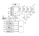
- FIG. 1 is a schematic configuration diagram of an engine control system
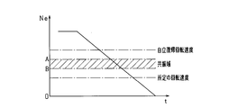
- FIG. 2 is a transition chart of the engine rotation speed during the rotation descent period.
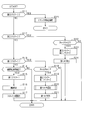
- FIG. 3 is a flowchart showing a process for stopping the engine speed
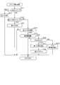
- FIG. 4 is a flowchart of the reverse torque setting process.
- FIG. 5 is a flowchart of the crank angle stop process.
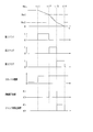
- FIG. 6 is a timing chart showing a mode of processing for stopping the engine rotation speed.
- FIG. 7 is a timing chart showing an aspect of the crank angle stop process
- FIG. 8 is a timing chart showing an aspect of the crank angle stop process.
- the present embodiment embodies an engine control system mounted on a vehicle.
- an electronic control unit hereinafter referred to as ECU
- ECU electronice control unit
- the engine 11 is a four-cycle engine that is driven by combustion of fuel such as gasoline and repeatedly performs intake, compression, expansion, and exhaust strokes.
- the engine 11 has four cylinders (cylinders) 12, and pistons 13 are accommodated in the respective cylinders 12.
- the engine 11 is appropriately provided with a fuel injection valve (not shown), an ignition device (not shown), and the like.
- a four-cylinder engine is shown, but the number of cylinders in the engine may be any number.
- the engine 11 is not limited to a gasoline engine, and may be a diesel engine.
- the cylinder 12 is supplied with air from the intake section 20.
- the intake section 20 has an intake manifold 21, and a throttle valve 22 that adjusts the intake air amount is provided upstream of the intake manifold 21.
- the engine 11 is integrally provided with an MG (motor generator) 30.
- the MG 30 is a rotating electrical machine that is driven as an electric motor and a generator.
- the crankshaft (engine output shaft) 14 of the engine 11 is mechanically connected to the crank pulley 15, and the rotation shaft 31 of the MG 30 is mechanically connected to the MG pulley 32.
- the crank pulley 15 and the MG pulley 32 are drivingly connected by a belt 33.
- the MG 30 is connected to the battery 35 via an inverter 34 that is a power conversion circuit.
- inverter 34 When MG 30 is driven as an electric motor, electric power is supplied from battery 35 to MG 30 via inverter 34 in accordance with a command from ECU 50. As a result, the MG 30 is driven.
- the inverter 34 may be provided with another ECU that receives a command from the ECU 50 and controls the power conversion circuit of the inverter 34.
- the MG 30 functions as a generator, the power generated by the MG 30 is converted from alternating current to direct current by the inverter 34 and then charged to the battery 35.
- the battery 35 is connected to an electric load 36 such as a lamp or an audio device.
- an auxiliary device 16 such as a water pump, a fuel pump, and an air conditioner compressor is mounted on the vehicle 10 as an auxiliary device that is driven by the rotation of the crankshaft 14.
- the auxiliary device includes a device in which the coupling state with the crankshaft 14 is intermittently connected by the clutch means in addition to the auxiliary device 16 that is drivingly connected to the engine 11 by a belt or the like.
- the ECU 50 is an electronic control device including a microcomputer including a well-known CPU, ROM, RAM, and the like.
- the ECU 50 controls the opening degree of the throttle valve 22 based on the detection results of various sensors provided in the system.
- Various engine controls such as fuel injection control by the fuel injection valve are performed.
- the ECU 50 includes a crank angle sensor 51 for detecting the rotational position of the crankshaft 14 and the engine rotational speed Ne, an accelerator sensor 52 for detecting the accelerator operation amount (accelerator opening), and a vehicle speed sensor for detecting the vehicle speed. 53, a brake sensor 54 for detecting the operation amount of the brake pedal, an in-cylinder pressure sensor 55 for detecting the in-cylinder pressure in the cylinder, and a battery sensor 56 for detecting the battery state of the battery 35 are connected. These signals are sequentially input to the ECU 50.
- the crank angle sensor 51 includes an electromagnetic pickup type rotational position detecting means for outputting a rectangular detection signal (crank pulse signal) for each predetermined crank angle (for example, at a cycle of 10 ° CA).
- the engine speed Ne is calculated from the time required every time the crankshaft 14 rotates by 10 ° CA. Further, according to the detection result of the rotational position, the rotational position of the crankshaft 14 with respect to a predetermined reference position (for example, compression top dead center) is calculated, and the stroke determination of the engine 11 is performed.
- the battery sensor 56 detects a voltage between terminals of the battery 35, a charge / discharge current, and the like. Based on these detected values, the remaining battery capacity (SOC) of the battery 35 is calculated.
- the ECU 50 performs idling stop control of the engine 11.
- the idling stop control stops combustion of the engine 11 when a predetermined automatic stop condition is satisfied, and then restarts the engine 11 when a predetermined restart condition is satisfied.
- the automatic stop condition includes, for example, that the vehicle speed of the host vehicle is in the engine automatic stop speed range (for example, vehicle speed ⁇ 10 km / h) and the accelerator operation is released or the brake operation is performed. included.
- the restart condition includes, for example, that an accelerator operation is started and a brake operation is released. It is also possible to adopt a configuration in which the engine control function and the idling stop function are implemented by separate ECUs 50.
- FIG. 2 shows the transition of the engine rotation speed Ne during the rotation drop period until the combustion of the engine 11 is stopped and the engine rotation speed Ne becomes zero.
- the engine rotation speed Ne passes through a self-recovery return rotation speed, an engine resonance range, and a predetermined rotation speed set in advance (for example, about 200 rpm).
- the self-recovery return rotational speed is a lower limit of the rotational speed at which the engine can be restarted by restarting the fuel supply without cranking while the combustion of the engine 11 is stopped, and is set to about 500 rpm, for example. .
- the engine resonance region refers to the region of the engine speed at which resonance occurs, and is set to 300 to 400 rpm, for example.
- resonance is a phenomenon that is excited when the excitation frequency corresponding to the engine rotation speed matches the resonance frequency of a power plant such as an engine body or an automatic transmission. Due to this phenomenon, vibration increases in the resonance region of the engine. Thus, the vibration in the resonance region is one factor of unpleasant vibration that occurs when the engine stops.
- the resonance region of the engine is provided on the lower rotation side than the idle rotation speed and on the higher rotation side than the cranking rotation speed of the conventional starter so that vibration due to resonance does not occur as much as possible. Therefore, after the combustion of the engine is stopped, the engine rotation speed Ne passes through the resonance region in the rotation descent period until the engine rotation speed Ne reaches zero.
- This embodiment shows the engine control in the rotation descent period until the combustion of the engine 11 is stopped and the engine rotation speed Ne becomes zero.
- the rotation descent period is divided into three periods based on the engine speed Ne. That is, the period from when the combustion of the engine 11 stops until the engine rotational speed Ne reaches the upper limit value of the predetermined rotational speed region including the resonance region (specifically, the boundary value A on the high rotation side of the resonance region).
- the first period is the second period when the engine rotation speed Ne is in the predetermined rotation speed range, and the engine rotation speed Ne is the lower limit value of the predetermined rotation speed area (specifically, the boundary value on the low rotation side of the resonance area).
- the period from the passage of B) until the engine speed Ne becomes zero was defined as the third period.
- engine control is performed according to each period.
- the opening of the throttle valve 22 is set to an opening larger than the idle rotation state. As a result, the amount of air necessary for restarting the engine is secured.
- a rotation descent process for increasing the descent speed of the engine rotation speed Ne in a predetermined rotation speed range including the resonance range is performed.
- the time for passing through the resonance region can be shortened, and vibrations caused by the resonance region can be suppressed.
- reverse rotation side torque (reverse torque) is applied to the crankshaft 14 so that the piston 13 is stopped at the crank rotation position in the first half of the expansion stroke when the rotation of the crankshaft 14 is stopped.
- FIG. 3 is a flowchart showing a processing procedure for engine control, and this processing is repeatedly executed by the ECU 50 at a predetermined cycle (for example, 10 ms).
- the first flag, the second flag, and the third flag in the figure correspond to the first period, the second period, and the third period, respectively, and whether or not the engine speed Ne belongs to each period. It is a flag which shows. Each flag indicates that the engine speed Ne belongs to the period when “1”, and does not belong to the period when “0”. In the initial setting, both are set to “0”.
- step S11 it is determined whether or not the third flag is “1”.
- step S12 it is determined whether or not the second flag is “1”.
- step S13 it is determined whether or not the first flag is “1”. If step S11 to step S13 are negative in the initial state, the process proceeds to step S14 to determine whether or not the engine automatic stop condition is satisfied. And when step S14 is denied, this process is complete
- step S14 determines whether the engine automatic stop condition is satisfied. If it is determined in step S14 that the engine automatic stop condition is satisfied, the process proceeds to step S15, and "1" is set to the first flag. In the subsequent step S16, the combustion of the engine 11 is stopped, and the process proceeds to step S17.
- step S17 the opening of the throttle valve 22 is set to an opening larger than the opening in the idle rotation state (specifically, the opening is set to + 10% or more with respect to the opening in the idle rotation state, for example, This process is terminated.
- step S17 corresponds to a throttle control unit.
- step S18 in which it is determined whether or not the engine rotational speed Ne is equal to or lower than a predetermined rotational speed Ne1 that is an upper limit value of the predetermined rotational speed range.
- the boundary value A on the high rotation side of the resonance region is set as the predetermined rotation speed Ne1. That is, in step S18, it is determined whether or not the engine rotation speed Ne has reached the boundary value A on the high rotation side of the resonance region.
- step S18 If it is determined in step S18 that the engine rotational speed Ne is greater than the predetermined rotational speed Ne1, this process is terminated. On the other hand, if it is determined in step S18 that the engine rotational speed Ne is equal to or lower than the predetermined rotational speed Ne1, that is, if the engine rotational speed Ne has shifted to the resonance range, the process proceeds to step S19, and the second flag is set to “1”. At the same time, the first flag is reset to “0”.
- step S20 first, reverse torque is set.
- the MG30 has a power generation function as a generator and a power running function as an electric motor, and applying reverse torque is executed using each function.
- the power running drive has a larger reverse torque than the regenerative power generation, and the regenerative power generation is superior in terms of fuel consumption compared to the power running drive. Therefore, it is desirable to use each function properly according to the driving state. In such a case, which function is used is determined based on various parameters.
- the MG 30 depends on the amount of power consumed by the electrical load 36 connected to the battery 35, the state of the remaining capacity of the battery 35, the amount of torque required to apply reverse torque, and the load due to the operation of the auxiliary machine 16. The regenerative power generation and power running drive are selected.
- Fig. 4 shows a flowchart of reverse torque setting.
- step S31 it is determined whether the power consumption of the electrical load 36 is equal to or greater than a predetermined value.
- the electric load 36 include lamps and an electric pump. More specifically, it is determined whether or not the brake pedal is depressed. When the brake pedal is depressed, the brake lamp is lit, and the power consumption is increased. If it is determined in step S31 that the brake pedal is depressed, the process proceeds to step S32, and it is determined to apply reverse torque by regenerative power generation. In this case, since the amount of power consumed by the electric load 36 is large, vibration can be suppressed while reducing the burden on the battery 35 by using regenerative power generation.
- step S31 determines whether or not the SOC of the battery 35 is greater than or equal to the threshold Th1.
- step S33 determines whether or not the SOC of the battery 35 is greater than or equal to the threshold Th1.
- the threshold Th1 may be changed as appropriate. For example, when the threshold Th1 is equal to or greater than the threshold Th1, it may be a value that can be determined to be a fully charged state.
- an estimation method based on an open circuit voltage (OCV) and a calculation method based on current integration are used.
- OCV open circuit voltage
- the SOC is estimated using the acquired value and a map representing the correspondence relationship between the open-circuit voltage and the SOC, and the charge / discharge current flowing through the battery 35 is acquired.
- the SOC is calculated by calculating the obtained value.
- reverse torque by power running drive it is good also as a setting which makes reverse torque large, so that electric remaining amount is large. In this case, it is considered that the passing time through the resonance region can be further shortened and the vibration suppressing effect is enhanced.
- step S33 when step S33 is denied, it progresses to step S34 and a function is selected according to the request
- step S34 the process proceeds to step S35, and a function is selected according to the load of the auxiliary machine 16. For example, it is determined whether or not the load due to the operation of the auxiliary machine 16 is greater than or equal to the threshold Th3. When it determines with it being more than threshold value Th3 by step S35, it progresses to step S32 and determines providing reverse torque by regenerative power generation. In such a case, the power consumption of the electric load 36 is less than a predetermined value (step S31: NO), but regenerative power generation is selected in view of other parameters indicating the driving state of the vehicle.
- step S35 when step S35 is denied, it progresses to step S36 and determines giving reverse torque by power running drive. As described above, after regenerative power generation or power running drive is determined based on the parameters, the process proceeds to step S21 in FIG. 3 to apply reverse torque.
- step S31 when step S31 is NO, it may be configured to proceed to step S36 without selecting the determination of step S33 to step S35 and select power running drive. That is, when the electric power consumption of the electric load 36 is less than a predetermined value, a configuration in which reverse torque is applied by power running drive may be used.
- the application of reverse torque by power running drive corresponds to the first rotation descent process
- the application of reverse torque by regenerative power generation corresponds to the second rotation descent process
- step S12 of FIG. 3 determines whether the second flag is “1”
- the process proceeds to step S22, and whether the engine rotational speed Ne is smaller than the predetermined rotational speed Ne2 that is the lower limit value of the predetermined rotational speed range. Determine whether or not.
- the boundary value B on the low rotation side of the resonance region is set as the predetermined rotation speed Ne2. That is, in step S22, it is determined whether or not the engine rotation speed Ne has passed the boundary value B on the low rotation side of the resonance region.
- step S22 If it is determined in step S22 that the engine rotational speed Ne is smaller than the predetermined rotational speed Ne2, that is, if the engine rotational speed Ne has shifted to the third period, the process proceeds to step S23, and the third flag is set to “1”. At the same time, the second flag is reset to “0”. In subsequent step S24, the reverse torque applied in step S21 is stopped. On the other hand, if it is determined in step S22 that the engine rotational speed Ne is equal to or higher than the predetermined rotational speed Ne2, the present process is terminated.
- step S18 and step S22 is corresponded to the resonance area determination part which determines passing through the resonance area of an engine.
- the process of step S20 and step S21 is equivalent to a rotation descent control part.
- step S11 determines whether the third flag is “1”
- the process proceeds to step S25 to execute the subroutine shown in FIG. That is, when the engine speed Ne shifts to the third period, the crank angle stop process for suppressing the reverse rotation of the engine is performed.
- reverse torque is applied at a predetermined timing based on the engine speed so that the piston 13 is stopped at the first half of the expansion stroke, that is, the piston 13 of the next combustion cylinder is stopped at the first half of the compression stroke.
- a backup process for applying a torque (forward torque) on the forward rotation side to the engine output shaft is also executed. That is, in the crank angle stop process, control is performed so that the piston 13 does not stop at the latter half of the compression stroke, that is, the piston 13 does not stop at the position where the compression reaction force is generated.
- step S41 of FIG. 5 it is first determined whether or not it is time to apply a positive torque to the engine output shaft. This step is affirmed when it is determined that the backup process is to be executed, and step S41 is denied in the initial setting.
- step S42 it is determined whether or not it is time to apply a reverse torque to the engine output shaft. In the present embodiment, for example, when the engine rotation speed Ne when the piston 13 is positioned at the compression TDC is equal to or lower than the predetermined rotation speed Ne3, it is determined that it is the timing to apply the reverse torque. If it is determined that it is time to apply reverse torque, the process proceeds to step S43, where reverse torque is applied to the engine output shaft, and this process ends.
- the predetermined rotational speed Ne3 is determined to stop rotation of the engine output shaft by applying reverse torque from the timing when the piston is positioned at the compression TDC until the piston passes the first half of the expansion stroke. Rotation speed.
- the predetermined rotational speed Ne3 is set to a value smaller than the predetermined rotational speed Ne2 that is the lower limit value of the predetermined rotational speed range.
- step S42 determines whether or not the timing to apply the reverse torque.
- step S44 determines whether or not the reverse torque is applied.
- step S44 determines whether the reverse torque is applied
- the process proceeds to step S45, where the crank rotational position detected by the crank angle sensor 51 is set to a predetermined angle (for example, ATDC 70 ° CA). It is determined whether or not. If it is determined that the rotational position is the predetermined angle, the process proceeds to step S46, and it is determined whether or not the engine rotational speed Ne is equal to or lower than the predetermined rotational speed Ne4. On the other hand, when step S45 is denied, this process is complete
- a predetermined angle for example, ATDC 70 ° CA
- step S46 If it is determined in step S46 that the engine rotational speed Ne is equal to or lower than the predetermined rotational speed Ne4, that is, if it is determined that the piston 13 stops in the first half of the expansion stroke, the process proceeds to step S47, and is given in step S43. Instructs to stop reverse torque. As a result, the reverse torque applied to the engine output shaft is stopped. Then, it progresses to step S48, a 3rd flag is reset to "0", and this process is complete
- step S45 and step S46 correspond to a stop determination unit.
- the predetermined rotational speed Ne4 at the predetermined angle can be arbitrarily changed, and can be determined whether or not the piston 13 actually stops at the crank rotational position until the first half of the expansion stroke after applying the reverse torque in step S43. If it is.
- step S46 determines whether the engine rotational speed Ne is greater than the predetermined rotational speed Ne4 or not stop at the first half of the expansion stroke. That is, it is determined that the backup process is executed.
- this process is executed and the crank rotational position is at a predetermined rotational angle (for example, ATDC 90 ° CA), it is determined that it is time to apply a positive torque to the engine output shaft (step) S41: YES).
- step S41 If step S41 is affirmed, the process proceeds to step S50, a positive torque is applied, and the process is terminated. Thereafter, the process proceeds to step S42 again, and the crank angle stop process is executed until the third flag is finally reset to “0”.
- the first flag is set to “1”.
- the opening degree of the throttle valve 22 is controlled to be larger than the opening degree in the idle state.
- the second flag is set to “1” and at the same time the first flag is reset to “0”.
- a reverse torque is applied to the engine output shaft as a rotation descent process.
- the third flag is set to “1” and at the same time the second flag is reset to “0”.
- the rotation descent process is stopped, and the crank angle stop process is executed in the subsequent third period.
- the timing t14 the engine rotational speed Ne becomes zero.
- FIGS. 7 shows a case where step S46 is affirmed and only reverse torque is applied in the third period
- FIG. 8 shows that step S46 is negated and positive torque is applied in addition to reverse torque in the third period. Shows the case.
- changes in the in-cylinder pressure of each cylinder are shown. The in-cylinder pressure increases as the piston 13 approaches the compression TDC, and becomes maximum at the compression TDC. Further, the maximum value of the in-cylinder pressure decreases as the engine speed Ne decreases. Note that the firing order of each cylinder is # 1 ⁇ # 2 ⁇ # 3 ⁇ # 4 for convenience of explanation.
- a four-cylinder engine is shown as a multi-cylinder engine.
- the piston 13 of one cylinder stops at the position of the first half period of the expansion stroke
- the piston 13 of the other cylinder does not stop at the position of the second half period of the compression stroke, that is, the position where the compression reaction force is generated.
- the opening of the throttle valve 22 is set to an opening larger than the opening in the idle rotation state, which is necessary when the engine is restarted. A sufficient amount of air can be secured. Further, by applying the reverse torque using the MG 30 so that the decrease rate of the engine rotation speed is increased in the resonance region, it is possible to shorten the time for passing through the resonance region. In this case, in a state where the throttle opening is large, there is a concern about an increase in vibration in the resonance region, but an increase in vibration can be suppressed by reducing the passage time of the resonance region. As a result, in a vehicle having an idling stop function, it is possible to ensure startability at the time of restart while suppressing generation of vibration at the time of automatic engine stop.
- the throttle valve 22 is configured to have an opening larger than the opening in the idle rotation state. Therefore, even when the restart condition is satisfied immediately after the combustion is stopped, a sufficient amount of air can be secured and the startability at the time of restart is improved.
- a reverse torque is applied using MG30.
- the regenerative power generation and the power running drive can be selected.
- the power running drive has a larger reverse torque than the regenerative power generation, and the regenerative power generation is superior in terms of fuel consumption compared to the power running drive.
- the regenerative power generation and the power running drive can be selected according to the power consumption of the electric load 36 connected to the battery 35.
- the battery 35 is burdened and reverse torque is applied by regenerative power generation. Thereby, it is possible to suppress vibration while keeping the power state of the battery 35 stable.
- the regenerative power generation and the power running driving can be selected based on the remaining electric power of the battery 35.
- the threshold value Th1 when the remaining amount of electricity is equal to or greater than the threshold value Th1, reverse torque is applied by powering drive.
- the remaining amount of electricity in the battery 35 is large, there is a concern about overcharging of the battery 35 by causing the rotating electric machine to generate regenerative power.
- by applying the reverse torque by powering drive it is possible to suppress vibration caused by the resonance region without damaging the battery 35.
- the MG 30 is used to apply reverse torque from the compression top dead center.
- the piston 13 can be stopped at the first half of the expansion stroke by applying reverse torque. Thereby, the vibration accompanying it can be reduced by suppressing generation
- the engine 11 is determined to be the previous compression top dead center based on the engine rotation speed at the compression top dead center being equal to or less than a predetermined value.
- the predetermined value is a value that is determined by stopping the piston 13 at the first half of the expansion stroke by applying reverse torque. Therefore, the piston 13 can be stopped at a desired position, and the vibration accompanying the reverse rotation of the engine can be reduced.
- a stop determination unit that determines whether or not the piston 13 actually stops at a desired position is provided, and when it is determined to stop at the desired position, the reverse torque application is stopped. It was. In this case, when the rotation of the engine stops at the first half of the expansion stroke, the application of reverse torque is released. Thereby, reverse rotation of the engine due to reverse torque can be prevented.
- backup processing was provided for stop control in the third period. That is, when the stop determination unit determines that the piston 13 does not stop at a desired position, a positive torque is once applied so that the piston 13 can get over the next compression TDC. Then, when the compression TDC is reached, a reverse torque is applied again to stop the piston at the first half of the expansion stroke. Thereby, the piston 13 can be more reliably stopped at the first half of the expansion stroke, and the vibration suppressing effect can be enhanced.
- the reverse torque is applied in the resonance region using the MG 30, and the reverse torque by the crank stop process is applied in the third period, or Forward / reverse torque was applied.
- the vibration accompanying the reverse rotation of the engine can be suppressed.
- the adverse effect of the vibration in the resonance region on the reverse rotation vibration is reduced.
- the vibration generated between the stop of the combustion of the engine 11 and the stop of the rotation of the engine 11 is synergistically. Can be suppressed.
- the MG30 is used as an auxiliary device to apply reverse torque, but any auxiliary device that can apply reverse torque to the engine output shaft may be used.
- the auxiliary equipment include auxiliary equipment 16 such as a water pump and a fuel pump. In this case, even in a vehicle not equipped with the MG 30, reverse torque can be applied using a device that is normally provided in the vehicle. For this reason, there is no need to provide a new device separately, which is economical.
- the reverse torque is applied with the predetermined rotation speed range as the resonance range. That is, the upper limit value of the predetermined rotation speed range is set as the boundary value A on the high rotation side of the resonance range, and the lower limit value of the predetermined rotation speed range is set as the boundary value B on the low rotation side of the resonance range.
- the predetermined rotational speed region may be configured so as to include the resonance region.
- the predetermined rotational speed region may be determined by setting the predetermined rotational speed higher than the resonance region as the upper limit value.
- step S18 of FIG. 3 it is determined whether or not the engine rotational speed Ne is equal to or lower than a predetermined rotational speed Ne1 set higher than the boundary value A of the resonance region, and step S18 is YES. If so, the application of reverse torque is started.
- the reverse torque is applied before reaching the resonance range, thereby improving the response to the descending speed due to the reverse torque near the boundary value A in the resonance range. Can do. As a result, the passage time of the resonance region is further shortened, and the vibration suppressing effect is enhanced.
- the predetermined rotational speed range may be determined with the self-recovery return rotational speed higher than the resonance area as the upper limit value.
- step S18 of FIG. 3 it is determined whether or not the engine rotational speed Ne is equal to or lower than the predetermined rotational speed Ne1 set to the self-recovery return rotational speed. If step S18 is YES, reverse torque is applied. Start.
- the engine rotational speed Ne1 exceeds the predetermined rotation speed Ne1 at the beginning when the engine starts to stop combustion, the decrease speed of the engine rotation speed is not increased, and the possibility of the engine self-recovery is possible. Can be expected. As a result, the power consumption required for restart can be reduced, the response to the descent speed in the resonance region can be improved, and the vibration suppression effect can be enhanced.
- the predetermined rotational speed range may be determined by setting a predetermined rotational speed set in advance on the lower rotation side than the resonance range as a lower limit value.
- step S22 of FIG. 3 it is determined whether or not the engine rotational speed Ne is lower than a predetermined rotational speed Ne2, and if step S22 is YES, the application of reverse torque is stopped.
- step S22 it is possible to expect the possibility of restarting the engine due to cranking without increasing the decrease rate of the engine rotation speed while the engine rotation speed is between a predetermined rotation speed set in advance and zero. .
- restartability can be ensured while suppressing vibration in the resonance region.
- the predetermined rotational speed range may be set by combining the setting of the upper limit value and the lower limit value of the predetermined rotational speed range described above. For example, it is possible to set the upper limit value of the predetermined rotation speed range to a self-recovery return rotation speed higher than the resonance range and the lower limit value to a predetermined rotation speed set in advance on the lower rotation side than the resonance range. In such a case, it is possible to pass through the rotational speed region where the engine cannot be restarted at an early stage by means of fuel supply or cranking. On the other hand, in the region where the engine can be restarted, the decrease speed of the engine speed is not increased. As a result, restartability can be ensured while suppressing vibration in the resonance region.
- the power consumption of the electrical load 36 connected to the battery 35 the state of the remaining capacity of the battery 35, the required torque amount required for the reverse torque application, and the auxiliary machine 16
- the regenerative power generation and the power running drive of the MG 30 are selected according to the load caused by the operation of the above, but the configuration may be selected according to other parameters. Other parameters include the rotational speed of the MG 30 and the like.
- priority may be set between the above parameters. For example, the determination based on the driving state of the electric load 36 may be given the highest priority, followed by the state of the remaining capacity of the battery 35, the required torque amount necessary for applying reverse torque, and the load due to the operation of the auxiliary machine 16.
- the SOC of the battery 35 is used as the state of the remaining capacity of the battery 35.
- the present invention is not limited to this.
- the voltage between the terminals of the battery 35 may be used.
- the reverse torque is applied from the timing t31 to the timing t33 in FIG. 8, but the reverse torque is stopped at the time of the stop determination at the timing t32. Good.
- a positive torque is applied from the timing t33 to the timing t34 (timing when the second cylinder (# 2) reaches the compression TDC).
- the period for applying the positive torque is not limited to this, and any structure may be used as long as the positive torque is applied so that the piston (here, the second cylinder (# 2)) can overcome the compression TDC.
- the configuration may be such that positive torque application is stopped.
- the magnitude of the reverse torque applied in the crank angle stop process may be determined in advance as the amount of torque required to stop the piston 13 at the first half of the expansion stroke. Also, means for predicting the stop position of the piston 13 every moment when the rotation of the engine stops is provided, and even if reverse torque is applied while performing feedback control for adjusting the torque amount based on the predicted stop position. Good.
- the magnitudes of the reverse torque and the positive torque applied in the crank angle stop process may be appropriately changed, and may be the same torque amount or different torque amounts. Further, the magnitudes of the first reverse torque and the second reverse torque when the backup process is performed may be appropriately changed. For example, the second reverse torque may be made larger than the first reverse torque, and according to this configuration, it is considered that the piston can be more reliably stopped at a desired position.
- the crank angle position at which the predetermined rotation speed Ne3 is set is not limited to the compression TDC, and the engine rotation speed Ne at other crank angle positions may be set as a threshold value for determination.
- the application of reverse torque may be started from the crank angle position at which the threshold is set.
- the predetermined rotation speed Ne3 is provided as a threshold value for the engine rotation speed as the determination of the timing for applying the reverse torque.
- the present invention is not limited to this method.
- a method may be used in which the timing is determined from the decrease in the engine rotational speed Ne.
- the ECU 50 calculates the rotational speed drop amount ⁇ Ne from the engine rotational speed Ne for each compression TDC, and estimates the compression TDC (i) that is predicted to be less than zero.
- the timing at which the compression TDC (i ⁇ 1) immediately before the compression TDC (i) is reached can be set as the reverse torque application timing.
- the above-described control during the rotation descent period until the engine rotation speed becomes zero is not limited to the automatic engine stop, but may be performed in the case of a stop by the driver's ignition switch operation. Moreover, the case of the stop in the vehicle which does not have an idling stop function may be sufficient.
Abstract
Selon l'invention, après que la combustion d'un moteur (11) s'est arrêtée et pendant une période de réduction de vitesse quand la vitesse de moteur chute à zéro, une ECU (50) ouvre un papillon des gaz (22) plus largement que pendant la rotation au ralenti du moteur (11). De plus, l'ECU (50) détermine, pendant la période de réduction de vitesse, si la vitesse de moteur s'inscrit dans une plage de vitesse de rotation prescrite comprenant au moins une plage de résonance pour le moteur à combustion (11), et, s'il est déterminé que la vitesse de moteur s'inscrit dans la plage de vitesse de rotation prescrite, réalise une réduction de vitesse, ce ce par quoi le rythme de réduction de la vitesse de moteur est temporairement accru.
Priority Applications (3)
| Application Number | Priority Date | Filing Date | Title |
|---|---|---|---|
| US16/099,875 US10655587B2 (en) | 2016-05-10 | 2017-04-27 | Engine stop/start control apparatus |
| DE112017002438.2T DE112017002438B4 (de) | 2016-05-10 | 2017-04-27 | Kraftmaschinenstopp-/-startsteuerungsvorrichtung |
| CN201780028820.3A CN109196205A (zh) | 2016-05-10 | 2017-04-27 | 发动机停止起动控制装置 |
Applications Claiming Priority (2)
| Application Number | Priority Date | Filing Date | Title |
|---|---|---|---|
| JP2016-094757 | 2016-05-10 | ||
| JP2016094757A JP2017203401A (ja) | 2016-05-10 | 2016-05-10 | エンジン停止始動制御装置 |
Publications (1)
| Publication Number | Publication Date |
|---|---|
| WO2017195629A1 true WO2017195629A1 (fr) | 2017-11-16 |
Family
ID=60267994
Family Applications (1)
| Application Number | Title | Priority Date | Filing Date |
|---|---|---|---|
| PCT/JP2017/016761 WO2017195629A1 (fr) | 2016-05-10 | 2017-04-27 | Dispositif de commande de démarrage/arrêt de moteur |
Country Status (5)
| Country | Link |
|---|---|
| US (1) | US10655587B2 (fr) |
| JP (1) | JP2017203401A (fr) |
| CN (1) | CN109196205A (fr) |
| DE (1) | DE112017002438B4 (fr) |
| WO (1) | WO2017195629A1 (fr) |
Cited By (1)
| Publication number | Priority date | Publication date | Assignee | Title |
|---|---|---|---|---|
| CN111448116A (zh) * | 2017-12-15 | 2020-07-24 | 日产自动车株式会社 | 电动装置和电动装置的控制方法 |
Families Citing this family (3)
| Publication number | Priority date | Publication date | Assignee | Title |
|---|---|---|---|---|
| JP2017203402A (ja) * | 2016-05-10 | 2017-11-16 | 株式会社デンソー | エンジン制御装置 |
| EP4215740A4 (fr) | 2020-09-16 | 2023-11-15 | Nissan Motor Co., Ltd. | Procédé de commande de moteur à combustion interne et dispositif de commande de moteur à combustion interne |
| JP2023154668A (ja) * | 2022-04-07 | 2023-10-20 | トヨタ自動車株式会社 | 車両の制御装置 |
Citations (2)
| Publication number | Priority date | Publication date | Assignee | Title |
|---|---|---|---|---|
| JP2011127504A (ja) * | 2009-12-17 | 2011-06-30 | Mitsubishi Electric Corp | エンジンの自動始動装置 |
| WO2013145089A1 (fr) * | 2012-03-26 | 2013-10-03 | トヨタ自動車株式会社 | Dispositif de commande d'entraînement pour véhicule hybride |
Family Cites Families (15)
| Publication number | Priority date | Publication date | Assignee | Title |
|---|---|---|---|---|
| JP3577979B2 (ja) | 1999-03-04 | 2004-10-20 | 三菱自動車工業株式会社 | 内燃機関の停止制御装置 |
| EP1666712B1 (fr) * | 2001-01-26 | 2008-09-03 | Denso Corporation | Appareil de commande de moteur |
| EP1367256B1 (fr) * | 2002-05-14 | 2007-04-18 | Ford Global Technologies, LLC | Méthode pour préparer un moteur a combustion au démarrage |
| JP3770235B2 (ja) * | 2003-01-28 | 2006-04-26 | トヨタ自動車株式会社 | 内燃機関の停止位置推定装置 |
| JP3841058B2 (ja) * | 2003-03-27 | 2006-11-01 | マツダ株式会社 | エンジンの始動装置 |
| US7217221B2 (en) * | 2004-05-14 | 2007-05-15 | General Motors Corporation | Method for active engine stop of a hybrid electric vehicle |
| JP4747741B2 (ja) * | 2005-08-30 | 2011-08-17 | 日産自動車株式会社 | 内燃機関の制御装置及び制御方法 |
| JP5234396B2 (ja) * | 2006-11-13 | 2013-07-10 | 現代自動車株式会社 | ハイブリッド電気車両のエンジン停止位置の制御方法 |
| JP4636199B2 (ja) * | 2008-10-04 | 2011-02-23 | 株式会社デンソー | エンジン自動停止始動制御装置 |
| JP5310113B2 (ja) | 2009-03-04 | 2013-10-09 | 日産自動車株式会社 | 内燃機関 |
| JP2012127246A (ja) * | 2010-12-15 | 2012-07-05 | Suzuki Motor Corp | エンジンの停止時制御装置 |
| CN103282632B (zh) * | 2010-12-27 | 2015-11-25 | 日产自动车株式会社 | 内燃发动机的起动控制方法及起动控制装置 |
| JP5746880B2 (ja) | 2011-02-21 | 2015-07-08 | ダイハツ工業株式会社 | 内燃機関の制御装置 |
| GB2489499B (en) * | 2011-03-31 | 2016-08-24 | Ford Global Tech Llc | A method and system for controlling an engine |
| JP6379016B2 (ja) | 2014-11-14 | 2018-08-22 | パナソニック株式会社 | 戸枠装置、これのキャップ部材及び戸枠装置の施工方法 |
-
2016
- 2016-05-10 JP JP2016094757A patent/JP2017203401A/ja active Pending
-
2017
- 2017-04-27 DE DE112017002438.2T patent/DE112017002438B4/de active Active
- 2017-04-27 CN CN201780028820.3A patent/CN109196205A/zh active Pending
- 2017-04-27 WO PCT/JP2017/016761 patent/WO2017195629A1/fr active Application Filing
- 2017-04-27 US US16/099,875 patent/US10655587B2/en active Active
Patent Citations (2)
| Publication number | Priority date | Publication date | Assignee | Title |
|---|---|---|---|---|
| JP2011127504A (ja) * | 2009-12-17 | 2011-06-30 | Mitsubishi Electric Corp | エンジンの自動始動装置 |
| WO2013145089A1 (fr) * | 2012-03-26 | 2013-10-03 | トヨタ自動車株式会社 | Dispositif de commande d'entraînement pour véhicule hybride |
Cited By (5)
| Publication number | Priority date | Publication date | Assignee | Title |
|---|---|---|---|---|
| CN111448116A (zh) * | 2017-12-15 | 2020-07-24 | 日产自动车株式会社 | 电动装置和电动装置的控制方法 |
| KR20200089737A (ko) * | 2017-12-15 | 2020-07-27 | 닛산 지도우샤 가부시키가이샤 | 전동 장치 및 전동 장치의 제어 방법 |
| EP3725612A4 (fr) * | 2017-12-15 | 2020-12-16 | Nissan Motor Co., Ltd. | Dispositif électrique et procédé de commande de dispositif électrique |
| KR102280500B1 (ko) | 2017-12-15 | 2021-07-26 | 닛산 지도우샤 가부시키가이샤 | 전동 장치 및 전동 장치의 제어 방법 |
| US11338791B2 (en) | 2017-12-15 | 2022-05-24 | Nissan Motor Co., Ltd. | Electric device and method for controlling electric device |
Also Published As
| Publication number | Publication date |
|---|---|
| DE112017002438T5 (de) | 2019-01-24 |
| US10655587B2 (en) | 2020-05-19 |
| DE112017002438B4 (de) | 2023-07-06 |
| US20190153991A1 (en) | 2019-05-23 |
| CN109196205A (zh) | 2019-01-11 |
| JP2017203401A (ja) | 2017-11-16 |
Similar Documents
| Publication | Publication Date | Title |
|---|---|---|
| JP6642255B2 (ja) | エンジン制御装置 | |
| JP4293138B2 (ja) | 内燃機関の制御装置及びその制御装置を備えた自動車 | |
| US7840337B2 (en) | Method for controlling an overrun condition of a hybrid vehicle and hybrid vehicle | |
| WO2017195629A1 (fr) | Dispositif de commande de démarrage/arrêt de moteur | |
| JP4075699B2 (ja) | 車両の制御装置 | |
| WO2017195630A1 (fr) | Dispositif de commande de moteur | |
| JP2013194584A (ja) | 車両搭載エンジンの始動装置 | |
| JP4165237B2 (ja) | 内燃機関の始動制御装置 | |
| WO2017195628A1 (fr) | Dispositif de commande de moteur | |
| JP2009215887A (ja) | エンジン回転停止制御装置 | |
| JP2001280185A (ja) | 内燃機関の始動制御装置およびこれを備える車両 | |
| JP6891486B2 (ja) | ハイブリッド車両の駆動制御装置 | |
| US11136930B2 (en) | Engine start control device | |
| JP7292789B2 (ja) | 車両制御装置 | |
| JP2013124082A (ja) | ハイブリッド電気自動車の制御装置 | |
| US20230303075A1 (en) | Vehicle controller and method for controlling vehicle | |
| WO2015159876A1 (fr) | Dispositif de commande pour véhicules | |
| US20230271603A1 (en) | Controller for hybrid electric vehicle and method for controlling hybrid electric vehicle | |
| JP2004332681A (ja) | 車両のエンジン始動装置 |
Legal Events
| Date | Code | Title | Description |
|---|---|---|---|
| 121 | Ep: the epo has been informed by wipo that ep was designated in this application |
Ref document number: 17795990 Country of ref document: EP Kind code of ref document: A1 |
|
| 122 | Ep: pct application non-entry in european phase |
Ref document number: 17795990 Country of ref document: EP Kind code of ref document: A1 |