WO2017195629A1 - Engine stop/start control device - Google Patents
Engine stop/start control device Download PDFInfo
- Publication number
- WO2017195629A1 WO2017195629A1 PCT/JP2017/016761 JP2017016761W WO2017195629A1 WO 2017195629 A1 WO2017195629 A1 WO 2017195629A1 JP 2017016761 W JP2017016761 W JP 2017016761W WO 2017195629 A1 WO2017195629 A1 WO 2017195629A1
- Authority
- WO
- WIPO (PCT)
- Prior art keywords
- engine
- rotation
- rotation speed
- speed
- predetermined
- Prior art date
Links
Images


Classifications
-
- F—MECHANICAL ENGINEERING; LIGHTING; HEATING; WEAPONS; BLASTING
- F02—COMBUSTION ENGINES; HOT-GAS OR COMBUSTION-PRODUCT ENGINE PLANTS
- F02D—CONTROLLING COMBUSTION ENGINES
- F02D41/00—Electrical control of supply of combustible mixture or its constituents
- F02D41/02—Circuit arrangements for generating control signals
- F02D41/04—Introducing corrections for particular operating conditions
- F02D41/042—Introducing corrections for particular operating conditions for stopping the engine
-
- F—MECHANICAL ENGINEERING; LIGHTING; HEATING; WEAPONS; BLASTING
- F02—COMBUSTION ENGINES; HOT-GAS OR COMBUSTION-PRODUCT ENGINE PLANTS
- F02N—STARTING OF COMBUSTION ENGINES; STARTING AIDS FOR SUCH ENGINES, NOT OTHERWISE PROVIDED FOR
- F02N11/00—Starting of engines by means of electric motors
- F02N11/08—Circuits or control means specially adapted for starting of engines
- F02N11/0814—Circuits or control means specially adapted for starting of engines comprising means for controlling automatic idle-start-stop
- F02N11/0818—Conditions for starting or stopping the engine or for deactivating the idle-start-stop mode
-
- B—PERFORMING OPERATIONS; TRANSPORTING
- B60—VEHICLES IN GENERAL
- B60W—CONJOINT CONTROL OF VEHICLE SUB-UNITS OF DIFFERENT TYPE OR DIFFERENT FUNCTION; CONTROL SYSTEMS SPECIALLY ADAPTED FOR HYBRID VEHICLES; ROAD VEHICLE DRIVE CONTROL SYSTEMS FOR PURPOSES NOT RELATED TO THE CONTROL OF A PARTICULAR SUB-UNIT
- B60W10/00—Conjoint control of vehicle sub-units of different type or different function
- B60W10/04—Conjoint control of vehicle sub-units of different type or different function including control of propulsion units
- B60W10/06—Conjoint control of vehicle sub-units of different type or different function including control of propulsion units including control of combustion engines
-
- F—MECHANICAL ENGINEERING; LIGHTING; HEATING; WEAPONS; BLASTING
- F02—COMBUSTION ENGINES; HOT-GAS OR COMBUSTION-PRODUCT ENGINE PLANTS
- F02D—CONTROLLING COMBUSTION ENGINES
- F02D29/00—Controlling engines, such controlling being peculiar to the devices driven thereby, the devices being other than parts or accessories essential to engine operation, e.g. controlling of engines by signals external thereto
- F02D29/02—Controlling engines, such controlling being peculiar to the devices driven thereby, the devices being other than parts or accessories essential to engine operation, e.g. controlling of engines by signals external thereto peculiar to engines driving vehicles; peculiar to engines driving variable pitch propellers
-
- F—MECHANICAL ENGINEERING; LIGHTING; HEATING; WEAPONS; BLASTING
- F02—COMBUSTION ENGINES; HOT-GAS OR COMBUSTION-PRODUCT ENGINE PLANTS
- F02D—CONTROLLING COMBUSTION ENGINES
- F02D41/00—Electrical control of supply of combustible mixture or its constituents
- F02D41/0002—Controlling intake air
-
- F—MECHANICAL ENGINEERING; LIGHTING; HEATING; WEAPONS; BLASTING
- F02—COMBUSTION ENGINES; HOT-GAS OR COMBUSTION-PRODUCT ENGINE PLANTS
- F02D—CONTROLLING COMBUSTION ENGINES
- F02D41/00—Electrical control of supply of combustible mixture or its constituents
- F02D41/02—Circuit arrangements for generating control signals
- F02D41/04—Introducing corrections for particular operating conditions
- F02D41/06—Introducing corrections for particular operating conditions for engine starting or warming up
- F02D41/062—Introducing corrections for particular operating conditions for engine starting or warming up for starting
-
- F—MECHANICAL ENGINEERING; LIGHTING; HEATING; WEAPONS; BLASTING
- F02—COMBUSTION ENGINES; HOT-GAS OR COMBUSTION-PRODUCT ENGINE PLANTS
- F02D—CONTROLLING COMBUSTION ENGINES
- F02D43/00—Conjoint electrical control of two or more functions, e.g. ignition, fuel-air mixture, recirculation, supercharging or exhaust-gas treatment
-
- F—MECHANICAL ENGINEERING; LIGHTING; HEATING; WEAPONS; BLASTING
- F02—COMBUSTION ENGINES; HOT-GAS OR COMBUSTION-PRODUCT ENGINE PLANTS
- F02D—CONTROLLING COMBUSTION ENGINES
- F02D45/00—Electrical control not provided for in groups F02D41/00 - F02D43/00
-
- F—MECHANICAL ENGINEERING; LIGHTING; HEATING; WEAPONS; BLASTING
- F02—COMBUSTION ENGINES; HOT-GAS OR COMBUSTION-PRODUCT ENGINE PLANTS
- F02N—STARTING OF COMBUSTION ENGINES; STARTING AIDS FOR SUCH ENGINES, NOT OTHERWISE PROVIDED FOR
- F02N11/00—Starting of engines by means of electric motors
- F02N11/04—Starting of engines by means of electric motors the motors being associated with current generators
-
- F—MECHANICAL ENGINEERING; LIGHTING; HEATING; WEAPONS; BLASTING
- F02—COMBUSTION ENGINES; HOT-GAS OR COMBUSTION-PRODUCT ENGINE PLANTS
- F02N—STARTING OF COMBUSTION ENGINES; STARTING AIDS FOR SUCH ENGINES, NOT OTHERWISE PROVIDED FOR
- F02N11/00—Starting of engines by means of electric motors
- F02N11/08—Circuits or control means specially adapted for starting of engines
- F02N11/0814—Circuits or control means specially adapted for starting of engines comprising means for controlling automatic idle-start-stop
- F02N11/0844—Circuits or control means specially adapted for starting of engines comprising means for controlling automatic idle-start-stop with means for restarting the engine directly after an engine stop request, e.g. caused by change of driver mind
-
- B—PERFORMING OPERATIONS; TRANSPORTING
- B60—VEHICLES IN GENERAL
- B60W—CONJOINT CONTROL OF VEHICLE SUB-UNITS OF DIFFERENT TYPE OR DIFFERENT FUNCTION; CONTROL SYSTEMS SPECIALLY ADAPTED FOR HYBRID VEHICLES; ROAD VEHICLE DRIVE CONTROL SYSTEMS FOR PURPOSES NOT RELATED TO THE CONTROL OF A PARTICULAR SUB-UNIT
- B60W2510/00—Input parameters relating to a particular sub-units
- B60W2510/06—Combustion engines, Gas turbines
- B60W2510/0638—Engine speed
-
- F—MECHANICAL ENGINEERING; LIGHTING; HEATING; WEAPONS; BLASTING
- F02—COMBUSTION ENGINES; HOT-GAS OR COMBUSTION-PRODUCT ENGINE PLANTS
- F02N—STARTING OF COMBUSTION ENGINES; STARTING AIDS FOR SUCH ENGINES, NOT OTHERWISE PROVIDED FOR
- F02N2200/00—Parameters used for control of starting apparatus
- F02N2200/02—Parameters used for control of starting apparatus said parameters being related to the engine
- F02N2200/022—Engine speed
Definitions
- the present disclosure relates to an engine stop / start control device.
- the throttle valve opening is made smaller than the predetermined opening, and the air supply to the cylinder is restricted.
- an air amount sufficient for combustion cannot be secured, resulting in deterioration of restart.
- Patent Document 1 when idling stop is performed, if the throttle valve is opened and air is introduced before the rotation of the engine output shaft stops, the compression reaction force in the cylinder increases, and as a result, vibration may increase. There is. In addition, since there is a period during which the throttle valve is closed, there is a possibility that the air amount is insufficient at the time of restart.
- a main object of the present disclosure is to provide an engine control device capable of ensuring startability at restart while suppressing generation of vibration at the time of automatic engine stop in a vehicle having an idling stop function. .
- the first disclosure is applied to an engine in which a throttle valve is provided in an intake portion, and automatically stops the engine when a predetermined automatic stop condition is satisfied, and then restarts the engine when a predetermined restart condition is satisfied.
- An engine stop / start control device for starting the engine wherein after the combustion of the engine is stopped, the opening of the throttle valve is set in an idle rotation state of the engine during a rotation drop period when the engine rotation speed drops to zero.
- a throttle control unit that has an opening larger than the opening in the engine, and a resonance region determination unit that determines that the engine rotation speed is in a predetermined rotation speed region including at least the resonance region of the engine in the rotation descent period; When it is determined that the engine rotation speed is within the predetermined rotation speed range, the decrease speed of the engine rotation speed is temporarily increased. Comprising a rotating drop control unit to carry out the rolling lowering process, the.
- the amount of air necessary for restarting the engine can be sufficiently secured by increasing the opening of the throttle valve after the combustion of the engine is stopped.
- the time for passing through the resonance region can be shortened by increasing the decrease rate of the engine rotation speed in a predetermined rotation speed region including the resonance region.
- an increase in vibration can be suppressed by reducing the passage time of the resonance region.
- the second disclosure is applied to a system including an auxiliary device capable of applying a reverse torque that is a reverse rotation side torque with respect to an engine output shaft, and the rotation descent control unit performs the auxiliary descent process as the auxiliary descent process.
- a reverse torque is applied to the engine output shaft by a mechanical device.
- the auxiliary device is a rotating electrical machine that is drivingly connected to the engine output shaft and has functions of power generation and power running.
- the predetermined rotation speed range is determined with an upper limit value being a predetermined rotation speed higher than the resonance area
- the rotation lowering control unit is configured so that the engine rotation speed is determined by the resonance area determination unit. Is determined to be less than or equal to the upper limit value, the rotation descent process is started.
- the rotation descent process is started when it is determined that the engine rotation speed is equal to or lower than the predetermined rotation speed higher than the resonance range.
- the response to the descent speed near the boundary value of the resonance area can be improved by starting the rotation descent process before the engine rotation speed reaches the resonance area.
- the passage time of the resonance region is further shortened, and the vibration suppressing effect is enhanced.
- a self-recovery rotation speed is determined as an engine rotation speed at which the engine can be self-recovered after combustion of the engine is stopped, and the self-recovery rotation speed of the engine at a higher rotation side than the resonance range. Is set as the upper limit value, and the predetermined rotation speed range is determined, and the rotation drop control unit determines that the rotation drop process is performed when the resonance range determination unit determines that the engine rotation speed is equal to or lower than the upper limit value.
- the rotation descent process is started when it is determined that the engine rotation speed is equal to or lower than the self-recovery return rotation speed higher than the resonance range.
- the response to the descent speed in the resonance region can be improved, and the vibration suppressing effect can be enhanced.
- the predetermined rotation speed range is determined with a predetermined rotation speed set on a lower rotation side than the resonance area as a lower limit value
- the rotation descent control unit is configured to detect the resonance range determination unit. When it is determined that the engine speed is smaller than the lower limit, the rotation descent process is stopped.
- the rotation descent process is stopped when it is determined that the engine rotation speed is lower than a predetermined rotation speed set on the lower rotation side than the resonance range.
- the engine rotation speed is between a predetermined rotation speed set in advance and zero, the decrease speed of the engine rotation speed is not increased, and the possibility of engine restart due to cranking can be expected.
- restartability can be ensured while suppressing vibration in the resonance region.
- an opening degree of the throttle valve is larger than an opening degree in the idle rotation state.
- the throttle valve is greatly opened when the combustion of the engine is stopped, so that a sufficient amount of air can be secured even when the restart condition is satisfied immediately after the combustion stops, and the startability at the time of restart becomes better.
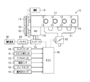
- FIG. 1 is a schematic configuration diagram of an engine control system
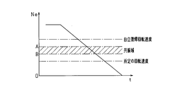
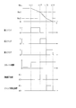
- FIG. 2 is a transition chart of the engine rotation speed during the rotation descent period.
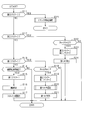
- FIG. 3 is a flowchart showing a process for stopping the engine speed
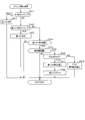
- FIG. 4 is a flowchart of the reverse torque setting process.
- FIG. 5 is a flowchart of the crank angle stop process.
- FIG. 6 is a timing chart showing a mode of processing for stopping the engine rotation speed.
- FIG. 7 is a timing chart showing an aspect of the crank angle stop process
- FIG. 8 is a timing chart showing an aspect of the crank angle stop process.
- the present embodiment embodies an engine control system mounted on a vehicle.
- an electronic control unit hereinafter referred to as ECU
- ECU electronice control unit
- the engine 11 is a four-cycle engine that is driven by combustion of fuel such as gasoline and repeatedly performs intake, compression, expansion, and exhaust strokes.
- the engine 11 has four cylinders (cylinders) 12, and pistons 13 are accommodated in the respective cylinders 12.
- the engine 11 is appropriately provided with a fuel injection valve (not shown), an ignition device (not shown), and the like.
- a four-cylinder engine is shown, but the number of cylinders in the engine may be any number.
- the engine 11 is not limited to a gasoline engine, and may be a diesel engine.
- the cylinder 12 is supplied with air from the intake section 20.
- the intake section 20 has an intake manifold 21, and a throttle valve 22 that adjusts the intake air amount is provided upstream of the intake manifold 21.
- the engine 11 is integrally provided with an MG (motor generator) 30.
- the MG 30 is a rotating electrical machine that is driven as an electric motor and a generator.
- the crankshaft (engine output shaft) 14 of the engine 11 is mechanically connected to the crank pulley 15, and the rotation shaft 31 of the MG 30 is mechanically connected to the MG pulley 32.
- the crank pulley 15 and the MG pulley 32 are drivingly connected by a belt 33.
- the MG 30 is connected to the battery 35 via an inverter 34 that is a power conversion circuit.
- inverter 34 When MG 30 is driven as an electric motor, electric power is supplied from battery 35 to MG 30 via inverter 34 in accordance with a command from ECU 50. As a result, the MG 30 is driven.
- the inverter 34 may be provided with another ECU that receives a command from the ECU 50 and controls the power conversion circuit of the inverter 34.
- the MG 30 functions as a generator, the power generated by the MG 30 is converted from alternating current to direct current by the inverter 34 and then charged to the battery 35.
- the battery 35 is connected to an electric load 36 such as a lamp or an audio device.
- an auxiliary device 16 such as a water pump, a fuel pump, and an air conditioner compressor is mounted on the vehicle 10 as an auxiliary device that is driven by the rotation of the crankshaft 14.
- the auxiliary device includes a device in which the coupling state with the crankshaft 14 is intermittently connected by the clutch means in addition to the auxiliary device 16 that is drivingly connected to the engine 11 by a belt or the like.
- the ECU 50 is an electronic control device including a microcomputer including a well-known CPU, ROM, RAM, and the like.
- the ECU 50 controls the opening degree of the throttle valve 22 based on the detection results of various sensors provided in the system.
- Various engine controls such as fuel injection control by the fuel injection valve are performed.
- the ECU 50 includes a crank angle sensor 51 for detecting the rotational position of the crankshaft 14 and the engine rotational speed Ne, an accelerator sensor 52 for detecting the accelerator operation amount (accelerator opening), and a vehicle speed sensor for detecting the vehicle speed. 53, a brake sensor 54 for detecting the operation amount of the brake pedal, an in-cylinder pressure sensor 55 for detecting the in-cylinder pressure in the cylinder, and a battery sensor 56 for detecting the battery state of the battery 35 are connected. These signals are sequentially input to the ECU 50.
- the crank angle sensor 51 includes an electromagnetic pickup type rotational position detecting means for outputting a rectangular detection signal (crank pulse signal) for each predetermined crank angle (for example, at a cycle of 10 ° CA).
- the engine speed Ne is calculated from the time required every time the crankshaft 14 rotates by 10 ° CA. Further, according to the detection result of the rotational position, the rotational position of the crankshaft 14 with respect to a predetermined reference position (for example, compression top dead center) is calculated, and the stroke determination of the engine 11 is performed.
- the battery sensor 56 detects a voltage between terminals of the battery 35, a charge / discharge current, and the like. Based on these detected values, the remaining battery capacity (SOC) of the battery 35 is calculated.
- the ECU 50 performs idling stop control of the engine 11.
- the idling stop control stops combustion of the engine 11 when a predetermined automatic stop condition is satisfied, and then restarts the engine 11 when a predetermined restart condition is satisfied.
- the automatic stop condition includes, for example, that the vehicle speed of the host vehicle is in the engine automatic stop speed range (for example, vehicle speed ⁇ 10 km / h) and the accelerator operation is released or the brake operation is performed. included.
- the restart condition includes, for example, that an accelerator operation is started and a brake operation is released. It is also possible to adopt a configuration in which the engine control function and the idling stop function are implemented by separate ECUs 50.
- FIG. 2 shows the transition of the engine rotation speed Ne during the rotation drop period until the combustion of the engine 11 is stopped and the engine rotation speed Ne becomes zero.
- the engine rotation speed Ne passes through a self-recovery return rotation speed, an engine resonance range, and a predetermined rotation speed set in advance (for example, about 200 rpm).
- the self-recovery return rotational speed is a lower limit of the rotational speed at which the engine can be restarted by restarting the fuel supply without cranking while the combustion of the engine 11 is stopped, and is set to about 500 rpm, for example. .
- the engine resonance region refers to the region of the engine speed at which resonance occurs, and is set to 300 to 400 rpm, for example.
- resonance is a phenomenon that is excited when the excitation frequency corresponding to the engine rotation speed matches the resonance frequency of a power plant such as an engine body or an automatic transmission. Due to this phenomenon, vibration increases in the resonance region of the engine. Thus, the vibration in the resonance region is one factor of unpleasant vibration that occurs when the engine stops.
- the resonance region of the engine is provided on the lower rotation side than the idle rotation speed and on the higher rotation side than the cranking rotation speed of the conventional starter so that vibration due to resonance does not occur as much as possible. Therefore, after the combustion of the engine is stopped, the engine rotation speed Ne passes through the resonance region in the rotation descent period until the engine rotation speed Ne reaches zero.
- This embodiment shows the engine control in the rotation descent period until the combustion of the engine 11 is stopped and the engine rotation speed Ne becomes zero.
- the rotation descent period is divided into three periods based on the engine speed Ne. That is, the period from when the combustion of the engine 11 stops until the engine rotational speed Ne reaches the upper limit value of the predetermined rotational speed region including the resonance region (specifically, the boundary value A on the high rotation side of the resonance region).
- the first period is the second period when the engine rotation speed Ne is in the predetermined rotation speed range, and the engine rotation speed Ne is the lower limit value of the predetermined rotation speed area (specifically, the boundary value on the low rotation side of the resonance area).
- the period from the passage of B) until the engine speed Ne becomes zero was defined as the third period.
- engine control is performed according to each period.
- the opening of the throttle valve 22 is set to an opening larger than the idle rotation state. As a result, the amount of air necessary for restarting the engine is secured.
- a rotation descent process for increasing the descent speed of the engine rotation speed Ne in a predetermined rotation speed range including the resonance range is performed.
- the time for passing through the resonance region can be shortened, and vibrations caused by the resonance region can be suppressed.
- reverse rotation side torque (reverse torque) is applied to the crankshaft 14 so that the piston 13 is stopped at the crank rotation position in the first half of the expansion stroke when the rotation of the crankshaft 14 is stopped.
- FIG. 3 is a flowchart showing a processing procedure for engine control, and this processing is repeatedly executed by the ECU 50 at a predetermined cycle (for example, 10 ms).
- the first flag, the second flag, and the third flag in the figure correspond to the first period, the second period, and the third period, respectively, and whether or not the engine speed Ne belongs to each period. It is a flag which shows. Each flag indicates that the engine speed Ne belongs to the period when “1”, and does not belong to the period when “0”. In the initial setting, both are set to “0”.
- step S11 it is determined whether or not the third flag is “1”.
- step S12 it is determined whether or not the second flag is “1”.
- step S13 it is determined whether or not the first flag is “1”. If step S11 to step S13 are negative in the initial state, the process proceeds to step S14 to determine whether or not the engine automatic stop condition is satisfied. And when step S14 is denied, this process is complete
- step S14 determines whether the engine automatic stop condition is satisfied. If it is determined in step S14 that the engine automatic stop condition is satisfied, the process proceeds to step S15, and "1" is set to the first flag. In the subsequent step S16, the combustion of the engine 11 is stopped, and the process proceeds to step S17.
- step S17 the opening of the throttle valve 22 is set to an opening larger than the opening in the idle rotation state (specifically, the opening is set to + 10% or more with respect to the opening in the idle rotation state, for example, This process is terminated.
- step S17 corresponds to a throttle control unit.
- step S18 in which it is determined whether or not the engine rotational speed Ne is equal to or lower than a predetermined rotational speed Ne1 that is an upper limit value of the predetermined rotational speed range.
- the boundary value A on the high rotation side of the resonance region is set as the predetermined rotation speed Ne1. That is, in step S18, it is determined whether or not the engine rotation speed Ne has reached the boundary value A on the high rotation side of the resonance region.
- step S18 If it is determined in step S18 that the engine rotational speed Ne is greater than the predetermined rotational speed Ne1, this process is terminated. On the other hand, if it is determined in step S18 that the engine rotational speed Ne is equal to or lower than the predetermined rotational speed Ne1, that is, if the engine rotational speed Ne has shifted to the resonance range, the process proceeds to step S19, and the second flag is set to “1”. At the same time, the first flag is reset to “0”.
- step S20 first, reverse torque is set.
- the MG30 has a power generation function as a generator and a power running function as an electric motor, and applying reverse torque is executed using each function.
- the power running drive has a larger reverse torque than the regenerative power generation, and the regenerative power generation is superior in terms of fuel consumption compared to the power running drive. Therefore, it is desirable to use each function properly according to the driving state. In such a case, which function is used is determined based on various parameters.
- the MG 30 depends on the amount of power consumed by the electrical load 36 connected to the battery 35, the state of the remaining capacity of the battery 35, the amount of torque required to apply reverse torque, and the load due to the operation of the auxiliary machine 16. The regenerative power generation and power running drive are selected.
- Fig. 4 shows a flowchart of reverse torque setting.
- step S31 it is determined whether the power consumption of the electrical load 36 is equal to or greater than a predetermined value.
- the electric load 36 include lamps and an electric pump. More specifically, it is determined whether or not the brake pedal is depressed. When the brake pedal is depressed, the brake lamp is lit, and the power consumption is increased. If it is determined in step S31 that the brake pedal is depressed, the process proceeds to step S32, and it is determined to apply reverse torque by regenerative power generation. In this case, since the amount of power consumed by the electric load 36 is large, vibration can be suppressed while reducing the burden on the battery 35 by using regenerative power generation.
- step S31 determines whether or not the SOC of the battery 35 is greater than or equal to the threshold Th1.
- step S33 determines whether or not the SOC of the battery 35 is greater than or equal to the threshold Th1.
- the threshold Th1 may be changed as appropriate. For example, when the threshold Th1 is equal to or greater than the threshold Th1, it may be a value that can be determined to be a fully charged state.
- an estimation method based on an open circuit voltage (OCV) and a calculation method based on current integration are used.
- OCV open circuit voltage
- the SOC is estimated using the acquired value and a map representing the correspondence relationship between the open-circuit voltage and the SOC, and the charge / discharge current flowing through the battery 35 is acquired.
- the SOC is calculated by calculating the obtained value.
- reverse torque by power running drive it is good also as a setting which makes reverse torque large, so that electric remaining amount is large. In this case, it is considered that the passing time through the resonance region can be further shortened and the vibration suppressing effect is enhanced.
- step S33 when step S33 is denied, it progresses to step S34 and a function is selected according to the request
- step S34 the process proceeds to step S35, and a function is selected according to the load of the auxiliary machine 16. For example, it is determined whether or not the load due to the operation of the auxiliary machine 16 is greater than or equal to the threshold Th3. When it determines with it being more than threshold value Th3 by step S35, it progresses to step S32 and determines providing reverse torque by regenerative power generation. In such a case, the power consumption of the electric load 36 is less than a predetermined value (step S31: NO), but regenerative power generation is selected in view of other parameters indicating the driving state of the vehicle.
- step S35 when step S35 is denied, it progresses to step S36 and determines giving reverse torque by power running drive. As described above, after regenerative power generation or power running drive is determined based on the parameters, the process proceeds to step S21 in FIG. 3 to apply reverse torque.
- step S31 when step S31 is NO, it may be configured to proceed to step S36 without selecting the determination of step S33 to step S35 and select power running drive. That is, when the electric power consumption of the electric load 36 is less than a predetermined value, a configuration in which reverse torque is applied by power running drive may be used.
- the application of reverse torque by power running drive corresponds to the first rotation descent process
- the application of reverse torque by regenerative power generation corresponds to the second rotation descent process
- step S12 of FIG. 3 determines whether the second flag is “1”
- the process proceeds to step S22, and whether the engine rotational speed Ne is smaller than the predetermined rotational speed Ne2 that is the lower limit value of the predetermined rotational speed range. Determine whether or not.
- the boundary value B on the low rotation side of the resonance region is set as the predetermined rotation speed Ne2. That is, in step S22, it is determined whether or not the engine rotation speed Ne has passed the boundary value B on the low rotation side of the resonance region.
- step S22 If it is determined in step S22 that the engine rotational speed Ne is smaller than the predetermined rotational speed Ne2, that is, if the engine rotational speed Ne has shifted to the third period, the process proceeds to step S23, and the third flag is set to “1”. At the same time, the second flag is reset to “0”. In subsequent step S24, the reverse torque applied in step S21 is stopped. On the other hand, if it is determined in step S22 that the engine rotational speed Ne is equal to or higher than the predetermined rotational speed Ne2, the present process is terminated.
- step S18 and step S22 is corresponded to the resonance area determination part which determines passing through the resonance area of an engine.
- the process of step S20 and step S21 is equivalent to a rotation descent control part.
- step S11 determines whether the third flag is “1”
- the process proceeds to step S25 to execute the subroutine shown in FIG. That is, when the engine speed Ne shifts to the third period, the crank angle stop process for suppressing the reverse rotation of the engine is performed.
- reverse torque is applied at a predetermined timing based on the engine speed so that the piston 13 is stopped at the first half of the expansion stroke, that is, the piston 13 of the next combustion cylinder is stopped at the first half of the compression stroke.
- a backup process for applying a torque (forward torque) on the forward rotation side to the engine output shaft is also executed. That is, in the crank angle stop process, control is performed so that the piston 13 does not stop at the latter half of the compression stroke, that is, the piston 13 does not stop at the position where the compression reaction force is generated.
- step S41 of FIG. 5 it is first determined whether or not it is time to apply a positive torque to the engine output shaft. This step is affirmed when it is determined that the backup process is to be executed, and step S41 is denied in the initial setting.
- step S42 it is determined whether or not it is time to apply a reverse torque to the engine output shaft. In the present embodiment, for example, when the engine rotation speed Ne when the piston 13 is positioned at the compression TDC is equal to or lower than the predetermined rotation speed Ne3, it is determined that it is the timing to apply the reverse torque. If it is determined that it is time to apply reverse torque, the process proceeds to step S43, where reverse torque is applied to the engine output shaft, and this process ends.
- the predetermined rotational speed Ne3 is determined to stop rotation of the engine output shaft by applying reverse torque from the timing when the piston is positioned at the compression TDC until the piston passes the first half of the expansion stroke. Rotation speed.
- the predetermined rotational speed Ne3 is set to a value smaller than the predetermined rotational speed Ne2 that is the lower limit value of the predetermined rotational speed range.
- step S42 determines whether or not the timing to apply the reverse torque.
- step S44 determines whether or not the reverse torque is applied.
- step S44 determines whether the reverse torque is applied
- the process proceeds to step S45, where the crank rotational position detected by the crank angle sensor 51 is set to a predetermined angle (for example, ATDC 70 ° CA). It is determined whether or not. If it is determined that the rotational position is the predetermined angle, the process proceeds to step S46, and it is determined whether or not the engine rotational speed Ne is equal to or lower than the predetermined rotational speed Ne4. On the other hand, when step S45 is denied, this process is complete
- a predetermined angle for example, ATDC 70 ° CA
- step S46 If it is determined in step S46 that the engine rotational speed Ne is equal to or lower than the predetermined rotational speed Ne4, that is, if it is determined that the piston 13 stops in the first half of the expansion stroke, the process proceeds to step S47, and is given in step S43. Instructs to stop reverse torque. As a result, the reverse torque applied to the engine output shaft is stopped. Then, it progresses to step S48, a 3rd flag is reset to "0", and this process is complete
- step S45 and step S46 correspond to a stop determination unit.
- the predetermined rotational speed Ne4 at the predetermined angle can be arbitrarily changed, and can be determined whether or not the piston 13 actually stops at the crank rotational position until the first half of the expansion stroke after applying the reverse torque in step S43. If it is.
- step S46 determines whether the engine rotational speed Ne is greater than the predetermined rotational speed Ne4 or not stop at the first half of the expansion stroke. That is, it is determined that the backup process is executed.
- this process is executed and the crank rotational position is at a predetermined rotational angle (for example, ATDC 90 ° CA), it is determined that it is time to apply a positive torque to the engine output shaft (step) S41: YES).
- step S41 If step S41 is affirmed, the process proceeds to step S50, a positive torque is applied, and the process is terminated. Thereafter, the process proceeds to step S42 again, and the crank angle stop process is executed until the third flag is finally reset to “0”.
- the first flag is set to “1”.
- the opening degree of the throttle valve 22 is controlled to be larger than the opening degree in the idle state.
- the second flag is set to “1” and at the same time the first flag is reset to “0”.
- a reverse torque is applied to the engine output shaft as a rotation descent process.
- the third flag is set to “1” and at the same time the second flag is reset to “0”.
- the rotation descent process is stopped, and the crank angle stop process is executed in the subsequent third period.
- the timing t14 the engine rotational speed Ne becomes zero.
- FIGS. 7 shows a case where step S46 is affirmed and only reverse torque is applied in the third period
- FIG. 8 shows that step S46 is negated and positive torque is applied in addition to reverse torque in the third period. Shows the case.
- changes in the in-cylinder pressure of each cylinder are shown. The in-cylinder pressure increases as the piston 13 approaches the compression TDC, and becomes maximum at the compression TDC. Further, the maximum value of the in-cylinder pressure decreases as the engine speed Ne decreases. Note that the firing order of each cylinder is # 1 ⁇ # 2 ⁇ # 3 ⁇ # 4 for convenience of explanation.
- a four-cylinder engine is shown as a multi-cylinder engine.
- the piston 13 of one cylinder stops at the position of the first half period of the expansion stroke
- the piston 13 of the other cylinder does not stop at the position of the second half period of the compression stroke, that is, the position where the compression reaction force is generated.
- the opening of the throttle valve 22 is set to an opening larger than the opening in the idle rotation state, which is necessary when the engine is restarted. A sufficient amount of air can be secured. Further, by applying the reverse torque using the MG 30 so that the decrease rate of the engine rotation speed is increased in the resonance region, it is possible to shorten the time for passing through the resonance region. In this case, in a state where the throttle opening is large, there is a concern about an increase in vibration in the resonance region, but an increase in vibration can be suppressed by reducing the passage time of the resonance region. As a result, in a vehicle having an idling stop function, it is possible to ensure startability at the time of restart while suppressing generation of vibration at the time of automatic engine stop.
- the throttle valve 22 is configured to have an opening larger than the opening in the idle rotation state. Therefore, even when the restart condition is satisfied immediately after the combustion is stopped, a sufficient amount of air can be secured and the startability at the time of restart is improved.
- a reverse torque is applied using MG30.
- the regenerative power generation and the power running drive can be selected.
- the power running drive has a larger reverse torque than the regenerative power generation, and the regenerative power generation is superior in terms of fuel consumption compared to the power running drive.
- the regenerative power generation and the power running drive can be selected according to the power consumption of the electric load 36 connected to the battery 35.
- the battery 35 is burdened and reverse torque is applied by regenerative power generation. Thereby, it is possible to suppress vibration while keeping the power state of the battery 35 stable.
- the regenerative power generation and the power running driving can be selected based on the remaining electric power of the battery 35.
- the threshold value Th1 when the remaining amount of electricity is equal to or greater than the threshold value Th1, reverse torque is applied by powering drive.
- the remaining amount of electricity in the battery 35 is large, there is a concern about overcharging of the battery 35 by causing the rotating electric machine to generate regenerative power.
- by applying the reverse torque by powering drive it is possible to suppress vibration caused by the resonance region without damaging the battery 35.
- the MG 30 is used to apply reverse torque from the compression top dead center.
- the piston 13 can be stopped at the first half of the expansion stroke by applying reverse torque. Thereby, the vibration accompanying it can be reduced by suppressing generation
- the engine 11 is determined to be the previous compression top dead center based on the engine rotation speed at the compression top dead center being equal to or less than a predetermined value.
- the predetermined value is a value that is determined by stopping the piston 13 at the first half of the expansion stroke by applying reverse torque. Therefore, the piston 13 can be stopped at a desired position, and the vibration accompanying the reverse rotation of the engine can be reduced.
- a stop determination unit that determines whether or not the piston 13 actually stops at a desired position is provided, and when it is determined to stop at the desired position, the reverse torque application is stopped. It was. In this case, when the rotation of the engine stops at the first half of the expansion stroke, the application of reverse torque is released. Thereby, reverse rotation of the engine due to reverse torque can be prevented.
- backup processing was provided for stop control in the third period. That is, when the stop determination unit determines that the piston 13 does not stop at a desired position, a positive torque is once applied so that the piston 13 can get over the next compression TDC. Then, when the compression TDC is reached, a reverse torque is applied again to stop the piston at the first half of the expansion stroke. Thereby, the piston 13 can be more reliably stopped at the first half of the expansion stroke, and the vibration suppressing effect can be enhanced.
- the reverse torque is applied in the resonance region using the MG 30, and the reverse torque by the crank stop process is applied in the third period, or Forward / reverse torque was applied.
- the vibration accompanying the reverse rotation of the engine can be suppressed.
- the adverse effect of the vibration in the resonance region on the reverse rotation vibration is reduced.
- the vibration generated between the stop of the combustion of the engine 11 and the stop of the rotation of the engine 11 is synergistically. Can be suppressed.
- the MG30 is used as an auxiliary device to apply reverse torque, but any auxiliary device that can apply reverse torque to the engine output shaft may be used.
- the auxiliary equipment include auxiliary equipment 16 such as a water pump and a fuel pump. In this case, even in a vehicle not equipped with the MG 30, reverse torque can be applied using a device that is normally provided in the vehicle. For this reason, there is no need to provide a new device separately, which is economical.
- the reverse torque is applied with the predetermined rotation speed range as the resonance range. That is, the upper limit value of the predetermined rotation speed range is set as the boundary value A on the high rotation side of the resonance range, and the lower limit value of the predetermined rotation speed range is set as the boundary value B on the low rotation side of the resonance range.
- the predetermined rotational speed region may be configured so as to include the resonance region.
- the predetermined rotational speed region may be determined by setting the predetermined rotational speed higher than the resonance region as the upper limit value.
- step S18 of FIG. 3 it is determined whether or not the engine rotational speed Ne is equal to or lower than a predetermined rotational speed Ne1 set higher than the boundary value A of the resonance region, and step S18 is YES. If so, the application of reverse torque is started.
- the reverse torque is applied before reaching the resonance range, thereby improving the response to the descending speed due to the reverse torque near the boundary value A in the resonance range. Can do. As a result, the passage time of the resonance region is further shortened, and the vibration suppressing effect is enhanced.
- the predetermined rotational speed range may be determined with the self-recovery return rotational speed higher than the resonance area as the upper limit value.
- step S18 of FIG. 3 it is determined whether or not the engine rotational speed Ne is equal to or lower than the predetermined rotational speed Ne1 set to the self-recovery return rotational speed. If step S18 is YES, reverse torque is applied. Start.
- the engine rotational speed Ne1 exceeds the predetermined rotation speed Ne1 at the beginning when the engine starts to stop combustion, the decrease speed of the engine rotation speed is not increased, and the possibility of the engine self-recovery is possible. Can be expected. As a result, the power consumption required for restart can be reduced, the response to the descent speed in the resonance region can be improved, and the vibration suppression effect can be enhanced.
- the predetermined rotational speed range may be determined by setting a predetermined rotational speed set in advance on the lower rotation side than the resonance range as a lower limit value.
- step S22 of FIG. 3 it is determined whether or not the engine rotational speed Ne is lower than a predetermined rotational speed Ne2, and if step S22 is YES, the application of reverse torque is stopped.
- step S22 it is possible to expect the possibility of restarting the engine due to cranking without increasing the decrease rate of the engine rotation speed while the engine rotation speed is between a predetermined rotation speed set in advance and zero. .
- restartability can be ensured while suppressing vibration in the resonance region.
- the predetermined rotational speed range may be set by combining the setting of the upper limit value and the lower limit value of the predetermined rotational speed range described above. For example, it is possible to set the upper limit value of the predetermined rotation speed range to a self-recovery return rotation speed higher than the resonance range and the lower limit value to a predetermined rotation speed set in advance on the lower rotation side than the resonance range. In such a case, it is possible to pass through the rotational speed region where the engine cannot be restarted at an early stage by means of fuel supply or cranking. On the other hand, in the region where the engine can be restarted, the decrease speed of the engine speed is not increased. As a result, restartability can be ensured while suppressing vibration in the resonance region.
- the power consumption of the electrical load 36 connected to the battery 35 the state of the remaining capacity of the battery 35, the required torque amount required for the reverse torque application, and the auxiliary machine 16
- the regenerative power generation and the power running drive of the MG 30 are selected according to the load caused by the operation of the above, but the configuration may be selected according to other parameters. Other parameters include the rotational speed of the MG 30 and the like.
- priority may be set between the above parameters. For example, the determination based on the driving state of the electric load 36 may be given the highest priority, followed by the state of the remaining capacity of the battery 35, the required torque amount necessary for applying reverse torque, and the load due to the operation of the auxiliary machine 16.
- the SOC of the battery 35 is used as the state of the remaining capacity of the battery 35.
- the present invention is not limited to this.
- the voltage between the terminals of the battery 35 may be used.
- the reverse torque is applied from the timing t31 to the timing t33 in FIG. 8, but the reverse torque is stopped at the time of the stop determination at the timing t32. Good.
- a positive torque is applied from the timing t33 to the timing t34 (timing when the second cylinder (# 2) reaches the compression TDC).
- the period for applying the positive torque is not limited to this, and any structure may be used as long as the positive torque is applied so that the piston (here, the second cylinder (# 2)) can overcome the compression TDC.
- the configuration may be such that positive torque application is stopped.
- the magnitude of the reverse torque applied in the crank angle stop process may be determined in advance as the amount of torque required to stop the piston 13 at the first half of the expansion stroke. Also, means for predicting the stop position of the piston 13 every moment when the rotation of the engine stops is provided, and even if reverse torque is applied while performing feedback control for adjusting the torque amount based on the predicted stop position. Good.
- the magnitudes of the reverse torque and the positive torque applied in the crank angle stop process may be appropriately changed, and may be the same torque amount or different torque amounts. Further, the magnitudes of the first reverse torque and the second reverse torque when the backup process is performed may be appropriately changed. For example, the second reverse torque may be made larger than the first reverse torque, and according to this configuration, it is considered that the piston can be more reliably stopped at a desired position.
- the crank angle position at which the predetermined rotation speed Ne3 is set is not limited to the compression TDC, and the engine rotation speed Ne at other crank angle positions may be set as a threshold value for determination.
- the application of reverse torque may be started from the crank angle position at which the threshold is set.
- the predetermined rotation speed Ne3 is provided as a threshold value for the engine rotation speed as the determination of the timing for applying the reverse torque.
- the present invention is not limited to this method.
- a method may be used in which the timing is determined from the decrease in the engine rotational speed Ne.
- the ECU 50 calculates the rotational speed drop amount ⁇ Ne from the engine rotational speed Ne for each compression TDC, and estimates the compression TDC (i) that is predicted to be less than zero.
- the timing at which the compression TDC (i ⁇ 1) immediately before the compression TDC (i) is reached can be set as the reverse torque application timing.
- the above-described control during the rotation descent period until the engine rotation speed becomes zero is not limited to the automatic engine stop, but may be performed in the case of a stop by the driver's ignition switch operation. Moreover, the case of the stop in the vehicle which does not have an idling stop function may be sufficient.
Abstract
After the combustion of an engine (11) has stopped and during a speed reduction period when the engine speed reduces to zero, an ECU (50) opens a throttle valve (22) to a greater degree than during idle rotation of the engine (11). In addition, the ECU (50) determines, during the speed reduction period, whether or not the engine speed is in a prescribed rotation speed range including at least a resonance range for the engine (11) and, if a determination is made that the engine speed is within the prescribed rotation speed range, implements speed reduction whereby the speed of reduction in the engine speed is temporarily increased.
Description
本出願は、2016年5月10日に出願された日本出願番号2016-094757号に基づくもので、ここにその記載内容を援用する。
This application is based on Japanese Patent Application No. 2016-094757 filed on May 10, 2016, the contents of which are incorporated herein by reference.
本開示は、エンジン停止始動制御装置に関するものである。
The present disclosure relates to an engine stop / start control device.
従来、所定の自動停止条件が成立するとエンジンを自動停止させるとともに、その後、所定の再始動条件が成立するとエンジンを再始動させる、いわゆるアイドリングストップ制御を実施する技術が知られている。
Conventionally, there has been known a technique for performing so-called idling stop control in which an engine is automatically stopped when a predetermined automatic stop condition is satisfied, and thereafter, the engine is restarted when a predetermined restart condition is satisfied.
エンジンの自動停止を行う際には、スロットルバルブの開度が所定開度より小さくされ、気筒への空気供給が制限される。しかし、かかる場合には、エンジン再始動時において、燃焼に十分な空気量が確保できず、再始動の悪化を招くこととなる。
When the engine is automatically stopped, the throttle valve opening is made smaller than the predetermined opening, and the air supply to the cylinder is restricted. However, in such a case, at the time of restarting the engine, an air amount sufficient for combustion cannot be secured, resulting in deterioration of restart.
特許文献1に記載の技術では、エンジンの自動停止を行う際にスロットルバルブの開度を所定開度より小さくし、エンジン回転速度が所定値以下となったら閉じていたスロットルバルブを所定開度よりも一旦大きく開き、その後再び閉じるように制御している。これにより、エンジンの再始動時に最低限必要な空気量を確保し、再始動時のもたつき等の緩和を図っている。
In the technique described in Patent Document 1, when the engine is automatically stopped, the opening of the throttle valve is made smaller than a predetermined opening, and the closed throttle valve is moved from the predetermined opening when the engine rotational speed becomes a predetermined value or less. Is also controlled to open once and then close again. As a result, the minimum amount of air required at the time of restarting the engine is ensured, and slackening or the like at the time of restart is reduced.
しかしながら、特許文献1ではアイドリングストップ実施時において、エンジン出力軸の回転が停止するまでの間にスロットルバルブを開いて空気を導入すると、気筒内の圧縮反力が増し、その結果振動が増加する懸念がある。加えて、スロットルバルブを閉じる期間が存在することから、やはり再始動時に空気量が不足するおそれがある。
However, in Patent Document 1, when idling stop is performed, if the throttle valve is opened and air is introduced before the rotation of the engine output shaft stops, the compression reaction force in the cylinder increases, and as a result, vibration may increase. There is. In addition, since there is a period during which the throttle valve is closed, there is a possibility that the air amount is insufficient at the time of restart.
本開示は、アイドリングストップ機能を備えた車両において、エンジン自動停止時における振動の発生を抑制しつつ、再始動時の始動性を確保することができるエンジン制御装置を提供することを主目的とする。
A main object of the present disclosure is to provide an engine control device capable of ensuring startability at restart while suppressing generation of vibration at the time of automatic engine stop in a vehicle having an idling stop function. .
第1の開示は、吸気部にスロットルバルブが設けられたエンジンに適用され、所定の自動停止条件の成立に伴い前記エンジンを自動停止させ、その後所定の再始動条件の成立に伴い前記エンジンを再始動させるエンジン停止始動制御装置であって、前記エンジンの燃焼が停止された後、エンジン回転速度がゼロまで降下する際の回転降下期間において、前記スロットルバルブの開度を、前記エンジンのアイドル回転状態での開度よりも大きい開度とするスロットル制御部と、前記回転降下期間において、エンジン回転速度が少なくとも前記エンジンの共振域を含む所定回転速度域にあることを判定する共振域判定部と、エンジン回転速度が前記所定回転速度域にあると判定された場合に、一時的にエンジン回転速度の降下速度を大きくする回転降下処理を実施する回転降下制御部と、を備える。
The first disclosure is applied to an engine in which a throttle valve is provided in an intake portion, and automatically stops the engine when a predetermined automatic stop condition is satisfied, and then restarts the engine when a predetermined restart condition is satisfied. An engine stop / start control device for starting the engine, wherein after the combustion of the engine is stopped, the opening of the throttle valve is set in an idle rotation state of the engine during a rotation drop period when the engine rotation speed drops to zero. A throttle control unit that has an opening larger than the opening in the engine, and a resonance region determination unit that determines that the engine rotation speed is in a predetermined rotation speed region including at least the resonance region of the engine in the rotation descent period; When it is determined that the engine rotation speed is within the predetermined rotation speed range, the decrease speed of the engine rotation speed is temporarily increased. Comprising a rotating drop control unit to carry out the rolling lowering process, the.
上記構成によれば、エンジンの燃焼が停止された後にスロットルバルブの開度を大きくすることで、エンジンの再始動時に必要な空気量を十分に確保することができる。また、エンジン回転速度の降下速度が共振域を含む所定回転速度域で大きくなるようにすることで、共振域を通過する時間を短縮することができる。この場合、スロットル開度が大きい状態では、共振域において振動増大が懸念されるが、共振域の通過時間が短縮されることで、振動増大を抑制できる。これにより、アイドリングストップ機能を備えた車両において、エンジン自動停止時における振動の発生を抑制しつつ、再始動時の始動性を確保することができる。
According to the above configuration, the amount of air necessary for restarting the engine can be sufficiently secured by increasing the opening of the throttle valve after the combustion of the engine is stopped. In addition, the time for passing through the resonance region can be shortened by increasing the decrease rate of the engine rotation speed in a predetermined rotation speed region including the resonance region. In this case, in a state where the throttle opening is large, there is a concern about an increase in vibration in the resonance region, but an increase in vibration can be suppressed by reducing the passage time of the resonance region. As a result, in a vehicle having an idling stop function, it is possible to ensure startability at the time of restart while suppressing generation of vibration at the time of automatic engine stop.
第2の開示は、エンジン出力軸に対して逆回転側のトルクである逆トルクを付与可能な補機装置を備えるシステムに適用され、前記回転降下制御部は、前記回転降下処理として、前記補機装置により前記エンジン出力軸に逆トルクを付与する。
The second disclosure is applied to a system including an auxiliary device capable of applying a reverse torque that is a reverse rotation side torque with respect to an engine output shaft, and the rotation descent control unit performs the auxiliary descent process as the auxiliary descent process. A reverse torque is applied to the engine output shaft by a mechanical device.
上記構成では、補機装置により逆トルクを付与することで、車両に通常備わっている装置を回転降下処理に用いることができる。そのため、別途新たな装置を設ける必要がなく経済的である。
In the above configuration, by applying reverse torque by the auxiliary device, a device normally provided in the vehicle can be used for the rotation descent process. For this reason, there is no need to provide a new device separately, which is economical.
第3の開示は、前記補機装置は、前記エンジン出力軸に駆動連結され、発電及び力行駆動の各機能を有する回転電機である。
According to a third disclosure, the auxiliary device is a rotating electrical machine that is drivingly connected to the engine output shaft and has functions of power generation and power running.
上記構成では、補機装置として回転電機を用いることで、より大きな逆トルクを付与することが可能となる。これにより、共振域の通過時間が一層短縮され、振動の抑制効果が高まる。
In the above configuration, a larger reverse torque can be applied by using a rotating electrical machine as an auxiliary device. Thereby, the passage time of the resonance region is further shortened, and the vibration suppressing effect is enhanced.
第4の開示は、前記共振域よりも高回転側の所定回転速度を上限値として、前記所定回転速度域が定められており、前記回転降下制御部は、前記共振域判定部によりエンジン回転速度が前記上限値以下であると判定された場合に、前記回転降下処理を開始する。
According to a fourth disclosure, the predetermined rotation speed range is determined with an upper limit value being a predetermined rotation speed higher than the resonance area, and the rotation lowering control unit is configured so that the engine rotation speed is determined by the resonance area determination unit. Is determined to be less than or equal to the upper limit value, the rotation descent process is started.
上記構成では、エンジン回転速度が、共振域よりも高回転側の所定回転速度以下であると判定された場合に、回転降下処理を開始する構成とした。かかる場合、エンジン回転速度が共振域に到達する以前から回転降下処理を開始することで、共振域の境界値付近での降下速度に対するレスポンスを向上させることができる。その結果、共振域の通過時間が一層短縮され、振動の抑制効果が高まる。
In the above configuration, the rotation descent process is started when it is determined that the engine rotation speed is equal to or lower than the predetermined rotation speed higher than the resonance range. In such a case, the response to the descent speed near the boundary value of the resonance area can be improved by starting the rotation descent process before the engine rotation speed reaches the resonance area. As a result, the passage time of the resonance region is further shortened, and the vibration suppressing effect is enhanced.
第5の開示は、前記エンジンの燃焼停止後に前記エンジンの自立復帰が可能なエンジン回転速度として自立復帰回転速度が定められており、前記共振域よりも高回転側の前記エンジンの自立復帰回転速度を上限値として、前記所定回転速度域が定められており、前記回転降下制御部は、前記共振域判定部によりエンジン回転速度が前記上限値以下であると判定された場合に、前記回転降下処理を開始する。
According to a fifth disclosure, a self-recovery rotation speed is determined as an engine rotation speed at which the engine can be self-recovered after combustion of the engine is stopped, and the self-recovery rotation speed of the engine at a higher rotation side than the resonance range. Is set as the upper limit value, and the predetermined rotation speed range is determined, and the rotation drop control unit determines that the rotation drop process is performed when the resonance range determination unit determines that the engine rotation speed is equal to or lower than the upper limit value. To start.
上記構成では、エンジン回転速度が、共振域よりも高回転側の自立復帰回転速度以下であると判定された場合に、回転降下処理を開始する構成とした。かかる場合、エンジンの燃焼停止に伴いエンジン回転速度が降下し始める当初においては、エンジン回転速度の降下速度を大きくせず、エンジンの自立復帰の可能性を見込むことができる。これにより、再始動に必要な消費電力を削減しつつ、共振域での降下速度に対するレスポンスを向上させ、振動の抑制効果を高めることができる。
In the above configuration, the rotation descent process is started when it is determined that the engine rotation speed is equal to or lower than the self-recovery return rotation speed higher than the resonance range. In such a case, at the beginning of the engine rotation speed starting to decrease with the combustion stop of the engine, it is possible to expect the possibility of the engine self-recovery without increasing the engine rotation speed decrease speed. Thereby, while reducing the power consumption required for restart, the response to the descent speed in the resonance region can be improved, and the vibration suppressing effect can be enhanced.
第6の開示は、前記共振域よりも低回転側の予め設定した所定の回転速度を下限値として、前記所定回転速度域が定められており、前記回転降下制御部は、前記共振域判定部によりエンジン回転速度が前記下限値よりも小さいと判定された場合に、前記回転降下処理を停止する。
According to a sixth disclosure, the predetermined rotation speed range is determined with a predetermined rotation speed set on a lower rotation side than the resonance area as a lower limit value, and the rotation descent control unit is configured to detect the resonance range determination unit. When it is determined that the engine speed is smaller than the lower limit, the rotation descent process is stopped.
上記構成では、エンジン回転速度が、共振域よりも低回転側の予め設定した所定の回転速度よりも小さいと判定された場合に、回転降下処理を停止する構成とした。かかる場合、エンジン回転速度が予め設定した所定の回転速度からゼロまでの間は、エンジン回転速度の降下速度を大きくせず、クランキングによるエンジンの再始動の可能性を見込むことができる。その結果、共振域における振動を抑制しつつ、再始動の始動性を確保することができる。
In the above configuration, the rotation descent process is stopped when it is determined that the engine rotation speed is lower than a predetermined rotation speed set on the lower rotation side than the resonance range. In such a case, when the engine rotation speed is between a predetermined rotation speed set in advance and zero, the decrease speed of the engine rotation speed is not increased, and the possibility of engine restart due to cranking can be expected. As a result, restartability can be ensured while suppressing vibration in the resonance region.
第7の開示は、前記スロットル制御部は、自動停止条件の成立に伴い前記エンジンの燃焼を停止させた時点で、前記スロットルバルブの開度を前記アイドル回転状態での開度よりも大きい開度とする。
According to a seventh disclosure, when the throttle control unit stops combustion of the engine in response to establishment of an automatic stop condition, an opening degree of the throttle valve is larger than an opening degree in the idle rotation state. And
上記構成では、エンジンの燃焼を停止させた時点でスロットルバルブを大きく開くことで、燃焼が停止した直後に再始動条件が成立する場合でも、十分な空気量を確保でき、再始動時の始動性が良好となる。
In the above configuration, the throttle valve is greatly opened when the combustion of the engine is stopped, so that a sufficient amount of air can be secured even when the restart condition is satisfied immediately after the combustion stops, and the startability at the time of restart Becomes better.
本開示についての上記目的およびその他の目的、特徴や利点は、添付の図面を参照しながら下記の詳細な記述により、より明確になる。その図面は、
図1は、エンジン制御システムの概略構成図であり、
図2は、回転降下期間でのエンジン回転速度の推移チャートであり、
図3は、エンジン回転速度を停止する処理を示すフローチャートであり、
図4は、逆トルク設定の処理のフローチャートであり、
図5は、クランク角停止処理のフローチャートであり、
図6は、エンジン回転速度を停止する処理の態様を示すタイミングチャートであり、
図7は、クランク角停止処理の態様を示すタイミングチャートであり、
図8は、クランク角停止処理の態様を示すタイミングチャートである。
The above and other objects, features and advantages of the present disclosure will become more apparent from the following detailed description with reference to the accompanying drawings. The drawing
FIG. 1 is a schematic configuration diagram of an engine control system, FIG. 2 is a transition chart of the engine rotation speed during the rotation descent period. FIG. 3 is a flowchart showing a process for stopping the engine speed, FIG. 4 is a flowchart of the reverse torque setting process. FIG. 5 is a flowchart of the crank angle stop process. FIG. 6 is a timing chart showing a mode of processing for stopping the engine rotation speed. FIG. 7 is a timing chart showing an aspect of the crank angle stop process, FIG. 8 is a timing chart showing an aspect of the crank angle stop process.
以下、本開示を具体化した実施形態を図面に基づいて説明する。本実施形態は、車両に搭載されたエンジンの制御システムを具体化している。当該制御システムでは、電子制御ユニット(以下、ECUという)を中枢としてエンジンの運転状態等を制御する。本システムの全体概略図を図1に示す。
Hereinafter, embodiments embodying the present disclosure will be described with reference to the drawings. The present embodiment embodies an engine control system mounted on a vehicle. In this control system, an electronic control unit (hereinafter referred to as ECU) is used as a center to control the operating state of the engine. An overall schematic diagram of this system is shown in FIG.
図1に示す車両10において、エンジン11は、ガソリン等の燃料の燃焼によって駆動され、吸気、圧縮、膨張及び排気の各行程を繰り返し実施する4サイクルエンジンである。エンジン11は、4つのシリンダ(気筒)12を有し、各シリンダ12にはピストン13がそれぞれ収容されている。また、エンジン11は、燃料噴射弁(図示せず)や点火装置(図示せず)等を適宜備えている。なお、本実施形態では、4気筒のエンジンを示しているが、エンジンの気筒数はいくつであってもよい。また、エンジン11はガソリンエンジンに限定されず、ディーゼルエンジンであってもよい。
In the vehicle 10 shown in FIG. 1, the engine 11 is a four-cycle engine that is driven by combustion of fuel such as gasoline and repeatedly performs intake, compression, expansion, and exhaust strokes. The engine 11 has four cylinders (cylinders) 12, and pistons 13 are accommodated in the respective cylinders 12. The engine 11 is appropriately provided with a fuel injection valve (not shown), an ignition device (not shown), and the like. In the present embodiment, a four-cylinder engine is shown, but the number of cylinders in the engine may be any number. The engine 11 is not limited to a gasoline engine, and may be a diesel engine.
シリンダ12には、吸気部20から空気が供給される。吸気部20は、吸気マニホールド21を有し、吸気マニホールド21の上流には、吸入空気量を調整するスロットルバルブ22が設けられている。
The cylinder 12 is supplied with air from the intake section 20. The intake section 20 has an intake manifold 21, and a throttle valve 22 that adjusts the intake air amount is provided upstream of the intake manifold 21.
エンジン11には、MG(モータジェネレータ)30が一体に設けられている。MG30は、電動機及び発電機として駆動する回転電機である。エンジン11のクランク軸(エンジン出力軸)14は、クランクプーリ15に機械的に接続され、MG30の回転軸31は、MGプーリ32に機械的に接続されている。そして、クランクプーリ15とMGプーリ32とは、ベルト33により駆動連結されている。エンジン始動時には、MG30の回転によりエンジン11に初期回転(クランキング回転)が付与される。なお、別途スタータモータを設け、スタータモータの回転によりエンジン11に初期回転を付与する構成としてもよい。
The engine 11 is integrally provided with an MG (motor generator) 30. The MG 30 is a rotating electrical machine that is driven as an electric motor and a generator. The crankshaft (engine output shaft) 14 of the engine 11 is mechanically connected to the crank pulley 15, and the rotation shaft 31 of the MG 30 is mechanically connected to the MG pulley 32. The crank pulley 15 and the MG pulley 32 are drivingly connected by a belt 33. When the engine is started, an initial rotation (cranking rotation) is applied to the engine 11 by the rotation of the MG 30. In addition, it is good also as a structure which provides a starter motor separately and provides initial rotation to the engine 11 by rotation of a starter motor.
また、MG30は、電力変換回路であるインバータ34を介してバッテリ35に接続されている。MG30が電動機として駆動する場合には、ECU50の指令により、電力がバッテリ35からインバータ34を介してMG30に供給される。その結果、MG30が駆動する。インバータ34には、ECU50の指令を受けてインバータ34の電力変換回路を制御する別のECUが設けられていてもよい。一方、MG30が発電機として機能する場合には、MG30で発電した電力が、インバータ34で交流から直流に変換された後、バッテリ35に充電される。なお、バッテリ35には、ランプ類やオーディオ装置等の電気負荷36が接続されている。
Further, the MG 30 is connected to the battery 35 via an inverter 34 that is a power conversion circuit. When MG 30 is driven as an electric motor, electric power is supplied from battery 35 to MG 30 via inverter 34 in accordance with a command from ECU 50. As a result, the MG 30 is driven. The inverter 34 may be provided with another ECU that receives a command from the ECU 50 and controls the power conversion circuit of the inverter 34. On the other hand, when the MG 30 functions as a generator, the power generated by the MG 30 is converted from alternating current to direct current by the inverter 34 and then charged to the battery 35. The battery 35 is connected to an electric load 36 such as a lamp or an audio device.
車両10には、クランク軸14の回転により駆動される補機装置として、MG30以外に、ウォーターポンプ、燃料ポンプ、エアコンコンプレッサといった補機16が搭載されている。なお、補機装置には、補機16のようにベルト等によりエンジン11に駆動連結されたもの以外に、クランク軸14との結合状態がクラッチ手段により断続されるものが含まれる。
In addition to the MG 30, an auxiliary device 16 such as a water pump, a fuel pump, and an air conditioner compressor is mounted on the vehicle 10 as an auxiliary device that is driven by the rotation of the crankshaft 14. The auxiliary device includes a device in which the coupling state with the crankshaft 14 is intermittently connected by the clutch means in addition to the auxiliary device 16 that is drivingly connected to the engine 11 by a belt or the like.
ECU50は、周知のCPU、ROM、RAM等よりなるマイクロコンピュータ等を備えてなる電子制御装置であり、本システムに設けられている各種センサの検出結果に基づいて、スロットルバルブ22の開度制御や、燃料噴射弁による燃料噴射の制御など各種エンジン制御を実施する。
The ECU 50 is an electronic control device including a microcomputer including a well-known CPU, ROM, RAM, and the like. The ECU 50 controls the opening degree of the throttle valve 22 based on the detection results of various sensors provided in the system. Various engine controls such as fuel injection control by the fuel injection valve are performed.
センサ類について詳しくは、ECU50には、クランク軸14の回転位置及びエンジン回転速度Neを検出するクランク角センサ51、アクセル操作量(アクセル開度)を検出するアクセルセンサ52、車速を検出する車速センサ53、ブレーキペダルの操作量を検出するブレーキセンサ54、気筒内の筒内圧力を検出する筒内圧力センサ55、バッテリ35のバッテリ状態を検出するバッテリセンサ56が接続されており、これら各センサからの信号がECU50に逐次入力されるようになっている。
For details on the sensors, the ECU 50 includes a crank angle sensor 51 for detecting the rotational position of the crankshaft 14 and the engine rotational speed Ne, an accelerator sensor 52 for detecting the accelerator operation amount (accelerator opening), and a vehicle speed sensor for detecting the vehicle speed. 53, a brake sensor 54 for detecting the operation amount of the brake pedal, an in-cylinder pressure sensor 55 for detecting the in-cylinder pressure in the cylinder, and a battery sensor 56 for detecting the battery state of the battery 35 are connected. These signals are sequentially input to the ECU 50.
クランク角センサ51は、所定のクランク角ごとに(例えば、10°CA周期で)矩形状の検出信号(クランクパルス信号)を出力する電磁ピックアップ式の回転位置検出手段などがある。クランク軸14が10°CA回転する度に要した時間からエンジン回転速度Neが算出される。また、回転位置の検出結果によれば、所定の基準位置(例えば圧縮上死点)に対するクランク軸14の回転位置が算出される他、エンジン11の行程判別が実施されるようになっている。
The crank angle sensor 51 includes an electromagnetic pickup type rotational position detecting means for outputting a rectangular detection signal (crank pulse signal) for each predetermined crank angle (for example, at a cycle of 10 ° CA). The engine speed Ne is calculated from the time required every time the crankshaft 14 rotates by 10 ° CA. Further, according to the detection result of the rotational position, the rotational position of the crankshaft 14 with respect to a predetermined reference position (for example, compression top dead center) is calculated, and the stroke determination of the engine 11 is performed.
バッテリセンサ56は、バッテリ35の端子間電圧や充放電電流等を検出する。これら検出値に基づいて、バッテリ35のバッテリ残容量(SOC)が算出される。
The battery sensor 56 detects a voltage between terminals of the battery 35, a charge / discharge current, and the like. Based on these detected values, the remaining battery capacity (SOC) of the battery 35 is calculated.
また、ECU50は、エンジン11のアイドリングストップ制御を行う。アイドリングストップ制御は、概略として、所定の自動停止条件が成立するとエンジン11の燃焼が停止されるとともに、その後、所定の再始動条件が成立するとエンジン11が再始動される。この場合、自動停止条件には、例えば、自車両の車速がエンジン自動停止速度域(例えば、車速≦10km/h)にあり、かつアクセル操作が解除されたこと又はブレーキ操作が行われたことが含まれる。また、再始動条件としては、例えば、アクセル操作が開始されたことや、ブレーキ操作が解除されたことが含まれる。なお、エンジン制御機能とアイドリングストップ機能とを別々のECU50にて実施する構成にすることも可能である。
Further, the ECU 50 performs idling stop control of the engine 11. In general, the idling stop control stops combustion of the engine 11 when a predetermined automatic stop condition is satisfied, and then restarts the engine 11 when a predetermined restart condition is satisfied. In this case, the automatic stop condition includes, for example, that the vehicle speed of the host vehicle is in the engine automatic stop speed range (for example, vehicle speed ≦ 10 km / h) and the accelerator operation is released or the brake operation is performed. included. In addition, the restart condition includes, for example, that an accelerator operation is started and a brake operation is released. It is also possible to adopt a configuration in which the engine control function and the idling stop function are implemented by separate ECUs 50.
ここで、車両10において、アイドル状態からエンジン11の自動停止条件が成立すると、エンジン11の燃焼は停止される。その後、エンジン回転速度Neは徐々に低下し、ゼロとなる。図2には、エンジン11の燃焼が停止され、エンジン回転速度Neがゼロとなるまでの回転降下期間におけるエンジン回転速度Neの推移を示す。エンジン回転速度Neの低下に伴い、エンジン回転速度Neは、自立復帰回転速度、エンジンの共振域、予め設定した所定の回転速度(例えば、200rpm程度)を通過する。ここで、自立復帰回転速度は、エンジン11の燃焼停止中にクランキングをすることなく燃料供給の再開により、エンジンの再始動が可能な回転速度の下限であり、例えば、500rpm程度に設定される。
Here, in the vehicle 10, when the automatic stop condition of the engine 11 is established from the idle state, the combustion of the engine 11 is stopped. Thereafter, the engine speed Ne gradually decreases and becomes zero. FIG. 2 shows the transition of the engine rotation speed Ne during the rotation drop period until the combustion of the engine 11 is stopped and the engine rotation speed Ne becomes zero. As the engine rotation speed Ne decreases, the engine rotation speed Ne passes through a self-recovery return rotation speed, an engine resonance range, and a predetermined rotation speed set in advance (for example, about 200 rpm). Here, the self-recovery return rotational speed is a lower limit of the rotational speed at which the engine can be restarted by restarting the fuel supply without cranking while the combustion of the engine 11 is stopped, and is set to about 500 rpm, for example. .
エンジンの共振域は、共振が生じるエンジン回転速度の領域をいい、例えば、300~400rpmに設定される。ここで、共振とは、エンジン回転速度に対応する加振周波数が、エンジン本体や自動変速機などのパワープラントの共振周波数と一致することで励起される現象である。この現象により、エンジンの共振域では振動が増大する。このように、共振域の振動は、エンジンが停止する際に発生する不快な振動の一つの要因となっている。
The engine resonance region refers to the region of the engine speed at which resonance occurs, and is set to 300 to 400 rpm, for example. Here, resonance is a phenomenon that is excited when the excitation frequency corresponding to the engine rotation speed matches the resonance frequency of a power plant such as an engine body or an automatic transmission. Due to this phenomenon, vibration increases in the resonance region of the engine. Thus, the vibration in the resonance region is one factor of unpleasant vibration that occurs when the engine stops.
なお、エンジンの共振域は、共振による振動が極力生じないようにアイドル回転速度よりも低回転側で、かつコンベンショナルなスタータのクランキング回転速度よりも高回転側に設けられている。そのため、エンジンの燃焼が停止された後、エンジン回転速度Neがゼロに到達するまでの回転降下期間において、エンジン回転速度Neは共振域を通過することとなる。
It should be noted that the resonance region of the engine is provided on the lower rotation side than the idle rotation speed and on the higher rotation side than the cranking rotation speed of the conventional starter so that vibration due to resonance does not occur as much as possible. Therefore, after the combustion of the engine is stopped, the engine rotation speed Ne passes through the resonance region in the rotation descent period until the engine rotation speed Ne reaches zero.
一方、エンジンの回転が停止する間際においても、エンジンの揺り戻し(逆回転)によって、振動は発生する。この振動は、エンジンが停止する際に、気筒内の圧縮反力によってピストンが下死点方向へ押し戻されることで発生する。なお、共振域で発生した振動が、逆回転の振動に対して悪影響を及ぼす。
On the other hand, even when the rotation of the engine stops, vibration is generated by the engine swinging back (reverse rotation). This vibration is generated when the piston is pushed back toward the bottom dead center by the compression reaction force in the cylinder when the engine is stopped. Note that the vibration generated in the resonance region adversely affects the reverse rotation vibration.
本実施形態は、エンジン11の燃焼が停止され、エンジン回転速度Neがゼロとなるまでの回転降下期間におけるエンジン制御について示している。ここでは、回転降下期間をエンジン回転速度Neに基づいて3つの期間に分割した。すなわち、エンジン11の燃焼が停止してからエンジン回転速度Neが共振域を含む所定回転速度域の上限値(具体的には、共振域の高回転側の境界値A)に達するまでの期間を第1期間とし、エンジン回転速度Neが所定回転速度域に属する期間を第2期間とし、エンジン回転速度Neが所定回転速度域の下限値(具体的には、共振域の低回転側の境界値B)を通過してからエンジン回転速度Neがゼロとなるまでの期間を第3期間とした。本実施形態では、それぞれの期間に応じてエンジン制御を行っている。
This embodiment shows the engine control in the rotation descent period until the combustion of the engine 11 is stopped and the engine rotation speed Ne becomes zero. Here, the rotation descent period is divided into three periods based on the engine speed Ne. That is, the period from when the combustion of the engine 11 stops until the engine rotational speed Ne reaches the upper limit value of the predetermined rotational speed region including the resonance region (specifically, the boundary value A on the high rotation side of the resonance region). The first period is the second period when the engine rotation speed Ne is in the predetermined rotation speed range, and the engine rotation speed Ne is the lower limit value of the predetermined rotation speed area (specifically, the boundary value on the low rotation side of the resonance area). The period from the passage of B) until the engine speed Ne becomes zero was defined as the third period. In this embodiment, engine control is performed according to each period.
第1期間においては、自動停止条件が成立しエンジン11の燃焼が停止されると、スロットルバルブ22の開度をアイドル回転状態より大きい開度とする。これにより、エンジンの再始動に必要な空気量を確保する。
In the first period, when the automatic stop condition is satisfied and the combustion of the engine 11 is stopped, the opening of the throttle valve 22 is set to an opening larger than the idle rotation state. As a result, the amount of air necessary for restarting the engine is secured.
第2期間においては、共振域を含む所定回転速度域でのエンジン回転速度Neの降下速度を大きくする回転降下処理を実施する。これにより、共振域を通過する時間を短縮することができ、共振域に起因して発生する振動が抑えられる。
In the second period, a rotation descent process for increasing the descent speed of the engine rotation speed Ne in a predetermined rotation speed range including the resonance range is performed. As a result, the time for passing through the resonance region can be shortened, and vibrations caused by the resonance region can be suppressed.
また、第3期間においては、クランク軸14の回転停止時にピストン13を膨張行程前半のクランク回転位置に停止させるように、クランク軸14に対して逆回転側のトルク(逆トルク)を付与する。これにより、エンジンの逆回転が抑制され、それに起因して発生する振動が抑えられる。
Further, in the third period, reverse rotation side torque (reverse torque) is applied to the crankshaft 14 so that the piston 13 is stopped at the crank rotation position in the first half of the expansion stroke when the rotation of the crankshaft 14 is stopped. As a result, reverse rotation of the engine is suppressed, and vibration caused by the rotation is suppressed.
図3は、エンジン制御についての処理手順を示すフローチャートであり、本処理は、ECU50により所定周期(例えば、10ms)で繰り返し実行される。
FIG. 3 is a flowchart showing a processing procedure for engine control, and this processing is repeatedly executed by the ECU 50 at a predetermined cycle (for example, 10 ms).
まず、フラグについて説明する。図中の第1フラグ、第2フラグ及び第3フラグは、それぞれ上述した第1期間、第2期間及び第3期間に対応しており、エンジン回転速度Neがそれぞれの期間に属しているか否かを示すフラグである。各フラグは、「1」の場合にエンジン回転速度Neが当該期間に属していることを示し、「0」の場合に当該期間に属していないことを示す。なお、初期設定ではいずれも「0」にセットされている。
First, the flag will be described. The first flag, the second flag, and the third flag in the figure correspond to the first period, the second period, and the third period, respectively, and whether or not the engine speed Ne belongs to each period. It is a flag which shows. Each flag indicates that the engine speed Ne belongs to the period when “1”, and does not belong to the period when “0”. In the initial setting, both are set to “0”.
ステップS11では、第3フラグが「1」であるか否かを判定する。ステップS12では、第2フラグが「1」であるか否かを判定する。ステップS13では、第1フラグが「1」であるか否かを判定する。初期の状態で、ステップS11~ステップS13が否定されると、ステップS14に進み、エンジン自動停止条件が成立したか否かを判定する。そして、ステップS14が否定された場合は、そのまま本処理を終了する。
In step S11, it is determined whether or not the third flag is “1”. In step S12, it is determined whether or not the second flag is “1”. In step S13, it is determined whether or not the first flag is “1”. If step S11 to step S13 are negative in the initial state, the process proceeds to step S14 to determine whether or not the engine automatic stop condition is satisfied. And when step S14 is denied, this process is complete | finished as it is.
一方、ステップS14でエンジン自動停止条件が成立したと判定した場合は、ステップS15に進み、第1フラグに「1」をセットする。続くステップS16では、エンジン11の燃焼を停止し、ステップS17に進む。ステップS17では、スロットルバルブ22の開度を、アイドル回転状態での開度よりも大きい開度とし(具体的には、開度をアイドル回転状態での開度に対して+10%以上とし、例えば全開とする)、本処理を終了する。
On the other hand, if it is determined in step S14 that the engine automatic stop condition is satisfied, the process proceeds to step S15, and "1" is set to the first flag. In the subsequent step S16, the combustion of the engine 11 is stopped, and the process proceeds to step S17. In step S17, the opening of the throttle valve 22 is set to an opening larger than the opening in the idle rotation state (specifically, the opening is set to + 10% or more with respect to the opening in the idle rotation state, for example, This process is terminated.
このように、エンジン11の燃焼が停止した際に、スロットルバルブ22の開度をアイドル回転状態での開度よりも大きい開度とするように制御している。なお、ステップS17の処理が、スロットル制御部に相当する。
As described above, when the combustion of the engine 11 is stopped, the opening degree of the throttle valve 22 is controlled to be larger than the opening degree in the idle rotation state. Note that the processing in step S17 corresponds to a throttle control unit.
一方、ステップS13で第1フラグを「1」と判定した場合は、ステップS18に進み、エンジン回転速度Neが、所定回転速度域の上限値である所定回転速度Ne1以下であるか否かを判定する。なお、本実施形態では、所定回転速度Ne1として共振域の高回転側の境界値Aを設定した。つまり、ステップS18では、エンジン回転速度Neが共振域の高回転側の境界値Aに到達したか否かを判定する。
On the other hand, if it is determined in step S13 that the first flag is “1”, the process proceeds to step S18, in which it is determined whether or not the engine rotational speed Ne is equal to or lower than a predetermined rotational speed Ne1 that is an upper limit value of the predetermined rotational speed range. To do. In the present embodiment, the boundary value A on the high rotation side of the resonance region is set as the predetermined rotation speed Ne1. That is, in step S18, it is determined whether or not the engine rotation speed Ne has reached the boundary value A on the high rotation side of the resonance region.
ステップS18で、エンジン回転速度Neが所定回転速度Ne1よりも大きいと判定した場合は、そのまま本処理を終了する。一方、ステップS18で、エンジン回転速度Neが所定回転速度Ne1以下であると判定した場合、つまりエンジン回転速度Neが共振域に移行した場合は、ステップS19に進み、第2フラグを「1」にセットするとともに、第1フラグを「0」にリセットする。
If it is determined in step S18 that the engine rotational speed Ne is greater than the predetermined rotational speed Ne1, this process is terminated. On the other hand, if it is determined in step S18 that the engine rotational speed Ne is equal to or lower than the predetermined rotational speed Ne1, that is, if the engine rotational speed Ne has shifted to the resonance range, the process proceeds to step S19, and the second flag is set to “1”. At the same time, the first flag is reset to “0”.
エンジン回転速度Neが共振域に移行すると、エンジン回転速度Neの降下速度を大きくする処理を実行する。降下速度を大きくする処理として、本実施形態では、補機装置であるMG30を用いて逆トルクを付与している。そして、ステップS20では、まず逆トルクの設定を行う。
When the engine speed Ne shifts to the resonance region, a process of increasing the descending speed of the engine speed Ne is executed. As a process for increasing the descending speed, in the present embodiment, the reverse torque is applied using the MG 30 which is an auxiliary device. In step S20, first, reverse torque is set.
MG30は、発電機としての発電機能及び電動機としての力行機能を有し、各機能を用いて逆トルクの付与が実行される。ここで、力行駆動は、回生発電に比べて逆トルクが大きく、回生発電は、力行駆動に比べて燃料消費の面で優れている。そのため、運転状態に合わせて、各機能が使い分けられることが望ましい。かかる場合、いずれの機能を用いるかは、様々なパラメータに基づいて判断される。本実施形態では、バッテリ35に接続される電気負荷36の消費電力量、バッテリ35の残容量の状態、逆トルクの付与に必要な要求トルク量、補機16の運転による負荷に応じて、MG30の回生発電及び力行駆動を選択する構成とした。また、この場合、電気負荷36の消費電力量が大きい場合や補機16の負荷が大きい場合は、回生発電を選択し、バッテリ35の電気残量が大きい場合や逆トルクの要求トルク量が大きい場合は、力行駆動を選択するとした。
MG30 has a power generation function as a generator and a power running function as an electric motor, and applying reverse torque is executed using each function. Here, the power running drive has a larger reverse torque than the regenerative power generation, and the regenerative power generation is superior in terms of fuel consumption compared to the power running drive. Therefore, it is desirable to use each function properly according to the driving state. In such a case, which function is used is determined based on various parameters. In the present embodiment, the MG 30 depends on the amount of power consumed by the electrical load 36 connected to the battery 35, the state of the remaining capacity of the battery 35, the amount of torque required to apply reverse torque, and the load due to the operation of the auxiliary machine 16. The regenerative power generation and power running drive are selected. In this case, when the power consumption of the electric load 36 is large or the load of the auxiliary machine 16 is large, regenerative power generation is selected, and when the remaining amount of electricity in the battery 35 is large or the required torque amount of reverse torque is large. If you want to choose a power running drive.
図4に、逆トルク設定のフローチャートを示す。まずステップS31では、電気負荷36の消費電力量が所定値以上か否かを判定する。例えば、電気負荷36としては、ランプ類や電動ポンプ等が挙げられる。より具体的には、ブレーキペダルが踏み込まれているか否かを判定する。ブレーキペダルが踏み込まれた状態は、ブレーキランプが点灯するため、消費電力量が大きくなる。ステップS31で、ブレーキペダルが踏み込まれていると判定した場合は、ステップS32へ進み、回生発電により逆トルクを付与することを決定する。この場合は、電気負荷36による消費電力量が大きくなっている状況であるため、回生発電を利用することでバッテリ35の負担を軽減しつつ、振動を抑制することができる。
Fig. 4 shows a flowchart of reverse torque setting. First, in step S31, it is determined whether the power consumption of the electrical load 36 is equal to or greater than a predetermined value. For example, examples of the electric load 36 include lamps and an electric pump. More specifically, it is determined whether or not the brake pedal is depressed. When the brake pedal is depressed, the brake lamp is lit, and the power consumption is increased. If it is determined in step S31 that the brake pedal is depressed, the process proceeds to step S32, and it is determined to apply reverse torque by regenerative power generation. In this case, since the amount of power consumed by the electric load 36 is large, vibration can be suppressed while reducing the burden on the battery 35 by using regenerative power generation.
一方、ステップS31が否定された場合は、ステップS33へ進み、バッテリ35の残容量に応じて機能を選択する。ここでは、例えば、バッテリ35のSOCが閾値Th1以上であるか否かを判定する。ステップS33で閾値Th1以上であると判定した場合は、ステップS36へ進み、力行駆動により逆トルクを付与することを決定する。なお、閾値Th1の値は適宜変更されてもよく、例えば、閾値Th1以上である場合は満充電の状態であると判断できる値であってもよい。
On the other hand, if step S31 is negative, the process proceeds to step S33, and a function is selected according to the remaining capacity of the battery 35. Here, for example, it is determined whether or not the SOC of the battery 35 is greater than or equal to the threshold Th1. When it determines with it being more than threshold value Th1 by step S33, it progresses to step S36 and determines giving reverse torque by power running drive. Note that the value of the threshold Th1 may be changed as appropriate. For example, when the threshold Th1 is equal to or greater than the threshold Th1, it may be a value that can be determined to be a fully charged state.
ここで、SOCの算出は、開放端電圧(OCV)に基づく推定法と電流積算による算出法とが用いられる。ここでは、バッテリ35の開放端電圧を取得し、その取得値、及び開放端電圧とSOCとの対応関係を表すマップを用いて、SOCを推定するとともに、バッテリ35に流れる充放電電流を取得し、その取得値を計算処理することでSOCを算出する。なお、力行駆動によって逆トルクを付与する場合、電気残量が大きいほど逆トルクを大きくする設定としてもよい。この場合、共振域の通過時間を一層短縮でき、振動の抑制効果が高くなると考えられる。
Here, for the calculation of the SOC, an estimation method based on an open circuit voltage (OCV) and a calculation method based on current integration are used. Here, the open-circuit voltage of the battery 35 is acquired, and the SOC is estimated using the acquired value and a map representing the correspondence relationship between the open-circuit voltage and the SOC, and the charge / discharge current flowing through the battery 35 is acquired. The SOC is calculated by calculating the obtained value. In addition, when applying reverse torque by power running drive, it is good also as a setting which makes reverse torque large, so that electric remaining amount is large. In this case, it is considered that the passing time through the resonance region can be further shortened and the vibration suppressing effect is enhanced.
一方、ステップS33が否定された場合は、ステップS34へ進み、逆トルクの要求トルク量に応じて機能を選択する。例えば、要求トルク量が閾値Th2以上であるか否かを判定する。ステップS34で閾値Th2以上であると判定した場合は、ステップS36へ進み、力行駆動により逆トルクを付与することを決定する。
On the other hand, when step S33 is denied, it progresses to step S34 and a function is selected according to the request | requirement torque amount of reverse torque. For example, it is determined whether the required torque amount is equal to or greater than a threshold value Th2. When it determines with it being more than threshold value Th2 by step S34, it progresses to step S36 and determines giving reverse torque by power running drive.
また、ステップS34が否定された場合は、ステップS35へ進み、補機16の負荷に応じて機能を選択する。例えば、補機16の運転による負荷が閾値Th3以上であるか否かを判定する。ステップS35で閾値Th3以上であると判定した場合は、ステップS32へ進み、回生発電により逆トルクを付与することを決定する。なお、かかる場合は、電気負荷36の消費電力量が所定値未満となるが(ステップS31:NO)、車両の運転状態を示すその他のパラメータを鑑みて、回生発電を選択する。
If step S34 is negative, the process proceeds to step S35, and a function is selected according to the load of the auxiliary machine 16. For example, it is determined whether or not the load due to the operation of the auxiliary machine 16 is greater than or equal to the threshold Th3. When it determines with it being more than threshold value Th3 by step S35, it progresses to step S32 and determines providing reverse torque by regenerative power generation. In such a case, the power consumption of the electric load 36 is less than a predetermined value (step S31: NO), but regenerative power generation is selected in view of other parameters indicating the driving state of the vehicle.
一方、ステップS35が否定された場合は、ステップS36へ進み、力行駆動により逆トルクを付与することを決定する。上記のように、パラメータに基づいて回生発電又は力行駆動を決定した後は、図3のステップS21へ移行し、逆トルクを付与する。なお、ステップS31がNOである場合に、ステップS33~ステップS35の判定を行わずに、ステップS36へ進み、力行駆動を選択する構成であってもよい。つまり、電気負荷36の消費電力量が所定値未満となる場合に、力行駆動によって逆トルクを付与する構成であってもよい。
On the other hand, when step S35 is denied, it progresses to step S36 and determines giving reverse torque by power running drive. As described above, after regenerative power generation or power running drive is determined based on the parameters, the process proceeds to step S21 in FIG. 3 to apply reverse torque. In addition, when step S31 is NO, it may be configured to proceed to step S36 without selecting the determination of step S33 to step S35 and select power running drive. That is, when the electric power consumption of the electric load 36 is less than a predetermined value, a configuration in which reverse torque is applied by power running drive may be used.
ここで、力行駆動による逆トルク付与が第1回転降下処理に相当し、回生発電による逆トルク付与が第2回転降下処理に相当する。
Here, the application of reverse torque by power running drive corresponds to the first rotation descent process, and the application of reverse torque by regenerative power generation corresponds to the second rotation descent process.
次に、図3のステップS12で第2フラグを「1」と判定した場合は、ステップS22に進み、エンジン回転速度Neが、所定回転速度域の下限値である所定回転速度Ne2よりも小さいか否かを判定する。なお、本実施形態では、所定回転速度Ne2として共振域の低回転側の境界値Bを設定した。つまり、ステップS22では、エンジン回転速度Neが共振域の低回転側の境界値Bを通過したか否かを判定する。
Next, when it is determined in step S12 of FIG. 3 that the second flag is “1”, the process proceeds to step S22, and whether the engine rotational speed Ne is smaller than the predetermined rotational speed Ne2 that is the lower limit value of the predetermined rotational speed range. Determine whether or not. In the present embodiment, the boundary value B on the low rotation side of the resonance region is set as the predetermined rotation speed Ne2. That is, in step S22, it is determined whether or not the engine rotation speed Ne has passed the boundary value B on the low rotation side of the resonance region.
ステップS22で、エンジン回転速度Neが所定回転速度Ne2よりも小さいと判定した場合、つまりエンジン回転速度Neが第3期間に移行した場合は、ステップS23に進み、第3フラグを「1」にセットするとともに、第2フラグを「0」にリセットする。続くステップS24では、ステップS21で付与した逆トルクを停止する。一方、ステップS22でエンジン回転速度Neが所定回転速度Ne2以上であると判定した場合は、そのまま本処理を終了する。
If it is determined in step S22 that the engine rotational speed Ne is smaller than the predetermined rotational speed Ne2, that is, if the engine rotational speed Ne has shifted to the third period, the process proceeds to step S23, and the third flag is set to “1”. At the same time, the second flag is reset to “0”. In subsequent step S24, the reverse torque applied in step S21 is stopped. On the other hand, if it is determined in step S22 that the engine rotational speed Ne is equal to or higher than the predetermined rotational speed Ne2, the present process is terminated.
なお、ステップS18、ステップS22の処理が、エンジンの共振域を通過することを判定する共振域判定部に相当する。また、ステップS20、ステップS21の処理が、回転降下制御部に相当する。このように、本実施形態では、共振域を通過すると判定された場合に、回転電機の力行駆動及び回生発電を使い分けて、エンジン出力軸に逆トルクを付与する。
In addition, the process of step S18 and step S22 is corresponded to the resonance area determination part which determines passing through the resonance area of an engine. Moreover, the process of step S20 and step S21 is equivalent to a rotation descent control part. Thus, in this embodiment, when it determines with passing through a resonance region, reverse torque is provided to an engine output shaft by using properly the power running drive and regenerative power generation of a rotary electric machine.
次に、ステップS11で第3フラグを「1」と判定した場合は、ステップS25に進み、図5に示すサブルーチンの処理を実行する。つまり、エンジン回転速度Neが第3期間に移行すると、エンジンの逆回転を抑制するためのクランク角停止処理が実施される。ここでは、ピストン13を膨張行程前半の位置で停止させる、つまり次の燃焼気筒のピストン13を圧縮行程前半の位置に停止させるように、エンジン回転速度に基づいた所定のタイミングで逆トルクを付与する。さらに、逆トルク付与でピストン13が所望の位置に停止しない場合に、エンジン出力軸に対して正回転側のトルク(正トルク)を付与するバックアップ処理も実行する。すなわち、クランク角停止処理では、ピストン13が圧縮行程後半の位置で停止しないように、つまり圧縮反力が生じる位置でピストン13が停止しないように制御している。
Next, if it is determined in step S11 that the third flag is “1”, the process proceeds to step S25 to execute the subroutine shown in FIG. That is, when the engine speed Ne shifts to the third period, the crank angle stop process for suppressing the reverse rotation of the engine is performed. Here, reverse torque is applied at a predetermined timing based on the engine speed so that the piston 13 is stopped at the first half of the expansion stroke, that is, the piston 13 of the next combustion cylinder is stopped at the first half of the compression stroke. . Furthermore, when the piston 13 does not stop at a desired position due to the application of reverse torque, a backup process for applying a torque (forward torque) on the forward rotation side to the engine output shaft is also executed. That is, in the crank angle stop process, control is performed so that the piston 13 does not stop at the latter half of the compression stroke, that is, the piston 13 does not stop at the position where the compression reaction force is generated.
図5のステップS41では、まず、エンジン出力軸に正トルクを付与するタイミングであるか否かを判定する。このステップは、バックアップ処理を実行すると判定した場合に肯定されるものであり、初期設定ではステップS41は否定される。続くステップS42では、エンジン出力軸に逆トルクを付与するタイミングであるか否かを判定する。本実施形態では、例えば、ピストン13が圧縮TDCに位置するときのエンジン回転速度Neが所定の回転速度Ne3以下である場合に、逆トルクを付与するタイミングであると判定する。ここで、逆トルクを付与するタイミングであると判定した場合は、ステップS43に進み、エンジン出力軸に逆トルクを付与し、本処理を終了する。
In step S41 of FIG. 5, it is first determined whether or not it is time to apply a positive torque to the engine output shaft. This step is affirmed when it is determined that the backup process is to be executed, and step S41 is denied in the initial setting. In a succeeding step S42, it is determined whether or not it is time to apply a reverse torque to the engine output shaft. In the present embodiment, for example, when the engine rotation speed Ne when the piston 13 is positioned at the compression TDC is equal to or lower than the predetermined rotation speed Ne3, it is determined that it is the timing to apply the reverse torque. If it is determined that it is time to apply reverse torque, the process proceeds to step S43, where reverse torque is applied to the engine output shaft, and this process ends.
所定の回転速度Ne3は、ピストンが圧縮TDCに位置するタイミングから逆トルクを付与することによって、当該ピストンが膨張行程の前半期間を過ぎるまでの間に、エンジン出力軸の回転が停止すると判定される回転速度である。なお、所定の回転速度Ne3は、所定回転速度域の下限値である所定回転速度Ne2よりも小さい値として設定される。
The predetermined rotational speed Ne3 is determined to stop rotation of the engine output shaft by applying reverse torque from the timing when the piston is positioned at the compression TDC until the piston passes the first half of the expansion stroke. Rotation speed. The predetermined rotational speed Ne3 is set to a value smaller than the predetermined rotational speed Ne2 that is the lower limit value of the predetermined rotational speed range.
一方、ステップS42で、逆トルクを付与するタイミングではないと判定した場合は、ステップS44に進み、逆トルクが付与された状態であるか否かを判定する。ここで、ステップS44が否定された場合は、そのまま本処理を終了する。
On the other hand, if it is determined in step S42 that it is not the timing to apply the reverse torque, the process proceeds to step S44 to determine whether or not the reverse torque is applied. Here, when Step S44 is denied, this processing is ended as it is.
一方、ステップS44で逆トルクが付与された状態であると判定した場合は、ステップS45に進み、クランク角センサ51により検出されたクランク回転位置が、設定された所定角度(例えば、ATDC70°CA)であるか否かを判定する。回転位置が所定角度であると判定した場合は、ステップS46に進み、エンジン回転速度Neが所定の回転速度Ne4以下であるか否かを判定する。一方、ステップS45が否定された場合は、そのまま本処理を終了する。
On the other hand, if it is determined in step S44 that the reverse torque is applied, the process proceeds to step S45, where the crank rotational position detected by the crank angle sensor 51 is set to a predetermined angle (for example, ATDC 70 ° CA). It is determined whether or not. If it is determined that the rotational position is the predetermined angle, the process proceeds to step S46, and it is determined whether or not the engine rotational speed Ne is equal to or lower than the predetermined rotational speed Ne4. On the other hand, when step S45 is denied, this process is complete | finished as it is.
ステップS46で、エンジン回転速度Neが所定の回転速度Ne4以下であると判定した場合、つまりピストン13が膨張行程前半の位置に停止すると判定された場合は、ステップS47に進み、ステップS43で付与した逆トルクの停止を指示する。これにより、エンジン出力軸に付与された逆トルクは停止される。続いて、ステップS48に進み、第3フラグを「0」にリセットし、本処理を終了する。
If it is determined in step S46 that the engine rotational speed Ne is equal to or lower than the predetermined rotational speed Ne4, that is, if it is determined that the piston 13 stops in the first half of the expansion stroke, the process proceeds to step S47, and is given in step S43. Instructs to stop reverse torque. As a result, the reverse torque applied to the engine output shaft is stopped. Then, it progresses to step S48, a 3rd flag is reset to "0", and this process is complete | finished.
なお、ステップS45及びステップS46は、停止判定部に相当する。所定角度における所定の回転速度Ne4は、それぞれ任意に変更可能で、ステップS43で逆トルクを付与した後、実際にピストン13が膨張行程前半までのクランク回転位置で停止するか否かを判定できる値であればよい。
Note that step S45 and step S46 correspond to a stop determination unit. The predetermined rotational speed Ne4 at the predetermined angle can be arbitrarily changed, and can be determined whether or not the piston 13 actually stops at the crank rotational position until the first half of the expansion stroke after applying the reverse torque in step S43. If it is.
一方、ステップS46で、エンジン回転速度Neが所定の回転速度Ne4より大きいと判定した場合、つまりピストン13が膨張行程前半の位置に停止しないと判定された場合は、ステップS49に進み、ピストン13が次の圧縮TDCを乗り越えるための指示をする。すなわち、バックアップ処理を実行すると判断する。そして本実施形態では、この処理が実行され、かつクランク回転位置が所定の回転角度にある(例えば、ATDC90°CA)場合に、エンジン出力軸に正トルクを付与するタイミングであると判定する(ステップS41:YES)。
On the other hand, if it is determined in step S46 that the engine rotational speed Ne is greater than the predetermined rotational speed Ne4, that is, if it is determined that the piston 13 does not stop at the first half of the expansion stroke, the process proceeds to step S49, where the piston 13 Instruct to get over the next compression TDC. That is, it is determined that the backup process is executed. In the present embodiment, when this process is executed and the crank rotational position is at a predetermined rotational angle (for example, ATDC 90 ° CA), it is determined that it is time to apply a positive torque to the engine output shaft (step) S41: YES).
ステップS41が肯定されると、ステップS50に進み、正トルクを付与し、本処理を終了する。その後、再びステップS42の処理へと進み、最終的に第3フラグを「0」にリセットされるまでクランク角停止処理が実行される。
If step S41 is affirmed, the process proceeds to step S50, a positive torque is applied, and the process is terminated. Thereafter, the process proceeds to step S42 again, and the crank angle stop process is executed until the third flag is finally reset to “0”.
次に、エンジン11の燃焼が停止された後、エンジン回転速度Neが完全にゼロとなるまでの回転降下期間におけるエンジン制御について、図6のタイミングチャートを用いて説明する。
Next, the engine control in the rotation descent period until the engine rotation speed Ne becomes completely zero after the combustion of the engine 11 is stopped will be described with reference to the timing chart of FIG.
まず、アイドル状態から、タイミングt11で自動停止条件が成立すると、第1フラグが「1」にセットされる。このとき、スロットルバルブ22の開度がアイドル状態の開度に比べて大きい開度となるように制御される。その後、タイミングt12でエンジン回転速度Neが所定回転速度Ne1以下となると、第2フラグが「1」にセットされると同時に、第1フラグが「0」にリセットされる。このとき、回転降下処理としてエンジン出力軸に逆トルクが付与される。そして、タイミングt13でエンジン回転速度Neが所定回転速度Ne2を下回ると、第3フラグが「1」にセットされると同時に、第2フラグが「0」にリセットされる。このとき、回転降下処理が停止され、続く第3期間では、クランク角停止処理が実行される。そして、タイミングt14でエンジン回転速度Neがゼロとなる。
First, when the automatic stop condition is satisfied at timing t11 from the idle state, the first flag is set to “1”. At this time, the opening degree of the throttle valve 22 is controlled to be larger than the opening degree in the idle state. Thereafter, when the engine rotational speed Ne becomes equal to or lower than the predetermined rotational speed Ne1 at timing t12, the second flag is set to “1” and at the same time the first flag is reset to “0”. At this time, a reverse torque is applied to the engine output shaft as a rotation descent process. When the engine rotational speed Ne falls below the predetermined rotational speed Ne2 at timing t13, the third flag is set to “1” and at the same time the second flag is reset to “0”. At this time, the rotation descent process is stopped, and the crank angle stop process is executed in the subsequent third period. Then, at the timing t14, the engine rotational speed Ne becomes zero.
続いて、エンジン回転速度Neが第3期間に属する場合のクランク角停止処理について、図7、図8のタイミングチャートを用いて説明する。これらは、逆トルクの付与後において図5のステップS46における判定が異なった場合をそれぞれ示している。図7は、ステップS46が肯定され、第3期間において逆トルクのみが付与された場合を、一方、図8は、ステップS46が否定され、第3期間において逆トルクに加え正トルクも付与された場合を示している。なお、これらの図では、各気筒の筒内圧力の変化を示している。筒内圧力は、ピストン13が圧縮TDCに近づくにつれて増加し、圧縮TDCで最大となる。また、エンジン回転速度Neの低下に伴って筒内圧力の極大値は低下していく。なお、各気筒の点火順序は、説明の便宜上、#1→#2→#3→#4としている。
Subsequently, the crank angle stop process when the engine rotation speed Ne belongs to the third period will be described with reference to timing charts of FIGS. These respectively show cases where the determination in step S46 in FIG. 5 differs after the application of reverse torque. FIG. 7 shows a case where step S46 is affirmed and only reverse torque is applied in the third period, while FIG. 8 shows that step S46 is negated and positive torque is applied in addition to reverse torque in the third period. Shows the case. In these drawings, changes in the in-cylinder pressure of each cylinder are shown. The in-cylinder pressure increases as the piston 13 approaches the compression TDC, and becomes maximum at the compression TDC. Further, the maximum value of the in-cylinder pressure decreases as the engine speed Ne decreases. Note that the firing order of each cylinder is # 1 → # 2 → # 3 → # 4 for convenience of explanation.
図7では、エンジン回転速度Neが降下していく過程において、タイミングt21(第1気筒(#1)が圧縮TDCを迎えたタイミング)でエンジン回転速度NeがNe3以下となると、エンジン出力軸に逆トルクが付与され、これによりエンジン回転速度Neの降下速度が大きくなり、エンジン回転速度Neがゼロに近づく。そして、タイミングt22(第1気筒(#1)が所定のクランク角度位置(例えば、ATDC70°CA)を迎えたタイミング)におけるエンジン回転速度Neが所定の回転速度Ne4以下となると、逆トルクの付与が停止される。その後、タイミングt23でエンジン11の回転が停止する。このとき、第1気筒(#1)のピストン13は、膨張行程前半の位置(例えば、ATDC80°CA)に停止する。
In FIG. 7, in the process of decreasing the engine speed Ne, when the engine speed Ne becomes Ne3 or less at the timing t21 (the timing when the first cylinder (# 1) reaches the compression TDC), the engine output shaft is reversed. Torque is applied, thereby increasing the descending speed of the engine rotational speed Ne, and the engine rotational speed Ne approaches zero. When the engine rotational speed Ne at timing t22 (timing when the first cylinder (# 1) reaches a predetermined crank angle position (for example, ATDC 70 ° CA)) becomes equal to or lower than the predetermined rotational speed Ne4, reverse torque is applied. Stopped. Thereafter, the rotation of the engine 11 stops at timing t23. At this time, the piston 13 of the first cylinder (# 1) stops at a position in the first half of the expansion stroke (for example, ATDC 80 ° CA).
図8では、タイミングt31(第1気筒(#1)が圧縮TDCを迎えたタイミング)でエンジン回転速度NeがNe3以下となると、逆トルクが付与される。そして、タイミングt32(第1気筒(#1)が所定のクランク角度位置(例えば、ATDC70°CA)を迎えたタイミング)におけるエンジン回転速度Neが所定の回転速度Ne4よりも大きいと、バックアップ処理が実行される。すなわち、タイミングt33で、第2気筒(#2)が次の圧縮TDCを乗り越えられるように正トルクが付与される。ここで、タイミングt33は、第1気筒(#1)が所定のクランク角度位置(例えば、ATDC90°CA)となったタイミングとする。
In FIG. 8, when the engine speed Ne becomes Ne3 or less at timing t31 (timing when the first cylinder (# 1) reaches the compression TDC), reverse torque is applied. When the engine rotational speed Ne at timing t32 (timing at which the first cylinder (# 1) reaches a predetermined crank angle position (for example, ATDC 70 ° CA)) is greater than the predetermined rotational speed Ne4, backup processing is executed. Is done. That is, at timing t33, positive torque is applied so that the second cylinder (# 2) can get over the next compression TDC. Here, the timing t33 is a timing when the first cylinder (# 1) reaches a predetermined crank angle position (for example, ATDC 90 ° CA).
そして、第2気筒(#2)が圧縮TDCを迎えるタイミングt34で、再びエンジン回転速度Neが所定の回転速度Ne3以下となると、再度逆トルクが付与される。その後、タイミングt35(第2気筒(#2)が所定のクランク角度位置(例えば、ATDC70°CA)を迎えたタイミング)におけるエンジン回転速度Neが所定の回転速度Ne4以下となると、逆トルクの付与が停止される。そして、タイミングt36でエンジン11の回転が停止し、そのとき第2気筒(#2)は、膨張行程前半の位置(例えば、ATDC80°CA)で停止する。
Then, at the timing t34 when the second cylinder (# 2) reaches the compression TDC, when the engine rotational speed Ne again becomes equal to or lower than the predetermined rotational speed Ne3, the reverse torque is again applied. Thereafter, when the engine rotational speed Ne at timing t35 (timing when the second cylinder (# 2) reaches a predetermined crank angle position (for example, ATDC 70 ° CA)) becomes equal to or lower than the predetermined rotational speed Ne4, reverse torque is applied. Stopped. Then, at timing t36, the rotation of the engine 11 stops, and at that time, the second cylinder (# 2) stops at a position in the first half of the expansion stroke (for example, ATDC 80 ° CA).
本実施形態では、多気筒エンジンとして4気筒エンジンを示している。かかる場合、1つの気筒においてピストン13が膨張行程の前半期間の位置に停止した際には、他の気筒のピストン13は圧縮行程の後半期間の位置、すなわち圧縮反力が生じる位置には停止しない。
In this embodiment, a four-cylinder engine is shown as a multi-cylinder engine. In this case, when the piston 13 of one cylinder stops at the position of the first half period of the expansion stroke, the piston 13 of the other cylinder does not stop at the position of the second half period of the compression stroke, that is, the position where the compression reaction force is generated. .
以上、詳述した本実施形態によれば、以下の優れた効果が得られる。
As described above, according to the embodiment described in detail, the following excellent effects can be obtained.
アイドリングストップ機能を備えた車両において、エンジン11の燃焼が停止した際に、スロットルバルブ22の開度をアイドル回転状態での開度よりも大きい開度とすることで、エンジンの再始動時に必要な空気量を十分に確保することができる。また、共振域においてエンジン回転速度の降下速度が大きくなるようにMG30を用いて逆トルクを付与することで、共振域を通過する時間を短縮することができる。この場合、スロットル開度が大きい状態では、共振域において振動増大が懸念されるが、共振域の通過時間が短縮されることで、振動増大を抑制できる。これにより、アイドリングストップ機能を備えた車両において、エンジン自動停止時における振動の発生を抑制しつつ、再始動時の始動性を確保することができる。
In a vehicle having an idling stop function, when the combustion of the engine 11 is stopped, the opening of the throttle valve 22 is set to an opening larger than the opening in the idle rotation state, which is necessary when the engine is restarted. A sufficient amount of air can be secured. Further, by applying the reverse torque using the MG 30 so that the decrease rate of the engine rotation speed is increased in the resonance region, it is possible to shorten the time for passing through the resonance region. In this case, in a state where the throttle opening is large, there is a concern about an increase in vibration in the resonance region, but an increase in vibration can be suppressed by reducing the passage time of the resonance region. As a result, in a vehicle having an idling stop function, it is possible to ensure startability at the time of restart while suppressing generation of vibration at the time of automatic engine stop.
エンジン11の燃焼を停止させた時点でスロットルバルブ22をアイドル回転状態での開度よりも大きい開度とする構成とした。これにより、燃焼が停止した直後に再始動条件が成立する場合でも、十分な空気量を確保でき、再始動時の始動性が良好となる。
When the combustion of the engine 11 is stopped, the throttle valve 22 is configured to have an opening larger than the opening in the idle rotation state. Thereby, even when the restart condition is satisfied immediately after the combustion is stopped, a sufficient amount of air can be secured and the startability at the time of restart is improved.
共振域において、MG30を用いて逆トルクを付与する構成とした。この場合、補機16に比べて大きな逆トルクをエンジン出力軸に付与することが可能となる。そのため、共振域の通過時間が一層短縮され、振動の抑制効果が高まる。
In the resonance region, a reverse torque is applied using MG30. In this case, it is possible to apply a large reverse torque to the engine output shaft as compared with the auxiliary machine 16. Therefore, the passage time of the resonance region is further shortened, and the vibration suppressing effect is enhanced.
また、MG30を用いた逆トルク付与において、回生発電及び力行駆動を選択できる構成とした。ここで、力行駆動は、回生発電に比べて逆トルクが大きく、回生発電は、力行駆動に比べて燃料消費の面で優れている。これにより、運転状態に合わせて、回生発電及び力行駆動のそれぞれの利点を生かした駆動方式を選択することができる。
In addition, in the reverse torque application using the MG30, the regenerative power generation and the power running drive can be selected. Here, the power running drive has a larger reverse torque than the regenerative power generation, and the regenerative power generation is superior in terms of fuel consumption compared to the power running drive. Thereby, according to the driving | running state, the drive system which utilized each advantage of regenerative power generation and power running drive can be selected.
MG30の駆動方式の選択に関して、バッテリ35に接続される電気負荷36の電力消費量に応じて、回生発電及び力行駆動を選択できる構成とした。この場合、電気負荷36の電力消費量が所定値以上である場合は、バッテリ35に負担がかかっており、回生発電によって逆トルクを付与する。これにより、バッテリ35の電源状態を安定に保ちつつ、振動を抑制することができる。
Regarding the selection of the driving method of the MG 30, the regenerative power generation and the power running drive can be selected according to the power consumption of the electric load 36 connected to the battery 35. In this case, when the power consumption of the electrical load 36 is equal to or greater than a predetermined value, the battery 35 is burdened and reverse torque is applied by regenerative power generation. Thereby, it is possible to suppress vibration while keeping the power state of the battery 35 stable.
具体的には、ブレーキペダルが踏み込まれた状態の場合に、回生発電を選択して逆トルクを付与する構成とした。ブレーキペダルを踏み込まれた状態は、ブレーキランプの点灯に伴って、バッテリ35の電力消費量が大きくなる。そのため、バッテリ35の電源状態を安定に保ちつつ、振動を抑制することができる。
Specifically, when the brake pedal is depressed, regenerative power generation is selected and reverse torque is applied. When the brake pedal is depressed, the power consumption of the battery 35 increases with the lighting of the brake lamp. Therefore, vibration can be suppressed while keeping the power state of the battery 35 stable.
MG30の駆動方式の選択に関して、さらに、バッテリ35の電気残量に基づいて回生発電及び力行駆動を選択できる構成とした。この場合、電気残量が閾値Th1以上である場合は、力行駆動によって逆トルクを付与する。バッテリ35の電気残量が大きいときは、回転電機を回生発電させることで、バッテリ35の過充電が懸念される。この点、力行駆動により逆トルクを付与することで、バッテリ35にダメージを与えることなく共振域に起因する振動を抑制できる。
Regarding the selection of the driving method of the MG 30, the regenerative power generation and the power running driving can be selected based on the remaining electric power of the battery 35. In this case, when the remaining amount of electricity is equal to or greater than the threshold value Th1, reverse torque is applied by powering drive. When the remaining amount of electricity in the battery 35 is large, there is a concern about overcharging of the battery 35 by causing the rotating electric machine to generate regenerative power. In this regard, by applying the reverse torque by powering drive, it is possible to suppress vibration caused by the resonance region without damaging the battery 35.
第3期間において、エンジン回転速度がゼロとなる直前の圧縮上死点であると判定された場合に、MG30を用いてその圧縮上死点から逆トルクを付与する構成とした。この場合、逆トルクを付与することで、ピストン13を膨張行程前半の位置に停止させることができる。これにより、エンジンの逆回転の発生を抑制することで、それに伴う振動を低減することができる。
In the third period, when it is determined that the compression top dead center is just before the engine rotation speed becomes zero, the MG 30 is used to apply reverse torque from the compression top dead center. In this case, the piston 13 can be stopped at the first half of the expansion stroke by applying reverse torque. Thereby, the vibration accompanying it can be reduced by suppressing generation | occurrence | production of reverse rotation of an engine.
具体的には、エンジン11の圧縮上死点でのエンジン回転速度が所定値以下であることに基づいて、直前の圧縮上死点であることを判定する構成とした。ここで、所定値は、逆トルク付与によって、ピストン13が膨張行程前半の位置で停止すると判定される値である。そのため、ピストン13を所望の位置に停止させることができ、エンジンの逆回転に伴う振動を低減することができる。
Specifically, the engine 11 is determined to be the previous compression top dead center based on the engine rotation speed at the compression top dead center being equal to or less than a predetermined value. Here, the predetermined value is a value that is determined by stopping the piston 13 at the first half of the expansion stroke by applying reverse torque. Therefore, the piston 13 can be stopped at a desired position, and the vibration accompanying the reverse rotation of the engine can be reduced.
また、逆トルクを付与した後、実際にピストン13が所望の位置に停止するか否かを判定する停止判定部を設け、所望の位置に停止すると判定した場合は、逆トルク付与を停止する構成とした。この場合、エンジンの回転が膨張行程前半の位置で停止する際には、逆トルクの付与は解除される。これにより、逆トルクに起因するエンジンの逆回転を防ぐことができる。
In addition, after applying reverse torque, a stop determination unit that determines whether or not the piston 13 actually stops at a desired position is provided, and when it is determined to stop at the desired position, the reverse torque application is stopped. It was. In this case, when the rotation of the engine stops at the first half of the expansion stroke, the application of reverse torque is released. Thereby, reverse rotation of the engine due to reverse torque can be prevented.
さらに、第3期間における停止制御にバックアップ処理を設けた。すなわち、停止判定部で、ピストン13が所望の位置に停止しないと判定された場合には、ピストン13が次の圧縮TDCを乗り越えられるように一旦正トルクを付与する。そして、その圧縮TDCに到達すると、そこから再び逆トルクを付与して、ピストンを膨張行程前半の位置に停止させる処理を行う。これにより、ピストン13をより確実に膨張行程前半の位置に停止させることができ、振動の抑制効果を高めることができる。
Furthermore, backup processing was provided for stop control in the third period. That is, when the stop determination unit determines that the piston 13 does not stop at a desired position, a positive torque is once applied so that the piston 13 can get over the next compression TDC. Then, when the compression TDC is reached, a reverse torque is applied again to stop the piston at the first half of the expansion stroke. Thereby, the piston 13 can be more reliably stopped at the first half of the expansion stroke, and the vibration suppressing effect can be enhanced.
エンジン11の燃焼が停止された後、エンジン回転速度がゼロまで降下する際の回転降下期間において、MG30を用い、共振域では逆トルクを付与し、第3期間ではクランク停止処理による逆トルク、又は正逆トルクを付与した。これにより、共振域での振動に加え、エンジンの逆回転に伴う振動も抑制することができる。さらにこの場合、共振域の振動が逆回転の振動に及ぼす悪影響が軽減される。このように、共振域での逆トルク付与と第3期間での処理を組み合わせることにより、エンジン11の燃焼が停止してからエンジン11の回転が停止するまでの間に発生する振動を、相乗的に抑制することができる。
After the combustion of the engine 11 is stopped, in the rotation descent period when the engine rotation speed drops to zero, the reverse torque is applied in the resonance region using the MG 30, and the reverse torque by the crank stop process is applied in the third period, or Forward / reverse torque was applied. Thereby, in addition to the vibration in the resonance region, the vibration accompanying the reverse rotation of the engine can be suppressed. Furthermore, in this case, the adverse effect of the vibration in the resonance region on the reverse rotation vibration is reduced. In this way, by combining the reverse torque application in the resonance region and the processing in the third period, the vibration generated between the stop of the combustion of the engine 11 and the stop of the rotation of the engine 11 is synergistically. Can be suppressed.
本開示は上記実施形態に限らず、例えば次のように実施されてもよい。
The present disclosure is not limited to the above embodiment, and may be implemented as follows, for example.
・上記実施形態では、補機装置としてMG30を用いて逆トルクを付与する構成としたが、エンジン出力軸に対して逆トルクを付与可能な補機装置であればよい。補機装置としては、例えば、ウォーターポンプ、燃料ポンプなどの補機16が挙げられる。この場合、MG30を搭載しない車両においても、車両に通常備わっている装置を用いて逆トルクを付与することができる。そのため、別途新たな装置を設ける必要がなく経済的である。
In the above embodiment, the MG30 is used as an auxiliary device to apply reverse torque, but any auxiliary device that can apply reverse torque to the engine output shaft may be used. Examples of the auxiliary equipment include auxiliary equipment 16 such as a water pump and a fuel pump. In this case, even in a vehicle not equipped with the MG 30, reverse torque can be applied using a device that is normally provided in the vehicle. For this reason, there is no need to provide a new device separately, which is economical.
・上記実施形態では、第2期間において、所定回転速度域を共振域として逆トルクを付与した。すなわち、所定回転速度域の上限値を共振域の高回転側の境界値Aとし、所定回転速度域の下限値を共振域の低回転側の境界値Bとした。この点、所定回転速度域は共振域を含むように設定される構成であればよい。
In the above embodiment, in the second period, the reverse torque is applied with the predetermined rotation speed range as the resonance range. That is, the upper limit value of the predetermined rotation speed range is set as the boundary value A on the high rotation side of the resonance range, and the lower limit value of the predetermined rotation speed range is set as the boundary value B on the low rotation side of the resonance range. In this regard, the predetermined rotational speed region may be configured so as to include the resonance region.
例えば、共振域よりも高回転側の所定回転速度を上限値として、所定回転速度域を定める構成であってもよい。この場合、図3のステップS18ではエンジン回転速度Neが、共振域の境界値Aよりも高回転側に設定された所定回転速度Ne1以下であるか否かを判定し、ステップS18がYESであれば、逆トルクの付与を開始する。この構成によれば、エンジン11の燃焼が停止した後、共振域に到達する以前から逆トルクを付与することにより、共振域の境界値A付近での逆トルクによる降下速度に対するレスポンスを向上させることができる。その結果、共振域の通過時間が一層短縮され、振動の抑制効果が高まる。
For example, the predetermined rotational speed region may be determined by setting the predetermined rotational speed higher than the resonance region as the upper limit value. In this case, in step S18 of FIG. 3, it is determined whether or not the engine rotational speed Ne is equal to or lower than a predetermined rotational speed Ne1 set higher than the boundary value A of the resonance region, and step S18 is YES. If so, the application of reverse torque is started. According to this configuration, after the combustion of the engine 11 stops, the reverse torque is applied before reaching the resonance range, thereby improving the response to the descending speed due to the reverse torque near the boundary value A in the resonance range. Can do. As a result, the passage time of the resonance region is further shortened, and the vibration suppressing effect is enhanced.
また、共振域よりも高回転側の自立復帰回転速度を上限値として、所定回転速度域を定める構成であってもよい。この場合、図3のステップS18ではエンジン回転速度Neが、自立復帰回転速度に設定された所定回転速度Ne1以下であるか否かを判定し、ステップS18がYESであれば、逆トルクの付与を開始する。この構成によれば、エンジンの燃焼停止に伴いエンジン回転速度が降下し始める当初である所定回転速度Ne1を上回る状態においては、エンジン回転速度の降下速度を大きくせず、エンジンの自立復帰の可能性を見込むことができる。その結果、再始動に必要な消費電力を削減しつつ、共振域での降下速度に対するレスポンスを向上させ、振動の抑制効果を高めることができる。
Alternatively, the predetermined rotational speed range may be determined with the self-recovery return rotational speed higher than the resonance area as the upper limit value. In this case, in step S18 of FIG. 3, it is determined whether or not the engine rotational speed Ne is equal to or lower than the predetermined rotational speed Ne1 set to the self-recovery return rotational speed. If step S18 is YES, reverse torque is applied. Start. According to this configuration, in a state where the engine rotation speed exceeds the predetermined rotation speed Ne1 at the beginning when the engine starts to stop combustion, the decrease speed of the engine rotation speed is not increased, and the possibility of the engine self-recovery is possible. Can be expected. As a result, the power consumption required for restart can be reduced, the response to the descent speed in the resonance region can be improved, and the vibration suppression effect can be enhanced.
その他に、共振域よりも低回転側の予め設定した所定の回転速度を下限値として、所定回転速度域を定める構成であってもよい。この場合、図3のステップS22ではエンジン回転速度Neが、予め設定された所定回転速度Ne2よりも小さいか否かを判定し、ステップS22がYESであれば、逆トルクの付与を停止する。この構成によれば、エンジン回転速度が予め設定した所定の回転速度からゼロまでの間は、エンジン回転速度の降下速度を大きくせず、クランキングによるエンジンの再始動の可能性を見込むことができる。その結果、共振域における振動を抑制しつつ、再始動の始動性を確保することができる。
In addition, the predetermined rotational speed range may be determined by setting a predetermined rotational speed set in advance on the lower rotation side than the resonance range as a lower limit value. In this case, in step S22 of FIG. 3, it is determined whether or not the engine rotational speed Ne is lower than a predetermined rotational speed Ne2, and if step S22 is YES, the application of reverse torque is stopped. According to this configuration, it is possible to expect the possibility of restarting the engine due to cranking without increasing the decrease rate of the engine rotation speed while the engine rotation speed is between a predetermined rotation speed set in advance and zero. . As a result, restartability can be ensured while suppressing vibration in the resonance region.
さらに、上述した所定回転速度域の上限値と下限値の設定を組み合わせて、所定回転速度域を設定してもよい。例えば、所定回転速度域の上限値を共振域よりも高回転側の自立復帰回転速度とし、下限値を共振域よりも低回転側の予め設定した所定の回転速度とすることが可能である。かかる場合、燃料供給やクランキングの手段ではエンジンの再始動を行うことができない回転速度領域を早期に通過することができる。一方、エンジンの再始動が可能な領域では、エンジン回転速度の降下速度を大きくしない。その結果、共振域における振動を抑制しつつ、再始動の始動性を確保することができる。
Furthermore, the predetermined rotational speed range may be set by combining the setting of the upper limit value and the lower limit value of the predetermined rotational speed range described above. For example, it is possible to set the upper limit value of the predetermined rotation speed range to a self-recovery return rotation speed higher than the resonance range and the lower limit value to a predetermined rotation speed set in advance on the lower rotation side than the resonance range. In such a case, it is possible to pass through the rotational speed region where the engine cannot be restarted at an early stage by means of fuel supply or cranking. On the other hand, in the region where the engine can be restarted, the decrease speed of the engine speed is not increased. As a result, restartability can be ensured while suppressing vibration in the resonance region.
・上記実施形態では、共振域での逆トルク付与について、バッテリ35に接続される電気負荷36の消費電力量、バッテリ35の残容量の状態、逆トルク付与に必要な要求トルク量、補機16の運転による負荷に応じて、MG30の回生発電及び力行駆動を選択する構成としたが、その他のパラメータに応じて選択する構成であってもよい。その他のパラメータとしては、MG30の回転速度などが挙げられる。
In the above embodiment, regarding the reverse torque application in the resonance region, the power consumption of the electrical load 36 connected to the battery 35, the state of the remaining capacity of the battery 35, the required torque amount required for the reverse torque application, and the auxiliary machine 16 The regenerative power generation and the power running drive of the MG 30 are selected according to the load caused by the operation of the above, but the configuration may be selected according to other parameters. Other parameters include the rotational speed of the MG 30 and the like.
なお、MG30の駆動方式の選択にあたり、上記のパラメータ間に優先順位を設定してもよい。例えば、電気負荷36の駆動状況に基づく判定を最優先とし、続いてバッテリ35の残容量の状態、逆トルク付与に必要な要求トルク量、補機16の運転による負荷とすることができる。
In selecting the driving method of the MG 30, priority may be set between the above parameters. For example, the determination based on the driving state of the electric load 36 may be given the highest priority, followed by the state of the remaining capacity of the battery 35, the required torque amount necessary for applying reverse torque, and the load due to the operation of the auxiliary machine 16.
・上記実施形態では、バッテリ35の残容量の状態として、バッテリ35のSOCを用いたが、これに限らず、例えばバッテリ35の端子間電圧であってもよい。
In the above embodiment, the SOC of the battery 35 is used as the state of the remaining capacity of the battery 35. However, the present invention is not limited to this. For example, the voltage between the terminals of the battery 35 may be used.
・上記実施形態では、電気負荷36の消費電力量が所定値以上であると判定された場合、具体的にはブレーキペダルが踏み込まれている場合に、回生発電により逆トルクを付与する構成とした。この点、例えば、電気負荷36の消費電力量が所定値未満であると判定された場合、具体的にはブレーキペダルが踏み込まれていない場合に、力行駆動により逆トルクを付与する構成であってもよい。この場合は、電気負荷36による消費電力量が小さくなっている状況であるため、力行駆動しても総電力量を抑えることができる。また、力行駆動を利用することで、より短時間で共振域を通過することができる。これにより、振動を効果的に抑制することができる。
In the above embodiment, when it is determined that the power consumption of the electric load 36 is equal to or greater than the predetermined value, specifically, when the brake pedal is depressed, reverse torque is applied by regenerative power generation. . In this regard, for example, when it is determined that the amount of power consumed by the electrical load 36 is less than a predetermined value, specifically, when the brake pedal is not depressed, reverse torque is applied by powering drive. Also good. In this case, since the amount of power consumed by the electric load 36 is small, the total amount of power can be suppressed even if powering driving is performed. Further, by using power running drive, the resonance region can be passed in a shorter time. Thereby, vibration can be effectively suppressed.
・第3期間のバックアップ処理について、図8では、タイミングt31からタイミングt33の期間にかけて逆トルクを付与する構成としたが、タイミングt32の停止判定の時点で、逆トルクを停止させる構成であってもよい。
In the backup process in the third period, the reverse torque is applied from the timing t31 to the timing t33 in FIG. 8, but the reverse torque is stopped at the time of the stop determination at the timing t32. Good.
さらに、図8では、タイミングt33からタイミングt34(第2気筒(#2)が圧縮TDCを迎えたタイミング)の期間にかけて正トルクを付与する構成とした。この点、正トルク付与の期間はこれに限らず、ピストン(ここでは、第2気筒(#2))が圧縮TDCを乗り越えられるように正トルクが付与される構成であればよく、圧縮TDC以前に正トルク付与を停止する構成であってもよい。
Further, in FIG. 8, a positive torque is applied from the timing t33 to the timing t34 (timing when the second cylinder (# 2) reaches the compression TDC). In this regard, the period for applying the positive torque is not limited to this, and any structure may be used as long as the positive torque is applied so that the piston (here, the second cylinder (# 2)) can overcome the compression TDC. Alternatively, the configuration may be such that positive torque application is stopped.
・クランク角停止処理で付与する逆トルクの大きさは、ピストン13を膨張行程前半の位置に停止させるために必要なトルク量として予め定めておけばよい。また、エンジンの回転が停止する際のピストン13の停止位置を時々刻々予測する手段を設け、予測された停止位置に基づいてトルク量を調整するフィードバック制御を行いながら、逆トルクを付与してもよい。
· The magnitude of the reverse torque applied in the crank angle stop process may be determined in advance as the amount of torque required to stop the piston 13 at the first half of the expansion stroke. Also, means for predicting the stop position of the piston 13 every moment when the rotation of the engine stops is provided, and even if reverse torque is applied while performing feedback control for adjusting the torque amount based on the predicted stop position. Good.
・クランク角停止処理で付与する逆トルク及び正トルクの大きさは、適宜変更されてもよく、同じトルク量であっても、異なるトルク量であってもよい。また、バックアップ処理を実施した場合の1度目の逆トルクと2度目の逆トルクの大きさは、適宜変更されてもよい。例えば、2度目の逆トルクを1度目の逆トルクに比べて大きくするようにしてもよく、この構成によれば、より確実にピストンを所望の位置に停止させることができると考えられる。
· The magnitudes of the reverse torque and the positive torque applied in the crank angle stop process may be appropriately changed, and may be the same torque amount or different torque amounts. Further, the magnitudes of the first reverse torque and the second reverse torque when the backup process is performed may be appropriately changed. For example, the second reverse torque may be made larger than the first reverse torque, and according to this configuration, it is considered that the piston can be more reliably stopped at a desired position.
・上記実施形態では、クランク角停止処理において、逆トルクを付与するタイミングとして、圧縮TDCでのエンジン回転速度Neが所定の回転速度Ne3を下回るか否かで判断した。この点、所定の回転速度Ne3を設定するクランク角度位置は圧縮TDCに限られず、それ以外のクランク角度位置におけるエンジン回転速度Neを閾値として設定し判断してもよい。なお、この場合、その閾値を設定したクランク角度位置から逆トルクの付与を開始する構成としてもよい。
In the above embodiment, in the crank angle stop process, it is determined whether or not the engine rotational speed Ne at the compression TDC is lower than the predetermined rotational speed Ne3 as the timing for applying the reverse torque. In this regard, the crank angle position at which the predetermined rotation speed Ne3 is set is not limited to the compression TDC, and the engine rotation speed Ne at other crank angle positions may be set as a threshold value for determination. In this case, the application of reverse torque may be started from the crank angle position at which the threshold is set.
・上記実施形態では、クランク角停止処理において、逆トルクを付与するタイミングの判断として、エンジン回転速度に閾値として所定の回転速度Ne3を設けたが、この方法に限られない。例えば、エンジン回転速度Neの降下推移からタイミングを判断する方法であってもよい。この場合、ECU50は、例えば圧縮TDC毎のエンジン回転速度Neから回転速度降下量ΔNeを算出し、エンジン回転速度Neがゼロを下回ると予測される圧縮TDC(i)を推定する。そして、その圧縮TDC(i)の直前の圧縮TDC(i-1)を迎えたタイミングを、逆トルク付与のタイミングとすることができる。
In the above embodiment, in the crank angle stop process, the predetermined rotation speed Ne3 is provided as a threshold value for the engine rotation speed as the determination of the timing for applying the reverse torque. However, the present invention is not limited to this method. For example, a method may be used in which the timing is determined from the decrease in the engine rotational speed Ne. In this case, for example, the ECU 50 calculates the rotational speed drop amount ΔNe from the engine rotational speed Ne for each compression TDC, and estimates the compression TDC (i) that is predicted to be less than zero. The timing at which the compression TDC (i−1) immediately before the compression TDC (i) is reached can be set as the reverse torque application timing.
・エンジン回転速度がゼロとなるまでの回転降下期間における上記制御を、エンジンの自動停止の場合に限らず、運転手のイグニッションスイッチ操作による停止の場合に実施してもよい。また、アイドリングストップ機能を有しない車両における停止の場合であってもよい。
・ The above-described control during the rotation descent period until the engine rotation speed becomes zero is not limited to the automatic engine stop, but may be performed in the case of a stop by the driver's ignition switch operation. Moreover, the case of the stop in the vehicle which does not have an idling stop function may be sufficient.
本開示は、実施例に準拠して記述されたが、本開示は当該実施例や構造に限定されるものではないと理解される。本開示は、様々な変形例や均等範囲内の変形をも包含する。加えて、様々な組み合わせや形態、さらには、それらに一要素のみ、それ以上、あるいはそれ以下、を含む他の組み合わせや形態をも、本開示の範疇や思想範囲に入るものである。
Although the present disclosure has been described based on the embodiments, it is understood that the present disclosure is not limited to the embodiments and structures. The present disclosure includes various modifications and modifications within the equivalent range. In addition, various combinations and forms, as well as other combinations and forms including only one element, more or less, are within the scope and spirit of the present disclosure.
Claims (7)
- 吸気部(20)にスロットルバルブ(22)が設けられたエンジン(11)に適用され、所定の自動停止条件の成立に伴い前記エンジンを自動停止させ、その後所定の再始動条件の成立に伴い前記エンジンを再始動させるエンジン停止始動制御装置(50)であって、
前記エンジンの燃焼が停止された後、エンジン回転速度がゼロまで降下する際の回転降下期間において、前記スロットルバルブの開度を、前記エンジンのアイドル回転状態での開度よりも大きい開度とするスロットル制御部と、
前記回転降下期間において、エンジン回転速度が少なくとも前記エンジンの共振域を含む所定回転速度域にあることを判定する共振域判定部と、
エンジン回転速度が前記所定回転速度域にあると判定された場合に、一時的にエンジン回転速度の降下速度を大きくする回転降下処理を実施する回転降下制御部と、
を備えるエンジン停止始動制御装置。 The present invention is applied to an engine (11) provided with a throttle valve (22) in the intake section (20), and automatically stops the engine when a predetermined automatic stop condition is satisfied, and then the predetermined restart condition is satisfied. An engine stop / start control device (50) for restarting the engine,
After the combustion of the engine is stopped, the opening degree of the throttle valve is set to an opening degree larger than the opening degree in the idling rotation state of the engine during the period of time when the engine speed drops to zero. A throttle control unit;
A resonance range determination unit that determines that the engine rotation speed is in a predetermined rotation speed range including at least the resonance range of the engine in the rotation descent period;
A rotation descent control unit that performs rotation descent processing for temporarily increasing the descent speed of the engine rotation speed when it is determined that the engine rotation speed is in the predetermined rotation speed range;
An engine stop / start control device. - エンジン出力軸(14)に対して逆回転側のトルクである逆トルクを付与可能な補機装置(16,30)を備えるシステムに適用され、
前記回転降下制御部は、前記回転降下処理として、前記補機装置により前記エンジン出力軸に逆トルクを付与する請求項1に記載のエンジン停止始動制御装置。 Applied to a system including an auxiliary device (16, 30) capable of applying a reverse torque which is a reverse rotation side torque to the engine output shaft (14),
The engine stop / start control device according to claim 1, wherein the rotation descent control unit applies reverse torque to the engine output shaft by the auxiliary device as the rotation descent process. - 前記補機装置は、前記エンジン出力軸に駆動連結され、発電及び力行駆動の各機能を有する回転電機(30)である請求項2に記載のエンジン停止始動制御装置。 The engine stop / start control device according to claim 2, wherein the auxiliary device is a rotating electrical machine (30) that is drivingly connected to the engine output shaft and has functions of power generation and power running.
- 前記共振域よりも高回転側の所定回転速度を上限値として、前記所定回転速度域が定められており、
前記回転降下制御部は、前記共振域判定部によりエンジン回転速度が前記上限値以下であると判定された場合に、前記回転降下処理を開始する請求項1乃至3のいずれか1項に記載のエンジン停止始動制御装置。 The predetermined rotational speed region is determined with the predetermined rotational speed higher than the resonance region as an upper limit value,
4. The rotation descent control unit according to claim 1, wherein the rotation descent control unit starts the rotation descent process when the resonance region determination unit determines that the engine rotation speed is equal to or lower than the upper limit value. 5. Engine stop / start control device. - 前記エンジンの燃焼停止後に前記エンジンの自立復帰が可能なエンジン回転速度として自立復帰回転速度が定められており、
前記共振域よりも高回転側の前記エンジンの自立復帰回転速度を上限値として、前記所定回転速度域が定められており、
前記回転降下制御部は、前記共振域判定部によりエンジン回転速度が前記上限値以下であると判定された場合に、前記回転降下処理を開始する請求項1乃至4のいずれか1項に記載のエンジン停止始動制御装置。 A self-recovery return rotation speed is defined as an engine rotation speed at which the engine can return independently after combustion of the engine is stopped,
The predetermined rotation speed range is determined with the self-recovery return rotation speed of the engine on the higher rotation side than the resonance area as an upper limit value,
5. The rotation descent control unit according to claim 1, wherein the rotation descent control unit starts the rotation descent process when the resonance region determination unit determines that the engine rotation speed is equal to or less than the upper limit value. 6. Engine stop / start control device. - 前記共振域よりも低回転側の予め設定した所定の回転速度を下限値として、前記所定回転速度域が定められており、
前記回転降下制御部は、前記共振域判定部によりエンジン回転速度が前記下限値よりも小さいと判定された場合に、前記回転降下処理を停止する請求項1乃至5のいずれか1項に記載のエンジン停止始動制御装置。 The predetermined rotation speed range is determined with a predetermined rotation speed set on the lower rotation side than the resonance area as a lower limit value,
The rotation descent control unit according to any one of claims 1 to 5, wherein the rotation descent control unit stops the rotation descent process when the resonance region determination unit determines that the engine rotation speed is smaller than the lower limit value. Engine stop / start control device. - 前記スロットル制御部は、自動停止条件の成立に伴い前記エンジンの燃焼を停止させた時点で、前記スロットルバルブの開度を前記アイドル回転状態での開度よりも大きい開度とする請求項1乃至6のいずれか1項に記載のエンジン停止始動制御装置。 The throttle control unit sets the opening degree of the throttle valve to an opening degree larger than the opening degree in the idle rotation state when the combustion of the engine is stopped when the automatic stop condition is satisfied. The engine stop / start control device according to any one of claims 6 to 6.
Priority Applications (3)
| Application Number | Priority Date | Filing Date | Title |
|---|---|---|---|
| CN201780028820.3A CN109196205A (en) | 2016-05-10 | 2017-04-27 | Stopping starting controller of engine |
| DE112017002438.2T DE112017002438B4 (en) | 2016-05-10 | 2017-04-27 | ENGINE STOP/START CONTROL DEVICE |
| US16/099,875 US10655587B2 (en) | 2016-05-10 | 2017-04-27 | Engine stop/start control apparatus |
Applications Claiming Priority (2)
| Application Number | Priority Date | Filing Date | Title |
|---|---|---|---|
| JP2016-094757 | 2016-05-10 | ||
| JP2016094757A JP2017203401A (en) | 2016-05-10 | 2016-05-10 | Engine stop/start control device |
Publications (1)
| Publication Number | Publication Date |
|---|---|
| WO2017195629A1 true WO2017195629A1 (en) | 2017-11-16 |
Family
ID=60267994
Family Applications (1)
| Application Number | Title | Priority Date | Filing Date |
|---|---|---|---|
| PCT/JP2017/016761 WO2017195629A1 (en) | 2016-05-10 | 2017-04-27 | Engine stop/start control device |
Country Status (5)
| Country | Link |
|---|---|
| US (1) | US10655587B2 (en) |
| JP (1) | JP2017203401A (en) |
| CN (1) | CN109196205A (en) |
| DE (1) | DE112017002438B4 (en) |
| WO (1) | WO2017195629A1 (en) |
Cited By (1)
| Publication number | Priority date | Publication date | Assignee | Title |
|---|---|---|---|---|
| CN111448116A (en) * | 2017-12-15 | 2020-07-24 | 日产自动车株式会社 | Electric device and control method for electric device |
Families Citing this family (3)
| Publication number | Priority date | Publication date | Assignee | Title |
|---|---|---|---|---|
| JP2017203402A (en) * | 2016-05-10 | 2017-11-16 | 株式会社デンソー | Engine control device |
| US11788482B1 (en) | 2020-09-16 | 2023-10-17 | Nissan Motor Co., Ltd. | Method for controlling internal combustion engine and device for controlling internal combustion engine |
| JP2023154668A (en) * | 2022-04-07 | 2023-10-20 | トヨタ自動車株式会社 | Vehicle control device |
Citations (2)
| Publication number | Priority date | Publication date | Assignee | Title |
|---|---|---|---|---|
| JP2011127504A (en) * | 2009-12-17 | 2011-06-30 | Mitsubishi Electric Corp | Automatic starting device for engine |
| WO2013145089A1 (en) * | 2012-03-26 | 2013-10-03 | トヨタ自動車株式会社 | Drive control device for hybrid vehicle |
Family Cites Families (15)
| Publication number | Priority date | Publication date | Assignee | Title |
|---|---|---|---|---|
| JP3577979B2 (en) | 1999-03-04 | 2004-10-20 | 三菱自動車工業株式会社 | Stop control device for internal combustion engine |
| EP1666712B1 (en) * | 2001-01-26 | 2008-09-03 | Denso Corporation | Engine control apparatus |
| EP1367256B1 (en) * | 2002-05-14 | 2007-04-18 | Ford Global Technologies, LLC | Method for preparing an internal combustion engine to start |
| JP3770235B2 (en) * | 2003-01-28 | 2006-04-26 | トヨタ自動車株式会社 | Internal combustion engine stop position estimation device |
| JP3841058B2 (en) * | 2003-03-27 | 2006-11-01 | マツダ株式会社 | Engine starter |
| US7217221B2 (en) * | 2004-05-14 | 2007-05-15 | General Motors Corporation | Method for active engine stop of a hybrid electric vehicle |
| JP4747741B2 (en) * | 2005-08-30 | 2011-08-17 | 日産自動車株式会社 | Control device and control method for internal combustion engine |
| JP5234396B2 (en) * | 2006-11-13 | 2013-07-10 | 現代自動車株式会社 | Method for controlling engine stop position of hybrid electric vehicle |
| JP4636199B2 (en) | 2008-10-04 | 2011-02-23 | 株式会社デンソー | Engine automatic stop / start control device |
| JP5310113B2 (en) | 2009-03-04 | 2013-10-09 | 日産自動車株式会社 | Internal combustion engine |
| JP2012127246A (en) * | 2010-12-15 | 2012-07-05 | Suzuki Motor Corp | Control device for engine during stopping |
| JP5590151B2 (en) * | 2010-12-27 | 2014-09-17 | 日産自動車株式会社 | Internal combustion engine start control method and start control device |
| JP5746880B2 (en) | 2011-02-21 | 2015-07-08 | ダイハツ工業株式会社 | Control device for internal combustion engine |
| GB2489499B (en) | 2011-03-31 | 2016-08-24 | Ford Global Tech Llc | A method and system for controlling an engine |
| JP6379016B2 (en) | 2014-11-14 | 2018-08-22 | パナソニック株式会社 | Door frame device, cap member thereof and construction method of door frame device |
-
2016
- 2016-05-10 JP JP2016094757A patent/JP2017203401A/en active Pending
-
2017
- 2017-04-27 DE DE112017002438.2T patent/DE112017002438B4/en active Active
- 2017-04-27 WO PCT/JP2017/016761 patent/WO2017195629A1/en active Application Filing
- 2017-04-27 CN CN201780028820.3A patent/CN109196205A/en active Pending
- 2017-04-27 US US16/099,875 patent/US10655587B2/en active Active
Patent Citations (2)
| Publication number | Priority date | Publication date | Assignee | Title |
|---|---|---|---|---|
| JP2011127504A (en) * | 2009-12-17 | 2011-06-30 | Mitsubishi Electric Corp | Automatic starting device for engine |
| WO2013145089A1 (en) * | 2012-03-26 | 2013-10-03 | トヨタ自動車株式会社 | Drive control device for hybrid vehicle |
Cited By (5)
| Publication number | Priority date | Publication date | Assignee | Title |
|---|---|---|---|---|
| CN111448116A (en) * | 2017-12-15 | 2020-07-24 | 日产自动车株式会社 | Electric device and control method for electric device |
| KR20200089737A (en) * | 2017-12-15 | 2020-07-27 | 닛산 지도우샤 가부시키가이샤 | Transmission device and control method of transmission device |
| EP3725612A4 (en) * | 2017-12-15 | 2020-12-16 | Nissan Motor Co., Ltd. | Electric device and method for controlling electric device |
| KR102280500B1 (en) | 2017-12-15 | 2021-07-26 | 닛산 지도우샤 가부시키가이샤 | Transmission and Control Method of Transmission |
| US11338791B2 (en) | 2017-12-15 | 2022-05-24 | Nissan Motor Co., Ltd. | Electric device and method for controlling electric device |
Also Published As
| Publication number | Publication date |
|---|---|
| DE112017002438T5 (en) | 2019-01-24 |
| DE112017002438B4 (en) | 2023-07-06 |
| US20190153991A1 (en) | 2019-05-23 |
| JP2017203401A (en) | 2017-11-16 |
| US10655587B2 (en) | 2020-05-19 |
| CN109196205A (en) | 2019-01-11 |
Similar Documents
| Publication | Publication Date | Title |
|---|---|---|
| JP6642255B2 (en) | Engine control device | |
| JP4293138B2 (en) | Control device for internal combustion engine and automobile equipped with the control device | |
| US7840337B2 (en) | Method for controlling an overrun condition of a hybrid vehicle and hybrid vehicle | |
| WO2017195629A1 (en) | Engine stop/start control device | |
| JP4075699B2 (en) | Vehicle control device | |
| WO2017195630A1 (en) | Engine control device | |
| JP2013194584A (en) | Starting device of vehicle-mounted engine | |
| JP4165237B2 (en) | Start control device for internal combustion engine | |
| WO2017195628A1 (en) | Engine control device | |
| US11136930B2 (en) | Engine start control device | |
| JP2009215887A (en) | Engine revolution stop control device | |
| JP2001280185A (en) | Start control device for internal combustion engine and vehicle having it | |
| JP6891486B2 (en) | Hybrid vehicle drive controller | |
| JP7292789B2 (en) | vehicle controller | |
| JP2013124082A (en) | Controller of hybrid electric vehicle | |
| US20230303075A1 (en) | Vehicle controller and method for controlling vehicle | |
| WO2015159876A1 (en) | Control device for vehicles | |
| US20230271603A1 (en) | Controller for hybrid electric vehicle and method for controlling hybrid electric vehicle | |
| JP2004332681A (en) | Engine starter for vehicle |
Legal Events
| Date | Code | Title | Description |
|---|---|---|---|
| 121 | Ep: the epo has been informed by wipo that ep was designated in this application |
Ref document number: 17795990 Country of ref document: EP Kind code of ref document: A1 |
|
| 122 | Ep: pct application non-entry in european phase |
Ref document number: 17795990 Country of ref document: EP Kind code of ref document: A1 |