JP2013194584A - Starting device of vehicle-mounted engine - Google Patents
Starting device of vehicle-mounted engine Download PDFInfo
- Publication number
- JP2013194584A JP2013194584A JP2012061710A JP2012061710A JP2013194584A JP 2013194584 A JP2013194584 A JP 2013194584A JP 2012061710 A JP2012061710 A JP 2012061710A JP 2012061710 A JP2012061710 A JP 2012061710A JP 2013194584 A JP2013194584 A JP 2013194584A
- Authority
- JP
- Japan
- Prior art keywords
- engine
- motor
- starter
- driver
- vehicle
- Prior art date
- Legal status (The legal status is an assumption and is not a legal conclusion. Google has not performed a legal analysis and makes no representation as to the accuracy of the status listed.)
- Granted
Links
Images


Classifications
-
- F—MECHANICAL ENGINEERING; LIGHTING; HEATING; WEAPONS; BLASTING
- F02—COMBUSTION ENGINES; HOT-GAS OR COMBUSTION-PRODUCT ENGINE PLANTS
- F02N—STARTING OF COMBUSTION ENGINES; STARTING AIDS FOR SUCH ENGINES, NOT OTHERWISE PROVIDED FOR
- F02N11/00—Starting of engines by means of electric motors
- F02N11/006—Starting of engines by means of electric motors using a plurality of electric motors
-
- F—MECHANICAL ENGINEERING; LIGHTING; HEATING; WEAPONS; BLASTING
- F02—COMBUSTION ENGINES; HOT-GAS OR COMBUSTION-PRODUCT ENGINE PLANTS
- F02N—STARTING OF COMBUSTION ENGINES; STARTING AIDS FOR SUCH ENGINES, NOT OTHERWISE PROVIDED FOR
- F02N11/00—Starting of engines by means of electric motors
- F02N11/08—Circuits or control means specially adapted for starting of engines
- F02N11/0814—Circuits or control means specially adapted for starting of engines comprising means for controlling automatic idle-start-stop
- F02N11/0818—Conditions for starting or stopping the engine or for deactivating the idle-start-stop mode
- F02N11/0822—Conditions for starting or stopping the engine or for deactivating the idle-start-stop mode related to action of the driver
Abstract
Description
本発明は、エンジンの自動停止中に所定の再始動条件が成立したときはエンジンを再始動させる車両搭載エンジンの始動装置に関し、特に、始動モータを2つ備えた車両搭載エンジンの始動装置に関する。 The present invention relates to a starter for a vehicle-mounted engine that restarts the engine when a predetermined restart condition is satisfied during automatic engine stop, and particularly to a starter for a vehicle-mounted engine that includes two starter motors.
従来、燃費の改善やCO2の削減を図るため、所定の自動停止条件が成立したときにエンジンが自動停止し、その後、所定の再始動条件が成立したときにエンジンが再始動する、いわゆるアイドルストップ機能を搭載した車両が知られている。 Conventionally, in order to improve fuel consumption and reduce CO 2 , the engine automatically stops when a predetermined automatic stop condition is satisfied, and then restarts when the predetermined restart condition is satisfied. A vehicle equipped with a stop function is known.
例えば、特許文献1には、クランクシャフトに連結されたリングギヤに一時的にピニオンギヤを噛合させてモータ駆動することによりクランクシャフトを回転させるギヤ式スタータと、前記リングギヤと反対側に設けられたクランクプーリをベルト及びスタータプーリを介してモータ駆動することによりクランクシャフトを回転させるベルト式スタータとを備え、エンジン始動に必要なトルクが大きいときは前記ギヤ式スタータと前記ベルト式スタータとを協働させることが記載されている。
For example, in
ところで、アイドルストップ中のエンジンの再始動条件として、例えば運転者がアクセルペダルを踏み込む等、運転者の発進要求を含むものと、例えばエアコンの設定温度と車室内温度との差が大きくなったのでエアコンを稼働させる必要が生じた等、運転者の発進要求を含まないものとがある。エンジンの再始動時に、運転者の発進要求がある場合は、迅速なエンジン始動が求められ、運転者の発進要求がない場合は、静粛性や低振動性が求められる。 By the way, as the engine restart condition during idling stop, for example, the difference between the set temperature of the air conditioner and the cabin temperature, for example, including the driver's start request, such as the driver depressing the accelerator pedal, has become larger Some do not include a driver's start request, such as the need to operate an air conditioner. When the driver is requested to start when the engine is restarted, quick engine start is required, and when there is no driver start request, quietness and low vibration are required.
そこで、本発明は、アイドルストップ中のエンジンを再始動させる際に、運転者の発進要求がある場合とない場合とで、2つの始動モータを良好に使い分けることが可能な車両搭載エンジンの始動装置の提供を目的とする。 Therefore, the present invention provides a starter for a vehicle-mounted engine that can properly use the two starter motors when the driver is requested to start and when the engine is in an idle stop state. The purpose is to provide.
前記課題を解決するために、本発明は、所定の再始動条件が成立したときに自動停止中のエンジンを再始動させる車両搭載エンジンの始動装置であって、クランクシャフトの回転に対するモータ出力軸の回転が相対的に多い低速型始動モータと、クランクシャフトの回転に対するモータ出力軸の回転が相対的に少ない高速型始動モータと、エンジンの再始動時に、運転者の発進要求がある場合は、前記低速型始動モータと前記高速型始動モータとを駆動してエンジンを再始動させ、運転者の発進要求がない場合は、前記高速型始動モータのみを駆動してエンジンを再始動させる再始動制御手段とが備えられていることを特徴とする車両搭載エンジンの始動装置である(請求項1)。 In order to solve the above-mentioned problems, the present invention provides a starter for a vehicle-mounted engine that restarts an engine that is automatically stopped when a predetermined restart condition is satisfied, and includes a motor output shaft that rotates against rotation of a crankshaft. If there is a driver's start request at the time of restarting the engine, a low-speed start motor with relatively high rotation, a high-speed start motor with relatively little rotation of the motor output shaft relative to the rotation of the crankshaft, Restart control means for driving the low-speed start motor and the high-speed start motor to restart the engine, and when there is no driver's start request, restarts the engine by driving only the high-speed start motor And a starting device for a vehicle-mounted engine (claim 1).
本発明によれば、自動停止中のエンジンを再始動させる際に、運転者の発進要求がある場合は、低速型と高速型の2つの始動モータを駆動するので、エンジンを迅速に始動することができ、一方、運転者の発進要求がない場合は、高速型の始動モータのみを駆動するので、始動モータの回転数が相対的に少なくなり、始動時の静粛性が確保される。 According to the present invention, when restarting the engine that is automatically stopped, if there is a driver's start request, the two low-speed and high-speed starter motors are driven, so that the engine can be started quickly. On the other hand, when the driver does not request to start, only the high-speed type starter motor is driven, so that the number of rotations of the starter motor is relatively reduced and the quietness at the start is ensured.
本発明では、前記再始動制御手段は、運転者の発進要求があり、且つ、その度合いが相対的に大きい場合は、前記低速型始動モータと前記高速型始動モータとを駆動してエンジンを再始動させ、運転者の発進要求があり、且つ、その度合いが相対的に小さい場合は、前記高速型始動モータのみを駆動してエンジンを再始動させることが好ましい(請求項2)。 In the present invention, the restart control means drives the low-speed start motor and the high-speed start motor to restart the engine when there is a driver's start request and the degree is relatively large. It is preferable that the engine is started and the engine is restarted by driving only the high-speed starter motor when there is a driver's start request and the degree is relatively small (Claim 2).
この構成によれば、運転者の発進要求の度合いが相対的に小さいときは、エンジンの迅速始動性よりも、始動時の静粛性を確保することが優先される。 According to this configuration, when the degree of the driver's start request is relatively small, priority is given to ensuring quietness at the start rather than quick startability of the engine.
本発明では、前記再始動制御手段は、運転者の発進要求がない場合又は運転者の発進要求の度合いが相対的に小さい場合は、運転者の発進要求の度合いが相対的に大きい場合に比べて、燃料供給の開始を遅らせることが好ましい(請求項3)。 In the present invention, the restart control means is configured so that the driver's start request is relatively small when the driver's start request is not present or when the driver's start request is relatively small. Therefore, it is preferable to delay the start of fuel supply (claim 3).
この構成によれば、運転者の発進要求がないとき又は運転者の発進要求の度合いが相対的に小さいときは、エンジン回転が上昇してから燃焼が開始するので、燃焼が安定し、エミッション性能が向上する。また、エンジンの共振周波数を超えてから燃焼が開始するので、始動時の低振動性ひいては低騒音性が確保される。 According to this configuration, when there is no driver's start request or when the driver's start request is relatively small, combustion starts after the engine rotation is increased, so that the combustion is stable and the emission performance is improved. Will improve. Further, since combustion starts after exceeding the resonance frequency of the engine, low vibration characteristics and low noise characteristics at the time of starting are ensured.
本発明では、前記再始動制御手段は、運転者の発進要求の度合いが相対的に大きい場合は、前記始動モータの駆動開始と共に燃料供給を開始し、運転者の発進要求がない場合又は運転者の発進要求の度合いが相対的に小さい場合は、エンジン回転が所定回転以上となったときに燃料供給を開始することが好ましい(請求項4)。 In the present invention, the restart control means starts the fuel supply together with the start of driving of the starter motor when the degree of the driver's start request is relatively large, or when the driver does not request start When the degree of the start request is relatively small, it is preferable to start the fuel supply when the engine speed exceeds a predetermined value.
この構成によれば、運転者の発進要求がないとき又は運転者の発進要求の度合いが相対的に小さいときは、エンジン回転が所定回転以上となってから燃焼が開始するので、燃焼が安定し、エミッション性能が向上する。また、エンジンの共振周波数を超えてから燃焼が開始するので、始動時の低振動性ひいては低騒音性が確保される。 According to this configuration, when there is no driver's start request or when the driver's start request is relatively small, combustion starts after the engine speed reaches a predetermined value or more, so combustion is stabilized. , Emission performance is improved. Further, since combustion starts after exceeding the resonance frequency of the engine, low vibration characteristics and low noise characteristics at the time of starting are ensured.
本発明では、前記低速型始動モータは、モータ側ギヤをクランクシャフト側ギヤに一時的に噛合させてクランクシャフトを回転させるギヤ式始動モータであり、前記高速型始動モータは、モータ側回転体とクランクシャフト側回転体とに巻き掛けられた巻き掛け部材を介してクランクシャフトを回転させる巻き掛け伝動式始動モータであり、前記再始動制御手段は、運転者の発進要求がある場合は、先に前記低速型始動モータの駆動を開始した後、遅れて前記高速型始動モータの駆動を開始することが好ましい(請求項5)。 In the present invention, the low-speed type starter motor is a gear-type starter motor that temporarily engages the motor-side gear with the crankshaft-side gear to rotate the crankshaft, and the high-speed type starter motor includes a motor-side rotating body and A winding transmission type starter motor that rotates a crankshaft via a winding member wound around a crankshaft-side rotating body, and the restart control means is provided in advance when there is a driver's start request. It is preferable that after the driving of the low speed type starting motor is started, the driving of the high speed type starting motor is started with a delay.
この構成によれば、運転者の発進要求があるときは、先にギヤ式始動モータの駆動を開始するので、モータ側ギヤとクランクシャフト側ギヤとを停止状態で噛合させることができ、ギヤ式始動モータの駆動を円滑に開始することができる。また、クランクシャフトが回転している状態で巻き掛け伝動式始動モータの駆動を開始するので、巻き掛け部材の滑りを抑制できる。さらに、高速型始動モータの駆動を遅らせずに開始する場合に比べて、高速型始動モータの駆動時間が短くなるので、消費電力が少なくて済む。一方、低速型始動モータと高速型始動モータとを併せて駆動するので、始動時間が短くなり、迅速始動性が保たれる。 According to this configuration, when there is a driver's start request, driving of the gear type starter motor is started first, so that the motor side gear and the crankshaft side gear can be meshed in a stopped state, and the gear type The driving of the starting motor can be started smoothly. Moreover, since the drive of the winding transmission type starter motor is started in a state where the crankshaft is rotating, the slipping of the winding member can be suppressed. Furthermore, compared with the case where the drive of the high speed type starter motor is started without delay, the drive time of the high speed type starter motor is shortened, so that power consumption can be reduced. On the other hand, since the low-speed start motor and the high-speed start motor are driven together, the start time is shortened and the quick start performance is maintained.
本発明では、前記高速型始動モータは、巻き掛け部材を介してエンジンで駆動されるモータジェネレータであることが好ましい(請求項6)。 In the present invention, it is preferable that the high-speed starter motor is a motor generator driven by an engine via a winding member.
この構成によれば、減速・制動時の運動エネルギーを利用して発電を行うモータジェネレータを高速型始動モータに兼用するので、部品点数を削減できる。 According to this configuration, since the motor generator that generates power using kinetic energy during deceleration and braking is also used as the high-speed starter motor, the number of parts can be reduced.
本発明では、前記再始動制御手段は、運転者の発進要求がある場合は、前記低速型始動モータと前記高速型始動モータとのうち一方の始動モータの駆動を先に開始した後、遅れて他方の始動モータの駆動を開始し、且つ、運転者の発進要求の度合いが大きいほど、他方の始動モータの駆動の開始を遅らせる時間を短くすることが好ましい(請求項7)。 In the present invention, the restart control means, when there is a driver's start request, delays after starting one of the low-speed start motor and the high-speed start motor first. It is preferable to shorten the time for starting the drive of the other starter motor as the start of the other starter motor is started and the start request of the driver is larger.
この構成によれば、運転者の発進要求があるときに、他方の始動モータの駆動を遅らせずに開始する場合に比べて、他方の始動モータの駆動時間が短くなるので、消費電力が少なくて済む。一方、低速型始動モータと高速型始動モータとを併せて駆動するので、始動時間が短くなり、迅速始動性が保たれる。また、運転者の発進要求の度合いが大きいほど、エンジンをより迅速に始動できる。 According to this configuration, when the driver requests to start, the drive time of the other starter motor is shortened compared to the case where the drive of the other starter motor is started without delay. That's it. On the other hand, since the low-speed start motor and the high-speed start motor are driven together, the start time is shortened and the quick start performance is maintained. In addition, the engine can be started more quickly as the driver's start request is greater.
本発明によれば、運転者の発進要求がある場合は、エンジンを迅速に始動することができ、運転者の発進要求がない場合は、始動時の静粛性や低振動性ひいては低騒音性が確保されるので、始動効率と商品性とに優れた車両搭載エンジンの始動装置が提供される。 According to the present invention, when there is a driver's start request, the engine can be started quickly, and when there is no driver's start request, quietness at start-up, low vibration, and low noise can be achieved. Therefore, a starter for a vehicle-mounted engine that is excellent in starting efficiency and merchantability is provided.
以下、本発明の実施形態を図面を参照して説明する。 Hereinafter, embodiments of the present invention will be described with reference to the drawings.
(1)全体構成
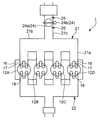
図1に示す本発明の実施形態に係る車両搭載エンジン1は、4サイクル火花点火式ガソリンエンジンであり、シリンダヘッド10及びシリンダブロック11を有する。前記エンジン1は、図2に示すように、エンジン1の一端側から順に、1番気筒12A、2番気筒12B、3番気筒12C、及び4番気筒12Dが形成されている。図1に示すように、各気筒12A〜12Dの内部に、図示しないコネクティングロッドによりクランクシャフト3に連結されたピストン13が嵌挿され、前記ピストン13の上方に燃焼室14が形成されている。各気筒12A〜12Dのピストン13は、クランクシャフト3の回転に伴い、相互にクランク角で180°(180°CA)の位相差で上下に往復運動する。
(1) Overall Configuration The vehicle-mounted
本実施形態では、1番気筒12A、3番気筒12C、4番気筒12D、2番気筒12Bの順に、吸気、圧縮、膨張、排気の各行程が行われる。
In the present embodiment, intake, compression, expansion, and exhaust strokes are performed in the order of the
シリンダヘッド10に点火プラグ15及び燃料噴射弁16が設けられている。前記点火プラグ15の電極は、燃焼室14の頂部で燃焼室14を臨んでいる。前記点火プラグ15は点火装置27で駆動される。前記燃料噴射弁16は、燃焼室14の側方から燃焼室14に燃料を直接噴射する。前記燃料噴射弁16は、図示しないニードル弁及びソレノイドを内蔵し、図4に示すエンジン制御ユニット100から入力されるパルス信号のパルス幅に対応する時間だけ開弁する。これにより、前記燃料噴射弁16の開弁時間に応じた量の燃料が前記点火プラグ15の電極付近に向けて噴射される。
A
シリンダヘッド10に、燃焼室14に開口する吸気ポート17及び排気ポート18が設けられている。前記吸気ポート17及び前記排気ポート18に吸気通路21及び排気通路22が接続され、前記吸気ポート17及び前記排気ポート18と燃焼室14との連結部分に吸気バルブ19及び排気バルブ20が配設されている。
The
図2に示すように、吸気通路21は、上流側から順に、共通吸気通路21c、サージタンク21b、及び各気筒12A〜12D毎の独立吸気通路21aを含んでいる。前記共通吸気通路21cにスロットルボディ24が設けられ、前記スロットルボディ24に、各気筒12A〜12Dに流入する空気量を調整可能なスロットル弁24a、及び前記スロットル弁24aを駆動するアクチュエータ24bが備えられている。前記スロットルボディ24の近傍に、アイドリング回転速度制御装置(ISC:Idling Speed Control device)24cが配設されている。ISC24cは、図4に示すエンジン制御ユニット100によって開弁量が変更可能な電磁駆動式のものである。スロットル弁24aの上流に、吸気流量を検出するエアフローセンサ25が配設され、スロットル弁24aの下流に、吸気圧力を検出する吸気圧センサ26が配設されている。
As shown in FIG. 2, the
図1に示すように、前記エンジン1は、タイミングベルト4によりクランクシャフト3に連結されたモータジェネレータ28を具備している。タイミングベルト4は、クランクシャフト3に組み付けられたクランクシャフト側プーリ3aと、モータジェネレータ28の駆動軸28aに組み付けられたモータジェネレータ側プーリ28bとに巻き掛けられている。前記モータジェネレータ28は、図示しないフィールドコイルの電流を制御して出力電圧を調整することにより発電量を調整するレギュレータ回路28cを有する。前記モータジェネレータ28は、図4に示すエンジン制御ユニット100から前記レギュレータ回路28cに入力される制御信号に基き、図3に示す車両電気負荷82やバッテリ6の電圧等に対応した量の電気を発電する。
As shown in FIG. 1, the
前記モータジェネレータ28は、モータジェネレータ側プーリ28bとクランクシャフト側プーリ3aとに巻き掛けられたタイミングベルト4を介してエンジン1で駆動され、減速・制動時の運動エネルギーを利用して発電を行うものであると共に、モータジェネレータ側プーリ28bとクランクシャフト側プーリ3aとに巻き掛けられたタイミングベルト4を介してクランクシャフト3を回転(クランキング)させる巻き掛け伝動式始動モータにも兼用されている。前記モータジェネレータ28は、特許請求の範囲の「高速型始動モータ」を構成する。
The
後に詳しく述べるように、減速・制動時の運動エネルギーを利用して発電を行うモータジェネレータ28を高速型始動モータに兼用するので、部品点数を削減できるという利点がある。
As will be described in detail later, since the
図1に示すように、前記エンジン1は、エンジン1の始動に用いられるスタータ36を具備している。前記スタータ36は、スタータモータ36a及びピニオンギア36dを有している。ピニオンギア36dの回転軸は、スタータモータ36aの出力軸と同軸で、前記回転軸に沿って往復移動可能である。クランクシャフト3に図示しないフライホイールが連結され、前記フライホイールにリングギア35が固定されている。前記スタータ36を用いてエンジン1を始動するときは、ピニオンギア36dが所定の噛合位置に移動し、前記リングギア35に一時的に噛合する。そして、ピニオンギヤ36dがスタータモータ36aで駆動されることにより、クランクシャフト3が回転(クランキング)される。
As shown in FIG. 1, the
前記スタータモータ36aは、ピニオンギヤ36dをリングギア35に一時的に噛合させてクランクシャフト3を回転させるギヤ式始動モータであり、特許請求の範囲の「低速型始動モータ」を構成する。
The
前記モータジェネレータ28が始動モータとして機能する場合の減速比と、前記スタータモータ36aの減速比とを比較すると、モータジェネレータ側プーリ28bとクランクシャフト側プーリ3aとの間の減速比が、ピニオンギヤ36dとリングギア35との間の減速比よりも小さい値に設定されている。そのため、クランクシャフト3の回転に対するスタータモータ36a(低速型始動モータ)の出力軸の回転が相対的に多くなり、クランクシャフト3の回転に対するモータジェネレータ28(高速型始動モータ)の駆動軸28aの回転が相対的に少なくなる。
Comparing the reduction ratio when the
前記スタータ36でエンジン1を始動させる形態は2つに大別される。1つは、運転者が図4に示すイグニションキースイッチ(IGキースイッチ)38を操作してスタータ36を駆動させ、これによりエンジン1を始動させる形態である。これは「キー始動」と称される。もう1つは、アイドルストップ機能において、エンジン1の自動停止後の再始動時に、図4に示すエンジン制御ユニット100が自動的にスタータ36を駆動させ、これによりエンジン1を始動させる形態である。これは「自動再始動」又は単に「再始動」と称される。
The form in which the
また、エンジン1の「再始動」にも、例えば運転者がアクセルペダル(図示せず)を踏み込む等、運転者の発進要求による再始動と、例えばエアコンの設定温度と車室内温度との差が大きくなったのでエアコンを稼働させる必要が生じた等、運転者の発進要求によらない再始動とがある。エンジン1の再始動時に、運転者の発進要求がある場合は、迅速なエンジン始動が求められ、運転者の発進要求がない場合は、静粛性や低振動性が求められる。
In addition, the “restart” of the
図1に示すように、前記エンジン1は、クランクシャフト3の回転角を検出する2つのクランク角度センサ30,31を具備している。一方のクランク角度センサ30から出力される検出信号(パルス信号)に基いてエンジン回転(すなわちエンジン回転数又はエンジン回転速度)が検出される。両クランク角度センサ30,31から出力される相互に位相のずれた検出信号(パルス信号)に基いてクランクシャフト3の回転角度が検出される。
As shown in FIG. 1, the
図1に示すように、前記エンジン1は、吸気側カムシャフトの回転位置を検出するカム角度センサ32、及びエンジン1の冷却水の温度を検出する水温センサ33を具備している。
As shown in FIG. 1, the
本実施形態に係る車両は、エンジン1の出力軸(クランクシャフト3)が車体幅方向に延びるように配置されたエンジン横置きのフロントエンジン・フロントドライブ(FF)車両である。また、図3に示すように、本実施形態に係る車両は、エンジン1の出力軸に自動変速機2が接続されたAT車両である。エンジン1の回転は、自動変速機2及び差動装置(図示せず)を介して左右の前輪(図示せず)に伝達される。
The vehicle according to the present embodiment is a front-engine / front-drive (FF) vehicle in which the output shaft (crankshaft 3) of the
(2)電気系統
次に、図3を参照して、本実施形態に係る車両の電気系統を説明する。
(2) Electric system Next, with reference to FIG. 3, the electric system of the vehicle which concerns on this embodiment is demonstrated.
図3に示すように、前記車両の電気系統は、各種ライトやエアコンあるいは計器類等からなる車両電気負荷82と、前記車両電気負荷82とモータジェネレータ28との間に介設されたDC/DCコンバータ5と、前記車両電気負荷82に電力を供給する鉛蓄電池からなるバッテリ6とを含んでいる。前記バッテリ6にはスタータ36も接続されている。
As shown in FIG. 3, the electric system of the vehicle includes a vehicle
前述したように、モータジェネレータ28は、モータジェネレータ側プーリ28bとクランクシャフト側プーリ3aとに巻き掛けられたタイミングベルト4を介してエンジン1の出力軸(クランクシャフト3)に連結されている。
As described above, the
車両の減速・制動時にモータジェネレータ28で発電された回生電力を蓄電するキャパシタユニット29がモータジェネレータ28と直列に接続されている。
A
前記キャパシタユニット29は、単一の電気二重層キャパシタからなるキャパシタセル(図示せず)を複数(例えば10個)直列に接続したものである。各キャパシタセルは、それぞれ内部抵抗を有している。内部抵抗の抵抗値は、一般に、新品時において1mΩ程度である。キャパシタユニット29が正常な場合のキャパシタユニット29全体の最大電圧は25.2Vである。キャパシタセルの数は状況に応じて適宜の数を選択することができる。キャパシタユニット29全体の最大電圧(25.2V)は、バッテリ6の電圧(例えば12V)より大きい。
The
車両の減速・制動時は、回生制動により、モータジェネレータ28が発電機として機能する。モータジェネレータ28の出力電圧は、インバータ28dにより交流電圧から所望の直流電圧に変換される。回生電力は、キャパシタユニット29に供給されると共に、電圧変換器としてのDC/DCコンバータ5を介してバッテリ6にも供給される。
During deceleration and braking of the vehicle, the
キャパシタユニット29に蓄積された電力は、前記DC/DCコンバータ5を介してバッテリ6に移送される。DC/DCコンバータ5は、キャパシタユニット29の側からバッテリ6の側へ降圧コンバータ機能を有する。
The electric power stored in the
キャパシタユニット29に蓄積された電力でバッテリ6を充電することにより、キャパシタユニット29に蓄積された電力の有効利用が図られる。そのうえ、バッテリ6への電力供給によりキャパシタ電圧が低下するので、キャパシタユニット29の劣化の進行が抑制される。
By charging the
図4に示すIGキースイッチ38が切られた後、再びエンジン1が「キー始動」される際には、バッテリ6からスタータ36又はモータジェネレータ28へ電力が供給される。その結果、スタータモータ36a又はモータジェネレータ28が駆動され、クランクシャフト3が回転される。
When the
エンジン1が「キー始動」された後に、キャパシタユニット29に蓄積されている電力はモータジェネレータ28の駆動に使用される。これにより、アイドルストップ機能において、自動停止しているエンジン1を「再始動」させる際に、キャパシタユニット29に残存している電力を利用することができる。これによりバッテリ6の消耗が抑制される。
After the
モータジェネレータ28での発電は、基本的に車両の減速・制動時にのみ行われ、その電力はキャパシタユニット29に集中的に充電される。これにより、減速・制動時のエネルギーが回生電力として回収される。モータジェネレータ28は、発電された交流電力を直流電力に変換するインバータ28dを内蔵している。モータジェネレータ28による発電電力は、前記インバータ28dで直流に変換された後にキャパシタユニット29に送られる。キャパシタユニット29は、最大で約25Vまで充電可能であり、これを超える分のモータジェネレータ28の発電電力については、DC/DCコンバータ5を介して(DC/DCコンバータ5で降圧されてから)バッテリ6に送られる。
Electric power generation by the
一方、減速・制動時以外の運転状態(アイドリング時、定常走行時、又は加速時)では、モータジェネレータ28での発電は基本的に行われない。すなわち、車両の減速・制動時に前記キャパシタユニット29に充電された電力は、前記DC/DCコンバータ5を介して逐次バッテリ6に送られ、そこで蓄えられる。そして、減速・制動時以外の運転状態では、前記バッテリ6に蓄えられた電力が車両電気負荷82に供給される。これにより、モータジェネレータ28を作動させることなく車両電気負荷82の電力が賄われる。もちろん、車両の走行シーンによっては、減速・制動時以外の運転状態において、モータジェネレータ28での発電が一時的に行われることがあってもよい。
On the other hand, in an operating state other than during deceleration / braking (during idling, steady running, or acceleration), the
ここで、前記のように、複数の電気二重層キャパシタを直列に接続したキャパシタユニット29と、鉛蓄電池からなるバッテリ6とを併用しているのは、キャパシタユニット29及びバッテリ6のそれぞれの特性を生かして減速・制動時のエネルギーを効率よく回収するためである。すなわち、キャパシタユニット29は、コンデンサのように電荷を物理的に蓄えるものであるため、大電流を瞬時に受け入れることが可能であり、減速・制動時にモータジェネレータ28で集中的に発電される電力を一時的に蓄電するのに適している。一方、バッテリ6は、化学反応を利用した蓄電装置であり、一時的な大電流には対応できないが、前記キャパシタユニット29に比べて充電容量が大きいという性質がある。そこで、モータジェネレータ28で発電された電力をいったんキャパシタユニット29で蓄えた後で、容量の大きいバッテリ6へと送るようにしている。なお、キャパシタユニット29に蓄えられた電力は、バッテリ6を経由することなく、車両電気負荷82に直接供給される場合もある。
Here, as described above, the
(3)制御系
(3−1)システム構成
図4は、本実施形態に係る車両のエンジン制御ユニット100を中心とする制御システム図である。
(3) Control System (3-1) System Configuration FIG. 4 is a control system diagram centering on the
エンジン制御ユニット100は、前述した、エアフローセンサ25、吸気圧センサ26、クランク角度センサ30,31、カム角度センサ32、水温センサ33、及びIGキースイッチ38等から信号を入力する。エンジン制御ユニット100は、さらに、運転者により踏み込み操作されるアクセルペダルの開度を検出するアクセル開度センサ34、ブレーキペダル(図示せず)のON/OFF(すなわちブレーキの有無)を検出するブレーキセンサ37、及び車両の車速を検出する車速センサ39等からも信号を入力する。
The
エンジン制御ユニット100は、前述した、DC/DCコンバータ5、燃料噴射弁16、スロットル弁24aのアクチュエータ24b、点火装置27、モータジェネレータ28、スタータモータ36a、及び車両電気負荷82等に制御信号を出力する。
The
エンジン制御ユニット100は、CPU、メモリ、カウンタタイマ群、インターフェース、及びこれらを接続するバスを有するマイクロプロセッサで構成されている。エンジン制御ユニット100は、運転状態判定部101、燃焼制御部102、スタータ制御部103、モータジェネレータ制御部104、電気負荷制御部106、及びアイドルストップ制御部107を論理的に構成している。
The
運転状態判定部101は、エアフローセンサ25、吸気圧センサ26、クランク角度センサ30,31、カム角度センサ32、水温センサ33、及びアクセル開度センサ34からのセンサ信号に基づき各気筒12A〜12Dのピストン13の位置や、各気筒12A〜12Dの筒内温度、又はエンジン1が正転しているか否か等、種々の運転状態を判定するものである。この運転状態判定部101は、クランク角度センサ30,31からの信号に基き、ピストン13の位置を演算し、エンジン1が自動停止しているときの各ピストン13の停止位置を判定するものでもある。
The operating
燃焼制御部102は、エアフローセンサ25、吸気圧センサ26、クランク角度センサ30,31、カム角度センサ32、水温センサ33、及びアクセル開度センサ34からの信号に基き、エンジン1の適正なスロットル開度(吸気量)、燃料噴射量、燃料噴射タイミング、及び点火時期を設定し、その制御信号を燃料噴射弁16、スロットル弁24aのアクチュエータ24b、点火装置27に出力する。
スタータ制御部103は、エンジン1の「キー始動」及び「再始動」において、スタータ36に制御信号を出力し、スタータモータ36aを駆動させる。
The
モータジェネレータ制御部104は、モータジェネレータ28の適切な発電量を設定し、その駆動信号を前記レギュレータ回路28cに出力する。通常は、出力電圧(レギュレート電圧)の目標値(例えば13V)が設定され、エンジン回転等が変動してもその目標値を維持するように発電量をフィードバック制御する。
The motor
電気負荷制御部106は、運転者や搭乗者のスイッチ操作に基いて、又は自動的に、車両電気負荷82を作動させ、又は車両電気負荷82の作動状態を変化させる。車両電気負荷82は、すでに述べたものの他、例えば、エアバッグコントロールユニット、電子油圧式パワーステアリングコントロールユニット、ナビゲーションシステム、オーディオ、各種メータ類、各種ライト、デフォッガ等が挙げられる。電気負荷制御部105は、スタータ36の駆動時に、スタータ36への電力供給をより多く確保するために、必要に応じて車両電気負荷82への電力供給を制限する。
The electric
アイドルストップ制御部107は、所定の自動停止条件が成立したときにエンジン1を自動停止させ、その後、所定の再始動条件が成立したときにエンジン1を再始動させるアイドルストップ機能を実現する。
The idle
前記エンジン制御ユニット100は、特許請求の範囲の「再始動制御手段」を構成する。
The
(3−2)特徴的動作と作用
前記エンジン制御ユニット100が行う特徴的動作を説明する。図5〜図7は、本実施形態に係るエンジン1の再始動時の回転変化を示すタイムチャートである。
(3-2) Characteristic Operation and Action Characteristic operation performed by the
運転者がブレーキペダルを踏み込んだ状態で車速が略ゼロになる等、所定の自動停止条件が成立すると、アイドルストップ機能が作動して、エンジン1が自動停止する。このエンジン1の自動停止中に、所定の再始動条件が成立すると、アイドルストップ機能が解除されて、エンジン1が再始動する。
When a predetermined automatic stop condition is satisfied, such as when the vehicle speed is substantially zero while the driver depresses the brake pedal, the idle stop function is activated and the
前述したように、アイドルストップ中のエンジン1の再始動条件として、例えば運転者がアクセルペダルを踏み込む等、運転者の発進要求を含むものと、例えばエアコンの設定温度と車室内温度との差が大きくなったのでエアコンを稼働させる必要が生じた等、運転者の発進要求を含まないものとがある。エンジン1の再始動時に、運転者の発進要求がある場合は、迅速なエンジン始動が求められ、運転者の発進要求がない場合は、静粛性や低振動性が求められる。
As described above, as a restart condition of the
そこで、本実施形態では、アイドルストップ中のエンジン1を再始動させる際に、運転者の発進要求がある場合とない場合とで、モータジェネレータ28とスタータモータ36aとの2つの始動モータを使い分けるようにした。さらに、本実施形態では、運転者の発進要求があり、且つ、その度合いが相対的に大きい場合と、運転者の発進要求があり、且つ、その度合いが相対的に小さい場合とでも、モータジェネレータ28とスタータモータ36aとの2つの始動モータを使い分けるようにした。なお、運転者の発進要求の度合いは、例えば、アクセルペダルを踏み込んでいるか否かや、アクセルペダルを踏み込んでいる場合の踏込量等で判断できる。
Therefore, in the present embodiment, when restarting the
[運転者の発進要求があり且つその度合いが相対的に大きい場合]
例えば、運転者がブレーキペダルの踏み込みを解除し且つアクセルペダルの踏込量が相対的に大きい等、運転者の発進要求の度合いが相対的に大きい場合は、図5に示すように、前記スタータモータ36aと前記モータジェネレータ28との両モータを駆動してエンジン1を再始動させる。これにより、エンジン1を迅速に始動することができる。
[When there is a driver's start request and the degree is relatively large]
For example, as shown in FIG. 5, when the driver releases the brake pedal and the degree of the driver's start request is relatively large, such as when the amount of depression of the accelerator pedal is relatively large, the starter motor Both the
また、始動モータ36a,28の駆動開始と共に燃料供給を開始して燃焼を行う(図中、△印は燃料噴射を表す。図6及び図7において同様。)。これにより、エンジン1をさらに迅速に始動することができる。なお、スタータモータ36aは低速型始動モータであり、モータジェネレータ28は高速型始動モータであるから、スタータモータ36aは相対的に早い時点t1で駆動が停止され、モータジェネレータ28は相対的に遅い時点t2で駆動が停止される。
In addition, fuel supply is started and combustion is started at the start of driving of the
なお、スタータモータ36aとモータジェネレータ28とを同時に駆動開始してもよいが、先にスタータモータ36aの駆動を開始した後、遅れてモータジェネレータ28の駆動を開始することが好ましい。先にスタータモータ36aの駆動を開始するので、ピニオンギヤ36dとリングギア35とを停止状態で噛合させることができ、ギヤ式始動モータであるスタータモータ36aの駆動を円滑に開始することができる。また、クランクシャフト3が回転している状態で巻き掛け伝動式始動モータであるモータジェネレータ28の駆動を開始するので、タイミングベルト4の滑りを抑制できる。さらに、モータジェネレータ28の駆動を遅らせずに開始する場合に比べて、モータジェネレータ28の駆動時間が短くなるので、消費電力が少なくて済む。一方、スタータモータ36aとモータジェネレータ28とを併せて駆動するので、始動時間が短くなり、迅速始動性が保たれる。
Although
また、スタータモータ36aの駆動を開始した後、遅れてモータジェネレータ28の駆動を開始する場合に、運転者の発進要求の度合いが大きいほど、モータジェネレータ28の駆動の開始を遅らせる時間を短くすることが好ましい。運転者の発進要求の度合いが大きいほど、エンジン1をより迅速に始動できるという利点がある。
In addition, when starting the
[運転者の発進要求があり且つその度合いが相対的に小さい場合]
例えば、運転者がブレーキペダルの踏み込みを解除しただけでアクセルペダルを踏み込まない、あるいはアクセルペダルの踏込量が相対的に小さい等、運転者の発進要求の度合いが相対的に小さい場合は、図6に示すように、前記モータジェネレータ28のみを駆動してエンジン1を再始動させる。これにより、エンジン1の迅速始動性よりも、始動時の静粛性を確保することが優先される。
[When there is a driver's start request and the degree is relatively small]
For example, in the case where the degree of the driver's start request is relatively small, such as when the driver only depresses the brake pedal and does not depress the accelerator pedal, or the amount of depression of the accelerator pedal is relatively small, FIG. As shown, the
モータジェネレータ28が静粛性に優れる理由は、前述したように、クランクシャフト3の回転に対するモータジェネレータ28の駆動軸28aの回転が相対的に少ないこと、駆動形式がベルト4及びプーリ3a,28bによる巻き掛け伝動式であること等による。エンジン回転の上昇が図5の場合に比べて遅いため、モータジェネレータ28は、図5の時点t2よりも遅い時点t3で駆動が停止される。
The reason why the
[運転者の発進要求がない場合]
例えば、エアコンを稼働させる必要が生じた、アイドルストップ時間が長時間に及んだ等、システム上の理由でエンジン1を再始動させる場合は、運転者の発進要求がない。この場合は、図7に示すように、前記モータジェネレータ28のみを駆動してエンジン1を再始動させる。これにより、エンジン1の迅速始動性よりも、始動時の静粛性を確保することが優先される。運転者は、エンジン1が再始動することを知らないから、始動時の静粛性を確保することの利点は大きい。
[When there is no driver's start request]
For example, when the
また、燃料供給は、モータジェネレータ28の駆動開始と共に開始するのではなく、所定時間遅らせて開始する。あるいは、エンジン回転が所定回転(例えば400〜500rpm)以上となったときに開始する。これにより、エンジン1の共振周波数(例えば200〜300Hz)を超えてから燃焼が開始するので、始動時の低振動性ひいては低騒音性が確保される。これも、運転者は、エンジン1が再始動することを知らないから、始動時の低振動性ひいては低騒音性が確保されることの利点は大きい。また、エンジン回転が上昇し、所定回転以上となってから燃焼が開始するので、燃焼が安定し、エミッション性能が向上するという利点もある。エンジン回転の上昇が図6の場合に比べてさらに遅いため、モータジェネレータ28は、図6の時点t3よりもさらに遅い時点t4で駆動が停止される。
Further, the fuel supply is not started when the
(3−3)制御動作
次に、フローチャートを参照して、エンジン制御ユニット100が行うアイドルストップ制御の具体的動作を説明する。
(3-3) Control Operation Next, a specific operation of the idle stop control performed by the
[自動停止制御]
エンジン1の自動停止制御は、図8に示すフローチャートに従って実行される。この制御が開始すると、エンジン制御ユニット100は、ステップS1で、各種センサ値を読み込んだ後、ステップS2で、エンジン1の自動停止条件が成立したか否かを判定する。
[Automatic stop control]
The automatic stop control of the
本実施形態では、エンジン制御ユニット100は、IGキースイッチ38がオンであること、Dレンジ等の走行レンジが選択されていること、車速が所定車速以下(車速がゼロの状態や車両がクリープ力で動いている状態を含む)であること、及びブレーキ踏込量が所定の踏込量以上(ブレーキ油圧が所定の油圧以上)であることの全てが満足されたときに、前記自動停止条件が成立したと判定する。
In the present embodiment, the
その結果、前記自動停止条件が成立したと判定したときは、エンジン制御ユニット100は、ステップS3で、燃料噴射弁16からの燃料噴射を停止する燃料カットを開始すると共に、主として掃気のためにスロットル弁24aを開弁する(スロットル弁24aの開度をそれまでの開度よりも大きくする)。
As a result, when it is determined that the automatic stop condition is satisfied, the
次いで、エンジン制御ユニット100は、ステップS4で、エンジン回転が第1所定回転N1以下か否かを判定する。その結果、エンジン回転が第1所定回転N1以下と判定したときは、エンジン制御ユニット100は、ステップS5で、スロットル弁24aを閉弁する(スロットル弁24aの開度をそれまでの開度よりも小さくする)。
Next, the
次いで、エンジン制御ユニット100は、ステップS6で、エンジン1が完全に停止したか否かを判定する。その結果、エンジン1が完全に停止したと判定したときは、エンジン制御ユニット100は、ステップS7で、クランク角度センサ30,31からの信号に基き、各ピストン13の停止位置を記憶する。そして、この制御が終了する。
Next, the
[再始動制御]
エンジン1の再始動制御は、図9及び図10に示すフローチャートに従って実行される。この制御が開始すると、エンジン制御ユニット100は、ステップS11で、各種センサ値を読み込んだ後、ステップS12で、エンジン1の再始動条件が成立したか否かを判定する。
[Restart control]
The restart control of the
本実施形態では、エンジン制御ユニット100は、IGキースイッチ38がオンであること、Dレンジ等の走行レンジが選択されていること、車速が所定車速以下であること、及びブレーキセンサ37からの信号がOFF(ブレーキペダル未踏込)であることの全てが満足されたときに、前記再始動条件が成立したと判定する。つまり、運転者の発進要求がある場合に、前記再始動条件は成立したと判定される。
In the present embodiment, the
本実施形態では、エンジン制御ユニット100は、前記要件以外に、例えば、エアコンの設定温度と車室内温度との差が大きくなったこと、アイドルストップ時間が長時間に及んだこと等、システム上の理由からエンジン1を再始動させる必要が生じたときにも、前記再始動条件が成立したと判定する。つまり、運転者の発進要求がない場合にも、前記再始動条件は成立したと判定される。
In the present embodiment, in addition to the above requirements, for example, the
その結果、前記再始動条件が成立したと判定したときは、エンジン制御ユニット100は、ステップS13で、ブレーキセンサ37からの信号がOFF(ブレーキペダル未踏込)であるか否かを判定する。その結果、ブレーキセンサ37からの信号がOFFであると判定したときは、エンジン制御ユニット100は、ステップS14で、アクセル開度センサ34からの信号がON(アクセルペダル踏込)であるか否かを判定する。その結果、アクセル開度センサ34からの信号がONであると判定したときは、エンジン制御ユニット100は、ステップS15に進む。これは、運転者の発進要求があり且つその度合いが相対的に大きい場合であって、前述の図5に示すような制御動作が行われる。
As a result, when it is determined that the restart condition is satisfied, the
一方、前記ステップS14の判定の結果、アクセル開度センサ34からの信号がOFF(アクセルペダル未踏込)であると判定したときは、エンジン制御ユニット100は、ステップS22に進む。これは、運転者の発進要求があり且つその度合いが相対的に小さい場合であって、前述の図6に示すような制御動作が行われる。
On the other hand, as a result of the determination in step S14, when it is determined that the signal from the
また、一方、前記ステップS13の判定の結果、ブレーキセンサ37からの信号がON(ブレーキペダル踏込)であると判定したときは、エンジン制御ユニット100は、ステップS25に進む。これは、運転者の発進要求がない場合であって、前述の図7に示すような制御動作が行われる。
On the other hand, as a result of the determination in step S13, when it is determined that the signal from the
運転者の発進要求があり且つその度合いが相対的に大きい場合、エンジン制御ユニット100は、ステップS15で、停止時膨張行程気筒(エンジン1の自動停止中に膨張行程にある気筒のこと)にピストン13の停止位置を考量して設定した量の燃料を噴射し、且つ、スタータモータ36aとモータジェネレータ28とを同時に駆動開始する。
When there is a driver's start request and the degree thereof is relatively large, the
次いで、エンジン制御ユニット100は、ステップS16で、噴射した燃料の気化時間を考慮して設定したタイミングで前記停止時膨張行程気筒に対して点火を行う。
Next, in step S16, the
次いで、エンジン制御ユニット100は、ステップS17で、順次他の気筒に対して圧縮行程で継続して燃焼を行い、ステップS18で、エンジン回転が第3所定回転N3(例えば300rpm)以上か否かを判定する。その結果、エンジン回転が第3所定回転N3以上と判定したときは、エンジン制御ユニット100は、ステップS19で、スタータモータ36aの駆動を停止させる(時点t1)。
Next, in step S17, the
次いで、エンジン制御ユニット100は、ステップS20で、エンジン回転がアイドル回転(例えば700rpm)以上か否かを判定する。その結果、エンジン回転がアイドル回転以上と判定したときは、エンジン制御ユニット100は、ステップS21で、モータジェネレータ28の駆動を停止させる(時点t2)。そして、この制御が終了する。この制御動作の特徴及び作用は図5を参照してすでに述べたのでここでは繰り返さない。
Next, in step S20, the
一方、運転者の発進要求があり且つその度合いが相対的に小さい場合、エンジン制御ユニット100は、ステップS22で、停止時膨張行程気筒にピストン13の停止位置を考量して設定した量の燃料を噴射し、且つ、モータジェネレータ28のみを駆動開始する。
On the other hand, when there is a driver's start request and the degree thereof is relatively small, the
次いで、エンジン制御ユニット100は、ステップS23で、噴射した燃料の気化時間を考慮して設定したタイミングで前記停止時膨張行程気筒に対して点火を行う。
Next, in step S23, the
次いで、エンジン制御ユニット100は、ステップS24で、順次他の気筒に対して圧縮行程で継続して燃焼を行う。
Next, in step S24, the
次いで、エンジン制御ユニット100は、ステップS20で、エンジン回転がアイドル回転以上か否かを判定する。その結果、エンジン回転がアイドル回転以上と判定したときは、エンジン制御ユニット100は、ステップS21で、モータジェネレータ28の駆動を停止させる(時点t3)。そして、この制御が終了する。この制御動作の特徴及び作用は図6を参照してすでに述べたのでここでは繰り返さない。
Next, the
また、一方、運転者の発進要求がない場合、エンジン制御ユニット100は、ステップS25で、モータジェネレータ28のみを駆動開始する。
On the other hand, when there is no driver start request, the
次いで、エンジン制御ユニット100は、ステップS26で、エンジン回転が第2所定回転N2(例えば400〜500rpm)以上か否かを判定する。その結果、エンジン回転が第2所定回転N2以上と判定したときは、エンジン制御ユニット100は、ステップS27で、次の圧縮行程気筒にエンジントルクを考量して設定した量の燃料を噴射する。
Next, in step S26, the
次いで、エンジン制御ユニット100は、ステップS28で、噴射した燃料の気化時間を考慮して設定したタイミングで前記圧縮行程気筒に対して点火を行う。
Next, in step S28, the
次いで、エンジン制御ユニット100は、ステップS29で、順次他の気筒に対して圧縮行程で継続して燃焼を行う。
Next, in step S29, the
次いで、エンジン制御ユニット100は、ステップS20で、エンジン回転がアイドル回転以上か否かを判定する。その結果、エンジン回転がアイドル回転以上と判定したときは、エンジン制御ユニット100は、ステップS21で、モータジェネレータ28の駆動を停止させる(時点t4)。そして、この制御が終了する。この制御動作の特徴及び作用は図7を参照してすでに述べたのでここでは繰り返さない。
Next, the
(4)他の変形例
運転者の発進要求の度合いが相対的に小さい場合(図6参照)に、燃料供給を、モータジェネレータ28の駆動開始と共に開始するのではなく、所定時間遅らせて開始、あるいは、エンジン回転が所定回転(例えば400〜500rpm)以上となったときに開始してもよい。これにより、エンジン1の共振周波数(例えば200〜300Hz)を超えてから燃焼が開始するので、始動時の低振動性ひいては低騒音性が確保される。また、エンジン回転が上昇し、所定回転以上となってから燃焼が開始するので、燃焼が安定し、エミッション性能が向上するという利点もある。
(4) Other Modifications When the degree of the driver's start request is relatively small (see FIG. 6), the fuel supply is not started with the start of driving of the
電気系統(図3参照)は、状況に応じて、キャパシタユニット29のない1電源系でも構わない。あるいは、キャパシタユニット29に代えて、第2のバッテリを備えて、2つのバッテリを有する2電源系とすることもできる。
The electric system (see FIG. 3) may be a single power supply system without the
エンジンは、ガソリンエンジンに限らず、圧縮自己着火式エンジンでも構わない。圧縮自己着火式エンジンの例として、軽油を自己着火により燃焼させるディーゼルエンジンや、ガソリンを含む燃料を高圧縮比で圧縮して自己着火させる予混合圧縮着火(HCCI:Homogeneous-Charge Compression Ignition)型エンジン等が挙げられる。 The engine is not limited to a gasoline engine, and may be a compression self-ignition engine. Examples of compression self-ignition engines include diesel engines that burn light oil by self-ignition, and premixed compression ignition (HCCI) engines that self-ignite by compressing fuel containing gasoline at a high compression ratio. Etc.
1 エンジン
3 クランクシャフト
3a クランクシャフト側プーリ(クランクシャフト側回転体)
4 タイミングベルト(巻き掛け部材)
28 モータジェネレータ(高速型始動モータ)
28a モータジェネレータ駆動軸(モータ出力軸)
28b モータジェネレータ側プーリ(モータ側回転体)
35 リングギヤ(クランクシャフト側ギヤ)
36a スタータモータ(低速型始動モータ)
36d ピニオンギヤ(モータ側ギヤ)
100 エンジン制御ユニット(再始動制御手段)
1
4 Timing belt (winding member)
28 Motor generator (high speed starter motor)
28a Motor generator drive shaft (motor output shaft)
28b Motor generator side pulley (motor side rotating body)
35 Ring gear (crankshaft side gear)
36a Starter motor (low speed starter motor)
36d Pinion gear (motor side gear)
100 engine control unit (restart control means)
Claims (7)
クランクシャフトの回転に対するモータ出力軸の回転が相対的に多い低速型始動モータと、
クランクシャフトの回転に対するモータ出力軸の回転が相対的に少ない高速型始動モータと、
エンジンの再始動時に、運転者の発進要求がある場合は、前記低速型始動モータと前記高速型始動モータとを駆動してエンジンを再始動させ、運転者の発進要求がない場合は、前記高速型始動モータのみを駆動してエンジンを再始動させる再始動制御手段とが備えられていることを特徴とする車両搭載エンジンの始動装置。 A starter for a vehicle-mounted engine that restarts an engine that is automatically stopped when a predetermined restart condition is satisfied,
A low speed starter motor in which the rotation of the motor output shaft relative to the rotation of the crankshaft is relatively large;
A high-speed starter motor in which the rotation of the motor output shaft relative to the rotation of the crankshaft is relatively small;
When there is a driver's start request when the engine is restarted, the engine is restarted by driving the low speed start motor and the high speed start motor, and when there is no driver start request, the high speed A vehicle-mounted engine starter characterized by comprising restart control means for driving only the mold starter motor to restart the engine.
前記再始動制御手段は、運転者の発進要求があり、且つ、その度合いが相対的に大きい場合は、前記低速型始動モータと前記高速型始動モータとを駆動してエンジンを再始動させ、運転者の発進要求があり、且つ、その度合いが相対的に小さい場合は、前記高速型始動モータのみを駆動してエンジンを再始動させることを特徴とする車両搭載エンジンの始動装置。 The starter for a vehicle-mounted engine according to claim 1,
The restart control means restarts the engine by driving the low-speed start motor and the high-speed start motor when there is a driver's start request and the degree is relatively large. A vehicle-mounted engine starter that drives only the high-speed start motor and restarts the engine when there is a start request from a person and the degree is relatively small.
前記再始動制御手段は、運転者の発進要求がない場合又は運転者の発進要求の度合いが相対的に小さい場合は、運転者の発進要求の度合いが相対的に大きい場合に比べて、燃料供給の開始を遅らせることを特徴とする車両搭載エンジンの始動装置。 The starter for a vehicle-mounted engine according to claim 2,
The restart control means supplies fuel when there is no driver's start request or when the driver's start request is relatively small compared to when the driver's start request is relatively high. A starter for a vehicle-mounted engine characterized by delaying the start of the vehicle.
前記再始動制御手段は、運転者の発進要求の度合いが相対的に大きい場合は、前記始動モータの駆動開始と共に燃料供給を開始し、運転者の発進要求がない場合又は運転者の発進要求の度合いが相対的に小さい場合は、エンジン回転が所定回転以上となったときに燃料供給を開始することを特徴とする車両搭載エンジンの始動装置。 The starter for a vehicle-mounted engine according to claim 3,
When the driver's start request is relatively large, the restart control means starts the fuel supply at the same time as the start of the driving of the starter motor, and when there is no driver start request or the driver's start request A starter for a vehicle-mounted engine, characterized in that, when the degree is relatively small, fuel supply is started when the engine rotation becomes equal to or higher than a predetermined rotation.
前記低速型始動モータは、モータ側ギヤをクランクシャフト側ギヤに一時的に噛合させてクランクシャフトを回転させるギヤ式始動モータであり、
前記高速型始動モータは、モータ側回転体とクランクシャフト側回転体とに巻き掛けられた巻き掛け部材を介してクランクシャフトを回転させる巻き掛け伝動式始動モータであり、
前記再始動制御手段は、運転者の発進要求がある場合は、先に前記低速型始動モータの駆動を開始した後、遅れて前記高速型始動モータの駆動を開始することを特徴とする車両搭載エンジンの始動装置。 The starter for a vehicle-mounted engine according to any one of claims 1 to 4,
The low-speed starter motor is a gear-type starter motor that rotates the crankshaft by temporarily engaging the motor-side gear with the crankshaft-side gear,
The high-speed type starter motor is a winding transmission type starter motor that rotates a crankshaft via a winding member wound around a motor side rotating body and a crankshaft side rotating body,
The restart control means, when there is a driver's start request, starts driving the low speed starter motor first and then starts driving the high speed starter motor with a delay. Engine starter.
前記高速型始動モータは、巻き掛け部材を介してエンジンで駆動されるモータジェネレータであることを特徴とする車両搭載エンジンの始動装置。 The starter for a vehicle-mounted engine according to any one of claims 1 to 5,
The high-speed starter motor is a motor generator driven by the engine via a winding member, and is a starter for a vehicle-mounted engine.
前記再始動制御手段は、運転者の発進要求がある場合は、前記低速型始動モータと前記高速型始動モータとのうち一方の始動モータの駆動を先に開始した後、遅れて他方の始動モータの駆動を開始し、且つ、運転者の発進要求の度合いが大きいほど、他方の始動モータの駆動の開始を遅らせる時間を短くすることを特徴とする車両搭載エンジンの始動装置。 The starter for a vehicle-mounted engine according to any one of claims 1 to 6,
When there is a driver's start request, the restart control means starts driving one of the low-speed start motor and the high-speed start motor first, and then delays the other start motor. The starter for a vehicle-mounted engine is characterized in that the time for delaying the start of driving of the other starter motor is shortened as the degree of the driver's start request increases.
Priority Applications (1)
| Application Number | Priority Date | Filing Date | Title |
|---|---|---|---|
| JP2012061710A JP5910211B2 (en) | 2012-03-19 | 2012-03-19 | Starter for vehicle-mounted engine |
Applications Claiming Priority (1)
| Application Number | Priority Date | Filing Date | Title |
|---|---|---|---|
| JP2012061710A JP5910211B2 (en) | 2012-03-19 | 2012-03-19 | Starter for vehicle-mounted engine |
Publications (2)
| Publication Number | Publication Date |
|---|---|
| JP2013194584A true JP2013194584A (en) | 2013-09-30 |
| JP5910211B2 JP5910211B2 (en) | 2016-04-27 |
Family
ID=49393868
Family Applications (1)
| Application Number | Title | Priority Date | Filing Date |
|---|---|---|---|
| JP2012061710A Expired - Fee Related JP5910211B2 (en) | 2012-03-19 | 2012-03-19 | Starter for vehicle-mounted engine |
Country Status (1)
| Country | Link |
|---|---|
| JP (1) | JP5910211B2 (en) |
Cited By (12)
| Publication number | Priority date | Publication date | Assignee | Title |
|---|---|---|---|---|
| JP2016094918A (en) * | 2014-11-17 | 2016-05-26 | いすゞ自動車株式会社 | Starting device of diesel engine |
| JP2016118126A (en) * | 2014-12-19 | 2016-06-30 | マツダ株式会社 | Stop control device for engine |
| JP2016118127A (en) * | 2014-12-19 | 2016-06-30 | マツダ株式会社 | Automatic stop control device for engine |
| JP2016125344A (en) * | 2014-12-26 | 2016-07-11 | 日立オートモティブシステムズ株式会社 | Engine control device |
| DE102016214984A1 (en) | 2016-02-09 | 2017-08-10 | Mitsubishi Electric Corporation | Engine start control device and engine start control method |
| JP2018035739A (en) * | 2016-08-31 | 2018-03-08 | トヨタ自動車株式会社 | Control device of internal combustion engine |
| JP6333442B1 (en) * | 2017-05-18 | 2018-05-30 | 三菱電機株式会社 | Engine starter |
| JP6333443B1 (en) * | 2017-05-18 | 2018-05-30 | 三菱電機株式会社 | Engine starter |
| WO2018100698A1 (en) * | 2016-11-30 | 2018-06-07 | マツダ株式会社 | Method and device for controlling starting of engine |
| JP2019137270A (en) * | 2018-02-13 | 2019-08-22 | トヨタ自動車株式会社 | Engine start control device for vehicle |
| US10883464B2 (en) | 2016-11-30 | 2021-01-05 | Mazda Motor Corporation | Method and device for controlling compression ignition engine |
| WO2022059082A1 (en) * | 2020-09-16 | 2022-03-24 | 日産自動車株式会社 | Method for controlling internal combustion engine and device for controlling internal combustion engine |
Families Citing this family (1)
| Publication number | Priority date | Publication date | Assignee | Title |
|---|---|---|---|---|
| US11598305B2 (en) | 2019-11-27 | 2023-03-07 | Caterpillar Inc. | Engine idling reduction system |
Citations (7)
| Publication number | Priority date | Publication date | Assignee | Title |
|---|---|---|---|---|
| JP2000145496A (en) * | 1998-11-11 | 2000-05-26 | Toyota Motor Corp | Start controller of internal combustion engine |
| JP2000161102A (en) * | 1998-09-25 | 2000-06-13 | Toyota Motor Corp | Starting control device for engine |
| JP2000204997A (en) * | 1999-01-19 | 2000-07-25 | Mitsubishi Motors Corp | Engine starting device for vehicle |
| JP2006132466A (en) * | 2004-11-08 | 2006-05-25 | Toyota Motor Corp | Movable body and method of controlling the same |
| JP2006183467A (en) * | 2004-12-24 | 2006-07-13 | Mazda Motor Corp | Control device of vehicle |
| JP2006348868A (en) * | 2005-06-17 | 2006-12-28 | Denso Corp | Engine starting system |
| JP2010188948A (en) * | 2009-02-20 | 2010-09-02 | Nissan Motor Co Ltd | Engine start control device for hybrid car |
-
2012
- 2012-03-19 JP JP2012061710A patent/JP5910211B2/en not_active Expired - Fee Related
Patent Citations (7)
| Publication number | Priority date | Publication date | Assignee | Title |
|---|---|---|---|---|
| JP2000161102A (en) * | 1998-09-25 | 2000-06-13 | Toyota Motor Corp | Starting control device for engine |
| JP2000145496A (en) * | 1998-11-11 | 2000-05-26 | Toyota Motor Corp | Start controller of internal combustion engine |
| JP2000204997A (en) * | 1999-01-19 | 2000-07-25 | Mitsubishi Motors Corp | Engine starting device for vehicle |
| JP2006132466A (en) * | 2004-11-08 | 2006-05-25 | Toyota Motor Corp | Movable body and method of controlling the same |
| JP2006183467A (en) * | 2004-12-24 | 2006-07-13 | Mazda Motor Corp | Control device of vehicle |
| JP2006348868A (en) * | 2005-06-17 | 2006-12-28 | Denso Corp | Engine starting system |
| JP2010188948A (en) * | 2009-02-20 | 2010-09-02 | Nissan Motor Co Ltd | Engine start control device for hybrid car |
Cited By (21)
| Publication number | Priority date | Publication date | Assignee | Title |
|---|---|---|---|---|
| JP2016094918A (en) * | 2014-11-17 | 2016-05-26 | いすゞ自動車株式会社 | Starting device of diesel engine |
| JP2016118126A (en) * | 2014-12-19 | 2016-06-30 | マツダ株式会社 | Stop control device for engine |
| JP2016118127A (en) * | 2014-12-19 | 2016-06-30 | マツダ株式会社 | Automatic stop control device for engine |
| JP2016125344A (en) * | 2014-12-26 | 2016-07-11 | 日立オートモティブシステムズ株式会社 | Engine control device |
| DE102016214984A1 (en) | 2016-02-09 | 2017-08-10 | Mitsubishi Electric Corporation | Engine start control device and engine start control method |
| JP2018035739A (en) * | 2016-08-31 | 2018-03-08 | トヨタ自動車株式会社 | Control device of internal combustion engine |
| US10890122B2 (en) | 2016-11-30 | 2021-01-12 | Mazda Motor Corporation | Method and device for controlling starting of engine |
| JPWO2018100698A1 (en) * | 2016-11-30 | 2019-08-08 | マツダ株式会社 | Engine start control method and start control device |
| WO2018100698A1 (en) * | 2016-11-30 | 2018-06-07 | マツダ株式会社 | Method and device for controlling starting of engine |
| US10883464B2 (en) | 2016-11-30 | 2021-01-05 | Mazda Motor Corporation | Method and device for controlling compression ignition engine |
| US11098687B2 (en) | 2017-05-18 | 2021-08-24 | Mitsubishi Electric Corporation | Engine starting device |
| JP2018193937A (en) * | 2017-05-18 | 2018-12-06 | 三菱電機株式会社 | Engine starting device |
| JP2018193936A (en) * | 2017-05-18 | 2018-12-06 | 三菱電機株式会社 | Engine starting device |
| WO2018212020A1 (en) | 2017-05-18 | 2018-11-22 | 三菱電機株式会社 | Engine-starting apparatus |
| JP6333442B1 (en) * | 2017-05-18 | 2018-05-30 | 三菱電機株式会社 | Engine starter |
| JP6333443B1 (en) * | 2017-05-18 | 2018-05-30 | 三菱電機株式会社 | Engine starter |
| JP2019137270A (en) * | 2018-02-13 | 2019-08-22 | トヨタ自動車株式会社 | Engine start control device for vehicle |
| JP7010044B2 (en) | 2018-02-13 | 2022-01-26 | トヨタ自動車株式会社 | Vehicle engine start control device |
| WO2022059082A1 (en) * | 2020-09-16 | 2022-03-24 | 日産自動車株式会社 | Method for controlling internal combustion engine and device for controlling internal combustion engine |
| JP7302751B2 (en) | 2020-09-16 | 2023-07-04 | 日産自動車株式会社 | Internal combustion engine control method and internal combustion engine control device |
| US11788482B1 (en) | 2020-09-16 | 2023-10-17 | Nissan Motor Co., Ltd. | Method for controlling internal combustion engine and device for controlling internal combustion engine |
Also Published As
| Publication number | Publication date |
|---|---|
| JP5910211B2 (en) | 2016-04-27 |
Similar Documents
| Publication | Publication Date | Title |
|---|---|---|
| JP5910211B2 (en) | Starter for vehicle-mounted engine | |
| JP3941705B2 (en) | Internal combustion engine stop / start control device | |
| RU152687U1 (en) | HYBRID DRIVE VEHICLE SYSTEM | |
| JP4293138B2 (en) | Control device for internal combustion engine and automobile equipped with the control device | |
| CN107345500B (en) | Method and system for engine control | |
| JP3794389B2 (en) | Stop control device for internal combustion engine | |
| US8718857B2 (en) | Method and system for valve operation control | |
| JP5632882B2 (en) | Catalyst warm-up control device for hybrid vehicle | |
| US20160288784A1 (en) | Hybrid vehicle, control device for hybrid vehicle, and control method for hybrid vehicle with controller for managing the output of a battery in case of engine decompression situation | |
| US20160244064A1 (en) | Hybrid vehicle, controller for hybrid vehicle, and control method for hybrid vehicle for reducing the compression ratio at start-up of the engine according a battery level | |
| US9815452B2 (en) | Hybrid vehicle, controller for hybrid vehicle, and control method for hybrid vehicle with two stages catalyst warm-up in relationship with variable intake valve timing | |
| JP2007224848A (en) | Internal combustion engine controller | |
| US20150175157A1 (en) | Hybrid vehicle | |
| JP2014092066A (en) | EGR valve fault detection device | |
| JP3951924B2 (en) | Internal combustion engine stop / start control device | |
| JP2004232489A (en) | Starting control device of internal combustion engine | |
| JP2008296630A (en) | Control device for vehicle | |
| JP5899611B2 (en) | Control device for hybrid vehicle | |
| RU2742307C1 (en) | Power transmission system | |
| JP5949369B2 (en) | Stop control device for internal combustion engine | |
| CN108930599B (en) | Vehicle and control method of vehicle | |
| JP2001280185A (en) | Start control device for internal combustion engine and vehicle having it | |
| JP6891486B2 (en) | Hybrid vehicle drive controller | |
| JP2001304005A (en) | Automatic operation stop control for internal compustion engine | |
| JP4066832B2 (en) | Control device for internal combustion engine |
Legal Events
| Date | Code | Title | Description |
|---|---|---|---|
| A621 | Written request for application examination |
Free format text: JAPANESE INTERMEDIATE CODE: A621 Effective date: 20150119 |
|
| A977 | Report on retrieval |
Free format text: JAPANESE INTERMEDIATE CODE: A971007 Effective date: 20151112 |
|
| A131 | Notification of reasons for refusal |
Free format text: JAPANESE INTERMEDIATE CODE: A131 Effective date: 20151117 |
|
| A521 | Request for written amendment filed |
Free format text: JAPANESE INTERMEDIATE CODE: A523 Effective date: 20160118 |
|
| TRDD | Decision of grant or rejection written | ||
| A01 | Written decision to grant a patent or to grant a registration (utility model) |
Free format text: JAPANESE INTERMEDIATE CODE: A01 Effective date: 20160301 |
|
| A61 | First payment of annual fees (during grant procedure) |
Free format text: JAPANESE INTERMEDIATE CODE: A61 Effective date: 20160314 |
|
| R150 | Certificate of patent or registration of utility model |
Ref document number: 5910211 Country of ref document: JP Free format text: JAPANESE INTERMEDIATE CODE: R150 |
|
| LAPS | Cancellation because of no payment of annual fees |