WO2017195595A1 - Pièce métallique pour borne - Google Patents
Pièce métallique pour borne Download PDFInfo
- Publication number
- WO2017195595A1 WO2017195595A1 PCT/JP2017/016478 JP2017016478W WO2017195595A1 WO 2017195595 A1 WO2017195595 A1 WO 2017195595A1 JP 2017016478 W JP2017016478 W JP 2017016478W WO 2017195595 A1 WO2017195595 A1 WO 2017195595A1
- Authority
- WO
- WIPO (PCT)
- Prior art keywords
- plating
- main body
- region
- terminal fitting
- piece
- Prior art date
Links
Images


Classifications
-
- H—ELECTRICITY
- H01—ELECTRIC ELEMENTS
- H01R—ELECTRICALLY-CONDUCTIVE CONNECTIONS; STRUCTURAL ASSOCIATIONS OF A PLURALITY OF MUTUALLY-INSULATED ELECTRICAL CONNECTING ELEMENTS; COUPLING DEVICES; CURRENT COLLECTORS
- H01R13/00—Details of coupling devices of the kinds covered by groups H01R12/70 or H01R24/00 - H01R33/00
- H01R13/02—Contact members
- H01R13/03—Contact members characterised by the material, e.g. plating, or coating materials
-
- H—ELECTRICITY
- H01—ELECTRIC ELEMENTS
- H01R—ELECTRICALLY-CONDUCTIVE CONNECTIONS; STRUCTURAL ASSOCIATIONS OF A PLURALITY OF MUTUALLY-INSULATED ELECTRICAL CONNECTING ELEMENTS; COUPLING DEVICES; CURRENT COLLECTORS
- H01R13/00—Details of coupling devices of the kinds covered by groups H01R12/70 or H01R24/00 - H01R33/00
- H01R13/02—Contact members
- H01R13/10—Sockets for co-operation with pins or blades
- H01R13/11—Resilient sockets
-
- H—ELECTRICITY
- H01—ELECTRIC ELEMENTS
- H01R—ELECTRICALLY-CONDUCTIVE CONNECTIONS; STRUCTURAL ASSOCIATIONS OF A PLURALITY OF MUTUALLY-INSULATED ELECTRICAL CONNECTING ELEMENTS; COUPLING DEVICES; CURRENT COLLECTORS
- H01R13/00—Details of coupling devices of the kinds covered by groups H01R12/70 or H01R24/00 - H01R33/00
- H01R13/40—Securing contact members in or to a base or case; Insulating of contact members
- H01R13/42—Securing in a demountable manner
-
- H—ELECTRICITY
- H01—ELECTRIC ELEMENTS
- H01R—ELECTRICALLY-CONDUCTIVE CONNECTIONS; STRUCTURAL ASSOCIATIONS OF A PLURALITY OF MUTUALLY-INSULATED ELECTRICAL CONNECTING ELEMENTS; COUPLING DEVICES; CURRENT COLLECTORS
- H01R13/00—Details of coupling devices of the kinds covered by groups H01R12/70 or H01R24/00 - H01R33/00
- H01R13/02—Contact members
- H01R13/10—Sockets for co-operation with pins or blades
- H01R13/11—Resilient sockets
- H01R13/113—Resilient sockets co-operating with pins or blades having a rectangular transverse section
-
- H—ELECTRICITY
- H01—ELECTRIC ELEMENTS
- H01R—ELECTRICALLY-CONDUCTIVE CONNECTIONS; STRUCTURAL ASSOCIATIONS OF A PLURALITY OF MUTUALLY-INSULATED ELECTRICAL CONNECTING ELEMENTS; COUPLING DEVICES; CURRENT COLLECTORS
- H01R4/00—Electrically-conductive connections between two or more conductive members in direct contact, i.e. touching one another; Means for effecting or maintaining such contact; Electrically-conductive connections having two or more spaced connecting locations for conductors and using contact members penetrating insulation
- H01R4/02—Soldered or welded connections
- H01R4/029—Welded connections
-
- H—ELECTRICITY
- H01—ELECTRIC ELEMENTS
- H01R—ELECTRICALLY-CONDUCTIVE CONNECTIONS; STRUCTURAL ASSOCIATIONS OF A PLURALITY OF MUTUALLY-INSULATED ELECTRICAL CONNECTING ELEMENTS; COUPLING DEVICES; CURRENT COLLECTORS
- H01R43/00—Apparatus or processes specially adapted for manufacturing, assembling, maintaining, or repairing of line connectors or current collectors or for joining electric conductors
- H01R43/16—Apparatus or processes specially adapted for manufacturing, assembling, maintaining, or repairing of line connectors or current collectors or for joining electric conductors for manufacturing contact members, e.g. by punching and by bending
Definitions
- the terminal fitting includes a plate-like connection portion that extends from one of the two end edges of the cylinder in the main body portion toward the outside of the main body portion, and to which the conductive member is connected.
- the connection portion has a connection surface to which the conductive member is connected, and a region in contact with the conductive member on the connection surface is made of a plating material different from the first plating region and the second plating region. It may be the third plating region where plating is applied.
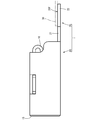
- the main body portion 10 is a rectangular tube-shaped portion that is open at both ends, and includes a bottom wall portion 11, a pair of side wall portions 12A and 12B, and a top wall portion 13, as shown in FIG.
- the bottom wall portion 11 is an elongated rectangular plate-like portion as a whole.
- Each of the pair of side wall portions 12 ⁇ / b> A and 12 ⁇ / b> B is an elongated rectangular plate-like portion that rises perpendicularly to the bottom wall portion 11 from each of the two long sides of the bottom wall portion 11.
- the two side wall portions 12A and 12B are arranged to face each other.
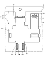
- the first plating region 16M is plated with the same plating material (Ag).
- the second plating region 18M exist on the same surface, and the third plating region 20M plated with a different plating material (Sn) exists on a different surface. Therefore, it is sufficient to perform Ag plating on one surface of the metal plate 50 that is a base material of the terminal fitting 1 and Sn plating on the other surface. Thereby, it can avoid that the process of plating is complicated, and an increase in manufacturing cost can be avoided.
Abstract
La pièce métallique pour borne (1) de l'invention est équipée : d'une partie corps principal (10) constitué d'un matériau en plaque prenant une forme de tube carré; d'une pièce de contact élastique (16) disposée dans une partie interne de la partie corps principal (10); et d'une pièce réceptrice de pression (18) disposée dans la partie interne de la partie corps principal (10) en vis-à-vis avec la pièce de contact élastique (16). La pièce de contact élastique (16) prend une forme de plaque équipée d'une partie extrémité de base (16Eb) courbée depuis un bord extrémité de la partie corps principal (10) vers le côté interne de cette dernière. La pièce réceptrice de pression (18) prend une forme de plaque possédant à une extrémité une partie extrémité de base (18Eb) courbée depuis le bord extrémité de la partie corps principal (10) vers le côté interne de cette dernière. La pièce de contact élastique (16) est telle qu'une région en contact avec une partie onglet (41) au niveau d'une première face de vis-à-vis (16F), constitue une première région placage (16M) sur laquelle est exécuté un placage Ag. Enfin, la pièce réceptrice de pression (18) est telle qu'une région en contact avec la partie onglet (41) au niveau d'une seconde face de vis-à-vis (18F), constitue une seconde région placage (18M) sur laquelle est exécuté un placage Ag.
Priority Applications (4)
| Application Number | Priority Date | Filing Date | Title |
|---|---|---|---|
| JP2018516932A JP6540890B2 (ja) | 2016-05-12 | 2017-04-26 | 端子金具 |
| CN201780026216.7A CN109155479A (zh) | 2016-05-12 | 2017-04-26 | 端子零件 |
| US16/097,848 US10476190B2 (en) | 2016-05-12 | 2017-04-27 | Terminal fitting |
| US16/560,190 US10847913B2 (en) | 2016-05-12 | 2019-09-04 | Terminal fitting |
Applications Claiming Priority (2)
| Application Number | Priority Date | Filing Date | Title |
|---|---|---|---|
| JP2016095876 | 2016-05-12 | ||
| JP2016-095876 | 2016-05-12 |
Related Child Applications (2)
| Application Number | Title | Priority Date | Filing Date |
|---|---|---|---|
| US16/097,848 A-371-Of-International US10476190B2 (en) | 2016-05-12 | 2017-04-27 | Terminal fitting |
| US16/560,190 Division US10847913B2 (en) | 2016-05-12 | 2019-09-04 | Terminal fitting |
Publications (1)
| Publication Number | Publication Date |
|---|---|
| WO2017195595A1 true WO2017195595A1 (fr) | 2017-11-16 |
Family
ID=60266472
Family Applications (1)
| Application Number | Title | Priority Date | Filing Date |
|---|---|---|---|
| PCT/JP2017/016478 WO2017195595A1 (fr) | 2016-05-12 | 2017-04-26 | Pièce métallique pour borne |
Country Status (4)
| Country | Link |
|---|---|
| US (2) | US10476190B2 (fr) |
| JP (2) | JP6540890B2 (fr) |
| CN (1) | CN109155479A (fr) |
| WO (1) | WO2017195595A1 (fr) |
Cited By (1)
| Publication number | Priority date | Publication date | Assignee | Title |
|---|---|---|---|---|
| WO2022264955A1 (fr) * | 2021-06-15 | 2022-12-22 | 株式会社オートネットワーク技術研究所 | Raccord de borne et borne de chaîne |
Citations (3)
| Publication number | Priority date | Publication date | Assignee | Title |
|---|---|---|---|---|
| JP2012243542A (ja) * | 2011-05-19 | 2012-12-10 | Sumitomo Wiring Syst Ltd | 端子金具 |
| JP2012256579A (ja) * | 2011-05-19 | 2012-12-27 | Sumitomo Wiring Syst Ltd | 端子金具及びコネクタ |
| JP2014035959A (ja) * | 2012-08-09 | 2014-02-24 | Auto Network Gijutsu Kenkyusho:Kk | 多接点型雌端子 |
Family Cites Families (20)
| Publication number | Priority date | Publication date | Assignee | Title |
|---|---|---|---|---|
| JP3465876B2 (ja) * | 1999-01-27 | 2003-11-10 | 同和鉱業株式会社 | 耐摩耗性銅または銅基合金とその製造方法ならびに該耐摩耗性銅または銅基合金からなる電気部品 |
| JP3767506B2 (ja) | 2002-04-03 | 2006-04-19 | 住友電装株式会社 | 雌側端子金具 |
| AU2003222669A1 (en) * | 2002-04-22 | 2003-11-03 | Yazaki Corporation | Electrical connectors incorporating low friction coatings and methods for making them |
| EP2173012B1 (fr) * | 2007-06-29 | 2019-04-17 | The Furukawa Electric Co., Ltd. | Connecteur résistant à l'usure et procédé de fabrication correspondant |
| JP2010027453A (ja) * | 2008-07-22 | 2010-02-04 | Hitachi Cable Ltd | 圧着端子付ケーブルおよびその製造方法 |
| JP5246503B2 (ja) * | 2009-02-23 | 2013-07-24 | 住友電装株式会社 | 端子金具 |
| JP5186528B2 (ja) * | 2010-04-23 | 2013-04-17 | 日本発條株式会社 | 導電部材及びその製造方法 |
| DE102011088793A1 (de) * | 2011-12-16 | 2013-06-20 | Tyco Electronics Amp Gmbh | Elektrischer Steckverbinder mit mikrostrukturiertem Kontaktelement |
| TWI493798B (zh) * | 2012-02-03 | 2015-07-21 | Jx Nippon Mining & Metals Corp | Push-in terminals and electronic parts for their use |
| WO2014017614A1 (fr) * | 2012-07-25 | 2014-01-30 | 矢崎総業株式会社 | Fil électrique doté d'une borne et faisceau électrique utilisant celui-ci |
| JP5692192B2 (ja) * | 2012-09-21 | 2015-04-01 | 株式会社オートネットワーク技術研究所 | コネクタ端子の製造方法およびコネクタ端子用材料の製造方法 |
| US9627790B2 (en) * | 2012-10-04 | 2017-04-18 | Fci Americas Technology Llc | Electrical contact including corrosion-resistant coating |
| EP2960999B1 (fr) * | 2013-02-22 | 2018-03-21 | Furukawa Electric Co., Ltd. | Borne, structure de connexion de câblage et procédé de fabrication de borne |
| WO2014199837A1 (fr) * | 2013-06-11 | 2014-12-18 | 株式会社Kanzacc | Structure de borne de contact |
| WO2015083547A1 (fr) * | 2013-12-04 | 2015-06-11 | 株式会社オートネットワーク技術研究所 | Contact électrique et paire de bornes de connecteur |
| JP6490663B2 (ja) * | 2014-03-05 | 2019-03-27 | 古河電気工業株式会社 | 端子及び端子の製造方法 |
| DE102014117410B4 (de) * | 2014-11-27 | 2019-01-03 | Heraeus Deutschland GmbH & Co. KG | Elektrisches Kontaktelement, Einpressstift, Buchse und Leadframe |
| JP6497293B2 (ja) * | 2015-10-20 | 2019-04-10 | 株式会社オートネットワーク技術研究所 | 端子用金属板、端子及び端子対 |
| DE202017001425U1 (de) * | 2016-03-18 | 2017-07-06 | Apple Inc. | Kontakte aus Edelmetallegierungen |
| JP2018120698A (ja) * | 2017-01-24 | 2018-08-02 | 矢崎総業株式会社 | 端子用めっき材並びにそれを用いた端子、端子付き電線及びワイヤーハーネス |
-
2017
- 2017-04-26 WO PCT/JP2017/016478 patent/WO2017195595A1/fr active Application Filing
- 2017-04-26 CN CN201780026216.7A patent/CN109155479A/zh active Pending
- 2017-04-26 JP JP2018516932A patent/JP6540890B2/ja not_active Expired - Fee Related
- 2017-04-27 US US16/097,848 patent/US10476190B2/en not_active Expired - Fee Related
-
2019
- 2019-06-13 JP JP2019110217A patent/JP6819726B2/ja active Active
- 2019-09-04 US US16/560,190 patent/US10847913B2/en active Active
Patent Citations (3)
| Publication number | Priority date | Publication date | Assignee | Title |
|---|---|---|---|---|
| JP2012243542A (ja) * | 2011-05-19 | 2012-12-10 | Sumitomo Wiring Syst Ltd | 端子金具 |
| JP2012256579A (ja) * | 2011-05-19 | 2012-12-27 | Sumitomo Wiring Syst Ltd | 端子金具及びコネクタ |
| JP2014035959A (ja) * | 2012-08-09 | 2014-02-24 | Auto Network Gijutsu Kenkyusho:Kk | 多接点型雌端子 |
Cited By (1)
| Publication number | Priority date | Publication date | Assignee | Title |
|---|---|---|---|---|
| WO2022264955A1 (fr) * | 2021-06-15 | 2022-12-22 | 株式会社オートネットワーク技術研究所 | Raccord de borne et borne de chaîne |
Also Published As
| Publication number | Publication date |
|---|---|
| US10476190B2 (en) | 2019-11-12 |
| JPWO2017195595A1 (ja) | 2018-10-18 |
| US10847913B2 (en) | 2020-11-24 |
| CN109155479A (zh) | 2019-01-04 |
| JP6819726B2 (ja) | 2021-01-27 |
| US20190393636A1 (en) | 2019-12-26 |
| JP6540890B2 (ja) | 2019-07-10 |
| JP2019153599A (ja) | 2019-09-12 |
| US20190148863A1 (en) | 2019-05-16 |
Similar Documents
| Publication | Publication Date | Title |
|---|---|---|
| JP6437276B2 (ja) | コネクタ | |
| US4175821A (en) | Electrical connector | |
| JP5601926B2 (ja) | 圧着端子 | |
| US6752669B2 (en) | Male terminal fitting and method of manufacturing the same | |
| CN103828128A (zh) | 阴端子 | |
| JP6820290B2 (ja) | 接続端子及び端子接続構造 | |
| US9431721B2 (en) | Contact element | |
| JP2013537697A (ja) | 雄電気端子 | |
| JP2022093147A (ja) | 端子ユニット | |
| CN101689713B (zh) | 阳电端子 | |
| JP4132618B2 (ja) | 端子金具のタブ | |
| WO2017195595A1 (fr) | Pièce métallique pour borne | |
| US20220399670A1 (en) | Terminal connection structure | |
| JP2002025674A (ja) | 接続端子 | |
| JP4805729B2 (ja) | 端子金具同士の固定方法及び端子金具 | |
| JP2010010000A (ja) | 端子金具及び端子付き電線 | |
| JP7435362B2 (ja) | 端子金具および連鎖端子 | |
| JP5601925B2 (ja) | 圧着端子 | |
| KR101608375B1 (ko) | 비드부를 구비한 피메일 단자 | |
| JP2020071908A (ja) | 圧着接続端子 | |
| WO2010004825A1 (fr) | Cosse de borne et fil électrique à borne | |
| JP7215933B2 (ja) | 接続端子 | |
| JP7360310B2 (ja) | コンタクトおよびコネクタ | |
| JP2018045886A (ja) | コネクタユニット | |
| JP2015103410A (ja) | 接続端子 |
Legal Events
| Date | Code | Title | Description |
|---|---|---|---|
| ENP | Entry into the national phase |
Ref document number: 2018516932 Country of ref document: JP Kind code of ref document: A |
|
| NENP | Non-entry into the national phase |
Ref country code: DE |
|
| 121 | Ep: the epo has been informed by wipo that ep was designated in this application |
Ref document number: 17795956 Country of ref document: EP Kind code of ref document: A1 |
|
| 122 | Ep: pct application non-entry in european phase |
Ref document number: 17795956 Country of ref document: EP Kind code of ref document: A1 |