WO2017195595A1 - Terminal fitting - Google Patents
Terminal fitting Download PDFInfo
- Publication number
- WO2017195595A1 WO2017195595A1 PCT/JP2017/016478 JP2017016478W WO2017195595A1 WO 2017195595 A1 WO2017195595 A1 WO 2017195595A1 JP 2017016478 W JP2017016478 W JP 2017016478W WO 2017195595 A1 WO2017195595 A1 WO 2017195595A1
- Authority
- WO
- WIPO (PCT)
- Prior art keywords
- plating
- main body
- region
- terminal fitting
- piece
- Prior art date
Links
Images


Classifications
-
- H—ELECTRICITY
- H01—ELECTRIC ELEMENTS
- H01R—ELECTRICALLY-CONDUCTIVE CONNECTIONS; STRUCTURAL ASSOCIATIONS OF A PLURALITY OF MUTUALLY-INSULATED ELECTRICAL CONNECTING ELEMENTS; COUPLING DEVICES; CURRENT COLLECTORS
- H01R13/00—Details of coupling devices of the kinds covered by groups H01R12/70 or H01R24/00 - H01R33/00
- H01R13/02—Contact members
- H01R13/03—Contact members characterised by the material, e.g. plating, or coating materials
-
- H—ELECTRICITY
- H01—ELECTRIC ELEMENTS
- H01R—ELECTRICALLY-CONDUCTIVE CONNECTIONS; STRUCTURAL ASSOCIATIONS OF A PLURALITY OF MUTUALLY-INSULATED ELECTRICAL CONNECTING ELEMENTS; COUPLING DEVICES; CURRENT COLLECTORS
- H01R13/00—Details of coupling devices of the kinds covered by groups H01R12/70 or H01R24/00 - H01R33/00
- H01R13/02—Contact members
- H01R13/10—Sockets for co-operation with pins or blades
- H01R13/11—Resilient sockets
-
- H—ELECTRICITY
- H01—ELECTRIC ELEMENTS
- H01R—ELECTRICALLY-CONDUCTIVE CONNECTIONS; STRUCTURAL ASSOCIATIONS OF A PLURALITY OF MUTUALLY-INSULATED ELECTRICAL CONNECTING ELEMENTS; COUPLING DEVICES; CURRENT COLLECTORS
- H01R13/00—Details of coupling devices of the kinds covered by groups H01R12/70 or H01R24/00 - H01R33/00
- H01R13/40—Securing contact members in or to a base or case; Insulating of contact members
- H01R13/42—Securing in a demountable manner
-
- H—ELECTRICITY
- H01—ELECTRIC ELEMENTS
- H01R—ELECTRICALLY-CONDUCTIVE CONNECTIONS; STRUCTURAL ASSOCIATIONS OF A PLURALITY OF MUTUALLY-INSULATED ELECTRICAL CONNECTING ELEMENTS; COUPLING DEVICES; CURRENT COLLECTORS
- H01R13/00—Details of coupling devices of the kinds covered by groups H01R12/70 or H01R24/00 - H01R33/00
- H01R13/02—Contact members
- H01R13/10—Sockets for co-operation with pins or blades
- H01R13/11—Resilient sockets
- H01R13/113—Resilient sockets co-operating with pins or blades having a rectangular transverse section
-
- H—ELECTRICITY
- H01—ELECTRIC ELEMENTS
- H01R—ELECTRICALLY-CONDUCTIVE CONNECTIONS; STRUCTURAL ASSOCIATIONS OF A PLURALITY OF MUTUALLY-INSULATED ELECTRICAL CONNECTING ELEMENTS; COUPLING DEVICES; CURRENT COLLECTORS
- H01R4/00—Electrically-conductive connections between two or more conductive members in direct contact, i.e. touching one another; Means for effecting or maintaining such contact; Electrically-conductive connections having two or more spaced connecting locations for conductors and using contact members penetrating insulation
- H01R4/02—Soldered or welded connections
- H01R4/029—Welded connections
-
- H—ELECTRICITY
- H01—ELECTRIC ELEMENTS
- H01R—ELECTRICALLY-CONDUCTIVE CONNECTIONS; STRUCTURAL ASSOCIATIONS OF A PLURALITY OF MUTUALLY-INSULATED ELECTRICAL CONNECTING ELEMENTS; COUPLING DEVICES; CURRENT COLLECTORS
- H01R43/00—Apparatus or processes specially adapted for manufacturing, assembling, maintaining, or repairing of line connectors or current collectors or for joining electric conductors
- H01R43/16—Apparatus or processes specially adapted for manufacturing, assembling, maintaining, or repairing of line connectors or current collectors or for joining electric conductors for manufacturing contact members, e.g. by punching and by bending
Definitions
- the terminal fitting includes a plate-like connection portion that extends from one of the two end edges of the cylinder in the main body portion toward the outside of the main body portion, and to which the conductive member is connected.
- the connection portion has a connection surface to which the conductive member is connected, and a region in contact with the conductive member on the connection surface is made of a plating material different from the first plating region and the second plating region. It may be the third plating region where plating is applied.
- the main body portion 10 is a rectangular tube-shaped portion that is open at both ends, and includes a bottom wall portion 11, a pair of side wall portions 12A and 12B, and a top wall portion 13, as shown in FIG.
- the bottom wall portion 11 is an elongated rectangular plate-like portion as a whole.
- Each of the pair of side wall portions 12 ⁇ / b> A and 12 ⁇ / b> B is an elongated rectangular plate-like portion that rises perpendicularly to the bottom wall portion 11 from each of the two long sides of the bottom wall portion 11.
- the two side wall portions 12A and 12B are arranged to face each other.
- the first plating region 16M is plated with the same plating material (Ag).
- the second plating region 18M exist on the same surface, and the third plating region 20M plated with a different plating material (Sn) exists on a different surface. Therefore, it is sufficient to perform Ag plating on one surface of the metal plate 50 that is a base material of the terminal fitting 1 and Sn plating on the other surface. Thereby, it can avoid that the process of plating is complicated, and an increase in manufacturing cost can be avoided.
Landscapes
- Manufacturing Of Electrical Connectors (AREA)
Abstract
This terminal fitting 1 is provided with: a main body 10 comprising a plate material formed into a rectangular tube; an elastic contact piece 16 arranged inside of the main body 10; and a pressure receiving piece 18 which is arranged opposite the elastic contact piece 16 inside of the main body 10. The elastic contact piece 16 has a plate shape having a base end 16Eb which curves from the edge of the main body 10 towards the inside of the main body 10, and the pressure receiving piece 18 has a plate shape having, at one end, a base end 18Eb that curves from the edge of the main body 10 towards the inside of the main body 10. In the elastic contact piece 16, the region that contacts a tab unit 41 on a first facing surface 16F is a first plated region 16M that has been subjected to Ag plating. Further, in the pressure receiving piece 18, the region that contacts the tab unit 41 on a second facing surface 18F is a second plated region 18M that has been subjected to Ag plating.
Description
本明細書によって開示される技術は、端子金具に関する。
The technology disclosed in this specification relates to a terminal fitting.
従来、弾性接触片を備えた雌端子金具が知られている。この雌端子金具は、相手側である雄端子金具のタブ部を受け入れ可能な角筒状の本体部と、この本体部の底壁の前端から突出した舌片を後方へ折り返すことで構成された板バネ状の弾性接触片とを備えている。一方、本体部において弾性接触片と対向する壁部には、弾性接触片に向かって膨出する受け部が設けられている。接点部と受け部とでタブを挟み付けて保持することにより、雌端子金具と雄端子金具との電気的接続が図られる(特許文献1参照)。
上記のような端子金具は、金属板材を所定の形状に打ち抜いて得られた端子金具片を曲げ加工することによって製造されることが一般的である。 Conventionally, a female terminal fitting provided with an elastic contact piece is known. This female terminal fitting is configured by folding back a rectangular tube-shaped main body portion that can receive the tab portion of the mating male terminal fitting, and a tongue protruding from the front end of the bottom wall of the main body portion. And a leaf spring-like elastic contact piece. On the other hand, a receiving portion that bulges toward the elastic contact piece is provided on the wall portion facing the elastic contact piece in the main body. By sandwiching and holding the tab between the contact portion and the receiving portion, electrical connection between the female terminal fitting and the male terminal fitting is achieved (see Patent Document 1).
The terminal fitting as described above is generally manufactured by bending a terminal fitting piece obtained by punching a metal plate material into a predetermined shape.
上記のような雌端子金具において、弾性接触片と受け部とには、接触抵抗の低減を目的として、タブ部と接触する面にAgメッキが施されていることが好ましい。
In the female terminal fitting as described above, it is preferable that the elastic contact piece and the receiving portion are Ag-plated on the surface in contact with the tab portion for the purpose of reducing contact resistance.
しかし、上記のような構成の端子金具(一例を端子金具100として図6に示す)では、メッキを施すべき領域が、この端子金具100の展開状態(曲げ加工前の端子金具片152の状態)において、表裏両面に分散して存在している。すなわち、図7および図8に示すように、弾性接触片116となる部分(弾性素片154)においてAgメッキを施すべき領域が、表裏両面のうち一面(図8の表面)に存在しているのに対し、受け部119においてAgメッキを施すべき領域が他面(図7の表面)に存在することとなる。このため、メッキの工程が複雑化し、製造コストが上昇するという問題があった。
However, in the terminal fitting configured as described above (an example shown in FIG. 6 as the terminal fitting 100), the region to be plated is the developed state of the terminal fitting 100 (the state of the terminal fitting piece 152 before bending). In the present invention, it is dispersed on both sides. That is, as shown in FIGS. 7 and 8, a region to be subjected to Ag plating in the portion (elastic element piece 154) that becomes the elastic contact piece 116 exists on one side (the surface in FIG. 8) of the front and back sides. On the other hand, the region to be subjected to Ag plating in the receiving portion 119 exists on the other surface (the surface in FIG. 7). For this reason, there is a problem that the plating process becomes complicated and the manufacturing cost increases.
本明細書によって開示される端子金具は、筒状とされた板材からなり、内部に相手側の端子金具を受け入れ可能な本体部と、前記本体部の内部に配置され、前記相手側の端子金具に弾性的に接触する弾性接触片と、前記本体部の内部に前記弾性接触片と対向して配置され、前記弾性接触片との間で前記相手側の端子金具を挟み付ける受圧片とを備え、前記弾性接触片が、前記本体部における筒の両端縁のうちいずれかの端縁から前記本体部の内側に向かって湾曲する第1の折り返し部を一端に有する板状であり、前記受圧片が、前記本体部における筒の両端縁のうちいずれかの端縁から前記本体部の内側に向かって湾曲する第2の折り返し部を一端に有する板状であり、前記弾性接触片が、前記受圧片と対向する第1対向面を有しており、前記第1対向面において前記相手側の端子金具と接触する領域が、メッキが施された第1メッキ領域となっており、前記受圧片が、前記弾性接触片と対向する第2対向面を有しており、前記第2対向面において前記相手側の端子金具と接触する領域が、前記第1メッキ領域と同一のメッキ材料によりメッキが施された第2メッキ領域となっている。
The terminal fitting disclosed in the present specification is made of a plate material having a cylindrical shape, and has a main body portion that can receive the mating terminal fitting inside, and is disposed inside the main body portion, and the mating terminal fitting. An elastic contact piece that elastically contacts the pressure contact piece, and a pressure receiving piece that is disposed inside the main body portion so as to face the elastic contact piece and sandwich the mating terminal fitting with the elastic contact piece. The elastic contact piece has a plate-like shape having a first folded portion bent at one end from one end edge of the cylinder in the main body portion toward the inside of the main body portion, and the pressure receiving piece Is a plate having at one end a second folded portion that curves from one of the two end edges of the cylinder in the main body toward the inside of the main body, and the elastic contact piece is the pressure receiving member. A first facing surface facing the piece; The region of the first opposing surface that contacts the mating terminal fitting is a plated first plated region, and the pressure receiving piece has a second opposing surface that faces the elastic contact piece. In addition, a region in contact with the mating terminal fitting on the second facing surface is a second plating region plated with the same plating material as the first plating region.
上記の構成によれば、端子金具の展開状態(曲げ加工する前の端子金具片の状態)では、同一のメッキ材料によりメッキが施される第1メッキ領域と第2メッキ領域とが、同じ面に存在することとなる。これにより、メッキを施す工程が複雑化することを回避することができ、製造コストの上昇を回避することができる。
According to said structure, in the expansion | deployment state (state of the terminal metal piece piece before a bending process) of a terminal metal fitting, the 1st plating area | region and the 2nd plating area | region plated by the same plating material are the same surfaces. Will exist. Thereby, it can avoid that the process of plating is complicated, and an increase in manufacturing cost can be avoided.
上記の構成において、端子金具が、前記本体部における筒の両端縁のうちいずれかの端縁から前記本体部の外側に向かって延び、導電性部材が接続される板状の接続部を備え、前記接続部が、前記導電性部材が接続される接続面を有し、前記接続面において前記導電性部材と接触する領域が、前記第1メッキ領域および前記第2メッキ領域とは異なるメッキ材料によってメッキが施された第3メッキ領域となっていても構わない。
In the above configuration, the terminal fitting includes a plate-like connection portion that extends from one of the two end edges of the cylinder in the main body portion toward the outside of the main body portion, and to which the conductive member is connected. The connection portion has a connection surface to which the conductive member is connected, and a region in contact with the conductive member on the connection surface is made of a plating material different from the first plating region and the second plating region. It may be the third plating region where plating is applied.
上記の構成によれば、端子金具の展開状態(端子金具片の状態)で、第1、第2メッキ領域とは異なるメッキ材料によってメッキが施される第3メッキ領域とが、第1、第2メッキ領域とは異なる面に存在することとなる。これにより、メッキを施す工程が複雑化することを回避することができ、製造コストの上昇を回避することができる。
According to said structure, in the expansion | deployment state (state of a terminal metal piece piece) of a terminal metal fitting, the 3rd plating area | region plated by the plating material different from a 1st, 2nd plating area | region is 1st, 1st. It exists on a different surface from the 2-plated region. Thereby, it can avoid that the process of plating is complicated, and an increase in manufacturing cost can be avoided.
本明細書によって開示される端子金具によれば、メッキを施す工程が複雑化することを回避でき、製造コストの上昇を回避できる。
According to the terminal fitting disclosed in this specification, it is possible to avoid a complicated plating process and to avoid an increase in manufacturing cost.
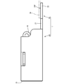
実施形態を図1~図5を参照しつつ説明する。本実施形態の端子金具1は、雄端子金具40(相手側の端子金具に該当)と接続される雌型の端子金具であって、金属板材50を図4に示す形状に打ち抜き加工して得た端子金具片52を曲げ加工して形成される。この端子金具1は、図1に示すように、内部に雄端子金具40のタブ部41を受け入れる本体部10と、この本体部10から連なる接続部20とを備えている。
Embodiments will be described with reference to FIGS. The terminal fitting 1 of this embodiment is a female terminal fitting connected to the male terminal fitting 40 (corresponding to the mating terminal fitting), and is obtained by punching a metal plate material 50 into the shape shown in FIG. The terminal fitting piece 52 is formed by bending. As shown in FIG. 1, the terminal fitting 1 includes a main body portion 10 that receives a tab portion 41 of a male terminal fitting 40 and a connection portion 20 that continues from the main body portion 10.
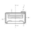
本体部10は、両端が開口した角筒状の部分であって、図2に示すように、底壁部11と、一対の側壁部12A、12Bと、天壁部13とを備えている。底壁部11は、全体として細長い長方形の板状の部分である。一対の側壁部12A、12Bのそれぞれは、底壁部11の2つの長辺のそれぞれから、底壁部11に対して垂直に立ち上がる、全体として細長い長方形の板状の部分である。2つの側壁部12A、12Bは、互いに向かい合って配置されている。天壁部13は、底壁部11に対向して配置される、細長い長方形の板状の部分であって、一方の側壁部12Aから連なり、他方の側壁部12Bに向かって延びている。なお、天壁部13の外側面には、他方の側壁部12Bから連なり、一方の側壁部12Aに向かって延びる係止壁14が重なって配置されている。
本体部10の両端の開口部のうち一方の開口部は、タブ部41が挿入される端子挿入口15となっている。 Themain body portion 10 is a rectangular tube-shaped portion that is open at both ends, and includes a bottom wall portion 11, a pair of side wall portions 12A and 12B, and a top wall portion 13, as shown in FIG. The bottom wall portion 11 is an elongated rectangular plate-like portion as a whole. Each of the pair of side wall portions 12 </ b> A and 12 </ b> B is an elongated rectangular plate-like portion that rises perpendicularly to the bottom wall portion 11 from each of the two long sides of the bottom wall portion 11. The two side wall portions 12A and 12B are arranged to face each other. The top wall portion 13 is an elongated rectangular plate-like portion disposed to face the bottom wall portion 11, is continuous from one side wall portion 12 </ b> A, and extends toward the other side wall portion 12 </ b> B. In addition, the locking wall 14 which continues from the other side wall part 12B and extends toward the one side wall part 12A overlaps with the outer side surface of the top wall part 13.
One of the openings at both ends of themain body 10 is a terminal insertion opening 15 into which the tab 41 is inserted.
本体部10の両端の開口部のうち一方の開口部は、タブ部41が挿入される端子挿入口15となっている。 The
One of the openings at both ends of the
本体部10の内部には、弾性接触片16と受圧片18とが配されている。
弾性接触片16は、図3に示すように、本体部10の内部に配置され、天壁部13に沿って延びる板バネ状の部分である。この弾性接触片16は、一端が、天壁部13において端子挿入口15とは反対側の端縁から、本体部10の内側に向かって折り返されるように湾曲する基端部16Eb(第1の折り返し部に該当)となっており、他端部が自由端部16Efとなっている。 Anelastic contact piece 16 and a pressure receiving piece 18 are arranged inside the main body 10.
As shown in FIG. 3, theelastic contact piece 16 is a leaf spring-like portion that is disposed inside the main body portion 10 and extends along the top wall portion 13. The elastic contact piece 16 has a base end portion 16Eb (first end) that is bent so that one end of the elastic contact piece 16 is folded toward the inside of the main body portion 10 from the end edge of the top wall portion 13 opposite to the terminal insertion port 15. The other end is a free end 16Ef.
弾性接触片16は、図3に示すように、本体部10の内部に配置され、天壁部13に沿って延びる板バネ状の部分である。この弾性接触片16は、一端が、天壁部13において端子挿入口15とは反対側の端縁から、本体部10の内側に向かって折り返されるように湾曲する基端部16Eb(第1の折り返し部に該当)となっており、他端部が自由端部16Efとなっている。 An
As shown in FIG. 3, the
弾性接触片16は、基端部16Ebに近い側の大部分が、基端部16Ebから離れるに従って緩やかに天壁部13から離れ、自由端部16Efに近い残りの部分が自由端部16Efに近づくにつれて緩やかに天壁部13に近づく山状をなしている。山の頂点部分には、底壁部11に向かってドーム状に膨出し、タブ部41に接触する接点部17が配置されている。
Most of the elastic contact piece 16 on the side close to the base end portion 16Eb is gradually separated from the top wall portion 13 as it is away from the base end portion 16Eb, and the remaining portion close to the free end portion 16Ef is close to the free end portion 16Ef. As a result, it forms a mountain shape that gradually approaches the top wall 13. A contact portion 17 that bulges in a dome shape toward the bottom wall portion 11 and contacts the tab portion 41 is disposed at the apex portion of the mountain.
受圧片18は、図3に示すように、本体部10の内部に、底壁部11に当接し、弾性接触片16と対向して配置される板状の部分であって、一端が、底壁部11において端子挿入口15の開口縁を構成する端縁から、本体部10の内側に向かって折り返されるように湾曲する基端部18Eb(第2の折り返し部に該当)とされている。受圧片18は、接点部17との間でタブ部41を挟み付けてタブ部41との接触圧を確保するための2つの接触凸部19を有している。各接触凸部19は、受圧片18の一部分(接点部17と対向する部分)が弾性接触片16に向かってドーム状に膨出した部分である。
As shown in FIG. 3, the pressure receiving piece 18 is a plate-like portion disposed inside the main body portion 10 so as to abut against the bottom wall portion 11 and to face the elastic contact piece 16, and has one end at the bottom. A base end portion 18Eb (corresponding to a second folded portion) that curves so as to be folded back toward the inside of the main body portion 10 from an end edge constituting the opening edge of the terminal insertion port 15 in the wall portion 11 is used. The pressure receiving piece 18 has two contact convex portions 19 for sandwiching the tab portion 41 between the contact portion 17 and securing a contact pressure with the tab portion 41. Each contact convex portion 19 is a portion in which a part of the pressure receiving piece 18 (a portion facing the contact portion 17) bulges toward the elastic contact piece 16 in a dome shape.
弾性接触片16において受圧片18と対向する面は、第1対向面16Fとなっており、この第1対向面16Fにおいて、接点部17が配置されている領域は、タブ部41と接触する第1メッキ領域16Mとなっている(図5において網掛けで示す)。また、受圧片18において弾性接触片16と対向する面は、第2対向面18Fとなっており、この第2対向面18Fにおいて、2つの接触凸部19が配置されている領域は、タブ部41と接触する第2メッキ領域18Mとなっている(図5において網掛けで示す)。
A surface of the elastic contact piece 16 that faces the pressure receiving piece 18 is a first facing surface 16F, and a region where the contact portion 17 is disposed on the first facing surface 16F is in contact with the tab portion 41. 1 plating region 16M (shown by hatching in FIG. 5). Further, the surface of the pressure receiving piece 18 that faces the elastic contact piece 16 is a second facing surface 18F, and the region where the two contact convex portions 19 are arranged on the second facing surface 18F is a tab portion. The second plating region 18M is in contact with 41 (shown by hatching in FIG. 5).
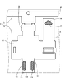
接続部20は、図1に示すように、底壁部11において端子挿入口15とは反対側の端縁から延びる平板状の部分であって、底壁部11と同一平面上に延びている。この接続部20は、底壁部11から連なる連結部21と、この連結部21から連なり、連結部21より幅広の固着部22を有している。固着部22は、可撓性および導電性を有する接続部材30(導電性部材に該当;例えば編組)が、抵抗溶接によって接続される部分である。接続部20において、底壁部11の内側面と同じ側を向く面(図1の上面)は接続面20Fとなっており、接続部材30は、この接続面20Fに接続される。接続面20Fのうち、固着部22が配置されている領域が、第3メッキ領域20Mとなっている(図4に網掛けで示す)。
As shown in FIG. 1, the connecting portion 20 is a flat plate-like portion extending from the end edge of the bottom wall portion 11 opposite to the terminal insertion port 15, and extends on the same plane as the bottom wall portion 11. . The connecting portion 20 includes a connecting portion 21 that continues from the bottom wall portion 11 and a fixing portion 22 that extends from the connecting portion 21 and is wider than the connecting portion 21. The fixing portion 22 is a portion to which a connection member 30 (corresponding to a conductive member; for example, a braid) having flexibility and conductivity is connected by resistance welding. In the connection part 20, the surface (upper surface in FIG. 1) facing the same side as the inner surface of the bottom wall part 11 is a connection surface 20F, and the connection member 30 is connected to the connection surface 20F. In the connection surface 20F, a region where the fixing portion 22 is disposed is a third plating region 20M (shown by hatching in FIG. 4).
端子金具1は、銅、銅合金などの金属材料からなり、本体部10の外側面、接続部20の接続面20Fとは反対側の面、弾性接触片16の第1対向面16F(第1メッキ領域16Mを含む面)、および、受圧片18の第2対向面18F(第2メッキ領域18Mを含む面)には、全面にAgメッキが施されている。また、本体部10の内側面、接続部20の接続面20F(第3メッキ領域20Mを含む面)、弾性接触片16において第1対向面16Fと反対側の面(天壁部13と対向する面)、および、受圧片18において第2対向面18Fと反対側の面(底壁部11と対向する面)には、全面にSnメッキが施されている。
The terminal fitting 1 is made of a metal material such as copper or copper alloy, the outer surface of the main body 10, the surface opposite to the connection surface 20 </ b> F of the connection portion 20, the first facing surface 16 </ b> F (first surface of the elastic contact piece 16). Ag plating is applied to the entire surface of the surface including the plating region 16M and the second opposing surface 18F of the pressure receiving piece 18 (surface including the second plating region 18M). Further, the inner surface of the main body 10, the connection surface 20 </ b> F (surface including the third plating region 20 </ b> M) of the connection portion 20, and the surface opposite to the first facing surface 16 </ b> F (the top wall portion 13). Surface) and the surface opposite to the second facing surface 18F (the surface facing the bottom wall portion 11) of the pressure receiving piece 18 are plated with Sn.
第3メッキ領域20Mを含む接続面20FにSnメッキが施されていることにより、接続部材30を固着部22に溶接する際の接合品質が確保される。また、第1メッキ領域16Mを含む第1対向面16Fと第2メッキ領域18Mを含む第2対向面18FとにAgメッキが施されていることにより、タブ部41との接続の際の接触抵抗を小さくすることができる。
Since the connection surface 20F including the third plating region 20M is Sn plated, the bonding quality when the connection member 30 is welded to the fixing portion 22 is ensured. Further, the Ag resistance is applied to the first opposing surface 16F including the first plating region 16M and the second opposing surface 18F including the second plating region 18M, so that the contact resistance at the time of connection with the tab portion 41 is achieved. Can be reduced.
上記のように構成された端子金具1の製造方法の一例を、以下に示す。
まず、端子金具1の材料となる金属板材50の表裏両面のうち一面(図4の表面)に、全面にわたってSnメッキを施し、他面(図5の表面)に、全面にわたってAgメッキを施す。 An example of the manufacturing method of the terminal metal fitting 1 comprised as mentioned above is shown below.
First, Sn plating is performed on the entire surface (the surface in FIG. 4) of the front and back surfaces of themetal plate 50 that is the material of the terminal fitting 1, and Ag plating is performed on the entire other surface (the surface in FIG. 5).
まず、端子金具1の材料となる金属板材50の表裏両面のうち一面(図4の表面)に、全面にわたってSnメッキを施し、他面(図5の表面)に、全面にわたってAgメッキを施す。 An example of the manufacturing method of the terminal metal fitting 1 comprised as mentioned above is shown below.
First, Sn plating is performed on the entire surface (the surface in FIG. 4) of the front and back surfaces of the
次に、メッキを施した金属板材50をプレス加工して、図4および図5に示すように、端子金具1となる端子金具片52の複数が、一枚の帯状のキャリア57に連結された連鎖端子51を得る。複数の端子金具片52は、キャリア57の長さ方向に沿って等間隔に並んでいる。
Next, the plated metal plate material 50 was pressed, and a plurality of terminal fitting pieces 52 to be the terminal fittings 1 were connected to a single belt-like carrier 57 as shown in FIGS. A chain terminal 51 is obtained. The plurality of terminal fitting pieces 52 are arranged at equal intervals along the length direction of the carrier 57.
各端子金具片52は、本体部10となる板状の本体素片53と、この本体素片53から延び、弾性接触片16となる弾性素片54と、同じくこの本体素片53から延び、受圧片18となる受圧素片55と、同じくこの本体素片53から延び、接続部20となる接続素片56とを備える、全体として平板状の部分である。弾性素片54には叩き出しによって接点部17が形成され、受圧素片55には叩き出しによって接触凸部19が形成される。
Each terminal metal piece 52 extends from the main body piece 53, a plate-like main body piece 53 to be the main body portion 10, an elastic piece 54 to be the elastic contact piece 16, and the main body piece 53. It is a flat plate-like part as a whole, including a pressure receiving element piece 55 that becomes the pressure receiving piece 18 and a connection element piece 56 that also extends from the main body element 53 and becomes the connection portion 20. The contact point 17 is formed on the elastic piece 54 by knocking out, and the contact convex portion 19 is formed on the pressure receiving piece 55 by knocking out.
弾性素片54において第1対向面16Fとなる面(第1メッキ領域16Mを含む面)と、受圧素片55とにおいて第2対向面18Fとなる面(第2メッキ領域18Mを含む面)とは、いずれも端子金具片52の同じ側の面(Agメッキをが施された面;図5の表面)に配されている。また、接続素片56において接続面20Fとなる面(第3メッキ領域20Mを含む面)は、第1メッキ領域16Mおよび第2メッキ領域18Mを含む面とは反対側の面(Snメッキが施された面;図4の表面)に配されている。
A surface (a surface including the first plating region 16M) serving as the first opposing surface 16F in the elastic piece 54, and a surface (a surface including the second plating region 18M) serving as the second opposing surface 18F in the pressure receiving element piece 55. Are arranged on the same side surface of the terminal fitting piece 52 (surface subjected to Ag plating; surface in FIG. 5). In addition, the surface (the surface including the third plating region 20M) which is the connection surface 20F in the connection element 56 is the surface opposite to the surface including the first plating region 16M and the second plating region 18M (Sn plating is performed). The surface of FIG. 4).
次に、各端子金具片52において、弾性素片54を図4に2点鎖線で示す折り目位置で折り曲げて、本体素片53に沿わせるとともに、弾性接触片16の形状となるように曲げ加工する。また、受圧素片55を図4に2点鎖線で示す折り目位置で折り曲げて、本体素片53に沿わせるようにする。次いで、本体素片53を、図4に2点鎖線で示す折り目位置で折り曲げて角筒状とする。このようにして、内部に弾性接触片16と受圧片18とが配置された本体部10を形成する。
最後に、各端子金具片52をキャリア57から切り離す。このようにして端子金具1が完成する。 Next, in eachterminal metal piece 52, the elastic element piece 54 is bent at a fold position indicated by a two-dot chain line in FIG. 4 so as to be along the main body element piece 53 and bent so as to have the shape of the elastic contact piece 16. To do. Further, the pressure receiving piece 55 is bent at the fold position indicated by a two-dot chain line in FIG. Next, the main body piece 53 is bent into a rectangular tube shape at a crease position indicated by a two-dot chain line in FIG. In this way, the main body 10 is formed in which the elastic contact piece 16 and the pressure receiving piece 18 are disposed.
Finally, eachterminal metal piece 52 is separated from the carrier 57. In this way, the terminal fitting 1 is completed.
最後に、各端子金具片52をキャリア57から切り離す。このようにして端子金具1が完成する。 Next, in each
Finally, each
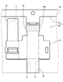
上記のように構成された端子金具1が雄端子金具40と接続される際には、図3に示すように、タブ部41が、端子挿入口15から本体部10の内部に進入し、弾性接触片16の接点部17と当接して、弾性接触片16を天壁部13に向かって押圧する。そして、弾性接触片16からの弾発力によって、タブ部41は、接点部17と、受圧片18の接触凸部19との間に挟み付けられる。これにより端子金具1と雄端子金具40との電気的接続が図られる。
When the terminal fitting 1 configured as described above is connected to the male terminal fitting 40, as shown in FIG. 3, the tab portion 41 enters the inside of the main body portion 10 through the terminal insertion port 15, and is elastic. The elastic contact piece 16 is pressed toward the top wall portion 13 in contact with the contact portion 17 of the contact piece 16. Then, the tab portion 41 is sandwiched between the contact portion 17 and the contact convex portion 19 of the pressure receiving piece 18 by the elastic force from the elastic contact piece 16. Thereby, electrical connection between the terminal fitting 1 and the male terminal fitting 40 is achieved.
以上のように本実施形態によれば、端子金具1は、角筒状とされた板材からなり、内部に雄端子金具40を受け入れ可能な本体部10と、本体部10の内部に配置され、雄端子金具40のタブ部41に弾性的に接触する弾性接触片16と、本体部10の内部に弾性接触片16と対向して配置され、弾性接触片16との間でタブ部41を挟み付ける受圧片18とを備える。弾性接触片16が、端子挿入口15とは反対側の端縁から、本体部10の内側に向かって湾曲する基端部16Ebを備える板状であり、受圧片18が、本体部10における端子挿入口15の開口縁を構成する端縁から本体部10の内側に向かって湾曲する基端部18Ebを有する板状である。そして、弾性接触片16が、受圧片18と対向する第1対向面16Fを有しており、この第1対向面16Fにおいてタブ部41と接触する接点部17が配置されている領域が、Agメッキが施された第1メッキ領域16Mとなっている。また、受圧片18が、弾性接触片16と対向する第2対向面18Fを有しており、この第2対向面18Fにおいて接触凸部19が配置された領域が、Agメッキが施された第2メッキ領域18Mとなっている。
As described above, according to the present embodiment, the terminal fitting 1 is made of a plate material in the shape of a rectangular tube, and is disposed inside the main body 10 that can receive the male terminal fitting 40 inside, The elastic contact piece 16 that elastically contacts the tab portion 41 of the male terminal fitting 40 and the elastic contact piece 16 disposed inside the main body portion 10 so as to face the elastic contact piece 16. And a pressure receiving piece 18 to be attached. The elastic contact piece 16 has a plate shape including a base end portion 16Eb that curves toward the inside of the main body portion 10 from the end opposite to the terminal insertion port 15, and the pressure receiving piece 18 is a terminal in the main body portion 10. It has a plate shape having a base end portion 18Eb that curves from the end edge constituting the opening edge of the insertion port 15 toward the inside of the main body portion 10. And the elastic contact piece 16 has the 1st opposing surface 16F which opposes the pressure receiving piece 18, and the area | region where the contact part 17 which contacts the tab part 41 in this 1st opposing surface 16F is arrange | positioned is Ag. The first plating region 16M is plated. Further, the pressure receiving piece 18 has a second facing surface 18F that faces the elastic contact piece 16, and a region where the contact convex portion 19 is disposed on the second facing surface 18F is the first plated with Ag. 2 plating region 18M.
上記の構成によれば、端子金具1の展開状態(曲げ加工前の端子金具片52の状態)において、同一のメッキ材料であるAgによりメッキが施される第1メッキ領域16Mと第2メッキ領域18Mとが、いずれも同じ面(図5において表面)に配されることとなる。したがって、この端子金具1の基材となる金属板材50の一面にAgメッキを施せば足りる。これにより、メッキを施す工程が複雑化することを回避することができ、製造コストの上昇を回避することができる。
According to said structure, in the expansion | deployment state (state of the terminal metal piece piece 52 before a bending process) of the terminal metal fitting 1, the 1st plating area | region 16M and 2nd plating area | region which are plated with Ag which is the same plating material. 18M are arranged on the same surface (surface in FIG. 5). Therefore, it is sufficient to apply Ag plating to one surface of the metal plate material 50 which is the base material of the terminal fitting 1. Thereby, it can avoid that the process of plating is complicated, and an increase in manufacturing cost can be avoided.
また、端子金具1は、本体部10における端子挿入口15とは反対側の端縁から、本体部10の外側に向かって延びる板状の接続部20を備える。そして、接続部20が、接続部材30が接続される接続面20Fを有しており、この接続面20Fにおいて接続部材30と接触する領域が、第1メッキ領域16Mおよび第2メッキ領域18Mとは異なるメッキ材料であるSnによってメッキが施された第3メッキ領域20Mとなっている。
Further, the terminal fitting 1 includes a plate-like connection portion 20 that extends from the edge of the main body portion 10 opposite to the terminal insertion port 15 toward the outside of the main body portion 10. And the connection part 20 has the connection surface 20F to which the connection member 30 is connected, and the area | region which contacts the connection member 30 in this connection surface 20F is the 1st plating area | region 16M and the 2nd plating area | region 18M. The third plating region 20M is plated with Sn, which is a different plating material.
ここで、本体部110が、底壁部111に設けられた受け部119を有し、受け部119と弾性接触片116との間でタブ部41を挟み付けるようになっている、従来の構成の端子金具100(図6参照)では、弾性接触片116が、タブ部41と対向する第1対向面116Fを有しており、この第1対向面116Fにおいてタブ部41と接触する接点部117が配置されている領域が、Agメッキが施されるべき第1メッキ領域116Mとなる。また、底壁部111の内側面において、受け部119が配置された領域が、Agメッキが施されるべき第2メッキ領域119Mとなる。さらに、接続部120が、接続部材30が接続される接続面120Fを有しており、この接続面120Fにおいて接続部材30と接触する領域が、Snによってメッキが施されるべき第3メッキ領域120Mとなる。
Here, the main body 110 has a receiving portion 119 provided on the bottom wall portion 111, and the tab portion 41 is sandwiched between the receiving portion 119 and the elastic contact piece 116. In the terminal fitting 100 (see FIG. 6), the elastic contact piece 116 has a first facing surface 116F facing the tab portion 41, and the contact portion 117 contacting the tab portion 41 on the first facing surface 116F. The region where the is disposed is the first plating region 116M to be subjected to Ag plating. Further, on the inner side surface of the bottom wall portion 111, a region where the receiving portion 119 is disposed is a second plating region 119M to be subjected to Ag plating. Furthermore, the connection part 120 has a connection surface 120F to which the connection member 30 is connected, and a region in contact with the connection member 30 on the connection surface 120F is a third plating region 120M to be plated with Sn. It becomes.
このような構成の端子金具100では、図7および図8に示すように、展開状態(曲げ加工前の端子金具片152の状態)において、第2メッキ領域119M(Agメッキを施すべき領域)と第3メッキ領域120M(Snメッキを施すべき領域)とが同じ面(図7の表面)に存在しているのに対し、第1メッキ領域116M(Agメッキを施すべき領域)が、その反対側の面(図8の表面)に存在している。したがって、第2メッキ領域119Mと第3メッキ領域120Mとが存在する面についてストライプメッキや部分メッキを行い、さらに、第1メッキ領域116Mが存在する面にメッキを施さねばならず、メッキの工程が複雑化する。
In the terminal fitting 100 having such a configuration, as shown in FIGS. 7 and 8, in the unfolded state (state of the terminal fitting piece 152 before bending), the second plating region 119M (region to be subjected to Ag plating) and The third plating region 120M (region to be subjected to Sn plating) is present on the same surface (the surface in FIG. 7), whereas the first plating region 116M (region to be subjected to Ag plating) is on the opposite side. On the surface (surface of FIG. 8). Therefore, stripe plating or partial plating must be performed on the surface on which the second plating region 119M and the third plating region 120M exist, and further, the surface on which the first plating region 116M exists must be plated. To be complicated.
しかし、本実施形態の構成によれば、端子金具1の展開状態(曲げ加工前の端子金具片52の状態)において、互いに同一のメッキ材料(Ag)によってメッキが施される第1メッキ領域16Mと第2メッキ領域18Mとが同一の面に存在し、これらとは異なるメッキ材料(Sn)によってメッキが施される第3メッキ領域20Mとが、異なる面に存在することとなる。したがって、この端子金具1の基材となる金属板材50の一面にAgメッキを施し、他面にSnメッキを施せば足りる。これにより、メッキを施す工程が複雑化することを回避することができ、製造コストの上昇を回避することができる。
However, according to the configuration of the present embodiment, in the unfolded state of the terminal fitting 1 (the state of the terminal fitting piece 52 before bending), the first plating region 16M is plated with the same plating material (Ag). And the second plating region 18M exist on the same surface, and the third plating region 20M plated with a different plating material (Sn) exists on a different surface. Therefore, it is sufficient to perform Ag plating on one surface of the metal plate 50 that is a base material of the terminal fitting 1 and Sn plating on the other surface. Thereby, it can avoid that the process of plating is complicated, and an increase in manufacturing cost can be avoided.
<他の実施形態>
本明細書によって開示される技術は上記記述及び図面によって説明した実施形態に限定されるものではなく、例えば次のような種々の態様も含まれる。
(1)上記実施形態では、金属板材50にメッキを施してからプレス加工およびプレス加工を行ったが、プレス加工により得られた端子金具片52に対し、曲げ加工を行う前にメッキを施しても構わない。 <Other embodiments>
The technology disclosed in the present specification is not limited to the embodiments described with reference to the above description and drawings, and includes, for example, the following various aspects.
(1) In the above embodiment, themetal plate material 50 is plated and then pressed and pressed. However, the terminal metal piece 52 obtained by pressing is plated before bending. It doesn't matter.
本明細書によって開示される技術は上記記述及び図面によって説明した実施形態に限定されるものではなく、例えば次のような種々の態様も含まれる。
(1)上記実施形態では、金属板材50にメッキを施してからプレス加工およびプレス加工を行ったが、プレス加工により得られた端子金具片52に対し、曲げ加工を行う前にメッキを施しても構わない。 <Other embodiments>
The technology disclosed in the present specification is not limited to the embodiments described with reference to the above description and drawings, and includes, for example, the following various aspects.
(1) In the above embodiment, the
(2)上記実施形態では、金属板材50の一面に全面にわたってSnメッキを施し、他面に、全面にわたってAgメッキを施したが、例えば、金属板材50の一面に、第3メッキ領域を除く領域をマスキング材により被覆した状態でSnメッキを施し、他面に、第1および第2メッキ領域を除く領域をマスキング材により被覆した状態でAgメッキを施しても構わない。
(2) In the above embodiment, Sn plating is performed on the entire surface of the metal plate 50 and Ag plating is performed on the entire surface of the other surface. For example, a region excluding the third plating region is formed on the surface of the metal plate 50. Sn plating may be performed in a state of covering with a masking material, and Ag plating may be performed on a surface other than the first and second plating regions with a masking material on the other surface.
1…端子金具
10…本体部
16…弾性接触片
16Eb…基端部(第1の折り返し部)
16F…第1対向面
16M…第1メッキ領域
18…受圧片
18Eb…基端部(第2の折り返し部)
18F…第2対向面
18M…第2メッキ領域
20…接続部
20F…接続面
20M…第3メッキ領域
30…接続部材(導電性部材)
40…雄端子金具(相手側の端子金具) DESCRIPTION OFSYMBOLS 1 ... Terminal metal fitting 10 ... Main-body part 16 ... Elastic contact piece 16Eb ... Base end part (1st folding | turning part)
16F ...1st opposing surface 16M ... 1st plating area | region 18 ... Pressure receiving piece 18Eb ... Base end part (2nd folding | turning part)
18F ... 2nd opposingsurface 18M ... 2nd plating area | region 20 ... Connection part 20F ... Connection surface 20M ... 3rd plating area | region 30 ... Connection member (conductive member)
40 ... Male terminal fitting (mating terminal fitting)
10…本体部
16…弾性接触片
16Eb…基端部(第1の折り返し部)
16F…第1対向面
16M…第1メッキ領域
18…受圧片
18Eb…基端部(第2の折り返し部)
18F…第2対向面
18M…第2メッキ領域
20…接続部
20F…接続面
20M…第3メッキ領域
30…接続部材(導電性部材)
40…雄端子金具(相手側の端子金具) DESCRIPTION OF
16F ...
18F ... 2nd opposing
40 ... Male terminal fitting (mating terminal fitting)
Claims (2)
- 筒状とされた板材からなり、内部に相手側の端子金具を受け入れ可能な本体部と、
前記本体部の内部に配置され、前記相手側の端子金具に弾性的に接触する弾性接触片と、
前記本体部の内部に前記弾性接触片と対向して配置され、前記弾性接触片との間で前記相手側の端子金具を挟み付ける受圧片とを備え、
前記弾性接触片が、前記本体部における筒の両端縁のうちいずれかの端縁から前記本体部の内側に向かって湾曲する第1の折り返し部を一端に有する板状であり、
前記受圧片が、前記本体部における筒の両端縁のうちいずれかの端縁から前記本体部の内側に向かって湾曲する第2の折り返し部を一端に有する板状であり、
前記弾性接触片が、前記受圧片と対向する第1対向面を有しており、前記第1対向面において前記相手側の端子金具と接触する領域が、メッキが施された第1メッキ領域となっており、
前記受圧片が、前記弾性接触片と対向する第2対向面を有しており、前記第2対向面において前記相手側の端子金具と接触する領域が、前記第1メッキ領域と同一のメッキ材料によりメッキが施された第2メッキ領域となっている端子金具。 It consists of a plate material that has a cylindrical shape, and a main body that can receive the mating terminal fitting inside,
An elastic contact piece disposed inside the main body and elastically contacting the mating terminal fitting;
A pressure receiving piece disposed inside the main body portion so as to face the elastic contact piece, and sandwiching the mating terminal fitting with the elastic contact piece;
The elastic contact piece is a plate having at one end a first folded portion that curves from one of both end edges of the cylinder in the main body portion toward the inside of the main body portion,
The pressure receiving piece has a plate shape having a second folded portion at one end that is curved from one of the two end edges of the cylinder in the main body toward the inside of the main body,
The elastic contact piece has a first facing surface facing the pressure receiving piece, and a region in contact with the mating terminal fitting on the first facing surface is a plated first plated region. And
The pressure receiving piece has a second facing surface facing the elastic contact piece, and a region in contact with the mating terminal fitting on the second facing surface is the same plating material as the first plating region. The terminal metal fitting which becomes the 2nd plating field plated by. - 前記本体部における筒の両端縁のうちいずれかの端縁から前記本体部の外側に向かって延び、導電性部材が接続される板状の接続部を備え、
前記接続部が、前記導電性部材が接続される接続面を有し、前記接続面において前記導電性部材と接触する領域が、前記第1メッキ領域および前記第2メッキ領域とは異なるメッキ材料によってメッキが施された第3メッキ領域となっている、請求項1に記載の端子金具。 A plate-like connecting portion that extends from either end edge of the cylinder in the main body portion toward the outside of the main body portion and to which a conductive member is connected,
The connection portion has a connection surface to which the conductive member is connected, and a region in contact with the conductive member on the connection surface is made of a plating material different from the first plating region and the second plating region. The terminal fitting according to claim 1, wherein the terminal fitting is a third plating region to which plating is applied.
Priority Applications (4)
| Application Number | Priority Date | Filing Date | Title |
|---|---|---|---|
| CN201780026216.7A CN109155479A (en) | 2016-05-12 | 2017-04-26 | terminal part |
| JP2018516932A JP6540890B2 (en) | 2016-05-12 | 2017-04-26 | Terminal bracket |
| US16/097,848 US10476190B2 (en) | 2016-05-12 | 2017-04-27 | Terminal fitting |
| US16/560,190 US10847913B2 (en) | 2016-05-12 | 2019-09-04 | Terminal fitting |
Applications Claiming Priority (2)
| Application Number | Priority Date | Filing Date | Title |
|---|---|---|---|
| JP2016095876 | 2016-05-12 | ||
| JP2016-095876 | 2016-05-12 |
Related Child Applications (2)
| Application Number | Title | Priority Date | Filing Date |
|---|---|---|---|
| US16/097,848 A-371-Of-International US10476190B2 (en) | 2016-05-12 | 2017-04-27 | Terminal fitting |
| US16/560,190 Division US10847913B2 (en) | 2016-05-12 | 2019-09-04 | Terminal fitting |
Publications (1)
| Publication Number | Publication Date |
|---|---|
| WO2017195595A1 true WO2017195595A1 (en) | 2017-11-16 |
Family
ID=60266472
Family Applications (1)
| Application Number | Title | Priority Date | Filing Date |
|---|---|---|---|
| PCT/JP2017/016478 WO2017195595A1 (en) | 2016-05-12 | 2017-04-26 | Terminal fitting |
Country Status (4)
| Country | Link |
|---|---|
| US (2) | US10476190B2 (en) |
| JP (2) | JP6540890B2 (en) |
| CN (1) | CN109155479A (en) |
| WO (1) | WO2017195595A1 (en) |
Cited By (1)
| Publication number | Priority date | Publication date | Assignee | Title |
|---|---|---|---|---|
| WO2022264955A1 (en) * | 2021-06-15 | 2022-12-22 | 株式会社オートネットワーク技術研究所 | Terminal fitting, and chain terminal |
Citations (3)
| Publication number | Priority date | Publication date | Assignee | Title |
|---|---|---|---|---|
| JP2012243542A (en) * | 2011-05-19 | 2012-12-10 | Sumitomo Wiring Syst Ltd | Terminal fitting |
| JP2012256579A (en) * | 2011-05-19 | 2012-12-27 | Sumitomo Wiring Syst Ltd | Terminal fitting and connector |
| JP2014035959A (en) * | 2012-08-09 | 2014-02-24 | Auto Network Gijutsu Kenkyusho:Kk | Multi-contact type female terminal |
Family Cites Families (20)
| Publication number | Priority date | Publication date | Assignee | Title |
|---|---|---|---|---|
| JP3465876B2 (en) * | 1999-01-27 | 2003-11-10 | 同和鉱業株式会社 | Wear-resistant copper or copper-based alloy, method for producing the same, and electric component comprising the wear-resistant copper or copper-based alloy |
| JP3767506B2 (en) | 2002-04-03 | 2006-04-19 | 住友電装株式会社 | Female terminal fitting |
| WO2003090319A1 (en) * | 2002-04-22 | 2003-10-30 | Yazaki Corporation | Electrical connectors incorporating low friction coatings and methods for making them |
| WO2009005041A1 (en) * | 2007-06-29 | 2009-01-08 | The Furukawa Electric Co., Ltd. | Fretting-resistant connector and process for manufacturing the same |
| JP2010027453A (en) * | 2008-07-22 | 2010-02-04 | Hitachi Cable Ltd | Cable with crimping terminal, and manufacturing method thereof |
| JP5246503B2 (en) * | 2009-02-23 | 2013-07-24 | 住友電装株式会社 | Terminal fitting |
| JP5186528B2 (en) * | 2010-04-23 | 2013-04-17 | 日本発條株式会社 | Conductive member and manufacturing method thereof |
| DE102011088793A1 (en) * | 2011-12-16 | 2013-06-20 | Tyco Electronics Amp Gmbh | Electrical connector with microstructured contact element |
| TWI493798B (en) * | 2012-02-03 | 2015-07-21 | Jx Nippon Mining & Metals Corp | Push-in terminals and electronic parts for their use |
| CN104488140B (en) * | 2012-07-25 | 2017-03-08 | 矢崎总业株式会社 | Electric wire with terminal and the wire harness using this electric wire and its manufacture method |
| JP5692192B2 (en) * | 2012-09-21 | 2015-04-01 | 株式会社オートネットワーク技術研究所 | Method for manufacturing connector terminal and method for manufacturing connector terminal material |
| WO2014055630A1 (en) * | 2012-10-04 | 2014-04-10 | Fci | Electrical contact including corrosion-resistant coating |
| KR101532894B1 (en) * | 2013-02-22 | 2015-06-30 | 후루카와 덴키 고교 가부시키가이샤 | Terminal, a wire connecting structure and a method of manufacturing the terminal |
| JP5819547B2 (en) * | 2013-06-11 | 2015-11-24 | 株式会社Kanzacc | Contact terminal structure |
| US9692162B2 (en) * | 2013-12-04 | 2017-06-27 | Autonetworks Technologies, Ltd. | Electric contact and connector terminal pair |
| WO2015133588A1 (en) * | 2014-03-05 | 2015-09-11 | 古河電気工業株式会社 | Terminal and method for manufacturing terminal |
| DE102014117410B4 (en) * | 2014-11-27 | 2019-01-03 | Heraeus Deutschland GmbH & Co. KG | Electrical contact element, press-fit pin, socket and leadframe |
| JP6497293B2 (en) * | 2015-10-20 | 2019-04-10 | 株式会社オートネットワーク技術研究所 | Metal plate for terminals, terminals and terminal pairs |
| DE202017001425U1 (en) * | 2016-03-18 | 2017-07-06 | Apple Inc. | Contacts made of precious metal alloys |
| JP2018120698A (en) * | 2017-01-24 | 2018-08-02 | 矢崎総業株式会社 | Plating material for terminal and terminal therewith, electric wire with terminal and wire harness |
-
2017
- 2017-04-26 CN CN201780026216.7A patent/CN109155479A/en active Pending
- 2017-04-26 WO PCT/JP2017/016478 patent/WO2017195595A1/en active Application Filing
- 2017-04-26 JP JP2018516932A patent/JP6540890B2/en not_active Expired - Fee Related
- 2017-04-27 US US16/097,848 patent/US10476190B2/en not_active Expired - Fee Related
-
2019
- 2019-06-13 JP JP2019110217A patent/JP6819726B2/en active Active
- 2019-09-04 US US16/560,190 patent/US10847913B2/en active Active
Patent Citations (3)
| Publication number | Priority date | Publication date | Assignee | Title |
|---|---|---|---|---|
| JP2012243542A (en) * | 2011-05-19 | 2012-12-10 | Sumitomo Wiring Syst Ltd | Terminal fitting |
| JP2012256579A (en) * | 2011-05-19 | 2012-12-27 | Sumitomo Wiring Syst Ltd | Terminal fitting and connector |
| JP2014035959A (en) * | 2012-08-09 | 2014-02-24 | Auto Network Gijutsu Kenkyusho:Kk | Multi-contact type female terminal |
Cited By (1)
| Publication number | Priority date | Publication date | Assignee | Title |
|---|---|---|---|---|
| WO2022264955A1 (en) * | 2021-06-15 | 2022-12-22 | 株式会社オートネットワーク技術研究所 | Terminal fitting, and chain terminal |
Also Published As
| Publication number | Publication date |
|---|---|
| JPWO2017195595A1 (en) | 2018-10-18 |
| US10476190B2 (en) | 2019-11-12 |
| US20190393636A1 (en) | 2019-12-26 |
| US20190148863A1 (en) | 2019-05-16 |
| JP2019153599A (en) | 2019-09-12 |
| JP6819726B2 (en) | 2021-01-27 |
| JP6540890B2 (en) | 2019-07-10 |
| CN109155479A (en) | 2019-01-04 |
| US10847913B2 (en) | 2020-11-24 |
Similar Documents
| Publication | Publication Date | Title |
|---|---|---|
| JP6437276B2 (en) | connector | |
| US4175821A (en) | Electrical connector | |
| JP5601926B2 (en) | Crimp terminal | |
| US6752669B2 (en) | Male terminal fitting and method of manufacturing the same | |
| CN103828128A (en) | Female terminal | |
| JP6820290B2 (en) | Connection terminal and terminal connection structure | |
| US9431721B2 (en) | Contact element | |
| JP2013537697A (en) | Male electrical terminal | |
| JP2022093147A (en) | Terminal unit | |
| JP4132618B2 (en) | Terminal bracket tab | |
| WO2017195595A1 (en) | Terminal fitting | |
| US20220399670A1 (en) | Terminal connection structure | |
| JP2002025674A (en) | Connection terminal | |
| CN101689713B (en) | Electrical male terminal | |
| JP4805729B2 (en) | Fixing method between terminal fittings and terminal fittings | |
| JP2010010000A (en) | Terminal metal fixture and wire with terminal | |
| JP5601925B2 (en) | Crimp terminal | |
| KR101608375B1 (en) | Female terminal having bead part | |
| JP2020071908A (en) | Crimp connection terminal | |
| JP7435362B2 (en) | Terminal fittings and chain terminals | |
| WO2010004825A1 (en) | Terminal fitting and electric wire with terminal | |
| JP7215933B2 (en) | Connecting terminal | |
| JP7360310B2 (en) | contacts and connectors | |
| JP2018045886A (en) | Connector unit | |
| JP2015103410A (en) | Connection terminal |
Legal Events
| Date | Code | Title | Description |
|---|---|---|---|
| ENP | Entry into the national phase |
Ref document number: 2018516932 Country of ref document: JP Kind code of ref document: A |
|
| NENP | Non-entry into the national phase |
Ref country code: DE |
|
| 121 | Ep: the epo has been informed by wipo that ep was designated in this application |
Ref document number: 17795956 Country of ref document: EP Kind code of ref document: A1 |
|
| 122 | Ep: pct application non-entry in european phase |
Ref document number: 17795956 Country of ref document: EP Kind code of ref document: A1 |