WO2017191740A1 - 作業機及び田植機 - Google Patents
作業機及び田植機 Download PDFInfo
- Publication number
- WO2017191740A1 WO2017191740A1 PCT/JP2017/014973 JP2017014973W WO2017191740A1 WO 2017191740 A1 WO2017191740 A1 WO 2017191740A1 JP 2017014973 W JP2017014973 W JP 2017014973W WO 2017191740 A1 WO2017191740 A1 WO 2017191740A1
- Authority
- WO
- WIPO (PCT)
- Prior art keywords
- bonnet
- radiator
- shroud
- shielding member
- engine
- Prior art date
- Legal status (The legal status is an assumption and is not a legal conclusion. Google has not performed a legal analysis and makes no representation as to the accuracy of the status listed.)
- Ceased
Links
Images











Classifications
-
- A—HUMAN NECESSITIES
- A01—AGRICULTURE; FORESTRY; ANIMAL HUSBANDRY; HUNTING; TRAPPING; FISHING
- A01C—PLANTING; SOWING; FERTILISING
- A01C11/00—Transplanting machines
- A01C11/02—Transplanting machines for seedlings
-
- B—PERFORMING OPERATIONS; TRANSPORTING
- B60—VEHICLES IN GENERAL
- B60K—ARRANGEMENT OR MOUNTING OF PROPULSION UNITS OR OF TRANSMISSIONS IN VEHICLES; ARRANGEMENT OR MOUNTING OF PLURAL DIVERSE PRIME-MOVERS IN VEHICLES; AUXILIARY DRIVES FOR VEHICLES; INSTRUMENTATION OR DASHBOARDS FOR VEHICLES; ARRANGEMENTS IN CONNECTION WITH COOLING, AIR INTAKE, GAS EXHAUST OR FUEL SUPPLY OF PROPULSION UNITS IN VEHICLES
- B60K11/00—Arrangement in connection with cooling of propulsion units
- B60K11/02—Arrangement in connection with cooling of propulsion units with liquid cooling
- B60K11/04—Arrangement or mounting of radiators, radiator shutters, or radiator blinds
-
- B—PERFORMING OPERATIONS; TRANSPORTING
- B62—LAND VEHICLES FOR TRAVELLING OTHERWISE THAN ON RAILS
- B62D—MOTOR VEHICLES; TRAILERS
- B62D25/00—Superstructure or monocoque structure sub-units; Parts or details thereof not otherwise provided for
- B62D25/08—Front or rear portions
- B62D25/10—Bonnets or lids, e.g. for trucks, tractors, busses, work vehicles
-
- F—MECHANICAL ENGINEERING; LIGHTING; HEATING; WEAPONS; BLASTING
- F01—MACHINES OR ENGINES IN GENERAL; ENGINE PLANTS IN GENERAL; STEAM ENGINES
- F01P—COOLING OF MACHINES OR ENGINES IN GENERAL; COOLING OF INTERNAL-COMBUSTION ENGINES
- F01P5/00—Pumping cooling-air or liquid coolants
- F01P5/02—Pumping cooling-air; Arrangements of cooling-air pumps, e.g. fans or blowers
- F01P5/06—Guiding or ducting air to, or from, ducted fans
-
- B—PERFORMING OPERATIONS; TRANSPORTING
- B60—VEHICLES IN GENERAL
- B60Y—INDEXING SCHEME RELATING TO ASPECTS CROSS-CUTTING VEHICLE TECHNOLOGY
- B60Y2400/00—Special features of vehicle units
- B60Y2400/87—Auxiliary drives
- B60Y2400/89—Cooling systems, e.g. fan drives
Definitions
- the present invention relates to a working machine and a rice transplanter.
- the shroud arranged between the cooling fan and the radiator surrounds the outer periphery of the radiator including the upper part of the radiator in order to suppress the warm air heated by the engine heat from flowing around to the suction side of the radiator.
- the shielding member is attached to the shroud so as to surround the outer periphery of the radiator, there is a problem that the shielding member becomes an obstacle during maintenance work for the radiator such as cooling water replenishment work and the maintainability is lowered.
- the warm air heated by the engine heat flows into the radiator suction side through the cut off part of the shielding member and is cooled. There was a problem that efficiency decreased.
- the present invention has been made in view of the above-described situation, and it is a technical problem to improve the maintainability of the radiator while suppressing the warm air heated by the heat of the engine from flowing into the suction side of the radiator. It is said.
- the present invention relates to a traveling body equipped with an engine, an openable / closable bonnet that covers the engine, a shroud and radiator disposed on one side of the engine in the bonnet, and a shielding member that closes a gap between the shroud and the bonnet.
- the shielding member is attached to a peripheral wall portion of the shroud that surrounds an outer periphery of the radiator and is cut off above a water supply port portion of the radiator, and the bonnet And a second shielding member connected to the cut-off portion of the first shielding member when the bonnet is in a closed state.
- the peripheral wall portion includes a concave portion in which the upper portion of the water supply port portion of the radiator is cut out, and the first shielding member is configured such that the cut-off portion is positioned in the concave portion.
- the second shielding member may be attached to the peripheral wall portion and abut on the concave portion of the peripheral wall portion when the bonnet is in a closed state.
- a vent hole facing the shroud and the radiator is formed on the left and right sides of the bonnet, and the bonnet is in a closed state.
- the first shielding member is in contact with the inner surface of the left and right side portions of the bonnet, and the first and second shielding members surround the outer peripheral side of the vent hole and are between the inner surface of the bonnet and the shroud.
- the gap may be closed.
- the working machine of the present invention is applied to, for example, a rice transplanter.
- the working machine of the present invention is not limited to a rice transplanter.
- the shielding member that closes the gap between the shroud and the bonnet is attached to the peripheral wall portion of the shroud that surrounds the outer periphery of the radiator and is disconnected above the water supply port portion of the radiator.
- a shielding member and a second shielding member that is attached to an openable / closable bonnet and that is connected to the disconnected portion of the first shielding member when the hood is in a closed state are provided. Accordingly, when the bonnet is in a closed state covering the engine, the work machine according to the present invention closes the gap between the shroud and the bonnet by the first shielding member and the second shielding member, so that the engine-side warm air is discharged from the radiator.
- the second shielding member is moved together with the bonnet, and is removed from the disconnected portion of the first shielding member, that is, from above the water supply port portion of the radiator. Therefore, work on the water supply port of the radiator such as replenishment of cooling water and attachment / detachment of the radiator cap can be performed through the cut-off portion of the first shielding member, and the maintainability of the radiator is improved.
- the peripheral wall portion of the shroud includes a concave portion that is cut out above the water supply port portion of the radiator, and the first shielding member is attached to the peripheral wall portion so that the cut-off portion is located in the concave portion.
- a ventilation hole facing the shroud and the radiator is formed on the left and right sides of the bonnet with the traveling direction of the traveling machine body as the front-rear direction, and when the hood is in a closed state, the first shielding member is If the first and second shielding members surround the outer peripheral side of the vent hole so that the gap between the inner surface of the bonnet and the shroud is closed by contacting the inner surface of the left and right side portions of the bonnet, It is possible to suppress the warm air from flowing into the air intake side (vent hole side) of the radiator, and at the same time, block the air flow between the bonnet inner surface and the shroud and to the radiator of the cold air (outside air) that has passed through the vent hole The suction rate of can be improved.
- the configuration in which the air holes facing the shroud and the radiator are formed on the left and right sides of the bonnet that is, the configuration in which the shroud and the radiator are arranged on one side of the engine in the left and right direction, the shroud and the radiator are provided in the engine.
- the length of the front-back direction of a traveling body can be shortened.
- a rice transplanter 1 an eight-row planting type rice transplanter 1 (hereinafter simply referred to as a rice transplanter 1) as a working machine.
- a rice transplanter 1 the left side in the traveling direction of the traveling machine body 2
- the right side in the traveling direction is also simply referred to as the right side.
- the rice transplanter 1 includes a traveling machine body 2 supported by a pair of left and right front wheels 3 and a pair of left and right rear wheels 4 as a traveling unit.
- An engine 5 is mounted on the front portion of the traveling machine body 2. Power from the engine 5 is transmitted to the rear transmission case 6 to drive the front wheels 3 and the rear wheels 4 so that the traveling machine body 2 travels forward and backward.
- a front axle case 7 projects from the left and right sides of the transmission case 6, and the front wheels 3 are attached to a front axle 36 extending from the front axle case 7 to the left and right so as to be steerable.
- a cylindrical frame 8 protrudes behind the transmission case 6, a rear axle case 9 is fixed to the rear end side of the cylindrical frame 8, and the rear wheel 4 is attached to a rear axle 37 that extends outward from the rear axle case 9 to the left and right. ing.
- an operator boarding work step (vehicle body cover) 10 is provided on the upper surface side of the front part and the central part of the traveling machine body 2.
- a bonnet 11 is disposed above the front part of the work step 10, and the engine 5 is installed inside the bonnet 11.
- a travel speed change pedal 12 for stepping operation is disposed on the upper side of the work step 10 on the rear side of the bonnet 11.
- the driving operation unit 13 on the rear upper surface side of the bonnet 11 is provided with a steering handle 14, a traveling main transmission lever 15, and a work lever 16 as a lifting operation tool (see FIG. 5).
- a steering seat 18 is disposed behind the bonnet 11 on the upper surface of the work step 10 via a seat frame 17.
- left and right spare seedling platforms 24 are provided on the left and right sides of the bonnet 11 with the operation step 10 interposed therebetween.
- the link frame 19 is erected at the rear end of the traveling machine body 2.
- An eight-row seedling planting device 23 is connected to the link frame 19 via an elevating link mechanism 22 including a lower link 20 and a top link 21 so as to be elevable.
- a hitch bracket 38 is provided on the front side of the seedling planting device 23 via a rolling fulcrum shaft (not shown).
- the seedling planting device 23 is disposed behind the traveling machine body 2 so as to be movable up and down.
- the cylinder base end side of the hydraulic lift cylinder 39 is supported on the rear upper surface of the cylindrical frame 8 so as to be vertically rotatable.
- the rod tip side of the lifting cylinder 39 is connected to the lower link 20.
- the seedling planting device 23 moves up and down.
- the seedling planting device 23 is configured to be rotatable about the rolling fulcrum axis so as to be able to change the inclined posture in the left-right direction.
- the operator gets on the work step 10 from the boarding / alighting step 25 on the side of the work step 10 and drives the seedling planting device 23 to move the seedling planting device 23 and move the seedling planting in the field while moving in the field by the driving operation.
- Perform work rice planting work.
- the operator replenishes the seedling planting device 23 with a seedling mat on the preliminary seedling mounting table 24 as needed.
- the seedling planting device 23 includes a planting input case 26 to which power is transmitted from the engine 5 via the mission case 6, and four sets of eight strips connected to the planting input case 26.
- Planting transmission case 27 (one set in Nijo), seedling planting mechanism 28 provided on the rear end side of each planting transmission case 27, seedling mount 29 for eight-row planting, and each planting transmission case 27 And a float 32 for uniforming the surface of the surface.
- the seedling planting mechanism 28 is provided with a rotary case 31 having two planting claws 30 for one line. Two rotary cases 31 are arranged in the planting transmission case 27. By one rotation of the rotary case 31, the two planting claws 30 cut out and grasp one seedling each, and plant it on the field leveled by the float 32.
- a leveling rotor 85 as a leveling device for leveling (leveling) the farm scene is provided so as to be movable up and down.
- the power from the engine 5 via the transmission case 6 is transmitted not only to the front wheels 3 and the rear wheels 4 but also to the planting input case 26 of the seedling planting device 23.
- the power from the transmission case 6 toward the seedling planting device 23 is once transmitted to the inter-plant transmission case 75 provided on the upper right side of the rear axle case 9, and is transmitted from the inter-plant transmission case 75 to the planting input case 26.
- the seedling planting mechanism 28 and the seedling mount 29 are driven by the transmitted power.
- the inter-strain shifting case 75 includes an inter-strain shifting mechanism 76 that switches between planted seedlings to, for example, sparse planting, standard planting, or dense planting, and a planting clutch 77 that interrupts power transmission to the planting planting device 23. (See FIG. 6).
- a side marker 33 is provided on the left and right outside of the seedling planting device 23.
- the side marker 33 includes a marker ring body 34 for muscle pulling and a marker arm 35 that pivotally supports the marker ring body 34 so as to be rotatable.
- the base end side of each marker arm 35 is pivotally supported on the left and right outer sides of the seedling planting device 23 so as to be rotatable left and right.
- the side marker 33 is moved away from the surface by raising the marker wheel body 34 based on the operation posture of the operation lever 16 in the driving operation unit 13 and forming a trajectory as a reference in the next process by landing on the surface.
- the non-working posture is configured to be rotatable.
- the traveling machine body 2 includes a pair of left and right machine body frames 50 extending in the front-rear direction.
- Each body frame 50 is divided into a front frame 51 and a rear frame 52.
- the rear end portion of the front frame 51 and the front end portion of the rear frame 52 are welded and fixed to a laterally long intermediate connection frame 53.
- the front ends of the pair of left and right front frames 51 are fixed to the front frame 54 by welding.
- the rear end sides of the left and right rear frames 52 are fixed to the rear frame 55 by welding.
- the front frame 54, the left and right front frames 51, and the intermediate connection frame 53 are configured in a square frame shape in plan view.
- the intermediate connection frame 53, the left and right rear frames 52, and the rear frame 55 are also configured in a square frame shape in plan view.
- each base frame 56 is connected by two front and rear base frames 56.
- An intermediate portion of each base frame 56 is formed in a shape bent into a U shape so as to be positioned lower than the left and right front frames 51.
- the left and right end portions of each base frame 56 are fixed to the corresponding front frame 51 by welding.
- the engine 5 is mounted on and supported by the front and rear base frames 56 via a plurality of vibration isolating rubbers 58.
- the front base frame 56 is connected to the front frame 54 via a front relay frame 59 fixedly welded thereto.
- the rear base frame 56 is connected to the front portion of the transmission case 6 via a rear relay bracket 60 (see FIG. 9).
- the rear portions of the left and right front frames 51 are connected to a front axle case 7 protruding from the left and right sides of the mission case 6.
- the left and right ends of a U-shaped frame 61 extending rearward and obliquely downward in a side view are welded and fixed to the center side of the intermediate connection frame 53.
- the middle part of the U-shaped frame 61 is connected to the middle part of the cylindrical frame 8 that connects the transmission case 6 and the rear axle case 9 (see FIGS. 3 and 4).
- the upper ends of the two left and right link frames 19 are welded and fixed to the middle portion of the rear frame 55.
- An intermediate portion of a horizontally elongated rear axle support frame 63 is fixed to the lower ends of the left and right link frames 19 by welding.
- the left and right ends of the rear axle support frame 63 are connected to the rear axle case 9.
- a muffler 65 for reducing the exhaust noise of the engine 5 is disposed below the step support base 64 projecting outward from the left front frame 51.
- a power steering unit 66 is provided in the front part of the mission case 6 disposed behind the engine 5. Although details are omitted, a handle shaft is rotatably disposed inside a handle post 67 standing on the upper surface of the power steering unit 66. A steering handle 14 is fixed to the upper end side of the handle shaft. On the lower surface side of the power steering unit 66, a steering output shaft (not shown) protrudes downward. A steering rod 68 (see FIG. 4) for steering the left and right front wheels 3 is connected to the steering output shaft.
- the engine 5 of the embodiment is disposed on an intermediate portion of the front and rear base frames 56 with the output shaft 70 (crank shaft) directed in the left-right direction.
- the left and right widths of the engine 5 are smaller than the internal dimensions between the left and right front frames 51, and the lower side of the engine 5 is disposed on the middle part of the front and rear base frames 56, and the left and right front frames 51 It is exposed to the lower side.
- the output shaft 70 (axis line) of the engine 5 is in a position overlapping the left and right front frames 51 in a side view.
- An exhaust pipe 69 communicating with the exhaust system of the engine 5 is disposed on one of the left and right side surfaces (left side surface in the embodiment) of the engine 5.
- the proximal end side of the exhaust pipe 69 is connected to each cylinder of the engine 5, and the distal end side of the exhaust pipe 69 is connected to the exhaust inlet side of the muffler 65.
- the traveling main speed change lever 15 is located on the left and right sides (in the embodiment, on the left side) sandwiching the steering handle 14.
- the traveling mode of the rice transplanter 1 is switched to forward, neutral, reverse, seedling and movement modes by operating the traveling main speed change lever 15.
- the work lever 16 holds the steering handle 14 between them.
- the operation lever 16 is operated in a plurality of operations including raising / lowering operation of the seedling planting device 23, connection / disconnection operation of the planting clutch 77, and selection operation of the left / right side marker 33. Is configured to be operable in the cross direction.
- the operation lever 16 when the operation lever 16 is tilted forward once, the seedling planting device 23 is lowered, and when it is tilted forward once again, the planting clutch 77 is engaged and activated (becomes a power connection state). Conversely, when the operation lever 16 is tilted once backward, the planting clutch 77 is turned off (becomes in a power cut-off state), and when it is tilted again once, the seedling planting device 23 is raised.
- the operation lever 16 is tilted in the reverse direction. For example, when the lowering movement of the seedling planting device 23 is stopped halfway, the work lever 16 may be tilted backward.
- the left side marker 33 When the work lever 16 is tilted once to the left, the left side marker 33 is in the working position, and when it is tilted left again, the left side marker 33 is returned to the non-working position.
- the right side marker 33 When the work lever 16 is tilted to the right once, the right side marker 33 is in the working position, and when the work lever 16 is tilted to the right again, the right side marker 33 is returned to the non-working position.
- the output shaft 70 of the engine 5 protrudes outward from the left and right side surfaces of the engine 5.
- An engine output pulley 72 is provided at the protruding end of the output shaft 70 that protrudes from the left side of the engine 5
- a mission input pulley 73 is provided at the mission input shaft 71 that protrudes outward from the mission case 6, and is transmitted to both pulleys 72, 73.
- a belt 82 is wound around. Power is transmitted from the engine 5 to the transmission case 6 via both pulleys 72 and 73 and the transmission belt 82.
- the transmission power through the hydraulic continuously variable transmission 40, the planetary gear device 41, the hydraulic continuously variable transmission 40, and the planetary gear device 41 including the hydraulic pump 40 a and the hydraulic motor 40 b is shifted to a plurality of stages.
- the hydraulic pump 40a is driven by power from the mission input shaft 71, hydraulic oil is supplied from the hydraulic pump 40a to the hydraulic motor 40b, and variable speed power is output from the hydraulic motor 40b.
- the speed change power of the hydraulic motor 40 b is transmitted to the gear type subtransmission mechanism 42 via the planetary gear device 41 and the main clutch 43. Then, power is transmitted from the gear-type sub-transmission mechanism 42 by branching in the two directions of the front and rear wheels 3 and 4 and the seedling planting device 23.
- Part of the branching power toward the front and rear wheels 3 and 4 is transmitted from the gear-type auxiliary transmission mechanism 42 via the differential gear mechanism 45 to the front axle 36 of the front axle case 7 to drive the left and right front wheels 3 to rotate. .
- the remainder of the branching power toward the front and rear wheels 3, 4 is transferred from the gear-type sub-transmission mechanism 42 through the universal joint shaft 46, the rear drive shaft 47 in the rear axle case 9, a pair of left and right friction clutches 48, and a gear-type reduction mechanism 49.
- the rear axle case 9 is transmitted to the rear axle 37 to drive the left and right rear wheels 4 to rotate.
- the traveling brake 44 is operated, the output from the gear-type subtransmission mechanism 42 is lost, so that the front and rear wheels 3 and 4 are braked.
- the friction clutch 48 inside the turning inside the rear axle case 9 is turned off to rotate the rear wheel 4 inside the turning freely, and the rotation of the rear wheel 4 outside the turning to which power is transmitted is rotated. It turns by driving.
- a rotor drive unit 86 having a leveling clutch 84 for power transmission to the leveling rotor 85 is provided.
- the power transmitted from the gear-type subtransmission mechanism 42 to the universal joint shaft 46 is also branched and transmitted to the rotor drive unit 86, and is transmitted from the rotor drive unit 86 to the leveling rotor 85 via the universal joint shaft 87.
- the farm scene is leveled by the rotational drive of the leveling rotor 85.
- the branching power toward the seedling planting device 23 is transmitted to the inter-stock transmission case 75 via the PTO transmission shaft mechanism 74 with a universal joint shaft.
- an inter-strain shifting mechanism 76 that switches between seedlings to be planted, for example, to sparse planting, standard planting, or dense planting, and a planting clutch 77 that interrupts power transmission to the planting planting device 23 are provided. I have.
- the power transmitted to the inter-plant transmission case 75 is transmitted to the planting input case 26 via the inter-plant transmission mechanism 76, the planting clutch 77, and the universal joint shaft 78.
- a lateral feed mechanism 79 that moves the seedling platform 29 laterally, a seedling vertical feed mechanism 80 that transports the seedling mat on the seedling platform 29 longitudinally, and the planting input case 26.
- a planting output shaft 81 that transmits power to each planting transmission case 27 is provided.
- the lateral feed mechanism 79 and the seedling vertical feed mechanism 80 are driven, and the seedling stage 29 is continuously reciprocally moved in the lateral direction.
- the seedling mat on the seedling table 29 is intermittently transported vertically when reaching the turning point of the reciprocating movement.
- Power from the planting input case 26 via the planting output shaft 81 is transmitted to each planting transmission case 27, and the rotary case 31 and the planting claw 30 of each planting transmission case 27 are driven to rotate.
- motive power is transmitted from the inter-strain transmission case 75 to a fertilizer.
- the hydraulic circuit 90 of the rice transplanter 1 includes a hydraulic pump 40 a and a hydraulic motor 40 b that are components of the hydraulic continuously variable transmission 40, a charge pump 91, and a work pump 92.
- the hydraulic pump 40a, the charge pump 91, and the work pump 92 are driven by the power of the engine 5.
- the hydraulic pump 40 a and the hydraulic motor 40 b are connected to the respective suction side and discharge side via a closed loop oil passage 93.
- a charge pump 91 is connected to the closed loop oil passage 93.
- the swash plate angle of the hydraulic pump 40a is adjusted by driving the speed change electric motor according to the depression amount of the travel speed change pedal 12, and the hydraulic motor 40b is driven forward or reverse.
- the hydraulic oil discharged from the charge drain joint 121 (see FIG. 16) of the hydraulic continuously variable transmission 40 is returned to the inside of the transmission case 6 from the hydraulic oil return joint 123 (see FIG. 16) via the hydraulic oil cooler 122.
- the work pump 92 is connected to a power steering unit 66 that assists the operation of the steering handle 14.
- the power steering unit 66 includes a steering hydraulic pressure switching valve 94 and a steering hydraulic motor 95.
- the steering hydraulic pressure switching valve 94 is switched to drive the steering hydraulic motor 95 to assist the operation of the steering handle 14.
- the left and right front wheels 3 can be easily steered with a small operating force.
- the power steering unit 66 is connected to the flow divider 96.
- the flow divider 96 is branched into a first oil passage 97 and a second oil passage 98.
- the first oil passage 97 is connected to a lift switching valve 99 that supplies hydraulic oil to the lift cylinder 39.
- the elevation switching valve 99 is a four-port two-position switching type mechanical switching that can be switched between a supply position 99a for supplying hydraulic oil to the elevation cylinder 39 and a discharge position 99b for discharging hydraulic oil from the elevation cylinder 39. It is a valve.
- the seedling planting device 23 moves up and down via the lifting link mechanism 22 by operating the work lever 16 to switch the lifting switching valve 99 to expand and contract the lifting cylinder 39.
- the flow divider 96 and the up / down switching valve 99 are accommodated in a valve unit 89 provided at the rear of the mission case 6.
- An electromagnetic on-off valve 101 is provided in the cylinder oil passage 100 from the elevating switching valve 99 to the elevating cylinder 39.
- the electromagnetic on-off valve 101 is an electromagnetic control valve that can be switched between two positions: an open position 101a for supplying and discharging hydraulic oil to and from the lift cylinder 39 and a closed position 101b for stopping supply and discharge of hydraulic oil to and from the lift cylinder 39. is there. Accordingly, when the electromagnetic solenoid 102 is excited to open the electromagnetic on-off valve 101 to the open position 101a, the lifting cylinder 39 can be expanded and contracted, and the seedling planting device 23 can be moved up and down.
- the elevating cylinder 39 is held so as not to expand and contract, and the seedling planting device 23 stops elevating at an arbitrary height position.
- An accumulator 105 is connected between the electromagnetic on-off valve 101 and the lift cylinder 39 in the cylinder oil passage 100 via an accumulator oil passage 104.
- the second oil passage 98 of the flow divider 96 is connected to a rolling control unit 106 that controls the right / left inclined posture of the seedling planting device 23.
- the rolling control unit 106 incorporates an electromagnetic control valve 107 that supplies hydraulic oil to the rolling cylinder 108.
- the hydraulic circuit 90 of the rice transplanter 1 also includes a relief valve, a flow rate adjustment valve, a check valve, an oil filter, and the like.
- the bonnet 11 includes a front bonnet 11 a that surrounds the front and sides of the engine 5, a rear bonnet 11 b that surrounds the rear of the engine 5, and an operation panel 11 c that covers the upper side of the engine 5.
- a vent hole 200 having an upper vent hole 201 and a lower vent hole 202 is opened on each of the left and right side surfaces of the bonnet 11a.
- the upper vent hole 201 and the lower vent hole 202 are arranged vertically.
- a mesh member 203 that covers the upper vent hole 201 and the lower vent hole 202 from the inside of the bonnet 11a is attached to the left and right parts of the bonnet 11a on the inner wall of the bonnet 11a.
- the mesh member 203 has a large number of holes and allows air to flow between the inside and the outside of the bonnet 11a.
- a cooling fan 152 that is rotated by the power of the engine 5 is disposed on the right side (one side) of the engine 5 disposed in the hood 11.
- the cooling fan 152 is disposed to face the vent hole 200 on the right side of the bonnet 11a.
- An engine 5 water-cooling radiator 153 which is an example of a heat exchanger, is disposed between the cooling fan 152 and the vent hole 200 on the right side of the cooling fan 152.
- a shroud 154 that surrounds the outer periphery of the cooling fan 152 and the outer periphery of the radiator 153 is disposed between the radiator 153 and the engine 5.
- the cooling fan 152 is positioned at the opening of the shroud 154, and the cooling fan 152 is opposed to the radiator 153.
- the core portion 153a in which a plurality of heat dissipating fins are arranged so that air flows through the radiator 153, a part thereof, in this embodiment, an upper front portion and an upper central portion are opposed to the vent hole 200. Most of the core portion 153 a facing the air hole 200 faces the lower air hole 202.
- a frame-like front frame portion 155 disposed in front of and above the engine 5 is connected to the front frame 54 and the handle post 67.
- the front frame portion 155 includes a plate-like front frame 171 erected on the front frame 54, and a right front frame 172 and a left front frame 173 that extend from both ends of the upper end portion of the plate-like front frame 171 toward the rear side of the engine 5. I have.
- the plate-like front frame 171 has a flat portion that is erected in the vertical direction along the longitudinal direction of the front frame 54.
- the plate-like front frame 171 is fixed to the front frame 54 by fastening a lower projection protruding forward from the lower end portion of the flat portion to a front frame bracket 174 fixed to the front surface of the front frame 54.
- the plate-like front frame 171 includes an upper protruding portion that protrudes rearward from the upper end portion of the flat portion.
- the front end portions of the right front frame 172 and the left front frame 173 are fixed to the rear surface of the flat portion and the lower surface of the upper protruding portion of the plate-like front frame 171.
- the right front frame 172 and the left front frame 173 are made of bent metal tubes.
- the front end portion of the right front frame 172 is arranged in the left-right direction, and after being led to the right from the joint with the plate-like front frame 171, it is bent backward while being bent in the left-right direction to a desired shape. It extends in the front-rear direction upward, and is further curved above the engine 5 so as to extend linearly in the front-rear direction and in the substantially horizontal direction.
- the left front frame 173 has a bilaterally symmetric shape with the right front frame 172, and is led to the left side from a joint portion with the plate-like front frame 171, and is then bent backward and extended in the front-rear direction.
- a post bracket 175 projecting forward is fixed to the handle post 67.
- a central portion of a horizontally long horizontal frame 176 is fixed to a front end portion of the post bracket 175.
- a right rear bracket 177 is fixed to the right end portion of the horizontal frame 176.
- a rear end portion of the right front frame 172 is bolted to the right rear bracket 177.
- a lever guide bracket set 178 is fixed to the left end portion of the horizontal frame 176.
- the lever guide bracket set 178 includes a groove corresponding to a guide groove 83 (see FIG. 5) that restricts and guides the movement of the travel main transmission lever 15.
- the rear end portion of the left front frame 173 is bolted to the lever guide bracket set 178.
- the center portion of the right front frame 172 and the center portion of the left front frame 173 are connected by an operation panel center stay member 179.
- the operation panel center stay member 179 includes left and right horizontally long portions extending from the right front frame 172 to the left front frame 173, and right fixing portions and left fixing portions protruding downward from both ends of the left and right horizontally long portions. Yes.
- the operation panel center stay member 179 is fixed to the right front frame 172 via a bracket whose lower end portion is fixed to the right front frame 172, and the lower end portion of the left fixed portion is fixed to the left front frame 173 via a bracket.
- the left front frame 173 is fixed.
- the operation panel center stay member 179 is connected to the front portion of the horizontal portion on the rear end side of the frames 172 and 173.
- the center portion of the right front frame 172 and the center portion of the left front frame 173 are connected by a horizontally long bar-like horizontal frame 180 fixed to the frames 172 and 173 at a position ahead of the fixed position of the operation panel center stay member 179.
- the bar-shaped horizontal frame 180 is connected to a position closer to the rear of the front low and high rear portions on the front end side of the frames 172 and 173.
- a proximal end portion of the operation panel front stay member 181 disposed in the front-rear direction is fixed to a right side portion of the central portion of the bar-shaped horizontal frame 180.
- the operation panel front stay member 181 extends forward from the bar-shaped horizontal frame 180.
- the operation panel front bracket 182 is bolted to the front end portion of the operation panel front stay member 181.
- the operation panel right rear bracket 183 is bolted to the right rear bracket 177 fixed to the right end portion of the horizontal frame 176.
- An operation panel left rear bracket 184 is bolted to the lever guide bracket set 178 fixed to the left end portion of the horizontal frame 176.
- the operation panel 11c is connected and fixed to the traveling machine body 2 by being screwed to both ends of left and right laterally long portions of the operation panel central stay member 179 and brackets 182, 183, and 184 for fixing the operation panel.
- the front bonnet 11a has a substantially U shape in plan view so as to surround the front side, the left side, and the right side of the engine 5.
- the rear upper part of the right side part and the left side part of the front bonnet 11a is connected to the traveling machine body 2 via a rotation fulcrum shaft 191.
- One end of the right turning stay member set 192 is screwed to the rear upper part of the right side of the front bonnet 11a, and one end of the left turning stay member set 193 is screwed to the rear upper part of the left side of the front bonnet 11a. It is.
- the rotating stay member sets 192 and 193 are configured by connecting three stay members by bolt fastening.
- the other end side of the right rotation stay member set 192 is rotated to a rear end portion of the right rear stay member 194 projecting rearward from the right end portion of the horizontal frame 176 via a bolt constituting the rotation fulcrum shaft 191. It is attached movably.
- the other end side of the right rotation stay member set 192 is rotatably attached to the left rear portion of the lever guide bracket set 178 via a bolt constituting the rotation fulcrum shaft 191.
- the front bonnet 11a has the rotation fulcrum shaft 191 as a rotation fulcrum, the lower end of the front bonnet 11a is in contact with the work step 10 and covers the engine 5, and the front part is moved upward. It is connected to the traveling machine body 2 so as to be rotatable between an open position (open state) where the engine 5 is opened.
- a ferromagnetic member 195 made of, for example, steel is attached to the inner surface of the front bonnet 11a at the lower front portion. Further, on the upper surface of the front part of the work step 10, a bonnet fixing part 196 that houses a permanent magnet is disposed at a position corresponding to the ferromagnetic member 195 in a state where the front bonnet 11 a is closed (closed position). When the front portion of the front bonnet 11a is in the closed position, the ferromagnetic member 195 is fixed to the work step 10 by being attracted to the bonnet fixing portion 196 by a magnetic force.
- the rear bonnet 11b is disposed between the rear portion of the operation panel 11c and the work step 10 so as to surround the rear side, the right side, and the left side of the handle post 67.
- the rear bonnet 11b is formed in a ridge that is erected on the upper surface of the work step 10, with the upper end of the rear bonnet 11b being disposed along the locking ridge protruding from the rear lower surface of the operation panel 11c.
- the lower end portion of the rear bonnet 11b is disposed in the locking groove, and the position is fixed between the rear portion of the operation panel 11c and the work step 10.
- a front shroud bracket 156 for fixing the upper front portion of the shroud 154 to the right front frame 172 of the front frame portion 155 is fixed.
- the upper rear portion of the shroud 154 is bolted to the lower end portion of the right rear bracket 177 fixed to the right end portion of the horizontal frame 176.
- the radiator 153 is supported at both lower end portions by a pair of radiator brackets 158 fixed to the front portion of the right front frame 51 and is fastened to the shroud 154 by bolts. Accordingly, the radiator 153 and the shroud 154 are supported by the right front frame 51 and the front frame portion 155 in the bonnet 11.
- a mudguard member 159 for preventing adhesion of mud scattered from the front wheel 3 or a so-called short circuit is bolted to the front radiator bracket 158 of the pair of radiator brackets 158.
- the mudguard member 159 includes an inclined surface portion 159a inclined to the right high left and low, a vertical surface portion 159b projecting downward from the left end portion of the inclined surface portion 159a along the front-rear direction, and an inclined surface along the left-right direction.
- a front side surface portion 159c protruding upward from the front end portion of the portion 159a is provided.
- the upper surface of the inclined surface portion 159 a is in contact with the lower surface of the radiator bracket 158 and is bolted to the radiator bracket 158.
- the front side surface portion 159c includes a protruding surface portion that protrudes to the left on the left side of the peripheral edge. This protruding surface portion is inserted into a slit portion provided in a lower portion of the front side surface of the shroud 154.
- the slit portion is provided on the front side surface of the shroud 154 facing the front frame 54 at a lower side than the bonnet 11 and having an opening portion that opens toward the right side and into which the protruding surface portion is inserted. Yes.
- the vertical surface portion 159b of the mudguard member 159 is disposed along the end surface of the peripheral wall portion 141 of the shroud 154, which will be described later, to cover the front lower portion of the shroud 154. Further, the inclined surface portion 159 a and the front side surface portion 159 c of the mudguard member 159 block the gap between the right front frame 51 and the shroud 154. As a result, in the vicinity of the front lower portion of the shroud 154, the air discharged to the engine 5 side through the shroud 154 by the operation of the cooling fan 152 wraps around the front side surface or the lower side surface of the shroud 154, and the front lower portion of the shroud 154.
- the mudguard member 159 prevents the mud scattered from the front wheels 3 from adhering to the radiator 153.
- the arrangement and shape of the mudguard member 159 (cooling air circulation suppression member) that is disposed between the front frame 54 and the shroud 154 below the bonnet 11 and suppresses a short circuit below the bonnet 11 is the above embodiment. It is not limited to.
- the arrangement and shape of the cooling air circulation suppression member may be any configuration that can suppress the warm air heated by the heat of the engine from flowing around the outer peripheral side of the shroud below the hood and being sucked into the radiator side.
- the shroud 154 includes a peripheral wall portion 141 that protrudes from the periphery of the shroud 154 to the radiator 153 side.
- the peripheral wall 141 surrounds the outer periphery of the radiator 153.
- a water supply opening 142 projects from the center of the upper surface of the radiator 153.
- the peripheral wall portion 141 is formed with a concave portion 141a in which the upper portion of the water supply port portion 142 is cut out. Cooling water is replenished into the radiator 153 via the water supply port 142.
- a radiator cap 143 is attached to the water supply port 142 of the radiator 153.
- a joint portion connected to a reservoir tank 144 for storing cooling water via a reservoir hose member 145 is formed on the side surface of the water supply port portion 142 of the radiator 153.
- the reservoir tank 144 is bolted to a reservoir tank bracket 185 fixed to the upper projecting portion of the plate-like front frame 171 of the front frame portion 155.
- the reservoir hose member 145 is guided from the water supply port 142 of the radiator 153 to the engine 5 side through a through hole provided in the shroud 154.
- the reservoir hose member 145 passes under the right front frame 172 and the bar-shaped horizontal frame 180 and is guided from the rear of the bar-shaped horizontal frame 180 to the upper side of the bar-shaped horizontal frame 180 to connect the bar-shaped horizontal frame 180 and the operation panel front stay member 181. It is guided to the reservoir tank 144 through the upper part.
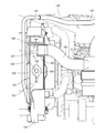
- a first shielding member 146 made of an elastic material such as rubber is attached to the distal end portion of the peripheral wall portion 141 of the shroud 154.
- the first shielding member 146 includes, for example, a groove portion having a groove groove into which the distal end portion of the peripheral wall portion 141 is fitted, and a columnar portion connected to a portion of the groove portion on the opposite side to the concave groove.
- the 1st shielding member 146 is arrange
- the first shielding member 146 is in contact with the inner surface of the right side portion of the front bonnet 11a on the outer peripheral side of the vent hole 200 in a state where the front bonnet 11a is closed and in the closed position, and the gap between the shroud 154 and the front bonnet 11a. Block.
- a second shielding member 147 made of an elastic material such as rubber is disposed on the inner surface side of the right side portion of the front bonnet 11a.
- the second shielding member 147 has the same configuration as the first shielding member 146, for example, and has a groove portion having a concave groove and a columnar portion connected to the groove portion.
- the 2nd shielding member 147 is attached to the front-end
- the second shielding member 147 is arranged so as to be curved so that the central portion is convex toward the engine 5 in a plan view, and the concave shape of the peripheral wall portion 141 of the shroud 154 is in a state where the front bonnet 11a is closed and in the closed position. It abuts on the portion 141a. Further, the second shielding member 147 is arranged so as to continue to the disconnected portion of the first shielding member 146 when the front bonnet 11a is in the closed state.
- the outer periphery of the radiator 153 is surrounded by the peripheral wall portion 141 of the shroud 154. Further, the gap between the shroud 154 and the front bonnet 11 a is closed by the first shielding member 146 and the second shielding member 147. Thus, when the front bonnet 11a is in a closed state, a space between the vent hole 200 and the radiator 153 and a space on the engine 5 side are partitioned. Further, the air flow in the gap between the shroud 154 and the front bonnet 11a is blocked.
- the rice transplanter 1 of this embodiment can suppress the warm air in the hood 11 heated by the heat of the engine 5 from flowing into the air suction side (the vent hole 200 side) of the radiator 153.
- the ventilation hole 200 is disposed on the right side of the front bonnet 11a so as to face the radiator 153, and the first shielding member 146 and the second shielding member 147 surround the outer peripheral side of the ventilation hole 200, the first shielding is performed.
- the air flow between the shroud 154 and the front bonnet 11a is blocked by the member 146 and the second shielding member 147, so that the ratio of the cold air that has passed through the vent hole 200 to the radiator 153 can be improved.
- the second shielding member 147 attached to the front bonnet 11 a is moved upward and removed from the concave portion 141 a of the shroud 154. Is done.
- the second shielding member 147 is formed from the concave portion 141a when the front bonnet 11a is opened.
- the cooling fan 152, the radiator 153, and the shroud 154 are arranged on the right side of the engine 5 (one side in the left-right direction) with the traveling direction of the traveling machine body 2 as the front-rear direction. Therefore, the length of the traveling machine body 2 in the front-rear direction can be shortened compared to the configuration in which the cooling fan, the shroud, and the radiator are disposed in the front-rear direction with respect to the engine.
- the shorter the length of the traveling machine body 2 in the front-rear direction the shorter the seedling planting device 23 (see FIGS. 1 and 2). Since it can be located on the shore side, the remaining planting width on the shore can be reduced.
- an air cleaner 160 is disposed above the engine 5.
- the air cleaner 160 is mounted on an air cleaner bracket 161 that is bolted to the upper portion of the engine 5, for example, the upper surface of the cylinder head cover, and fixing belts 162 that are detachably attached to the air cleaner bracket 161 are attached to the outer periphery of the air cleaner 160. It is wound and fixed in position.
- the air cleaner 160 is connected to one end side of an intake pipe 163 for taking in air and one end side of a supply pipe 164 that supplies air to the engine 5 after purifying the air from the intake pipe 163 in the air cleaner 160.
- the other end of the supply pipe 164 is connected to a fresh air intake port of the engine 5, for example, an intake manifold.
- the other end of the intake pipe 163 is connected to an intake port forming portion 165 formed integrally with the shroud 154.
- the intake port forming portion 165 is formed so as to bulge from the surface on the engine 5 side of the shroud 154 toward the surface on the radiator 153 side above the radiator 153 storage position, and is formed in a concave shape when viewed from the engine 5 side.
- the intake port forming portion 165 has a substantially cylindrical shape, and is formed at a position closer to the rear in the upper region of the radiator 153.
- the intake port forming portion 165 has an intake port 166 on the outer peripheral side surface thereof.
- the intake port 166 is formed by opening approximately half of the contour when viewed from the cylindrical central axis direction of the intake port formation portion 165 toward the lower side, in this embodiment, diagonally forward and lower.
- the substantially circular bulging end surface of the intake port forming portion 165 is closed.
- the intake port forming portion 165 and the intake port 166 are disposed so as to face the vent hole 200, in this embodiment, the upper vent hole 201.
- the intake port forming portion 165 is provided with an outer peripheral side surface portion connecting the proximal end side portion of the intake port forming portion 165 and the bulging end surface so as to divide the intake port 166 into two parts. The strength of has been improved. Further, the outer peripheral side surface of the intake port forming portion 165 is connected to the peripheral wall portion 141 that is protruded and formed on the radiator 153 side at the peripheral portion of the shroud 154, and the strength of the intake port forming portion 165 is improved.
- a plate-shaped shielding member 167 is attached to the bulging end surface of the intake port forming portion 165.
- the shielding member 167 is fixed to two portions of the bulging end surface of the intake port forming portion 165 by two fixing screws 168, and is connected between the intake port 166 and the vent hole 200, in this embodiment, the intake port 166 and the upper surface. Arranged between the pores 201.
- the shielding member 167 is disposed so as to protrude forward and downward with respect to the bulging end surface of the intake port formation portion 165, and covers the intake port 166 when viewed from the right side.
- two rib portions extending from the base end portion to the bulging end surface are formed so as to protrude in the outer peripheral direction corresponding to the mounting position of the fixing screw 168. These rib portions secure the mounting position of the fixing screw 168 and improve the strength of the intake port forming portion 165.
- the core portion 124 of the hydraulic oil cooler 122 is disposed between the vent hole 200 on the right side surface of the bonnet 11a and the radiator 153.
- the core portion 124 is composed of a meandering pipe that meanders in the vertical direction, for example, and is disposed so as to face the center portion from the front portion of the radiator 153.
- two mounting stay members 125, 125 that extend in the front-rear direction and are spaced apart from each other in the vertical direction are fixed to the surface of the core portion 124 on the radiator 153 side.
- the core portion 124 is supported by the radiator 153 by fixing both end portions of the attachment stay members 125, 125 to both end portions of the radiator 153.
- the core portion 124 and the air inlet 166 are arranged at positions shifted in the horizontal direction when viewed from the vent hole 200 side on the right side surface of the bonnet 11.
- the hydraulic oil inlet side of the core portion 124 of the hydraulic oil cooler 122 is connected to the charge drain joint of the hydraulic continuously variable transmission 40 via the hydraulic oil feed pipe 126 and the hydraulic oil feed tube 127. 121 is connected.
- the hydraulic oil outlet side of the core portion 124 is connected to the hydraulic oil return joint 123 of the mission case 6 via the hydraulic oil return pipe 128 and the hydraulic oil return tube 129.
- an intake port 166 of the engine 5 is disposed opposite to the vent hole 200 provided on the right side surface of the bonnet 11, and the intake port 166 and the vent hole 200 are communicated with each other.
- a shielding member 167 that covers the intake port 166 when viewed from the pore 200 side is provided. This prevents water from entering the intake port 166 by the shielding member 167 even when the hood 11 is splashed with water from the right side, for example, during a car wash, and the intake pipe 163, the air cleaner 160, the supply pipe 164 Water can be prevented from entering the intake path of the engine 5 from the intake port 166.
- the air inlet 166 is integrally formed with the shroud 154 surrounding the cooling fan 152 and the shielding member 167 is attached to the shroud 154. Therefore, it is not necessary to provide a member for supporting the shielding member 167 separately from the shroud 154, so that the number of parts and the manufacturing cost can be reduced, and the shielding member 167 can be easily attached.
- the air inlet 166 is opened diagonally forward and downward. Therefore, even in a situation where water is applied from the right side of the bonnet 11 toward the vent hole 200, in addition to the effect of preventing water from entering the intake port 166 by the shielding member 167, the intake port 166 can be more reliably connected. Prevents water from entering.
- the core portion 124 of the hydraulic oil cooler 122 is disposed between the vent hole 200 on the right side surface of the bonnet 11 and the radiator 153, and the intake port 166 is located above the radiator 153. Has been placed. Further, the core portion 124 and the air inlet 166 are disposed at positions displaced in the horizontal direction when viewed from the vent hole 200 side on the right side surface of the bonnet 11. Therefore, the heat generated by staying in the hydraulic oil cooler 122, particularly the core portion 124, can be prevented from being directly sucked into the intake port 166. Thereby, regarding the combustion air taken in from the intake port 166, the temperature rise caused by the heat generation of the hydraulic oil cooler 122 can be suppressed, and consequently the decrease in the output of the engine 5 can be suppressed.
- vent hole 200 on the right side surface of the bonnet 11 is vertically divided into an upper vent hole 201 and a lower vent hole 202, the air inlet 166 faces the upper vent hole 201, and the core portion 124 has the lower vent hole 202. Confronted. Further, the core portion 153 a through which air flows in the radiator 153 has the upper front portion and the upper central portion of the core portion 153 a facing the vent hole 200, and most of the core portion 153 a faces the lower vent hole 202. In addition, the air flowing into the bonnet 11 from the vent hole 200 on the right side surface of the bonnet 11 by the operation of the cooling fan 152 circulates to the engine 5 side through the core portion 153 a of the radiator 153 and the shroud 154.
- air can flow from the upper ventilation hole 201 on the right side surface of the bonnet 11 toward the core portion 153a diagonally to the left, so that the intake port 166 is disposed above the radiator 153, so that the hydraulic oil cooler 122 It is possible to prevent the radiated heat from being directly sucked into the intake port 166.
- the intake port for taking in combustion air of the engine is arranged in the bonnet
- the intake port is often arranged in the vicinity of the vent provided on the side surface of the bonnet.
- the air vent allows water to pass through as well as the air. There was a problem of getting into.
- the air inlet may be integrally formed with a fan shroud surrounding the cooling fan, and the shielding member may be attached to the fan shroud.
- the intake port may be opened downward. As a result, it is possible to more reliably prevent water from entering the intake port from the side.
- a radiator is disposed between the cooling fan and the vent hole, wherein a core portion of the hydraulic oil cooler is disposed between the vent hole and the radiator, and the intake port is disposed on the radiator. It is arrange
- the present invention is not limited to the above-described embodiment, and can be embodied in various forms.
- the configuration of each part is not limited to the illustrated embodiment, and various modifications can be made without departing from the spirit of the present invention.
- the working machine of the present invention can be applied not only to a riding type rice transplanter but also to other working machines such as an agricultural tractor and a wheel loader for civil engineering construction.
Landscapes
- Engineering & Computer Science (AREA)
- Chemical & Material Sciences (AREA)
- Combustion & Propulsion (AREA)
- Mechanical Engineering (AREA)
- Life Sciences & Earth Sciences (AREA)
- Transportation (AREA)
- Soil Sciences (AREA)
- Environmental Sciences (AREA)
- General Engineering & Computer Science (AREA)
- Cooling, Air Intake And Gas Exhaust, And Fuel Tank Arrangements In Propulsion Units (AREA)
- Transplanting Machines (AREA)
- Body Structure For Vehicles (AREA)
Abstract
Description
2 走行機体
5 エンジン
11 ボンネット
11a 前ボンネット
146 第1遮蔽部材
147 第2遮蔽部材
141 周壁部
141a 凹状部
142 給水口部
153 ラジエータ
154 シュラウド
Claims (4)
- エンジンを搭載した走行機体と、エンジンを覆う開閉可能なボンネットと、ボンネット内でエンジンの一側部側に配置されたシュラウド及びラジエータと、シュラウドとボンネットの間の隙間を塞ぐ遮蔽部材を備えた作業機であって、
前記遮蔽部材は、前記ラジエータの外周を囲う前記シュラウドの周壁部に取り付けられるとともに前記ラジエータの給水口部の上方で断絶されている第1遮蔽部材と、前記ボンネットに取り付けられて前記ボンネットが閉じ状態のときに前記第1遮蔽部材の断絶部分に連なる第2遮蔽部材を備えている作業機。 - 前記周壁部は前記ラジエータの前記給水口部の上方が切り欠かれた凹状部を備え、
前記第1遮蔽部材は前記断絶部分が前記凹状部に位置するように前記周壁部に取り付けられ、
前記第2遮蔽部材は前記ボンネットが閉じ状態のときに前記周壁部の前記凹状部に当接する請求項1に記載の作業機。 - 前記走行機体の進行方向を前後方向として前記ボンネットの左右一側部に前記シュラウド及び前記ラジエータに対峙する通気孔を形成し、
前記ボンネットが閉じ状態のときは、前記第1遮蔽部材が前記ボンネットの前記左右一側部の内面に当接して、前記第1及び第2遮蔽部材が前記通気孔の外周側を囲って前記ボンネットの内面と前記シュラウドの間の隙間が塞がれる請求項1に記載の作業機。 - 請求項1に記載の作業機としての田植機。
Priority Applications (3)
| Application Number | Priority Date | Filing Date | Title |
|---|---|---|---|
| KR1020187026683A KR102082279B1 (ko) | 2016-05-02 | 2017-04-12 | 작업기 및 이앙기 |
| CN201780025650.3A CN109070731B (zh) | 2016-05-02 | 2017-04-12 | 作业机及插秧机 |
| KR1020207005165A KR102195667B1 (ko) | 2016-05-02 | 2017-04-12 | 작업기 및 이앙기 |
Applications Claiming Priority (2)
| Application Number | Priority Date | Filing Date | Title |
|---|---|---|---|
| JP2016-092515 | 2016-05-02 | ||
| JP2016092515A JP6612175B2 (ja) | 2016-05-02 | 2016-05-02 | 作業機及び田植機 |
Publications (1)
| Publication Number | Publication Date |
|---|---|
| WO2017191740A1 true WO2017191740A1 (ja) | 2017-11-09 |
Family
ID=60202903
Family Applications (1)
| Application Number | Title | Priority Date | Filing Date |
|---|---|---|---|
| PCT/JP2017/014973 Ceased WO2017191740A1 (ja) | 2016-05-02 | 2017-04-12 | 作業機及び田植機 |
Country Status (5)
| Country | Link |
|---|---|
| JP (1) | JP6612175B2 (ja) |
| KR (2) | KR102195667B1 (ja) |
| CN (1) | CN109070731B (ja) |
| TW (1) | TWI637682B (ja) |
| WO (1) | WO2017191740A1 (ja) |
Cited By (1)
| Publication number | Priority date | Publication date | Assignee | Title |
|---|---|---|---|---|
| ES2976739A1 (es) * | 2022-12-23 | 2024-08-07 | Carretillas Amate Sl | Vehículo agrícola con asiento abatible |
Citations (5)
| Publication number | Priority date | Publication date | Assignee | Title |
|---|---|---|---|---|
| JPH03292273A (ja) * | 1990-04-07 | 1991-12-24 | Yanmar Diesel Engine Co Ltd | トラクタのボンネット機構 |
| JPH1191371A (ja) * | 1997-09-26 | 1999-04-06 | Kubota Corp | 走行車両のボンネット内区画構造 |
| JP2010260444A (ja) * | 2009-05-07 | 2010-11-18 | Yanmar Co Ltd | 農業機械 |
| US20120261202A1 (en) * | 2011-04-13 | 2012-10-18 | Bering Christopher A | Tractor hood airflow system |
| JP2016032966A (ja) * | 2014-07-31 | 2016-03-10 | 株式会社クボタ | 作業車の原動部 |
Family Cites Families (7)
| Publication number | Priority date | Publication date | Assignee | Title |
|---|---|---|---|---|
| EP0079399B1 (de) * | 1981-11-14 | 1986-09-10 | Deere & Company | Reinigungsvorrichtung zum Reinigen des Luftfilters eines Kühlluftgehäuses mit einem ein Gebläse aufweisenden Kühler |
| JPH11350960A (ja) * | 1998-06-05 | 1999-12-21 | Iseki & Co Ltd | エアコン用コンデンサの冷却風装置 |
| JP4847073B2 (ja) * | 2005-08-29 | 2011-12-28 | ヤンマー株式会社 | トラクタ |
| JP2009013794A (ja) * | 2007-06-29 | 2009-01-22 | Iseki & Co Ltd | コンバイン |
| CN102612458B (zh) * | 2009-11-10 | 2015-05-20 | 洋马株式会社 | 乘用型农用作业机 |
| JP6226816B2 (ja) * | 2014-05-26 | 2017-11-08 | 株式会社クボタ | 作業機 |
| CN204055326U (zh) * | 2014-09-03 | 2014-12-31 | 安徽安凯汽车股份有限公司 | 一种客车冷却模块总成 |
-
2016
- 2016-05-02 JP JP2016092515A patent/JP6612175B2/ja active Active
-
2017
- 2017-04-12 KR KR1020207005165A patent/KR102195667B1/ko active Active
- 2017-04-12 CN CN201780025650.3A patent/CN109070731B/zh active Active
- 2017-04-12 WO PCT/JP2017/014973 patent/WO2017191740A1/ja not_active Ceased
- 2017-04-12 KR KR1020187026683A patent/KR102082279B1/ko active Active
- 2017-04-25 TW TW106113745A patent/TWI637682B/zh not_active IP Right Cessation
Patent Citations (5)
| Publication number | Priority date | Publication date | Assignee | Title |
|---|---|---|---|---|
| JPH03292273A (ja) * | 1990-04-07 | 1991-12-24 | Yanmar Diesel Engine Co Ltd | トラクタのボンネット機構 |
| JPH1191371A (ja) * | 1997-09-26 | 1999-04-06 | Kubota Corp | 走行車両のボンネット内区画構造 |
| JP2010260444A (ja) * | 2009-05-07 | 2010-11-18 | Yanmar Co Ltd | 農業機械 |
| US20120261202A1 (en) * | 2011-04-13 | 2012-10-18 | Bering Christopher A | Tractor hood airflow system |
| JP2016032966A (ja) * | 2014-07-31 | 2016-03-10 | 株式会社クボタ | 作業車の原動部 |
Cited By (1)
| Publication number | Priority date | Publication date | Assignee | Title |
|---|---|---|---|---|
| ES2976739A1 (es) * | 2022-12-23 | 2024-08-07 | Carretillas Amate Sl | Vehículo agrícola con asiento abatible |
Also Published As
| Publication number | Publication date |
|---|---|
| CN109070731B (zh) | 2021-11-30 |
| KR102195667B1 (ko) | 2020-12-28 |
| KR20200022523A (ko) | 2020-03-03 |
| JP6612175B2 (ja) | 2019-11-27 |
| TWI637682B (zh) | 2018-10-11 |
| CN109070731A (zh) | 2018-12-21 |
| TW201740795A (zh) | 2017-12-01 |
| JP2017200787A (ja) | 2017-11-09 |
| KR20180112025A (ko) | 2018-10-11 |
| KR102082279B1 (ko) | 2020-02-27 |
Similar Documents
| Publication | Publication Date | Title |
|---|---|---|
| US7559295B2 (en) | Cooling structure for a work vehicle | |
| JP7672523B2 (ja) | 電動作業車 | |
| JP3862674B2 (ja) | 乗用型移植機 | |
| CN111492765A (zh) | 作业机 | |
| KR101050371B1 (ko) | 작업차 | |
| JP6612175B2 (ja) | 作業機及び田植機 | |
| JP2017178246A (ja) | 作業車両 | |
| JP2003072602A (ja) | 移動農機 | |
| JP2020023317A (ja) | 作業機 | |
| JP3599479B2 (ja) | 乗用型移植機 | |
| JP5008109B2 (ja) | 田植機 | |
| JP7423560B2 (ja) | 作業車両の冷却装置および作業車両 | |
| JP2018172083A (ja) | 水田作業機 | |
| JP3934187B2 (ja) | 走行農作業機 | |
| JP2003153616A (ja) | 田植機 | |
| JP4369399B2 (ja) | 走行車両 | |
| JP5524661B2 (ja) | 作業車両 | |
| JP5513363B2 (ja) | 作業機 | |
| JP2003072397A (ja) | 移動農機 | |
| JP4352021B2 (ja) | 走行車両 | |
| JP2003079211A (ja) | 田植機 | |
| KR100963485B1 (ko) | 엔진 냉각장치 및 이를 포함하는 이앙기 | |
| JP5818929B2 (ja) | 乗用型作業機 | |
| JP2011247393A (ja) | 作業機 | |
| JP2010031574A (ja) | 作業機械 |
Legal Events
| Date | Code | Title | Description |
|---|---|---|---|
| ENP | Entry into the national phase |
Ref document number: 20187026683 Country of ref document: KR Kind code of ref document: A |
|
| WWE | Wipo information: entry into national phase |
Ref document number: 1020187026683 Country of ref document: KR |
|
| NENP | Non-entry into the national phase |
Ref country code: DE |
|
| 121 | Ep: the epo has been informed by wipo that ep was designated in this application |
Ref document number: 17792673 Country of ref document: EP Kind code of ref document: A1 |
|
| 122 | Ep: pct application non-entry in european phase |
Ref document number: 17792673 Country of ref document: EP Kind code of ref document: A1 |