WO2017188334A1 - ガラス微粒子の合成方法 - Google Patents
ガラス微粒子の合成方法 Download PDFInfo
- Publication number
- WO2017188334A1 WO2017188334A1 PCT/JP2017/016591 JP2017016591W WO2017188334A1 WO 2017188334 A1 WO2017188334 A1 WO 2017188334A1 JP 2017016591 W JP2017016591 W JP 2017016591W WO 2017188334 A1 WO2017188334 A1 WO 2017188334A1
- Authority
- WO
- WIPO (PCT)
- Prior art keywords
- gas
- glass
- raw material
- flame
- gas port
- Prior art date
- Legal status (The legal status is an assumption and is not a legal conclusion. Google has not performed a legal analysis and makes no representation as to the accuracy of the status listed.)
- Ceased
Links
Images


Classifications
-
- C—CHEMISTRY; METALLURGY
- C03—GLASS; MINERAL OR SLAG WOOL
- C03B—MANUFACTURE, SHAPING, OR SUPPLEMENTARY PROCESSES
- C03B37/00—Manufacture or treatment of flakes, fibres, or filaments from softened glass, minerals, or slags
- C03B37/01—Manufacture of glass fibres or filaments
- C03B37/012—Manufacture of preforms for drawing fibres or filaments
- C03B37/014—Manufacture of preforms for drawing fibres or filaments made entirely or partially by chemical means, e.g. vapour phase deposition of bulk porous glass either by outside vapour deposition [OVD], or by outside vapour phase oxidation [OVPO] or by vapour axial deposition [VAD]
- C03B37/018—Manufacture of preforms for drawing fibres or filaments made entirely or partially by chemical means, e.g. vapour phase deposition of bulk porous glass either by outside vapour deposition [OVD], or by outside vapour phase oxidation [OVPO] or by vapour axial deposition [VAD] by glass deposition on a glass substrate, e.g. by inside-, modified-, plasma- or plasma modified- chemical vapour deposition [ICVD, MCVD, PCVD, PMCVD], i.e. by thin layer coating on the inside or outside of a glass tube or on a glass rod
-
- C—CHEMISTRY; METALLURGY
- C03—GLASS; MINERAL OR SLAG WOOL
- C03B—MANUFACTURE, SHAPING, OR SUPPLEMENTARY PROCESSES
- C03B37/00—Manufacture or treatment of flakes, fibres, or filaments from softened glass, minerals, or slags
- C03B37/01—Manufacture of glass fibres or filaments
- C03B37/012—Manufacture of preforms for drawing fibres or filaments
- C03B37/014—Manufacture of preforms for drawing fibres or filaments made entirely or partially by chemical means, e.g. vapour phase deposition of bulk porous glass either by outside vapour deposition [OVD], or by outside vapour phase oxidation [OVPO] or by vapour axial deposition [VAD]
- C03B37/018—Manufacture of preforms for drawing fibres or filaments made entirely or partially by chemical means, e.g. vapour phase deposition of bulk porous glass either by outside vapour deposition [OVD], or by outside vapour phase oxidation [OVPO] or by vapour axial deposition [VAD] by glass deposition on a glass substrate, e.g. by inside-, modified-, plasma- or plasma modified- chemical vapour deposition [ICVD, MCVD, PCVD, PMCVD], i.e. by thin layer coating on the inside or outside of a glass tube or on a glass rod
- C03B37/01807—Reactant delivery systems, e.g. reactant deposition burners
-
- C—CHEMISTRY; METALLURGY
- C03—GLASS; MINERAL OR SLAG WOOL
- C03B—MANUFACTURE, SHAPING, OR SUPPLEMENTARY PROCESSES
- C03B2207/00—Glass deposition burners
- C03B2207/20—Specific substances in specified ports, e.g. all gas flows specified
-
- C—CHEMISTRY; METALLURGY
- C03—GLASS; MINERAL OR SLAG WOOL
- C03B—MANUFACTURE, SHAPING, OR SUPPLEMENTARY PROCESSES
- C03B2207/00—Glass deposition burners
- C03B2207/50—Multiple burner arrangements
Definitions
- the present invention relates to a method for synthesizing glass fine particles.
- This application claims priority based on Japanese Patent Application No. 2016-087695 filed on Apr. 26, 2016, and incorporates all the content described in the Japanese application.
- Patent Document 1 glass raw material gas and flame forming gas (combustible gas, auxiliary combustion gas, seal gas, etc.) are supplied to a multi-tube burner having a plurality of gas ports, and the glass raw material is formed in the flame formed by the multi-tube burner.
- a method for synthesizing glass fine particles by synthesizing glass fine particles by flame decomposition reaction of gas is disclosed.
- a method for synthesizing glass fine particles according to one embodiment of the present disclosure includes: A glass raw material gas is injected from a central gas port of a multi-tube burner having a plurality of gas ports, and a flame forming gas is injected from a plurality of gas ports outside the central gas port, and formed by the flame forming gas.
- a method of synthesizing glass fine particles by synthesizing glass fine particles by causing a flame decomposition reaction of the glass raw material gas in a flame The multi-tube burner has a protruding portion that protrudes downstream from the central gas port on the gas injection side end face thereof, The flame so that the flow velocity V2 is 0.3 to 1.0 times the gas flow velocity V1 injected from the central gas port from at least one gas port among the gas ports inside the protrusion. Glass particles are synthesized by injecting a forming gas.
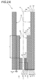
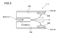
- FIG. 2 is a cross-sectional view showing one embodiment of a multi-tube burner that generates glass particles. It is a schematic diagram explaining the mechanism in which glass microparticles accumulate in a multi-tube burner. It is a schematic diagram explaining the method and conditions which suppress the deposition of the glass particulates in a multi-tube burner.
- the multi-tube burner used in the method for synthesizing glass fine particles as in Patent Document 1 is a protrusion in which the outer gas port is longer than the inner gas port in the radial direction of the multi-tube burner in order to adjust the flame decomposition reaction.
- the part is formed.
- the protruding portion is referred to as a stepped portion, and the stepped portion is provided in two steps. Such a protruding portion can prevent the raw material gas injected from the central gas port from being excessively scattered.
- an object of the present disclosure is to provide a method for synthesizing glass fine particles capable of suppressing loss of opportunity for glass production and substantially eliminating the need for maintenance work of a multi-tube burner.
- a method for synthesizing glass fine particles according to one embodiment of the present invention includes: (1) A glass raw material gas is injected from a central gas port of a multi-tube burner having a plurality of gas ports, and a flame forming gas is injected from a plurality of gas ports outside the central gas port.
- a method for synthesizing glass fine particles by synthesizing glass fine particles by flame decomposition reaction of the glass raw material gas in a flame formed by gas The multi-tube burner has a protruding portion that protrudes downstream from the central gas port on the gas injection side end face thereof, The flame so that the flow velocity V2 is 0.3 to 1.0 times the gas flow velocity V1 injected from the central gas port from at least one gas port among the gas ports inside the protrusion. Glass particles are synthesized by injecting a forming gas. According to this method, the gas flow velocity V1 injected from the central gas port from at least one gas port among the gas ports inside the protruding portion of the multi-tube burner is not less than 0.3 times and not more than 1.0 times.
- the glass raw material gas injected from the central gas port is blocked by the flame forming gas having the flow velocity V2, and almost all glass particles are deposited on the inner wall of the protruding portion. do not do. For this reason, since the clogging of the multi-tube burner does not occur, it is possible to suppress the loss of opportunity for manufacturing the glass and almost eliminate the necessity for the maintenance work of the multi-tube burner.
- the gas flow velocity V1 of the central gas port is 5 m / sec or more and 20 m / sec or less
- the protruding length of the protruding portion is preferably V1 ⁇ 0.01 seconds or less.
- a VAD (Vapor Phase Axial Deposition) method will be described as an example, but the present invention is not limited to the VAD method. Similar to the VAD method, the present invention can be applied to a method of depositing glass from a glass raw material, for example, an OVD (OutsidepositionVapor ⁇ Deposition) method.
- OVD OutsidepositionVapor ⁇ Deposition
- the manufacturing apparatus 1 includes a reaction vessel 2, an elevating and rotating device 3, a gas supply device 4, a multi-tube burner 5, and a control unit 6 that controls the operation of each unit.
- the reaction vessel 2 is a vessel in which the glass particulate deposit M is formed, and includes an exhaust pipe 21 attached to the side surface of the reaction vessel 2.
- the exhaust pipe 21 is a pipe for discharging the glass fine particles 10 not attached as the glass fine particle deposit M to the outside of the reaction vessel 2.
- the elevating / rotating device 3 is a device that can elevate and lower the glass particulate deposit M through the support rod 31 and the starting rod 32.
- the lifting / lowering rotation device 3 controls the operation of the support rod 31 based on a control signal transmitted from the control unit 6.
- the support rod 31 is disposed through a through hole formed in the upper wall of the reaction vessel 2, and a starting rod 32 is attached to one end portion disposed in the reaction vessel 2.
- the support rod 31 is gripped by the lifting and rotating device 3 at the end opposite to the end to which the starting rod 32 is attached.
- the starting rod 32 is a rod on which the glass fine particles 10 are deposited, and is attached to the support rod 31.
- the gas supply device 4 is a device that supplies the glass raw material gas obtained by vaporizing the glass raw material 41 to the multi-tube burner 5.
- the gas supply device 4 includes a raw material container 42 that stores the glass raw material 41, an MFC (Mass Flow Controller) 43 that controls the supply flow rate of the glass raw material gas, and a supply pipe 44 that guides the glass raw material gas to the multi-tube burner 5.
- MFC Mass Flow Controller
- the gas supply device 4 has a temperature control booth 45 that keeps the raw material container 42, the MFC 43, and a part of the supply pipe 44 at a predetermined temperature.
- the MFC 43 controls the supply amount of the glass raw material gas supplied to the multi-tube burner 5 based on the control signal transmitted from the control unit 6 and the flow rate of the glass raw material gas injected from the multi-tube burner 5. is doing.
- the multi-tube burner 5 is for generating glass particles 10 and is made of, for example, a metal material or quartz glass.
- a metal material for example, it is preferable to use stainless steel (SUS: Steel Special Use Stainless) having particularly excellent corrosion resistance.
- the multi-tube burner 5 is supplied with glass source gas and flame forming gas (combustion gas, auxiliary combustion gas, seal gas, etc.).
- glass raw material gas for example, silicon tetrachloride (SiCl 4 ), siloxane or the like is supplied, and as the flame forming gas, for example, a combustion gas such as hydrogen (H 2 ), an auxiliary combustion gas such as oxygen (O 2 ), A seal gas such as nitrogen (N 2 ) is supplied.
- the multi-tube burner 5 generates glass fine particles 10 by causing a flame decomposition reaction of the vaporized glass raw material gas in an oxyhydrogen flame.
- the multi-tube burner 5 sprays and deposits the generated glass fine particles 10 on the starting rod 32 to produce a glass fine particle deposit M having a predetermined outer diameter.
- a gas supply device for supplying the flame forming gas is omitted.
- the control unit 6 controls operations of the elevating and rotating device 3, the gas supply device 4, and the like.
- the control unit 6 transmits a control signal for controlling the ascending / descending speed and the rotating speed of the glass particulate deposit M to the ascending / descending rotation device 3.
- the control unit 6 transmits a control signal for controlling the flow rate of the glass raw material gas sprayed from the multi-tube burner 5 to the MFC 43 of the gas supply device 4.
- FIG. 2A is a longitudinal cross-sectional view of the multi-tube burner 5 cut in the axial direction
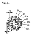
- FIG. 2B is a cross-sectional view of a portion near the central axis B of the multi-tube burner 5 cut in a direction perpendicular to the axial direction. is there.
- the multi-tube burner 5 a multi-tube burner structure such as a 12-fold tube is used.
- the upper direction in FIG. 2A shows the front end direction on the gas injection side of the multi-tube burner 5.
- a raw material gas port 50 through which glass raw material gas is injected is provided at the center of the multi-tube burner 5.
- the raw material gas port 50 can be supplied with only the glass raw material gas, or the glass raw material gas can be mixed with another gas, for example, H 2 gas.
- first flame forming gas ports 61, 65, 69 to which a combustion gas such as H 2 is supplied as a flame forming gas, and for example, O 2 etc. as a flame forming gas are also provided.
- the second flame forming gas ports 63, 67, 71 to which the auxiliary combustion gas is supplied are alternately provided.
- first flame forming gas ports 61, 65, 69 and second flame forming gas ports 63, 67, 71 for example, a seal gas such as N 2 is used as a flame forming gas.
- a seal gas such as N 2 is used as a flame forming gas.
- third flame forming gas ports 62, 64, 66, 68, 70 are provided with third flame forming gas ports 62, 64, 66, 68, 70.
- the raw material gas port 50 is formed by a pipe portion extending along the axial direction of the multi-tube burner 5, and is provided at the center of the multi-tube burner 5.
- the other flame forming gas ports 61 to 71 are formed as gaps between the tube portions arranged concentrically with the raw material gas port 50 (see FIG. 2B).
- the thickness T1 of each of the plurality of tube portions is, for example, about 1 mm.
- the opening thickness T2 of the source gas port 50 and the flame forming gas ports 61 to 71 is, for example, about 2 mm. Note that the thickness T1 of all the pipe portions and the opening thickness T2 of all the gas ports are not necessarily uniform.
- the three pipe portions 50A, 61A, 62A constituting the source gas port 50 and the flame forming gas ports 61, 62 have the same length, and the source gas port 50 ,
- the shortest length among the pipe portions constituting the flame forming gas ports 61 to 71 is formed.
- the four pipe parts from the pipe part 63A constituting the outer peripheral side of the flame forming gas port 63 to the pipe part 66A constituting the flame forming gas port 66 have the same length, and the pipe part 50A. , 61A and 62A.
- five pipe parts from the pipe part 67A constituting the outer peripheral side of the flame forming gas port 67 to the pipe part 71A constituting the flame forming gas port 71 have the same length, and the pipe part 63A It is formed to be longer than ⁇ 66A.
- the length of the tube portion is set for each predetermined region so that the outer gas port is longer than the inner gas port in the radial direction of the multiple tube burner 5 at the distal end portion of the multiple tube burner 5.
- the multi-tube burner 5 has a step portion between the pipe portions 50A, 61A, 62A and the pipe portions 63A to 66A, and between the pipe portions 63A to 66A and the pipe portions 67A to 71A. Are formed.
- the tube portions 50A, 61A, 62A protrude from the end face on the gas injection side to the downstream side (front end direction side) of the multiple tube burner 5.
- This portion is defined as a protruding portion 80, and the length is defined as a protruding length L.
- a second protruding portion 90 is formed that protrudes further to the downstream side of the multiple tube burner 5 than the end surfaces on the gas injection side of the tube portions 63A to 66A.
- the multiple tube burner 5 is provided with such protruding portions 80 and 90, so that the glass raw material gas injected from the raw material gas port 50 can be prevented from excessively diffusing in the radial direction of the multiple tube burner 5. .
- the length of the protruding portion is simply shortened to prevent the accumulation of glass particles on the protruding portion.
- the flame formed by the multi-tube burner changes, and the synthesis speed and amount of the glass fine particles also change, so it is difficult to simply shorten the length of the protrusion.
- the flow rate of the glass raw material gas introduced into the raw material gas port is different for each production facility for the glass fine particle deposit, the region in which the glass fine particles are deposited on the protruding portion varies depending on the flow rate of the glass raw material gas.
- the present inventor has examined the method and conditions for preventing the glass fine particles from depositing on the inner wall of the protruding portion even when the flow rate of the glass source gas is different.
- a method for suppressing deposition of glass particles on the inner wall of the protruding portion 80 of the multiple tube burner 5 will be described with reference to FIG.
- FIG. 4 paying attention to the flame forming gas ports 61, 62, 63 provided between the raw material gas port 50 and the protruding portion 80 of the multi-tube burner 5 shown in FIGS. 2A and 2B, Using the gas injected from these gas ports, a method and conditions for suppressing the diffusion of the glass raw material gas to the protruding portion 80 were examined.
- the flow of the flame forming gas is caused by injecting the flame forming gas at a flow rate within a predetermined range from at least one of the flame forming gas ports 61, 62, 63. It has been found that the flow of the glass raw material gas toward the protruding portion 80 (see the broken line arrow D in FIG. 4) can be suppressed.
- the gas flow velocity V can be calculated by the following equation 1 from the flow rate Q (m 3 / sec) of the gas flowing through the gas port and the cross-sectional area S (m 2 ) of the gas port.
- V Q / S (m / sec) (Formula 1)
- the flow rate of the flame forming gas injected from at least one of the flame forming gas ports 61, 62, 63 (hereinafter referred to as V2) is the glass injected from the source gas port 50. If the flow rate of the raw material gas (hereinafter referred to as V1) is set as a reference, the flow D of the glass raw material gas toward the protruding portion 80 can be suppressed by setting the flow velocity V2 to 0.3 V1 (m / second) or more. all right.
- the upper limit value of the flow velocity V2 for suppressing the decrease in the surface temperature of the glass particulate deposit M so as not to cause a manufacturing problem is 1.0 V1 (m / sec).
- the raw material gas port 50 at the center is provided.
- the glass fine particles are synthesized by injecting the flame forming gas so that the flow velocity V2 is 0.3 to 1.0 times the flow velocity V1 of the glass raw material gas to be injected from.
- the present inventor has found that the region in which the glass fine particles 10 are deposited on the protruding portion 80 changes according to the flow rate of the glass raw material gas, and that the glass fine particles 10 protrude into the protruding portion 80 as the flow velocity V1 of the glass raw material gas increases.
- the flow velocity V1 of glass raw material gas was made slow, the preferable relationship between the flow velocity V1 and the protrusion length L of the protrusion part 80 was examined, for example.
- the present inventor has determined that the protrusion length L of the protrusion 80 is V1 (m / second) when the flow rate V1 of the glass raw material gas is, for example, 5 (m / second) or more and 20 (m / second) or less. It has been found that it is preferable to suppress the deposition of the glass fine particles 10 on the protruding portion 80 by setting it to x 0.01 (second) or less.
- the method for synthesizing the glass fine particles at the time of synthesizing the glass fine particles 10, from at least one gas port of the flame forming gas ports 61, 62, 63, 0.3V1 or more and 1.0V1.
- a flame forming gas having a flow velocity V2 set to (m / sec) is injected below.
- the diffusion of the glass raw material gas having the flow velocity V1 injected from the raw material gas port 50 toward the protruding portion 80 is suppressed by the flow of the flame forming gas or the like having the flow velocity V2.
- the glass particles 10 hardly accumulate on the inner wall of the tube portion 63A constituting the protruding portion 80. Thereby, clogging of the glass particulates 10 in the multi-tube burner 5 can be reduced, the opportunity loss of glass production can be suppressed, and the need for maintenance work for cleaning or replacing the multi-tube burner can be almost eliminated. Can do.
- the upper limit value of the flow velocity V2 is set to 1.0 V1 (m / sec) or less. For this reason, it is possible to prevent the surface temperature of the glass particulate deposit M from being lowered due to the high-speed injection of the flame forming gas and the like, and the glass particulate deposit M to which the glass particulates are well adhered is manufactured. be able to.
- the projecting length L of the projecting portion 80 is V1 (m / sec) ⁇ 0.01 ( Seconds) or less. For this reason, it is possible to further suppress the deposition of the glass fine particles 10 on the inner wall of the pipe portion 63A, to suppress the loss of opportunity for manufacturing the glass, and to substantially eliminate the need for maintenance work of the multi-tube burner.
- the radius of the raw material gas port 50 is r1
- the distance from the central axis B of the multiple tube burner 5 to the tube portion 62A is r2
- the distance from the central axis B of the multiple tube burner 5 to the tube portion 63A is r3 (see FIG. 4).
- the protruding length L of the protruding portion 80 was 0.15 (m).
- V2 0. .2V1. That is, the flow velocity V2 of the flame forming gas injected from the flame forming gas port 63 was 0.2 times the flow velocity V1 of the glass raw material gas injected from the raw material gas port 50.
- Q1, S1, and S2 were set to the same conditions as above.
- Q1, S1, and S2 were set to the same conditions as above.
- the flow velocity of the flame forming gas V2 1.0 V1
- the diffusion of the glass raw material gas toward the protruding portion 80 is further suppressed, and the deposition of the glass fine particles 10 on the inner wall of the tube portion 63A does not occur at all.
- the flow velocity V2 of the flame forming gas is 1.2 V1
- the deposition of the glass fine particles 10 on the inner wall of the pipe portion 63A did not occur at all, but the surface temperature of the glass fine particle deposit M decreased and the glass fine particles The deposit could not be manufactured.
- the amount of the glass fine particles 10 deposited on the inner wall of the pipe portion 63A when the protruding lengths L, V1, and V2 were changed was obtained by simulation.
- the simulation was performed with commercially available thermal fluid analysis software.
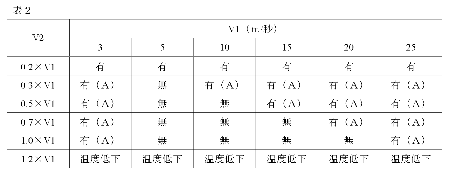
- Table 3 shows a case where the protruding length L is set to 0.013 ⁇ V1, and V1 and V2 are changed.
- the amount of deposition of the glass fine particles 10 is described in three levels: “Yes”, “Yes (A)” (amount that can be easily removed by cleaning), and “No”.
- the glass raw material gas injected from the raw material gas port diffuses more easily as the radius r1 of the raw material gas port 50 is larger, it is particularly preferable to use a multi-tube burner having a larger radius r1 of the raw material gas port 50.
- a multi-stage burner 5 having a two-stage structure having two protruding portions is used, but the present invention is not limited to this. It is sufficient that at least one protruding portion is provided.
- a multi-stage burner having a single-stage structure having only the protruding portion 80 in FIGS. 2A and 2B may be used.
Landscapes
- Chemical & Material Sciences (AREA)
- Engineering & Computer Science (AREA)
- Chemical Kinetics & Catalysis (AREA)
- General Chemical & Material Sciences (AREA)
- Life Sciences & Earth Sciences (AREA)
- General Life Sciences & Earth Sciences (AREA)
- Geochemistry & Mineralogy (AREA)
- Manufacturing & Machinery (AREA)
- Materials Engineering (AREA)
- Organic Chemistry (AREA)
- Glass Melting And Manufacturing (AREA)
- Manufacture, Treatment Of Glass Fibers (AREA)
Abstract
Description
本出願は、2016年4月26日出願の日本出願第2016-087695号に基づく優先権を主張し、前記日本出願に記載された全ての記載内容を援用するものである。
複数のガスポートを有する多重管バーナの中心のガスポートからガラス原料ガスを噴射すると共に前記中心のガスポートの外側の複数のガスポートから火炎形成用ガスを噴射し、前記火炎形成用ガスにより形成される火炎内で前記ガラス原料ガスを火炎分解反応させてガラス微粒子を合成するガラス微粒子の合成方法であって、
前記多重管バーナは、そのガス噴射側端面に前記中心のガスポートより下流側に突き出した突出し部が形成されており、
前記突出し部より内側にあるガスポートのうちの少なくとも1つのガスポートから、前記中心のガスポートから噴射するガス流速V1の0.3倍以上1.0倍以下の流速V2となるように前記火炎形成用ガスを噴射してガラス微粒子の合成を行う。
特許文献1のようなガラス微粒子の合成方法に用いられる多重管バーナは、火炎分解反応の調整などのため、多重管バーナの径方向における内側のガスポートより外側のガスポートの方が長くなる突出し部が形成されている。特許文献1の場合は、突出し部を段差部と称してその段差部が二段設けられている。このような突出し部により、中心のガスポートから噴射される原料ガスが過度に散らばらないようにできる。
本開示によれば、ガラス製造の機会損失を抑制し、多重管バーナの清掃(または交換)作業の必要性をほぼ無くすることができる。
最初に本発明の実施形態を列記して説明する。
本発明の一態様に係るガラス微粒子の合成方法は、
(1)複数のガスポートを有する多重管バーナの中心のガスポートからガラス原料ガスを噴射すると共に前記中心のガスポートの外側の複数のガスポートから火炎形成用ガスを噴射し、前記火炎形成用ガスにより形成される火炎内で前記ガラス原料ガスを火炎分解反応させてガラス微粒子を合成するガラス微粒子の合成方法であって、
前記多重管バーナは、そのガス噴射側端面に前記中心のガスポートより下流側に突き出した突出し部が形成されており、
前記突出し部より内側にあるガスポートのうちの少なくとも1つのガスポートから、前記中心のガスポートから噴射するガス流速V1の0.3倍以上1.0倍以下の流速V2となるように前記火炎形成用ガスを噴射してガラス微粒子の合成を行う。
この方法によれば、多重管バーナの突出し部より内側にあるガスポートのうちの少なくとも1つのガスポートから、中心のガスポートから噴射するガス流速V1の0.3倍以上1.0倍以下の流速V2となるように火炎形成用ガスを噴射するので、中心のガスポートから噴射するガラス原料ガスが、流速V2の火炎形成用ガスに阻まれて、突出し部の内壁にはほとんどガラス微粒子が堆積しない。このため、多重管バーナの目詰まりが生じないので、ガラス製造の機会損失を抑制し、多重管バーナのメンテナンス作業の必要性をほぼ無くすることができる。
前記突き出し部の突出し長さがV1×0.01秒以下であることが好ましい。
上記条件下で、ガラス微粒子の合成を行うことにより、より確実にガラス製造の機会損失を抑制し、多重管バーナの清掃(または交換)作業の必要性をほぼ無くすることができる。
本発明の実施形態に係るガラス微粒子の合成方法の具体例を、以下に図面を参照しつつ説明する。
なお、本発明はこれらの例示に限定されるものではなく、特許請求の範囲によって示され、特許請求の範囲と均等の意味および範囲内でのすべての変更が含まれることが意図される。
図1に示すように、製造装置1は、反応容器2と、昇降回転装置3と、ガス供給装置4と、多重管バーナ5と、各部の動作を制御する制御部6とを備えている。
原料ガスポート50の外周には、火炎形成用ガスとして例えばH2等の燃焼ガスが供給される第一の火炎形成用ガスポート61,65,69と、同じく火炎形成用ガスとして例えばO2等の助燃ガスが供給される第二の火炎形成用ガスポート63,67,71とが交互に設けられている。交互に設けられた第一の火炎形成用ガスポート61,65,69と第二の火炎形成用ガスポート63,67,71との間には、火炎形成用ガスとして例えばN2等のシールガスが供給される第三の火炎形成用ガスポート62,64,66,68,70が設けられている。
この問題が生じる仕組みを図3の模式図を参照して説明する。図3に示すように、原料ガスポートから噴射されたガラス原料ガスの一部は、例えば矢印Cの方向へ勢いよく一気に拡散する。このため、拡散したガラス微粒子が突出し部の内壁に堆積する。
図4に示すように、図2Aおよび図2Bで示した多重管バーナ5の原料ガスポート50と突出し部80との間に設けられている火炎形成用ガスポート61,62,63に着目し、これらのガスポートから噴射されるガスを用いて、突出し部80へのガラス原料ガスの拡散を抑制する方法および条件について検討した。
なお、ガスの流速Vは、ガスポートを流れるガスの流量Q(m3/秒)と、ガスポートの断面積S(m2)とから、次の式1で算出することができる。
V=Q/S(m/秒)・・・(式1)
本実験では、原料ガスポート50と突出し部80との間に設けられている火炎形成用ガスポート61,62,63のうち最も外側に配置されている火炎形成用ガスポート63(燃焼ガスである酸素(O2)が供給される第二の火炎形成用ガスポート)から流速V2のガスを噴射させた。原料ガスポート50には原料ガスとH2ガスを混合したガスを噴射した。
また、原料ガスポート50の流量をQ1、断面積をS1とし、火炎形成用ガスポート63の流量をQ2、断面積をS2とした。また、原料ガスポート50の半径をr1、多重管バーナ5の中心軸Bから管部62Aまでの距離をr2、多重管バーナ5の中心軸Bから管部63Aまでの距離をr3とした(図4参照)。なお、突出し部80の突出し長Lは0.15(m)とした。
S1=π×r12=π×0.0032(m2)
Q2=0.000372(m3/秒)
S2=π×(r32-r22)=π×(0.0112-0.0092)(m2)の条件でガラス微粒子の合成を行い、管部63Aの内壁へのガラス微粒子10の堆積を観察した。
このときの、ガラス原料ガスの流速V1=Q1/S1=15.0(m/秒)、火炎形成用ガスの流速V2=Q2/S2=3.0(m/秒)であり、V2=0.2V1であった。すなわち、火炎形成用ガスポート63から噴射される火炎形成用ガスの流速V2は、原料ガスポート50から噴射されるガラス原料ガスの流速V1の0.2倍であった。
このときの、火炎形成用ガスの流速V2=Q2/S2=4.5(m/秒)であり、V2=0.3V1であった。すなわち、火炎形成用ガスポート63から噴射される火炎形成用ガスの流速V2は、原料ガスポート50から噴射されるガラス原料ガスの流速V1の0.3倍であった。
このときの、火炎形成用ガスの流速V2=Q2/S2=15.0(m/秒)であり、V2=1.0V1であった。すなわち、火炎形成用ガスポート63から噴射される火炎形成用ガスの流速V2は、原料ガスポート50から噴射されるガラス原料ガスの流速V1の1.0倍であった。
このときの、火炎形成用ガスの流速V2=Q2/S2=18.0(m/秒)であり、V2=1.2V1であった。すなわち、火炎形成用ガスポート63から噴射される火炎形成用ガスの流速V2は、原料ガスポート50から噴射されるガラス原料ガスの流速V1の1.2倍であった。
シミュレーションは、市販の熱流体解析ソフトでおこなった。上記実験における突出し長L、V1、V2で計算した管部63Aの内壁付近のガラス微粒子濃度と、上記実験で観察した堆積量を対応させることで、突出し長L、V1、V2を変えた場合をシミュレーションした。
各表の結果では、ガラス微粒子10の堆積量を、「有」、「有(A)」(清掃により容易に除去可能な量)、「無」の3つの水準に分けて表記している。
また、上記実験では火炎形成用ガスの流速V2=1.2V1の場合、管部63Aの内壁へのガラス微粒子10の堆積はまったく生じなかったものの、ガラス微粒子堆積体Mの表面温度が低下して、ガラス微粒子堆積体Mの製造ができなかったことから、表1~表3におけるV2が1.2×V1の場合は、同様にガラス微粒子堆積体Mの表面温度が低下すると考えられる。このため、V2が1.2×V1の場合は、ガラス微粒子10の堆積量にかかわらず、「温度低下」と表記している。


なお、原料ガスポート50の半径r1が大きいほど、原料ガスポートから噴射されたガラス原料ガスが拡散しやすいため、原料ガスポート50の半径r1が大きい多重管バーナを用いる場合が特に好ましい。
2 反応容器
3 昇降回転装置
4 ガス供給装置
5 多重管バーナ
6 制御部
10 ガラス微粒子
31 支持棒
32 出発ロッド
41 ガラス原料
43 MFC
44 供給配管
50 原料ガスポート
61,65,69 (第一の)火炎形成用ガスポート
63,67,71 (第二の)火炎形成用ガスポート
62,64,66,68,70 (第三の)火炎形成用ガスポート
50A,61A~71A 管部
80 突出し部
L 突出し長
M ガラス微粒子堆積体
T1 厚さ
T2 開口厚
Claims (2)
- 複数のガスポートを有する多重管バーナの中心のガスポートからガラス原料ガスを噴射すると共に前記中心のガスポートの外側の複数のガスポートから火炎形成用ガスを噴射し、前記火炎形成用ガスにより形成される火炎内で前記ガラス原料ガスを火炎分解反応させてガラス微粒子を合成するガラス微粒子の合成方法であって、
前記多重管バーナは、そのガス噴射側端面に前記中心のガスポートより下流側に突き出した突出し部が形成されており、
前記突出し部より内側にあるガスポートのうちの少なくとも1つのガスポートから、前記中心のガスポートから噴射するガス流速V1の0.3倍以上1.0倍以下の流速V2となるように前記火炎形成用ガスを噴射してガラス微粒子の合成を行う、ガラス微粒子の合成方法。 - 前記中心のガスポートのガス流速V1は、5m/秒以上20m/秒以下であり、
前記突き出し部の突出し長さがV1×0.01秒以下である、請求項1に記載のガラス微粒子の合成方法。
Priority Applications (3)
| Application Number | Priority Date | Filing Date | Title |
|---|---|---|---|
| KR1020187030838A KR102484035B1 (ko) | 2016-04-26 | 2017-04-26 | 유리 미립자의 합성 방법 |
| JP2018514673A JP6874761B2 (ja) | 2016-04-26 | 2017-04-26 | ガラス微粒子の合成方法 |
| CN201780025712.0A CN109071296B (zh) | 2016-04-26 | 2017-04-26 | 玻璃微粒的合成方法 |
Applications Claiming Priority (2)
| Application Number | Priority Date | Filing Date | Title |
|---|---|---|---|
| JP2016087695 | 2016-04-26 | ||
| JP2016-087695 | 2016-04-26 |
Publications (1)
| Publication Number | Publication Date |
|---|---|
| WO2017188334A1 true WO2017188334A1 (ja) | 2017-11-02 |
Family
ID=60159858
Family Applications (1)
| Application Number | Title | Priority Date | Filing Date |
|---|---|---|---|
| PCT/JP2017/016591 Ceased WO2017188334A1 (ja) | 2016-04-26 | 2017-04-26 | ガラス微粒子の合成方法 |
Country Status (4)
| Country | Link |
|---|---|
| JP (1) | JP6874761B2 (ja) |
| KR (1) | KR102484035B1 (ja) |
| CN (1) | CN109071296B (ja) |
| WO (1) | WO2017188334A1 (ja) |
Cited By (1)
| Publication number | Priority date | Publication date | Assignee | Title |
|---|---|---|---|---|
| CN111377607A (zh) * | 2020-04-24 | 2020-07-07 | 黄宏琪 | 一种用于mcvd的稀土及共掺剂原料蒸汽的输送装置 |
Citations (5)
| Publication number | Priority date | Publication date | Assignee | Title |
|---|---|---|---|---|
| JPS6355135A (ja) * | 1986-08-27 | 1988-03-09 | Sumitomo Electric Ind Ltd | 光フアイバ用母材の製造方法 |
| JPH04228443A (ja) * | 1991-05-13 | 1992-08-18 | Nippon Telegr & Teleph Corp <Ntt> | 光ファイバ母材製造用バーナ |
| JP2005029448A (ja) * | 2003-07-10 | 2005-02-03 | Shin Etsu Chem Co Ltd | 光ファイバ母材の製造方法 |
| JP2012031052A (ja) * | 2010-06-28 | 2012-02-16 | Asahi Glass Co Ltd | ガラス体を製造する方法及びeuvリソグラフィ用の光学部材を製造する方法 |
| JP2013241288A (ja) * | 2012-05-18 | 2013-12-05 | Furukawa Electric Co Ltd:The | ガラス微粒子堆積用バーナおよびガラス微粒子堆積体の製造方法 |
Family Cites Families (5)
| Publication number | Priority date | Publication date | Assignee | Title |
|---|---|---|---|---|
| JPH02275725A (ja) * | 1989-04-17 | 1990-11-09 | Sumitomo Electric Ind Ltd | ガラス微粒子堆積体の製造方法 |
| JP2800554B2 (ja) * | 1991-07-23 | 1998-09-21 | 住友電気工業株式会社 | ガラス母材の製造方法 |
| JP3705169B2 (ja) * | 2000-09-14 | 2005-10-12 | 住友電気工業株式会社 | 多孔質ガラス体の製造方法 |
| JP2003238166A (ja) * | 2002-02-21 | 2003-08-27 | Sumitomo Electric Ind Ltd | ガラス微粒子堆積体の製造方法 |
| JP2015030642A (ja) * | 2013-08-05 | 2015-02-16 | 住友電気工業株式会社 | ガラス微粒子堆積体製造用の多重管バーナおよびガラス微粒子堆積体の製造方法 |
-
2017
- 2017-04-26 KR KR1020187030838A patent/KR102484035B1/ko active Active
- 2017-04-26 JP JP2018514673A patent/JP6874761B2/ja active Active
- 2017-04-26 WO PCT/JP2017/016591 patent/WO2017188334A1/ja not_active Ceased
- 2017-04-26 CN CN201780025712.0A patent/CN109071296B/zh active Active
Patent Citations (5)
| Publication number | Priority date | Publication date | Assignee | Title |
|---|---|---|---|---|
| JPS6355135A (ja) * | 1986-08-27 | 1988-03-09 | Sumitomo Electric Ind Ltd | 光フアイバ用母材の製造方法 |
| JPH04228443A (ja) * | 1991-05-13 | 1992-08-18 | Nippon Telegr & Teleph Corp <Ntt> | 光ファイバ母材製造用バーナ |
| JP2005029448A (ja) * | 2003-07-10 | 2005-02-03 | Shin Etsu Chem Co Ltd | 光ファイバ母材の製造方法 |
| JP2012031052A (ja) * | 2010-06-28 | 2012-02-16 | Asahi Glass Co Ltd | ガラス体を製造する方法及びeuvリソグラフィ用の光学部材を製造する方法 |
| JP2013241288A (ja) * | 2012-05-18 | 2013-12-05 | Furukawa Electric Co Ltd:The | ガラス微粒子堆積用バーナおよびガラス微粒子堆積体の製造方法 |
Cited By (2)
| Publication number | Priority date | Publication date | Assignee | Title |
|---|---|---|---|---|
| CN111377607A (zh) * | 2020-04-24 | 2020-07-07 | 黄宏琪 | 一种用于mcvd的稀土及共掺剂原料蒸汽的输送装置 |
| CN111377607B (zh) * | 2020-04-24 | 2022-02-08 | 黄宏琪 | 一种用于mcvd的稀土及共掺剂原料蒸汽的输送装置 |
Also Published As
| Publication number | Publication date |
|---|---|
| CN109071296A (zh) | 2018-12-21 |
| KR102484035B1 (ko) | 2023-01-02 |
| CN109071296B (zh) | 2021-07-30 |
| KR20180136457A (ko) | 2018-12-24 |
| JP6874761B2 (ja) | 2021-05-19 |
| JPWO2017188334A1 (ja) | 2019-02-28 |
Similar Documents
| Publication | Publication Date | Title |
|---|---|---|
| JP5935882B2 (ja) | ガラス微粒子堆積体の製造方法およびガラス母材の製造方法 | |
| JP5880532B2 (ja) | ガラス微粒子堆積体の製造方法およびガラス母材の製造方法 | |
| JP3705169B2 (ja) | 多孔質ガラス体の製造方法 | |
| EP1572593B1 (en) | Burner for chemical vapour deposition of glass | |
| JPWO2017188334A1 (ja) | ガラス微粒子の合成方法 | |
| JP2015093816A (ja) | ガラス微粒子堆積体の製造方法およびガラス母材の製造方法 | |
| JP5651675B2 (ja) | ガラス多孔質体の製造装置及び製造方法、並びに光ファイバ母材の製造方法 | |
| JP6086168B2 (ja) | ガラス微粒子堆積体の製造方法およびガラス母材の製造方法 | |
| JP2012176861A (ja) | 多孔質ガラス微粒子堆積体の製造方法および製造装置 | |
| JP5762374B2 (ja) | 多孔質ガラス母材の製造装置 | |
| WO2022224725A1 (ja) | バーナ、ガラス微粒子堆積体の製造装置およびガラス微粒子堆積体の製造方法 | |
| JP5598872B2 (ja) | 光ファイバ母材の製造方法 | |
| JP7235056B2 (ja) | ガラス微粒子堆積体製造用バーナ、ガラス微粒子堆積体の製造装置および製造方法 | |
| JP2015030642A (ja) | ガラス微粒子堆積体製造用の多重管バーナおよびガラス微粒子堆積体の製造方法 | |
| JP2012041227A (ja) | 多孔質ガラス母材の製造方法 | |
| JP3143445B2 (ja) | 合成石英の製造方法 | |
| WO2022224804A1 (ja) | 光ファイバ用ガラス母材の製造装置および光ファイバ用ガラス母材の製造方法 | |
| JP5168772B2 (ja) | ガラス微粒子堆積体の製造方法 | |
| JP3785120B2 (ja) | シリカ多孔質母材の製造方法 | |
| WO2019044807A1 (ja) | ガラス微粒子堆積体の製造方法、ガラス母材の製造方法及びガラス微粒子堆積体 | |
| JP4857172B2 (ja) | 光ファイバ用ガラス母材の製造装置及び製造方法 | |
| JP2015059055A (ja) | ガラス微粒子堆積体の製造方法 | |
| JP2005194135A (ja) | 光ファイバ用多孔質母材の製造方法及びガラス母材 | |
| JPH089488B2 (ja) | 光フアイバ用母材の製造方法 |
Legal Events
| Date | Code | Title | Description |
|---|---|---|---|
| ENP | Entry into the national phase |
Ref document number: 2018514673 Country of ref document: JP Kind code of ref document: A |
|
| ENP | Entry into the national phase |
Ref document number: 20187030838 Country of ref document: KR Kind code of ref document: A |
|
| NENP | Non-entry into the national phase |
Ref country code: DE |
|
| 121 | Ep: the epo has been informed by wipo that ep was designated in this application |
Ref document number: 17789616 Country of ref document: EP Kind code of ref document: A1 |
|
| 122 | Ep: pct application non-entry in european phase |
Ref document number: 17789616 Country of ref document: EP Kind code of ref document: A1 |