WO2017188318A1 - 採光装置および採光システム - Google Patents
採光装置および採光システム Download PDFInfo
- Publication number
- WO2017188318A1 WO2017188318A1 PCT/JP2017/016558 JP2017016558W WO2017188318A1 WO 2017188318 A1 WO2017188318 A1 WO 2017188318A1 JP 2017016558 W JP2017016558 W JP 2017016558W WO 2017188318 A1 WO2017188318 A1 WO 2017188318A1
- Authority
- WO
- WIPO (PCT)
- Prior art keywords
- slat
- daylighting
- light
- angle
- incident
- Prior art date
Links
Images


Classifications
-
- E—FIXED CONSTRUCTIONS
- E06—DOORS, WINDOWS, SHUTTERS, OR ROLLER BLINDS IN GENERAL; LADDERS
- E06B—FIXED OR MOVABLE CLOSURES FOR OPENINGS IN BUILDINGS, VEHICLES, FENCES OR LIKE ENCLOSURES IN GENERAL, e.g. DOORS, WINDOWS, BLINDS, GATES
- E06B9/00—Screening or protective devices for wall or similar openings, with or without operating or securing mechanisms; Closures of similar construction
- E06B9/24—Screens or other constructions affording protection against light, especially against sunshine; Similar screens for privacy or appearance; Slat blinds
- E06B9/26—Lamellar or like blinds, e.g. venetian blinds
- E06B9/38—Other details
- E06B9/386—Details of lamellae
-
- E—FIXED CONSTRUCTIONS
- E06—DOORS, WINDOWS, SHUTTERS, OR ROLLER BLINDS IN GENERAL; LADDERS
- E06B—FIXED OR MOVABLE CLOSURES FOR OPENINGS IN BUILDINGS, VEHICLES, FENCES OR LIKE ENCLOSURES IN GENERAL, e.g. DOORS, WINDOWS, BLINDS, GATES
- E06B9/00—Screening or protective devices for wall or similar openings, with or without operating or securing mechanisms; Closures of similar construction
- E06B9/24—Screens or other constructions affording protection against light, especially against sunshine; Similar screens for privacy or appearance; Slat blinds
- E06B9/26—Lamellar or like blinds, e.g. venetian blinds
- E06B9/264—Combinations of lamellar blinds with roller shutters, screen windows, windows, or double panes; Lamellar blinds with special devices
-
- E—FIXED CONSTRUCTIONS
- E06—DOORS, WINDOWS, SHUTTERS, OR ROLLER BLINDS IN GENERAL; LADDERS
- E06B—FIXED OR MOVABLE CLOSURES FOR OPENINGS IN BUILDINGS, VEHICLES, FENCES OR LIKE ENCLOSURES IN GENERAL, e.g. DOORS, WINDOWS, BLINDS, GATES
- E06B9/00—Screening or protective devices for wall or similar openings, with or without operating or securing mechanisms; Closures of similar construction
- E06B9/24—Screens or other constructions affording protection against light, especially against sunshine; Similar screens for privacy or appearance; Slat blinds
- E06B9/26—Lamellar or like blinds, e.g. venetian blinds
- E06B9/28—Lamellar or like blinds, e.g. venetian blinds with horizontal lamellae, e.g. non-liftable
- E06B9/30—Lamellar or like blinds, e.g. venetian blinds with horizontal lamellae, e.g. non-liftable liftable
- E06B9/303—Lamellar or like blinds, e.g. venetian blinds with horizontal lamellae, e.g. non-liftable liftable with ladder-tape
-
- E—FIXED CONSTRUCTIONS
- E06—DOORS, WINDOWS, SHUTTERS, OR ROLLER BLINDS IN GENERAL; LADDERS
- E06B—FIXED OR MOVABLE CLOSURES FOR OPENINGS IN BUILDINGS, VEHICLES, FENCES OR LIKE ENCLOSURES IN GENERAL, e.g. DOORS, WINDOWS, BLINDS, GATES
- E06B9/00—Screening or protective devices for wall or similar openings, with or without operating or securing mechanisms; Closures of similar construction
- E06B9/24—Screens or other constructions affording protection against light, especially against sunshine; Similar screens for privacy or appearance; Slat blinds
- E06B9/26—Lamellar or like blinds, e.g. venetian blinds
- E06B9/28—Lamellar or like blinds, e.g. venetian blinds with horizontal lamellae, e.g. non-liftable
- E06B9/30—Lamellar or like blinds, e.g. venetian blinds with horizontal lamellae, e.g. non-liftable liftable
- E06B9/32—Operating, guiding, or securing devices therefor
- E06B9/322—Details of operating devices, e.g. pulleys, brakes, spring drums, drives
-
- F—MECHANICAL ENGINEERING; LIGHTING; HEATING; WEAPONS; BLASTING
- F21—LIGHTING
- F21S—NON-PORTABLE LIGHTING DEVICES; SYSTEMS THEREOF; VEHICLE LIGHTING DEVICES SPECIALLY ADAPTED FOR VEHICLE EXTERIORS
- F21S11/00—Non-electric lighting devices or systems using daylight
-
- F—MECHANICAL ENGINEERING; LIGHTING; HEATING; WEAPONS; BLASTING
- F21—LIGHTING
- F21S—NON-PORTABLE LIGHTING DEVICES; SYSTEMS THEREOF; VEHICLE LIGHTING DEVICES SPECIALLY ADAPTED FOR VEHICLE EXTERIORS
- F21S11/00—Non-electric lighting devices or systems using daylight
- F21S11/007—Non-electric lighting devices or systems using daylight characterised by the means for transmitting light into the interior of a building
-
- F—MECHANICAL ENGINEERING; LIGHTING; HEATING; WEAPONS; BLASTING
- F21—LIGHTING
- F21V—FUNCTIONAL FEATURES OR DETAILS OF LIGHTING DEVICES OR SYSTEMS THEREOF; STRUCTURAL COMBINATIONS OF LIGHTING DEVICES WITH OTHER ARTICLES, NOT OTHERWISE PROVIDED FOR
- F21V14/00—Controlling the distribution of the light emitted by adjustment of elements
- F21V14/06—Controlling the distribution of the light emitted by adjustment of elements by movement of refractors
-
- F—MECHANICAL ENGINEERING; LIGHTING; HEATING; WEAPONS; BLASTING
- F21—LIGHTING
- F21V—FUNCTIONAL FEATURES OR DETAILS OF LIGHTING DEVICES OR SYSTEMS THEREOF; STRUCTURAL COMBINATIONS OF LIGHTING DEVICES WITH OTHER ARTICLES, NOT OTHERWISE PROVIDED FOR
- F21V23/00—Arrangement of electric circuit elements in or on lighting devices
- F21V23/04—Arrangement of electric circuit elements in or on lighting devices the elements being switches
- F21V23/0442—Arrangement of electric circuit elements in or on lighting devices the elements being switches activated by means of a sensor, e.g. motion or photodetectors
- F21V23/0464—Arrangement of electric circuit elements in or on lighting devices the elements being switches activated by means of a sensor, e.g. motion or photodetectors the sensor sensing the level of ambient illumination, e.g. dawn or dusk sensors
-
- F—MECHANICAL ENGINEERING; LIGHTING; HEATING; WEAPONS; BLASTING
- F21—LIGHTING
- F21V—FUNCTIONAL FEATURES OR DETAILS OF LIGHTING DEVICES OR SYSTEMS THEREOF; STRUCTURAL COMBINATIONS OF LIGHTING DEVICES WITH OTHER ARTICLES, NOT OTHERWISE PROVIDED FOR
- F21V5/00—Refractors for light sources
- F21V5/02—Refractors for light sources of prismatic shape
-
- E—FIXED CONSTRUCTIONS
- E06—DOORS, WINDOWS, SHUTTERS, OR ROLLER BLINDS IN GENERAL; LADDERS
- E06B—FIXED OR MOVABLE CLOSURES FOR OPENINGS IN BUILDINGS, VEHICLES, FENCES OR LIKE ENCLOSURES IN GENERAL, e.g. DOORS, WINDOWS, BLINDS, GATES
- E06B9/00—Screening or protective devices for wall or similar openings, with or without operating or securing mechanisms; Closures of similar construction
- E06B9/24—Screens or other constructions affording protection against light, especially against sunshine; Similar screens for privacy or appearance; Slat blinds
- E06B2009/2417—Light path control; means to control reflection
-
- E—FIXED CONSTRUCTIONS
- E06—DOORS, WINDOWS, SHUTTERS, OR ROLLER BLINDS IN GENERAL; LADDERS
- E06B—FIXED OR MOVABLE CLOSURES FOR OPENINGS IN BUILDINGS, VEHICLES, FENCES OR LIKE ENCLOSURES IN GENERAL, e.g. DOORS, WINDOWS, BLINDS, GATES
- E06B9/00—Screening or protective devices for wall or similar openings, with or without operating or securing mechanisms; Closures of similar construction
- E06B9/24—Screens or other constructions affording protection against light, especially against sunshine; Similar screens for privacy or appearance; Slat blinds
- E06B9/26—Lamellar or like blinds, e.g. venetian blinds
- E06B9/264—Combinations of lamellar blinds with roller shutters, screen windows, windows, or double panes; Lamellar blinds with special devices
- E06B2009/2643—Screens between double windows
Definitions
- One embodiment of the present invention relates to a lighting device and a lighting system.
- This application claims priority based on Japanese Patent Application No. 2016-089662 filed in Japan on April 27, 2016, the contents of which are incorporated herein by reference.
- Patent Document 1 discloses a daylighting apparatus for taking sunlight into a room through a building window or the like.
- the daylighting device described in Patent Literature 1 includes a plurality of daylighting sheets arranged side by side and a rotation mechanism that rotates the daylighting sheet.
- Patent Document 1 describes that according to this daylighting apparatus, it is possible to appropriately adjust the deflection in order to avoid dazzling light entering the room according to the elevation angle of the sun.
- Patent Document 2 discloses an electric blind provided with a slat angle control device that controls the angle of a slat according to time and weather.
- the problems with this structure are that the light incident surface is vertical (parallel to the substrate), the critical angle of total reflection is smaller than that of air because it is filled with a low refractive index material, and the upper part of the slat is seasonal. Therefore, a special blind structure is required because it is necessary to be able to rotate both indoors and outdoors. Thus, it is difficult to realize a daylighting device that satisfies both the suppression of glare and the efficient daylighting of sunlight.
- One aspect of the present invention has been made in order to solve the above-described problems, and an object thereof is to provide a daylighting apparatus and a daylighting system that can achieve both glare suppression and efficient daylighting.
- a daylighting apparatus includes a first slat having light permeability that bends an optical path of light incident from the outside and emits the light toward a predetermined direction in the room.
- a first drive mechanism that drives the first slat; and a control unit that controls the first drive mechanism so as to change an inclination angle of the first slat according to the position of the sun. .
- the first slat may include a plurality of prism structures that change the direction of light in a vertical plane.
- the prism structure mainly functions as a reflection surface of the light, a first surface that forms an angle ⁇ with a reference surface of the first slat, and the incidence of the light. It may function as a surface or an emission surface, and may have at least a second surface that forms an angle ⁇ with the reference surface.
- the daylighting device includes a correlation between a date and time and a tilt angle of the first slat, or a correlation between an incident angle of light on the first slat and a tilt angle of the first slat.
- a storage unit storing a relationship may be provided, and the control unit may control an inclination angle of the first slat based on the correlation stored in the storage unit.
- the daylighting device has an incident height of direct light with respect to a horizontal plane as ⁇ in, an incident direction of the direct light with respect to the horizontal plane as ⁇ in, an inclination angle of the first slat as ⁇ ,
- the controller tilts the upper portion of the first slat toward the indoor side when the offset angle of the light emitted from the first slat from the horizontal plane is ⁇ .
- ⁇ is a negative value
- ⁇ is a positive value
- ⁇ out f ( ⁇ in, ⁇ in, ⁇ )
- the minimum ⁇ that satisfies ⁇ ⁇ may be derived.
- control unit may determine the offset angle ⁇ based on a lower end position of the first slat and a depth of a room in which the lighting device is installed.
- the correlation may be a correlation with respect to the direct light reflected once within the prism structure.
- the daylighting device includes an input unit that inputs the posture of the first slat from the outside, and the control unit is configured to perform the operation based on the signal input from the input unit and the correlation.
- the tilt angle of the first slat may be controlled.
- the prism structure includes the first surface and the second surface arranged on the outdoor side, and 0 ° ⁇ ⁇ 90 ° and 0 ° ⁇ ⁇ ⁇ 90 °. And a combination of the angle ⁇ and the angle ⁇ satisfying ⁇ ⁇ ⁇ may be at least partially included.
- the angle ⁇ and the angle ⁇ may satisfy 64 ° ⁇ ⁇ 90 ° and 42 ° ⁇ ⁇ ⁇ 90 °.
- the prism structure includes the first surface and the second surface arranged on the indoor side, and 0 ° ⁇ ⁇ 90 ° and 0 ° ⁇ ⁇ ⁇ 90 °. And a combination of the angle ⁇ and the angle ⁇ satisfying ⁇ ⁇ ⁇ may be at least partially included.
- the angle ⁇ and the angle ⁇ may satisfy 51 ° ⁇ ⁇ 83 ° and 33 ° ⁇ ⁇ ⁇ 90 °.
- the first slat may be bent along a fold line parallel to the longitudinal direction of the first slat.
- the first region having the polygonal line as a boundary may include the plurality of prism structures, and the second region may have light absorptivity.
- the second surface may have a curved cross-sectional shape perpendicular to the longitudinal direction of the prism structure.
- the daylighting device includes a first slat having a light transmittance that bends an optical path of light incident from the outside and emits the light toward a predetermined direction in the room, and a lower portion of the first slat.
- a second slat that is arranged and shields or diffuses and transmits light incident from the outside, a drive mechanism that drives at least one of the first slat or the second slat, and the position of the sun
- a controller that controls the drive mechanism so as to change the tilt angle of the at least one slat, and the first slat includes a plurality of prism structures that change the direction of light in a vertical plane.
- the prism structure functions mainly as a reflection surface of the light, and functions as a first surface that forms an angle ⁇ with a reference surface of the first slat, and an incident surface or an emission surface of the light. And has a second surface which forms the reference plane and the angle beta, at least.
- the second slat may be capable of changing an inclination angle by being driven in conjunction with or independently of the first slat.
- the daylighting device includes a direct light detection unit that detects direct light around the daylighting device, and the control unit detects the first direct light detected by the direct light detection unit.
- the inclination angle of the slats may be controlled.
- a daylighting system includes the daylighting apparatus according to one aspect of the present invention, and a multi-layer glass in which a pair of glass plates are arranged to face each other with a gap therebetween, and the daylighting apparatus Is provided between the pair of glass plates.
- a daylighting system controls the daylighting device according to one aspect of the present invention, an indoor lighting device, a detection unit that detects indoor brightness, the indoor lighting device, and the detection unit.
- a control unit, and the control unit may control the indoor lighting device based on the illuminance detected by the detection unit.
- FIG. 3B is a cross-sectional view taken along line A-A ′ of FIG. 3A. It is a perspective view of a lighting slat. It is sectional drawing of a lighting part. It is a 1st figure for demonstrating the effect
- each member is appropriately changed to make each member a recognizable size.
- the positional relationship (upper, left, right, front and rear) of the daylighting device is based on the positional relationship (upper, lower, left and right, front and rear) when the daylighting device is used. In this case, the positional relationship of the daylighting device is assumed to coincide with the positional relationship with respect to the paper surface.
- FIG. 1 is a perspective view showing a daylighting apparatus according to the first embodiment.
- the vertical direction vertical direction
- the horizontal direction is the x direction
- the near side the back direction is the z direction.
- FIG. 2 is a side view of the daylighting apparatus according to the first embodiment.
- the daylighting apparatus 1 includes a daylighting unit 3 including a plurality of daylighting slats 2, a support mechanism 4, a drive mechanism 5, and a control unit 6.
- the plurality of daylighting slats 2 are suspended in the vertical direction (y direction) at intervals.
- Each of the daylighting slats 2 is arranged so that the longitudinal direction of the daylighting slats 2 is directed in the horizontal direction (x direction).
- the support mechanism 4 supports the plurality of daylighting slats 2 so as to be movable up and down and rotatable.
- the daylighting slat 2 is configured so that the upper side of the daylighting slat 2 can be rotated in a direction to fall to the indoor side.
- the daylighting slat 2 of the present embodiment corresponds to the first slat in the claims.
- the drive mechanism 5 of the present embodiment corresponds to the first drive mechanism in the claims.
- FIGS. 3A and 3B are diagrams showing a schematic configuration of the daylighting slat 2
- FIG. 3A is a front view
- FIG. 3B is a cross-sectional view taken along the line AA ′ in FIG. 3A.
- the daylighting slat 2 includes a base material 8 having light permeability and a daylighting unit 9.
- the daylighting slat 2 bends the optical path of sunlight incident from the outside and emits it toward a predetermined direction in the room.
- the base material 8 is a long plate-like member extending in one direction (X direction).
- the base material 8 functions as a support member that supports the daylighting unit 9.
- the daylighting unit 9 is provided on the first surface 8 a of the substrate 8.
- the first surface 8a of the substrate 8 is an outdoor surface
- the second surface 8b of the substrate 8 is an indoor surface. Therefore, the daylighting unit 9 is provided outside the base material 8.
- the daylighting unit 9 may be provided on the indoor side of the base material 8.
- the lighting part 9 may be a separate body from the base material 8, or may be formed integrally.
- the length L of the daylighting slat 2 in the longitudinal direction is, for example, about 50 to 3000 mm.
- the length (slat width) W1 in the short direction of the daylighting slat 2 is, for example, about 15 to 35 mm.
- the thickness T of the daylighting slat 2 is, for example, about 0.1 to 3 mm.
- the daylighting unit 9 includes a plurality of prism structures 13 and gaps 14.
- the prism structure 13 is light transmissive.
- the space 14 is a space provided between two adjacent prism structures 13, and air exists in this space. In FIG. 3B and the subsequent drawings, only five prism structures 13 are shown, but more prism structures 13 are actually provided.
- the prism structure 13 is made of an organic material having light transmissivity and photosensitivity such as acrylic resin, epoxy resin, and silicone resin.
- a material in which a polymerization initiator, a coupling agent, a monomer, an organic solvent, or the like is mixed with these organic materials can be used.
- the polymerization initiator contains various additive components such as a stabilizer, an inhibitor, a plasticizer, a fluorescent brightening agent, a release agent, a chain transfer agent, and other photopolymerizable monomers. Also good.
- materials described in Japanese Patent No. 41299991 can be used.
- the total light transmittance of the prism structure 13 is preferably 90% or more in accordance with JIS K7361-1. Thereby, sufficient transparency can be obtained.
- the prism structure 13 extends in the longitudinal direction (x direction) of the daylighting slat 2.
- the plurality of prism structures 13 are provided side by side in the lateral direction (y direction) of the daylighting slat 2.
- the prism structure 13 is a triangular prism-shaped transparent structure. That is, the shape of the cross section perpendicular to the longitudinal direction of the prism structure 13 is a triangle.
- the prism structure 13 changes the direction of incident sunlight in the vertical plane.
- the shape of the prism structure 13 is not limited to a triangular prism shape as described later, and may be a polygonal column shape other than the triangular prism, and is not particularly limited.
- the prism structure 13 includes a first surface 13a that mainly functions as a reflecting surface that reflects incident light, and a second surface 13b that mainly functions as an incident surface on which sunlight enters. And a third surface 13c in contact with the first surface 8a of the substrate 8.
- the first surface 8 a of the base material 8 is referred to as a reference surface J of the daylighting slat 2.
- the angle ⁇ is about 51 ° to 90 °.
- the angle ⁇ is about 33 ° to 90 °.
- the angle ⁇ and the angle ⁇ need not be equal.
- the solar light L that has passed through the window glass is incident on the prism structure 13 and is emitted from the base material 8 in several ways.
- a typical route is shown in FIG. As shown in FIG. 5, when the sunlight L that has passed through the window glass enters the prism structure 13 from the second surface 13b, the sunlight L is reflected by the first surface 13a, and then enters the substrate 8, and Injected from the two surfaces 8b.
- the range of the incident angle of the light L totally reflected by the first surface 13a is the widest, the light incident on the prism structure 13 can be efficiently guided to the second surface 8b side of the substrate 8. it can. As a result, the loss of the light L incident on the prism structure 13 can be suppressed, and the intensity of the light emitted from the second surface 8b of the substrate 8 can be increased.
- the refractive index of the substrate 8 and the refractive index of the prism structure 13 are substantially equal. That is, it is desirable that the base material 8 and the prism structure 13 are integrally formed.
- the refractive index of the base material 8 and the refractive index of the prism structure 13 are greatly different, when light enters the base material 8 from the prism structure 13, the interface between the prism structure 13 and the base material 8 Unnecessary light refraction or reflection may occur. In this case, there is a possibility that problems such as failure to obtain desired lighting characteristics and a decrease in luminance may occur.
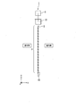
- the support mechanism 4 includes a plurality of ladder cords 16 arranged in parallel in the vertical direction (y direction), a head box 17 that supports upper end portions of the plurality of ladder cords 16, and a plurality of ladder cords 16. And an elevating bar 18 attached to the lower end of the.
- the drive mechanism 5 is accommodated in the head box 17.
- the drive mechanism 5 includes a rotating drum (not shown) that rotates each daylighting slat 9, a lifting drum (not shown) that lifts and lowers the plurality of lighting slats 9, a motor (not shown) that rotates the rotating drum and the lifting drum, and the like. .
- the control unit 6 includes a central processing unit 20 and a memory 21.
- the control unit 6 calculates the tilt angle of the daylighting slats 2 at each time by the central processing unit 20 and changes the tilt angle of the plurality of daylighting slats 2 according to the position of the sun. To control.
- the memory 21 for example, (1) correlation of light incident angle (incident angle of light with respect to the ground plane, incident angle of light with respect to the lighting surface), inclination angle of the lighting slat 2, and light emission angle, (2) Either the correlation between the incident angle of light and the inclination angle of the daylighting slat 2 or (3) the correlation between the date and time and the inclination angle of the daylighting slat 2 is stored in the form of an equation or a table.
- the memory 21 of the present embodiment corresponds to a storage unit in claims.
- the position of the sun can be automatically calculated by, for example, acquiring the latitude and longitude of the installation location by GPS, it is not necessary to prepare a correlation for each installation area.
- the orientation of the installation location can be acquired by a geomagnetic sensor, it is possible to automatically cope with a change in the orientation of the installation surface.
- the offset angle ⁇ is set according to the size of the building (for example, if the depth of the room is wide, the offset angle ⁇ is reduced, and if the depth of the room is narrow, the offset angle ⁇ is increased to illuminate the entire room. ),
- the correlation stored in the memory is different for each offset angle ⁇ .
- the memory 21 may store an information table of the daylighting apparatus 1 including the width and pitch of the daylighting slats 2 in which the daylighting apparatus 1 is installed.
- the daylighting apparatus 1 having the above-described configuration is installed on the indoor side or the outdoor side of the window glass while being suspended from the upper part of a window sash or the like.
- the daylighting slat 2 may be arranged so that the prism structure 13 side faces the indoor side, or the prism structure 13 side faces the outdoor side. May be arranged.
- the daylighting device 1 of the first embodiment at any date and time, sunlight (direct light) incident on the daylighting device 1 is moved upward or downward by an offset angle described later from a horizontal plane parallel to the floor of the room.
- the angle of inclination of the daylighting slat 2 can be controlled so as to be emitted.
- the lighting device 1 may include a remote controller for setting the offset angle.
- the user can adjust the inclination angle of the daylighting slat 2 according to the brightness and dazzling of the room using the remote controller.
- an electric light-shielding blind equipped with a remote controller is conventionally known.
- a light-shielding blind only light reflection occurs, so the relationship between the slat angle and the emission angle is approximately linear.
- the relationship between the slat angle and the emission angle is nonlinear. For example, even when it is desired to change the injection angle once, how many times the slat angle should be changed depends on the date and time.
- the daylighting apparatus 1 of the first embodiment since the correlation between the emission angle, the incident angle of light, and the slat inclination angle is known, it can be controlled to a desired emission angle throughout the year.
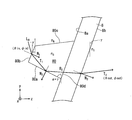
- a virtual plane formed by the extending direction (x direction) of the daylighting slats 2 and the arrangement direction (y direction) of the plurality of daylighting slats 2 is defined as a daylighting surface.
- the lighting surface always coincides with the vertical surface regardless of the inclination angle of the lighting slat 2.
- the angle formed between the normal direction of the reference plane J of the daylighting slat 2 and the sun direction is 0 °
- the incident height of light with respect to the plane K orthogonal to the reference plane J of the daylighting slat 2 is defined as ⁇ s_in
- the emission height of light with respect to the plane K orthogonal to the reference plane J is defined as ⁇ s_out.
- the reference plane J said here is the 1st surface 8a of the base material 8 among the lighting slats 2 as mentioned above.
- the incident height of light with respect to the horizontal plane H is defined as ⁇ h_in
- the emitted height of light with respect to the horizontal plane H is defined as ⁇ h_out.
- the horizontal plane H is a plane that coincides with the plane formed by the horizon in the horizon coordinate system. Therefore, the direction orthogonal to the horizontal plane H corresponds to the zenith direction.
- the direction of the ceiling with respect to the daylighting apparatus 1 is the zenith direction
- the direction of the floor is the nadir direction.
- the light incident height ⁇ s_in and the light exit height ⁇ s_out with respect to the plane K perpendicular to the reference plane J of the daylighting slat 2 change according to the rotation of the daylighting slat 2.
- the light incident height ⁇ h_in and the light exit height ⁇ h_out with respect to the horizontal plane H do not change even when the daylighting slat 2 rotates.
- the incident height ⁇ h_in of light with respect to the horizontal plane H corresponds to the solar altitude.
- the slat In conventional electric blinds, the slat is often made of metal, wood, or the like. Therefore, basically, the angle of the slat is controlled so that direct light is shielded, and the lighting effect is hardly obtained. On the other hand, in the lighting device 1 of the first embodiment, it is possible to efficiently capture direct light while suppressing glare.
- the horizontal plane H described below is a plane that coincides with the plane formed by the horizon in the horizon coordinate system, and is a plane parallel to the floor of the building.
- the daylighting apparatus 1 has a configuration in which the daylighting slat 2 can be tilted by the control of the control unit 6. Therefore, as shown in FIG. 6C, when the incident height ⁇ h_in of the light with respect to the horizontal plane H is 50 °, when the daylighting slat 2 is rotated and the rotation angle ⁇ of the daylighting slat 2 is 10 °, the reference plane J The incident height ⁇ s_in with respect to the plane K orthogonal to is 40 °. At this time, the injection height ⁇ s_out with respect to the plane K perpendicular to the reference plane J is 10 °. Thereby, the injection height ⁇ h_out with respect to the horizontal plane H becomes 0 °.
- the fluctuation of the solar altitude can be offset by the rotation (tilt) of the daylighting slat 2, and the back side of the room can be stably illuminated.
- the rotation angle ⁇ of the daylighting slat is referred to as a slat rotation angle ⁇ .
- the calculation method of the slat rotation angle ⁇ when the relationship of ⁇ s_out ⁇ s_in ⁇ 30 ° holds when the angle formed between the normal direction of the reference plane J of the daylighting slat 2 and the azimuth of the sun is 0 °.
- An example was described.
- this example is for demonstrating the effect of the daylighting apparatus 1 of this embodiment in an easy-to-understand manner, and when the angle formed by the normal direction of the reference plane J and the sun's direction is 0 °. Only holds.
- the daylighting apparatus 1 is installed on a side window where the floor surface of the building and the daylighting surface are in a vertical positional relationship.
- the following design can be calculated by an angle with respect to the floor surface regardless of whether or not the floor surface and the lighting surface are in a vertical positional relationship.
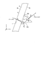
- the coordinate conversion between the orthogonal coordinate system and the horizon coordinate system is as follows. As shown in FIG. 7, the angle formed between the xz plane of the xyz orthogonal coordinate system and the vector L is ⁇ , and the angle formed between the projection of the vector L on the xz plane and the z axis is ⁇ . At this time, the coordinate conversion of the vector L from the orthogonal coordinate system to the horizon coordinate system can be expressed as in equation (5).
- the equation of the light beam in the three-dimensional space can be considered as follows.
- the incident light incident on the interface between the refractive index n A and the refractive index n B is indicated by a vector L
- the reflected light is indicated by a vector R
- the refracted light is indicated by a vector T.
- the normal vector is N.
- the normal vector N is set so that the angle formed with the incident light vector L is 90 ° or less.
- the refractive index of the substance on the emission side of the substrate is n C.
- of each light vector are refractive indexes of the medium. Specifically,
- n A and
- n B.
- is 1.
- Equation (7) is derived from the light refraction formula (Snell's law in a three-dimensional space).
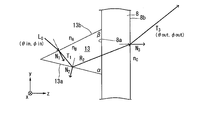
- FIG. 9 shows an optical path of light emitted from the substrate 8 after being reflected once by the first surface 13a of the prism structure 13 in a state where the daylighting slat is not rotated.
- the light that is reflected once by the first surface of the prism structure and emitted is referred to as “one-time reflected light”.
- the incident light vector is L0
- the refracted light vector on the second surface 13b is T1
- the reflected light vector on the first surface 13a is R2
- the emitted light vector from the substrate 8 is T3.
- the normal vector for the second surface 13b is N1
- the normal vector for the first surface 13a is N2
- the normal vector for the second surface 8b of the substrate 8 is N3.
- the angle formed by the first surface 13a of the prism structure 13 and the first surface 8a of the substrate 8 is ⁇
- the angle formed by the second surface 13b of the prism structure 13 and the first surface 8a of the substrate 8 is ⁇ .
- 0 ° ⁇ ⁇ 90 ° and 0 ° ⁇ ⁇ ⁇ 90 ° are satisfied.
- the prism structure is provided on the outdoor side, the light is mainly incident on the second surface 13a, reflected by the first surface 13a, and then emitted through the substrate 8. For this reason, it is preferable that light is more easily incident on the second surface 13b than the first surface 13a. Therefore, ⁇ ⁇ ⁇ is preferable.
- the incident altitude is ⁇ in
- the incident azimuth is ⁇ in
- the exit altitude is ⁇ out
- the exit azimuth is ⁇ out
- ⁇ 90 ° ⁇ ⁇ in ⁇ 90 °, ⁇ 90 ° ⁇ ⁇ in ⁇ 90 °, ⁇ 90 ° ⁇ ⁇ out ⁇ 90 ° and ⁇ 90 ° ⁇ ⁇ out ⁇ 90 ° are satisfied.
- These parameters are shown in a horizon coordinate system with the y-axis as the zenith.
- the altitude is expressed as a positive value in the counterclockwise direction with respect to the horizontal plane and as a negative value in the clockwise direction.
- the refraction light vector T1 the reflection light vector R2, and the emission light vector T3 are obtained, and the following (8), (9), ( 10) is derived.
- Equation (11) is derived from Equations (8), (9), and (10).
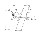
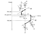
- FIG. 11 shows an optical path of one-time reflected light in a state where the daylighting slat is rotated.
- the slat rotation angle ⁇ as shown in FIG. 12, the case where the daylighting slat 2 is rotated counterclockwise is represented by a positive value, and the case where it is rotated clockwise is represented by a negative value.
- the slat rotation angle ⁇ is negative, and when the upper end of the daylighting slat 2 is rotated outward, the slat rotation angle ⁇ is positive.
- the possible range of the slat rotation angle ⁇ is ⁇ 90 ° ⁇ ⁇ 90 °.
- Equation (18) is solved for ⁇ out, and when ⁇ out is equal to or larger than the offset angle ⁇ , the light is emitted toward the horizontal direction or the ceiling side, so the following equation (19) is derived.
- by 1 ° from ⁇ 0 °. This calculation is basically performed only once when the daylighting apparatus is installed, and thereafter, a correspondence table between the date and time and the slat rotation angle ⁇ may be stored in the memory 21.
- FIG. 13 shows the optical path of one-time reflected light when different daylighting slats are rotated.
- a daylighting slat including a prism structure 80 having a quadrangular cross section perpendicular to the longitudinal direction is shown.
- the prism structure 80 includes a first surface 80a that mainly functions as a reflecting surface that reflects incident light, a second surface 80b that mainly functions as an incident surface on which sunlight is incident, and one side that is a second surface 80b. It has the 3rd surface 80c which touches, and the 4th surface 80d which contact
- Equation (23) is solved for ⁇ out, and when ⁇ out is equal to or larger than the offset angle ⁇ , the light is emitted toward the horizontal direction or the ceiling side, so the following equation (24) is derived.
- by 1 ° from ⁇ 0 °. In this example as well, this calculation may basically be performed once when the daylighting apparatus is installed, and thereafter, a correspondence table between the date and time and the slat rotation angle ⁇ may be stored in the memory 21.
- the refractive index is lower than the refractive index n B of the prism structure 80, for example, as shown in FIG.
- a low refractive index material having nA may be filled.
- the number of base materials 8 is not limited to one, and may be composed of a plurality of sheets.
- FIG. 14 shows an optical path of one-time reflected light when a daylighting slat having a prism structure 83 on the indoor side is rotated.
- FIG. 11 an example of a daylighting slat including a prism structure 83 having a triangular cross section perpendicular to the longitudinal direction is shown.
- the angle formed by the first surface 83a of the prism structure 83 and the first surface 8a of the substrate 8 is ⁇
- the angle formed by the second surface 83b of the prism structure 83 and the first surface 8a of the substrate 8 is ⁇ .
- 0 ° ⁇ ⁇ 90 ° and 0 ° ⁇ ⁇ ⁇ 90 ° are satisfied.
- the prism structure is provided on the indoor side, the light is incident mainly through the base material, reflected by the first surface 83a, and then emitted from the second surface 83b. For this reason, it is preferable that light is more easily incident on the first surface 83a than the second surface 83b. Therefore, ⁇ ⁇ ⁇ is preferable.
- the slat rotation angle ⁇ When the upper end of the daylighting slat is rotated indoors, the slat rotation angle ⁇ is positive, and when the upper end of the daylighting slat is rotated outward, the slat rotation angle ⁇ is negative.
- the normal vectors N1, N2, and N3 are expressed as the following equations (25), (26), and (27), respectively.
- Equation (28) is solved for ⁇ out, and when ⁇ out is equal to or larger than the offset angle ⁇ , the light is emitted toward the horizontal direction or the ceiling side, so the following equation (29) is derived.
- by 1 ° from ⁇ 0 °.
- the daylighting apparatus 1 of the present embodiment even if the position of the sun fluctuates throughout the year or throughout the day, direct light is stably guided to the back of the room while suppressing glare. And efficient lighting can be performed.
- the daylighting apparatus 1 for example, when the solar altitude (incident altitude of light with respect to the horizontal plane) is increased, the daylighting slat 2 is rotated, whereby the normal direction K of the substrate surface is obtained.
- the effect that the incident height can be reduced (first effect) and the effect that the emission height relative to the horizontal plane H can be reduced (second effect) can be combined to bring the light emission direction closer to the horizontal direction, Direct light can be guided to the back of the room.
- the upper side of the daylighting slat 2 is tilted inward (clockwise in FIG. 15A).
- from the emission height relative to the normal direction K of the base material surface are combined. Get closer to the direction.
- the daylighting slats 2 can be rotated only in the direction in which the upper side of the daylighting slats 2 is tilted indoors in the blind using the ladder cord. There are many. Therefore, it is desirable to satisfy the relationship of ⁇ out / ⁇ in> 0 and ⁇ out> 0.
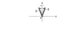
- the flat plate-shaped daylighting slat 2 when used as the daylighting slat, it can often be tilted only in one direction, but the cross-sectional shape perpendicular to the longitudinal direction is Y-shaped, Alternatively, if a T-shaped daylighting slat is used, it can be rotated in either the indoor side or the outdoor side. In this case, the slat rotation angle can be minimized regardless of whether ⁇ out / ⁇ in> 0 and ⁇ out> 0 are satisfied, or ⁇ out / ⁇ in> 0 and ⁇ out ⁇ 0. it can.
- the prism structure has a shape in which 0 ° ⁇ ⁇ 90 ° and 0 ° ⁇ ⁇ ⁇ 90 °, and the slat rotation angle ⁇ 0 in the reference posture of the daylighting slat (in this embodiment, the chamber)
- ⁇ 0 0 °
- ⁇ 0 ⁇ 20 °
- ⁇ out when ⁇ in 0 ° is ⁇ 0 (reference offset angle) It is desirable to have at least part of the combination of the angle ⁇ and the angle ⁇ satisfying 0 ° ⁇ ⁇ 0 ⁇ 5 °.
- the shape of the prism structure does not necessarily have to be a triangular prism, and may be a polygonal prism having three or more triangular prisms.
- the offset angle is 0 °, that is, when light is emitted in the horizontal direction (parallel to the floor surface), the light hits the wall facing the window, so the ceiling is difficult to brighten and the center of the room is hard to brighten. Therefore, according to the size of the room, so that the offset angle is about several degrees, that is, by allowing the light to travel obliquely upward about several degrees toward the ceiling side, from the window side of the room to the back side Can be widely illuminated.
- the distance from the ceiling to the lower end of the lighting device is H ⁇ H 0 [ m].
- the offset angle ⁇ may be determined so that this distance substantially coincides with the depth D of the room. That is, the minimum offset angle ⁇ that satisfies (H ⁇ H 0 ) / tan ⁇ ⁇ D is desirable.
- FIG. 17A it is assumed that the sunlight L incident on the first surface 13a of the prism structure 13 is not refracted but is refracted and emitted from the daylighting slat 2.
- the emission height ⁇ out decreases with an increase in the incident height ⁇ in, so that ⁇ out / ⁇ in ⁇ 0.
- FIG. 17C when the sunlight L incident on the prism structure 13 is reflected an even number of times (in this example, twice) and emitted from the daylighting slat 2, the incident height ⁇ in increases accordingly. Since the injection height ⁇ out decreases, ⁇ out / ⁇ in ⁇ 0.
- the design of the prism structure 13 is as follows: (1) having a fine structure, (2) existence of an odd number of reflection light paths, (3) range of conditions of the incident angle of light to be controlled and the slat rotation angle. It is desirable to satisfy the conditions that the intensity of the odd-numbered reflected light is greater than the intensity of the even-numbered reflected light and that (4), (2) and (3) are in the range of ⁇ out> 0.
- the present inventor performed a simulation of the light emission altitude when the altitude and direction of the sun were variously changed. The results will be described with reference to FIGS.
- a daylighting slat provided with a prismatic prism structure was used, and the refractive index was 1.65.
- the refractive index is preferably in the range of about 1.49 to 1.65.
- the lower taper angle ⁇ of the prism structure was 76 °, and the upper taper angle ⁇ was 64 °.
- the emission angle in the reference posture is 5 °
- the lower taper angle ⁇ of the prism structure was 76 °
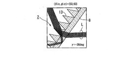
- FIGS. 18 to 23 show simulation results of the daylighting slat having the prism structure on the outdoor side.
- the light Ld is light whose angle has changed by hitting one of the tapered surfaces of the prism structure. Therefore, by bending the light downward from the extension line in the incident direction, the light can be bent directly under the window (for example, within 1.5 m from the window), so that glare is not felt by the office worker in the room.
- FIGS. The simulation results of the daylighting slat having the prism structure on the indoor side are shown in FIGS.
- FIG. 30 the simulation result of the daylighting slat of the comparative example that does not satisfy the angle conditions of 51 ° ⁇ ⁇ ⁇ 83 ° and 33 ° ⁇ ⁇ ⁇ 90 ° is shown in FIG. 30.
- the prism structure can be properly used even if the altitude and direction of the sun change variously. It was found that the light can be emitted substantially in the horizontal direction and the glare can be suppressed by appropriately designing the slat rotation angle ⁇ of the daylighting slat.
- the daylighting slat 2 includes the daylighting unit 9 including the prism structure integrated with the base material 8 has been described.
- the lighting slat is not limited to the above-described configuration, and various configurations can be adopted.
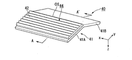
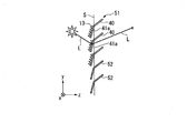
- the daylighting slat 40 of the first modification includes a base material 41 and a daylighting section 44 including a prism structure 42 that is a separate body from the base material 41.
- the base material 41 has a shape bent around a fold line OS parallel to the longitudinal direction.
- the daylighting unit 44 can be controlled in a more vertical posture, and privacy can be protected when the daylighting slat 40 is tilted as the solar altitude increases.
- the daylighting section 44 is provided in the first area 41A, and the daylighting section 44 is not provided in the second area 41B.
- region 41B of the base material 41 has a light absorptivity. Thereby, the glare at the time of rotating the lighting slat 40 can be reduced.
- the base material itself of the portion of the second region 41B may have light absorption, for example, a colored layer provided on the surface of the second region 41B, etc. Light absorptivity may be imparted.
- the angle ⁇ formed by the first region 41A and the second region 41B constituting the substrate 41 is appropriately set according to the shape of the prism structure 42 formed in the first region 41A.
- the base material 41 may be curved in a cross section perpendicular to the longitudinal direction of the base material 41 and may have a curved surface. Thereby, coloring of the lighting part by spectroscopy can be reduced. In addition, by making the incident surface or the exit surface curved instead of the reflecting surface, variation in the light exit angle can be reduced.
- the substrate 41 is made of a light transmissive resin such as a thermoplastic polymer, a thermosetting resin, or a photopolymerizable resin.
- a light transmissive resin such as a thermoplastic polymer, a thermosetting resin, or a photopolymerizable resin.
- the light transmissive resin for example, a resin made of an acrylic polymer, an olefin polymer, a vinyl polymer, a cellulose polymer, an amide polymer, a fluorine polymer, a urethane polymer, a silicone polymer, an imide polymer, or the like is used. Can do.
- polymethyl methacrylate resin PMMA
- triacetyl cellulose PET
- cycloolefin polymer COP
- PC polycarbonate
- PEN polyethylene naphthalate
- PES polyethersulfone
- PI polyimide
- the total light transmittance of the substrate 41 is preferably 90% or more according to JIS K7361-1. Thereby, sufficient transparency can be obtained.
- the configuration and shape of the prism structure 42 are as described in the first embodiment.
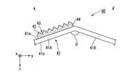
- the daylighting slat 40 of the first modification efficient daylighting can be performed while suppressing glare. Furthermore, when the solar altitude is low, as shown in FIG. 33, light LB that is transmitted through the prism structure 42 of the daylighting slat 40 and is emitted obliquely downward is likely to be generated. However, with the configuration of the first modification, the light LB that is transmitted through the first region 41A of the base material 41 and is emitted obliquely downward can be absorbed by the second region 41B. Thereby, glare can be suppressed.
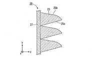
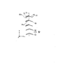
- the daylighting slat 26 according to the second modification includes a base material 27 and a plurality of prism structures 25 provided on the base material 27.
- the first surface 25a that mainly functions as a reflecting surface is a flat surface
- the second surface 25b that mainly functions as an incident surface is a curved surface.
- the daylighting slat 26 of the second modified example it is possible to perform efficient daylighting while suppressing glare by appropriately adjusting the slat rotation angle ⁇ of the daylighting slat. Furthermore, since the second surface 25b that functions as the light incident surface is a curved surface, color breakup due to wavelength dispersion can be suppressed.
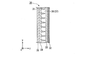
- the daylighting slat 36 of the third modified example includes a daylighting sheet 37 including a prism structure 30, a low refractive index material layer 31, a hard coat layer 32, a base material layer 33, and an adhesive layer. 34 and a panel 35.
- the daylighting slat 26 of the third modified example it is possible to perform efficient daylighting while suppressing glare by appropriately adjusting the slat rotation angle ⁇ of the daylighting slat.
- the daylighting slat 85 of the fourth modified example includes a base material 8, a daylighting sheet 9 including a plurality of prism structures 13, and an anisotropic light diffusion sheet 11.
- the daylighting slat 85 is different from the above embodiment in that the anisotropic light diffusing sheet 11 is provided.
- the anisotropic light diffusion sheet 11 is bonded to the base material 8 by an adhesive layer (not shown).
- the anisotropic light diffusion sheet 11 strongly diffuses the light L sequentially emitted from the daylighting sheet 9 and the base material 8 in the horizontal direction. Specifically, the light L emitted from the substrate 8 is more extended in the direction of the plurality of prism structures 13 (X direction) than in the direction perpendicular to the direction of extension of the plurality of prism structures 13 (Y direction). ) Strongly diffuse in the direction parallel to.
- the anisotropic light diffusion sheet 11 may be composed of, for example, a lenticular lens including a plurality of cylindrical lenses.
- each cylindrical lens extends in the short side direction of the daylighting slat 85, and is arranged in parallel to each other in a direction perpendicular to the extending direction of each cylindrical lens. That is, the arrangement direction (extending direction) of the plurality of cylindrical lenses is orthogonal to the arrangement direction (extending direction) of the plurality of prism structures 13 of the daylighting sheet 9 described above.
- the lens surface of the cylindrical lens has a curvature in a horizontal plane and does not have a curvature in the vertical direction. For this reason, the cylindrical lens has strong light diffusibility in the horizontal direction and does not have light diffusibility in the vertical direction. Therefore, the light L is diffused and emitted in the horizontal direction in the anisotropic light diffusion sheet 11 while maintaining the vertical angle distribution when emitted from the daylighting sheet 9 (prism structure 13).
- the anisotropic light diffusion sheet 11 is configured separately from the daylighting sheet 9 and the base material 8.
- the anisotropic light diffusion sheet 11 may be configured integrally with the daylighting sheet 9 and the base material 8.
- the second surface side of the substrate 8 may be processed to form a plurality of cylindrical lenses integrally with the substrate 8.
- the anisotropic light diffusing sheet 11 does not necessarily need to be composed of a lenticular lens, and may be composed of, for example, a translucent sheet provided with a plurality of convex portions extending in approximately one direction.
- a daylighting slat 86 having a configuration in which the daylighting sheet 9 and the anisotropic light diffusion sheet 11 are directly bonded to each other without using the substrate 8 may be employed.
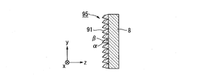
- a daylighting slat 95 of the fifth modification includes a base material 8 and a plurality of prism structures 91 having a quadrangular cross section provided on the outdoor side of the base material 8.
- the daylighting slat 96 of the sixth modification includes a base material 8 and a plurality of prism structures 92 having a quadrangular cross section provided on the outdoor side of the base material 8.
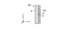
- the daylighting slat 97 of the seventh modified example includes a base material 8 and a plurality of prism structures 93 having a square cross section provided on the indoor side of the base material 8.
- FIG. 41 is a perspective view of the daylighting device of the second embodiment, and corresponds to FIG. 1 of the first embodiment.
- FIG. 41 and FIGS. 42A to 42C the same reference numerals are given to the same components as those used in the first embodiment, and the description thereof will be omitted.
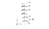
- the daylighting device 51 of the second embodiment includes a plurality of daylighting slats 2, a plurality of light shielding slats 52, a support mechanism 4, a drive mechanism 5, and a control unit 6. .
- a plurality of light shielding slats 52 constitute a light shielding unit 53. That is, in the first embodiment, all the slats are the daylighting slats 2, whereas in the second embodiment, the plurality of slats include the daylighting slats 2 and the light shielding slats 52.
- the plurality of daylighting slats 2 are installed above the eyes of the office workers so that the indoor office workers are not dazzled because the sunlight is bent toward the ceiling of the room.
- the plurality of light shielding slats 52 are installed below the plurality of daylighting slats 2.
- the daylighting slat 2 is the same as the daylighting slat 2 of the first embodiment.
- the light shielding slat 52 is made of, for example, a metal such as aluminum or wood, and shields light.
- the shape of the light shielding slat 52 is not particularly limited as long as it can shield light.
- a diffuse transmission slat may be used instead of the light shielding slat 52.
- the diffuse transmission slat is a transparent resin plate material such as polycarbonate having light scattering properties, and diffuses and transmits light.
- the light shielding slat 52 and the diffuse transmission slat of the second embodiment correspond to the second slat in the claims.
- the plurality of light shielding slats 52 are configured such that the inclination angle of each light shielding slat 52 can be changed. In the case of the second embodiment, the plurality of light shielding slats 52 are rotated in conjunction with the plurality of daylighting slats 2 by the drive mechanism 5.
- daylighting slats 40 having a shape in which a flat plate is bent may be used.
- the plurality of daylighting slats 40 are arranged such that the first portion 41a provided with the plurality of daylighting units is parallel to the daylighting surface S.
- the sunlight L is bent by the plurality of prism structures 13 and emitted toward the back of the room.
- the plurality of light shielding slats 52 at least a part of the light shielding slats 52 is arranged in parallel to the lighting surface S.
- the plurality of daylighting slats 40 do not rotate when the solar altitude increases, it is difficult for the sunlight L to illuminate only the vicinity of the window and illuminate the back side of the room.
- the plurality of daylighting slats 40 rotate in a direction in which the upper end side is inclined indoors with respect to the daylighting surface S.
- the sunlight L can illuminate the back side of the room.
- the plurality of light shielding slats 52 rotate in a direction in which the upper end side is inclined inward with respect to the lighting surface S in conjunction with the plurality of daylighting slats 40.
- the plurality of daylighting slats 40 include first portions 41a provided with a plurality of prism structures 13. It rotates to a position close to perpendicular to the lighting surface S.
- the plurality of light shielding slats 52 are also rotated to a position close to the perpendicular to the lighting surface S. Thereby, the viewability of the daylighting device 51 is improved, and the office worker can visually recognize the outdoor scenery.
- the daylighting device 51 since the daylighting device 51 includes the light shielding slats 52, glare can be more sufficiently suppressed. Further, since the plurality of light shielding slats 52 are rotated in conjunction with the plurality of daylighting slats 2 and 40, it is not necessary to separately provide a drive mechanism for the light shielding slats 52, and the configuration of the daylighting device 51 can be prevented from becoming complicated. .
- the plurality of light shielding slats 52 may be configured to rotate independently of the plurality of daylighting slats 2. In this case, the plurality of light shielding slats 52 may be configured to rotate automatically or may be configured to rotate manually. When the plurality of light shielding slats 52 are configured to rotate independently, the number of drive mechanisms is increased, but the light shielding slats 52 can be tilted more indoors to the direct shielding angle. Thereby, the amount of light collection can be increased. In the present embodiment, the plurality of light shielding slats 52 change the tilt angle, but may not change the tilt angle.
- FIG. 43 is a perspective view of the daylighting device of the third embodiment, corresponding to FIG. 1 of the first embodiment.
- FIG. 43 and FIGS. 44A to 44D the same components as those used in the first embodiment are denoted by the same reference numerals, and description thereof is omitted.
- the daylighting device 61 of the third embodiment includes a plurality of daylighting slats 2, a plurality of light shielding slats 52, a support mechanism 4, a first drive mechanism 63, and a second drive mechanism 64. And a direct light detection unit 65 and a control unit 66.
- the first drive mechanism 63 and the second drive mechanism 64 are accommodated in the head box 17.
- the plurality of daylighting slats 2 are configured to be rotatable by the first drive mechanism 63, and the inclination angle of each daylighting slat 2 is configured to be changeable.
- the plurality of light shielding slats 52 are configured to be rotatable by the second drive mechanism 64, and the inclination angle of each light shielding slat 52 is configured to be changeable. That is, the daylighting device 61 of the third embodiment includes a second drive mechanism 64 that drives the light shielding slats 52 independently of the driving of the daylighting slats 2.
- the configurations of the daylighting slats 2 and the light shielding slats 52 are the same as those in the first embodiment and the second embodiment.
- the direct light detector 65 detects the presence or absence of direct light in the building where the daylighting device 61 is installed or in the peripheral part of the building.
- the direct light detection unit 65 may detect any amount of solar radiation, luminance, illuminance, etc., as long as the daylighting device 61 can detect the presence or absence of direct light received directly from the sun. Can be used.
- the installation position of the direct light detection unit 65 may be any one of, for example, a rooftop of a building, an outer wall, a window, and a room. For example, when a plurality of daylighting devices 61 are installed in one building, the plurality of daylighting devices 61 may also serve as one direct light detection unit 65.
- the direct light detection unit 65 for example, (1) a sun tracking type illuminance sensor or solar radiation amount sensor, (2) a fisheye camera, or the like can be used.
- (1) includes a first illuminance meter that tracks the sun and a second illuminance meter that measures the illuminance by the sky light excluding the periphery of the sun, and whether it is clear or cloudy depending on the difference between the measured values of each illuminometer And control the slats.
- a sky image of the whole sky is picked up by a fish-eye camera, and solar radiation is applied to a plurality of areas obtained by dividing the whole sky based on at least one index of luminance value, R value, B value, and G value. Judge the condition of the weather.
- daylighting slats 40 having a shape obtained by bending a flat plate may be used.
- the control unit 66 controls the inclination angle of the daylighting slat 2 based on the direct solar radiation amount detected by the direct solar radiation amount detection unit 65. For example, when the control unit 66 determines that the amount of direct solar radiation is greater than a predetermined threshold value on a clear day, as shown in FIGS. 44A and 44B, a plurality of daylighting slats 40 according to the solar altitude, as in the second embodiment. Is controlled to an inclination angle so that light can be guided to the back of the room, while the plurality of light shielding slats 52 are controlled to be a solar radiation shielding angle or to be fully closed.
- control unit 66 determines that the amount of direct solar radiation is below a predetermined threshold during cloudy or rainy weather, for example, as shown in FIG. 44C, the lighting slats 40 and the light shielding slats 52 are both leveled. The amount of light extraction can be increased while ensuring the view.
- the control unit 66 may control the inclination angle of the daylighting slat 40 to be a predetermined value when it is determined that the amount of direct solar radiation is not more than a predetermined threshold.
- the lighting device 61 not only direct sunlight but also reflected light from surrounding buildings may reach the lighting device 61.
- the memory 21 of the control unit 66 stores the position and height of the surrounding building, the installation position information of the plurality of daylighting devices 61 in the building, etc., it is determined whether or not there is reflected light. Judgment can be made. This reflected light amount may be added to the determination of opening / closing of the slats.
- the same effects as those in the first and second embodiments can be obtained, such as providing a daylighting device that can achieve both glare suppression and efficient daylighting.
- control unit 66 controls the inclination angles of the daylighting slats 2 and 40 and the shading slats 52 based on the amount of direct solar radiation, efficient lighting and glare according to the amount of direct solar radiation are achieved. In addition to being able to be suppressed, it is possible to ensure the viewability especially in cloudy weather and rainy weather. Further, since the daylighting slats 2 and 40 and the light shielding slats 52 rotate independently, it is possible to control the daylighting slats 2 and 40 and the light shielding slats 52 to have optimum tilt angles.
- FIGS. 45A to 45C The basic configuration of the daylighting device of this embodiment is the same as that of the second embodiment, and the operations of a plurality of daylighting slats are different from those of the second embodiment.
- FIG. 45A is a first diagram for describing an example of an operation method of the daylighting device according to the fourth embodiment.
- FIG. 45B is a second diagram for explaining an example of the operation method of the daylighting device according to the fourth embodiment.
- FIG. 45C is a third diagram for describing an example of the operation method of the daylighting device of the fourth embodiment.
- 45A to 45C the same reference numerals are given to the same components as those used in the second embodiment, and the description thereof will be omitted.
- the daylighting apparatus 101 of the fourth embodiment includes a plurality of daylighting slats 40, a plurality of light shielding slats 52, a support mechanism 4, a drive mechanism 5, and a control unit 6. . That is, in the fourth embodiment, as in the second embodiment, the plurality of slats include the daylighting slats 40 and the light shielding slats 52.
- the plurality of daylighting slats 40 are installed above the eyes of the office worker in the room.
- the plurality of light shielding slats 52 are installed below the plurality of daylighting slats 40.
- the configuration of the daylighting slat 40 itself is the same as that of the daylighting slat 2 of the first embodiment.
- the daylighting slat 40 may be manually rotatable or may be automatically rotated by the drive mechanism 5.
- the configuration of the light shielding slat 52 itself is the same as that of the light shielding slat 52 of the second embodiment. In the present embodiment, the light shielding slat 52 is configured to be automatically rotated by the drive mechanism 5.
- the drive mechanism 5 drives at least one of the daylighting slats 40 or the light shielding slats 52. Moreover, the control part 6 controls the drive mechanism 5 so that the inclination-angle of at least one slat may be changed according to the position of the sun.
- the plurality of daylighting slats 40 are arranged such that the first portions 41a provided with a plurality of daylighting units are parallel to the daylighting surface S. It is fixed in the state. That is, at the time of fine weather, the control unit 6 does not perform control to change the inclination angle of the daylighting slat 40. As a result, the sunlight L is bent by the plurality of prism structures 13 and emitted toward the back of the room.
- the plurality of light shielding slats 52 are controlled by the control unit 6 so that the inclination angle becomes the solar radiation shielding angle according to the position of the sun.
- the plurality of daylighting slats 40 may be arranged such that the first portion 41 a provided with the plurality of daylighting units is parallel to the daylighting surface S.
- the plurality of daylighting slats 40 may be arranged such that the first portion 41 a provided with the plurality of daylighting units is positioned near to the daylighting surface S.
- the plurality of daylighting slats 40 may be arranged so as to be at an intermediate position between FIGS. 45B and 45C. Further, the position of the daylighting slat 40 may be manually adjusted during cloudy weather or may be controlled electrically.
- the plurality of light shielding slats 52 are controlled by the control unit 6 so as to be in a position close to perpendicular to the lighting surface S, for example.
- the same effect as that of the first embodiment can be obtained, in which a daylighting device capable of achieving both glare suppression and efficient daylighting can be provided.
- the daylighting slat 40 has a prism structure that has a large contribution of even-numbered reflected light (refracted light, twice-reflected light). May become glare.
- the daylighting slat 40 needs to be installed above the office worker's line of sight, but in a building with a low ceiling, the daylighting slat 40 may not be sufficiently arranged above the office worker's line of sight.
- the amount of light can be increased by electrically controlling the light shielding slat 52 instead of the daylighting slat 40. .
- movement for raising light collection amount according to the weather or the outdoor brightness becomes high.
- FIG. 46 is a perspective view of the daylighting system of the fifth embodiment.
- FIG. 47 is a sectional view of the daylighting system. 46 and 47, the same reference numerals are given to the same components as those used in the first embodiment, and the description thereof will be omitted.
- the daylighting system 71 includes a daylighting device 51 and a multilayer glass 74.
- the multi-layer glass 74 has a configuration in which a pair of glass plates are arranged to face each other with a gap therebetween.
- the daylighting device 51 is provided between the outdoor side glass plate 72 and the indoor side glass plate 73 constituting the plurality of glasses 74.
- 46 and 47 show an example of the daylighting device 51 of the second embodiment having the daylighting slats 2 and the light shielding slats 52, any one of the daylighting devices of the first to third embodiments may be used.
- the daylighting system 71 of the present embodiment includes the daylighting devices of the first to fourth embodiments, glare suppression and efficient daylighting can be realized.
- the daylighting device 51 is installed inside the multilayer glass 74 and is protected from moisture, impact, and the like, which are external factors that cause deformation and alteration of the slats, the daylighting slats 2 and the light shielding slats 52 are hardly deteriorated. The lighting effect and the light shielding effect can be sufficiently maintained. Further, since the window and the daylighting device 51 are integrated as the daylighting system 71, the difference in appearance due to the presence or absence of the daylighting device 51 is reduced, and the uniformity of the external appearance of the building is improved.
- FIG. 48 is a diagram showing a room model 2000 including a daylighting device and an illumination dimming system, and is a cross-sectional view taken along the line AA ′ of FIG.
- FIG. 49 is a plan view showing the ceiling of the room model 2000.
- the ceiling material constituting the ceiling 2003a of the room 2003 into which sunlight is introduced may have high light reflectivity.
- a light-reflective ceiling material 2003A is installed on the ceiling 2003a of the room 2003 as a light-reflective ceiling material.
- the light-reflective ceiling material 2003A promotes introduction of external light from the daylighting apparatus 2010 installed in the window 2002 toward the back of the room.
- the light-reflective ceiling material 2003A is installed on the ceiling 2003a near the window. Specifically, it is installed in a predetermined area E (an area about 3 m from the window 2002) of the ceiling 2003a.
- the light-reflective ceiling material 2003A is efficient for the sunlight introduced into the room through the window 2002 in which the daylighting device 2010 of any of the above-described embodiments is installed. Lead well. Sunlight introduced from the daylighting apparatus 2010 toward the indoor ceiling 2003a is reflected by the light-reflective ceiling material 2003A and changes its direction to illuminate the desk surface 2005a of the desk 2005 placed in the interior of the room. The effect of brightening the desk top surface 2005a is exhibited.
- the light-reflective ceiling material 2003A may be diffusely reflective or specularly reflective, but has the effect of brightening the desk top surface 2005a of the desk 2005 placed in the interior of the room, and is in the room. In order to achieve both the effects of suppressing glare light that is unpleasant for humans, it is preferable that the characteristics of both are appropriately combined.
- the vicinity of the window 2002 often has a sufficient amount of light. Therefore, by using the light-reflective ceiling material 2003A as described above, the light incident on the ceiling (region E) near the window can be distributed toward the back of the room where the amount of light is small compared to the window.
- the light-reflective ceiling material 2003A is formed by embossing a metal plate such as aluminum with unevenness of about several tens of micrometers, or by depositing a metal thin film such as aluminum on the surface of a resin substrate on which similar unevenness is formed. Can be created. Or the unevenness
- the light distribution characteristics of light and the distribution of light in the room can be controlled.
- the light reflected by the light-reflective ceiling material 2003A is in the left-right direction of the window 2002 (direction intersecting the longitudinal direction of the unevenness). spread.
- the light reflecting ceiling material 2003A diffuses light in the horizontal direction and reflects it toward the back of the room. be able to.
- the daylighting device 2010 is used as part of the illumination dimming system in the room 2003.
- the lighting dimming system includes, for example, a lighting device 2010, a plurality of indoor lighting devices 2007, a solar radiation adjusting device 2008 installed in a window, a control system thereof, and a light-reflective ceiling material 2003A installed on a ceiling 2003a. And the constituent members of the entire room including
- the window 2002 of the room 2003 is provided with a daylighting device 2010, a daylighting slat is arranged on the upper side, and a light shielding slat 2008 is arranged on the lower side.
- the daylighting apparatus of the second embodiment is used as the daylighting apparatus 2010, but is not limited thereto.
- a plurality of indoor lighting devices 2007 are arranged in a grid in the left-right direction (Y direction) of the window 2002 and the depth direction (X direction) of the room.
- the plurality of indoor lighting devices 2007 together with the daylighting device 2010 constitute an entire lighting system of the room 2003.
- the indoor lighting devices 2007 are arranged in a grid pattern with an interval P of 1.8 m in the horizontal direction (Y direction) and the depth direction (X direction) of the ceiling 2003a. More specifically, 50 indoor lighting devices 2007 are arranged in 10 rows (Y direction) ⁇ 5 columns (X direction).
- the indoor lighting device 2007 includes an indoor lighting fixture 2007a, a brightness detection unit 2007b, and a control unit 2007c, and the indoor lighting fixture 2007a has a configuration in which the brightness detection unit 2007b and the control unit 2007c are integrated. .
- the indoor lighting device 2007 may include a plurality of indoor lighting fixtures 2007a and a plurality of brightness detection units 2007b. However, one brightness detection unit 2007b is provided for each indoor lighting device 2007a.
- the brightness detection unit 2007b receives the reflected light of the irradiated surface illuminated by the indoor lighting fixture 2007a, and detects the illuminance of the irradiated surface.
- the brightness detector 200b detects the illuminance of the desk surface 2005a of the desk 2005 placed indoors.
- the control units 2007c provided one by one in the room lighting device 2007 are connected to each other.
- Each indoor lighting device 2007 is configured such that the illuminance of the desk top surface 2005a detected by each brightness detection unit 2007b becomes a constant target illuminance L 0 (for example, average illuminance: 750 lx) by the control units 2007c connected to each other.
- the feedback control is performed to adjust the light output of the LED lamp of each indoor lighting fixture 2007a.
- FIG. 50 is a graph showing the relationship between the illuminance of light (natural light) collected indoors by the daylighting device and the illuminance (illumination dimming system) by the indoor lighting device.
- the vertical axis represents the illuminance (lx) on the desk surface
- the horizontal axis represents the distance (m) from the window.
- the broken line in a figure shows indoor target illumination intensity. ( ⁇ : Illuminance by lighting device, ⁇ : Illuminance by indoor lighting device, ⁇ : Total illumination)
- the desk surface illuminance caused by the light collected by the lighting device 2010 is brighter in the vicinity of the window, and the effect becomes smaller as the distance from the window increases.
- the daylighting apparatus 2010 is applied, such an illuminance distribution in the depth direction of the room is generated by natural daylighting from a window in the daytime. Therefore, the daylighting device 2010 is used in combination with the indoor lighting device 2007 that compensates for the illuminance distribution in the room.
- the daylighting device 2010 and the illumination dimming system indoor lighting device 2007
- the daylighting device may be a remote controller (input unit) that inputs the posture of the daylighting slat from the outside. May be provided.
- the control unit controls the tilt angle of the daylighting slat based on the signal input from the remote controller.
- One embodiment of the present invention can be used in a daylighting apparatus and a daylighting system for taking outside light such as sunlight indoors.
Abstract
本発明の一態様の採光装置は、室外から入射した光の光路を曲げ、室内の所定の方向に向けて射出させる光透過性を有する第1のスラットと、第1のスラットを駆動する第1の駆動機構と、太陽の位置に応じて第1のスラットの傾斜角を変化させるように第1の駆動機構を制御する制御部と、を備える。
Description
本発明の一態様は、採光装置および採光システムに関する。
本願は、2016年4月27日に、日本に出願された特願2016-089662号に基づき優先権を主張し、その内容をここに援用する。
本願は、2016年4月27日に、日本に出願された特願2016-089662号に基づき優先権を主張し、その内容をここに援用する。
建築物の窓等を通して太陽光を室内に採り込むための採光装置が、特許文献1に開示されている。特許文献1に記載の採光装置は、並べて配置された複数の採光シートと、採光シートを回転させる回動機構と、を備えている。特許文献1には、この採光装置によれば、太陽の仰角に応じて眩しい光が室内に入射することを回避するために、偏向の調整を適切に行うことができる、と記載されている。
一方、太陽光を遮蔽するブラインドの分野においては、下記の特許文献2に、時刻や天候に応じてスラットの角度を制御するスラット角度制御装置を備えた電動ブラインドが開示されている。
特許文献2の電動ブラインドにおいては、例えば晴天のときには、室内の執務者が眩しくないように、スラットを閉じることを前提としている。そのため、太陽光を室内に有効に採り込むことは難しい。
また、特許文献1に記載の採光装置の場合、太陽高度が低い冬場や朝夕では、光が光偏向部に当たることなく抜けるため、スラットの上部が室外側を向くように回転させ、太陽高度が高い夏場では、光が光偏向部で全反射せずに抜けるため、スラットの上部が室内側を向くように回転させる。これにより、直射光のグレアを防ぐようにスラットを調整することができる。しかし、例えば太陽高度が低い場合、光が光偏向部に当たるようになるまでスラットを回転させると、直射光を水平方向近くに射出させ、室奥にまで導くことが難しい。この構造の問題点は、光の入射面が垂直(基材に平行)であること、低屈折率材を充填するために空気に比べて全反射臨界角が小さくなること、スラットの上部が季節に応じて室外側にも室内側にも回転できる必要があるために特殊なブラインド構造が必要になること、などである。このように、グレアを抑制すること、太陽光を効率良く採光すること、の双方を満足する採光装置を実現することは難しい。
本発明の一つの態様は、上記の課題を解決するためになされたものであって、グレアの抑制と効率の良い採光を両立できる採光装置および採光システムを提供することを目的の一つとする。
上記の目的を達成するために、本発明の一つの態様の採光装置は、室外から入射した光の光路を曲げ、室内の所定の方向に向けて射出させる光透過性を有する第1のスラットと、前記第1のスラットを駆動する第1の駆動機構と、太陽の位置に応じて前記第1のスラットの傾斜角を変化させるように前記第1の駆動機構を制御する制御部と、を備える。
本発明の一つの態様の採光装置において、前記第1のスラットは、鉛直面内において光の向きを変化させる複数のプリズム構造体を有していてもよい。
本発明の一つの態様の採光装置において、前記プリズム構造体は、主に前記光の反射面として機能し、前記第1のスラットの基準面と角度αをなす第1面と、前記光の入射面もしくは射出面として機能し、前記基準面と角度βをなす第2面と、を少なくとも有していてもよい。
本発明の一つの態様の採光装置は、日時と前記第1のスラットの傾斜角との相関関係、もしくは前記第1のスラットへの光の入射角度と前記第1のスラットの傾斜角との相関関係が記憶される記憶部を備え、前記制御部は、前記記憶部に記憶された前記相関関係に基づいて前記第1のスラットの傾斜角を制御してもよい。
本発明の一つの態様の採光装置は、水平面に対する直達光の入射高度をθinとし、前記水平面に対する前記直達光の入射方位をφinとし、前記第1のスラットの傾斜角をγとし、前記第1のスラットから射出される前記直達光の射出高度をθoutとしたとき、θin、φin、およびγとθoutとの相関関係であるθout=f(θin,φin,γ)の関係式が記憶された記憶部をさらに備えていてもよい。
本発明の一つの態様の採光装置において、前記制御部は、前記第1のスラットからの射出光の前記水平面からのオフセット角をδとしたとき、前記第1のスラットの上部が室内側に傾く方向に回転する場合にはγを負の値とし、前記第1のスラットの上部が室外側に傾く方向に回転する場合にはγを正の値として、θout=f(θin,φin,γ)≧δを満たす最小のγを導出してもよい。
本発明の一つの態様の採光装置において、前記制御部は、前記第1のスラットの下端位置と当該採光装置を設置する部屋の奥行きとに基づいて前記オフセット角δを求めてもよい。
本発明の一つの態様の採光装置において、前記相関関係は、前記プリズム構造体の内部で1回反射する前記直達光についての相関関係であってもよい。
本発明の一つの態様の採光装置は、前記第1のスラットの姿勢を外部から入力する入力部を備え、前記制御部は、前記入力部から入力された信号と前記相関関係とに基づいて前記第1のスラットの傾斜角を制御してもよい。
本発明の一つの態様の採光装置において、前記プリズム構造体は、前記第1面および前記第2面が室外側に配置され、0°<α≦90°、かつ、0°≦β≦90°、かつα≧βを満たす前記角度αと前記角度βとの組合せを少なくとも一部に有していてもよい。
本発明の一つの態様の採光装置において、前記角度αおよび前記角度βは、64°<α≦90°、かつ、42°≦β≦90°を満たしてもよい。
本発明の一つの態様の採光装置において、前記プリズム構造体は、前記第1面および前記第2面が室内側に配置され、0°<α≦90°、かつ、0°≦β≦90°、かつα≦βを満たす前記角度αと前記角度βとの組合せを少なくとも一部に有していてもよい。
本発明の一つの態様の採光装置において、前記角度αおよび前記角度βは、51°<α≦83°、かつ、33°≦β≦90°を満たしてもよい。
本発明の一つの態様の採光装置において、前記第1のスラットは、当該第1のスラットの長手方向に平行な折れ線で折り曲げられていてもよい。
本発明の一つの態様の採光装置において、前記折れ線を境界とした第1の領域は前記複数のプリズム構造体を有し、第2の領域は光吸収性を有していてもよい。
本発明の一つの態様の採光装置において、前記第2面は、前記プリズム構造体の長手方向に垂直な断面形状が曲線状をなしていてもよい。
本発明の一つの態様の採光装置は、室外から入射した光の光路を曲げ、室内の所定の方向に向けて射出させる光透過性を有する第1のスラットと、前記第1のスラットの下部に配置され、室外から入射した光を遮蔽もしくは拡散透過させる第2のスラットと、前記第1のスラットまたは前記第2のスラットのうち、少なくとも一方のスラットを駆動する駆動機構と、太陽の位置に応じて前記少なくとも一方のスラットの傾斜角を変化させるように前記駆動機構を制御する制御部と、を備え、前記第1のスラットは、鉛直面内において光の向きを変化させる複数のプリズム構造体を有し、前記プリズム構造体は、主に前記光の反射面として機能し、前記第1のスラットの基準面と角度αをなす第1面と、前記光の入射面もしくは射出面として機能し、前記基準面と角度βをなす第2面と、を少なくとも有する。
本発明の一つの態様の採光装置において、前記第2のスラットは、前記第1のスラットと連動もしくは独立して駆動されることにより、傾斜角が変更可能とされていてもよい。
本発明の一つの態様の採光装置は、前記採光装置の周辺の直達光を検出する直達光検出部を備え、前記制御部は、前記直達光検出部が検出した直達光に基づいて前記第1のスラットの傾斜角を制御してもよい。
本発明の一つの態様の採光システムは、本発明の一つの態様の採光装置と、一対のガラス板が間隔を隔てて対向して配置された複層ガラスと、を備えており、前記採光装置が前記一対のガラス板の間に設けられている。
本発明の一つの態様の採光システムは、本発明の一つの態様の採光装置と、室内照明具と、室内の明るさを検出する検出部と、前記室内照明具と前記検出部とを制御する制御部と、を備え、前記制御部は、前記検出部が検出した照度に基づいて前記室内照明具を制御してもよい。
本発明の一つの態様によれば、グレアの抑制と効率の良い採光を両立できる採光装置、および採光システムを提供することができる。
以下、本発明の実施形態について、図面を参照して説明する。
なお、以下の説明に用いる各図面では、各部材を認識可能な大きさとするため、各部材の縮尺を適宜変更している。
また、以下の説明において、採光装置の位置関係(上下、左右、前後)については、採光装置の使用時における位置関係(上下、左右、前後)に基づくものとし、特に説明がない限りは、図面においても、採光装置の位置関係は、紙面に対する位置関係と一致するものとする。
なお、以下の説明に用いる各図面では、各部材を認識可能な大きさとするため、各部材の縮尺を適宜変更している。
また、以下の説明において、採光装置の位置関係(上下、左右、前後)については、採光装置の使用時における位置関係(上下、左右、前後)に基づくものとし、特に説明がない限りは、図面においても、採光装置の位置関係は、紙面に対する位置関係と一致するものとする。
[第1実施形態]
以下、本発明の第1実施形態について、図1~図12を用いて説明する。
図1は、第1実施形態の採光装置を示す斜視図である。図1において、採光装置1に向かって見た場合、上下方向(鉛直方向)をy方向、左右方向をx方向、手前、奥方向をz方向とする。
図2は、第1実施形態の採光装置を側方から見た図である。
以下、本発明の第1実施形態について、図1~図12を用いて説明する。
図1は、第1実施形態の採光装置を示す斜視図である。図1において、採光装置1に向かって見た場合、上下方向(鉛直方向)をy方向、左右方向をx方向、手前、奥方向をz方向とする。
図2は、第1実施形態の採光装置を側方から見た図である。
図1および図2に示すように、採光装置1は、複数の採光スラット2からなる採光ユニット3と、支持機構4と、駆動機構5と、制御部6と、を備えている。複数の採光スラット2は、互いに間隔を空けて鉛直方向(y方向)に吊り下げられている。各々の採光スラット2は、採光スラット2の長手方向が水平方向(x方向)に向くように配置されている。支持機構4は、複数の採光スラット2を昇降自在、かつ回転自在に支持している。採光スラット2は、採光スラット2の上側が室内側に倒れる向きに回転できるように構成されている。
本実施形態の採光スラット2は、特許請求の範囲の第1のスラットに対応する。本実施形態の駆動機構5は、特許請求の範囲の第1の駆動機構に対応する。
本実施形態の採光スラット2は、特許請求の範囲の第1のスラットに対応する。本実施形態の駆動機構5は、特許請求の範囲の第1の駆動機構に対応する。
図3A、図3Bは、採光スラット2の概略構成を示す図であり、図3Aは正面図であり、図3Bは図3AのA-A’線に沿う断面図である。
図3A、図3Bに示すように、採光スラット2は、光透過性を有する基材8と、採光部9と、を備える。採光スラット2は、室外から入射した太陽光の光路を曲げ、室内の所定の方向に向けて射出させる。
図3A、図3Bに示すように、採光スラット2は、光透過性を有する基材8と、採光部9と、を備える。採光スラット2は、室外から入射した太陽光の光路を曲げ、室内の所定の方向に向けて射出させる。
基材8は、一方向(X方向)に延在する長尺の板状部材である。基材8は、採光部9を支持する支持部材として機能する。採光部9は、基材8の第1面8aに設けられている。
本実施形態の場合、基材8の第1面8aを室外側の面とし、基材8の第2面8bを室内側の面とする。したがって、採光部9は、基材8の室外側に設けられている。ただし、採光部9は、基材8の室内側に設けられていてもよい。また、採光部9は、基材8と別体であってもよいし、一体に形成されていてもよい。
本実施形態の場合、基材8の第1面8aを室外側の面とし、基材8の第2面8bを室内側の面とする。したがって、採光部9は、基材8の室外側に設けられている。ただし、採光部9は、基材8の室内側に設けられていてもよい。また、採光部9は、基材8と別体であってもよいし、一体に形成されていてもよい。
採光スラット2の長手方向における長さLは、例えば50~3000mm程度である。
採光スラット2の短手方向における長さ(スラット幅)W1は、例えば15~35mm程度である。採光スラット2の厚みTは、例えば0.1~3mm程度である。
採光スラット2の短手方向における長さ(スラット幅)W1は、例えば15~35mm程度である。採光スラット2の厚みTは、例えば0.1~3mm程度である。
図3Bに示すように、採光部9は、複数のプリズム構造体13と、空隙部14と、を備える。プリズム構造体13は、光透過性を有する。空隙部14は、隣り合う2つのプリズム構造体13の間に設けられた空間であり、この空間には空気が存在している。図3Bおよび以降の図面では、5個のプリズム構造体13のみを示しているが、実際にはより多くのプリズム構造体13を備えている。
プリズム構造体13は、例えばアクリル樹脂、エポキシ樹脂、シリコーン樹脂等の光透過性および感光性を有する有機材料で構成されている。または、これらの有機材料に、重合開始剤やカップリング剤、モノマー、有機溶媒等を混合した材料を用いることができる。さらに、重合開始剤は、安定剤、禁止剤、可塑剤、蛍光増白剤、離型剤、連鎖移動剤、他の光重合性単量体等のように、各種の添加成分を含んでいてもよい。その他、特許第4129991号公報に記載の材料を用いることができる。プリズム構造体13の全光線透過率は、JIS K7361-1の規定で90%以上が好ましい。これにより、十分な透明性を得ることができる。
図4および図5に示すように、プリズム構造体13は、採光スラット2の長手方向(x方向)に延在する。複数のプリズム構造体13は、採光スラット2の短手方向(y方向)に並んで設けられている。プリズム構造体13は、3角柱状の透明構造体である。すなわち、プリズム構造体13の長手方向に垂直な断面の形状は、3角形である。プリズム構造体13は、鉛直面内において、入射した太陽光の向きを変化させる。なお、プリズム構造体13の形状は、後述するように、3角柱状に限られず、3角柱以外の多角柱状等であってもよく、特に限定されない。
図5に示すように、プリズム構造体13は、入射した光を反射させる反射面として主に機能する第1面13aと、太陽光が入射する入射面として主に機能する第2面13bと、基材8の第1面8aに接する第3面13cと、を有する。以下、基材8の第1面8aを採光スラット2の基準面Jとする。このとき、基準面Jと第1面13aとのなす角度をαとし、基準面Jと第2面13bとのなす角度をβとすると、角度αは51°~90°程度である。また、角度βは33°~90°程度である。ただし、角度αと角度βとは等しくなくてよい。
窓ガラスを透過した太陽光Lが、プリズム構造体13に入射し、基材8から射出される際の経路はいくつか考えられるが、図5に典型的な経路を示す。図5に示すように、窓ガラスを透過した太陽光Lは、第2面13bからプリズム構造体13に入射すると、第1面13aで反射した後、基材8に入射し、基材の第2面8bから射出される。
この例では、隣り合うプリズム構造体13の間には空気が存在し、この部分が空隙部14を構成している。この構成に代えて、隣り合うプリズム構造体13の間に他の低屈折率材料が充填されていてもよい。しかしながら、プリズム構造体13と空隙部14との界面の屈折率差は、空隙部14にいかなる低屈折率材料が存在する場合よりも空気が存在する場合に最大となる。したがって、隣り合うプリズム構造体13の間の空隙部14に空気が存在する場合は、図5に示すように、スネル(Snell)の法則より、プリズム構造体13に入射した太陽光Lのうち、第1面13aで全反射する光の臨界角が最も小さくなる。
この場合、第1面13aで全反射される光Lの入射角の範囲が最も広くなることから、プリズム構造体13に入射した光を基材8の第2面8b側に効率良く導くことができる。
その結果、プリズム構造体13に入射した光Lの損失が抑えられ、基材8の第2面8bから射出される光の強度を高めることができる。
その結果、プリズム構造体13に入射した光Lの損失が抑えられ、基材8の第2面8bから射出される光の強度を高めることができる。
基材8の屈折率とプリズム構造体13の屈折率とは、略同等であることが望ましい。すなわち、基材8とプリズム構造体13とは、一体に形成されていることが望ましい。例えば、基材8の屈折率とプリズム構造体13の屈折率とが大きく異なる場合、光がプリズム構造体13から基材8に入射したときに、これらプリズム構造体13と基材8との界面で不要な光の屈折や反射が生じることがある。この場合、所望の採光特性が得られない、輝度が低下するなどの不具合が生じる虞があるからである。
図1に示すように、支持機構4は、鉛直方向(y方向)に平行に並ぶ複数のラダーコード16と、複数のラダーコード16の上端部を支持するヘッドボックス17と、複数のラダーコード16の下端部に取り付けられる昇降バー18とを備えている。
駆動機構5は、ヘッドボックス17の内部に収容されている。駆動機構5は、各採光スラット9を回転させる回転ドラム(図示略)、複数の採光スラット9を昇降させる昇降ドラム(図示略)、回転ドラムおよび昇降ドラムを回転させるモーター(図示略)等を備える。
制御部6は、中央演算部20と、メモリ21と、を備える。制御部6は、中央演算部20により各時刻での採光スラット2の傾斜角を演算し、太陽の位置に応じて複数の採光スラット2の傾斜角を変化させるように、駆動機構5の回転ドラムを制御する。
メモリ21には、例えば(1)光の入射角度(地平面に対する光の入射角、採光面に対する光の入射方位)、採光スラット2の傾斜角度、および光の射出角度の相関関係、(2)光の入射角度と採光スラット2の傾斜角度との相関関係、(3)日時と採光スラット2の傾斜角度との相関関係、のいずれかが、数式もしくはテーブルの形態で格納されている。
本実施形態のメモリ21は、特許請求の範囲の記憶部に対応する。
本実施形態のメモリ21は、特許請求の範囲の記憶部に対応する。
上記(3)の場合、設置場所の太陽の位置、設置面の方位、オフセット角を予め指定して相関関係を作るため、設置場所ごとに設置者による対応が必要となる。
上記(2)の場合、太陽の位置については、例えばGPSにより設置場所の緯度および経度を取得することで自動的に計算できるため、設置する地域ごとに相関関係を用意する必要がなくなる。また、設置場所の方位については、地磁気センサにより取得することができるため、設置面の方位の変更にも自動的に対応が可能である。ただし、建物のサイズに応じてオフセット角δを設定するような場合(例えば部屋の奥行きが広ければオフセット角δを小さく、部屋の奥行きが狭ければオフセット角δを大きくすることで部屋全体を照らす)には、オフセット角δごとにメモリに格納する相関関係が異なる。
上記(1)の場合、設置者による相関関係の設定は不要であり、オフセット角δをユーザーが自由に設定でき、太陽の位置、設置面の方位、オフセット角の設定を変更するだけで自動的に相関関係を更新することができるため、最も汎用的である。上記(1)、(2)の場合ともに、演算は時刻ごとに毎回行う必要がなく、採光装置を設置する際に一度行い、その後は対応表を持っていればよい。以降は、パラメーターの変更があった時のみ再度演算すればよい。
その他、メモリ21には、採光装置1が設置された採光スラット2の幅およびピッチなどを含む採光装置1の情報テーブル等が格納されていてもよい。
上記の構成を有する採光装置1は、窓サッシ等の上部から吊り下げられた状態で、窓ガラスの室内側もしくは室外側に設置される。また、採光装置1が窓ガラスの室内側に設置される場合、採光スラット2は、プリズム構造体13側が室内側を向くように配置されてもよいし、プリズム構造体13側が室外側を向くように配置されてもよい。
第1実施形態の採光装置1によれば、任意の日付および時刻において、採光装置1に入射した太陽光(直射光)を部屋の床面と平行な水平面から、後述するオフセット角だけ上方もしくは下方に射出するように、採光スラット2の傾斜角を制御することができる。
もしくは、採光装置1がオフセット角を設定するためのリモコンを備えてもよい。この場合、ユーザーは、リモコンを用いて室内の明るさや眩しさに応じて採光スラット2の傾斜角を調整することができる。
例えば、従来からリモコンを備えた電動遮光ブラインドが知られているが、遮光ブラインドの場合には、光の反射のみが生じるため、スラット角度と射出角度との関係は概ね線形である。これに対して、本実施形態のような採光装置の場合には、光の反射に加えて光の屈折も生じるため、スラット角度と射出角度との関係は非線形である。例えば射出角度を1度変化させたい場合であっても、スラット角度を何度変えればよいかは、日時によって異なる。その点、第1実施形態の採光装置1では、射出角度と光の入射角度、スラット傾斜角の相関関係が分かっているため、年間通して所望の射出角度に制御することができる。
以下、採光スラット2の延在方向(x方向)と複数の採光スラット2の配列方向(y方向)とがなす仮想面を、採光面と定義する。本実施形態の場合、採光スラット2の傾斜角に係わらず、採光面は、常に鉛直面と一致する。
以下、説明を簡略化するため、採光スラット2の基準面Jの法線方向の方位と太陽の方位とのなす角度が0°である場合として説明する。
採光スラット2の基準面Jに直交する平面Kに対する光の入射高度をθs_inとし、基準面Jに直交する平面Kに対する光の射出高度をθs_outとする。なお、ここで言う基準面Jとは、上述したように、採光スラット2のうち、基材8の第1面8aのことである。
採光スラット2の基準面Jに直交する平面Kに対する光の入射高度をθs_inとし、基準面Jに直交する平面Kに対する光の射出高度をθs_outとする。なお、ここで言う基準面Jとは、上述したように、採光スラット2のうち、基材8の第1面8aのことである。
また、水平面Hに対する光の入射高度をθh_inとし、水平面Hに対する光の射出高度をθh_outとする。ここで言う水平面Hとは、地平座標系における地平線のなす平面に一致する面である。したがって、水平面Hに直交する方向は、天頂方向に相当する。この場合、採光装置1に対して天井の方向が天頂方向となり、床の方向が天底方向となる。
すなわち、太陽が同じ高度にあったとして、採光スラット2の基準面Jに直交する平面Kに対する光の入射高度θs_inおよび光の射出高度θs_outは、採光スラット2の回転に応じて変化する。一方、水平面Hに対する光の入射高度θh_inおよび光の射出高度θh_outは、採光スラット2が回転しても変化しない。
水平面Hに対する光の入射高度θh_inは、太陽高度に相当する。
水平面Hに対する光の入射高度θh_inは、太陽高度に相当する。
従来の電動ブラインドにおいて、スラットは、金属、木材等で構成されることが多い。
そのため、基本的に、スラットの角度は直射光が遮蔽されるように制御され、採光効果はほとんど得られない。これに対して、第1実施形態の採光装置1においては、グレアを抑えつつ、直射光を効率的に採光することができる。
そのため、基本的に、スラットの角度は直射光が遮蔽されるように制御され、採光効果はほとんど得られない。これに対して、第1実施形態の採光装置1においては、グレアを抑えつつ、直射光を効率的に採光することができる。
以下、採光装置1において、採光スラット2が回転することの効果について説明する。
なお、以下で言う水平面Hは、地平座標系における地平線のなす平面に一致する面であって、建物の床面と平行な面である。
なお、以下で言う水平面Hは、地平座標系における地平線のなす平面に一致する面であって、建物の床面と平行な面である。
上記の特許文献1に記載されているように、固定型の光透過性スラットを備えた従来の採光装置においては、太陽の位置の変動により光の射出角度も変動する。そのため、直射光を部屋の奥側まで効率良く導光することが難しい。
例えば、図6Aに示すように、採光スラット2が鉛直面Sに対して傾斜していない状態で、太陽光Lの入射高度θs_in=θh_in=30°のとき、太陽光Lの射出高度θs_out=θh_out=0°であり、基準面Jに直交する平面Kに対する太陽光Lの入射高度の変化量をΔθs_inとし、基準面Jに直交する平面Kに対する太陽光Lの射出高度の変化量をΔθs_outとしたとき、Δθs_in=Δθs_outとなるような特性を持つ場合を考える。すなわち、θs_out=θs_in-30°で表せられる関係を持つ場合を考える。
例えば、図6Aに示すように、採光スラット2が鉛直面Sに対して傾斜していない状態で、太陽光Lの入射高度θs_in=θh_in=30°のとき、太陽光Lの射出高度θs_out=θh_out=0°であり、基準面Jに直交する平面Kに対する太陽光Lの入射高度の変化量をΔθs_inとし、基準面Jに直交する平面Kに対する太陽光Lの射出高度の変化量をΔθs_outとしたとき、Δθs_in=Δθs_outとなるような特性を持つ場合を考える。すなわち、θs_out=θs_in-30°で表せられる関係を持つ場合を考える。
この場合、採光スラット140が傾斜しない方式の比較例の採光装置(スラット固定方式の採光装置)においては、図6Bに示すように、水平面Hに対する光の入射高度θh_in=50°になると、水平面Hに対する太陽光Lの射出高度はθh_out=20°となる。さらに、太陽高度が高くなる、すなわち、太陽光Lの入射角度が大きくなると、それに伴って射出角度が大きくなる。したがって、室内に採り込まれた太陽光Lは、水平面Hから離れて窓の近傍に向かうため、室内の奥側を照らすことが難しくなる。
これに対して、本実施形態の採光装置1では、制御部6の制御により採光スラット2を傾斜させることができる構成となっている。そのため、図6Cに示すように、水平面Hに対する光の入射高度θh_inが50°のときに、採光スラット2を回転させ、採光スラット2の回転角γの大きさを10°とすると、基準面Jに直交する平面Kに対する入射高度θs_inは40°となる。このとき、基準面Jに直交する平面Kに対する射出高度θs_outは10°となる。これにより、水平面Hに対する射出高度θh_outは0°となる。このように、太陽高度の変動を採光スラット2の回転(傾斜)により相殺することができ、部屋の奥側を安定して照らすことができる。以下、採光スラットの回転角γを、スラット回転角γと称する。
以上、採光スラット2の基準面Jの法線方向の方位と太陽の方位とのなす角度が0°である場合においてθs_out=θs_in-30°という関係が成り立つ場合で、スラット回転角γの演算方法の一例を説明した。なお、この例は、本実施形態の採光装置1の効果をわかりやすく説明するためのものであり、基準面Jの法線方向の方位と太陽の方位とのなす角度が0°である場合にのみ成立する。
以下、制御部6による採光スラット2の制御方法について、より具体的な一例を説明する。ここでは、方位の概念も考慮しつつ説明する。また、以下の説明では、採光スラット2を基準とした高度および方位の概念をなくし、高度および方位は、全てθh_in、φh_in、θh_out、φh_out等の水平面を基準とした角度で示す。したがって、以下では、θh_in、φh_in、θh_out、φh_outのhの添え字を省略し、単にθin、φin、θout、φoutと表記する。
なお、以下の例では、採光装置1を建物の床面と採光面とが垂直な位置関係にある側窓に設置することを前提とする。ただし、以下の設計は、床面と採光面とが垂直な位置関係にあるか否かに係わらず、床面に対する角度で計算することが可能である。
なお、以下の例では、採光装置1を建物の床面と採光面とが垂直な位置関係にある側窓に設置することを前提とする。ただし、以下の設計は、床面と採光面とが垂直な位置関係にあるか否かに係わらず、床面に対する角度で計算することが可能である。
最初に、直交座標系と地平座標系との座標変換は、以下のようになる。
図7に示すように、xyz直交座標系のxz平面とベクトルLとのなす角度をθとし、xz平面へのベクトルLの射影とz軸とのなす角度をφとする。このとき、ベクトルLの直交座標系から地平座標系への座標変換は、(5)式のように表すことができる。
図7に示すように、xyz直交座標系のxz平面とベクトルLとのなす角度をθとし、xz平面へのベクトルLの射影とz軸とのなす角度をφとする。このとき、ベクトルLの直交座標系から地平座標系への座標変換は、(5)式のように表すことができる。

また、3次元空間における光線の式は、以下のように考えられる。
図8に示すように、屈折率nAと屈折率nBとの界面に入射する入射光をベクトルLで示し、反射光をベクトルRで示し、屈折光をベクトルTで示す。また、法線ベクトルをNとする。ただし、法線ベクトルNは、入射光ベクトルLとのなす角度が90°以下になる向きに設定する。なお、基材の射出側の物質の屈折率をnCとする。
図8に示すように、屈折率nAと屈折率nBとの界面に入射する入射光をベクトルLで示し、反射光をベクトルRで示し、屈折光をベクトルTで示す。また、法線ベクトルをNとする。ただし、法線ベクトルNは、入射光ベクトルLとのなす角度が90°以下になる向きに設定する。なお、基材の射出側の物質の屈折率をnCとする。
反射の法則により、以下の(6)式が導出される。

ただし、各光線ベクトルの大きさ|L|、|R|、|T|は媒質の屈折率である。具体的には、|L|=|R|=nAであり、|T|=nBである。また、法線ベクトルの大きさ|N|は1とする。
光線屈折式(3次元空間でのスネルの法則)から、以下の(7)式が導出される。

ただし、nB
2-nA
2+c2<0のときには、光線は界面において全反射する。
[室外側にプリズム構造体を有する場合:スラット回転前]
図9は、採光スラットを回転させない状態において、プリズム構造体13の第1面13aで1回反射して、基材8から射出される光の光路を示す。
以下、プリズム構造体の第1面で1回反射して射出される光を1回反射光と称する。
ここで、入射光ベクトルをL0とし、第2面13bでの屈折光ベクトルをT1とし、第1面13aでの反射光ベクトルをR2とし、基材8からの射出光ベクトルをT3とする。
第2面13bに対する法線ベクトルをN1とし、第1面13aに対する法線ベクトルをN2とし、基材8の第2面8bに対する法線ベクトルをN3とする。
図9は、採光スラットを回転させない状態において、プリズム構造体13の第1面13aで1回反射して、基材8から射出される光の光路を示す。
以下、プリズム構造体の第1面で1回反射して射出される光を1回反射光と称する。
ここで、入射光ベクトルをL0とし、第2面13bでの屈折光ベクトルをT1とし、第1面13aでの反射光ベクトルをR2とし、基材8からの射出光ベクトルをT3とする。
第2面13bに対する法線ベクトルをN1とし、第1面13aに対する法線ベクトルをN2とし、基材8の第2面8bに対する法線ベクトルをN3とする。
プリズム構造体13の第1面13aと基材8の第1面8aとのなす角度をαとし、プリズム構造体13の第2面13bと基材8の第1面8aとのなす角度をβとしたとき、0°<α≦90°および0°≦β≦90°を満たす。室外側にプリズム構造体を有する場合、光は、主に第2面13aに入射し、第1面13aで反射した後、基材8を通して射出される。そのため、第1面13aよりも第2面13bに光が入射しやすい方が好ましい。そのため、α≧βが好ましい。nA、nB、nCの値を、nA=nC=1、1.49≦nB≦1.65として設計した結果、グレアの抑制と採光性能の増大とを両立させる条件として、好ましくは、64°≦α≦90°、42°≦β≦90°である。
また、入射高度をθinとし、入射方位をφinとし、射出高度をθoutとし、出射方位をφoutとしたとき、-90°≦θin≦90°、-90°≦φin≦90°、-90°≦θout≦90°、-90°≦φout≦90°、を満たす。これらのパラメーターはy軸を天頂とする地平座標系で示しており、高度については、図10に示すように、水平面に対して反時計回りを正の値で表し、時計回りを負の値で表す。なお、座標系において、x軸が負から正に向かう方向で見たとき、水平面に対して反時計回りを正の値で表し、時計回りを負の値で表すものとする。仮にx軸が正から負に向かう方向で見ると、図10とは逆に、水平面に対して時計回りが正の値となり、反時計回りが負の値となる。
そのため、太陽光が上空より入射して室内の天井側に反射する場合、θin<0、θout>0となる。
そのため、太陽光が上空より入射して室内の天井側に反射する場合、θin<0、θout>0となる。
上記の反射の式(6)および屈折の式(7)を用いて、屈折光ベクトルT1、反射光ベクトルR2、および射出光ベクトルT3を求めると、それぞれ以下の(8)、(9)、(10)式が導出される。


(8)、(9)、(10)式から、(11)式が導出される。

ただし、(11)式中の法線ベクトルN1、N2、N3は、それぞれ以下の(12)、(13)、(14)式の通りである。


[室外側にプリズム構造体を有する場合:スラット回転後]
図11は、採光スラットを回転させた状態における1回反射光の光路を示す。
ここで、スラット回転角γについては、図12に示すように、採光スラット2を反時計回りに回転させる場合を正の値で表し、時計回りに回転させる場合を負の値で表す。この場合、採光スラット2の上端を室内側に回転させる場合、スラット回転角γが負であり、採光スラット2の上端を室外側に回転させる場合、スラット回転角γが正である。
スラット回転角γの取り得る範囲は、-90°≦γ≦90°である。
図11は、採光スラットを回転させた状態における1回反射光の光路を示す。
ここで、スラット回転角γについては、図12に示すように、採光スラット2を反時計回りに回転させる場合を正の値で表し、時計回りに回転させる場合を負の値で表す。この場合、採光スラット2の上端を室内側に回転させる場合、スラット回転角γが負であり、採光スラット2の上端を室外側に回転させる場合、スラット回転角γが正である。
スラット回転角γの取り得る範囲は、-90°≦γ≦90°である。
採光スラットをスラット回転角γだけ回転させた場合、法線ベクトルN1、N2、N3は、それぞれ以下の(15)、(16)、(17)式のようになる。


上記の(11)式について、y成分について展開すると、以下の(18)式が導出される。

さらに、(18)式をθoutについて解くとともに、θoutがオフセット角δ以上のときに光は水平方向または天井側に向けて射出されることから、以下の(19)式が導出される。

制御部6のメモリ21には、θout=f(θin,φin、γ)の相関関係がテーブルもしくは数式の形態で予め記憶されている。そこで、制御部6の中央演算部20は、(19)式において、メモリ21に記憶された相関関係に基づいて、θout≧δを満たす最小のスラット回転角γを求める。γが正の場合であっても負の場合であっても、γ=0°から|γ|を1°ずつ大きくすることにより、スラット回転角γを数値的に求めることができる。この計算は基本的には採光装置の設置時に1回行えばよく、その後は日時とスラット回転角γとの対応表をメモリ21に格納しておけばよい。
[異なる構成の採光スラットを用いた場合:回転後]
以下、異なる構成の採光スラットを用いた場合について説明する。
図13は、異なる採光スラットを回転させた場合の1回反射光の光路を示す。
ここでは、長手方向に垂直な断面の形状が4角形のプリズム構造体80を備えた採光スラットの例を示す。
以下、異なる構成の採光スラットを用いた場合について説明する。
図13は、異なる採光スラットを回転させた場合の1回反射光の光路を示す。
ここでは、長手方向に垂直な断面の形状が4角形のプリズム構造体80を備えた採光スラットの例を示す。
プリズム構造体80は、入射した光を反射させる反射面として主に機能する第1面80aと、太陽光が入射する入射面として主に機能する第2面80bと、一辺が第2面80bに接する第3面80cと、基材8の第1面8aに接する第4面80dと、を有する。第2面80bと第4面80dとは、互いに平行である。基材8の第1面8a(採光スラット2の基準面)と第2面80bとのなす角度がβであるから、このプリズム構造体80の形状は、β=0°の例である。
また、β=0°のようにβの値が小さい場合には、太陽高度が低いときに、光が反射面に入射することなく、採光スラットを透過していく場合がある。そのため、グレアの抑制と採光性能の増大とがトレードオフの関係にある。
採光スラットをスラット回転角γだけ回転させた場合、法線ベクトルN1、N2、N3は、それぞれ以下の(20)、(21)、(22)式のように表される。


上記の(11)式について、y成分について展開すると、以下の(23)式が導出される。

さらに、(23)式をθoutについて解くとともに、θoutがオフセット角δ以上のときに光は水平方向または天井側に向けて射出されることから、以下の(24)式が導出される。

制御部6のメモリ21には、θout=f(θin,φin、γ)の相関関係がテーブルもしくは数式の形態で予め記憶されている。そこで、制御部6の中央演算部20は、(24)式において、メモリ21に記憶された相関関係に基づいて、θout≧δを満たす最小のスラット回転角γを求める。γが正の場合であっても負の場合であっても、γ=0°から|γ|を1°ずつ大きくすることにより、スラット回転角γを数値的に求めることができる。この例でも、この計算は基本的には採光装置の設置時に1回行えばよく、その後は日時とスラット回転角γとの対応表をメモリ21に格納しておけばよい。
なお、隣り合うプリズム構造体80間の空隙部81には、空気が存在していてもよいし、例えば後述の図35に示すように、プリズム構造体80の屈折率nBよりも低い屈折率nAを有する低屈折率材が充填されていてもよい。また、基材8の枚数は1枚に限ることなく、複数枚で構成されていてもよい。
[室内側にプリズム構造体を有する場合:スラット回転後]
以下、室内側にプリズム構造体83を有する採光スラットを用いた場合について説明する。
図14は、室内側にプリズム構造体83を有する採光スラットを回転させた場合の1回反射光の光路を示す。
ここでは、図11と同様、長手方向に垂直な断面の形状が3角形のプリズム構造体83を備えた採光スラットの例を示す。
以下、室内側にプリズム構造体83を有する採光スラットを用いた場合について説明する。
図14は、室内側にプリズム構造体83を有する採光スラットを回転させた場合の1回反射光の光路を示す。
ここでは、図11と同様、長手方向に垂直な断面の形状が3角形のプリズム構造体83を備えた採光スラットの例を示す。
プリズム構造体83の第1面83aと基材8の第1面8aとのなす角度をαとし、プリズム構造体83の第2面83bと基材8の第1面8aとのなす角度をβとしたとき、0°<α≦90°および0°≦β≦90°を満たす。室内側にプリズム構造体を有する場合、光は、主に基材を通して入射し、第1面83aで反射した後、第2面83bから射出される。そのため、第2面83bよりも第1面83aに光が入射しやすい方が好ましい。そのため、α≦βが好ましい。nA=nC=1,1.49≦nB≦1.65で設計したときのαおよびβの範囲は、グレアの抑制と採光性能の増大とを両立させる条件として、好ましくは、51°≦α≦83°、33°≦β≦90°である。
採光スラットの上端を室内側に回転させる場合、スラット回転角γは正であり、採光スラットの上端を室外側に回転させる場合、スラット回転角γは負である。
採光スラットをスラット回転角γだけ回転させた場合、法線ベクトルN1、N2、N3は、それぞれ以下の(25)、(26)、(27)式のように表される。
採光スラットをスラット回転角γだけ回転させた場合、法線ベクトルN1、N2、N3は、それぞれ以下の(25)、(26)、(27)式のように表される。


上記の(11)式について、y成分について展開すると、以下の(28)式が導出される。

さらに、(28)式をθoutについて解くとともに、θoutがオフセット角δ以上のときに光は水平方向または天井側に向けて射出されることから、以下の(29)式が導出される。

制御部6のメモリ21には、θout=f(θin,φin、γ)の相関関係がテーブルもしくは数式の形態で予め記憶されている。そこで、制御部6の中央演算部20は、(29)式において、メモリ21に記憶された相関関係に基づいて、θout≧δを満たす最小のスラット回転角γを求める。γが正の場合であっても負の場合であっても、γ=0°から|γ|を1°ずつ大きくすることにより、スラット回転角γを数値的に求めることができる。
以上説明したように、本実施形態の採光装置1によれば、年間もしくは1日を通して太陽の位置が変動しても、グレアを抑えつつ、直射光を部屋の奥側に安定して導光することができ、効率の良い採光を行うことができる。
上述したように、本実施形態の採光装置1においては、例えば太陽高度(水平面に対する光の入射高度)が高くなった際に採光スラット2を回転させることにより、基材面の法線方向Kに対する入射高度を小さくできる効果(第1の効果)と、水平面Hに対する射出高度を小さくできる効果(第2の効果)と、が相俟って、光の射出方向を水平方向に近づけることができ、直射光を部屋の奥側まで導くことができる。
ここで、図15Aの符号A1で示す直線のように、Δθout/Δθin>0、かつθout>0の関係にあるとき、採光スラット2の上側を室内側に傾ける向き(図15Aにおける時計回り)に回転させることにより、光の射出方向を水平方向に近づけることができる。すなわち、採光スラット2を角度γ1だけ回転させる(スラット回転角γ=γ1)ことによって、基材面の法線方向Kに対する入射高度が、採光スラット2が傾いていない(スラット回転角γ=0)ときの入射高度から角度|γ1|だけ小さくなる効果と、基材面の法線方向Kに対する射出高度から角度|γ1|だけ小さくなる効果と、が相俟って、水平面Hに対する射出高度は水平方向に近くなる。
本実施形態のように、平板状の採光スラット2を用いた場合、ラダーコードを使用するブラインドでは、採光スラット2の上側を室内側に傾ける向きにしか、採光スラット2を回転させることができない場合が多い。そのため、Δθout/Δθin>0、かつθout>0の関係を満たすことが望ましい。
次に、図15Aの符号A2で示す直線のように、Δθout/Δθin>0、かつθout<0の関係にあるとき、採光スラット2の上側を室外側に傾ける向き(図15Aにおける反時計回り)に回転させることにより、光の射出方向を水平方向に近づけることができる。すなわち、採光スラット2を角度γ2だけ回転させる(スラット回転角γ=γ2)ことによって、基材面の法線方向Kに対する入射高度が、採光スラット2が傾いていない(スラット回転角γ=0)ときの入射高度から角度γ2だけ大きくなる効果と、基材面の法線方向Kに対する射出高度から角度γ2だけ大きくなる効果と、が相俟って、水平面Hに対する射出高度は水平方向に近くなる。
上述したように、採光スラットの形態として、平板状の採光スラット2を用いた場合には、一方の向きにしか傾けることができない場合が多いが、長手方向に垂直な断面形状がY字状、もしくはT字状の採光スラットを用いれば、室内側、室外側のいずれの向きにも回転させることが可能である。この場合、Δθout/Δθin>0、かつθout>0の関係を満たす場合、Δθout/Δθin>0、かつθout<0の関係を満たす場合のいずれであっても、スラット回転角を最小にすることができる。
次に、図15Bの符号B1およびB2で示す直線のように、Δθout/Δθin<0の関係にあるときには、上記の第1の効果と第2の効果とが打ち消し合う関係にある。そのため、採光スラット2をいずれの向きに回転させても、光の射出方向を水平方向に近づけることは難しい。ただし、Δθout/Δθinの傾きの絶対値が十分に大きい、もしくはΔθout/Δθinの傾きが0に近い場合に限って、射出高度を小さくできる可能性はある。なお、Δθout/Δθin=-1のときはスラット回転効果が全くない。
以上の考察により、射出高度θoutを小さくする、すなわち光の射出方向を水平方向に近づけるためには、図16に示すように、Δθout/Δθin<0(符号Bの直線)とするよりも、Δθout/Δθin>0(符号Aの直線)とする方が好ましいことがわかった。
図16のΔθout/Δθin>0(符号Aの直線)の場合において、θin=0のとき、θout=δ0(基準オフセット角)である。また、部屋の窓際から奥側までを幅広く照らすためには、オフセット角は、0°以上、5°以下であることが望ましい。これらのことから、プリズム構造体の形状は、0°<α≦90°、かつ、0°≦β≦90°の範囲で、採光スラットの基準姿勢におけるスラット回転角γ0(本実施形態では、室外側にプリズム構造体を有する場合はγ0=0°、室内側にプリズム構造体を有する場合はγ0=-20°)において、θin=0°のときのθoutをδ0(基準オフセット角)としたとき、0°≦δ0≦5°を満たす角度αと角度βとの組合せを少なくとも一部に有することが望ましい。すなわち、上記の条件を満たす角度αと角度βとの組合せを多角柱の複数の面のうちの少なくとも2つの角部に有していればよい。そのため、プリズム構造体の形状は、必ずしも3角柱でなくてもよく、3角柱以上の多角柱であってもよい。
例えばオフセット角が0°、すなわち光が水平方向(床面と平行)に射出された場合、光は窓と対向する壁に当たるため、天井が明るくなりにくく、部屋の中央が明るくなりにくい。そのため、部屋の大きさに合わせて、オフセット角が数度程度となるように、すなわち、光が天井側に向けて数度程度斜め上方に進むようにすることにより、部屋の窓際から奥側までを幅広く照らすことができる。
具体的には、天井がH[m]の部屋を想定し、採光装置を床からH0[m]よりも高い位置に設置する場合、天井から採光装置下端までの距離はH-H0[m]となる。このとき、光が採光装置の下端からオフセット角δで射出されると、窓面から奥行き(H-H0)/tanδ[m]の天井に光が当たることになる。この距離が部屋の奥行きDと概ね一致するようにオフセット角δを決めればよい。すなわち、(H-H0)/tanδ≦Dを満たす最小のオフセット角δが望ましい。
例えばH=2.7m、H0=2.0mとしたとき、δ=2.7°のときにD=15[m]となり、δ=5°のときにD=8[m]となり、δ=10°のときにD=4[m]となる。奥行き4mの部屋では採光装置はあまり必要とされず、奥行き8m以上程度の部屋に採光装置を設置することを想定すると、オフセット角δは5°以下程度で十分である。
θin>0°の場合は、採光スラットの傾きを水平射出(δ=0°)時の採光スラットの傾きよりも基準姿勢に近付けることによって、θoutが天井寄りの角度となるようにマージンを持たせ、グレアのおそれが小さくなるように調節することが可能である。しかしながら、採光スラットを室外側に回転できない機構の場合、θin=0°の場合、採光スラットの回転では、天井寄りに光を射出するように調整することができない。その場合、採光スラットを設計する段階で、δ0のマージンを持たせる必要がある。
次に、図17Aに示すように、プリズム構造体13の第1面13aに入射した太陽光Lが反射することなく、屈折するのみで採光スラット2から射出される場合を想定する。
言い換えると、プリズム構造体13での反射回数が0回の場合、入射高度θinが増大すると、それに伴って射出高度θoutは減少するため、Δθout/Δθin<0の関係にある。
また、図17Cに示すように、プリズム構造体13に入射した太陽光Lが偶数回(この例では2回)反射して採光スラット2から射出される場合、入射高度θinが増大すると、それに伴って射出高度θoutは減少するため、Δθout/Δθin<0の関係にある。
言い換えると、プリズム構造体13での反射回数が0回の場合、入射高度θinが増大すると、それに伴って射出高度θoutは減少するため、Δθout/Δθin<0の関係にある。
また、図17Cに示すように、プリズム構造体13に入射した太陽光Lが偶数回(この例では2回)反射して採光スラット2から射出される場合、入射高度θinが増大すると、それに伴って射出高度θoutは減少するため、Δθout/Δθin<0の関係にある。
これに対して、図17Bに示すように、プリズム構造体13に入射した太陽光Lが奇数回(この例では1回)反射して採光スラットから射出される場合、入射高度θinが増大すると、射出高度θoutは増大するため、Δθout/Δθin>0の関係にある。
したがって、プリズム構造体13の設計として、(1)微細構造を有すること、(2)奇数回反射の光線経路が存在すること、(3)制御する光の入射角度およびスラット回転角の条件の範囲において奇数回反射光の強度が偶数回反射光の強度よりも大きいこと、(4)(2)と(3)がθout>0の範囲にあること、の条件を満足することが望ましい。
したがって、プリズム構造体13の設計として、(1)微細構造を有すること、(2)奇数回反射の光線経路が存在すること、(3)制御する光の入射角度およびスラット回転角の条件の範囲において奇数回反射光の強度が偶数回反射光の強度よりも大きいこと、(4)(2)と(3)がθout>0の範囲にあること、の条件を満足することが望ましい。
ここで、本発明者は、太陽の高度および方位を種々に変化させた際の光の射出高度のシミュレーションを行った。その結果について、図18~図26を用いて説明する。
シミュレーション条件として、3角柱状のプリズム構造体を備えた採光スラットを用い、屈折率を1.65とした。なお、屈折率は、1.49~1.65程度の範囲にあることが望ましい。
また、プリズム構造体の下側テーパー角αを76°とし、上側テーパー角βを64°とした。
また、プリズム構造体の下側テーパー角αを76°とし、上側テーパー角βを64°とした。
室外側にプリズム構造体を有する採光スラットについては、(θin,φin)=(0,0)で基準姿勢(γ0=0°)のとき、光が水平方向から5°上向きに射出するように設計した(δ0=5°)。このように、基準姿勢での射出角度は5°であるが、各太陽位置での目標とする射出角度は0°である(δ=0°)。また、プリズム構造体の下側テーパー角αを76°とし、上側テーパー角βを64°とした((α,β)=(76,64))。
室内側にプリズム構造体を有する採光スラットについては、(θin,φin)=(0,0)で基準姿勢(γ0=-20°)のとき、光が水平方向から5°上向きに射出することとした(δ0=5°)。また、プリズム構造体の下側テーパー角αを62°とし、上側テーパー角βを69°とした((α,β)=(62,69))。
室外側にプリズム構造体を有する採光スラットのシミュレーション結果を図18~図23に示す。
図18に示すように、(θin,φin)=(30,0)の場合、スラット回転角γ=-14°とすれば、光Lが略水平方向に射出されることが判った。なお、図18においては、斜め下方向に向けて射出する光Ldが存在する。しかしながら、光Ldは、従来例と異なり、プリズム構造体のいずれかのテーパー面に当たって角度が変わった光である。したがって、光を入射方向の延長線よりも下向きに曲げることで窓の直下(例えば窓から1.5m以内)に光を曲げ、室内の執務者にグレアを感じさせないようにできる。これに対し、従来例は、プリズム構造体で偏向されずに素通りする光の成分が少なからず存在し、この成分がグレアの要因となる。
図18に示すように、(θin,φin)=(30,0)の場合、スラット回転角γ=-14°とすれば、光Lが略水平方向に射出されることが判った。なお、図18においては、斜め下方向に向けて射出する光Ldが存在する。しかしながら、光Ldは、従来例と異なり、プリズム構造体のいずれかのテーパー面に当たって角度が変わった光である。したがって、光を入射方向の延長線よりも下向きに曲げることで窓の直下(例えば窓から1.5m以内)に光を曲げ、室内の執務者にグレアを感じさせないようにできる。これに対し、従来例は、プリズム構造体で偏向されずに素通りする光の成分が少なからず存在し、この成分がグレアの要因となる。
図19に示すように、(θin,φin)=(50,0)の場合、スラット回転角γ=-23°とすれば、光Lが略水平方向に射出されることが判った。
図20に示すように、(θin,φin)=(70,0)の場合、スラット回転角γ=-33°とすれば、光Lが略水平方向に射出されることが判った。
図21に示すように、(θin,φin)=(30,60)の場合、スラット回転角γ=-36°とすれば、光Lが略水平方向に射出されることが判った。
図22に示すように、(θin,φin)=(50,60)の場合、スラット回転角γ=-36°とすれば、光Lが略水平方向に射出されることが判った。
図23に示すように、(θin,φin)=(70,60)の場合、スラット回転角γ=-39°とすれば、光Lが略水平方向に射出されることが判った。
図20に示すように、(θin,φin)=(70,0)の場合、スラット回転角γ=-33°とすれば、光Lが略水平方向に射出されることが判った。
図21に示すように、(θin,φin)=(30,60)の場合、スラット回転角γ=-36°とすれば、光Lが略水平方向に射出されることが判った。
図22に示すように、(θin,φin)=(50,60)の場合、スラット回転角γ=-36°とすれば、光Lが略水平方向に射出されることが判った。
図23に示すように、(θin,φin)=(70,60)の場合、スラット回転角γ=-39°とすれば、光Lが略水平方向に射出されることが判った。
室内側にプリズム構造体を有する採光スラットのシミュレーション結果を図24~図26に示す。
図24に示すように、(θin,φin)=(30,0)の場合、スラット回転角γ=-38°とすれば、光Lが略水平方向に射出されることが判った。
図25に示すように、(θin,φin)=(50,0)の場合、スラット回転角γ=-48°とすれば、光Lが略水平方向に射出されることが判った。
図26に示すように、(θin,φin)=(70,0)の場合、スラット回転角γ=-58°とすれば、光Lが略水平方向に射出されることが判った。
図24に示すように、(θin,φin)=(30,0)の場合、スラット回転角γ=-38°とすれば、光Lが略水平方向に射出されることが判った。
図25に示すように、(θin,φin)=(50,0)の場合、スラット回転角γ=-48°とすれば、光Lが略水平方向に射出されることが判った。
図26に示すように、(θin,φin)=(70,0)の場合、スラット回転角γ=-58°とすれば、光Lが略水平方向に射出されることが判った。
これに対して、室外側にプリズム構造体113を有する採光スラット102において、64°≦α≦90°、42°≦β≦90°の角度条件を満たさない比較例の採光スラットのシミュレーション結果を図27、図28に示す。
図27に示すように、(α,β)=(63,89)の場合、スラット回転角γ=0°とすると、略水平方向に射出される光がほとんど存在しないことが判った。
図28に示すように、(α,β)=(83,41)の場合、スラット回転角γ=0°とすると、θout>-30となり、グレア光Lgが存在することが判った。
図27に示すように、(α,β)=(63,89)の場合、スラット回転角γ=0°とすると、略水平方向に射出される光がほとんど存在しないことが判った。
図28に示すように、(α,β)=(83,41)の場合、スラット回転角γ=0°とすると、θout>-30となり、グレア光Lgが存在することが判った。
また、室内側にプリズム構造体113を有する採光スラット102において、51°≦α≦83°、33°≦β≦90°の角度条件を満たさない比較例の採光スラットのシミュレーション結果を図29、図30に示す。
図29に示すように、(α,β)=(84,32)の場合、スラット回転角γ=0°とすると、θout<0、θout>-30の光が存在し、これらがグレア光Lgとなることが判った。
図30に示すように、(α,β)=(50,90)の場合、スラット回転角γ=-30°とすると、θout>-30の光が存在し、これがグレア光Lgとなることが判った。
図29に示すように、(α,β)=(84,32)の場合、スラット回転角γ=0°とすると、θout<0、θout>-30の光が存在し、これらがグレア光Lgとなることが判った。
図30に示すように、(α,β)=(50,90)の場合、スラット回転角γ=-30°とすると、θout>-30の光が存在し、これがグレア光Lgとなることが判った。
以上のように、室外側にプリズム構造体を有する採光スラット、室内側にプリズム構造体を有する採光スラットのいずれの場合も、太陽の高度および方位が様々に変化したとしても、プリズム構造体を適切に設計し、採光スラットのスラット回転角γを適切に調整することにより、光を略水平方向に射出させることができ、グレアを抑えられることが判った。
[採光スラットの変形例]
上記実施形態では、採光スラット2が、基材8に一体化されたプリズム構造体を含む採光部9を備えた例を挙げた。しかしながら、採光スラットは、上記の構成に限らず、種々の構成を採用することが可能である。
上記実施形態では、採光スラット2が、基材8に一体化されたプリズム構造体を含む採光部9を備えた例を挙げた。しかしながら、採光スラットは、上記の構成に限らず、種々の構成を採用することが可能である。
[第1変形例の採光スラット]
図31および図32に示すように、第1変形例の採光スラット40は、基材41と、基材41とは別体のプリズム構造体42を含む採光部44を備えている。基材41は、長手方向に平行な折れ線OSを中心として折り曲げられた形状を有している。これにより、採光部44をより垂直に近い姿勢で制御することができ、太陽高度の上昇に伴って採光スラット40を傾斜させた際に、プライバシーを守ることができる。基材41の折れ線OSを境界とした2つの領域41A,41Bのうち、第1の領域41Aに採光部44が設けられ、第2の領域41Bには採光部44が設けられていない。また、基材41の第2の領域41Bは、光吸収性を有している。これにより、採光スラット40を回転させた際のグレアを低減することができる。基材41の第2の領域41Bは、第2の領域41Bの部分の基材自体が光吸収性を有していてもよいし、例えば第2の領域41Bの表面に設けられた着色層などによって光吸収性が付与されていてもよい。
図31および図32に示すように、第1変形例の採光スラット40は、基材41と、基材41とは別体のプリズム構造体42を含む採光部44を備えている。基材41は、長手方向に平行な折れ線OSを中心として折り曲げられた形状を有している。これにより、採光部44をより垂直に近い姿勢で制御することができ、太陽高度の上昇に伴って採光スラット40を傾斜させた際に、プライバシーを守ることができる。基材41の折れ線OSを境界とした2つの領域41A,41Bのうち、第1の領域41Aに採光部44が設けられ、第2の領域41Bには採光部44が設けられていない。また、基材41の第2の領域41Bは、光吸収性を有している。これにより、採光スラット40を回転させた際のグレアを低減することができる。基材41の第2の領域41Bは、第2の領域41Bの部分の基材自体が光吸収性を有していてもよいし、例えば第2の領域41Bの表面に設けられた着色層などによって光吸収性が付与されていてもよい。
基材41を構成する第1の領域41Aと第2の領域41Bとのなす角度θは、第1の領域41Aに形成されるプリズム構造体42の形状に応じて適宜設定される。なお、基材41は、基材41の長手方向に垂直な断面において湾曲し、曲面を有していてもよい。これにより、分光による採光部の着色を低減することができる。また、反射面ではなく、入射面もしくは射出面を曲面とすることにより、光の射出角度のばらつきを小さくすることができる。
基材41は、熱可塑性ポリマーや熱硬化性樹脂、光重合性樹脂等の光透過性樹脂から構成される。光透過性樹脂としては、例えばアクリル系ポリマー、オレフィン系ポリマー、ビニル系ポリマー、セルロース系ポリマー、アミド系ポリマー、フッ素系ポリマー、ウレタン系ポリマー、シリコーン系ポリマー、イミド系ポリマー等からなる樹脂を用いることができる。その中でも、例えばポリメタクリル酸メチル樹脂(PMMA)、トリアセチルセルロース(TAC)、ポリエチレンテレフタレート(PET)、シクロオレフィンポリマー(COP)、ポリカーボネート(PC)、ポリエチレンナフタレート(PEN)、ポリエーテルサルホン(PES)、ポリイミド(PI)等を好適に用いることができる。基材41の全光線透過率は、JIS K7361-1の規定で90%以上が好ましい。これにより、十分な透明性を得ることができる。
プリズム構造体42の構成および形状については、第1実施形態で説明した通りである。
第1変形例の採光スラット40においても、グレアを抑制しつつ、効率の良い採光を行うことができる。さらに、太陽高度が低いときには、図33に示すように、採光スラット40のプリズム構造体42を透過して、斜め下方に射出する光LBが発生しやすい。しかしながら、第1変形例の構成であれば、基材41の第1の領域41Aを透過して斜め下方に射出されようとする光LBを第2の領域41Bで吸収させることができる。これにより、グレアを抑制することができる。
[第2変形例の採光スラット]
図34に示すように、第2変形例の採光スラット26は、基材27と、基材27に設けられた複数のプリズム構造体25と、を備えている。プリズム構造体25のうち、主に反射面として機能する第1面25aは平面であり、主に入射面として機能する第2面25bは曲面である。
図34に示すように、第2変形例の採光スラット26は、基材27と、基材27に設けられた複数のプリズム構造体25と、を備えている。プリズム構造体25のうち、主に反射面として機能する第1面25aは平面であり、主に入射面として機能する第2面25bは曲面である。
第2変形例の採光スラット26においても、採光スラットのスラット回転角γを適切に調整することにより、グレアを抑制しつつ、効率の良い採光を行うことができる。さらに、光の入射面として機能する第2面25bが曲面であるため、波長分散に起因する色割れを抑制することができる。
[第3変形例の採光スラット]
図35に示すように、第3変形例の採光スラット36は、プリズム構造体30を含む採光シート37と、低屈折率材料層31と、ハードコート層32と、基材層33と、接着層34と、パネル35と、を備えている。
図35に示すように、第3変形例の採光スラット36は、プリズム構造体30を含む採光シート37と、低屈折率材料層31と、ハードコート層32と、基材層33と、接着層34と、パネル35と、を備えている。
第3変形例の採光スラット26においても、採光スラットのスラット回転角γを適切に調整することにより、グレアを抑制しつつ、効率の良い採光を行うことができる。
[第4変形例の採光スラット]
図36に示すように、第4変形例の採光スラット85は、基材8と、複数のプリズム構造体13を含む採光シート9と、異方性光拡散シート11と、を備える。採光スラット85は、異方性光拡散シート11を備えた点が上記実施形態と異なる。
図36に示すように、第4変形例の採光スラット85は、基材8と、複数のプリズム構造体13を含む採光シート9と、異方性光拡散シート11と、を備える。採光スラット85は、異方性光拡散シート11を備えた点が上記実施形態と異なる。
異方性光拡散シート11は、図示しない接着層により基材8と接着されている。異方性光拡散シート11は、採光シート9、基材8から順次射出された光Lを水平方向に強く拡散させる。具体的には、基材8から射出された光Lを、複数のプリズム構造体13の延在方向に垂直な方向(Y方向)よりも、複数のプリズム構造体13の延在方向(X方向)に平行な方向へ強く拡散させる。
異方性光拡散シート11は、例えば複数のシリンドリカルレンズを備えたレンチキュラーレンズから構成されていてもよい。複数のシリンドリカルレンズは、各々のシリンドリカルレンズが採光スラット85の短手方向に延在し、各シリンドリカルレンズの延在方向に垂直な方向に互いに平行に並べられている。つまり、複数のシリンドリカルレンズの配列方向(延在方向)は、上述した採光シート9の複数のプリズム構造体13の配列方向(延在方向)と直交する。
シリンドリカルレンズのレンズ面は、水平面内で曲率を持ち、鉛直方向には曲率を持っていない。このため、シリンドリカルレンズは、水平方向に強い光拡散性を有し、鉛直方向には光拡散性を有していない。したがって、光Lは、採光シート9(プリズム構造体13)から射出されたときの上下方向の角度分布を維持したまま、異方性光拡散シート11において水平方向に拡散されて射出される。
この例では、異方性光拡散シート11は、採光シート9および基材8と別体で構成されている。しかしながら、異方性光拡散シート11は、採光シート9および基材8と一体に構成されていてもよい。例えば、基材8の第2面側を加工して、複数のシリンドリカルレンズを基材8と一体に形成してもよい。異方性光拡散シート11は、必ずしもレンチキュラーレンズから構成されていなくてもよく、例えば略一方向に延伸した複数の凸部を備えた透光性のシートから構成されていてもよい。
または、図37に示すように、基材8を用いずに、採光シート9と異方性光拡散シート11を直接貼り合わせた構成の採光スラット86を採用してもよい。
または、図37に示すように、基材8を用いずに、採光シート9と異方性光拡散シート11を直接貼り合わせた構成の採光スラット86を採用してもよい。
[第5変形例の採光スラット]
図38に示すように、第5変形例の採光スラット95は、基材8と、基材8の室外側に設けられた、断面が4角形の複数のプリズム構造体91と、を備える。
図38に示すように、第5変形例の採光スラット95は、基材8と、基材8の室外側に設けられた、断面が4角形の複数のプリズム構造体91と、を備える。
[第6変形例の採光スラット]
図39に示すように、第6変形例の採光スラット96は、基材8と、基材8の室外側に設けられた、断面が4角形の複数のプリズム構造体92と、を備える。
図39に示すように、第6変形例の採光スラット96は、基材8と、基材8の室外側に設けられた、断面が4角形の複数のプリズム構造体92と、を備える。
[第7変形例の採光スラット]
図40に示すように、第7変形例の採光スラット97は、基材8と、基材8の室内側に設けられた、断面が4角形の複数のプリズム構造体93と、を備える。
図40に示すように、第7変形例の採光スラット97は、基材8と、基材8の室内側に設けられた、断面が4角形の複数のプリズム構造体93と、を備える。
第5~第7変形例の採光スラット95,96,97のように、プリズム構造体91,92,93が多角形であっても、プリズム構造体の各面と基準面とのなす角度のうち、上記の条件を満たす角度αと角度βとの組合せが少なくとも一部に有ればよい。
[第2実施形態]
以下、本発明の第2実施形態について、図41および図42A~図42Cを用いて説明する。
本実施形態の採光装置の基本構成は第1実施形態と同一であり、複数の採光スラットの構成が第1実施形態と異なる。
図41は、第2実施形態の採光装置の斜視図であり、第1実施形態の図1に対応する図面である。
図41および図42A~図42Cにおいて、第1実施形態で用いた図面と共通の構成要素には同一の符号を付し、説明を省略する。
以下、本発明の第2実施形態について、図41および図42A~図42Cを用いて説明する。
本実施形態の採光装置の基本構成は第1実施形態と同一であり、複数の採光スラットの構成が第1実施形態と異なる。
図41は、第2実施形態の採光装置の斜視図であり、第1実施形態の図1に対応する図面である。
図41および図42A~図42Cにおいて、第1実施形態で用いた図面と共通の構成要素には同一の符号を付し、説明を省略する。
図41に示すように、第2実施形態の採光装置51は、複数の採光スラット2と、複数の遮光スラット52と、支持機構4と、駆動機構5と、制御部6と、を備えている。複数の遮光スラット52が遮光ユニット53を構成する。すなわち、第1実施形態では、全てのスラットが採光スラット2であったのに対し、第2実施形態では、複数のスラットが採光スラット2と遮光スラット52とを含んでいる。複数の採光スラット2は、太陽光を部屋の天井方向に向けて曲げるため、室内の執務者が眩しくないように、執務者の目線より上方に設置されている。複数の遮光スラット52は、複数の採光スラット2の下方に設置されている。
採光スラット2は、第1実施形態の採光スラット2と同一のものである。遮光スラット52は、例えばアルミニウム等の金属、もしくは木材等で構成され、光を遮蔽する。遮光スラット52は、光を遮蔽できるものであれば、特に形状は限定されない。もしくは、遮光スラット52に代えて、拡散透過スラットが用いられてもよい。拡散透過スラットは、例えばポリカーボネート等の透明樹脂の板材に光散乱性を持たせたものであり、光を拡散透過させる。
第2実施形態の遮光スラット52および拡散透過スラットは、特許請求の範囲の第2のスラットに対応する。
第2実施形態の遮光スラット52および拡散透過スラットは、特許請求の範囲の第2のスラットに対応する。
複数の遮光スラット52は、各遮光スラット52の傾斜角が変更可能に構成されている。第2実施形態の場合、複数の遮光スラット52は、駆動機構5により複数の採光スラット2と連動して回転する。
第2実施形態においても、採光スラットの形状として、平板状の採光スラット2に代えて、図42A~図42Cに示すように、平板を折り曲げた形状の採光スラット40を用いてもよい。
図42Aに示すように、太陽高度が低いとき、複数の採光スラット40は、複数の採光部が設けられた第1部分41aが採光面Sに対して平行に配置される。これにより、太陽光Lは、複数のプリズム構造体13により光路を曲げられ、部屋の奥側に向けて射出される。このとき、複数の遮光スラット52は、遮光スラット52の少なくとも一部が採光面Sに対して平行に配置される。これにより、太陽光Lが遮蔽されるため、室内の執務者がグレアを感じることはない。
次に、太陽高度が高くなったとき、複数の採光スラット40が回転しなかったとすると、太陽光Lは窓の近傍のみを照らし、部屋の奥側を照らすことが難しい。これに対し、本実施形態の場合、図42Bに示すように、複数の採光スラット40は、上端側が採光面Sに対して室内側に傾く方向に回転する。これにより、太陽光Lは、部屋の奥側を照らすことができる。このとき、複数の遮光スラット52は、複数の採光スラット40と連動して、上端側が採光面Sに対して室内側に傾く方向に回転する。ここで、隣り合う遮光スラット52間に隙間ができるが、太陽高度が高いときには、太陽光Lが遮光スラット52の隙間を抜けて室内に入ることはほとんどなく、室内の執務者がグレアを感じることはない。
また、曇天、雨天や夜間のときなど、直射光の採光の必要がないときには、図42Cに示すように、複数の採光スラット40は、複数のプリズム構造体13が設けられた第1部分41aが採光面Sに対して垂直に近い位置にまで回転する。同様に、複数の遮光スラット52も、採光面Sに対して垂直に近い位置にまで回転する。これにより、採光装置51の眺望性が向上し、執務者は室外の景観を視認することができる。
第2実施形態においても、グレアの抑制と効率の良い採光を両立できる採光装置を提供できる、といった第1実施形態と同様の効果が得られる。
特に第2実施形態の場合、採光装置51が遮光スラット52を備えているため、グレアをより十分に抑制することができる。また、複数の遮光スラット52を複数の採光スラット2,40と連動して回転させるため、遮光スラット52の駆動機構を別個に備える必要がなく、採光装置51の構成が複雑化することを抑制できる。
ただし、複数の遮光スラット52は、複数の採光スラット2とは独立して回転する構成であってもよい。その場合、複数の遮光スラット52は、自動で回転する構成であってもよいし、手動で回転する構成であってもよい。複数の遮光スラット52が独立して回転する構成とした場合、駆動機構は増えるが、遮光スラット52を直射遮蔽角まで、より室内側に傾斜させることができる。これにより、採光量を増やすことができる。
なお、本実施形態では、複数の遮光スラット52は、傾斜角が変化するものとしたが、傾斜角が変化しないものであってもよい。
なお、本実施形態では、複数の遮光スラット52は、傾斜角が変化するものとしたが、傾斜角が変化しないものであってもよい。
[第3実施形態]
以下、本発明の第3実施形態について、図43および図44A~図44Dを用いて説明する。
本実施形態の採光装置の基本構成は第1実施形態と同一であり、直達光検出部を備えた点が第1実施形態と異なる。
図43は、第3実施形態の採光装置の斜視図であり、第1実施形態の図1に対応する図面である。
図43および図44A~図44Dにおいて、第1実施形態で用いた図面と共通の構成要素には同一の符号を付し、説明を省略する。
以下、本発明の第3実施形態について、図43および図44A~図44Dを用いて説明する。
本実施形態の採光装置の基本構成は第1実施形態と同一であり、直達光検出部を備えた点が第1実施形態と異なる。
図43は、第3実施形態の採光装置の斜視図であり、第1実施形態の図1に対応する図面である。
図43および図44A~図44Dにおいて、第1実施形態で用いた図面と共通の構成要素には同一の符号を付し、説明を省略する。
図43に示すように、第3実施形態の採光装置61は、複数の採光スラット2と、複数の遮光スラット52と、支持機構4と、第1の駆動機構63と、第2の駆動機構64と、直達光検出部65と、制御部66と、を備えている。第1の駆動機構63と第2の駆動機構64とは、ヘッドボックス17に収容されている。
複数の採光スラット2は、第1の駆動機構63により回転可能に構成され、各採光スラット2の傾斜角が変更可能に構成されている。複数の遮光スラット52は、第2の駆動機構64により回転可能に構成され、各遮光スラット52の傾斜角が変更可能に構成されている。すなわち、第3実施形態の採光装置61は、採光スラット2の駆動とは独立して遮光スラット52を駆動する第2の駆動機構64を備えている。採光スラット2および遮光スラット52の構成は、第1実施形態および第2実施形態と同様である。
直達光検出部65は、採光装置61が設置されている建造物、もしくは建造物の周辺部における直達光の有無を検出する。直達光検出部65は、採光装置61が太陽から直接受光する直達光の有無が検出できるものであれば、日射量、輝度、照度等のいずれを検出するものであってもよく、任意の既知の天候判断装置を用いることができる。直達光検出部65の設置位置は、例えば建造物の屋上、外壁、窓、室内等のいずれであってもよい。例えば一つの建造物に複数の採光装置61が設置される場合、複数の採光装置61で一つの直達光検出部65を兼用してもよい。
具体的には、直達光検出部65として、例えば(1)太陽追尾型の照度センサもしくは日射量センサ、(2)魚眼カメラ、等を用いることができる。(1)では、太陽を追尾する第1の照度計と、太陽周辺を除いた天空光による照度を測定する第2の照度計を備え、各々の照度計の測定値の差分によって晴天か曇天かを判断し、スラットの制御を行う。(2)では、魚眼カメラによって全天の天空画像を撮像し、全天を分割した複数の領域に対して、輝度値、R値、B値、G値の少なくとも1つの指標に基づいて日射の状態を判断し、天候を判断する。
第3実施形態においても、採光スラットの形状として、平板状の採光スラット2に代えて、図44A~図44Dに示すように、平板を折り曲げた形状の採光スラット40を用いてもよい。
第3実施形態の場合、制御部66は、直達日射量検出部65が検出した直達日射量に基づいて、採光スラット2の傾斜角を制御する。
例えば、晴天時に直達日射量が所定の閾値よりも多いと制御部66が判断した場合、図44A、図44Bで示すように、第2実施形態と同様、太陽高度に応じて複数の採光スラット40を部屋の奥まで導光できるような傾斜角に制御する一方、複数の遮光スラット52を日射遮蔽角または全閉となるように制御する。
例えば、晴天時に直達日射量が所定の閾値よりも多いと制御部66が判断した場合、図44A、図44Bで示すように、第2実施形態と同様、太陽高度に応じて複数の採光スラット40を部屋の奥まで導光できるような傾斜角に制御する一方、複数の遮光スラット52を日射遮蔽角または全閉となるように制御する。
これに対して、曇天や雨天時に直達日射量が所定の閾値以下であると制御部66が判断した場合、例えば図44Cに示すように、採光スラット40および遮光スラット52をともに水平にすることで眺望性を確保しつつ、採光量を増やすことができる。
あるいは、曇天や雨天時に、天空の輝度分布が一様であると仮定した場合、図44Dに示すように、採光量が最も多くなるスラット傾斜角を予め設定しておき、採光スラット40を制御してもよい。このように、制御部66は、直達日射量が所定の閾値以下であると判断した場合に採光スラット40の傾斜角を既定値になるように制御してもよい。
また、採光装置61には、直達日射光だけでなく、周辺の建造物からの反射光が到達する場合もある。この場合、制御部66のメモリ21に、周辺の建造物の位置および高さ、建造物内の複数の採光装置61の設置位置情報などが記憶されていれば、反射光が存在するかどうかを判断することができる。この反射光量をスラットの開閉の判断に加えてもよい。
第3実施形態においても、グレアの抑制と効率の良い採光を両立できる採光装置を提供できる、といった第1、第2実施形態と同様の効果が得られる。
特に第3実施形態の場合、制御部66が直達日射量に基づいて採光スラット2,40および遮光スラット52の傾斜角を制御しているため、直達日射量に応じた効率の良い採光とグレアの抑制が可能であることに加え、特に曇天時、雨天時の眺望性を確保することができる。また、採光スラット2,40と遮光スラット52とが独立して回転するため、採光スラット2,40と遮光スラット52のそれぞれを最適な傾斜角となるように制御することができる。
[第4実施形態]
以下、本発明の第4実施形態について、図45A~図45Cを用いて説明する。
本実施形態の採光装置の基本構成は第2実施形態と同一であり、複数の採光スラットの動作が第2実施形態と異なる。
図45Aは、第4実施形態の採光装置の動作方式の一例を説明するための第1の図である。図45Bは、第4実施形態の採光装置の動作方式の一例を説明するための第2の図である。図45Cは、第4実施形態の採光装置の動作方式の一例を説明するための第3の図である。
図45A~図45Cにおいて、第2実施形態で用いた図面と共通の構成要素には同一の符号を付し、説明を省略する。
以下、本発明の第4実施形態について、図45A~図45Cを用いて説明する。
本実施形態の採光装置の基本構成は第2実施形態と同一であり、複数の採光スラットの動作が第2実施形態と異なる。
図45Aは、第4実施形態の採光装置の動作方式の一例を説明するための第1の図である。図45Bは、第4実施形態の採光装置の動作方式の一例を説明するための第2の図である。図45Cは、第4実施形態の採光装置の動作方式の一例を説明するための第3の図である。
図45A~図45Cにおいて、第2実施形態で用いた図面と共通の構成要素には同一の符号を付し、説明を省略する。
図45Aに示すように、第4実施形態の採光装置101は、複数の採光スラット40と、複数の遮光スラット52と、支持機構4と、駆動機構5と、制御部6と、を備えている。すなわち、第4実施形態では、第2実施形態と同様、複数のスラットが採光スラット40と遮光スラット52とを含んでいる。複数の採光スラット40は、室内の執務者の目線より上方に設置されている。複数の遮光スラット52は、複数の採光スラット40の下方に設置されている。
採光スラット40自体の構成は、第1実施形態の採光スラット2と同様のものである。採光スラット40は、手動で回転できるものでもよいし、駆動機構5によって自動で回転できるものでもよい。一方、遮光スラット52自体の構成は、第2実施形態の遮光スラット52と同一のものである。本実施形態では、遮光スラット52は、駆動機構5によって自動で回転できる構成となっている。
すなわち、第4実施形態において、駆動機構5は、採光スラット40または遮光スラット52のうち、少なくとも一方のスラットを駆動する。また、制御部6は、太陽の位置に応じて少なくとも一方のスラットの傾斜角を変化させるように駆動機構5を制御する。
第4実施形態の採光装置101では、晴天時には、図45Aに示すように、複数の採光スラット40は、複数の採光部が設けられた第1部分41aが採光面Sに対して平行に配置された状態で固定される。すなわち、晴天時には、制御部6は、採光スラット40の傾斜角を変化させる制御は行わない。これにより、太陽光Lは、複数のプリズム構造体13により光路を曲げられ、部屋の奥側に向けて射出される。
晴天時には、複数の遮光スラット52は、制御部6によって太陽の位置に応じて傾斜角が日射遮蔽角となるように制御される。これにより、太陽光Lが適切に遮蔽されるため、室内の執務者がグレアを感じることはない。
一方、曇天時には、図45Bに示すように、複数の採光スラット40は、複数の採光部が設けられた第1部分41aが採光面Sに対して平行となるように配置されてもよい。もしくは、図45Cに示すように、複数の採光スラット40は、複数の採光部が設けられた第1部分41aが採光面Sに対して垂直に近い位置となるように配置されてもよい。さらに、複数の採光スラット40は、図45Bと図45Cの中間の位置となるように配置されてもよい。また、採光スラット40の位置は、曇天時には手動で調整されてもよいし、電動で制御されてもよい。
曇天時には、複数の遮光スラット52は、制御部6によって例えば採光面Sに対して垂直に近い位置となるように制御される。
第4実施形態においても、グレアの抑制と効率の良い採光を両立できる採光装置を提供できる、といった第1実施形態と同様の効果が得られる。
特に第4実施形態の場合、採光スラット40は、偶数回反射光(屈折光、2回反射光)の寄与が大きいプリズム構造体を有しているため、採光スラット40を回転させると、角度によってはグレアになる場合がある。また、採光スラット40は執務者の目線より上に設置する必要があるが、天井が低い建物では、採光スラット40を執務者の目線より上に十分に配置できない場合がある。以上のような場合、第4実施形態のように、少なくとも一方のスラットを電動制御する形態であれば、採光スラット40ではなく、遮光スラット52を電動制御した方が採光量を多くできる場合がある。このように、本実施形態によれば、天候や室外の明るさに応じて、採光量を高めるためのスラット動作の組合せの選択肢が高くなる。
[第5実施形態]
以下、本発明の第5実施形態について、図46および図47を用いて説明する。
本実施形態では、第1~第4実施形態の採光装置を備えた採光システムの一例を説明する。
図46は、第5実施形態の採光システムの斜視図である。図47は、採光システムの断面図である。
図46および図47において、第1実施形態で用いた図面と共通の構成要素には同一の符号を付し、説明を省略する。
以下、本発明の第5実施形態について、図46および図47を用いて説明する。
本実施形態では、第1~第4実施形態の採光装置を備えた採光システムの一例を説明する。
図46は、第5実施形態の採光システムの斜視図である。図47は、採光システムの断面図である。
図46および図47において、第1実施形態で用いた図面と共通の構成要素には同一の符号を付し、説明を省略する。
図46および図47に示すように、採光システム71は、採光装置51と、複層ガラス74と、を備えている。複層ガラス74は、一対のガラス板が間隔を隔てて対向して配置された構成を有する。採光装置51は、複数ガラス74を構成する室外側ガラス板72と室内側ガラス板73との間に設けられている。図46および図47では、採光スラット2と遮光スラット52とを有する第2実施形態の採光装置51の例を示したが、第1~第3実施形態のいずれの採光装置を用いてもよい。
本実施形態の採光システム71は、第1~第4実施形態の採光装置を備えているため、グレアの抑制と効率の良い採光を実現することができる。
また、採光装置51が複層ガラス74の内側に設置され、スラットに変形や変質を生じさせる外部要因である水分、衝撃等から保護されるため、採光スラット2や遮光スラット52の劣化が生じにくく、採光効果や遮光効果を十分に維持することができる。また、窓と採光装置51とが採光システム71として一体化するため、採光装置51の設置の有無による見た目の違いが少なくなり、建造物の外観の統一性が向上する。
[照明調光システム]
図48は、採光装置および照明調光システムを備えた部屋モデル2000を示す図であって、図49のA-A’線に沿う断面図である。
図49は、部屋モデル2000の天井を示す平面図である。
図48は、採光装置および照明調光システムを備えた部屋モデル2000を示す図であって、図49のA-A’線に沿う断面図である。
図49は、部屋モデル2000の天井を示す平面図である。
太陽光が導入される部屋2003の天井2003aを構成する天井材は、高い光反射性を有していてもよい。図48および図49に示すように、部屋2003の天井2003aには、光反射性を有する天井材として、光反射性天井材2003Aが設置されている。光反射性天井材2003Aは、窓2002に設置された採光装置2010からの外光を室内の奥の方に導入することを促進する。光反射性天井材2003Aは、窓際の天井2003aに設置されている。具体的には、天井2003aの所定の領域E(窓2002から約3mの領域)に設置されている。
光反射性天井材2003Aは、先に述べたように、上述したいずれかの実施形態の採光装置2010が設置された窓2002を介して室内に導入された太陽光を室内の奥の方まで効率良く導く。採光装置2010から室内の天井2003aへ向けて導入された太陽光は、光反射性天井材2003Aで反射され、向きを変えて室内の奥に置かれた机2005の机上面2005aを照らすことになり、当該机上面2005aを明るくする効果を発揮する。
光反射性天井材2003Aは、拡散反射性であってもよいし、鏡面反射性であってもよいが、室内の奥に置かれた机2005の机上面2005aを明るくする効果と、室内に居る人にとって不快なグレア光を抑える効果を両立するために、両者の特性が適度に合わさったものであることが好ましい。
採光装置2010により室内に導入された光の多くは、窓2002の付近の天井に向かうが、窓2002の近傍は光量が十分である場合が多い。そのため、上記のような光反射性天井材2003Aを併用することにより、窓付近の天井(領域E)に入射した光を、窓際に比べて光量の少ない室内の奥の方へ振り分けることができる。
光反射性天井材2003Aは、例えばアルミニウム等の金属板に数十μm程度の凹凸によるエンボス加工を施したり、同様の凹凸を形成した樹脂基板の表面にアルミニウム等の金属薄膜を蒸着したりして作成することができる。あるいは、エンボス加工により形成される凹凸がより大きな周期の曲面で形成されていてもよい。
さらに、光反射性天井材2003Aに形成するエンボス形状を適宜変えることにより、光の配光特性や室内での光の分布を制御することができる。例えば、室内の奥の方に延在するストライプ状にエンボス加工を施した場合は、光反射性天井材2003Aで反射した光が、窓2002の左右方向(凹凸の長手方向に交差する方向)に拡がる。窓2002の大きさや向きが限られているような場合は、このような特性を利用して、光反射性天井材2003Aにより光を水平方向へ拡散させるとともに、部屋の奥側に向けて反射させることができる。
採光装置2010は、部屋2003の照明調光システムの一部として用いられる。照明調光システムは、例えば、採光装置2010と、複数の室内照明装置2007と、窓に設置された日射調整装置2008と、これらの制御系と、天井2003aに設置された光反射性天井材2003Aと、を含む部屋全体の構成部材から構成される。
部屋2003の窓2002には、採光装置2010が設置され、上部側に採光スラットが配置され、下部側に遮光スラット2008が配置されている。ここでは、採光装置2010として、第2実施形態の採光装置が用いられているが、これに限らない。
部屋2003には、複数の室内照明装置2007が、窓2002の左右方向(Y方向)および室内の奥行き方向(X方向)に格子状に配置されている。これら複数の室内照明装置2007は、採光装置2010と併せて部屋2003の全体の照明システムを構成する。
図48および図49に示すように、例えば、部屋2003の幅方向(窓2002の左右方向、Y方向)の長さL1が18m、部屋2003の奥行方向(X方向)の長さL2が9mのオフィスの天井2003aを示す。ここでは、室内照明装置2007は、天井2003aの横方向(Y方向)および奥行方向(X方向)に、それぞれ1.8mの間隔Pをおいて格子状に配置されている。より具体的には、50個の室内照明装置2007が10行(Y方向)×5列(X方向)に配列されている。
室内照明装置2007は、室内照明器具2007aと、明るさ検出部2007bと、制御部2007cと、を備え、室内照明器具2007aに明るさ検出部2007bと制御部2007cとが一体化された構成を有する。
室内照明装置2007は、室内照明器具2007aおよび明るさ検出部2007bをそれぞれ複数ずつ備えていてもよい。ただし、明るさ検出部2007bは、各室内照明器具2007aに対して1個ずつ設けられる。明るさ検出部2007bは、室内照明器具2007aが照明する被照射面の反射光を受光して、被照射面の照度を検出する。ここでは、明るさ検出部200bにより、室内に置かれた机2005の机上面2005aの照度を検出する。
室内照明装置2007に1個ずつ設けられた制御部2007cは、互いに接続されている。各室内照明装置2007は、互いに接続された制御部2007cにより、各々の明るさ検出部2007bが検出する机上面2005aの照度が一定の目標照度L0(例えば、平均照度:750lx)になるように、それぞれの室内照明器具2007aのLEDランプの光出力を調整するフィードバック制御を行っている。
図50は、採光装置によって室内に採光された光(自然光)の照度と、室内照明装置による照度(照明調光システム)との関係を示すグラフである。図50において、縦軸は机上面の照度(lx)を示し、横軸は窓からの距離(m)を示す。また、図中の破線は、室内の目標照度を示す。(●:採光装置による照度、△:室内照明装置による照度、◇:合計照度)
図50に示すように、採光装置2010により採光された光に起因する机上面照度は、窓の近傍ほど明るく、窓から遠くなるに従ってその効果は小さくなる。採光装置2010を適用した部屋では、昼間における窓からの自然採光により、このような部屋の奥行き方向への照度分布が生じる。そこで、採光装置2010は、室内の照度分布を補償する室内照明装置2007と併用して用いられる。
室内天井に設置された室内照明装置2007は、それぞれの装置の下方の平均照度を明るさ検出部2007bにより検出し、部屋全体の机上面照度が一定の目標照度L0になるように調光制御されて点灯する。したがって、窓の近傍に設置されているS1列、S2列はほとんど点灯せず、S3列、S4列、S5列と部屋の奥側に向かうに従って出力を上げながら点灯される。結果として、部屋の机上面は自然採光による照明と室内照明装置2007による照明との双方で照らされ、部屋全体にわたって執務をする上で十分とされる机上面照度である750lx(「JIS Z9110 照明総則」の執務室における推奨維持照度)を実現することができる。
以上述べたように、採光装置2010と照明調光システム(室内照明装置2007)とを併用することにより、室内の奥側まで光を届けることが可能となり、室内の明るさをさらに向上させることができ、部屋全体にわたって執務をする上で十分とされる机上面照度を確保することができる。したがって、季節や天気による影響を受けることなく、より一層安定した明るい光環境が得られる。
なお、本発明の技術範囲は上記実施形態に限定されるものではなく、本発明の趣旨を逸脱しない範囲において種々の変更を加えることが可能である。
例えば上記実施形態では、制御部により採光スラットが自動的に制御される例を示したが、この構成に代えて、例えば、採光装置は、採光スラットの姿勢を外部から入力するリモコン(入力部)を備えていてもよい。この場合、制御部は、リモコンから入力された信号に基づいて採光スラットの傾斜角を制御する。
例えば上記実施形態では、制御部により採光スラットが自動的に制御される例を示したが、この構成に代えて、例えば、採光装置は、採光スラットの姿勢を外部から入力するリモコン(入力部)を備えていてもよい。この場合、制御部は、リモコンから入力された信号に基づいて採光スラットの傾斜角を制御する。
その他、採光装置および採光システムを構成する各構成要素の数、配置、形状、寸法、材料などに関する具体的な構成は、適宜変更することができる。
本発明の一態様は、太陽光などの外光を室内に採り入れるための採光装置および採光システムなどに利用が可能である。
1,51,61,101…採光装置、2,26,36,40,85,86…採光スラット(第1のスラット)、5,63…駆動機構(第1の駆動機構)、6,66…制御部、13,25,30,42,80…プリズム構造体、14,43…空隙部、21…メモリ(記憶部)、52…遮光スラット(第2のスラット)、64…第2の駆動機構、65…直達日射量検出部、71…採光システム、74…複層ガラス、2007…室内照明装置、2007b…明るさ検出部。
Claims (21)
- 室外から入射した光の光路を曲げ、室内の所定の方向に向けて射出させる光透過性を有する第1のスラットと、
前記第1のスラットを駆動する第1の駆動機構と、
太陽の位置に応じて前記第1のスラットの傾斜角を変化させるように前記第1の駆動機構を制御する制御部と、
を備えた、採光装置。 - 前記第1のスラットは、鉛直面内において光の向きを変化させる複数のプリズム構造体を有する、請求項1に記載の採光装置。
- 前記プリズム構造体は、主に前記光の反射面として機能し、前記第1のスラットの基準面と角度αをなす第1面と、前記光の入射面もしくは射出面として機能し、前記基準面と角度βをなす第2面と、を少なくとも有する、請求項2に記載の採光装置。
- 日時と前記第1のスラットの傾斜角との相関関係、もしくは前記第1のスラットへの光の入射角度と前記第1のスラットの傾斜角との相関関係が記憶される記憶部を備え、
前記制御部は、前記記憶部に記憶された前記相関関係に基づいて前記第1のスラットの傾斜角を制御する、請求項3に記載の採光装置。 - 水平面に対する直達光の入射高度をθinとし、前記直達光の前記採光装置に対する入射方位をφinとし、前記第1のスラットの傾斜角をγとし、前記第1のスラットから射出される前記直達光の射出高度をθoutとしたとき、θin、φin、およびγとθoutとの相関関係であるθout=f(θin,φin,γ)の相関関係が記憶された記憶部を備えた、請求項3に記載の採光装置。
- 前記制御部は、前記第1のスラットからの射出光の前記水平面からのオフセット角をδとしたとき、前記第1のスラットの上部が室内側に傾く方向に回転する場合にはγを負の値とし、前記第1のスラットの上部が室外側に傾く方向に回転する場合にはγを正の値として、θout=f(θin,φin,γ)≧δを満たす最小のγを導出する、請求項5に記載の採光装置。
- 前記制御部は、前記第1のスラットの下端位置と当該採光装置を設置する部屋の奥行きとに基づいて前記オフセット角δを求める、請求項6に記載の採光装置。
- 前記相関関係は、前記プリズム構造体の内部で1回反射する前記直達光についての相関関係である、請求項5に記載の採光装置。
- 前記第1のスラットの姿勢を外部から入力する入力部を備え、
前記制御部は、前記入力部から入力された信号と前記相関関係とに基づいて前記第1のスラットの傾斜角を制御する、請求項5に記載の採光装置。 - 前記プリズム構造体は、前記第1面および前記第2面が室外側に配置され、
0°<α≦90°、かつ、0°≦β≦90°、かつα≧βを満たす前記角度αと前記角度βとの組合せを少なくとも一部に有する、請求項3に記載の採光装置。 - 前記角度αおよび前記角度βは、64°<α≦90°、かつ、42°≦β≦90°を満たす、請求項10に記載の採光装置。
- 前記プリズム構造体は、前記第1面および前記第2面が室内側に配置され、
0°<α≦90°、かつ、0°≦β≦90°、かつα≦βを満たす前記角度αと前記角度βとの組合せを少なくとも一部に有する、請求項3に記載の採光装置。 - 前記角度αおよび前記角度βは、51°<α≦83°、かつ、33°≦β≦90°を満たす、請求項12に記載の採光装置。
- 前記第1のスラットは、当該第1のスラットの長手方向に平行な折れ線で折り曲げられた、請求項3に記載の採光装置。
- 前記折れ線を境界とした第1の領域は前記複数のプリズム構造体を有し、第2の領域は光吸収性を有する、請求項14に記載の採光装置。
- 前記第2面は、前記プリズム構造体の長手方向に垂直な断面形状が曲線状をなしている、請求項3に記載の採光装置。
- 室外から入射した光の光路を曲げ、室内の所定の方向に向けて射出させる光透過性を有する第1のスラットと、
前記第1のスラットの下部に配置され、室外から入射した光を遮蔽もしくは拡散透過させる第2のスラットと、
前記第1のスラットまたは前記第2のスラットのうち、少なくとも一方のスラットを駆動する駆動機構と、
太陽の位置に応じて前記少なくとも一方のスラットの傾斜角を変化させるように前記駆動機構を制御する制御部と、
を備え、
前記第1のスラットは、鉛直面内において光の向きを変化させる複数のプリズム構造体を有し、
前記プリズム構造体は、主に前記光の反射面として機能し、前記第1のスラットの基準面と角度αをなす第1面と、前記光の入射面もしくは射出面として機能し、前記基準面と角度βをなす第2面と、を少なくとも有する、採光装置。 - 前記第2のスラットは、前記第1のスラットと連動もしくは独立して駆動されることにより、傾斜角が変更可能とされている、請求項17に記載の採光装置。
- 前記採光装置の周辺の直達光を検出する直達光検出部を備え、
前記制御部は、前記直達光検出部が検出した直達光に基づいて前記第1のスラットの傾斜角を制御する、請求項3に記載の採光装置。 - 請求項1に記載の採光装置と、
一対のガラス板が間隔を隔てて対向して配置された複層ガラスと、を備え、
前記採光装置が前記一対のガラス板の間に設けられた、採光システム。 - 請求項1に記載の採光装置と、
室内照明具と、
室内の明るさを検出する検出部と、
前記室内照明具と前記検出部とを制御する制御部と、を備え、
前記制御部は、前記検出部が検出した照度に基づいて前記室内照明具を制御する、採光システム。
Priority Applications (2)
| Application Number | Priority Date | Filing Date | Title |
|---|---|---|---|
| US16/096,260 US10538964B2 (en) | 2016-04-27 | 2017-04-26 | Daylighting device and daylighting system |
| JP2018514665A JPWO2017188318A1 (ja) | 2016-04-27 | 2017-04-26 | 採光装置および採光システム |
Applications Claiming Priority (2)
| Application Number | Priority Date | Filing Date | Title |
|---|---|---|---|
| JP2016-089662 | 2016-04-27 | ||
| JP2016089662 | 2016-04-27 |
Publications (1)
| Publication Number | Publication Date |
|---|---|
| WO2017188318A1 true WO2017188318A1 (ja) | 2017-11-02 |
Family
ID=60159773
Family Applications (1)
| Application Number | Title | Priority Date | Filing Date |
|---|---|---|---|
| PCT/JP2017/016558 WO2017188318A1 (ja) | 2016-04-27 | 2017-04-26 | 採光装置および採光システム |
Country Status (3)
| Country | Link |
|---|---|
| US (1) | US10538964B2 (ja) |
| JP (1) | JPWO2017188318A1 (ja) |
| WO (1) | WO2017188318A1 (ja) |
Cited By (2)
| Publication number | Priority date | Publication date | Assignee | Title |
|---|---|---|---|---|
| KR102159829B1 (ko) * | 2020-04-08 | 2020-09-24 | 주식회사리소스랩 | 조도센서없이 집광채광루버와 연동하여 동작하는 조명제어 시스템 |
| KR20210000416A (ko) * | 2019-06-25 | 2021-01-05 | 공주대학교 산학협력단 | 불쾌 글레어 제거 기능을 가지는 조명 제어 시스템 및 방법 |
Families Citing this family (4)
| Publication number | Priority date | Publication date | Assignee | Title |
|---|---|---|---|---|
| US10619415B2 (en) | 2004-05-06 | 2020-04-14 | Mechoshade Systems, Llc | Sky camera system utilizing circadian information for intelligent building control |
| US11187035B2 (en) | 2004-05-06 | 2021-11-30 | Mechoshade Systems, Llc | Sky camera virtual horizon mask and tracking solar disc |
| WO2017131012A1 (ja) * | 2016-01-29 | 2017-08-03 | シャープ株式会社 | 採光ブラインド、採光装置、照明システム |
| WO2022225894A1 (en) * | 2021-04-19 | 2022-10-27 | Nortrup Edward H | Lighted window shade |
Citations (9)
| Publication number | Priority date | Publication date | Assignee | Title |
|---|---|---|---|---|
| JPH07307106A (ja) * | 1994-05-13 | 1995-11-21 | Matsushita Electric Ind Co Ltd | 昼光制御装置 |
| JP2000096956A (ja) * | 1998-09-22 | 2000-04-04 | Toso Co Ltd | 電動ブラインドの制御装置 |
| JP2011196177A (ja) * | 2011-06-08 | 2011-10-06 | Nichibei Co Ltd | 電動ブラインドのスラット角度制御装置 |
| JP2014044331A (ja) * | 2012-08-27 | 2014-03-13 | 3M Innovative Properties Co | 太陽光導光装置 |
| US20140111851A1 (en) * | 2012-10-19 | 2014-04-24 | Extend Optronics Corp. | Apparatus mounted with heat-insulation light-guide film |
| WO2015076245A1 (ja) * | 2013-11-25 | 2015-05-28 | シャープ株式会社 | 採光装置及び採光スラット |
| WO2015098940A1 (ja) * | 2013-12-25 | 2015-07-02 | シャープ株式会社 | 採光部材、窓ガラス、ロールスクリーン、採光ルーバー |
| JP2015138747A (ja) * | 2014-01-24 | 2015-07-30 | スタンレー電気株式会社 | 照明装置 |
| WO2016002869A1 (ja) * | 2014-07-02 | 2016-01-07 | シャープ株式会社 | 採光スラット及び採光装置 |
Family Cites Families (35)
| Publication number | Priority date | Publication date | Assignee | Title |
|---|---|---|---|---|
| US4799526A (en) * | 1986-06-27 | 1989-01-24 | Wausau Metals Corporation | Blind with light-transmitting slats |
| US4841672A (en) * | 1986-07-04 | 1989-06-27 | Siemens Aktiengesellschaft | Device for protection from the sun |
| US6714352B2 (en) * | 1999-02-12 | 2004-03-30 | Architectural Energy Corporation | Mini-optical light shelf daylighting system |
| US6239910B1 (en) * | 1999-02-12 | 2001-05-29 | Architectural Energy Corporation | Mini-optical light shelf daylighting system |
| US6561254B1 (en) * | 2002-03-13 | 2003-05-13 | Tai-Ping Liu | Slat angle adjusting device for a venetian blind |
| US7481552B2 (en) * | 2004-06-18 | 2009-01-27 | Abl Ip Holding Llc | Light fixture having a reflector assembly and a lens assembly for same |
| WO2006055872A2 (en) * | 2004-11-17 | 2006-05-26 | Fusion Optix, Inc. | Enhanced light fixture |
| US8430548B1 (en) * | 2004-11-17 | 2013-04-30 | Fusion Optix, Inc. | Enhanced light fixture with volumetric light scattering |
| US20080202703A1 (en) * | 2007-02-28 | 2008-08-28 | Ian Robert Edmonds | Daylighting system comprising light re-direction elements in a Venetian blind |
| TWI417485B (zh) * | 2009-08-18 | 2013-12-01 | Chi Lin Technology Co Ltd | 導光膜片 |
| US8824050B2 (en) * | 2012-04-06 | 2014-09-02 | Svv Technology Innovations, Inc. | Daylighting fabric and method of making the same |
| US8873146B2 (en) * | 2012-11-09 | 2014-10-28 | SerraLux Inc. | Attachment methods for daylighting films |
| JP6111646B2 (ja) | 2012-12-19 | 2017-04-12 | 大日本印刷株式会社 | 採光装置、建物 |
| US10641448B2 (en) * | 2013-03-21 | 2020-05-05 | Dai Nippon Printing Co., Ltd. | Daylighting sheet, daylighting panel and roll-up daylighting screen |
| US9366403B2 (en) * | 2013-03-21 | 2016-06-14 | Dai Nippon Printing Co., Ltd. | Daylighting sheet, daylighting panel, roll-up daylighting screen and method of manufacturing daylighting sheet |
| JP6165512B2 (ja) * | 2013-06-14 | 2017-07-19 | 大日本印刷株式会社 | 採光システム |
| WO2015072420A1 (ja) * | 2013-11-13 | 2015-05-21 | シャープ株式会社 | 採光フィルム |
| WO2015156225A1 (ja) * | 2014-04-08 | 2015-10-15 | シャープ株式会社 | 採光装置 |
| WO2015174401A1 (ja) * | 2014-05-12 | 2015-11-19 | シャープ株式会社 | 採光装置 |
| WO2015194499A1 (ja) * | 2014-06-16 | 2015-12-23 | シャープ株式会社 | 採光部材、採光部材の製造方法、採光装置、採光装置の設置方法 |
| CN106471397A (zh) * | 2014-06-30 | 2017-03-01 | 夏普株式会社 | 采光部件、采光装置、卷屏和百叶窗 |
| US10520151B2 (en) * | 2014-10-24 | 2019-12-31 | Sharp Kabushiki Kaisha | Daylighting apparatus |
| US20170314752A1 (en) * | 2014-10-28 | 2017-11-02 | Sharp Kabushiki Kaisha | Daylighting device and daylighting system |
| US10385608B2 (en) * | 2014-12-04 | 2019-08-20 | Sharp Kabushiki Kaisha | Daylighting device |
| JPWO2016175149A1 (ja) * | 2015-04-30 | 2018-04-19 | シャープ株式会社 | 採光装置、採光システム |
| JPWO2016175207A1 (ja) * | 2015-04-30 | 2018-03-01 | シャープ株式会社 | 採光システム |
| JPWO2016175203A1 (ja) * | 2015-04-30 | 2018-03-29 | シャープ株式会社 | 採光スラット及び採光装置 |
| EP3315850A4 (en) * | 2015-06-24 | 2018-12-19 | Sharp Kabushiki Kaisha | Daylighting device |
| JP6670051B2 (ja) * | 2015-07-06 | 2020-03-18 | 株式会社オービックビジネスコンサルタント | 情報処理装置、情報処理方法、およびプログラム |
| EP3333476A4 (en) * | 2015-08-04 | 2019-03-20 | Sharp Kabushiki Kaisha | DAYLIGHT ELEMENT, DAYLIGHT DEVICE AND METHOD FOR INSTALLING A DAYLIGHT ELEMENT |
| JPWO2017038847A1 (ja) * | 2015-09-01 | 2018-06-14 | シャープ株式会社 | 採光システム、採光方法、および建築物 |
| JP6207030B2 (ja) * | 2015-10-07 | 2017-10-04 | 株式会社 マテリアルハウス | 採光構造 |
| JPWO2017061554A1 (ja) * | 2015-10-09 | 2018-07-26 | シャープ株式会社 | 採光部材、採光部材の製造方法、採光装置 |
| JPWO2017078078A1 (ja) * | 2015-11-02 | 2018-08-23 | シャープ株式会社 | 採光装置 |
| WO2017131012A1 (ja) * | 2016-01-29 | 2017-08-03 | シャープ株式会社 | 採光ブラインド、採光装置、照明システム |
-
2017
- 2017-04-26 US US16/096,260 patent/US10538964B2/en not_active Expired - Fee Related
- 2017-04-26 WO PCT/JP2017/016558 patent/WO2017188318A1/ja active Application Filing
- 2017-04-26 JP JP2018514665A patent/JPWO2017188318A1/ja active Pending
Patent Citations (9)
| Publication number | Priority date | Publication date | Assignee | Title |
|---|---|---|---|---|
| JPH07307106A (ja) * | 1994-05-13 | 1995-11-21 | Matsushita Electric Ind Co Ltd | 昼光制御装置 |
| JP2000096956A (ja) * | 1998-09-22 | 2000-04-04 | Toso Co Ltd | 電動ブラインドの制御装置 |
| JP2011196177A (ja) * | 2011-06-08 | 2011-10-06 | Nichibei Co Ltd | 電動ブラインドのスラット角度制御装置 |
| JP2014044331A (ja) * | 2012-08-27 | 2014-03-13 | 3M Innovative Properties Co | 太陽光導光装置 |
| US20140111851A1 (en) * | 2012-10-19 | 2014-04-24 | Extend Optronics Corp. | Apparatus mounted with heat-insulation light-guide film |
| WO2015076245A1 (ja) * | 2013-11-25 | 2015-05-28 | シャープ株式会社 | 採光装置及び採光スラット |
| WO2015098940A1 (ja) * | 2013-12-25 | 2015-07-02 | シャープ株式会社 | 採光部材、窓ガラス、ロールスクリーン、採光ルーバー |
| JP2015138747A (ja) * | 2014-01-24 | 2015-07-30 | スタンレー電気株式会社 | 照明装置 |
| WO2016002869A1 (ja) * | 2014-07-02 | 2016-01-07 | シャープ株式会社 | 採光スラット及び採光装置 |
Cited By (3)
| Publication number | Priority date | Publication date | Assignee | Title |
|---|---|---|---|---|
| KR20210000416A (ko) * | 2019-06-25 | 2021-01-05 | 공주대학교 산학협력단 | 불쾌 글레어 제거 기능을 가지는 조명 제어 시스템 및 방법 |
| KR102242141B1 (ko) * | 2019-06-25 | 2021-04-20 | 공주대학교 산학협력단 | 불쾌 글레어 제거 기능을 가지는 조명 제어 시스템 및 방법 |
| KR102159829B1 (ko) * | 2020-04-08 | 2020-09-24 | 주식회사리소스랩 | 조도센서없이 집광채광루버와 연동하여 동작하는 조명제어 시스템 |
Also Published As
| Publication number | Publication date |
|---|---|
| JPWO2017188318A1 (ja) | 2019-03-14 |
| US10538964B2 (en) | 2020-01-21 |
| US20190162020A1 (en) | 2019-05-30 |
Similar Documents
| Publication | Publication Date | Title |
|---|---|---|
| WO2017188318A1 (ja) | 採光装置および採光システム | |
| RU2666131C2 (ru) | Световое устройство | |
| JP6716733B2 (ja) | 採光装置及び採光スラット | |
| JP6642872B2 (ja) | 採光部材、採光装置、ロールスクリーン及びブラインド | |
| WO2016002869A1 (ja) | 採光スラット及び採光装置 | |
| WO2016175203A1 (ja) | 採光スラット及び採光装置 | |
| WO2016175207A1 (ja) | 採光システム | |
| US20180291681A1 (en) | Daylighting member, method for manufacturing daylighting member, and daylighting apparatus | |
| WO2017038847A1 (ja) | 採光システム、採光方法、および建築物 | |
| EP3372889A1 (en) | Daylighting device | |
| US20190041017A1 (en) | Daylighting blind, daylighting device, and lighting system | |
| WO2016104626A1 (ja) | 採光装置 | |
| JP2016091941A (ja) | 採光装置 | |
| JP6492357B2 (ja) | 採光システムおよび天井構造体 | |
| JP6684709B2 (ja) | 採光装置 | |
| JP6757467B2 (ja) | 採光装置 | |
| WO2018235803A1 (ja) | 採光部材および採光装置 | |
| WO2018101393A1 (ja) | 採光システム | |
| WO2018066264A1 (ja) | 採光スラット及び採光装置 | |
| WO2018079709A1 (ja) | 調光ブラインド、採光装置および照明システム |
Legal Events
| Date | Code | Title | Description |
|---|---|---|---|
| ENP | Entry into the national phase |
Ref document number: 2018514665 Country of ref document: JP Kind code of ref document: A |
|
| NENP | Non-entry into the national phase |
Ref country code: DE |
|
| 121 | Ep: the epo has been informed by wipo that ep was designated in this application |
Ref document number: 17789600 Country of ref document: EP Kind code of ref document: A1 |
|
| 122 | Ep: pct application non-entry in european phase |
Ref document number: 17789600 Country of ref document: EP Kind code of ref document: A1 |